configuring next-generation high-density pvdm3 …185 cisco 3900 series, cisco 2900 series, and...
TRANSCRIPT

Configuring Next-Generation High-Density PVDM3 Modules
The next-generation packet voice/data module (PVDM3) digital signal processor (DSP) modules provide up to four times the density (per slot) of existing audio applications on Cisco voice gateway routers. One universal DSP image for these DSP modules provides resources for time-division multiplexing-to-Internet Protocol (TDM-to-IP) gateway functionality for digital and analog interfaces, audio transcoding, and audio conferencing.
This enhanced DSP architecture accommodates a new packet-processing engine for rich-media voice applications and supports the TDM voice framework used by the PVDM2 module. The PVDM3 has a Gigabit Ethernet interface with a MultiGigabit Fabric to increase IP throughput, and a DSP hardware-based health monitor provides DSP failure detection that is ten times faster than existing technology.
The DSP Resource Manager has been enhanced so that PVDM3 modules can pool DSP resources and share DSP resources across voice service modules when there is a combination of PVDM2-based (using 5510 DSP) modules and PVDM3-based modules in one router. This supports the coexistence of PVDM2, PVDM2-DM, and PVDM3 modules on separate boards in the same router. However, any PVDM2 modules inadvertently deployed on the same voice card as PVDM3 modules are shut down.
Note Different-generation PVDM types can exist on different voice cards within the same router, but not on the same voice card. Each voice card in a router can support only PVDM2 or PVDM3 modules. There cannot be a combination of the two different PVDM types on the same voice card. There can be only one type of PVDM on the router motherboard—either PVDM2 or PVDM3 modules—not a combination of the two.
PVDM2s can reside on a network module within a router that supports PVDM3 modules on the motherboard, but PVDM2 and PVDM3 modules cannot be mixed on the network module, and PVDM2s and PVDM3s may not be mixed on the router motherboard.
Contents• Prerequisites for Configuring the PVDM3 Module on Cisco Voice Gateway Routers, page 186
• Restrictions for Configuring the PVDM3 Module on Cisco Voice Gateway Routers, page 186
• Information About Configuring the PVDM3 Module on Cisco Voice Gateway Routers, page 187
185Cisco 3900 Series, Cisco 2900 Series, and Cisco 1900 Series Integrated Services Routers Generation 2 Software Configuration Guide

Chapter Configuring Next-Generation High-Density PVDM3 ModulesPrerequisites for Configuring the PVDM3 Module on Cisco Voice Gateway Routers
• How to Verify and Troubleshoot the Functionality of the PVDM3 Cards on Cisco Voice Gateways, page 194
• Configuration Examples for Configuring the PVDM3 Module on Cisco Voice Gateway Routers, page 201
• Additional References, page 206
• Glossary, page 208
Prerequisites for Configuring the PVDM3 Module on Cisco Voice Gateway Routers
To configure the PVDM3 Module on your Cisco 2900 or Cisco 3900 series voice gateway router, you must have Cisco IOS Release 15.0(1)M or a later release installed. The image must provide a voice-capable feature set.
To configure the PVDM3 Module on your Cisco 3925E or Cisco 3945E voice gateway router you must have Cisco IOS Release 15.1(1)T or later release installed. The image must provide a voice-capable feature set.
If you have installed the PVDM3 cards in your Cisco gateway, make certain that you have complied with the hardware installation instructions in Cisco 2900 Series and 3900 Series Integrated Services Routers Hardware Installation Guide.
Restrictions for Configuring the PVDM3 Module on Cisco Voice Gateway Routers
The PVDM3 card can only be installed and used on the following Cisco voice gateway routers:
• Cisco 2901 and Cisco 2911 (each router supports up to two PVDM3 modules)
• Cisco 2921 and Cisco 2951 (each router supports up to three PVDM3 modules)
• Cisco 3925 and Cisco 3945 (each router supports up to four PVDM3 modules)
• Cisco 3925E and Cisco 3945E (each router supports up to three PVDM3 modules)
All codecs that are supported on the PVDM2 are supported on the PVDM3, except that the PVDM3 does not support the G.723 (G.723.1 and G.723.1A) codecs. The PVDM2 can be used to provide G.723 codec support or the G.729 codec can be as an alternative on the PVDM3.
The PVDM3 DSP does not support Cisco Fax Relay. The PVDM2 (5510 DSP) does support Cisco Fax Relay.
The coexistence of PVDM2 and PVDM3 modules on the same motherboard is not supported. If these two modules are installed on the same motherboard, the PVDM2 is shut down.
186Cisco 3900 Series, Cisco 2900 Series, and Cisco 1900 Series Integrated Services Routers Generation 2 Software Configuration Guide

Chapter Configuring Next-Generation High-Density PVDM3 ModulesInformation About Configuring the PVDM3 Module on Cisco Voice Gateway Routers
Information About Configuring the PVDM3 Module on Cisco Voice Gateway Routers
To take full advantage of the PVDM3 cards on Cisco voice gateway routers, you should understand the following concepts:
• DSP Resource Manager Enhancement and DSP Numbering
• DSP Image for the PVDM3
• DSP Farms
• DSP Farm Profiles
• Conferencing
• Broadcast Fast Busy Tone for DSP Oversubscription
DSP Resource Manager Enhancement and DSP NumberingEach PVDM3 DSP card can hold up to two devices, and each device can hold up to three DSP cores. The host recognizes each DSP card as one individual DSP and each physical DSP as a device. This virtual DSP concept provides a maximum of six DSPs per PVDM3. For backward compatibility for 5510 DSPs, the existing numbering scheme is maintained (see Table 1), and for PVDM3 DSPs, a new numbering scheme is applied (see Table 2).
Note The numbering schemes shown in Table 1 and Table 2 are examples only, and the DSP cards must be installed in the PVDM slots as shown for these sample numbering schemes to be correct. For more information about DSP and device numbering, see the documents listed in the “Additional References” section on page 206.
Table 1 Example of a DSP Numbering Scheme for 5510 Installation Only (Existing)
5510 Only
PVDM slot 0 PVDM slot 1 PVDM slot 2 PVDM slot 3
PVDM2-16 PVDM2-32 PVDM2-48 PVDM2-64
DSP ID 1 5,6 9,10,11 13,14,15,16
Table 2 Example of a DSP Numbering Scheme for PVDM3 Only, PVDM2 Only, and Mixed
Installation
PVDM3 Only
PVDM slot 0 PVDM slot 1 PVDM slot 2 PVDM slot 3
PVDM3-256 PVDM3-16 PVDM3-64 PVDM3-192
DSP ID 1,2,3,4,5,6 7 13,14 19,20,21,22,23
Device ID 0,0,0,1,1,1 2 4,4 6,6,6,7,7
PVDM2 Only PVDM2-32 PVDM2-64 PVDM2-16 PVDM2-48
DSP ID 1,2 5,6,7,8 9 13,14,15
Mixed Installation PVDM-DM PVDM3-256 PVDM3-32 —
187Cisco 3900 Series, Cisco 2900 Series, and Cisco 1900 Series Integrated Services Routers Generation 2 Software Configuration Guide

Chapter Configuring Next-Generation High-Density PVDM3 ModulesInformation About Configuring the PVDM3 Module on Cisco Voice Gateway Routers
DSP Image for the PVDM3The DSP image for the PVDM3 supports all features supported on PVDM2 except Cisco Fax Relay. The DSP image provides feature capability to implement the signal processing layer for a TDM-to-IP gateway:
• TDM-to-IP gateway for voice telephony, including support for multicast conferencing through the mixing of multiple IP streams out a single TDM port.
• Low-level processing of CAS from a T1/E1 interface through the use of digital signaling channels.
• Control and low-level processing of the signaling for analog telephony interface implemented on Cisco’s voice interface card (VIC) hardware.
• Support for Voice Band Data (VBD) through the use of upspeeding channels.
• Support of facsimile using T.38 Fax Relay technology.
• Support of high-speed modems (V.32 and V.34) using Modem Relay technology.
• Interface with Secure Telephony (STU) phones using Secure Telephony over IP standard technology.
• Support for interfacing VoIP channel to Land Mobile Radio (LMR) networks.
• Support for secure VoIP through the implementation of SRTP for both encryption and authentication of RTP packets.
• Support for text telephony (Baudot) using Text Relay technology.
The DSP image for the PVDM3 also provides a complete set of features to implement the signal processing layer of an IP-to-IP gateway and an IP-based conference server. Highlights of this functionality include:
• G.711 transcoding for implementing a LAN-WAN gateway.
• Universal Transcoding between any two voice codecs (narrowband or wideband).
• Trans-scripting services for conversion between SRTP configurations or between secured and unsecured networks.
• IP-based voice conferencing, including narrowband and wideband participants.
DSP ID 1,2 23,24,25,26,27,28 29 —
Device ID — 2,2,2,3,3,3 — —
Table 2 Example of a DSP Numbering Scheme for PVDM3 Only, PVDM2 Only, and Mixed
Installation (continued)
PVDM3 Only
PVDM slot 0 PVDM slot 1 PVDM slot 2 PVDM slot 3
PVDM3-256 PVDM3-16 PVDM3-64 PVDM3-192
188Cisco 3900 Series, Cisco 2900 Series, and Cisco 1900 Series Integrated Services Routers Generation 2 Software Configuration Guide

Chapter Configuring Next-Generation High-Density PVDM3 ModulesInformation About Configuring the PVDM3 Module on Cisco Voice Gateway Routers
DSP FarmsDSP Farm is enhanced to support increased transcoding and conference density. For DSPs on PVDM3 modules, existing resource allocation and management mechanisms are enhanced:
• For the PVDM3 DSP, participant-per-conference support is expanded to a maximum of 64. Note that this is supported only by low-complexity conference in Cisco IOS Release 15.0(1)M.
• Transcoding or conferencing channel allocation for a new call is modified to achieve load balancing. This is supported by the capability to select one channel from one DSP at a time.
DSP Farm ProfilesDSP-farm profiles are created to allocate DSP-farm resources. Under the profile, you select the service type (conference, transcode, or Media Termination Point [MTP]), associate an application, and specify service-specific parameters such as codecs and maximum number of sessions. A DSP-farm profile allows you to group DSP resources based on the service type. Applications associated with the profile, such as SCCP, can use the resources allocated under the profile. You can configure multiple profiles for the same service, each of which can register with one Cisco Unified Communications Manager group. The profile ID and service type uniquely identify a profile, allowing the profile to uniquely map to a Cisco Unified Communications Manager group that contains a single pool of Cisco Unified Communications Manager servers.
ConferencingVoice conferencing involves adding several parties to a phone conversation. In a traditional circuit-switched voice network, all voice traffic passes through a central device such as a PBX. Conference services are provided within this central device. In contrast, IP phones normally send voice signals directly between phones, without the need to go through a central device. Conference services, however, require a network-based conference bridge.
In an IP telephony network using Cisco Unified Communications Manager, the Conferencing and Transcoding for Voice Gateway Routers feature provides the conference-bridging service. Cisco Unified Communications Manager uses a DSP farm to mix voice streams from multiple participants into a single conference-call stream. The mixed stream is played out to all conference attendees, minus the voice of the receiving attendee.
The Ad Hoc and Meet Me conferencing features are supported (a conference can be either of these types):
• Ad Hoc—The person controlling the conference presses the telephone conference button and adds callers one by one.
• Meet Me—Participants call in to a central number and are joined in a single conference.
Participants whose end devices use different codec types are joined in a single conference; no additional transcoding resource is needed.
189Cisco 3900 Series, Cisco 2900 Series, and Cisco 1900 Series Integrated Services Routers Generation 2 Software Configuration Guide

Chapter Configuring Next-Generation High-Density PVDM3 ModulesInformation About Configuring the PVDM3 Module on Cisco Voice Gateway Routers
Broadcast Fast Busy Tone for DSP OversubscriptionThere should always be a dial tone when a telephone is lifted. However, when DSP oversubscription occurs, and a caller goes off-hook, dead-air is received. With this feature, the caller receives a fast-busy tone instead of silence. This feature is not supported on application-controlled endpoints, Foreign Exchange Office (FXO) signaling endpoints, and BRI and Primary Rate Interface (PRI) endpoints.
The following lists the maximum number of different fast busy tone (specific to country) that can be supported by each PVDM type:
• PVDM3-16 1
• PVDM3-32 1
• PVDM3-64 2
• PVDM3-128 3
• PVDM3-192 3
• PVDM3-256 3
Prior to Cisco IOS Release 15.0(1)M, a new call attempt failed and dead silence occurred when DSPs were oversubscribed. When the PVDM3 is installed, a fast busy tone is broadcast to session application endpoints when DSP oversubscription occurs for both analog ports and digital ports, except PRI and BRI. FXO signaling and application controlled endpoints are not supported. This feature does not apply to insufficient DSP credits due to mid-call codec changes (while a call is already established).
Online Insertion and Removal
Cisco 3900 Series ISRs support only managed online insertion and removal. All voice ports and controllers should be shut down. Transcoding, conferencing, and MTP DSPfarm profiles need to be shut down in addition to the controller and voice port shutdown. Also, remove the DSP sharing (that is, DS0-group and DSPfarm sharing).
If the power efficiency management is configured on the module, the EnergyWise level must be set to 10 or online insertion and removal is not allowed.
Perform the following tasks for managed online insertion and removal on the Cisco 3900 Series ISRs:
1. Shut down the controller and voice ports.
2. Perform online insertion and removal.
3. Restart the controller and voice ports.
Shut down the controller and voice ports
Perform the steps detailed in this section to shut down the controller and voice ports
SUMMARY STEPS
1. enable
2. configure terminal
3. controller e1 slot/port
4. shutdown
5. exit
6. voice-port slot number/port
190Cisco 3900 Series, Cisco 2900 Series, and Cisco 1900 Series Integrated Services Routers Generation 2 Software Configuration Guide

Chapter Configuring Next-Generation High-Density PVDM3 ModulesInformation About Configuring the PVDM3 Module on Cisco Voice Gateway Routers
7. shutdown
8. exit
DETAILED STEPS
Command or Action Purpose
Step 1 enable
Example:Router> enable
Enable privileged EXEC mode
• Enter your password if prompted.
Step 2 configure terminal
Example:Router# configure terminal
Enter global configuration mode.
Step 3 controller e1 slot/port
Example:Router(config)# controller e1 0/0/0
Enter config-controller mode.
Step 4 shutdown
Example:Router(config-controller)# shutdown
Administratively shuts down the controller port.
Step 5 exit
Example:Router(config-controller)# exit
Exit config-controller mode.
Step 6 voice-port slot number/port
Example:Router(config)# voice-port 0/0/0:1
Enter config-voiceport mode.
Step 7 shutdown
Example:Router(config-voiceport)# shutdown
Administratively shuts down the voice port.
Step 8 exit
Example:Router(config-voiceport)# exit
Exit config-voiceport mode.
Use the exit command till you are in privileged EXEC mode.
191Cisco 3900 Series, Cisco 2900 Series, and Cisco 1900 Series Integrated Services Routers Generation 2 Software Configuration Guide

Chapter Configuring Next-Generation High-Density PVDM3 ModulesInformation About Configuring the PVDM3 Module on Cisco Voice Gateway Routers
Perform online insertion and removal
SUMMARY STEPS
1. hw-module sm slot oir-stop
2. Confirm that the board is ready for removal.The LED blinks for 3 seconds and turns off. After the LED is off, the board is ready for removal.
3. Insert the replacement board in the same slot or in an empty slot.
4. hw-module sm slot oir-start
DETAILED STEPS
Restart the controller and voice ports
SUMMARY STEPS
1. configure terminal
2. controller e1 slot/port
3. no shutdown
4. exit
5. voice-port slot number/port
6. no shutdown
7. exit
Command or Action Purpose
Step 1 hw-module sm slot oir-stop
Example:Router# hw-module sm 1 oir-stop
Shuts down the specified module to prepare it for removal.
Step 2 Wait until the LED signals that the board is ready for removal. The LED blinks for 3 seconds and turns off. After the LED is off, the board is ready for removal.
Step 3 Insert the replacement board in the same slot or in an empty slot.
Step 4 hw-module sm slot oir-start
Example:Router# hw-module sm 1 oir-start
Restores power to the module.
192Cisco 3900 Series, Cisco 2900 Series, and Cisco 1900 Series Integrated Services Routers Generation 2 Software Configuration Guide

Chapter Configuring Next-Generation High-Density PVDM3 ModulesInformation About Configuring the PVDM3 Module on Cisco Voice Gateway Routers
DETAILED STEPS
Command or Action Purpose
Step 1 configure terminal
Example:Router# configure terminal
Enters global configuration mode.
Step 2 controller e1 slot/port
Example:Router(config)# controller e1 0/0/0
Enters config-controller mode.
Step 3 no shutdown
Example:Router(config-controller)# no shutdown
Restarts the controller port.
Step 4 exit
Example:Router(config-controller)# exit
Exits config-controller mode.
Step 5 voice-port slot number/port
Example:Router(config)# voice-port 0/0/0:1
Enters config-voiceport mode.
Step 6 no shutdown
Example:Router(config-voiceport)# no shutdown
Restarts the voice port.
Step 7 exit
Example:Router(config-voiceport)# exit
Exits config-voiceport mode.
193Cisco 3900 Series, Cisco 2900 Series, and Cisco 1900 Series Integrated Services Routers Generation 2 Software Configuration Guide

Chapter Configuring Next-Generation High-Density PVDM3 ModulesHow to Verify and Troubleshoot the Functionality of the PVDM3 Cards on Cisco Voice Gateways
TDM Sharing/Pooling Configuration
Time-division multiplexing (TDM) sharing/pooling is only allowed among the same type of PVDMs. For example, if the motherboard has PVDM3 modules, and other voice cards have PVDM2 modules, the motherboard cannot share or pool DSP resources with other voice cards. If the motherboard has PVDM2 modules, and other voice cards also have PVDM2 modules, the existing CLI command will enable TDM sharing/pooling:
voice-card 0dsp tdm pooling
In the case of mixed types of PVDMs existing in the router (for example, the motherboard has PVDM3, another voice card has PVDM2, and a third voice card has no PVDM), there is a new CLI command under the voice card CLI that allows the voice card to choose which type of PVDM to use for TDM sharing/pooling:
voice-card 2 dsp tdm pooling type [PVDM2 | PVDM3]
For more information about TDM sharing/pooling, see the documents listed in the “Additional References” section on page 206.
How to Verify and Troubleshoot the Functionality of the PVDM3 Cards on Cisco Voice Gateways
Use the following commands in global configuration mode to verify and troubleshoot the functionality of the PVDM2 and PVDM3 modules in your Cisco voice gateway.
SUMMARY STEPS
1. show platform hw-module-power
1. show voice call slot/port
2. show voice dsp group all
3. show voice dsp sorted-list
4. show voice dsp capabilities slot number dsp number
5. show voice dsp group slot number
6. show voice dsp statistics device
7. show voice dsp statistics tx-rx
8. show voice dsp statistics ack
9. debug voice dsp crash-dump
194Cisco 3900 Series, Cisco 2900 Series, and Cisco 1900 Series Integrated Services Routers Generation 2 Software Configuration Guide

Chapter Configuring Next-Generation High-Density PVDM3 ModulesHow to Verify and Troubleshoot the Functionality of the PVDM3 Cards on Cisco Voice Gateways
DETAILED STEPS
Step 1 show platform hw-module-power
Note Effective with Cisco IOS Releases 15.1(1)T and 15.0.1M(2), the hw-module energywise level command is not available in Cisco IOS software. For more information, see the Cisco 3900 Series, 2900 Series, and 1900 Series Software Configuration Guide.
Use this command to display power settings of PVDM3 service modules, for example:
Router# show platform hw-module-power
PVDM: Slot 0/1 Levels supported 0x441 : SHUT FRUGAL FULL CURRENT level : 10 (FULL) Previous level : 10 (FULL) Transitions : Successful Unsuccessful SHUT : 0 0 FRUGAL : 0 0 FULL : 0 0
Slot 0/2 Levels supported 0x441 : SHUT FRUGAL FULL CURRENT level : 10 (FULL) Previous level : 0 (SHUT) Transitions : Successful Unsuccessful SHUT : 1 0 FRUGAL : 0 1 FULL : 1 0
Slot 0/3 Levels supported 0x441 : SHUT FRUGAL FULL CURRENT level : 10 (FULL) Previous level : 10 (FULL) Transitions : Successful Unsuccessful SHUT : 0 0 FRUGAL : 0 0 FULL : 0 0
Step 2 show voice call slot/port
Note If you are connected using a Telnet session, you must enter the terminal monitor command before the show voice call command to see console messages. This step is not necessary if you are connected to the console port.
Use this command to display statistics for voice calls on a specific slot and port, for example:
Router# show voice call 0/1/1:23
0/1/1:23 1 vtsp level 0 state = S_CONNECTcallid 0x0011 B01 state S_TSP_CONNECT clld 4085001112 cllg 40850011120/1/1:23 2 vtsp level 0 state = S_CONNECTcallid 0x0012 B02 state S_TSP_CONNECT clld 4085001112 cllg 40850011120/1/1:23 3 - - - 0/1/1:23 4 - - -
195Cisco 3900 Series, Cisco 2900 Series, and Cisco 1900 Series Integrated Services Routers Generation 2 Software Configuration Guide

Chapter Configuring Next-Generation High-Density PVDM3 ModulesHow to Verify and Troubleshoot the Functionality of the PVDM3 Cards on Cisco Voice Gateways
0/1/1:23 5 - - - 0/1/1:23 6 - - - 0/1/1:23 7 - - - 0/1/1:23 8 - - - 0/1/1:23 9 - - - 0/1/1:23 10- - - 0/1/1:23 11- - - 0/1/1:23 12- - - 0/1/1:23 13- - - 0/1/1:23 14- - - 0/1/1:23 15- - - 0/1/1:23 16- - - 0/1/1:23 17- - - 0/1/1:23 18- - - 0/1/1:23 19- - - 0/1/1:23 20- - - 0/1/1:23 21- - - 0/1/1:23 22- - - 0/1/1:23 23- - -
Step 3 show voice dsp group all
Use this command to display information for each DSP group, for example:
Router# show voice dsp group all
DSP groups on slot 0:dsp 1: State: UP, firmware: 26.0.135 Max signal/voice channel: 43/43 Max credits: 645 num_of_sig_chnls_allocated: 35 Transcoding channels allocated: 0 Group: FLEX_GROUP_VOICE, complexity: FLEX Shared credits: 630, reserved credits: 0 Signaling channels allocated: 35 Voice channels allocated: 1 Credits used (rounded-up): 15 Voice channels: Ch01: voice port: 0/1/1:23.2, codec: g711alaw, credits allocated: 15 Slot: 0 Device idx: 0 PVDM Slot: 0 Dsp Type: SP2600
dsp 2: State: UP, firmware: 26.0.135 Max signal/voice channel: 43/43 Max credits: 645 num_of_sig_chnls_allocated: 0 Transcoding channels allocated: 0 Group: FLEX_GROUP_VOICE, complexity: FLEX Shared credits: 645, reserved credits: 0 Signaling channels allocated: 0 Voice channels allocated: 0 Credits used (rounded-up): 0 Slot: 0 Device idx: 0 PVDM Slot: 0 Dsp Type: SP2600
dsp 3: State: UP, firmware: 26.0.135 Max signal/voice channel: 42/43
196Cisco 3900 Series, Cisco 2900 Series, and Cisco 1900 Series Integrated Services Routers Generation 2 Software Configuration Guide

Chapter Configuring Next-Generation High-Density PVDM3 ModulesHow to Verify and Troubleshoot the Functionality of the PVDM3 Cards on Cisco Voice Gateways
Max credits: 645 num_of_sig_chnls_allocated: 0 Transcoding channels allocated: 0 Group: FLEX_GROUP_VOICE, complexity: FLEX Shared credits: 645, reserved credits: 0 Signaling channels allocated: 0 Voice channels allocated: 0 Credits used (rounded-up): 0 Slot: 0 Device idx: 0 PVDM Slot: 0 Dsp Type: SP2600
dsp 4: State: UP, firmware: 26.0.135 Max signal/voice channel: 43/43 Max credits: 645 num_of_sig_chnls_allocated: 0 Transcoding channels allocated: 0 Group: FLEX_GROUP_VOICE, complexity: FLEX Shared credits: 645, reserved credits: 0 Signaling channels allocated: 0 Voice channels allocated: 0 Credits used (rounded-up): 0 Slot: 0 Device idx: 1 PVDM Slot: 0 Dsp Type: SP2600
dsp 5: State: UP, firmware: 26.0.135 Max signal/voice channel: 43/43 Max credits: 645 num_of_sig_chnls_allocated: 0 Transcoding channels allocated: 0 Group: FLEX_GROUP_VOICE, complexity: FLEX Shared credits: 645, reserved credits: 0 Signaling channels allocated: 0 Voice channels allocated: 0 Credits used (rounded-up): 0 Slot: 0 Device idx: 1 PVDM Slot: 0 Dsp Type: SP2600
dsp 6: State: UP, firmware: 26.0.135 Max signal/voice channel: 42/43 Max credits: 645 num_of_sig_chnls_allocated: 0 Transcoding channels allocated: 0 Group: FLEX_GROUP_VOICE, complexity: FLEX Shared credits: 645, reserved credits: 0 Signaling channels allocated: 0 Voice channels allocated: 0 Credits used (rounded-up): 0 Slot: 0 Device idx: 1 PVDM Slot: 0 Dsp Type: SP2600
197Cisco 3900 Series, Cisco 2900 Series, and Cisco 1900 Series Integrated Services Routers Generation 2 Software Configuration Guide

Chapter Configuring Next-Generation High-Density PVDM3 ModulesHow to Verify and Troubleshoot the Functionality of the PVDM3 Cards on Cisco Voice Gateways
dsp 7: State: UP, firmware: 26.0.135 Max signal/voice channel: 32/32 Max credits: 480 num_of_sig_chnls_allocated: 0 Transcoding channels allocated: 0 Group: FLEX_GROUP_VOICE, complexity: FLEX Shared credits: 465, reserved credits: 0 Signaling channels allocated: 0 Voice channels allocated: 1 Credits used (rounded-up): 15 Voice channels: Ch01: voice port: 0/1/1:23.1, codec: g711alaw, credits allocated: 15 Slot: 0 Device idx: 0 PVDM Slot: 1 Dsp Type: SP2600
DSP groups on slot 1:
DSP groups on slot 2:dsp 1: State: UP, firmware: 26.0.133 Max signal/voice channel: 16/16 Max credits: 240 num_of_sig_chnls_allocated: 0 Transcoding channels allocated: 0 Group: FLEX_GROUP_VOICE, complexity: FLEX Shared credits: 240, reserved credits: 0 Signaling channels allocated: 0 Voice channels allocated: 0 Credits used (rounded-up): 0
dsp 2: State: UP, firmware: 26.0.133 Max signal/voice channel: 16/16 Max credits: 240 num_of_sig_chnls_allocated: 0 Transcoding channels allocated: 0 Group: FLEX_GROUP_VOICE, complexity: FLEX Shared credits: 240, reserved credits: 0 Signaling channels allocated: 0 Voice channels allocated: 0 Credits used (rounded-up): 0
dsp 3: State: UP, firmware: 26.0.133 Max signal/voice channel: 16/16 Max credits: 240 num_of_sig_chnls_allocated: 0 Transcoding channels allocated: 0 Group: FLEX_GROUP_VOICE, complexity: FLEX Shared credits: 240, reserved credits: 0 Signaling channels allocated: 0 Voice channels allocated: 0 Credits used (rounded-up): 0
198Cisco 3900 Series, Cisco 2900 Series, and Cisco 1900 Series Integrated Services Routers Generation 2 Software Configuration Guide
Chapter Configuring Next-Generation High-Density PVDM3 ModulesHow to Verify and Troubleshoot the Functionality of the PVDM3 Cards on Cisco Voice Gateways
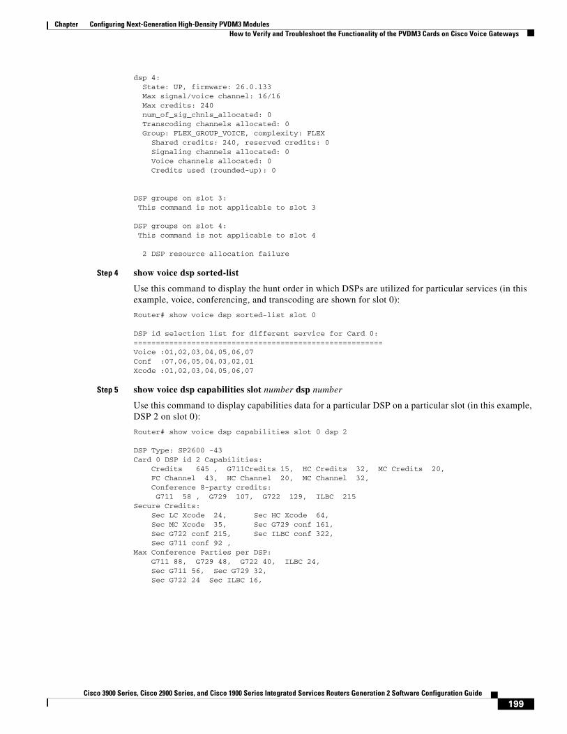
dsp 4: State: UP, firmware: 26.0.133 Max signal/voice channel: 16/16 Max credits: 240 num_of_sig_chnls_allocated: 0 Transcoding channels allocated: 0 Group: FLEX_GROUP_VOICE, complexity: FLEX Shared credits: 240, reserved credits: 0 Signaling channels allocated: 0 Voice channels allocated: 0 Credits used (rounded-up): 0
DSP groups on slot 3: This command is not applicable to slot 3
DSP groups on slot 4: This command is not applicable to slot 4
2 DSP resource allocation failure
Step 4 show voice dsp sorted-list
Use this command to display the hunt order in which DSPs are utilized for particular services (in this example, voice, conferencing, and transcoding are shown for slot 0):
Router# show voice dsp sorted-list slot 0
DSP id selection list for different service for Card 0:========================================================Voice :01,02,03,04,05,06,07Conf :07,06,05,04,03,02,01Xcode :01,02,03,04,05,06,07
Step 5 show voice dsp capabilities slot number dsp number
Use this command to display capabilities data for a particular DSP on a particular slot (in this example, DSP 2 on slot 0):
Router# show voice dsp capabilities slot 0 dsp 2
DSP Type: SP2600 -43 Card 0 DSP id 2 Capabilities: Credits 645 , G711Credits 15, HC Credits 32, MC Credits 20, FC Channel 43, HC Channel 20, MC Channel 32, Conference 8-party credits: G711 58 , G729 107, G722 129, ILBC 215Secure Credits: Sec LC Xcode 24, Sec HC Xcode 64, Sec MC Xcode 35, Sec G729 conf 161, Sec G722 conf 215, Sec ILBC conf 322, Sec G711 conf 92 ,Max Conference Parties per DSP: G711 88, G729 48, G722 40, ILBC 24, Sec G711 56, Sec G729 32, Sec G722 24 Sec ILBC 16,
199Cisco 3900 Series, Cisco 2900 Series, and Cisco 1900 Series Integrated Services Routers Generation 2 Software Configuration Guide

Chapter Configuring Next-Generation High-Density PVDM3 ModulesHow to Verify and Troubleshoot the Functionality of the PVDM3 Cards on Cisco Voice Gateways
Voice Channels: g711perdsp = 43, g726perdsp = 32, g729perdsp = 20, g729aperdsp = 32, g723perdsp = 20, g728perdsp = 20, g723perdsp = 20, gsmperdsp = 32, gsmefrperdsp = 20, gsmamrnbperdsp = 20, ilbcperdsp = 20, modemrelayperdsp = 20 g72264Perdsp = 32, h324perdsp = 20, m_f_thruperdsp = 43, faxrelayperdsp = 32, maxchperdsp = 43, minchperdsp = 20, srtp_maxchperdsp = 27, srtp_minchperdsp = 14, faxrelay_srtp_perdsp = 14, g711_srtp_perdsp = 27, g729_srtp_perdsp = 14, g729a_srtp_perdsp = 24,
Step 6 show voice dsp group slot number
Use this command to display the current status or selective statistics of DSP voice channels for a specific DSP group. For example:
Router# show voice dsp group slot 0dsp 1: State: UP, firmware: 8.4.0 Max signal/voice channel: 16/16 Max credits: 240 Group: FLEX_GROUP_VOICE, complexity: FLEX Shared credits: 240, reserved credits: 0 Signaling channels allocated: 0 Voice channels allocated: 0 Credits used: 0 Oversubscription: can either be an indicator or a counter DSP type: SP260x
Step 7 show voice dsp statistics device
Use this command to display DSP voice statistics for the device:
Router# show voice dsp statistics device
DEVICE DSP CURR AI/RST/WDT ACK MAC TX/RX PACK KEEPALIVEID ID STATE COUNT FAIL ADDRESS COUNT TX/RX/SKP======= === ===== ========= ===== ============= ================= =============0/0/0 1 1 0/0/0 0 00fa.ce25.0000 51645919/37972871 29875/29875/00/0/0 2 1 0/0/0 0 00fa.ce25.0000 51645919/37972871 29875/29875/00/0/0 3 1 0/0/0 0 00fa.ce25.0000 51645919/37972871 29875/29875/00/0/1 4 1 0/0/0 0 00fa.ce25.0001 28355309/20859980 29875/29875/00/0/1 5 1 0/0/0 0 00fa.ce25.0001 28355309/20859980 29875/29875/00/0/1 6 1 0/0/0 0 00fa.ce25.0001 28355309/20859980 29875/29875/0
Step 8 show voice dsp statistics tx-rx
Use this command to display transmitted and received packet counts for the device:
Router# show voice dsp statistics tx-rx
Device and Port Statistics: PVDM-0------------------------------------8903 input packets at port, 15374 output packets at portDevice 0: 6853 packets from device, 11793 packets to device 0 Ctrl & 0 Media out of sequence packets, 0 packets drop0 input error packets, 0 output error packets 0 resource errors packets, 0 gaints vlan id: 2
200Cisco 3900 Series, Cisco 2900 Series, and Cisco 1900 Series Integrated Services Routers Generation 2 Software Configuration Guide

Chapter Configuring Next-Generation High-Density PVDM3 ModulesConfiguration Examples for Configuring the PVDM3 Module on Cisco Voice Gateway Routers
Device 1: 2048 packets from device, 3579 packets to device 0 Ctrl & 0 Media out of sequence packets, 0 packets drop0 input error packets, 0 output error packets 0 resource errors packets, 0 gaints vlan id: 2
Device and Port Statistics: PVDM-1------------------------------------29083 input packets at port, 32627 output packets at portDevice 2: 29081 packets from device, 32627 packets to device 0 Ctrl & 0 Media out of sequence packets, 0 packets drop0 input error packets, 0 output error packets 0 resource errors packets, 0 gaints vlan id: 2
BP throttle change count 0, Current throttle flag 0TX messages at congestion count 0
Step 9 show voice dsp statistics ack
Use this command to display ACK statistics for the device:
Router# show voice dsp statistics ack
DSP ACK RETRY TOTAL WAITING ID DEPTH COUNT RETRANSMITTION FOR ACK=== ===== ====== ============== ========ACK is enabled
Step 10 debug voice dsp crash-dump
Use this command to display debugging information for the crash dump feature (for detailed information about this, see the section Voice DSP Crash Dump File Analysis in Cisco IOS Voice Troubleshooting and Monitoring Guide):
Router# debug voice dsp crash-dump keepalives
Configuration Examples for Configuring the PVDM3 Module on Cisco Voice Gateway Routers
This section provides an example of a running configuration. This example is for reference purposes only and contains IP addresses and telephone numbers that are not actual, valid addresses and telephone numbers; they are provided for illustrative purposes only.
201Cisco 3900 Series, Cisco 2900 Series, and Cisco 1900 Series Integrated Services Routers Generation 2 Software Configuration Guide

Chapter Configuring Next-Generation High-Density PVDM3 ModulesConfiguration Examples for Configuring the PVDM3 Module on Cisco Voice Gateway Routers
show running-config: ExampleRouter# show running-configBuilding configuration...
! voice-card 0:! Mixed PVDM3 and PVDM2 C5510 DSP cards detected.! Mixed DSP types in this slot is an unsupported configuration.! PVDM2 C5510 DSP cards have been disabled.
Current configuration : 3726 bytes!version 12.4no service padservice timestamps debug datetime msecservice timestamps log datetime msecno service password-encryption!hostname Router!boot-start-markerboot-end-marker!card type t1 0 0card type t1 2 0card type t1 2 1logging message-counter sysloglogging buffered 10000000!no aaa new-modelclock timezone PST 8no network-clock-participate slot 2 network-clock-participate wic 0 network-clock-select 1 T1 0/0/1!no ipv6 cefip source-routeip cef!!!!ip host hostname 223.255.254.254 255.255.255.255ntp update-calendarntp server 10.1.32.153ntp peer 10.1.32.153multilink bundle-name authenticated!!!!isdn switch-type primary-ni!!!voice-card 0 dsp services dspfarm!voice-card 2!!!
202Cisco 3900 Series, Cisco 2900 Series, and Cisco 1900 Series Integrated Services Routers Generation 2 Software Configuration Guide

Chapter Configuring Next-Generation High-Density PVDM3 ModulesConfiguration Examples for Configuring the PVDM3 Module on Cisco Voice Gateway Routers
voice service voip allow-connections h323 to h323 allow-connections h323 to sip allow-connections sip to h323 allow-connections sip to sip fax protocol cisco !!!archive log config hidekeys!!controller T1 0/0/0 cablelength long 0db ds0-group 1 timeslots 1-24 type e&m-immediate-start!controller T1 0/0/1 cablelength long 0db pri-group timeslots 1-24!controller T1 2/0!controller T1 2/1!controller T1 2/0/0 cablelength long 0db!controller T1 2/0/1 cablelength long 0db!!!!interface GigabitEthernet0/0 mtu 9600 ip address 10.1.32.147 255.255.0.0 duplex auto speed auto no cdp enable!interface GigabitEthernet0/1 mtu 9600 ip address 10.1.1.1 255.255.255.0 duplex auto speed auto media-type rj45 no cdp enable!interface GigabitEthernet0/2 no ip address shutdown duplex auto speed auto no cdp enable!interface Serial0/0/1:23 no ip address encapsulation hdlc isdn switch-type primary-ni isdn incoming-voice voice no cdp enable!
203Cisco 3900 Series, Cisco 2900 Series, and Cisco 1900 Series Integrated Services Routers Generation 2 Software Configuration Guide

Chapter Configuring Next-Generation High-Density PVDM3 ModulesConfiguration Examples for Configuring the PVDM3 Module on Cisco Voice Gateway Routers
ip forward-protocol ndip route 223.255.254.254 255.255.255.255 10.1.0.1!no ip http serverno ip http secure-server!!!nls resp-timeout 1cpd cr-id 1!!control-plane!!!voice-port 0/0/0:1!voice-port 0/0/1:23!!mgcp fax t38 ecm!sccp local GigabitEthernet0/0sccp ccm 10.1.32.147 identifier 1 priority 1 version 5.0.1 sccp!sccp ccm group 1 associate ccm 1 priority 1 associate profile 3 register CONFERENCE associate profile 2 register UNIVERSAL associate profile 1 register G711_ANY!dspfarm profile 1 transcode codec g711ulaw codec g711alaw codec g722-64 maximum sessions 40 associate application SCCP!dspfarm profile 2 transcode universal codec g723r63 codec ilbc codec g729r8 codec g729br8 codec g723r53 maximum sessions 10 associate application SCCP!dspfarm profile 3 conference codec g711ulaw codec g711alaw codec g729ar8 codec g729abr8 codec g729r8 codec g729br8 maximum conference-participants 32 maximum sessions 2 associate application SCCP shutdown!!
204Cisco 3900 Series, Cisco 2900 Series, and Cisco 1900 Series Integrated Services Routers Generation 2 Software Configuration Guide

Chapter Configuring Next-Generation High-Density PVDM3 ModulesConfiguration Examples for Configuring the PVDM3 Module on Cisco Voice Gateway Routers
dial-peer voice 201 voip session protocol sipv2 incoming called-number 408555.... codec g711ulaw no vad!dial-peer voice 202 voip destination-pattern 408555[0-4]... session protocol sipv2 session target ipv4:10.1.32.153 codec g722-64 no vad!dial-peer voice 203 voip destination-pattern 408555[5-9]... session protocol sipv2 session target ipv4:10.1.32.153 codec g723r53!!!!gatekeeper shutdown!!telephony-service sdspfarm units 5 sdspfarm transcode sessions 128 sdspfarm tag 1 G711_ANY sdspfarm tag 2 UNIVERAL sdspfarm tag 4 CONFERENCE max-ephones 40 max-dn 80 ip source-address 10.1.32.147 port 2000 max-conferences 32 gain -6 transfer-system full-consult create cnf-files version-stamp Jan 01 2002 00:00:00!alias exec dsp show voice dsp group slot 0!line con 0 exec-timeout 0 0line aux 0line vty 0 4 login!exception data-corruption buffer truncatescheduler allocate 20000 1000no process cpu autoprofile hogend
205Cisco 3900 Series, Cisco 2900 Series, and Cisco 1900 Series Integrated Services Routers Generation 2 Software Configuration Guide

Chapter Configuring Next-Generation High-Density PVDM3 ModulesAdditional References
Additional ReferencesThe following sections provide references related to the PVDM3 on Cisco Gateway Routers feature.
Related Documents
Standards
MIBs
RFCs
Related Topic Document Title
Comprehensive command reference information for Cisco IOS voice commands.
Cisco IOS Voice Command Reference
Configuration information for Cisco Voice Gateway Routers that are configured for Cisco Unified Communications Manager.
Cisco Unified Communications Manager and Cisco IOS Interoperability Guide
Complete hardware installation instructions for installing the PVDM3.
Cisco 2900 Series and 3900 Series Integrated Services Routers Hardware Installation Guide
Standard Title
None —
MIB MIBs Link
CISCO-DSP-MGMT-MIB To locate and download MIBs for selected platforms, Cisco IOS releases, and feature sets, use Cisco MIB Locator found at:
http://www.cisco.com/go/mibs
RFC Title
None —
206Cisco 3900 Series, Cisco 2900 Series, and Cisco 1900 Series Integrated Services Routers Generation 2 Software Configuration Guide

Chapter Configuring Next-Generation High-Density PVDM3 ModulesFeature Information for Configuring the PVDM3 Module on Cisco Voice Gateway Routers
Technical Assistance
Feature Information for Configuring the PVDM3 Module on Cisco Voice Gateway Routers
Table 3 lists the release history for this feature.
Not all commands may be available in your Cisco IOS software release. For release information about a specific command, see the command reference documentation.
Use Cisco Feature Navigator to find information about platform support and software image support. Cisco Feature Navigator enables you to determine which Cisco IOS and Catalyst OS software images support a specific software release, feature set, or platform. To access Cisco Feature Navigator, go to http://www.cisco.com/go/cfn. An account at Cisco.com is not required.
Note Table 3 lists only the Cisco IOS software release that introduced support for a given feature in a given Cisco IOS software release train. Unless noted otherwise, subsequent releases of that Cisco IOS software release train also support that feature.
Description Link
The Cisco Support and Documentation website provides online resources to download documentation, software, and tools. Use these resources to install and configure the software and to troubleshoot and resolve technical issues with Cisco products and technologies. Access to most tools on the Cisco Support and Documentation website requires a Cisco.com user ID and password.
http://www.cisco.com/cisco/web/support/index.html
Table 3 Feature Information for Configuring the PVDM3 Module on Cisco Voice Gateway Routers
Feature Name Releases Feature Information
Configuring the PVDM3 Module on Cisco Voice Gateway Routers
15.0(1)M15.1(1)T15.1(4)M
The PVDM3 DSP1 modules support high-density audio applications on the Cisco voice gateways. These DSP modules provide resources for voice termination, voice compression algorithms, echo cancellation, conferencing and transcoding, and support for modems and fax calls.
In Release 15.0(1)M, this feature is supported only on the Cisco 2901, Cisco 2911, Cisco 2921, Cisco 2951, Cisco 3925, and Cisco 3945.
In Release 15.1(1)T, this feature is supported only on the Cisco 3925E and Cisco 3945E ISRs.
1. DSP = digital signal processor
207Cisco 3900 Series, Cisco 2900 Series, and Cisco 1900 Series Integrated Services Routers Generation 2 Software Configuration Guide

Chapter Configuring Next-Generation High-Density PVDM3 ModulesGlossary
GlossaryAGC—Automatic Gain Control.
BCN—Backward Congestion Notification.
CM—Connection manager (TDM).
COS—Class of service, 802.1p.
DA—Ethernet Destination Address.
DMA—Direct Memory Access.
DSA—Distributed Switch Architecture.
DSP—Digital Signal Processor.
DSPRM—DSP Resource Manager.
DTMF—Dual-tone multi-frequency.
ECAN—Echo Canceller.
EVSM—Extended Voice Service Module.
FC—Flex Complexity.
FPGA—Field-Programmable Gate Array.
HC—High Complexity.
HDLC—High-level Data Link Control Protocol.
HPI—Host Port Interface.
LC—Low Complexity.
MAC—Media Access Control.
MC—Medium Complexity.
McBSP—Multi-Channel Buffer Serial Port.
MTBF—Mean Time Between Failures.
MTP—Media Termination Point.
NTE—Named Telephone Events.
OIR—Online Insertion and Removal.
PCE—Packet Classification Engine.
PVDM3—Next generation Packet Voice Data Module.
PVDM2—PVDM hosting 5510 DSP.
QOS—Quality of Service.
REA—Ethernet Ready Announcement, like bootp message.
RI—Restart indication from DSP/Device.
RTP—Real-time Transport Protocol.
SA—Ethernet source address.
SGMII—Serial Gigabit Media Independent Interface.
SM—Service Module.
SRTP—Secure Real-time Transport Protocol.
208Cisco 3900 Series, Cisco 2900 Series, and Cisco 1900 Series Integrated Services Routers Generation 2 Software Configuration Guide

Chapter Configuring Next-Generation High-Density PVDM3 ModulesGlossary
TDM—Time Division Multiplexing.
UHPI—Universal Host Port Interface.
VIC—Voice Interface Card.
VLAN—Virtual LAN.
VNM—Voice Network Module.
VWIC—Voice/WAN Interface Card.
209Cisco 3900 Series, Cisco 2900 Series, and Cisco 1900 Series Integrated Services Routers Generation 2 Software Configuration Guide

Chapter Configuring Next-Generation High-Density PVDM3 ModulesGlossary
210Cisco 3900 Series, Cisco 2900 Series, and Cisco 1900 Series Integrated Services Routers Generation 2 Software Configuration Guide