cisco 850 series and cisco 870 series access routers ... · cisco 857: 1antenna cisco 877: 2...
TRANSCRIPT

Cisco 850 Series and Cisco 870 Series Access Route78-16262-04
English
C H A P T E R 1
Cisco 850 Series and Cisco 870 Series Access Routers Cabling and Setup Quick Start GuideContents• Cisco One-Year Limited Hardware Warranty Terms, page 1-2
• Locate the Product Serial Number, page 1-3
• Before Installation, page 1-3
• Connect the Antenna to the Wireless Router (Optional), page 1-7
• Connect the Power-over-Ethernet Module to the Cisco 870 Series Router (Optional), page 1-9
• Typical Installations of the Cisco 850 Series and Cisco 870 Series Routers, page 1-11
• Connect the Router, page 1-16
• Install SDM and Configure the Router, page 1-18
• Related Documentation, page 1-19
• Obtaining Documentation and Submitting a Service Request, page 1-20
1-1rs Cabling and Setup Quick Start Guide
Chapter 1 Cisco 850 Series and Cisco 870 Series Access Routers Cabling and Setup Quick Start GuideCisco One-Year Limited Hardware Warranty Terms
Cisco One-Year Limited Hardware Warranty TermsThe following are special terms applicable to your hardware warranty. Your formal Warranty Statement, including the warranty applicable to Cisco software, appears in the Cisco Information Packet that accompanies your Cisco product.
Duration of Hardware Warranty: One (1) Year
Replacement, Repair or Refund Procedure for Hardware: Cisco or its service center will use commercially reasonable efforts to ship a replacement part within ten (10) working days after receipt of the RMA request. Actual delivery times may vary depending on Customer location.
Cisco reserves the right to refund the purchase price as its exclusive warranty remedy.
To Receive a Return Materials Authorization (RMA) Number: Please contact the party from whom you purchased the product. If you purchased the product directly from Cisco, contact your Cisco Sales and Service Representative.
Complete the form below and keep for ready reference.
Product warranty terms and other information applicable to Cisco products are available at the following URL:
http://www.cisco.com/go/warranty
Product purchased from:
Their telephone number:
Product Model and Serial number:
Maintenance Contract number:
1-2Cisco 850 Series and Cisco 870 Series Access Routers Cabling and Setup Quick Start Guide
78-16262-04
Chapter 1 Cisco 850 Series and Cisco 870 Series Access Routers Cabling and Setup Quick Start GuideLocate the Product Serial Number
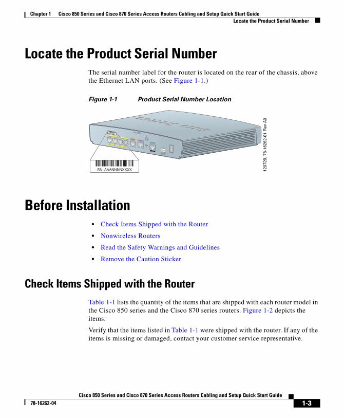
Locate the Product Serial NumberThe serial number label for the router is located on the rear of the chassis, above the Ethernet LAN ports. (See Figure 1-1.)
Figure 1-1 Product Serial Number Location
Before Installation• Check Items Shipped with the Router
• Nonwireless Routers
• Read the Safety Warnings and Guidelines
• Remove the Caution Sticker
Check Items Shipped with the RouterTable 1-1 lists the quantity of the items that are shipped with each router model in the Cisco 850 series and the Cisco 870 series routers. Figure 1-2 depicts the items.
Verify that the items listed in Table 1-1 were shipped with the router. If any of the items is missing or damaged, contact your customer service representative.
1207
29, 7
8-16
262-
01 R
ev A
0
G.SHDSL
ISDN S/T
LAN
FE0FE1
FE2FE3
Cisco 878
CONSOLE
AUX
RESET
+5,+9 VDC
SN: AAANNNNXXXX
SN: AAANNNNXXXX
1-3Cisco 850 Series and Cisco 870 Series Access Routers Cabling and Setup Quick Start Guide
78-16262-04

Chapter 1 Cisco 850 Series and Cisco 870 Series Access Routers Cabling and Setup Quick Start GuideBefore Installation
Table 1-1 Items Shipped with Cisco 850 Series and Cisco 870 Series Routers
ItemCisco 851 and Cisco 871
Cisco 857 and Cisco 877 Cisco 876 Cisco 878
Ethernet cable (straight-through) 1 1 1 1
DSL1 cable
1. DSL = digital subscriber line. Used for an asynchronous digital subscriber line (ADSL) or multirate symmetrical high-data-rate digital subscriber line (G.SHDSL).
Not applicable 12
2. An RJ-11-to-RJ-11 straight-through cable is shipped, unless an RJ-11-to-RJ-11 crossover cable is specified.
13
3. An RJ-11-to-RJ-11 straight-through cable is shipped, unless an RJ-11-to-RJ-11 crossover cable or an RJ-11-to-RJ-45 cable is specified.
13
ISDN4 S/T cable
4. ISDN = Integrated Services Digital Network.
Not applicable Not applicable Optional Optional
Console cable 1 1 1 1
Console-auxiliary5 cable
5. Console-auxiliary cable is used to connect the router console port to an asynchronous modem for dial backup or remote management.
Optional Optional Optional Optional
Power adapter 1 1 1 1
Power cord6
6. Power cords are ordered as applicable to country or geographic region.
1 1 1 1
Cisco documentation7
7. Includes the Regulatory Compliance and Safety Information for Cisco 800 Series Routers document and the Cisco 850 Series and Cisco 870 Series Access Routers Cabling and Setup Quick Start Guide (this document). Also includes the Declarations of Conformity and Regulatory Information for Cisco Access Products with 802.11a/b/g and 802.11b/g Radios document for wireless models.
1 1 1 1
Cisco Router and Security Device Manager (SDM) software CD
1 1 1 1
Swivel-mount dipole antenna (wireless router models only)
Cisco 851: 1 antenna
Cisco 871: 2 antennas
Cisco 857: 1 antenna
Cisco 877: 2 antennas
2 2
1-4Cisco 850 Series and Cisco 870 Series Access Routers Cabling and Setup Quick Start Guide
78-16262-04
Chapter 1 Cisco 850 Series and Cisco 870 Series Access Routers Cabling and Setup Quick Start GuideBefore Installation
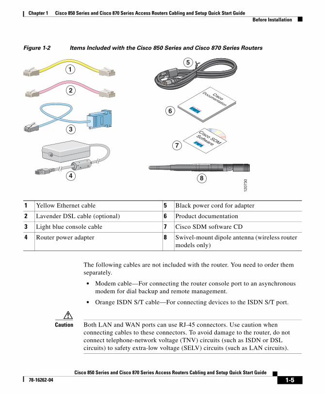
Figure 1-2 Items Included with the Cisco 850 Series and Cisco 870 Series Routers
The following cables are not included with the router. You need to order them separately.
• Modem cable—For connecting the router console port to an asynchronous modem for dial backup and remote management.
• Orange ISDN S/T cable—For connecting devices to the ISDN S/T port.
Caution Both LAN and WAN ports can use RJ-45 connectors. Use caution when connecting cables to these connectors. To avoid damage to the router, do not connect telephone-network voltage (TNV) circuits (such as ISDN or DSL circuits) to safety extra-low voltage (SELV) circuits (such as LAN circuits).
1 Yellow Ethernet cable 5 Black power cord for adapter
2 Lavender DSL cable (optional) 6 Product documentation
3 Light blue console cable 7 Cisco SDM software CD
4 Router power adapter 8 Swivel-mount dipole antenna (wireless router models only)
6
7
1207
30
5
2
3
4 8
1-5Cisco 850 Series and Cisco 870 Series Access Routers Cabling and Setup Quick Start Guide
78-16262-04
Chapter 1 Cisco 850 Series and Cisco 870 Series Access Routers Cabling and Setup Quick Start GuideBefore Installation
Nonwireless RoutersPortions of this guide do not apply to nonwireless models of the Cisco 850 series and Cisco 870 series routers. Some illustrations show the router with antennas attached, whereas the nonwireless routers do not have antennas or antenna connectors on the back panel. However, except for the “Connect the Antenna to the Wireless Router (Optional)” section, the connection procedures are the same for wireless and nonwireless router models.
Read the Safety Warnings and GuidelinesBefore you begin to connect your router, read the Regulatory Compliance and Safety Information for Cisco 800 Series Routers document that is shipped with the router. This document provides important safety warnings and guidelines.
Remove the Caution StickerLocate the yellow caution label that covers the LAN ports. Simply peel off the label and the LAN ports are ready for use. Be sure that you do not connect ISDN telephone lines to these LAN ports.
1-6Cisco 850 Series and Cisco 870 Series Access Routers Cabling and Setup Quick Start Guide
78-16262-04
Chapter 1 Cisco 850 Series and Cisco 870 Series Access Routers Cabling and Setup Quick Start GuideConnect the Antenna to the Wireless Router (Optional)
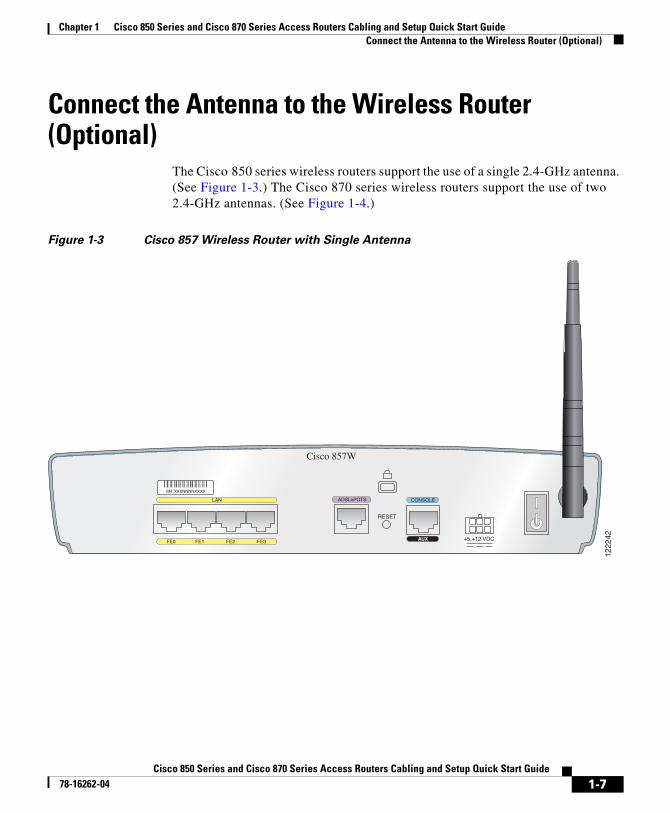
Connect the Antenna to the Wireless Router (Optional)
The Cisco 850 series wireless routers support the use of a single 2.4-GHz antenna. (See Figure 1-3.) The Cisco 870 series wireless routers support the use of two 2.4-GHz antennas. (See Figure 1-4.)
Figure 1-3 Cisco 857 Wireless Router with Single Antenna
ADSLoPOTSLAN
FE0 FE1 FE2 FE3
Cisco 857W
CONSOLE
AUX
RESET
+5,+12 VDC
1222
42
SN: XXXNNNNXXXX
1-7Cisco 850 Series and Cisco 870 Series Access Routers Cabling and Setup Quick Start Guide
78-16262-04

Chapter 1 Cisco 850 Series and Cisco 870 Series Access Routers Cabling and Setup Quick Start GuideConnect the Antenna to the Wireless Router (Optional)
Figure 1-4 Cisco 871 Wireless Router with Two Antennas
To connect the antenna or antennas to a wireless router, follow these steps:
Step 1 Attach each antenna to a reverse-polarity threaded Neill-Concelman (RP-TNC) connector on the back of the router and tighten the connector hand-tight.
Step 2 After you connect the antenna to the back of the router, orient the antenna so that it is straight up.
LAN
FE0 FE1 FE2 FE3
Cisco 871W
CONSOLE
AUX
RESET
+5,+12 VDC
LEFT RIGHT / PRIMARY
1
0
WAN
FE4
1222
41
SN: XXXNNNNXXXX
1-8Cisco 850 Series and Cisco 870 Series Access Routers Cabling and Setup Quick Start Guide
78-16262-04
Chapter 1 Cisco 850 Series and Cisco 870 Series Access Routers Cabling and Setup Quick Start GuideConnect the Power-over-Ethernet Module to the Cisco 870 Series Router (Optional)
Connect the Power-over-Ethernet Module to the Cisco 870 Series Router (Optional)
Power-over-Ethernet (PoE) is supported on the Cisco 870 Series routers only. If you purchased a PoE module, connect all four Ethernet cables on the PoE module to the four LAN Ethernet ports on the Cisco 870 Series router. (See Figure 1-5.) Make sure that you connect all four Ethernet cables.
If the cables are too close together for easy insertion, move the plastic cable guard away from the connector end of the cables.
Caution To ensure proper PoE module operation, do not connect the PoE module power supply to the PoE module before you connect the PoE module to the router.
Although Figure 1-5 shows the Cisco 871 router connected to a PoE module, this connection works for all router models in the Cisco 870 series.
Note When you connect a device (such as a PC or IP phone) to the PoE module, you may notice a 1- to 2-second delay before the LED indicator for the port comes on.
1-9Cisco 850 Series and Cisco 870 Series Access Routers Cabling and Setup Quick Start Guide
78-16262-04

Chapter 1 Cisco 850 Series and Cisco 870 Series Access Routers Cabling and Setup Quick Start GuideConnect the Power-over-Ethernet Module to the Cisco 870 Series Router (Optional)
Figure 1-5 Connecting the PoE Module to the Router
1 Cisco 870 series router 5 Router power adapter
2 Ethernet cables on the PoE module (four RJ-45 connectors in series)
6 PoE power plug
3 PoE module 7 Router power plug
4 PoE power adapter
1223
51
+5,+12 VDC
LEFT RIGHT / PRIMARY
LAN
FE0 FE1 FE2 FE3
Cisco 871W
CONSOLE
AUX
RESET
1
0
WAN
FE4
1
2
4
6
To LAN3210
PWR
3
5
7
SN: XXXNNNNXXXX
1-10Cisco 850 Series and Cisco 870 Series Access Routers Cabling and Setup Quick Start Guide
78-16262-04
Chapter 1 Cisco 850 Series and Cisco 870 Series Access Routers Cabling and Setup Quick Start GuideTypical Installations of the Cisco 850 Series and Cisco 870 Series Routers
Typical Installations of the Cisco 850 Series and Cisco 870 Series Routers
Typical installations of the Cisco 850 series and Cisco 870 series routers are depicted in Figure 1-6 through Figure 1-9, as follows:
• Cisco 851 and Cisco 871 router—See Figure 1-6.
• Cisco 857 and Cisco 87 router—See Figure 1-7.
• Cisco 876 router—See Figure 1-8.
• Cisco 878 router—See Figure 1-9.
Figure 1-6 shows a typical installation of a Cisco 851 or Cisco 871 router. This figure shows the back panel of a Cisco 871 router, which has two Universal Serial Bus (USB) ports. The Cisco 851 router does not have any USB ports; however, the connections on the other ports are the same for both the Cisco 851 and the Cisco 871 routers.
1-11Cisco 850 Series and Cisco 870 Series Access Routers Cabling and Setup Quick Start Guide
78-16262-04

Chapter 1 Cisco 850 Series and Cisco 870 Series Access Routers Cabling and Setup Quick Start GuideTypical Installations of the Cisco 850 Series and Cisco 870 Series Routers
Figure 1-6 Typical Installation of a Cisco 851 or Cisco 871 Router
1 Ethernet connection to an external switch 4 Console port
2 Ethernet connection to a PC 5 Power adapter
3 WAN connection using a broadband modem to the Internet
LAN
4 3 2 1
Cisco 871W
CONSOLE
AUX
RESET
+5,+12 VDC
LEFT RIGHT / PRIMARY
1
0
WAN
FE4FE0 FE1 FE2 FE3
1X
2X
1X
2X
1
InternetInternet
1 2 53 4
1222
37
SN: XXXNNNNXXXX
1-12Cisco 850 Series and Cisco 870 Series Access Routers Cabling and Setup Quick Start Guide
78-16262-04

Chapter 1 Cisco 850 Series and Cisco 870 Series Access Routers Cabling and Setup Quick Start GuideTypical Installations of the Cisco 850 Series and Cisco 870 Series Routers
Figure 1-7 shows a typical installation of a Cisco 857 or Cisco 877 router.
Figure 1-7 Typical Installation of a Cisco 857 or a Cisco 877 Router
1 Ethernet connection to an external switch 4 Console port
2 Ethernet connection to a PC 5 Power adapter
3 ADSL-over-POTS connection
RIGHT / PRIMARY
ADSLoPOTSETHERNET LAN
3 2 1 0
Cisco 877W
CONSOLE
AUX
RESET
+5,+12 VDC
LEFT
FE4 FE3 FE2 FE1
1X
2X
1X
2X
1
1 2 53
1222
38
4
SN: XXXNNNNXXXX
1-13Cisco 850 Series and Cisco 870 Series Access Routers Cabling and Setup Quick Start Guide
78-16262-04

Chapter 1 Cisco 850 Series and Cisco 870 Series Access Routers Cabling and Setup Quick Start GuideTypical Installations of the Cisco 850 Series and Cisco 870 Series Routers
Figure 1-8 shows a typical installation of a Cisco 876 router.
Figure 1-8 Typical Installation of a Cisco 876 Router
1 Ethernet connection to an external switch 4 ADSL-over-ISDN connection
2 Ethernet connection to a PC 5 Console port
3 ISDN S/T connection 6 Power adapter
ADSL o ISDNISDN S/TLAN
FE0 FE1 FE2 FE3
Cisco 876W
CONSOLE
AUX
RESET
+5,+12 VDC
LEFT RIGHT / PRIMARY
1X
2X
1X
2X
1
1 2 6
1222
39
543
SN: XXXNNNNXXXX
1-14Cisco 850 Series and Cisco 870 Series Access Routers Cabling and Setup Quick Start Guide
78-16262-04
Chapter 1 Cisco 850 Series and Cisco 870 Series Access Routers Cabling and Setup Quick Start GuideTypical Installations of the Cisco 850 Series and Cisco 870 Series Routers
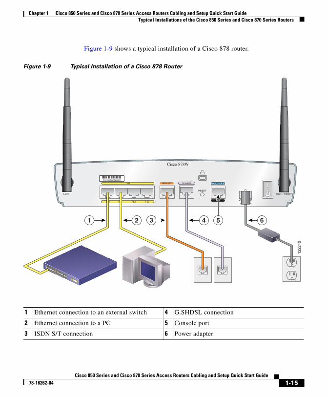
Figure 1-9 shows a typical installation of a Cisco 878 router.
Figure 1-9 Typical Installation of a Cisco 878 Router
1 Ethernet connection to an external switch 4 G.SHDSL connection
2 Ethernet connection to a PC 5 Console port
3 ISDN S/T connection 6 Power adapter
G.SHDSLISDN S/TLAN
FE0 FE1 FE2 FE3
Cisco 878W
CONSOLE
AUX
RESET
+5,+12 VDC
LEFT RIGHT / PRIMARY
1X
2X
1X
2X
1
1 2 643
1222
40
5
SN: XXXNNNNXXXX
1-15Cisco 850 Series and Cisco 870 Series Access Routers Cabling and Setup Quick Start Guide
78-16262-04

Chapter 1 Cisco 850 Series and Cisco 870 Series Access Routers Cabling and Setup Quick Start GuideConnect the Router
Connect the RouterConnect the router, referring to the typical installation for your router model as shown in the “Typical Installations of the Cisco 850 Series and Cisco 870 Series Routers” section on page 1-11.
Follow these steps to connect the router to the power supply, to your local network, and to your service provider:
Step 1 Wireless models only: Make sure that you have attached the antennas to the router as described in the “Connect the Antenna to the Wireless Router (Optional)” section on page 1-7.
Step 2 If you are using a PoE module, make sure that it is connected to the router (see “Connect the Power-over-Ethernet Module to the Cisco 870 Series Router (Optional)” section on page 1-9). Connect the Ethernet devices to the PoE module, not to the router.
Step 3 If you are connecting more than four PCs to the router, connect the router to a switch or hub by using a yellow Ethernet cable, as shown in Figure 1-6 through Figure 1-9.
Step 4 Connect a PC directly to your router, as shown in Figure 1-6 through Figure 1-9. Turn off the PC so that it will obtain an IP address from the router when it is turned on. You can connect additional PCs to the remaining numbered Ethernet ports.
Step 5 The console port is a service port to which you can connect a terminal or PC in order to configure the software by using the command-line interface (CLI) or to troubleshoot problems with the router. If you need access to the router console, connect a PC or terminal to the console port.
Note By connecting the console port to an asynchronous modem using the optional router modem cable, you can add dial backup and remote management capabilities to the router.
Step 6 Cisco 851 and Cisco 871 routers only: Connect the second yellow Ethernet cable between the router Ethernet WAN port and an available port on an installed digital subscriber line (DSL), cable, or long-reach Ethernet modem as shown in Figure 1-6.
1-16Cisco 850 Series and Cisco 870 Series Access Routers Cabling and Setup Quick Start Guide
78-16262-04
Chapter 1 Cisco 850 Series and Cisco 870 Series Access Routers Cabling and Setup Quick Start GuideConnect the Router
Follow the instructions provided with your broadband modem to determine which port on the modem to connect to. Turn on the broadband modem if it is not already turned on.
Step 7 Cisco 871 router only: Connect supported USB devices such as flash memory modules or eTokens to the two USB ports. For more information, see the Cisco Access Router USB Flash Module and USB eToken Hardware Installation Guide. Proceed to Step 12.
Step 8 Cisco 857 and Cisco 877 routers only: Connect the ADSLoPOTS port on the router to the telephone wall jack by using the lavender DSL cable. If the ADSL line is also used for voice communication, you can prevent disruption to data communication by connecting the router to an ADSL splitter, or by installing microfilters between telephones or fax equipment and the wall jack. Proceed to Step 12.
Caution Both LAN and WAN ports can use RJ-45 connectors. Use caution when connecting cables to these connectors. To avoid damage to the router, do not connect telephone-network voltage (TNV) circuits (such as ISDN or DSL circuits) to safety extra-low voltage (SELV) circuits (such as LAN circuits).
Step 9 Cisco 876 and Cisco 878 routers only: For dial backup and remote management, you can connect the ISDN S/T port to a Network Termination (NT1) box or an ADSL splitter, using the orange ISDN S/T cable (ordered separately). Continue to Step 10 or proceed to Step 11, as appropriate for your router model.
Step 10 Cisco 876 routers only: Connect the DSL cable to the ADSLoISDN port on the router and to the ADSL splitter or wall socket. If you are using an ADSL splitter, connect the splitter to the wall socket using a Category 5 unshielded twisted-pair cable. Proceed to Step 12.
Step 11 Cisco 878 routers only: Connect the DSL cable to the G.SHDSL port on the router and to the wall socket.
Step 12 All router models: Connect power to the router, and turn on the router. Be sure to use the power supply that was shipped with the router. Other power supplies will not connect to the router.
The green OK LED on the front panel of the router lights up when you connect the router to a power source. The router is now ready for use.
If the green OK LED does not turn on, see the “Troubleshooting” chapter in the Cisco 850 Series and Cisco 870 Series Routers Hardware Installation Guide.
1-17Cisco 850 Series and Cisco 870 Series Access Routers Cabling and Setup Quick Start Guide
78-16262-04

Chapter 1 Cisco 850 Series and Cisco 870 Series Access Routers Cabling and Setup Quick Start GuideInstall SDM and Configure the Router
Note For Cisco 857, Cisco 876, Cisco 877, and Cisco 878 routers, the DSL line must have been provisioned by your service provider and must be correctly configured. Check the carrier detect (CD) status on the ADSL CD LED or G.SHDSL CD LED on the router. If the ADSL CD LED or G.SHDSL CD LED does not light up, check with your service provider.
Step 13 If you have connected a PoE module to the router, connect the PoE module power supply to the input jack on the back panel of the PoE module. The green LED on the PoE front panel lights up and power is provided to devices connected to the PoE.
See the Cisco 870 Series Routers Hardware Installation Guide for detailed connection instructions.
Install SDM and Configure the RouterTo install Cisco SDM for configuring the router, follow these steps:
Step 1 Connect a PC to any router LAN port, as shown in Figure 1-7, Figure 1-8 and Figure 1-9.
Step 2 Insert the Cisco SDM software CD into the CD drive of the PC. An installation wizard is launched from the CD. Install Cisco SDM by following the instructions on the installation wizard user interface.
Step 3 Use Cisco SDM to configure the router by following the instructions in the Cisco Router and Security Device Manager (SDM) Quick Start Guide.
1-18Cisco 850 Series and Cisco 870 Series Access Routers Cabling and Setup Quick Start Guide
78-16262-04

Chapter 1 Cisco 850 Series and Cisco 870 Series Access Routers Cabling and Setup Quick Start GuideRelated Documentation
Related DocumentationThis document describes the basic process of cabling and setting up the Cisco 850 series and Cisco 870 series routers. See the following documents for more information:
• Cisco 850 Series and Cisco 870 Series Access Routers Hardware Installation Guide—Provides detailed cabling and hardware information for the Cisco 850 series and Cisco 870 series routers.
• Cisco Router and Security Device Manager (SDM) Quick Start Guide—Provides step-by-step instructions for configuring the router and wireless features by using the Cisco SDM web-based GUI.
• Cisco 850 Series and Cisco 870 Series Access Routers Software Configuration Guide—Provides software configuration information and examples for the Cisco 850 and Cisco 870 series routers.
• Cisco Access Router Wireless Configuration Guide—Provides wireless software configuration information for Cisco access routers, including the Cisco 850 series and Cisco 870 series.
• Upgrading Memory in Cisco 800 Series Routers—Provides information about upgrading memory in the Cisco 800 series routers.
• Regulatory Compliance and Safety Information for Cisco 800 Series and SOHO Series Routers—Provides regulatory compliance and safety information about Cisco 800 series and SOHO series routers.
• Cisco Access Router USB Flash Module and USB eToken Hardware Installation Guide—Provides information about installing USB flash memory modules and eTokens.
These documents are available on the World Wide Web. You can access the most current Cisco documentation on the World Wide Web at the following sites:
• http://www.cisco.com
• http://www-china.cisco.com
• http://www-europe.cisco.com
1-19Cisco 850 Series and Cisco 870 Series Access Routers Cabling and Setup Quick Start Guide
78-16262-04
Chapter 1 Cisco 850 Series and Cisco 870 Series Access Routers Cabling and Setup Quick Start GuideObtaining Documentation and Submitting a Service Request
Obtaining Documentation and Submitting a Service Request
For information on obtaining documentation, submitting a service request, and gathering additional information, see the monthly What’s New in Cisco Product Documentation, which also lists all new and revised Cisco technical documentation, at:
http://www.cisco.com/en/US/docs/general/whatsnew/whatsnew.html
Subscribe to the What’s New in Cisco Product Documentation as a Really Simple Syndication (RSS) feed and set content to be delivered directly to your desktop using a reader application. The RSS feeds are a free service and Cisco currently supports RSS Version 2.0.
1-20Cisco 850 Series and Cisco 870 Series Access Routers Cabling and Setup Quick Start Guide
78-16262-04