cisco 850 series and cisco 870 series
TRANSCRIPT

8/11/2019 Cisco 850 Series and Cisco 870 Series
http://slidepdf.com/reader/full/cisco-850-series-and-cisco-870-series 1/196
Corporate Headquarters
Cisco Systems, Inc.170 West Tasman DriveSan Jose, CA 95134-1706USAhttp://www.cisco.comTel: 408 526-4000
800 553-NETS (6387)Fax: 408 526-4100
Cisco 850 Series and Cisco 870 SeriesAccess Routers SoftwareConfiguration Guide
Text Part Number: OL-5332-01

8/11/2019 Cisco 850 Series and Cisco 870 Series
http://slidepdf.com/reader/full/cisco-850-series-and-cisco-870-series 2/196
THE SPECIFICATIONS AND INFORMATION REGARDING THE PRODUCTS IN THIS MANUAL ARE SUBJECT TO CHANGE WITHOUT NOTICE. ALLSTATEMENTS, INFORMATION, AND RECOMMENDATIONS IN THIS MANUAL ARE BELIEVED TO BE ACCURATE BUT ARE PRESENTED WITHOUTWARRANTY OF ANY KIND, EXPRESS OR IMPLIED. USERS MUST TAKE FULL RESPONSIBILITY FOR THEIR APPLICATION OF ANY PRODUCTS.
THE SOFTWARE LICENSE AND LIMITED WARRANTY FOR THE ACCOMPANYING PRODUCT ARE SET FORTH IN THE INFORMATION PACKET THAT
SHIPPED WITH THE PRODUCT AND ARE INCORPORATED HEREIN BY THIS REFERENCE. IF YOU ARE UNABLE TO LOCATE THE SOFTWARE LICENSEOR LIMITED WARRANTY, CONTACT YOUR CISCO REPRESENTATIVE FOR A COPY.
The Cisco implementation of TCP header compression is an adaptation of a program developed by the University of California, Berkeley (UCB) as part of UCB’s publicdomain version of the UNIX operating system. All rights reserved. Copyright © 1981, Regents of the University of California.
NOTWITHSTANDING ANY OTHER WARRANTY HEREIN, ALL DOCUMENT FILES AND SOFTWARE OF THESE SUPPLIERS ARE PROVIDED “AS IS” WITHALL FAULTS. CISCO AND THE ABOVE-NAMED SUPPLIERS DISCLAIM ALL WARRANTIES, EXPRESSED OR IMPLIED, INCLUDING, WITHOUTLIMITATION, THOSE OF MERCHANTABILITY, FITNESS FOR A PARTICULAR PURPOSE AND NONINFRINGEMENT OR ARISING FROM A COURSE OFDEALING, USAGE, OR TRADE PRACTICE.
IN NO EVENT SHALL CISCO OR ITS SUPPLIERS BE LIABLE FOR ANY INDIRECT, SPECIAL, CONSEQUENTIAL, OR INCIDENTAL DAMAGES, INCLUDING,WITHOUT LIMITATION, LOST PROFITS OR LOSS OR DAMAGE TO D ATA ARISING OUT OF THE USE OR INABILITY TO USE THIS MANUAL, EVEN IF CISCOOR ITS SUPPLIERS HAVE BEEN ADVISED OF THE POSSIBILITY OF SUCH DAMAGES.
CCSP, the Cisco Square Bridge logo, Follow Me Browsing, and StackWise are trademarks of Cisco Systems, Inc.; Changing the Way We Work, Live, Play, and Learn, and iQuickStudy are s ervice marks of Cisco Systems, Inc.; and Access Registrar, Aironet, ASIST, BPX, Catalyst, CCDA, CCDP, CCIE, CCIP, CCNA, CCNP, Cisco, the Cisco Certified
Internetwork Expert logo, Cisco IOS, Cisco Press, Cisco Systems, Cisco Systems Capital, the Cisco Systems logo, Cisco Unity, Empowering the Internet Generation,Enterprise/Solver, EtherChannel, EtherFast, EtherSwitch, Fast Step, FormShare, GigaDrive, GigaStack, HomeLink, Internet Quotient, IOS, IP/TV, iQ Expertise, the iQ logo, iQNet Readiness Scorecard, LightStream, Linksys, MeetingPlace, MGX, the Networkers logo, Networking Academy, Network Registrar, Packet , PIX, Post-Routing, Pre-Routing,ProConnect, RateMUX, ScriptShare, SlideCast, SMARTnet, StrataView Plus, SwitchProbe, TeleRouter, The Fastest Way to Increase Your Internet Quotient, TransPath, and VCOare registered trademarks of Cisco Systems, Inc. and/or its affiliates in the United States and certain other countries.
All other trademarks mentioned in this document or Website are the property of their respective owners. The use of the word partner does not imply a partnership relationshipbetween Cisco and any other company. (0501R)
Cisco 850 Series and Cisco 870 Series Access Routers Software Configuration Guide Copyright © 2005, Cisco Systems, Inc. All rights reserved.

8/11/2019 Cisco 850 Series and Cisco 870 Series
http://slidepdf.com/reader/full/cisco-850-series-and-cisco-870-series 3/196
3Cisco 850 Series and Cisco 870 Series Access Routers Software Configuration Guide
OL-5332-01
C O N T E N T S
Preface 11
Audience 11
Organization 12
Conventions 13
Notes, Cautions, and Timesavers 13
Command Conventions 13
Related Documents 14
Obtaining Documentation and Submitting a Service Request 14
P A R T 1 Getting Started
C H A P T E R 1 Basic Router Configuration 1
Interface Port Labels 1
Viewing the Default Configuration 2
Information Needed for Configuration 4
Configuring Basic Parameters 5
Configure Global Parameters 5
Configure Fast Ethernet LAN Interfaces 6Configure WAN Interfaces 6
Configure the Fast Ethernet WAN Interface 6
Configure the ATM WAN Interface 7
Configure the Wireless Interface 7
Configuring a Loopback Interface 8
Configuration Example 8
Verifying Your Configuration 9
Configuring Command-Line Access to the Router 9
Configuration Example 11
Configuring Static Routes 11
Configuration Example 12
Verifying Your Configuration 12
Configuring Dynamic Routes 12
Configuring RIP 13
Configuration Example 14
Verifying Your Configuration 14

8/11/2019 Cisco 850 Series and Cisco 870 Series
http://slidepdf.com/reader/full/cisco-850-series-and-cisco-870-series 4/196

8/11/2019 Cisco 850 Series and Cisco 870 Series
http://slidepdf.com/reader/full/cisco-850-series-and-cisco-870-series 5/196
Contents
5Cisco 850 Series and Cisco 870 Series Access Routers Software Configuration Guide
OL-5332-01
Configure Group Policy Information 5
Apply Mode Configuration to the Crypto Map 6
Enable Policy Lookup 6
Configure IPSec Transforms and Protocols 7Configure the IPSec Crypto Method and Parameters 8
Apply the Crypto Map to the Physical Interface 9
Create an Easy VPN Remote Configuration 10
Verifying Your Easy VPN Configuration 11
Configuration Example 11
C H A P T E R 7 Configuring VPNs Using an IPSec Tunnel and Generic Routing Encapsulation 1
Configure a VPN 2
Configure the IKE Policy 3Configure Group Policy Information 4
Enable Policy Lookup 5
Configure IPSec Transforms and Protocols 5
Configure the IPSec Crypto Method and Parameters 6
Apply the Crypto Map to the Physical Interface 7
Configure a GRE Tunnel 8
Configuration Example 9
C H A P T E R 8 Configuring a Simple Firewall 1Configure Access Lists 3
Configure Inspection Rules 3
Apply Access Lists and Inspection Rules to Interfaces 4
Configuration Example 5
C H A P T E R 9 Configuring a Wireless LAN Connection 1
Configure the Root Radio Station 2
Configure Bridging on VLANs 4
Configure Radio Station Subinterfaces 6
Configuration Example 7
C H A P T E R 10 Sample Configuration 1
P A R T 3 Configuring Additional Features and Troubleshooting

8/11/2019 Cisco 850 Series and Cisco 870 Series
http://slidepdf.com/reader/full/cisco-850-series-and-cisco-870-series 6/196
Contents
6Cisco 850 Series and Cisco 870 Series Access Routers Software Configuration Guide
OL-5332-01
C H A P T E R 11 Additional Configuration Options 1
C H A P T E R 12 Configuring Security Features 1
Authentication, Authorization, and Accounting 1Configuring AutoSecure 2
Configuring Access Lists 2
Access Groups 3
Guidelines for Creating Access Groups 3
Configuring a CBAC Firewall 3
Configuring Cisco IOS Firewall IDS 4
Configuring VPNs 4
C H A P T E R 13 Configuring Dial Backup and Remote Management 1Dial Backup Feature Activation Methods 1
Backup Interfaces 2
Configuring Backup Interfaces 2
Floating Static Routes 2
Configuring Floating Static Routes 3
Dialer Watch 4
Configuring Dialer Watch 4
Dial Backup Feature Limitations 5
Configuration Example 6
Configuring Dial Backup and Remote Management Through the Console or Auxiliary Port 9
Configuration Tasks 10
Configuration Example 13
Configuring Dial Backup and Remote Management Through the ISDN S/T Port 16
Configuration Tasks 17
Configure ISDN Settings 17
Configure the Aggregator and ISDN Peer Router 20
C H A P T E R 14 Troubleshooting 1
Getting Started 1
Before Contacting Cisco or Your Reseller 1
ADSL Troubleshooting 2
SHDSL Troubleshooting 2
ATM Troubleshooting Commands 2
ping atm interface Command 3

8/11/2019 Cisco 850 Series and Cisco 870 Series
http://slidepdf.com/reader/full/cisco-850-series-and-cisco-870-series 7/196

8/11/2019 Cisco 850 Series and Cisco 870 Series
http://slidepdf.com/reader/full/cisco-850-series-and-cisco-870-series 8/196
Contents
8Cisco 850 Series and Cisco 870 Series Access Routers Software Configuration Guide
OL-5332-01
RIP 3
Enhanced IGRP 3
PPP Authentication Protocols 3
PAP 4
CHAP 4
TACACS+ 5
Network Interfaces 5
Ethernet 5
ATM for DSL 5
PVC 6
Dialer Interface 6
Dial Backup 6
Backup Interface 6
Floating Static Routes 7
Dialer Watch 7
NAT 7
Easy IP (Phase 1) 8
Easy IP (Phase 2) 8
QoS 9
IP Precedence 9
PPP Fragmentation and Interleaving 9
CBWFQ 10
RSVP 10
Low Latency Queuing 10
Access Lists 11
A P P E N D I X C ROM Monitor 1
Entering the ROM Monitor 1
ROM Monitor Commands 2
Command Descriptions 3
Disaster Recovery with TFTP Download 3
TFTP Download Command Variables 4
Required Variables 4
Optional Variables 5
Using the TFTP Download Command 5
Configuration Register 6
Changing the Configuration Register Manually 6
Changing the Configuration Register Using Prompts 6

8/11/2019 Cisco 850 Series and Cisco 870 Series
http://slidepdf.com/reader/full/cisco-850-series-and-cisco-870-series 9/196

8/11/2019 Cisco 850 Series and Cisco 870 Series
http://slidepdf.com/reader/full/cisco-850-series-and-cisco-870-series 10/196
Contents
10Cisco 850 Series and Cisco 870 Series Access Routers Software Configuration Guide
OL-5332-01

8/11/2019 Cisco 850 Series and Cisco 870 Series
http://slidepdf.com/reader/full/cisco-850-series-and-cisco-870-series 11/196
11Cisco 850 Series and Cisco 870 Series Access Routers Software Configuration Guide
OL-5332-01
Preface
This software configuration guide provides instructions for using the Cisco command-line interface(CLI) to configure features of the following Cisco 800 series routers:
Cisco 850 Series Routers – Cisco 851 Ethernet Access Router
– Cisco 857 DSL Access Router
• Cisco 870 Series Routers
– Cisco 871 Ethernet Access Router
– Cisco 876, Cisco 877, and Cisco 878 DSL Access Routers
This preface describes the intended audience, the organization of this guide, and the text and commandconventions used throughout the guide. The preface includes the following topics:
• Audience
• Organization
• Conventions
• Related Documents
• Obtaining Documentation and Submitting a Service Request
AudienceThis guide is intended for network administrators whose backgrounds vary from having no or littleexperience in configuring routers to having a high level of experience. You can use this guide in thefollowing situations:
• You have configured the software by using the Cisco Router Web Setup tool, and you want toconfigure additional advanced software features by using the command-line interface (CLI).
• You want to configure the software using only the CLI.
Note We strongly recommend that network administrators with minimal familiarity with Cisco routers use theCisco Router and Security Device Manager (SDM)—a web-based configuration tool that allows you toconfigure LAN and WAN interfaces, routing, Network Address Translation (NAT), firewalls, VPNs, andother features on your router. To obtain the SDM release notes and other SDM documentation, go tohttp://www.cisco.com/go/sdm and click the Technical Documenta tion link.

8/11/2019 Cisco 850 Series and Cisco 870 Series
http://slidepdf.com/reader/full/cisco-850-series-and-cisco-870-series 12/196
12Cisco 850 Series and Cisco 870 Series Access Routers Software Configuration Guide
OL-5332-01
Preface Organization
See the “ Organization ” section of this preface to help you decide which chapters contain the informationyou need to configure your router.
OrganizationThis guide contains the following information:
Part 1: Getting Started • Chapter 1, “Basic Router Configuration” —Describes how to configure basic router features and
interfaces.
Part 2: Configuring Your Router for Ethernet and DSL Access • Chapter 2, “Sample Network Deployments” —Provides a road map for Part 2.
• Chapter 3, “Configuring PPP over Ethernet with NAT” —Provides instructions on how to configurePPPoE with Network Address Translation (NAT) on your Cisco router.
• Chapter 4, “Configuring PPP over ATM with NAT” —Provides instructions on how to configurePPPoA with Network Address Translation (NAT) on your Cisco router.
• Chapter 5, “Configuring a LAN with DHCP and VLANs” —Provides instructions on how toconfigure your Cisco router with multiple VLANs and to have it act as a DHCP server.
• Chapter 6, “Configuring a VPN Using Easy VPN and an IPSec Tunnel” —Provides instructions onhow to configure a virtual private network (VPN) with a secure IP tunnel using the Cisco Easy VPN.
• Chapter 7, “Configuring VPNs Using an IPSec Tunnel and Generic RoutingEncapsulation” —Provides instructions on how to configure a VPN with a secure IP tunnel andgeneric routing encapsulation (GRE).
• Chapter 8, “Configuring a Simple Firewall” —Provides instructions on how to configure a basicfirewall on your Cisco router.
• Chapter 9, “Configuring a Wireless LAN Connection” —Provides instructions on how to configurea wireless LAN connection on your Cisco router.
• Chapter 10, “Sample Configuration” —Presents a summary configuration example showing featuresconfigured in the preceding chapters of this part of the guide.
Part 3: Configuring Additional Features and Troubleshooting • Chapter 11, “Additional Configuration Options” —Provides a road map for Part 3.
• Chapter 12, “Configuring Security Features” —Explains basic configuration of Cisco IOS securityfeatures, including firewall and VPN configuration.
• Chapter 13, “Configuring Dial Backup and Remote Management” —Provides instructions on how toconfigure your Cisco router for dial backup and remote management.
• Chapter 14, “Troubleshooting” —Provides information on identifying and solving problems with theADSL line and the telephone interface. Also explains how to recover a lost software password.
Part 4: Reference Information • Appendix A, “Cisco IOS Software Basic Skills” —Explains what you need to know about Cisco IOS
software before you begin to configure it.
• Appendix B, “Concepts” —Provides general concept explanations of features.
• Appendix C, “ROM Monitor” —Describes the use of the ROM Monitor (ROMMON) utility.
8/11/2019 Cisco 850 Series and Cisco 870 Series
http://slidepdf.com/reader/full/cisco-850-series-and-cisco-870-series 13/196
13Cisco 850 Series and Cisco 870 Series Access Routers Software Configuration Guide
OL-5332-01
Preface Conventions
• Appendix D, “Common Port Assignments” —Describes the currently assigned TransmissionControl Protocol (TCP) and User Datagram Protocol (UDP) port numbers.
• Index
ConventionsThis guide uses the conventions described in the following sections for instructions and information.
Notes, Cautions, and TimesaversNotes, cautions and time-saving tips use the following conventions and symbols:
Note Means reader take note . Notes contain helpful suggestions or references to materials not contained inthis guide.
Caution This caution symbol means reader be careful . In this situation, you might do something that could resultin equipment damage or loss of data.
Timesaver This symbol means the described action saves time .
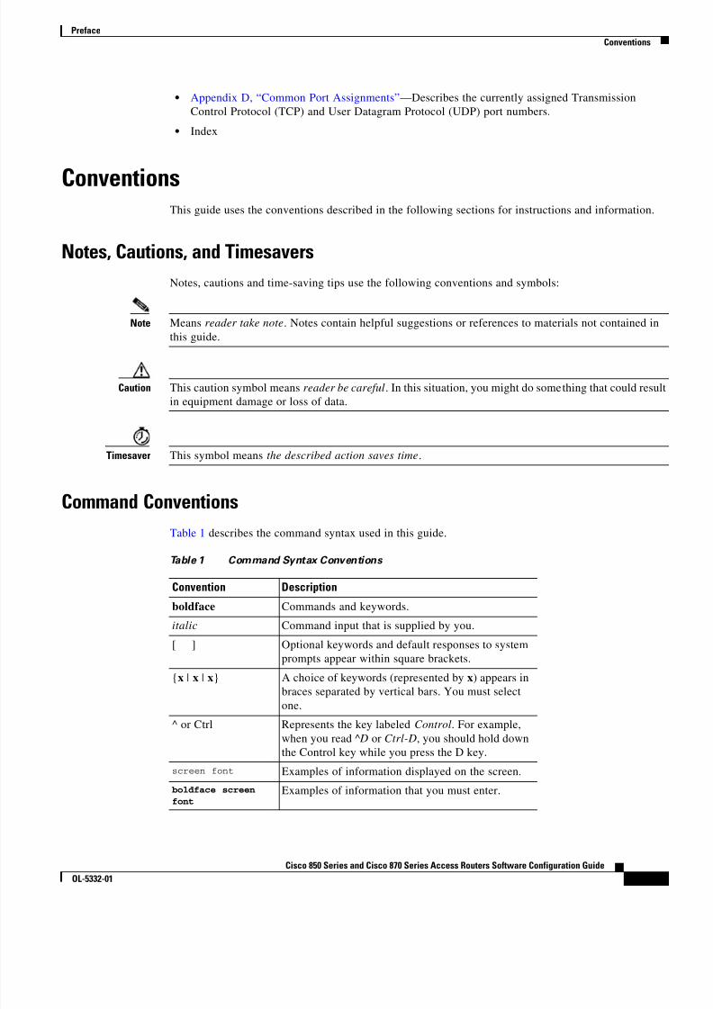
Command ConventionsTable 1 describes the command syntax used in this guide.
Table 1 Command Syntax Conventions
Convention Description
boldface Commands and keywords.
italic Command input that is supplied by you.
[ ] Optional keywords and default responses to systemprompts appear within square brackets.
{x | x | x} A choice of keywords (represented by x) appears inbraces separated by vertical bars. You must select
one.^ or Ctrl Represents the key labeled Control . For example,
when you read ^D or Ctrl-D , you should hold downthe Control key while you press the D key.
screen font Examples of information displayed on the screen.boldface screenfont
Examples of information that you must enter.

8/11/2019 Cisco 850 Series and Cisco 870 Series
http://slidepdf.com/reader/full/cisco-850-series-and-cisco-870-series 14/196
14Cisco 850 Series and Cisco 870 Series Access Routers Software Configuration Guide
OL-5332-01
Preface Related Documents
Related DocumentsThe following publications provide related information on these routers:
• Cisco 850 Series and Cisco 870 Series Access Routers Cabling and Setup Quick Start Guide
• Cisco 850 Series and Cisco 870 Series Access Routers Hardware Installation Guide • Cisco Router and Security Device Manager (SDM) Quick Start Guide
• Cisco Access Router Wireless Configuration Guide
• Upgrading Memory in Cisco 800 Series Routers
• Regulatory Compliance and Safety Information for Cisco 800 Series and SOHO Series Routers
• Declarations of Conformity and Regulatory Information for Cisco Access Products with 802.11a/b/gand 802.11b/g Radios
Obtaining Documentation and Submitting a Service RequestFor information on obtaining documentation, submitting a service request, and gathering additionalinformation, see the monthly What’s New in Cisco Product Documentation , which also lists all new andrevised Cisco technical documentation, at:
http://www.cisco.com/en/US/docs/general/whatsnew/whatsnew.html
Subscribe to the What’s New in Cisco Product Documentation as a Really Simple Syndication (RSS) feedand set content to be delivered directly to your desktop using a reader application. The RSS feeds are a freeservice and Cisco currently supports RSS Version 2.0.

8/11/2019 Cisco 850 Series and Cisco 870 Series
http://slidepdf.com/reader/full/cisco-850-series-and-cisco-870-series 15/196
P A R T 1
Getting Started

8/11/2019 Cisco 850 Series and Cisco 870 Series
http://slidepdf.com/reader/full/cisco-850-series-and-cisco-870-series 16/196

8/11/2019 Cisco 850 Series and Cisco 870 Series
http://slidepdf.com/reader/full/cisco-850-series-and-cisco-870-series 17/196
C H A P T E R
1-1Cisco 850 Series and Cisco 870 Series Access Routers Software Configuration Guide
OL-5332-01
1Basic Router Configuration
This chapter provides procedures for configuring the basic parameters of your Cisco router, includingglobal parameter settings, routing protocols, interfaces, and command-line access. It also describes thedefault configuration on startup.
Note Individual router models may not support every feature described throughout this guide. Features notsupported by a particular router are indicated whenever possible.
This chapter contains the following sections:
• Interface Port Labels
• Viewing the Default Configuration
• Information Needed for Configuration
• Configuring Basic Parameters
• Configuring Static Routes
• Configuring Dynamic Routes
• Configuring Enhanced IGRP
Each section includes a configuration example and verification steps, as available.
For complete information on how to access global configuration mode, see the “Entering GlobalConfiguration Mode” section in Appendix A, “Cisco IOS Basic Skills.” For more information on thecommands used in the following tables, see the Cisco IOS Release 12.3 documentation set.
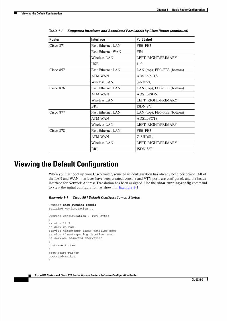
Interface Port LabelsTable 1-1 lists the interfaces supported for each router and their associated port labels on the equipment.
Table 1-1 Supported Interfaces and Associated Port Labels by Cisco Router
Router Interface Port Label
Cisco 851 Fast Ethernet LAN LAN (top), FE0–FE3 (bottom)
Fast Ethernet WAN WAN (top), FE4 (bottom)
Wireless LAN (no label)
8/11/2019 Cisco 850 Series and Cisco 870 Series
http://slidepdf.com/reader/full/cisco-850-series-and-cisco-870-series 18/196
1-2Cisco 850 Series and Cisco 870 Series Access Routers Software Configuration Guide
OL-5332-01
Chapter 1 Basic Router Configuration Viewing the Default Configuration
Viewing the Default ConfigurationWhen you first boot up your Cisco router, some basic configuration has already been performed. All ofthe LAN and WAN interfaces have been created, console and VTY ports are configured, and the insideinterface for Network Address Translation has been assigned. Use the show running-config commandto view the initial configuration, as shown in Example 1-1 .
Example 1-1 Cisco 851 Default Configuration on Startup
Router# show running-configBuilding configuration...
Current configuration : 1090 bytes!version 12.3no service padservice timestamps debug datetime msecservice timestamps log datetime msecno service password-encryption!hostname Router!boot-start-markerboot-end-marker!
Cisco 871 Fast Ethernet LAN FE0–FE3
Fast Ethernet WAN FE4
Wireless LAN LEFT, RIGHT/PRIMARY
USB 1–0
Cisco 857 Fast Ethernet LAN LAN (top), FE0–FE3 (bottom)
ATM WAN ADSLoPOTS
Wireless LAN (no label)
Cisco 876 Fast Ethernet LAN LAN (top), FE0–FE3 (bottom)
ATM WAN ADSLoISDN
Wireless LAN LEFT, RIGHT/PRIMARY
BRI ISDN S/T
Cisco 877 Fast Ethernet LAN LAN (top), FE0–FE3 (bottom)ATM WAN ADSLoPOTS
Wireless LAN LEFT, RIGHT/PRIMARY
Cisco 878 Fast Ethernet LAN FE0–FE3
ATM WAN G.SHDSL
Wireless LAN LEFT, RIGHT/PRIMARY
BRI ISDN S/T
Table 1-1 Supported Interfaces and Associated Port Labels by Cisco Router (continued)
Router Interface Port Label

8/11/2019 Cisco 850 Series and Cisco 870 Series
http://slidepdf.com/reader/full/cisco-850-series-and-cisco-870-series 19/196
1-3Cisco 850 Series and Cisco 870 Series Access Routers Software Configuration Guide
OL-5332-01
Chapter 1 Basic Router Configuration Viewing the Default Configuration
no aaa new-modelip subnet-zero!
ip cefip ips po max-events 100no ftp-server write-enable
!interface FastEthernet0 no ip address shutdown!interface FastEthernet1 no ip address shutdown!interface FastEthernet2 no ip address shutdown!interface FastEthernet3 no ip address
shutdown!interface FastEthernet4 no ip address duplex auto speed auto!interface Dot11Radio0 no ip address shutdown speed basic-1.0 basic-2.0 basic-5.5 6.0 9.0 basic-11.0 12.0 18.0 24.0 36.0 48.0 54.0 rts threshold 2312 station-role root!interface Vlan1 no ip address!ip classless!no ip http serverno ip http secure-server!control-plane!line con 0 no modem enable transport preferred all transport output allline aux 0 transport preferred all transport output allline vty 0 4 login transport preferred all transport input all transport output all!end
8/11/2019 Cisco 850 Series and Cisco 870 Series
http://slidepdf.com/reader/full/cisco-850-series-and-cisco-870-series 20/196
1-4Cisco 850 Series and Cisco 870 Series Access Routers Software Configuration Guide
OL-5332-01
Chapter 1 Basic Router Configuration Information Needed for Configuration
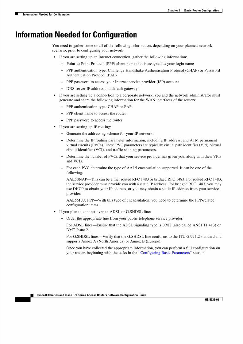
Information Needed for ConfigurationYou need to gather some or all of the following information, depending on your planned networkscenario, prior to configuring your network
• If you are setting up an Internet connection, gather the following information:
– Point-to-Point Protocol (PPP) client name that is assigned as your login name
– PPP authentication type: Challenge Handshake Authentication Protocol (CHAP) or PasswordAuthentication Protocol (PAP)
– PPP password to access your Internet service provider (ISP) account
– DNS server IP address and default gateways
• If you are setting up a connection to a corporate network, you and the network administrator mustgenerate and share the following information for the WAN interfaces of the routers: – PPP authentication type: CHAP or PAP – PPP client name to access the router
– PPP password to access the router • If you are setting up IP routing:
– Generate the addressing scheme for your IP network.
– Determine the IP routing parameter information, including IP address, and ATM permanentvirtual circuits (PVCs). These PVC parameters are typically virtual path identifier (VPI), virtualcircuit identifier (VCI), and traffic shaping parameters.
– Determine the number of PVCs that your service provider has given you, along with their VPIsand VCIs.
– For each PVC determine the type of AAL5 encapsulation supported. It can be one of thefollowing:
AAL5SNAP—This can be either routed RFC 1483 or bridged RFC 1483. For routed RFC 1483,the service provider must provide you with a static IP address. For bridged RFC 1483, you mayuse DHCP to obtain your IP address, or you may obtain a static IP address from your serviceprovider.
AAL5MUX PPP—With this type of encapsulation, you need to determine the PPP-relatedconfiguration items.
• If you plan to connect over an ADSL or G.SHDSL line:
– Order the appropriate line from your public telephone service provider.
For ADSL lines—Ensure that the ADSL signaling type is DMT (also called ANSI T1.413) orDMT Issue 2.
For G.SHDSL lines—Verify that the G.SHDSL line conforms to the ITU G.991.2 standard and
supports Annex A (North America) or Annex B (Europe).Once you have collected the appropriate information, you can perform a full configuration onyour router, beginning with the tasks in the “Configuring Basic Parameters” section.
8/11/2019 Cisco 850 Series and Cisco 870 Series
http://slidepdf.com/reader/full/cisco-850-series-and-cisco-870-series 21/196
1-5Cisco 850 Series and Cisco 870 Series Access Routers Software Configuration Guide
OL-5332-01
Chapter 1 Basic Router Configuration Configuring Basic Parameters
Configuring Basic ParametersTo configure the router, perform one or more of these tasks:
• Configure Global Parameters
• Configure Fast Ethernet LAN Interfaces • Configure WAN Interfaces
• Configuring a Loopback Interface
• Configuring Command-Line Access to the Router
A configuration example is presented with each task to show the network configuration followingcompletion of that task.
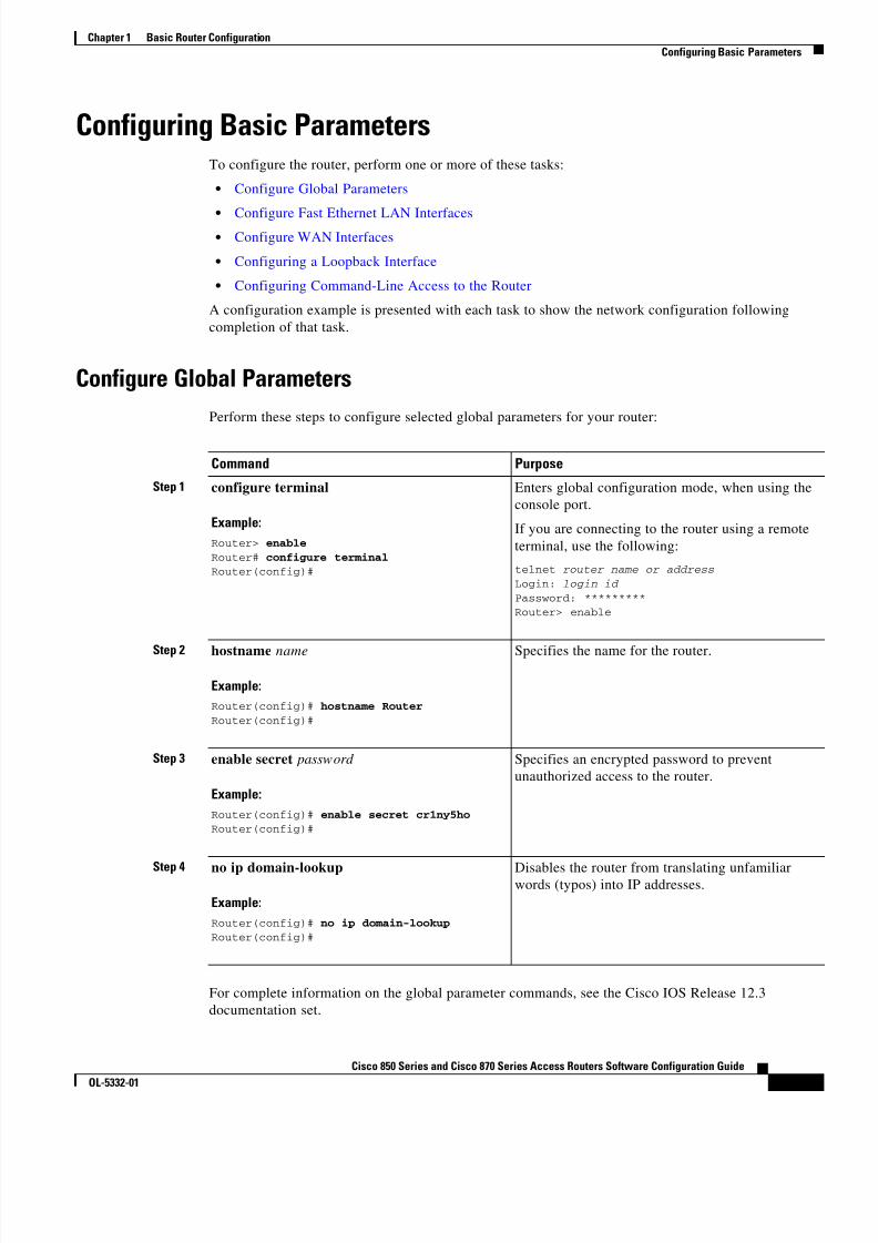
Configure Global ParametersPerform these steps to configure selected global parameters for your router:
Command Purpose
Step 1 configure terminal
Example:Router> enableRouter# configure terminalRouter(config)#
Enters global configuration mode, when using theconsole port.
If you are connecting to the router using a remoteterminal, use the following:
telnet router name or addressLogin: login id Password: *********Router> enable
Step 2 hostname name
Example:Router(config)# hostname RouterRouter(config)#
Specifies the name for the router.
Step 3 enable secret password
Example:Router(config)# enable secret cr1ny5hoRouter(config)#
Specifies an encrypted password to preventunauthorized access to the router.
Step 4 no ip domain-lookup
Example:Router(config)# no ip domain-lookupRouter(config)#
Disables the router from translating unfamiliarwords (typos) into IP addresses.
For complete information on the global parameter commands, see the Cisco IOS Release 12.3documentation set.

8/11/2019 Cisco 850 Series and Cisco 870 Series
http://slidepdf.com/reader/full/cisco-850-series-and-cisco-870-series 22/196
1-6Cisco 850 Series and Cisco 870 Series Access Routers Software Configuration Guide
OL-5332-01
Chapter 1 Basic Router Configuration Configuring Basic Parameters
Configure Fast Ethernet LAN InterfacesThe Fast Ethernet LAN interfaces on your router are automatically configured as part of the defaultVLAN and as such, they are not configured with individual addresses. Access is afforded through theVLAN. You may assign the interfaces to other VLANs if desired. For more information about creating
VLANs, see Chapter 5, “Configuring a LAN with DHCP and VLANs.”
Configure WAN InterfacesThe Cisco 851 and Cisco 871 routers each have one Fast Ethernet interface for WAN connection. TheCisco 857, Cisco 877, and Cisco 878 routers each have one ATM interface for WAN connection.
Based on the router model you have, configure the WAN interface(s) using one of the followingprocedures:
• Configure the Fast Ethernet WAN Interface
• Configure the ATM WAN Interface
Configure the Fast Ethernet WAN Interface
This procedure applies only to the Cisco 851 and Cisco 871 router models. Perform these steps toconfigure the Fast Ethernet interface, beginning in global configuration mode:
Command Purpose
Step 1 interface type number
Example:Router(config)# interface fastethernet 4Router(config-int)#
Enters the configuration mode for a FastEthernet WAN interface on the router.
Step 2 ip address ip-address mask
Example:Router(config-int)# ip address 192.168.12.2255.255.255.0Router(config-int)#
Sets the IP address and subnet mask for thespecified Fast Ethernet interface.
Step 3 no shutdown
Example:Router(config-int)# no shutdown
Router(config-int)#
Enables the Ethernet interface, changing itsstate from administratively down toadministratively up.
Step 4 exit
Example:Router(config-int)# exitRouter(config)#
Exits configuration mode for the Fast Ethernetinterface and returns to global configurationmode.

8/11/2019 Cisco 850 Series and Cisco 870 Series
http://slidepdf.com/reader/full/cisco-850-series-and-cisco-870-series 23/196
1-7Cisco 850 Series and Cisco 870 Series Access Routers Software Configuration Guide
OL-5332-01
Chapter 1 Basic Router Configuration Configuring Basic Parameters
Configure the ATM WAN Interface
This procedure applies only to the Cisco 857, Cisco 876, Cisco 877 and Cisco 878 models.
Perform these steps to configure the ATM interface, beginning in global configuration mode:
Command Purpose
Step 1 For the Cisco 878 model only:
controller dsl 0 mode atm exit
Example:Router(config)# controller dsl 0Router(config-controller)# mode atm Router(config-controller)# exitRouter(config)#
For routers using the G.SHDSL signaling, performthese commands. Ignore this step for routers usingADSL signaling.
Step 2 interface type number
Example:Router(config)# interface atm0Router(config-int)#
Identifies and enters the configuration mode for anATM interface.
Step 3 ip address ip-address mask
Example:Router(config-int)# ip address 10.10.10.100255.255.255.0Router(config-int)#
Sets the IP address and subnet mask for the ATMinterface.
Step 4 no shutdown
Example:Router(config-int)# no shutdownRouter(config-int)#
Enables the ATM 0 interface.
Step 5 exit
Example:Router(config-int)# exitRouter(config)#
Exits configuration mode for the ATM interfaceand returns to global configuration mode.
Configure the Wireless InterfaceThe wireless interface enables connection to the router through a wireless LAN connection. For moreinformation about configuring a wireless connection, see Chapter 9, “Configuring a Wireless LANConnection,” and the Cisco Access Router Wireless Configuration Guide .
8/11/2019 Cisco 850 Series and Cisco 870 Series
http://slidepdf.com/reader/full/cisco-850-series-and-cisco-870-series 24/196
1-8Cisco 850 Series and Cisco 870 Series Access Routers Software Configuration Guide
OL-5332-01
Chapter 1 Basic Router Configuration Configuring Basic Parameters
Configuring a Loopback InterfaceThe loopback interface acts as a placeholder for the static IP address and provides default routinginformation.
For complete information on the loopback commands, see the Cisco IOS Release 12.3documentation set.
Perform these steps to configure a loopback interface:
Command Purpose
Step 1 interface type number
Example:Router(config)# interface Loopback 0Router(config-int)#
Enters configuration mode for the loopbackinterface.
Step 2 ip address ip-address mask
Example:Router(config-int)# ip address 10.108.1.1255.255.255.0Router(config-int)#
Sets the IP address and subnet mask for theloopback interface.
Step 3 exit
Example:Router(config-int)# exitRouter(config)#
Exits configuration mode for the loopbackinterface and returns to global configurationmode.
Configuration Example
The loopback interface in this sample configuration is used to support Network Address Translation(NAT) on the virtual-template interface. This configuration example shows the loopback interfaceconfigured on the Fast Ethernet interface with an IP address of 10.10.10.100/24, which acts as a staticIP address. The loopback interface points back to virtual-template1, which has a negotiated IP address.
!interface loopback 0ip address 10.10.10.100 255.255.255.0 ( static IP address )ip nat outside!interface Virtual-Template1ip unnumbered loopback0no ip directed-broadcastip nat outside!

8/11/2019 Cisco 850 Series and Cisco 870 Series
http://slidepdf.com/reader/full/cisco-850-series-and-cisco-870-series 25/196
1-9Cisco 850 Series and Cisco 870 Series Access Routers Software Configuration Guide
OL-5332-01
Chapter 1 Basic Router Configuration Configuring Basic Parameters
Verifying Your Configuration
To verify that you have properly configured the loopback interface, enter the show interface loopbackcommand. You should see verification output similar to the following example.
Router# show interface loopback 0Loopback0 is up, line protocol is up
Hardware is Loopback Internet address is 10.10.10.100/24 MTU 1514 bytes, BW 8000000 Kbit, DLY 5000 usec,
reliability 255/255, txload 1/255, rxload 1/255 Encapsulation LOOPBACK, loopback not set Last input never, output never, output hang never Last clearing of "show interface" counters never Queueing strategy: fifo Output queue 0/0, 0 drops; input queue 0/75, 0 drops 5 minute input rate 0 bits/sec, 0 packets/sec 5 minute output rate 0 bits/sec, 0 packets/sec 0 packets input, 0 bytes, 0 no buffer Received 0 broadcasts, 0 runts, 0 giants, 0 throttles 0 input errors, 0 CRC, 0 frame, 0 overrun, 0 ignored, 0 abort 0 packets output, 0 bytes, 0 underruns
0 output errors, 0 collisions, 0 interface resets 0 output buffer failures, 0 output buffers swapped out
Another way to verify the loopback interface is to ping it:
Router# ping 10.10.10.100Type escape sequence to abort.Sending 5, 100-byte ICMP Echos to 10.10.10.100, timeout is 2 seconds:!!!!!Success rate is 100 percent (5/5), round-trip min/avg/max = 1/2/4 ms
Configuring Command-Line Access to the RouterPerform these steps to configure parameters to control access to the router, beginning in globalconfiguration mode.
Command Purpose
Step 1 line [aux | console | tty | vty ] line-number
Example:Router(config)# line console 0Router(config)#
Enters line configuration mode, and specifies thetype of line.
This example specifies a console terminal foraccess.
Step 2 password password
Example:Router(config)# password 5dr4Hepw3Router(config)#
Specifies a unique password for the consoleterminal line.

8/11/2019 Cisco 850 Series and Cisco 870 Series
http://slidepdf.com/reader/full/cisco-850-series-and-cisco-870-series 26/196
8/11/2019 Cisco 850 Series and Cisco 870 Series
http://slidepdf.com/reader/full/cisco-850-series-and-cisco-870-series 27/196
1-11Cisco 850 Series and Cisco 870 Series Access Routers Software Configuration Guide
OL-5332-01
Chapter 1 Basic Router Configuration Configuring Static Routes
Configuration Example
The following configuration shows the command-line access commands.
You do not need to input the commands marked “default.” These commands appear automatically in theconfiguration file generated when you use the show running-config command.
!line con 0exec-timeout 10 0password 4youreyesonlylogintransport input none (default)stopbits 1 (default)line vty 0 4password secretlogin!
Configuring Static RoutesStatic routes provide fixed routing paths through the network. They are manually configured on therouter. If the network topology changes, the static route must be updated with a new route. Static routesare private routes unless they are redistributed by a routing protocol. Configuring static routes on theCisco 850 and Cisco 870 series routers is optional.
Perform these steps to configure static routes, beginning in global configuration mode:
Command Purpose
Step 1 ip route prefix mask {ip-address | interface-type interface-number [ ip-address ]}
Example:Router(config)# ip route 192.168.1.0255.255.0.0 10.10.10.2Router(config)#
Specifies the static route for the IP packets.
For details about this command and additionalparameters that can be set, see the Cisco IOS IPCommand Reference, Volume 2 of 4: RoutingProtocols .
Step 2 end
Example:Router(config)# endRouter#
Exits router configuration mode, and entersprivileged EXEC mode.
For complete information on the static routing commands, see the Cisco IOS Release 12.3documentation set. For more general information on static routing, see Appendix B, “Concepts.”

8/11/2019 Cisco 850 Series and Cisco 870 Series
http://slidepdf.com/reader/full/cisco-850-series-and-cisco-870-series 28/196
1-12Cisco 850 Series and Cisco 870 Series Access Routers Software Configuration Guide
OL-5332-01
Chapter 1 Basic Router Configuration Configuring Dynamic Routes
Configuration ExampleIn the following configuration example, the static route sends out all IP packets with a destination IPaddress of 192.168.1.0 and a subnet mask of 255.255.255.0 on the Fast Ethernet interface to anotherdevice with an IP address of 10.10.10.2. Specifically, the packets are sent to the configured PVC.
You do not need to enter the commands marked “( default ).” These commands appear automatically inthe configuration file generated when you use the show running-config command.
!ip classless ( default )ip route 192.168.1.0 255.255.255.0 10.10.10.2!
Verifying Your ConfigurationTo verify that you have properly configured static routing, enter the show ip route command and lookfor static routes signified by the “S.”
You should see verification output similar to the following example.Router# show ip routeCodes: C - connected, S - static, R - RIP, M - mobile, B - BGP D - EIGRP, EX - EIGRP external, O - OSPF, IA - OSPF inter area N1 - OSPF NSSA external type 1, N2 - OSPF NSSA external type 2 E1 - OSPF external type 1, E2 - OSPF external type 2 i - IS-IS, su - IS-IS summary, L1 - IS-IS level-1, L2 - IS-IS level-2 ia - IS-IS inter area, * - candidate default, U - per-user static route o - ODR, P - periodic downloaded static route
Gateway of last resort is not set
10.0.0.0/24 is subnetted, 1 subnetsC 10.108.1.0 is directly connected, Loopback0S* 0.0.0.0/0 is directly connected, FastEthernet0
Configuring Dynamic RoutesIn dynamic routing, the network protocol adjusts the path automatically, based on network traffic ortopology. Changes in dynamic routes are shared with other routers in the network.
The Cisco routers can use IP routing protocols, such as Routing Information Protocol (RIP) or EnhancedInterior Gateway Routing Protocol (EIGRP), to learn routes dynamically. You can configure either ofthese routing protocols on your router.

8/11/2019 Cisco 850 Series and Cisco 870 Series
http://slidepdf.com/reader/full/cisco-850-series-and-cisco-870-series 29/196
1-13Cisco 850 Series and Cisco 870 Series Access Routers Software Configuration Guide
OL-5332-01
Chapter 1 Basic Router Configuration Configuring Dynamic Routes
Configuring RIPPerform these steps to configure the RIP routing protocol on the router, beginning in globalconfiguration mode:
Command Task
Step 1 router rip
Example:Router> configure terminalRouter(config)# router ripRouter(config-router)#
Enters router configuration mode, and enables RIPon the router.
Step 2 version { 1 | 2}
Example:Router(config-router)# version 2
Router(config-router)#
Specifies use of RIP version 1 or 2.
Step 3 network ip-address
Example:Router(config-router)# network 192.168.1.1Router(config-router)# network 10.10.7.1Router(config-router)#
Specifies a list of networks on which RIP is to beapplied, using the address of the network ofdirectly connected networks.
Step 4 no auto-summary
Example:
Router(config-router)# no auto-summaryRouter(config-router)#
Disables automatic summarization of subnet routesinto network-level routes. This allows subprefixrouting information to pass across classful networkboundaries.
Step 5 end
Example:Router(config-router)# endRouter#
Exits router configuration mode, and entersprivileged EXEC mode.
For complete information on the dynamic routing commands, see the Cisco IOS Release 12.3documentation set. For more general information on RIP, see Appendix B, “Concepts.”

8/11/2019 Cisco 850 Series and Cisco 870 Series
http://slidepdf.com/reader/full/cisco-850-series-and-cisco-870-series 30/196
1-14Cisco 850 Series and Cisco 870 Series Access Routers Software Configuration Guide
OL-5332-01
Chapter 1 Basic Router Configuration Configuring Enhanced IGRP
Configuration Example
The following configuration example shows RIP version 2 enabled in IP network 10.0.0.0 and192.168.1.0.
Execute the show running-config command from privileged EXEC mode to see this configuration.
!router rip version 2 network 10.0.0.0 network 192.168.1.0 no auto-summary!
Verifying Your Configuration
To verify that you have properly configured RIP, enter the show ip route command and look for RIProutes signified by “R.” You should see a verification outpu t like the example shown below.
Router# show ip routeCodes: C - connected, S - static, R - RIP, M - mobile, B - BGP D - EIGRP, EX - EIGRP external, O - OSPF, IA - OSPF inter area N1 - OSPF NSSA external type 1, N2 - OSPF NSSA external type 2 E1 - OSPF external type 1, E2 - OSPF external type 2 i - IS-IS, su - IS-IS summary, L1 - IS-IS level-1, L2 - IS-IS level-2 ia - IS-IS inter area, * - candidate default, U - per-user static route o - ODR, P - periodic downloaded static route
Gateway of last resort is not set
10.0.0.0/24 is subnetted, 1 subnetsC 10.108.1.0 is directly connected, Loopback0R 3.0.0.0/8 [120/1] via 2.2.2.1, 00:00:02, Ethernet0/0
Configuring Enhanced IGRPPerform these steps to configure Enhanced IGRP (EIGRP), beginning in global configuration mode:
Command PurposeStep 1 router eigrp as-number
Example:Router(config)# router eigrp 109
Router(config)#
Enters router configuration mode, and enablesEIGRP on the router. The autonomous-systemnumber identifies the route to other EIGRP routersand is used to tag the EIGRP information.

8/11/2019 Cisco 850 Series and Cisco 870 Series
http://slidepdf.com/reader/full/cisco-850-series-and-cisco-870-series 31/196
1-15Cisco 850 Series and Cisco 870 Series Access Routers Software Configuration Guide
OL-5332-01
Chapter 1 Basic Router Configuration Configuring Enhanced IGRP
For complete information on the IP EIGRP commands, see the Cisco IOS Release 12.3 documentationset. For more general information on EIGRP concepts, see Appendix B, “Concepts.”
Configuration ExampleThe following configuration example shows the EIGRP routing protocol enabled in IP networks192.145.1.0 and 10.10.12.115. The EIGRP autonomous system number is 109.
Execute the show running-config command from privileged EXEC mode to see this configuration.
!router eigrp 109
network 192.145.1.0network 10.10.12.115
!
Verifying Your ConfigurationTo verify that you have properly configured IP EIGRP, enter the show ip route command, and look forEIGRP routes indicated by “D.” You should see verification output similar to the following example.
Router# show ip routeCodes: C - connected, S - static, R - RIP, M - mobile, B - BGP D - EIGRP, EX - EIGRP external, O - OSPF, IA - OSPF inter area N1 - OSPF NSSA external type 1, N2 - OSPF NSSA external type 2 E1 - OSPF external type 1, E2 - OSPF external type 2 i - IS-IS, su - IS-IS summary, L1 - IS-IS level-1, L2 - IS-IS level-2 ia - IS-IS inter area, * - candidate default, U - per-user static route o - ODR, P - periodic downloaded static route
Gateway of last resort is not set
10.0.0.0/24 is subnetted, 1 subnetsC 10.108.1.0 is directly connected, Loopback0D 3.0.0.0/8 [90/409600] via 2.2.2.1, 00:00:02, Ethernet0/0
Step 2 network ip-address
Example:Router(config)# network 192.145.1.0
Router(config)# network 10.10.12.115Router(config)#
Specifies a list of networks on which EIGRP is tobe applied, using the IP address of the network ofdirectly connected networks.
Step 3 end
Example:Router(config-router)# endRouter#
Exits router configuration mode, and entersprivileged EXEC mode.
Command Purpose

8/11/2019 Cisco 850 Series and Cisco 870 Series
http://slidepdf.com/reader/full/cisco-850-series-and-cisco-870-series 32/196
1-16Cisco 850 Series and Cisco 870 Series Access Routers Software Configuration Guide
OL-5332-01
Chapter 1 Basic Router Configuration Configuring Enhanced IGRP

8/11/2019 Cisco 850 Series and Cisco 870 Series
http://slidepdf.com/reader/full/cisco-850-series-and-cisco-870-series 33/196
P A R T 2
Configuring Your Router for Ethernet andDSL Access

8/11/2019 Cisco 850 Series and Cisco 870 Series
http://slidepdf.com/reader/full/cisco-850-series-and-cisco-870-series 34/196

8/11/2019 Cisco 850 Series and Cisco 870 Series
http://slidepdf.com/reader/full/cisco-850-series-and-cisco-870-series 35/196
C H A P T E R
2-1Cisco 850 Series and Cisco 870 Series Access Routers Software Configuration Guide
OL-5332-01
2Sample Network Deployments
This part of the software configuration guide presents a variety of possible Ethernet- and DigitalSubscriber Line (DSL)-based network configurations using the Cisco 850 and Cisco 870 series accessrouters. Each scenario is described with a network topology, a step-by-step procedure that is used toimplement the network configuration, and a configuration example that shows the results of theconfiguration. The Cisco 851 and Cisco 871 router models can be used in the Ethernet-based scenarios
and the Cisco 857, Cisco 876, Cisco 877, and Cisco 878 router models can be used in the DSL-basedscenarios.
The first network scenario provides a simple network configuration: point-to-point protocol (PPP) overthe WAN interface with Network Address Translation (NAT). Each successive scenario builds on theprevious scenario by configuring another key feature.
The scenarios do not address all of the possible network needs; instead, they provide models on whichyou can pattern your network. You can choose not to use features presented in the examples, or you canadd or substitute features that better suit your needs.
Note To verify that a specific feature is compatible with your router, you can use the Software Advisor tool.You can access this tool at www.cisco.com > Technical Support & Documentation > Tools &
Resources with your Cisco username and password.
For Ethernet-Based Network Deployments
Use the following configuration examples to assist you in configuring your router for Ethernet-basednetworks.
• Chapter 3, “Configuring PPP over Ethernet with NAT”
• Chapter 5, “Configuring a LAN with DHCP and VLANs”
• Chapter 6, “Configuring a VPN Using Easy VPN and an IPSec Tunnel”
• Chapter 7, “Configuring VPNs Using an IPSec Tunnel and Generic Routing Encapsulation”
• Chapter 8, “Configuring a Simple Firewall”
For DSL-Based Network Deployments
Use the following configuration examples to assist you in configuring your router for DSL-basednetworks.
• Chapter 4, “Configuring PPP over ATM with NAT”
• Chapter 5, “Configuring a LAN with DHCP and VLANs”
• Chapter 6, “Configuring a VPN Using Easy VPN and an IPSec Tunnel”

8/11/2019 Cisco 850 Series and Cisco 870 Series
http://slidepdf.com/reader/full/cisco-850-series-and-cisco-870-series 36/196
8/11/2019 Cisco 850 Series and Cisco 870 Series
http://slidepdf.com/reader/full/cisco-850-series-and-cisco-870-series 37/196
C H A P T E R
3-1Cisco 850 Series and Cisco 870 Series Access Routers Software Configuration Guide
OL-5332-01
1 2 1 7 5 3
2
3
5
6
1
7
4
3Configuring PPP over Ethernet with NAT
The Cisco 851 and Cisco 871access routers support Point-to-Point Protocol over Ethernet (PPPoE)clients and network address translation (NAT).
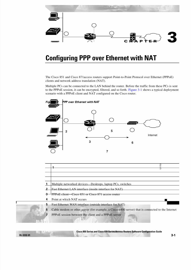
Multiple PCs can be connected to the LAN behind the router. Before the traffic from these PCs is sentto the PPPoE session, it can be encrypted, filtered, and so forth. Figure 3-1 shows a typical deployment
scenario with a PPPoE client and NAT configured on the Cisco router.
Figure 3-1 PPP over Ethernet with NAT
1 2 1 7 5 3
2
3
5
6
1
7
4
Internet
1 Multiple networked devices—Desktops, laptop PCs, switches
2 Fast Ethernet LAN interface (inside interface for NAT)3 PPPoE client—Cisco 851 or Cisco 871 access router
4 Point at which NAT occurs
5 Fast Ethernet WAN interface (outside interface for NAT)
6 Cable modem or other server (for example, a Cisco 6400 server) that is connected to the Internet
7 PPPoE session between the client and a PPPoE server
8/11/2019 Cisco 850 Series and Cisco 870 Series
http://slidepdf.com/reader/full/cisco-850-series-and-cisco-870-series 38/196
3-2Cisco 850 Series and Cisco 870 Series Access Routers Software Configuration Guide
OL-5332-01
Chapter 3 Configuring PPP over Ethernet with NAT Configure the Virtual Private Dialup Network Group Number
PPPoE
The PPPoE Client feature on the router provides PPPoE client support on Ethernet interfaces. A dialerinterface must be used for cloning virtual access. Multiple PPPoE client sessions can be configured onan Ethernet interface, but each session must use a separate dialer interface and a separate dialer pool.
A PPPoE session is initiated on the client side by the Cisco 850 or Cisco 870 series router.An established
PPPoE client session can be terminated in one of two ways: • By entering the clear vpdn tunnel pppoe command. The PPPoE client session terminates, and the
PPPoE client immediately tries to reestablish the session. This also occurs if the session has atimeout.
• By entering the no pppoe-client dial-pool number command to clear the session. The PPPoE clientdoes not attempt to reestablish the session.
NAT
NAT (represented as the dashed line at the edge of the Cisco router) signifies two addressing domainsand the inside source address. The source list defines how the packet travels through the network.
Configuration Tasks
Perform the following tasks to configure this network scenario:
• Configure the Virtual Private Dialup Network Group Number
• Configure the Fast Ethernet WAN Interfaces
• Configure the Dialer Interface
• Configure Network Address Translation
An example showing the results of these configuration tasks is shown in the “Configuration Example”section on page 3-8 .
Configure the Virtual Private Dialup Network Group NumberConfiguring a virtual private dialup network (VPDN) enables multiple clients to communicate throughthe router by way of a single IP address.
Complete the following steps to configure a VPDN, starting from the global configuration mode. See the“Configure Global Parameters” section on page 1-5 for details about entering this mode.
Command or Action Purpose
Step 1 vpdn enable
Example:Router(config)# vpdn enableRouter(config)#
Enables VPDN on the router.
Step 2 vpdn-group name
Example:Router(config)# vpdn-group 1Router(config-vpdn)#
Creates and associates a VPDN group with acustomer or VPDN profile.

8/11/2019 Cisco 850 Series and Cisco 870 Series
http://slidepdf.com/reader/full/cisco-850-series-and-cisco-870-series 39/196
3-3Cisco 850 Series and Cisco 870 Series Access Routers Software Configuration Guide
OL-5332-01
Chapter 3 Configuring PPP over Ethernet with NAT Configure the Fast Ethernet WAN Interfaces
Configure the Fast Ethernet WAN InterfacesIn this scenario, the PPPoE client (your Cisco router) communicates over a 10/100 Mbps-Ethernetinterface on both the inside and the outside.
Perform these steps to configure the Fast Ethernet WAN interfaces, starting in global configurationmode:
Step 3 request-dialin
Example:Router(config-vpdn)# request-dialin
Router(config-vpdn-req-in)#
Creates a request-dialin VPDN subgroup,indicating the dialing direction, and initiates thetunnel.
Step 4 protocol { l2tp | pppoe }
Example:Router(config-vpdn-req-in)# protocol pppoeRouter(config-vpdn-req-in)#
Specifies the type of sessions the VPDN subgroupcan establish.
Step 5 exit
Example:Router(config-vpdn-req-in)# exitRouter(config-vpdn)#
Exits request-dialin VPDN group configuration.
Step 6 exit
Example:Router(config-vpdn)# exitRouter(config)#
Exits VPDN configuration, returning to globalconfiguration mode.
Command or Action Purpose
Command Purpose
Step 1 interface type number
Example:Router(config)# interface fastethernet 4Router(config-if)#
Enters interface configuration mode for aFast Ethernet WAN interface.
Step 2 pppoe-client dial-pool-number number
Example:Router(config-if)# pppoe-clientdial-pool-number 1Router(config-if)#
Configures the PPPoE client and specifies thedialer interface to use for cloning.

8/11/2019 Cisco 850 Series and Cisco 870 Series
http://slidepdf.com/reader/full/cisco-850-series-and-cisco-870-series 40/196

8/11/2019 Cisco 850 Series and Cisco 870 Series
http://slidepdf.com/reader/full/cisco-850-series-and-cisco-870-series 41/196

8/11/2019 Cisco 850 Series and Cisco 870 Series
http://slidepdf.com/reader/full/cisco-850-series-and-cisco-870-series 42/196
8/11/2019 Cisco 850 Series and Cisco 870 Series
http://slidepdf.com/reader/full/cisco-850-series-and-cisco-870-series 43/196
3-7Cisco 850 Series and Cisco 870 Series Access Routers Software Configuration Guide
OL-5332-01
Chapter 3 Configuring PPP over Ethernet with NAT Configure Network Address Translation
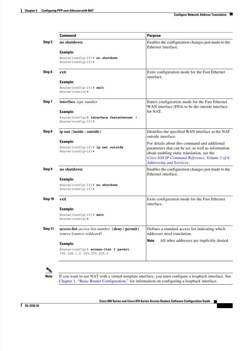
Note If you want to use NAT with a virtual-template interface, you must configure a loopback interface. SeeChapter 1, “Basic Router Configuration,” for information on configuring a loopback interface.
Step 5 no shutdown
Example:Router(config-if)# no shutdown
Router(config-if)#
Enables the configuration changes just made to theEthernet interface.
Step 6 exit
Example:Router(config-if)# exitRouter(config)#
Exits configuration mode for the Fast Ethernetinterface.
Step 7 interface type number
Example:Router(config)# interface fastethernet 4Router(config-if)#
Enters configuration mode for the Fast EthernetWAN interface (FE4) to be the outside interfacefor NAT.
Step 8 ip nat { inside | outside }
Example:Router(config-if)# ip nat outsideRouter(config-if)#
Identifies the specified WAN interface as the NAToutside interface.
For details about this command and additionalparameters that can be set, as well as informationabout enabling static translation, see theCisco IOS IP Command Reference, Volume 1 of 4:
Addressing and Services .
Step 9 no shutdown
Example:
Router(config-if)# no shutdownRouter(config-if)#
Enables the configuration changes just made to theEthernet interface.
Step 10 exit
Example:Router(config-if)# exitRouter(config)#
Exits configuration mode for the Fast Ethernetinterface.
Step 11 access-list access-list-number {deny | permit }source [source-wildcard ]
Example:Router(config)# access-list 1 permit 192.168.1.0 255.255.255.0
Defines a standard access list indicating whichaddresses need translation.
Note All other addresses are implicitly denied.
Command Purpose

8/11/2019 Cisco 850 Series and Cisco 870 Series
http://slidepdf.com/reader/full/cisco-850-series-and-cisco-870-series 44/196
3-8Cisco 850 Series and Cisco 870 Series Access Routers Software Configuration Guide
OL-5332-01
Chapter 3 Configuring PPP over Ethernet with NAT Configuration Example
For complete information on the NAT commands, see the Cisco IOS Release 12.3 documentation set.For more general information on NAT concepts, see Appendix B, “Concepts.”
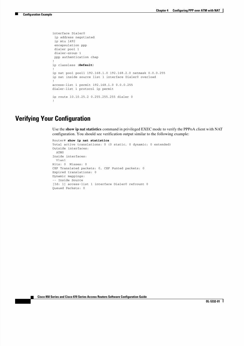
Configuration ExampleThe following configuration example shows a portion of the configuration file for the PPPoE scenariodescribed in this chapter.
The VLAN interface has an IP address of 192.168.1.1 with a subnet mask of 255.255.255.0. NAT isconfigured for inside and outside
Note Commands marked by “ (default) ” are generated automatically when you run the show running-config command.
vpdn enable vpdn-group 1 request-dialin protocol pppoe ! interface vlan 1 ip address 192.168.1.1 255.255.255.0 no ip directed-broadcast (default) ip nat insideinterface FastEthernet 4 no ip addressno ip directed-broadcast (default) ip nat outside pppoe enable group global pppoe-client dial-pool-number 1 no sh! interface dialer 1
ip address negotiated ip mtu 1492 encapsulation ppp ppp authentication chap dialer pool 1 dialer-group 1 ! dialer-list 1 protocol ip permit ip nat inside source list 1 interface dialer 0 overload ip classless (default) ip route 10.10.25.2 255.255.255.255 dialer 0ip nat pool pool1 192.168.1.0 192.168.2.0 netmask 255.255.252.0 ip nat inside source list acl1 pool pool1!

8/11/2019 Cisco 850 Series and Cisco 870 Series
http://slidepdf.com/reader/full/cisco-850-series-and-cisco-870-series 45/196
3-9Cisco 850 Series and Cisco 870 Series Access Routers Software Configuration Guide
OL-5332-01
Chapter 3 Configuring PPP over Ethernet with NAT Configuration Example
Verifying Your ConfigurationUse the show ip nat statistics command in privileged EXEC mode to verify the PPPoE with NATconfiguration. You should see verification output similar to the following example:
Router# show ip nat statistics
Total active translations: 0 (0 static, 0 dynamic; 0 extended)Outside interfaces: FastEthernet4Inside interfaces: Vlan1Hits: 0 Misses: 0CEF Translated packets: 0, CEF Punted packets: 0Expired translations: 0Dynamic mappings:-- Inside Source[Id: 1] access-list 1 interface Dialer0 refcount 0Queued Packets: 0

8/11/2019 Cisco 850 Series and Cisco 870 Series
http://slidepdf.com/reader/full/cisco-850-series-and-cisco-870-series 46/196

8/11/2019 Cisco 850 Series and Cisco 870 Series
http://slidepdf.com/reader/full/cisco-850-series-and-cisco-870-series 47/196
C H A P T E R
4-1Cisco 850 Series and Cisco 870 Series Access Routers Software Configuration Guide
OL-5332-01
1 2 1 7 5 3
2
3
5
6
1
7
4
4Configuring PPP over ATM with NAT
The Cisco 857, Cisco 876, Cisco 877, and Cisco 878 access routers support Point-to-Point Protocol overAsynchronous Transfer Mode (PPPoA) clients and network address translation (NAT).
Multiple PCs can be connected to the LAN behind the router. Before traffic from the PCs is sent to thePPPoA session, it can be encrypted, filtered, and so forth. PPP over ATM provides a network solution
with simplified address handling and straight user verification like a dial network. Figure 4-1 shows atypical deployment scenario with a PPPoA client and NAT configured on the Cisco router. This scenariouses a single static IP address for the ATM connection.
Figure 4-1 PPP over ATM with NAT
9 2 3 4 0
2
3
5
1
6
4
ISP
1 Small business with multiple networked devices—desktops, laptop PCs, switches
2 Fast Ethernet LAN interface (inside interface for NAT, 192.168.1.1/24)
3 PPPoA Client—Cisco 857, Cisco 876, Cisco 877, or Cisco 878 router
4 Point at which NAT occurs
5 ATM WAN interface (outside interface for NAT)
6 PPPoA session between the client and a PPPoA server at the ISP

8/11/2019 Cisco 850 Series and Cisco 870 Series
http://slidepdf.com/reader/full/cisco-850-series-and-cisco-870-series 48/196
4-2Cisco 850 Series and Cisco 870 Series Access Routers Software Configuration Guide
OL-5332-01
Chapter 4 Configuring PPP over ATM with NAT
In this scenario, the small business or remote user on the Fast Ethernet LAN can connect to an Internetservice provider (ISP) using the following protocols on the WAN connection:
• Asymmetric digital subscriber line (ADSL) over plain old telephone service (POTS) using theCisco 857 or Cisco 877 router
• ADSL over integrated services digital network (ISDN) using the Cisco 876 router
• Single-pair high-speed digital subscriber line (G.SHDSL) using the Cisco 878 router
The Fast Ethernet interface carries the data packet through the LAN and off-loads it to the PPPconnection on the ATM interface. The ATM traffic is encapsulated and sent over the ADSL, ISDN, orG.SHDSL lines. The dialer interface is used to connect to the ISP.
PPPoA
The PPPoA Client feature on the router provides PPPoA client support on ATM interfaces. A dialerinterface must be used for cloning virtual access. Multiple PPPoA client sessions can be configured onan ATM interface, but each session must use a separate dialer interface and a separate dialer pool.
A PPPoA session is initiated on the client side by the Cisco 850 or Cisco 870 series router.
NATNAT (represented as the dashed line at the edge of the Cisco router) signifies two addressing domainsand the inside source address. The source list defines how the packet travels through the network.
Configuration Tasks
Perform the following tasks to configure this network scenario:
• Configure the Dialer Interface
• Configure the ATM WAN Interface
• Configure DSL Signaling Protocol
• Configure Network Address Translation
An example showing the results of these configuration tasks is shown in the “Configuration Example”section on page 4-11 .

8/11/2019 Cisco 850 Series and Cisco 870 Series
http://slidepdf.com/reader/full/cisco-850-series-and-cisco-870-series 49/196
4-3Cisco 850 Series and Cisco 870 Series Access Routers Software Configuration Guide
OL-5332-01
Chapter 4 Configuring PPP over ATM with NAT Configure the Dialer Interface
Configure the Dialer InterfaceThe dialer interface indicates how to handle traffic from the clients, including, for example, defaultrouting information, the encapsulation protocol, and the dialer pool to use. It is also used for cloningvirtual access. Multiple PPPoA client sessions can be configured on an ATM interface, but each session
must use a separate dialer interface and a separate dialer pool.Perform these steps to configure a dialer interface for the ATM interface on the router, starting in globalconfiguration mode.
Command Purpose
Step 1 interface dialer dialer-rotary-group-number
Example:Router(config)# interface dialer 0Router(config-if)#
Creates a dialer interface (numbered 0–255), andenters into interface configuration mode.
Step 2 ip address negotiated
Example:Router(config-if)# ip address negotiatedRouter(config-if)#
Specifies that the IP address for the dialerinterface is obtained through PPP/IPCP (IPControl Protocol) address negotiation.
Step 3 ip mtu bytes
Example:Router(config-if)# ip mtu 4470Router(config-if)#
Sets the size of the IP maximum transmission unit(MTU). The default minimum is 128 bytes. Themaximum for ATM is 4470 bytes.
Step 4 encapsulation encapsulation-type
Example:Router(config-if)# encapsulation pppRouter(config-if)#
Sets the encapsulation type to PPP for the datapackets being transmitted and received.
Step 5 ppp authentication { protocol1 [ protocol2 ...]}
Example:Router(config-if)# ppp authentication chapRouter(config-if)#
Sets the PPP authentication method.
The example applies the Challenge HandshakeAuthentication Protocol (CHAP).
For details about this command and additionalparameters that can be set, see the Cisco IOSSecurity Command Reference.
Step 6 dialer pool number
Example:Router(config-if)# dialer pool 1Router(config-if)#
Specifies the dialer pool to use to connect to aspecific destination subnetwork.

8/11/2019 Cisco 850 Series and Cisco 870 Series
http://slidepdf.com/reader/full/cisco-850-series-and-cisco-870-series 50/196

8/11/2019 Cisco 850 Series and Cisco 870 Series
http://slidepdf.com/reader/full/cisco-850-series-and-cisco-870-series 51/196

8/11/2019 Cisco 850 Series and Cisco 870 Series
http://slidepdf.com/reader/full/cisco-850-series-and-cisco-870-series 52/196
4-6Cisco 850 Series and Cisco 870 Series Access Routers Software Configuration Guide
OL-5332-01
Chapter 4 Configuring PPP over ATM with NAT Configure DSL Signaling Protocol
Configure DSL Signaling ProtocolDSL signaling must be configured on the ATM interface for connection to your ISP. The Cisco 857 andCisco 877 routers support ADSL signaling over POTS, the Cisco 876 supports ADSL signaling overISDN, and the Cisco 878 supports SHDSL signaling. Based on the router you are configuring, see oneof the following sections to configure the appropriate DSL signaling protocol.
• Configuring ADSL
• Configuring SHDSL
Configuring ADSLThe default configuration for ADSL signaling is shown in Table 4-1 .
Table 4-1 Default ADSL Configuration
Attribute Description Default Value
Operating mode Specifies the operating mode of the digital subscriber line(DSL) for an ATM interface.
• ADSL over POTS—ANSI or ITU full rate, orautomatic selection.
• ADSL over ISDN—ITU full rate, ETSI, orautomatic selection.
Auto
Loss of margin Specifies the number of times a loss of margin may occur. —
Training log Toggles between enabling the training log and disabling thetraining log.
Disabled
Step 5 no shutdown
Example:Router(config-if-atm-vc)# no shutdown
Router(config-if)#
Enables interface and configuration changes justmade to the ATM interface.
Step 6 exit
Example:Router(config-if)# exitRouter(config)#
Exits configuration mode for the ATM interface.
Command Purpose

8/11/2019 Cisco 850 Series and Cisco 870 Series
http://slidepdf.com/reader/full/cisco-850-series-and-cisco-870-series 53/196
4-7Cisco 850 Series and Cisco 870 Series Access Routers Software Configuration Guide
OL-5332-01
Chapter 4 Configuring PPP over ATM with NAT Configure DSL Signaling Protocol
If you wish to change any of these settings, use one of the following commands in global configurationmode.
• dsl operating-mode (from the ATM interface configuration mode)
• dsl lom integer
• dsl enable-training-log
See the Cisco IOS Wide-Area Networking Command Reference for details of these commands.
Verify the Configuration
You can verify that the configuration is set the way you want by using the show dsl interface atmcommand from privileged EXEC mode.
Configuring SHDSLComplete the following steps to configure the DSL controller in your router to use SHDSL signaling,
beginning in global configuration mode.
Command Purpose
Step 1 controller dsl port
Example:Router(config)# controller dsl 0Router(config-controller)#
Enters the configuration mode for the DSLcontroller.
Step 2 line-term { co | cpe }
Example:Router(config-controller)# line-term coRouter(config-controller)#
Specifies if the DSL line is terminated at a centraloffice (CO) or at customer premises equipment
(CPE).
Step 3 exit
Example:Router(config-controller)# exitRouter(config)#
Exits controller configuration mode, returning toglobal configuration mode.
Step 4 mode protocol
Example:Router(config)# mode atm Router(config-controller)#
Specifies the mode of the DSL controller andenters controller configuration mode.
Step 5 line-mode {4-wire | 2-wire }
Example:Router(config-controller)# line-mode 4-wireRouter(config-controller)#
Specifies whether this DSL connection isoperating in 2-wire or 4-wire mode.

8/11/2019 Cisco 850 Series and Cisco 870 Series
http://slidepdf.com/reader/full/cisco-850-series-and-cisco-870-series 54/196

8/11/2019 Cisco 850 Series and Cisco 870 Series
http://slidepdf.com/reader/full/cisco-850-series-and-cisco-870-series 55/196
4-9Cisco 850 Series and Cisco 870 Series Access Routers Software Configuration Guide
OL-5332-01
Chapter 4 Configuring PPP over ATM with NAT Configure Network Address Translation
Receiver Gain: 22.5420 dBSNR Sampling: 36.8590 dBDying Gasp: Present
Configure Network Address TranslationNetwork Address Translation (NAT) translates packets from addresses that match a standard access list,using global addresses allocated by the dialer interface. Packets that enter the router through the insideinterface, packets sourced from the router, or both are checked against the access list for possible addresstranslation. You can configure NAT for either static or dynamic address translations.
Perform these steps to configure the outside ATM WAN interface with dynamic NAT, beginning in globalconfiguration mode:
Command Purpose
Step 1 ip nat pool name start-ip end-ip {netmask
netmask | prefix-length prefix-length }
Example:Router(config)# ip nat pool pool1192.168.1.0 192.168.2.0 netmask255.255.255.0Router(config)#
Creates pool of global IP addresses for NAT.
Step 2 ip nat inside source {list access-list-number }{interface type number | pool name } [ overload ]
Example 1:Router(config)# ip nat inside source list 1interface dialer 0 overload
or
Example 2:Router(config)# ip nat inside source listacl1 pool pool1
Enables dynamic translation of addresses on theinside interface.
The first example shows the addresses permittedby the access list 1 to be translated to one of the
addresses specified in the dialer interface 0 .The second example shows the addressespermitted by access list acl1 to be translated to oneof the addresses specified in the NAT pool pool1 .
For details about this command and additionalparameters that can be set, as well as informationabout enabling static translation, see theCisco IOS IP Command Reference, Volume 1 of 4:
Addressing and Services .
Step 3 interface type number
Example:Router(config)# interface vlan 1Router(config-if)#
Enters configuration mode for the VLAN (onwhich the Fast Ethernet LAN interfaces[FE0–FE3] reside) to be the inside interface forNAT.
8/11/2019 Cisco 850 Series and Cisco 870 Series
http://slidepdf.com/reader/full/cisco-850-series-and-cisco-870-series 56/196
4-10Cisco 850 Series and Cisco 870 Series Access Routers Software Configuration Guide
OL-5332-01
Chapter 4 Configuring PPP over ATM with NAT Configure Network Address Translation
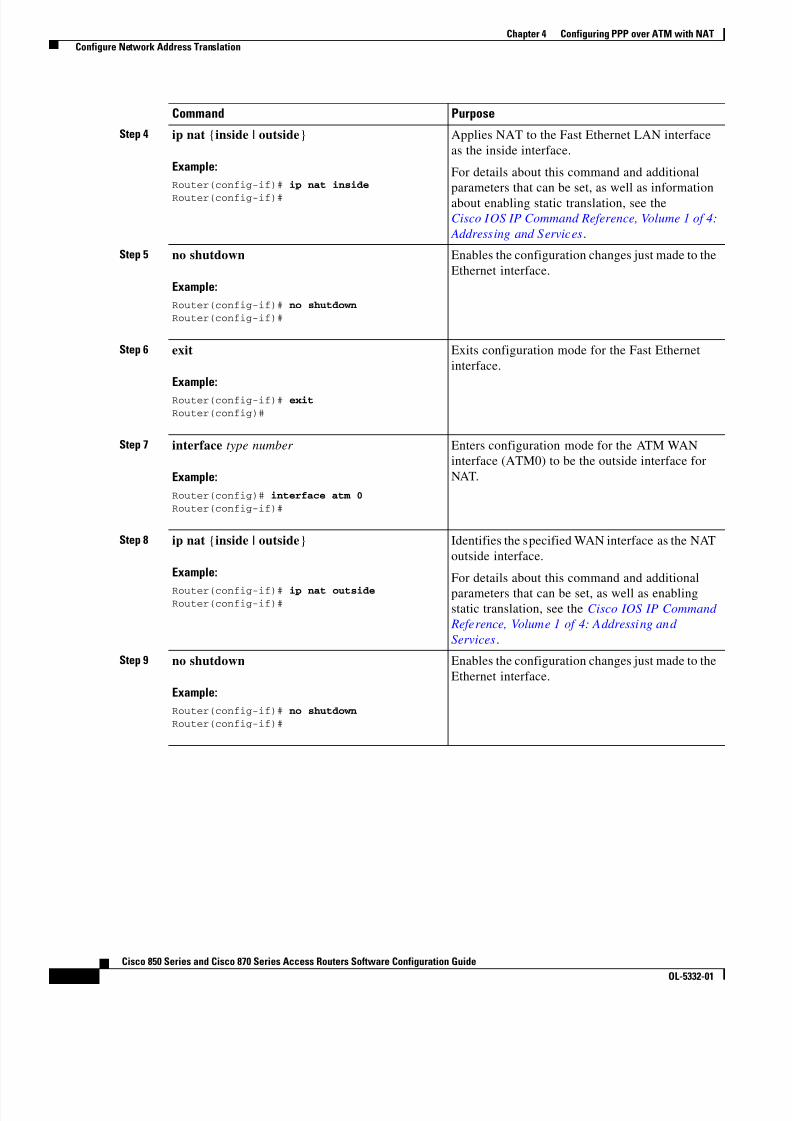
Step 4 ip nat {inside | outside }
Example:Router(config-if)# ip nat inside
Router(config-if)#
Applies NAT to the Fast Ethernet LAN interfaceas the inside interface.
For details about this command and additionalparameters that can be set, as well as informationabout enabling static translation, see theCisco IOS IP Command Reference, Volume 1 of 4:
Addressing and Services .
Step 5 no shutdown
Example:Router(config-if)# no shutdownRouter(config-if)#
Enables the configuration changes just made to theEthernet interface.
Step 6 exit
Example:Router(config-if)# exitRouter(config)#
Exits configuration mode for the Fast Ethernetinterface.
Step 7 interface type number
Example:Router(config)# interface atm 0Router(config-if)#
Enters configuration mode for the ATM WANinterface (ATM0) to be the outside interface forNAT.
Step 8 ip nat {inside | outside }
Example:
Router(config-if)# ip nat outsideRouter(config-if)#
Identifies the specified WAN interface as the NAToutside interface.
For details about this command and additionalparameters that can be set, as well as enablingstatic translation, see the Cisco IOS IP Command
Reference, Volume 1 of 4: Addressing andServices .
Step 9 no shutdown
Example:Router(config-if)# no shutdownRouter(config-if)#
Enables the configuration changes just made to theEthernet interface.
Command Purpose

8/11/2019 Cisco 850 Series and Cisco 870 Series
http://slidepdf.com/reader/full/cisco-850-series-and-cisco-870-series 57/196
8/11/2019 Cisco 850 Series and Cisco 870 Series
http://slidepdf.com/reader/full/cisco-850-series-and-cisco-870-series 58/196

8/11/2019 Cisco 850 Series and Cisco 870 Series
http://slidepdf.com/reader/full/cisco-850-series-and-cisco-870-series 59/196
C H A P T E R
5-1Cisco 850 Series and Cisco 870 Series Access Routers Software Configuration Guide
OL-5332-01
5Configuring a LAN with DHCP and VLANs
The Cisco 870 series routers support clients on both physical LANs and virtual LANs (VLANs). Therouters can use the Dynamic Host Configuration Protocol (DHCP) to enable automatic assignment of IPconfigurations for nodes on these networks.
Figure 5-1 shows a typical deployment scenario with two physical LANs connected by the router and
two VLANs.
Figure 5-1 Physical and Virtual LANs with DHCP Configured on the Cisco Router
9 2 3 3 9
1
2
3
4
1 Fast Ethernet LAN (with multiple networked devices)
2 Router and DHCP server—Cisco 870 series access router—connected to the Internet
3 VLAN 1
4 VLAN 2
DHCP
DHCP, which is described in RFC 2131, uses a client/server model for address allocation. As anadministrator, you can configure your Cisco 800 series router to act as a DHCP server, providing IPaddress assignment and other TCP/IP-oriented configuration information to your workstations. DHCPfrees you from having to manually assign an IP address to each client.

8/11/2019 Cisco 850 Series and Cisco 870 Series
http://slidepdf.com/reader/full/cisco-850-series-and-cisco-870-series 60/196

8/11/2019 Cisco 850 Series and Cisco 870 Series
http://slidepdf.com/reader/full/cisco-850-series-and-cisco-870-series 61/196
8/11/2019 Cisco 850 Series and Cisco 870 Series
http://slidepdf.com/reader/full/cisco-850-series-and-cisco-870-series 62/196

8/11/2019 Cisco 850 Series and Cisco 870 Series
http://slidepdf.com/reader/full/cisco-850-series-and-cisco-870-series 63/196
8/11/2019 Cisco 850 Series and Cisco 870 Series
http://slidepdf.com/reader/full/cisco-850-series-and-cisco-870-series 64/196

8/11/2019 Cisco 850 Series and Cisco 870 Series
http://slidepdf.com/reader/full/cisco-850-series-and-cisco-870-series 65/196
5-7Cisco 850 Series and Cisco 870 Series Access Routers Software Configuration Guide
OL-5332-01
Chapter 5 Configuring a LAN with DHCP and VLANs Configure VLANs
VLAN ISL Id: 3 Name: red-vlan Media Type: Ethernet
VLAN 802.10 Id: 100003 State: Operational MTU: 1500
VLAN ISL Id: 1002 Name: fddi-default Media Type: FDDI VLAN 802.10 Id: 101002 State: Operational MTU: 1500 Bridge Type: SRB Translational Bridged VLAN: 1 Translational Bridged VLAN: 1003
VLAN ISL Id: 1003 Name: token-ring-default Media Type: Token Ring VLAN 802.10 Id: 101003 State: Operational
MTU: 1500 Bridge Type: SRB Ring Number: 0 Bridge Number: 1 Parent VLAN: 1005 Maximum ARE Hop Count: 7 Maximum STE Hop Count: 7 Backup CRF Mode: Disabled Translational Bridged VLAN: 1 Translational Bridged VLAN: 1002
VLAN ISL Id: 1004 Name: fddinet-default Media Type: FDDI Net VLAN 802.10 Id: 101004 State: Operational MTU: 1500 Bridge Type: SRB Bridge Number: 1 STP Type: IBM
VLAN ISL Id: 1005 Name: trnet-default Media Type: Token Ring Net VLAN 802.10 Id: 101005 State: Operational MTU: 1500 Bridge Type: SRB Bridge Number: 1 STP Type: IBM
Router# show vlan-switch
VLAN Name Status Ports---- -------------------------------- --------- -------------------------------1 default active Fa0, Fa1, Fa32 VLAN0002 active Fa21002 fddi-default active1003 token-ring-default active1004 fddinet-default active1005 trnet-default active

8/11/2019 Cisco 850 Series and Cisco 870 Series
http://slidepdf.com/reader/full/cisco-850-series-and-cisco-870-series 66/196
5-8Cisco 850 Series and Cisco 870 Series Access Routers Software Configuration Guide
OL-5332-01
Chapter 5 Configuring a LAN with DHCP and VLANs Configure VLANs
VLAN Type SAID MTU Parent RingNo BridgeNo Stp BrdgMode Trans1 Tr ans2---- ----- ---------- ----- ------ ------ -------- ---- -------- ------ ------1 enet 100001 1500 - - - - - 1002 10032 enet 100002 1500 - - - - - 0 01002 fddi 101002 1500 - - - - - 1 10031003 tr 101003 1500 1005 0 - - srb 1 10021004 fdnet 101004 1500 - - 1 ibm - 0 0
1005 trnet 101005 1500 - - 1 ibm - 0 0
8/11/2019 Cisco 850 Series and Cisco 870 Series
http://slidepdf.com/reader/full/cisco-850-series-and-cisco-870-series 67/196
C H A P T E R
6-1Cisco 850 Series and Cisco 870 Series Access Routers Software Configuration Guide
OL-5332-01
6Configuring a VPN Using Easy VPN and an IPSecTunnel
The Cisco 870 series routers support the creation of Virtual Private Networks (VPNs).
Cisco routers and other broadband devices provide high-performance connections to the Internet, but
many applications also require the security of VPN connections which perform a high level ofauthentication and which encrypt the data between two particular endpoints.
Two types of VPNs are supported—site-to-site and remote access. Site-to-site VPNs are used to connectbranch offices to corporate offices, for example. Remote access VPNs are used by remote clients to login to a corporate network.
The example in this chapter illustrates the configuration of a remote access VPN that uses the Cisco EasyVPN and an IPSec tunnel to configure and secure the connection between the remote client and thecorporate network. Figure 6-1 shows a typical deployment scenario.
Note The material in this chapter does not apply to Cisco 850 series routers. Cisco 850 series routers do notsupport Cisco Easy VPN.
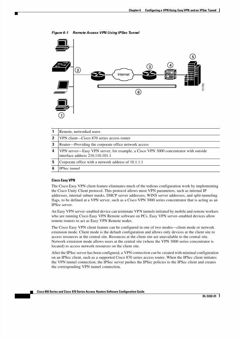
8/11/2019 Cisco 850 Series and Cisco 870 Series
http://slidepdf.com/reader/full/cisco-850-series-and-cisco-870-series 68/196
6-2Cisco 850 Series and Cisco 870 Series Access Routers Software Configuration Guide
OL-5332-01
Chapter 6 Configuring a VPN Using Easy VPN and an IPSec Tunnel
Figure 6-1 Remote Access VPN Using IPSec Tunnel
2
1
1 2 1 7 8 2
Internet
3 4
5
6
1 Remote, networked users
2 VPN client—Cisco 870 series access router
3 Router—Providing the corporate office network access
4 VPN server—Easy VPN server; for example, a Cisco VPN 3000 concentrator with outsideinterface address 210.110.101.1
5 Corporate office with a network address of 10.1.1.1
6 IPSec tunnel
Cisco Easy VPNThe Cisco Easy VPN client feature eliminates much of the tedious configuration work by implementingthe Cisco Unity Client protocol. This protocol allows most VPN parameters, such as internal IPaddresses, internal subnet masks, DHCP server addresses, WINS server addresses, and split-tunnelingflags, to be defined at a VPN server, such as a Cisco VPN 3000 series concentrator that is acting as anIPSec server.
An Easy VPN server–enabled device can terminate VPN tunnels initiated by mobile and remote workerswho are running Cisco Easy VPN Remote software on PCs. Easy VPN server–enabled devices allowremote routers to act as Easy VPN Remote nodes.
The Cisco Easy VPN client feature can be configured in one of two modes—client mode or networkextension mode. Client mode is the default configuration and allows only devices at the client site to
access resources at the central site. Resources at the client site are unavailable to the central site.Network extension mode allows users at the central site (where the VPN 3000 series concentrator islocated) to access network resources on the client site.
After the IPSec server has been configured, a VPN connection can be created with minimal configurationon an IPSec client, such as a supported Cisco 870 series access router. When the IPSec client initiatesthe VPN tunnel connection, the IPSec server pushes the IPSec policies to the IPSec client and createsthe corresponding VPN tunnel connection.

8/11/2019 Cisco 850 Series and Cisco 870 Series
http://slidepdf.com/reader/full/cisco-850-series-and-cisco-870-series 69/196

8/11/2019 Cisco 850 Series and Cisco 870 Series
http://slidepdf.com/reader/full/cisco-850-series-and-cisco-870-series 70/196

8/11/2019 Cisco 850 Series and Cisco 870 Series
http://slidepdf.com/reader/full/cisco-850-series-and-cisco-870-series 71/196
6-5Cisco 850 Series and Cisco 870 Series Access Routers Software Configuration Guide
OL-5332-01
Chapter 6 Configuring a VPN Using Easy VPN and an IPSec Tunnel Configure Group Policy Information
Configure Group Policy InformationPerform these steps to configure the group policy, beginning in global configuration mode:
Command or Action PurposeStep 1 crypto isakmp client configuration group
{group-name | default }
Example:Router(config)# crypto isakmp clientconfiguration group rtr-remoteRouter(config-isakmp-group)#
Creates an IKE policy group containing attributesto be downloaded to the remote client.
Also enters the Internet Security Association Keyand Management Protocol (ISAKMP) grouppolicy configuration mode.
Step 2 key name
Example:Router(config-isakmp-group)# keysecret-passwordRouter(config-isakmp-group)#
Specifies the IKE pre-shared key for the grouppolicy.
Step 3 dns primary-server
Example:Router(config-isakmp-group)# dns 10.50.10.1Router(config-isakmp-group)#
Specifies the primary Domain Name System(DNS) server for the group.
Note You may also want to specify WindowsInternet Naming Service (WINS) serversfor the group by using the wins command.
Step 4 domain name
Example:Router(config-isakmp-group)# domaincompany.com Router(config-isakmp-group)#
Specifies group domain membership.
Step 5 exit
Example:Router(config-isakmp-group)# exitRouter(config)#
Exits IKE group policy configuration mode, andenters global configuration mode.
Step 6 ip local pool {default | poolname }
[low-ip-address
[high-ip-address
]]
Example:Router(config)# ip local pool dynpool30.30.30.20 30.30.30.30Router(config)#
Specifies a local address pool for the group.
For details about this command and additionalparameters that can be set, see the Cisco IOS DialTechnologies Command Reference .

8/11/2019 Cisco 850 Series and Cisco 870 Series
http://slidepdf.com/reader/full/cisco-850-series-and-cisco-870-series 72/196
6-6Cisco 850 Series and Cisco 870 Series Access Routers Software Configuration Guide
OL-5332-01
Chapter 6 Configuring a VPN Using Easy VPN and an IPSec Tunnel Apply Mode Configuration to the Crypto Map
Apply Mode Configuration to the Crypto MapPerform these steps to apply mode configuration to the crypto map, beginning in global configurationmode:
Command or Action Purpose
Step 1 crypto map map-name isakmp authorization listlist-name
Example:Router(config)# crypto map dynmap isakmpauthorization list rtr-remoteRouter(config)#
Applies mode configuration to the crypto map andenables key lookup (IKE queries) for the grouppolicy from an authentication, authorization, andaccounting (AAA) server.
Step 2 crypto map tag client configuration address[initiate | respond ]
Example:Router(config)# crypto map dynmap clientconfiguration address respondRouter(config)#
Configures the router to reply to modeconfiguration requests from remote clients.
Enable Policy LookupPerform these steps to enable policy lookup through AAA, beginning in global configuration mode:
Command or Action PurposeStep 1 aaa new-model
Example:Router(config)# aaa new-modelRouter(config)#
Enables the AAA access control model.
Step 2 aaa authentication login {default | list-name } method1 [method2... ]
Example:Router(config)# aaa authentication loginrtr-remote localRouter(config)#
Specifies AAA authentication of selected users atlogin, and specifies the method used.
This example uses a local authentication database.You could also use a RADIUS server for this. Fordetails, see the Cisco IOS Security Configuration
Guide and Cisco IOS Security Command Reference .

8/11/2019 Cisco 850 Series and Cisco 870 Series
http://slidepdf.com/reader/full/cisco-850-series-and-cisco-870-series 73/196

8/11/2019 Cisco 850 Series and Cisco 870 Series
http://slidepdf.com/reader/full/cisco-850-series-and-cisco-870-series 74/196

8/11/2019 Cisco 850 Series and Cisco 870 Series
http://slidepdf.com/reader/full/cisco-850-series-and-cisco-870-series 75/196

8/11/2019 Cisco 850 Series and Cisco 870 Series
http://slidepdf.com/reader/full/cisco-850-series-and-cisco-870-series 76/196
6-10Cisco 850 Series and Cisco 870 Series Access Routers Software Configuration Guide
OL-5332-01
Chapter 6 Configuring a VPN Using Easy VPN and an IPSec Tunnel Create an Easy VPN Remote Configuration
Create an Easy VPN Remote ConfigurationThe router acting as the IPSec remote router must create an Easy VPN remote configuration and assignit to the outgoing interface.
Perform these steps to create the remote configuration, beginning in global configuration mode:
Step 2 crypto map map-name
Example:Router(config-if)# crypto map static-map
Router(config-if)#
Applies the crypto map to the interface.
See the Cisco IOS Security Command Reference for more detail about this command.
Step 3 exit
Example:Router(config-crypto-map)# exitRouter(config)#
Returns to global configuration mode.
Command or Action Purpose
Command or Action Purpose
Step 1 crypto ipsec client ezvpn name
Example:Router(config)# crypto ipsec client ezvpnezvpnclientRouter(config-crypto-ezvpn)#
Creates a Cisco Easy VPN remote configuration,and enters Cisco Easy VPN remote configurationmode.
Step 2 group group-name key group-key
Example:Router(config-crypto-ezvpn)# groupezvpnclient key secret-passwordRouter(config-crypto-ezvpn)#
Specifies the IPSec group and IPSec key value forthe VPN connection.
Step 3 peer { ipaddress | hostname }
Example:Router(config-crypto-ezvpn)# peer192.168.100.1
Router(config-crypto-ezvpn)#
Specifies the peer IP address or hostname for theVPN connection.
Note A hostname can be specified only whenthe router has a DNS server available forhostname resolution.
Step 4 mode {client | network-extension | networkextension plus }
Example:Router(config-crypto-ezvpn)# mode clientRouter(config-crypto-ezvpn)#
Specifies the VPN mode of operation.

8/11/2019 Cisco 850 Series and Cisco 870 Series
http://slidepdf.com/reader/full/cisco-850-series-and-cisco-870-series 77/196
6-11Cisco 850 Series and Cisco 870 Series Access Routers Software Configuration Guide
OL-5332-01
Chapter 6 Configuring a VPN Using Easy VPN and an IPSec Tunnel Verifying Your Easy VPN Configuration
Verifying Your Easy VPN ConfigurationRouter# show crypto ipsec client ezvpn
Tunnel name :ezvpnclientInside interface list:vlan 1Outside interface:fastethernet 4Current State:IPSEC_ACTIVELast Event:SOCKET_UPAddress:8.0.0.5Mask:255.255.255.255Default Domain:cisco.com
Configuration ExampleThe following configuration example shows a portion of the configuration file for the VPN and IPSectunnel described in this chapter.
!aaa new-model!aaa authentication login rtr-remote localaaa authorization network rtr-remote localaaa session-id common
Step 5 exit
Example:Router(config-crypto-ezvpn)# exit
Router(config)#
Returns to global configuration mode.
Step 6 interface type number
Example:Router(config)# interface fastethernet 4Router(config-if)#
Enters the interface configuration mode for theinterface to which you want the Cisco Easy VPNremote configuration applied.
Note For routers with an ATM WAN interface,this command would be interface atm 0 .
Step 7 crypto ipsec client ezvpn name [outside | inside ]
Example:Router(config-if)# crypto ipsec clientezvpn ezvpnclient outsideRouter(config-if)#
Assigns the Cisco Easy VPN remote configurationto the WAN interface, causing the router toautomatically create the NAT or port addresstranslation (PAT) and access list configuration
needed for the VPN connection.
Step 8 exit
Example:Router(config-crypto-ezvpn)# exitRouter(config)#
Returns to global configuration mode.
Command or Action Purpose
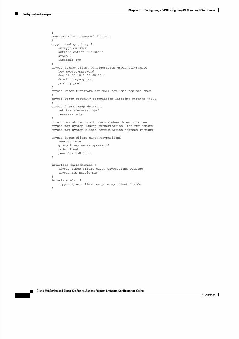
8/11/2019 Cisco 850 Series and Cisco 870 Series
http://slidepdf.com/reader/full/cisco-850-series-and-cisco-870-series 78/196

8/11/2019 Cisco 850 Series and Cisco 870 Series
http://slidepdf.com/reader/full/cisco-850-series-and-cisco-870-series 79/196

8/11/2019 Cisco 850 Series and Cisco 870 Series
http://slidepdf.com/reader/full/cisco-850-series-and-cisco-870-series 80/196
7-2Cisco 850 Series and Cisco 870 Series Access Routers Software Configuration Guide
OL-5332-01
Chapter 7 Configuring VPNs Using an IPSec Tunnel and Generic Routing Encapsulation Configure a VPN
GRE Tunnels
GRE tunnels are typically used to establish a VPN between the Cisco router and a remote device thatcontrols access to a private network, such as a corporate network. Traffic forwarded through the GREtunnel is encapsulated and routed ou t onto the physical interface of the router. When a GRE interface isused, the Cisco router and the router that controls access to the corporate network can support dynamicIP routing protocols to exchange routing updates over the tunnel, and to enable IP multicast traffic.Supported IP routing protocols include Enhanced Interior Gateway Routing Protocol (EIGRP), RoutingInformation Protocol (RIP), Intermediate System-to-Intermediate System (IS-IS), Open Shortest PathFirst (OSPF), and Border Gateway Protocol (BGP).
Note When IP Security (IPSec) is used with GRE, the access list for encrypting traffic does not list the desiredend network and applications, but instead refers to the permitted source and destination of the GREtunnel in the outbound direction. All packets forwarded to the GRE tunnel are encrypted if no furtheraccess control lists (ACLs) are applied to the tunnel interface.
VPNs
VPN configuration information must be configured on both endpoints; for example, on your Cisco rou terand at the remote user, or on your Cisco router and on another router. You must specify parameters, suchas internal IP addresses, internal subnet masks, DHCP server addresses, and Network AddressTranslation (NAT).
Configuration Tasks
Perform the following tasks to configure this network scenario:
• Configure a VPN
• Configure a GRE Tunnel
A configuration example showing the results of these configuration tasks is provided in the“Configuration Example” section on page 7-9 .
Note The procedures in this chapter assume that you have already configured basic router features as well asPPPoE or PPPoA with NAT, DCHP, and VLANs. If you have not performed these configurations tasks,see Chapter 1, “Basic Router Configuration,” Chapter 3, “Configuring PPP over Ethernet with NAT,” Chapter 4, “Configuring PPP over ATM with NAT,” and Chapter 5, “Configuring a LAN with DHCPand VLANs,” as appropriate for your router.
Configure a VPNPerform the following tasks to configure a VPN over an IPSec tunnel:
• Configure the IKE Policy • Configure Group Policy Information
• Enable Policy Lookup
• Configure IPSec Transforms and Protocols
• Configure the IPSec Crypto Method and Parameters
• Apply the Crypto Map to the Physical Interface
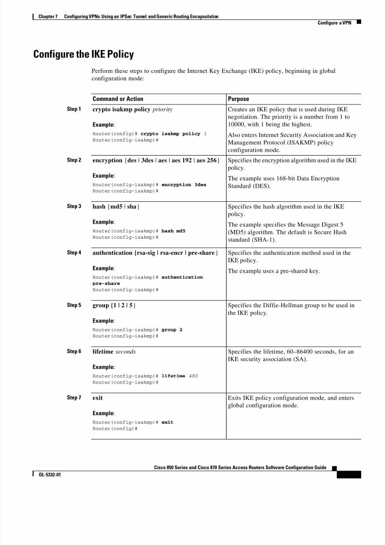
8/11/2019 Cisco 850 Series and Cisco 870 Series
http://slidepdf.com/reader/full/cisco-850-series-and-cisco-870-series 81/196
7-3Cisco 850 Series and Cisco 870 Series Access Routers Software Configuration Guide
OL-5332-01
Chapter 7 Configuring VPNs Using an IPSec Tunnel and Generic Routing Encapsulation Configure a VPN
Configure the IKE PolicyPerform these steps to configure the Internet Key Exchange (IKE) policy, beginning in globalconfiguration mode:
Command or Action Purpose
Step 1 crypto isakmp policy priority
Example:Router(config)# crypto isakmp policy 1Router(config-isakmp)#
Creates an IKE policy that is used during IKEnegotiation. The priority is a number from 1 to10000, with 1 being the highest.
Also enters Internet Security Association and KeyManagement Protocol (ISAKMP) policyconfiguration mode.
Step 2 encryption {des | 3des | aes | aes 192 | aes 256 }
Example:Router(config-isakmp)# encryption 3des
Router(config-isakmp)#
Specifies the encryption algorithm used in the IKEpolicy.
The example uses 168-bit Data EncryptionStandard (DES).
Step 3 hash {md5 | sha }
Example:Router(config-isakmp)# hash md5Router(config-isakmp)#
Specifies the hash algorithm used in the IKEpolicy.
The example specifies the Message Digest 5(MD5) algorithm. The default is Secure Hashstandard (SHA-1).
Step 4 authentication {rsa-sig | rsa-encr | pre-share }
Example:Router(config-isakmp)# authentication
pre-shareRouter(config-isakmp)#
Specifies the authentication method used in theIKE policy.
The example uses a pre-shared key.
Step 5 group {1 | 2 | 5 }
Example:Router(config-isakmp)# group 2Router(config-isakmp)#
Specifies the Diffie-Hellman group to be used inthe IKE policy.
Step 6 lifetime seconds
Example:Router(config-isakmp)# lifetime 480
Router(config-isakmp)#
Specifies the lifetime, 60–86400 seconds, for anIKE security association (SA).
Step 7 exit
Example:Router(config-isakmp)# exitRouter(config)#
Exits IKE policy configuration mode, and entersglobal configuration mode.

8/11/2019 Cisco 850 Series and Cisco 870 Series
http://slidepdf.com/reader/full/cisco-850-series-and-cisco-870-series 82/196
7-4Cisco 850 Series and Cisco 870 Series Access Routers Software Configuration Guide
OL-5332-01
Chapter 7 Configuring VPNs Using an IPSec Tunnel and Generic Routing Encapsulation Configure a VPN
Configure Group Policy InformationPerform these steps to configure the group policy, beginning in global configuration mode:
Command or Action Purpose
Step 1 crypto isakmp client configuration group{group-name | default}
Example:Router(config)# crypto isakmp clientconfiguration group rtr-remoteRouter(config-isakmp-group)#
Creates an IKE policy group that containsattributes to be downloaded to the remote client.
Also enters Internet Security Association KeyManagement Protocol (ISAKMP) policyconfiguration mode.
Step 2 key name
Example:Router(config-isakmp-group)# keysecret-passwordRouter(config-isakmp-group)#
Specifies the IKE pre-shared key for the grouppolicy.
Step 3 dns primary-server
Example:Router(config-isakmp-group)# dns 10.50.10.1Router(config-isakmp-group)#
Specifies the primary Domain Name Service(DNS) server for the group.
Note You may also want to spec ify WindowsInternet Naming Service (WINS) serversfor the group by using the wins command.
Step 4 domain name
Example:Router(config-isakmp-group)# domaincompany.com Router(config-isakmp-group)#
Specifies group domain membership.
Step 5 exit
Example:Router(config-isakmp-group)# exitRouter(config)#
Exits IKE group policy configuration mode, andenters global configuration mode.
Step 6 ip local pool {default | poolname }[low-ip-address [high-ip-address ]]
Example:Router(config)# ip local pool dynpool30.30.30.20 30.30.30.30Router(config)#
Specifies a local address pool for the group.
For details about this command and additionalparameters that can be set, see the Cisco IOS DialTechnologies Command Reference .
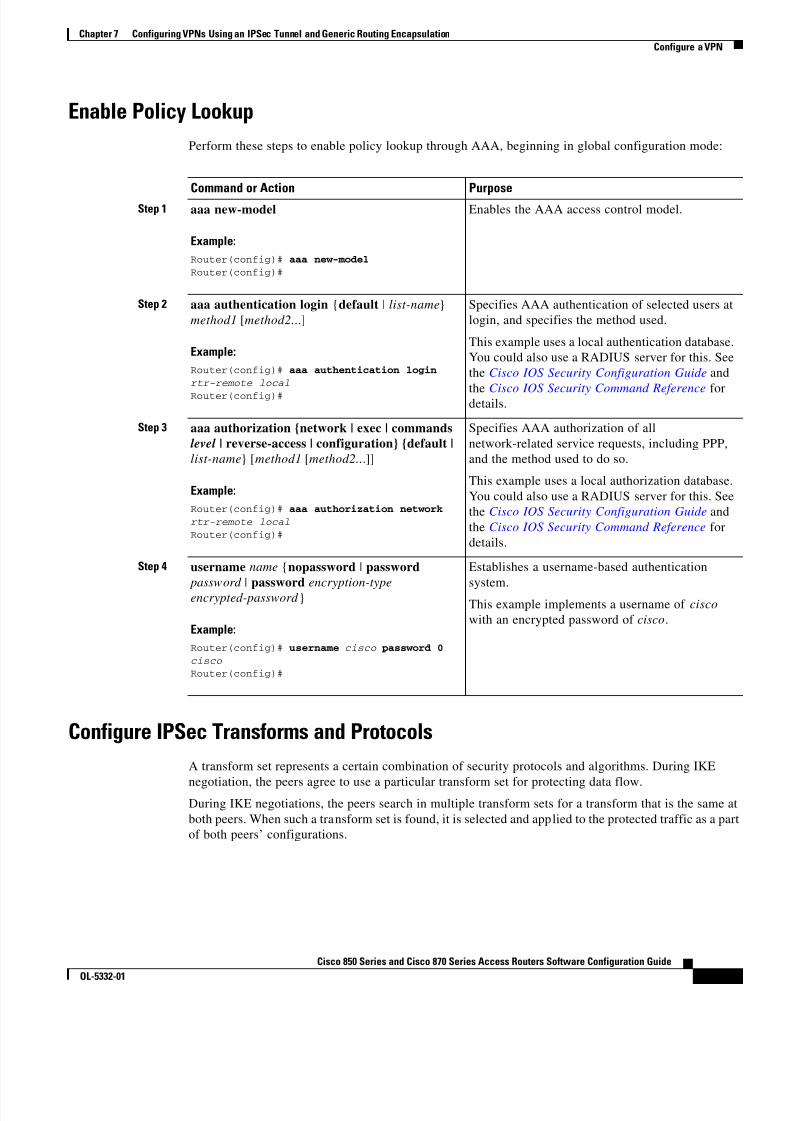
8/11/2019 Cisco 850 Series and Cisco 870 Series
http://slidepdf.com/reader/full/cisco-850-series-and-cisco-870-series 83/196
7-5Cisco 850 Series and Cisco 870 Series Access Routers Software Configuration Guide
OL-5332-01
Chapter 7 Configuring VPNs Using an IPSec Tunnel and Generic Routing Encapsulation Configure a VPN
Enable Policy LookupPerform these steps to enable policy lookup through AAA, beginning in global configuration mode:
Command or Action Purpose
Step 1 aaa new-model
Example:Router(config)# aaa new-modelRouter(config)#
Enables the AAA access control model.
Step 2 aaa authentication login {default | list-name } method1 [method2... ]
Example:Router(config)# aaa authentication loginrtr-remote local
Router(config)#
Specifies AAA authentication of selected users atlogin, and specifies the method used.
This example uses a local authentication database.You could also use a RADIUS server for this. Seethe Cisco IOS Security Configuration Guide and
the Cisco IOS Security Command Reference fordetails.
Step 3 aaa authorization {network | exec | commandslevel | reverse-access | configuration} {default |list-name } [ method1 [method2... ]]
Example:Router(config)# aaa authorization networkrtr-remote localRouter(config)#
Specifies AAA authorization of allnetwork-related service requests, including PPP,and the method used to do so.
This example uses a local authorization database.You could also use a RADIUS server for this. Seethe Cisco IOS Security Configuration Guide andthe Cisco IOS Security Command Reference fordetails.
Step 4 username name {nopassword | password password | password encryption-type encrypted-password }
Example:Router(config)# username cisco password 0cisco Router(config)#
Establishes a username-based authenticationsystem.
This example implements a username of cisco with an encrypted password of cisco .
Configure IPSec Transforms and ProtocolsA transform set represents a certain combination of security protocols and algorithms. During IKE
negotiation, the peers agree to use a particular transform set for protecting data flow.During IKE negotiations, the peers search in multiple transform sets for a transform that is the same atboth peers. When such a transform set is found, it is selected and applied to the protected traffic as a partof both peers’ configurations.
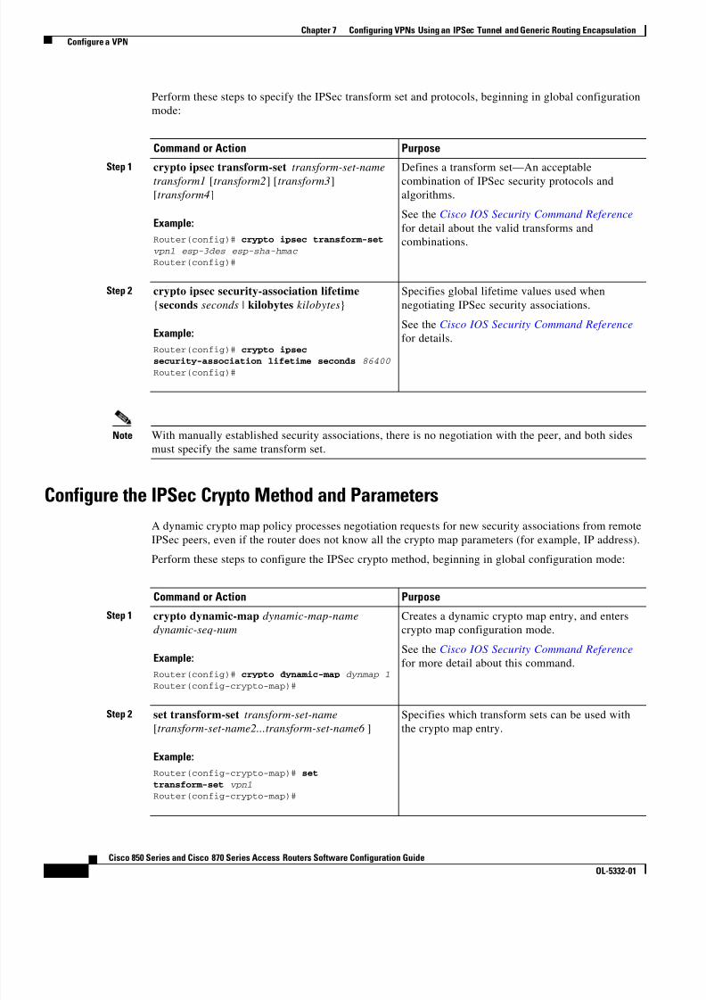
8/11/2019 Cisco 850 Series and Cisco 870 Series
http://slidepdf.com/reader/full/cisco-850-series-and-cisco-870-series 84/196
7-6Cisco 850 Series and Cisco 870 Series Access Routers Software Configuration Guide
OL-5332-01
Chapter 7 Configuring VPNs Using an IPSec Tunnel and Generic Routing Encapsulation Configure a VPN
Perform these steps to specify the IPSec transform set and protocols, beginning in global configurationmode:
Command or Action Purpose
Step 1 crypto ipsec transform-set transform-set-nametransform1 [ transform2 ] [ transform3 ][transform4 ]
Example:Router(config)# crypto ipsec transform-setvpn1 esp-3des esp-sha-hmac Router(config)#
Defines a transform set—An acceptablecombination of IPSec security protocols andalgorithms.
See the Cisco IOS Security Command Reference for detail about the valid transforms andcombinations.
Step 2 crypto ipsec security-association lifetime{seconds seconds | kilobytes kilobytes }
Example:
Router(config)# crypto ipsecsecurity-association lifetime seconds 86400Router(config)#
Specifies global lifetime values used whennegotiating IPSec security associations.
See the Cisco IOS Security Command Reference for details.
Note With manually established security associations, there is no negotiation with the peer, and both sidesmust specify the same transform set.
Configure the IPSec Crypto Method and Parameters
A dynamic crypto map policy processes negotiation requests for new security associations from remoteIPSec peers, even if the router does not know all the crypto map parameters (for example, IP address).
Perform these steps to configure the IPSec crypto method, beginning in global configuration mode:
Command or Action Purpose
Step 1 crypto dynamic-map dynamic-map-namedynamic-seq-num
Example:Router(config)# crypto dynamic-map dynmap 1Router(config-crypto-map)#
Creates a dynamic crypto map entry, and enterscrypto map configuration mode.
See the Cisco IOS Security Command Reference for more detail about this command.
Step 2 set transform-set transform-set-name[transform-set-name2...transform-set-name6 ]
Example:Router(config-crypto-map)# settransform-set vpn1Router(config-crypto-map)#
Specifies which transform sets can be used withthe crypto map entry.

8/11/2019 Cisco 850 Series and Cisco 870 Series
http://slidepdf.com/reader/full/cisco-850-series-and-cisco-870-series 85/196
7-7Cisco 850 Series and Cisco 870 Series Access Routers Software Configuration Guide
OL-5332-01
Chapter 7 Configuring VPNs Using an IPSec Tunnel and Generic Routing Encapsulation Configure a VPN
Apply the Crypto Map to the Physical InterfaceThe crypto maps must be applied to each interface through which IPSec traffic flows. Applying thecrypto map to the physical interface instructs the router to evaluate all the traffic against the securityassociations database. With the default configurations, the router provides secure connectivity byencrypting the traffic sent between remote sites. However, the public interface still allows the rest of the
traffic to pass and provides connectivity to the Internet.Perform these steps to apply a crypto map to an interface, beginning in global configuration mode:
Step 3 reverse-route
Example:Router(config-crypto-map)# reverse-route
Router(config-crypto-map)#
Creates source proxy information for the cryptomap entry.
See the Cisco IOS Security Command Reference for details.
Step 4 exit
Example:Router(config-crypto-map)# exitRouter(config)#
Enters global configuration mode.
Step 5 crypto map map-name seq-num [ ipsec-isakmp ][dynamic dynamic-map-name ] [ discover ][profile profile-name ]
Example:Router(config)# crypto map static-map 1ipsec-isakmp dynamic dynmapRouter(config)#
Creates a crypto map profile.
Command or Action Purpose
Command or Action Purpose
Step 1 interface type number
Example:Router(config)# interface fastethernet 4Router(config-if)#
Enters interface configuration mode for theinterface to which you want to apply the cryptomap.

8/11/2019 Cisco 850 Series and Cisco 870 Series
http://slidepdf.com/reader/full/cisco-850-series-and-cisco-870-series 86/196
7-8Cisco 850 Series and Cisco 870 Series Access Routers Software Configuration Guide
OL-5332-01
Chapter 7 Configuring VPNs Using an IPSec Tunnel and Generic Routing Encapsulation Configure a GRE Tunnel
Configure a GRE TunnelPerform these steps to configure a GRE tunnel, beginning in global configuration mode:
Step 2 crypto map map-name
Example:Router(config-if)# crypto map static-map
Router(config-if)#
Applies the crypto map to the interface.
See the Cisco IOS Security Command Reference for more detail about this command.
Step 3 exit
Example:Router(config-if)# exitRouter(config)#
Enters global configuration mode.
Command or Action Purpose
Command or Action Purpose
Step 1 interface type number
Example:Router(config)# interface tunnel 1Router(config-if)#
Creates a tunnel interface and enters interfaceconfiguration mode.
Step 2 ip address subnet mask
Example:Router(config-if)# ip address 10.62.1.193 255.255.255.255Router(config-if)#
Assigns an address to the tunnel.
Step 3 tunnel source interface-type number
Example:Router(config-if)# tunnel sourcefastethernet 0Router(config-if)#
Specifies the source endpoint of the router for theGRE tunnel.
Step 4 tunnel destination default-gateway-ip-address
Example:Router(config-if)# tunnel destination192.168.101.1Router(config-if)#
Specifies the destination endpoint of the router for
the GRE tunnel.

8/11/2019 Cisco 850 Series and Cisco 870 Series
http://slidepdf.com/reader/full/cisco-850-series-and-cisco-870-series 87/196
7-9Cisco 850 Series and Cisco 870 Series Access Routers Software Configuration Guide
OL-5332-01
Chapter 7 Configuring VPNs Using an IPSec Tunnel and Generic Routing Encapsulation Configuration Example
Configuration ExampleThe following configuration example shows a portion of the configuration file for a VPN using a GREtunnel scenario described in the preceding sections.
!aaa new-model!aaa authentication login rtr-remote localaaa authorization network rtr-remote localaaa session-id common!username cisco password 0 cisco!interface tunnel 1
ip address 10.62.1.193 255.255.255.252
Step 5 crypto map map-name
Example:Router(config-if)# crypto map static-map
Router(config-if)#
Assigns a crypto map to the tunnel.
Note Dynamic routing or static routes to thetunnel interface must be configured toestablish connectivity between the sites.See the Cisco IOS Security ConfigurationGuide for details.
Step 6 exit
Example:Router(config-if)# exitRouter(config)#
Exits interface configuration mode, and returns toglobal configuration mode.
Step 7 ip access-list {standard | extended} access-list-name
Example:Router(config)# ip access-list extendedvpnstatic1Router(config-acl)#
Enters ACL configuration mode for the namedACL that is used by the crypto map.
Step 8 permit protocol source source-wildcarddestination destination-wildcard
Example:Router(config-acl)# permit gre host192.168.100.1 host 192.168.101.1Router(config-acl)#
Specifies that only GRE traffic is permitted on theoutbound interface.
Step 9 exit
Example:Router(config-acl)# exitRouter(config)#
Returns to global configuration mode.
Command or Action Purpose
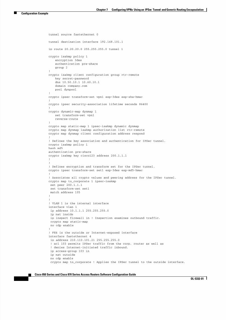
8/11/2019 Cisco 850 Series and Cisco 870 Series
http://slidepdf.com/reader/full/cisco-850-series-and-cisco-870-series 88/196
7-10Cisco 850 Series and Cisco 870 Series Access Routers Software Configuration Guide
OL-5332-01
Chapter 7 Configuring VPNs Using an IPSec Tunnel and Generic Routing Encapsulation Configuration Example
tunnel source fastethernet 0
tunnel destination interface 192.168.101.1
ip route 20.20.20.0 255.255.255.0 tunnel 1
crypto isakmp policy 1encryption 3desauthentication pre-sharegroup 2
!crypto isakmp client configuration group rtr-remote
key secret-passworddns 10.50.10.1 10.60.10.1domain company.com pool dynpool
!crypto ipsec transform-set vpn1 esp-3des esp-sha-hmac!crypto ipsec security-association lifetime seconds 86400!
crypto dynamic-map dynmap 1set transform-set vpn1reverse-route
!crypto map static-map 1 ipsec-isakmp dynamic dynmapcrypto map dynmap isakmp authorization list rtr-remotecrypto map dynmap client configuration address respond!! Defines the key association and authentication for IPSec tunnel.crypto isakmp policy 1hash md5authentication pre-sharecrypto isakmp key cisco123 address 200.1.1.1!!! Defines encryption and transform set for the IPSec tunnel.crypto ipsec transform-set set1 esp-3des esp-md5-hmac!! Associates all crypto values and peering address for the IPSec tunnel.crypto map to_corporate 1 ipsec-isakmp
set peer 200.1.1.1 set transform-set set1 match address 105!!! VLAN 1 is the internal interfaceinterface vlan 1 ip address 10.1.1.1 255.255.255.0 ip nat inside ip inspect firewall in ! Inspection examines outbound traffic.
crypto map static-mapno cdp enable
!! FE4 is the outside or Internet-exposed interfaceinterface fastethernet 4 ip address 210.110.101.21 255.255.255.0 ! acl 103 permits IPSec traffic from the corp. router as well as
! denies Internet-initiated traffic inbound.ip access-group 103 inip nat outside
no cdp enable crypto map to_corporate ! Applies the IPSec tunnel to the outside interface.

8/11/2019 Cisco 850 Series and Cisco 870 Series
http://slidepdf.com/reader/full/cisco-850-series-and-cisco-870-series 89/196
7-11Cisco 850 Series and Cisco 870 Series Access Routers Software Configuration Guide
OL-5332-01
Chapter 7 Configuring VPNs Using an IPSec Tunnel and Generic Routing Encapsulation Configuration Example
!! Utilize NAT overload in order to make best use of the! single address provided by the ISP.ip nat inside source list 102 interface Ethernet1 overloadip classlessip route 0.0.0.0 0.0.0.0 210.110.101.1no ip http server
!!! acl 102 associated addresses used for NAT.access-list 102 permit ip 10.1.1.0 0.0.0.255 any! acl 103 defines traffic allowed from the peer for the IPSec tunnel.access-list 103 permit udp host 200.1.1.1 any eq isakmpaccess-list 103 permit udp host 200.1.1.1 eq isakmp anyaccess-list 103 permit esp host 200.1.1.1 any! Allow ICMP for debugging but should be disabled because of security implications.access-list 103 permit icmp any anyaccess-list 103 deny ip any any ! Prevents Internet-initiated traffic inbound.! acl 105 matches addresses for the IPSec tunnel to or from the corporate network.access-list 105 permit ip 10.1.1.0 0.0.0.255 192.168.0.0 0.0.255.255no cdp run

8/11/2019 Cisco 850 Series and Cisco 870 Series
http://slidepdf.com/reader/full/cisco-850-series-and-cisco-870-series 90/196
7-12Cisco 850 Series and Cisco 870 Series Access Routers Software Configuration Guide
OL-5332-01
Chapter 7 Configuring VPNs Using an IPSec Tunnel and Generic Routing Encapsulation Configuration Example
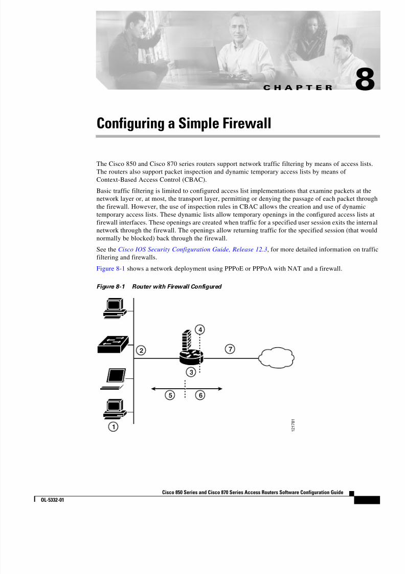
8/11/2019 Cisco 850 Series and Cisco 870 Series
http://slidepdf.com/reader/full/cisco-850-series-and-cisco-870-series 91/196
C H A P T E R
8-1Cisco 850 Series and Cisco 870 Series Access Routers Software Configuration Guide
OL-5332-01
8Configuring a Simple Firewall
The Cisco 850 and Cisco 870 series routers support network traffic filtering by means of access lists.The routers also support packet inspection and dynamic temporary access lists by means ofContext-Based Access Control (CBAC).
Basic traffic filtering is limited to configured access list implementations that examine packets at the
network layer or, at most, the transport layer, permitting or denying the passage of each packet throughthe firewall. However, the use of inspection rules in CBAC allows the creation and use of dynamictemporary access lists. These dynamic lists allow temporary openings in the configured access lists atfirewall interfaces. These openings are created when traffic for a specified user session exits the internalnetwork through the firewall. The openings allow returning traffic for the specified session (that wouldnormally be blocked) back through the firewall.
See the Cisco IOS Security Configuration Guide, Release 12.3 , for more detailed information on trafficfiltering and firewalls.
Figure 8-1 shows a network deployment using PPPoE or PPPoA with NAT and a firewall.
Figure 8-1 Router with Firewall Configured
1 2 1 7 8 1
2
3
7
5 6
1
4
8/11/2019 Cisco 850 Series and Cisco 870 Series
http://slidepdf.com/reader/full/cisco-850-series-and-cisco-870-series 92/196
1 Multiple networked devices—Desktops, laptop PCs, switches
2 Fast Ethernet LAN interface (the inside interface for NAT)
3 PPPoE or PPPoA client and firewall implementation—Cisco 851/871 or Cisco 857/876/877/878series access router, respectively
4 Point at which NAT occurs
5 Protected network
6 Unprotected network
7 Fast Ethernet or ATM WAN interface (the outside interface for NAT)
8-2Cisco 850 Series and Cisco 870 Series Access Routers Software Configuration Guide
OL-5332-01
Chapter 8 Configuring a Simple Firewall
In the configuration example that follows, the firewall is applied to the outside WAN interface (FE4) onthe Cisco 851 or Cisco 871 and protects the Fast Ethernet LAN on FE0 by filtering and inspecting alltraffic entering the router on the Fast Ethernet WAN interface FE4. Note that in this example, the networktraffic originating from the corporate network, network address 10.1.1.0, is considered safe traffic andis not filtered.
Configuration Tasks
Perform the following tasks to configure this network scenario:
• Configure Access Lists
• Configure Inspection Rules
• Apply Access Lists and Inspection Rules to Interfaces
A configuration example that shows the results of these configuration tasks is provided in the“Configuration Example” section on page 8-5 .
Note The procedures in this chapter assume that you have already configured basic router features as well as
PPPoE or PPPoA with NAT. If you have not performed these configurations tasks, see Chapter 1, “BasicRouter Configuration,” Chapter 3, “Configuring PPP over Ethernet with NAT,” and Chapter 4,“Configuring PPP over ATM with NAT,” as appropriate for your router. You may have also configuredDHCP, VLANs, and secure tunnels.

8/11/2019 Cisco 850 Series and Cisco 870 Series
http://slidepdf.com/reader/full/cisco-850-series-and-cisco-870-series 93/196
8-3Cisco 850 Series and Cisco 870 Series Access Routers Software Configuration Guide
OL-5332-01
Chapter 8 Configuring a Simple Firewall Configure Access Lists
Configure Access ListsPerform these steps to create access lists for use by the firewall, beginning in global configuration mode:
Command PurposeStep 1 access-list access-list-number {deny | permit }
protocol source source-wildcard [operator [ port ]]destination
Example:Router(config)# access-list 103 deny ip anyanyRouter(config)# access-list 103 permit host200.1.1.1 eq isakmp anyRouter(config)#
Creates an access list which prevents Internet-initiated traffic from reaching the local (inside)network of the router, and which comparessource and destination ports.
See the Cisco IOS IP Command Reference,Volume 1 of 4: Addressing and Services fordetails about this command.
Configure Inspection RulesPerform these steps to configure firewall inspection rules for all TCP and UDP traffic, as well as specificapplication protocols as defined by the security policy, beginning in global configuration mode:
Command or Action Purpose
Step 1 ip inspect name inspection-name protocol
Example:Router(config)# ip inspect name firewall tcp
Router(config)#
Defines an inspection rule for a particularprotocol.
Step 2 ip inspect name inspection-name protocol
Example:Router(config)# ip inspect name firewall rtspRouter(config)# ip inspect name firewall h323Router(config)# ip inspect name firewallnetshow Router(config)# ip inspect name firewall ftpRouter(config)# ip inspect name firewallsqlnetRouter(config)#
Repeat this command for each inspection rulethat you wish to use.
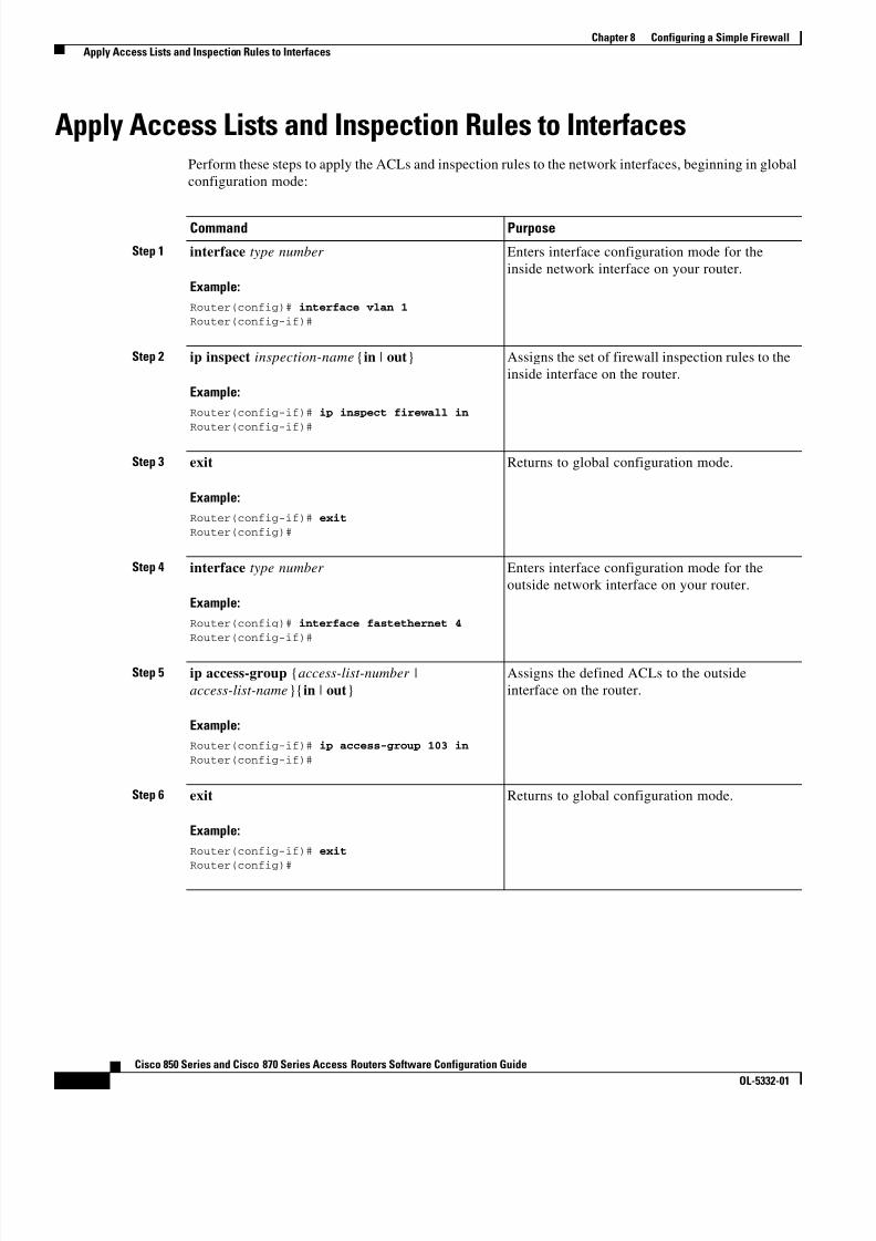
8/11/2019 Cisco 850 Series and Cisco 870 Series
http://slidepdf.com/reader/full/cisco-850-series-and-cisco-870-series 94/196
8-4Cisco 850 Series and Cisco 870 Series Access Routers Software Configuration Guide
OL-5332-01
Chapter 8 Configuring a Simple Firewall Apply Access Lists and Inspection Rules to Interfaces
Apply Access Lists and Inspection Rules to InterfacesPerform these steps to apply the ACLs and inspection rules to the network interfaces, beginning in globalconfiguration mode:
Command Purpose
Step 1 interface type number
Example:Router(config)# interface vlan 1Router(config-if)#
Enters interface configuration mode for theinside network interface on your router.
Step 2 ip inspect inspection-name { in | out }
Example:Router(config-if)# ip inspect firewall inRouter(config-if)#
Assigns the set of firewall inspection rules to theinside interface on the router.
Step 3 exit
Example:Router(config-if)# exitRouter(config)#
Returns to global configuration mode.
Step 4 interface type number
Example:Router(config)# interface fastethernet 4Router(config-if)#
Enters interface configuration mode for theoutside network interface on your router.
Step 5 ip access-group {access-list-number |access-list-name }{ in | out }
Example:Router(config-if)# ip access-group 103 inRouter(config-if)#
Assigns the defined ACLs to the outsideinterface on the router.
Step 6 exit
Example:Router(config-if)# exit
Router(config)#
Returns to global configuration mode.

8/11/2019 Cisco 850 Series and Cisco 870 Series
http://slidepdf.com/reader/full/cisco-850-series-and-cisco-870-series 95/196
8-5Cisco 850 Series and Cisco 870 Series Access Routers Software Configuration Guide
OL-5332-01
Chapter 8 Configuring a Simple Firewall Configuration Example
Configuration ExampleA telecommuter is granted secure access to a corporate network, using IPSec tunneling. Security to thehome network is accomplished through firewall inspection. The protocols that are allowed are all TCP,UDP, RTSP, H.323, NetShow, FTP, and SQLNet. There are no servers on the home network; therefore,
no traffic is allowed that is initiated from outside. IPSec tunneling secures the connection from the homeLAN to the corporate network.
Like the Internet Firewall Policy, HTTP need not be specified because Java blocking is not necessary.Specifying TCP inspection allows for single-channel protocols such as Telnet and HTTP. UDP isspecified for DNS.
The following configuration example shows a portion of the configuration file for the simple firewallscenario described in the preceding sections.
!! Firewall inspection is set up for all TCP and UDP traffic as well as! specific application protocols as defined by the security policy.ip inspect name firewall tcpip inspect name firewall udpip inspect name firewall rtspip inspect name firewall h323ip inspect name firewall netshow ip inspect name firewall ftpip inspect name firewall sqlnet!interface vlan 1! This is the internal home network.ip inspect firewall in ! Inspection examines outbound traffic.
no cdp enable!interface fastethernet 4! FE4 is the outside or Internet-exposed interface.! acl 103 permits IPSec traffic from the corp. router! as well as denies Internet-initiated traffic inbound.ip access-group 103 in
ip nat outsideno cdp enable
!! acl 103 defines traffic allowed from the peer for the IPSec tunnel.access-list 103 permit udp host 200.1.1.1 any eq isakmpaccess-list 103 permit udp host 200.1.1.1 eq isakmp anyaccess-list 103 permit esp host 200.1.1.1 any! Allow ICMP for debugging but should be disabled because of security implications.access-list 103 permit icmp any anyaccess-list 103 deny ip any any ! Prevents Internet-initiated traffic inbound.! acl 105 matches addresses for the ipsec tunnel to or from the corporate network.access-list 105 permit ip 10.1.1.0 0.0.0.255 192.168.0.0 0.0.255.255no cdp run!

8/11/2019 Cisco 850 Series and Cisco 870 Series
http://slidepdf.com/reader/full/cisco-850-series-and-cisco-870-series 96/196
8-6Cisco 850 Series and Cisco 870 Series Access Routers Software Configuration Guide
OL-5332-01
Chapter 8 Configuring a Simple Firewall Configuration Example
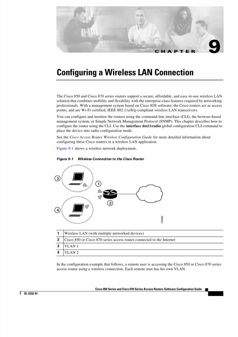
8/11/2019 Cisco 850 Series and Cisco 870 Series
http://slidepdf.com/reader/full/cisco-850-series-and-cisco-870-series 97/196

8/11/2019 Cisco 850 Series and Cisco 870 Series
http://slidepdf.com/reader/full/cisco-850-series-and-cisco-870-series 98/196

8/11/2019 Cisco 850 Series and Cisco 870 Series
http://slidepdf.com/reader/full/cisco-850-series-and-cisco-870-series 99/196
9-3Cisco 850 Series and Cisco 870 Series Access Routers Software Configuration Guide
OL-5332-01
Chapter 9 Configuring a Wireless LAN Connection Configure the Root Radio Station
Step 3 encryption method algorithm key
Example:Router(config-if)# encryption vlan 1 mode
ciphers tkipRouter(config-if)#
Specifies the encryption method, algorithm, andkey used to access the wireless interface.
The example uses the VLAN with optionalencryption method of data ciphers.
Step 4 ssid name
Example:Router(config-if)# ssid ciscoRouter(config-if-ssid)#
Creates a Service Set ID (SSID), the publicname of a wireless network.
Note All of the wireless devices on a WLANmust employ the same SSID tocommunicate with each other.
Step 5 vlan number
Example:Router(config-if-ssid)# vlan 1Router(config-if-ssid)#
Binds the SSID with a VLAN.
Step 6 authentication type
Example:Router(config-if-ssid)# authentication openRouter(config-if-ssid)# authenticationnetwork-eap eap_methodsRouter(config-if-ssid)# authenticationkey-management wpa
Sets the permitted authentication methods for auser attempting access to the wireless LAN.
More than one method can be specified, asshown in the example.
Step 7 exit
Example:Router(config-if-ssid)# exitRouter(config-if)#
Exits SSID configuration mode, and entersinterface configuration mode for the radiointerface.
Step 8 speed rate
Example:Router(config-if)# basic-1.0 basic-2.0basic-5.5 6.0 9.0 basic-11.0 12.0 18.0 24.036.0 48.0 54.0Router(config-if)#
(Optional) Specifies the required and allowedrates, in Mbps, for traffic over the wirelessconnection.
Step 9 rts [retries | threshold ]
Example:Router(config-if)# rts threshold 2312Router(config-if)#
(Optional) Specifies the Request to Send (RTS)threshold or the number of times to send arequest before determining the wireless LAN isunreachable.
Command Purpose

8/11/2019 Cisco 850 Series and Cisco 870 Series
http://slidepdf.com/reader/full/cisco-850-series-and-cisco-870-series 100/196
9-4Cisco 850 Series and Cisco 870 Series Access Routers Software Configuration Guide
OL-5332-01
Chapter 9 Configuring a Wireless LAN Connection Configure Bridging on VLANs
Configure Bridging on VLANsPerform these steps to configure integrated routing and bridging on VLANs, beginning in globalconfiguration mode:
Step 10 power [client | local ] [cck [number | maximum ] |ofdm [number | maximum ]]
Example:Router(config-if)# power local cck 50Router(config-if)# power local ofdm 30Router(config-if)#
(Optional) Specifies the radio transmitter powerlevel.
See the Cisco Access Router WirelessConfiguration Guide for available power levelvalues.
Step 11 channel [number | least-congested ]
Example:Router(config-if)# channel 2462Router(config-if)#
(Optional) Specifies the channel on whichcommunication occurs.
See the Cisco Access Router WirelessConfiguration Guide for available channelnumbers.
Step 12 station-role [repeater | root ]
Example:Router(config-if)# station-role rootRouter(config-if)#
(Optional) Specifies the role of this radiointerface.
You must specify at least one root interface.
Step 13 exit
Example:Router(config-if)# exitRouter(config)#
Exits interface configuration mode, and entersglobal configuration mode.
Command Purpose
Command or Action PurposeStep 1 bridge [number | crb | irb |mac-address-table ]
Example:Router(config)# bridge irbRouter(config)#
Specifies the type of bridging.
The example specifies integrated routing andbridging.
Step 2 interface name number
Example:Router(config)# interface vlan 1Router(config)#
Enters interface configuration mode.We want to set up bridging on the VLANs, so theexample enters the VLAN interfaceconfiguration mode.

8/11/2019 Cisco 850 Series and Cisco 870 Series
http://slidepdf.com/reader/full/cisco-850-series-and-cisco-870-series 101/196
9-5Cisco 850 Series and Cisco 870 Series Access Routers Software Configuration Guide
OL-5332-01
Chapter 9 Configuring a Wireless LAN Connection Configure Bridging on VLANs
Repeat Step 2 through Step 7 above for each VLAN that requires a wireless interface.
Step 3 bridge-group number
Example:Router(config)# bridge-group 1
Router(config)#
Assigns a bridge group to the interface.
Step 4 bridge-group number parameter
Example:Router(config)# bridge-group 1spanning-disabledRouter(config)#
Sets other bridge parameters for the bridginginterface.
Step 5 interface name number
Example:Router(config)# interface bvi 1Router(config)#
Enters configuration mode for the virtual bridgeinterface.
Step 6 bridge number route protocol
Example:Router (config) # bridge 1 route ipRouter(config)#
Specifies the protocol for the bridge group.
Step 7 ip address address mask
Example:Router(config)# ip address 10.0.1.1
255.255.255.0Router(config)#
Specifies the address for the virtual bridgeinterface.
Command or Action Purpose

8/11/2019 Cisco 850 Series and Cisco 870 Series
http://slidepdf.com/reader/full/cisco-850-series-and-cisco-870-series 102/196
9-6Cisco 850 Series and Cisco 870 Series Access Routers Software Configuration Guide
OL-5332-01
Chapter 9 Configuring a Wireless LAN Connection Configure Radio Station Subinterfaces
Configure Radio Station SubinterfacesPerform these steps to configure subinterfaces for each root station, beginning in global configurationmode:
Command Purpose
Step 1 interface type number
Example:Router(config)# interface dot11radio 0.1Router(config-subif)#
Enters subinterface configuration mode for theroot station interface.
Step 2 description string
Example:Router(config-subif)# description Cisco openRouter(config-subif)#
Provides a description of the subinterface for theadministrative user.
Step 3 encapsulation dot1q vlanID [native |second-dot1q ]
Example:Router(config-subif)# encapsulation dot1q 1nativeRouter(config-subif)#
Specifies that IEEE 802.1Q (dot1q)encapsulation is used on the specifiedsubinterface.
Step 4 no cdp enable
Example:Router(config-subif)# no cdp enableRouter(config-subif)#
Disables the Cisco Discovery Protocol (CDP) onthe wireless interface.

8/11/2019 Cisco 850 Series and Cisco 870 Series
http://slidepdf.com/reader/full/cisco-850-series-and-cisco-870-series 103/196
9-7Cisco 850 Series and Cisco 870 Series Access Routers Software Configuration Guide
OL-5332-01
Chapter 9 Configuring a Wireless LAN Connection Configuration Example
Repeat these steps to configure more subinterfaces, as needed.
Configuration ExampleThe following configuration example shows a portion of the configuration file for the wireless LANscenario described in the preceding sections.!bridge irb!interface Dot11Radio0 no ip address ! broadcast-key vlan 1 change 45 ! ! encryption vlan 1 mode ciphers tkip
! ssid cisco vlan 1
authentication open wpa-psk ascii 0 cisco123 authentication key-management wpa ! ssid ciscowep vlan 2 authentication open
! ssid ciscowpa vlan 3 authentication open
Step 5 bridge-group number
Example:Router(config-subif)# bridge-group 1
Router(config-subif)#
Assigns a bridge group to the subinterface.
Note When the bridge-group command isenabled, the following commands areautomatically enabled, and cannot bedisabled. If you disable these commandsyou may experience an interruption inwireless device communication.
bridge-group 1subscriber-loop-control
bridge-group 1 spanning-disabled
bridge-group 1block-unknown-source
Step 6 exit
Example:Router(config-subif)# exitRouter(config)#
Exits subinterface configuration mode, andenters global configuration mode.
Command Purpose
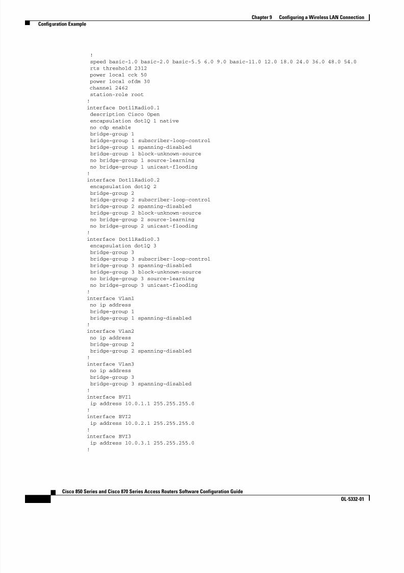
8/11/2019 Cisco 850 Series and Cisco 870 Series
http://slidepdf.com/reader/full/cisco-850-series-and-cisco-870-series 104/196
9-8Cisco 850 Series and Cisco 870 Series Access Routers Software Configuration Guide
OL-5332-01
Chapter 9 Configuring a Wireless LAN Connection Configuration Example
! speed basic-1.0 basic-2.0 basic-5.5 6.0 9.0 basic-11.0 12.0 18.0 24.0 36.0 48.0 54.0 rts threshold 2312 power local cck 50 power local ofdm 30 channel 2462 station-role root
!interface Dot11Radio0.1 description Cisco Open encapsulation dot1Q 1 native no cdp enable bridge-group 1 bridge-group 1 subscriber-loop-control bridge-group 1 spanning-disabled bridge-group 1 block-unknown-source no bridge-group 1 source-learning no bridge-group 1 unicast-flooding!interface Dot11Radio0.2 encapsulation dot1Q 2 bridge-group 2
bridge-group 2 subscriber-loop-control bridge-group 2 spanning-disabled bridge-group 2 block-unknown-source no bridge-group 2 source-learning no bridge-group 2 unicast-flooding!interface Dot11Radio0.3 encapsulation dot1Q 3 bridge-group 3 bridge-group 3 subscriber-loop-control bridge-group 3 spanning-disabled bridge-group 3 block-unknown-source no bridge-group 3 source-learning no bridge-group 3 unicast-flooding!interface Vlan1 no ip address bridge-group 1 bridge-group 1 spanning-disabled!interface Vlan2 no ip address bridge-group 2 bridge-group 2 spanning-disabled!interface Vlan3 no ip address bridge-group 3 bridge-group 3 spanning-disabled!interface BVI1 ip address 10.0.1.1 255.255.255.0!interface BVI2 ip address 10.0.2.1 255.255.255.0!interface BVI3 ip address 10.0.3.1 255.255.255.0!
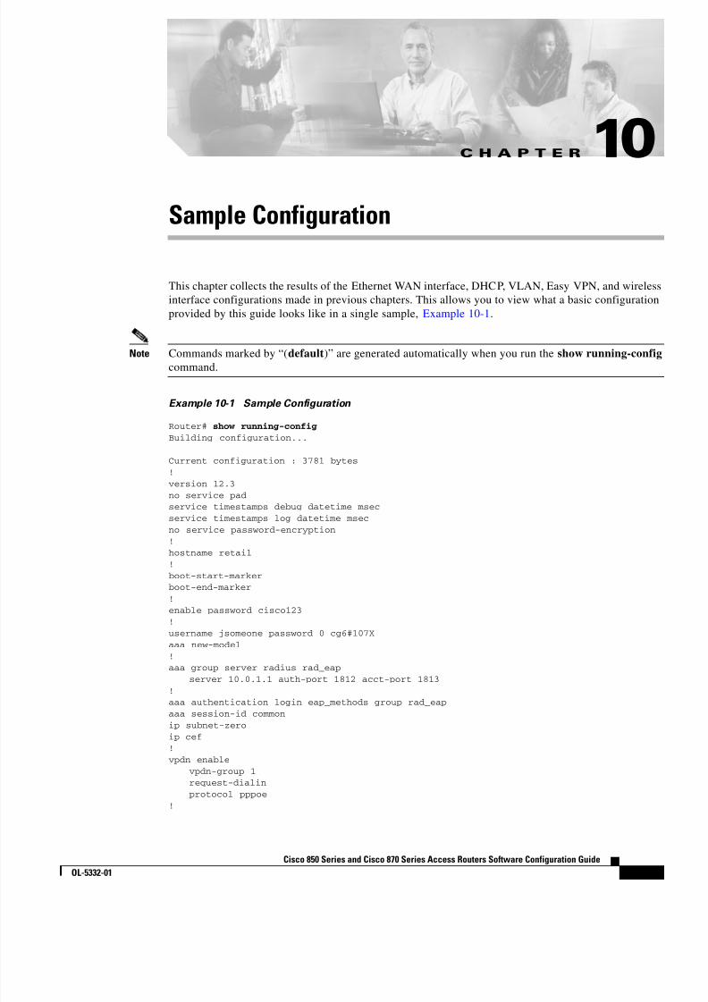
8/11/2019 Cisco 850 Series and Cisco 870 Series
http://slidepdf.com/reader/full/cisco-850-series-and-cisco-870-series 105/196
C H A P T E R
10-1Cisco 850 Series and Cisco 870 Series Access Routers Software Configuration Guide
OL-5332-01
10Sample Configuration
This chapter collects the results of the Ethernet WAN interface, DHCP, VLAN, Easy VPN, and wirelessinterface configurations made in previous chapters. This allows you to view what a basic configurationprovided by this guide looks like in a single sample, Example 10-1 .
Note Commands marked by “( default )” are generated automatically when you run the show running-configcommand.
Example 10-1 Sample Configuration
Router# show running-configBuilding configuration...
Current configuration : 3781 bytes!version 12.3no service padservice timestamps debug datetime msecservice timestamps log datetime msecno service password-encryption!hostname retail!boot-start-markerboot-end-marker!enable password cisco123!username jsomeone password 0 cg6#107Xaaa new-model!aaa group server radius rad_eap
server 10.0.1.1 auth-port 1812 acct-port 1813!
aaa authentication login eap_methods group rad_eapaaa session-id commonip subnet-zeroip cef!vpdn enable
vpdn-group 1request-dialinprotocol pppoe
!

8/11/2019 Cisco 850 Series and Cisco 870 Series
http://slidepdf.com/reader/full/cisco-850-series-and-cisco-870-series 106/196
10-2Cisco 850 Series and Cisco 870 Series Access Routers Software Configuration Guide
OL-5332-01
Chapter 10 Sample Configuration
interface dialer 1ip address negotiatedppp authentication chapdialer pool 1dialer-group 1
!dialer-list 1 protocol ip permit
ip nat inside source list 1 interface dialer 0 overloadip classless ( default )ip route 10.10.25.2 0.255.255.255 dialer 0
!ip dhcp excluded-address 10.0.1.1 10.0.1.10ip dhcp excluded-address 10.0.2.1 10.0.2.10ip dhcp excluded-address 10.0.3.1 10.0.3.10!ip dhcp pool vlan1 network 10.0.1.0 255.255.255.0 default-router 10.0.1.1!ip dhcp pool vlan2 network 10.0.2.0 255.255.255.0 default-router 10.0.2.1
!ip dhcp pool vlan3 network 10.0.3.0 255.255.255.0 default-router 10.0.3.1!ip ips po max-events 100no ftp-server write-enable!bridge irb!interface FastEthernet0
no ip address!interface FastEthernet1
no ip address!interface FastEthernet2
no ip address!interface FastEthernet3
switchport mode trunkno ip address
!interface FastEthernet4
ip address 192.168.12.2 255.255.255.0no ip directed-broadcast ( default )speed autoip nat outsideip access-group 103 inno cdp enablecrypto ipsec client ezvpn ezvpnclient outsidecrypto map static-map
!crypto isakmp policy 1
encryption 3desauthentication pre-sharegroup 2lifetime 480
!

8/11/2019 Cisco 850 Series and Cisco 870 Series
http://slidepdf.com/reader/full/cisco-850-series-and-cisco-870-series 107/196

8/11/2019 Cisco 850 Series and Cisco 870 Series
http://slidepdf.com/reader/full/cisco-850-series-and-cisco-870-series 108/196
10-4Cisco 850 Series and Cisco 870 Series Access Routers Software Configuration Guide
OL-5332-01
Chapter 10 Sample Configuration
interface Dot11Radio0.2encapsulation dot1Q 2bridge-group 2bridge-group 2 subscriber-loop-controlbridge-group 2 spanning-disabledbridge-group 2 block-unknown-sourceno bridge-group 2 source-learning
no bridge-group 2 unicast-flooding!interface Dot11Radio0.3
encapsulation dot1Q 3bridge-group 3bridge-group 3 subscriber-loop-controlbridge-group 3 spanning-disabledbridge-group 3 block-unknown-sourceno bridge-group 3 source-learningno bridge-group 3 unicast-flooding
!interface Vlan1
ip address 192.168.1.1 255.255.255.0no ip directed-broadcast ( default )ip nat inside
crypto ipsec client ezvpn ezvpnclient insideip inspect firewall inno cdp enablebridge-group 1bridge-group 1 spanning-disabled
!interface Vlan2
no ip addressbridge-group 2bridge-group 2 spanning-disabled
!interface Vlan3
no ip addressbridge-group 3bridge-group 3 spanning-disabled
!interface BVI1
ip address 10.0.1.1 255.255.255.0!interface BVI2
ip address 10.0.2.1 255.255.255.0!interface BVI3
ip address 10.0.3.1 255.255.255.0!ip classless!ip http serverno ip http secure-server!radius-server local
nas 10.0.1.1 key 0 cisco123group rad_eap
!user jsomeone nthash 7 0529575803696F2C492143375828267C7A760E1113734624452725707C010B065Buser AMER\jsomeone nthash 70224550C29232E041C6A5D3C5633305D5D560C09027966167137233026580E0B0D!radius-server host 10.0.1.1 auth-port 1812 acct-port 1813 key cisco123!control-plane!

8/11/2019 Cisco 850 Series and Cisco 870 Series
http://slidepdf.com/reader/full/cisco-850-series-and-cisco-870-series 109/196
10-5Cisco 850 Series and Cisco 870 Series Access Routers Software Configuration Guide
OL-5332-01
Chapter 10 Sample Configuration
bridge 1 route ipbridge 2 route ipbridge 3 route ip!ip inspect name firewall tcpip inspect name firewall udpip inspect name firewall rtsp
ip inspect name firewall h323ip inspect name firewall netshow ip inspect name firewall ftpip inspect name firewall sqlnet!access-list 103 permit udp host 200.1.1.1 any eq isakmpaccess-list 103 permit udp host 200.1.1.1 eq isakmp anyaccess-list 103 permit esp host 200.1.1.1 anyaccess-list 103 permit icmp any anyaccess-list 103 deny ip any anyaccess-list 105 permit ip 10.1.1.0 0.0.0.255 192.168.0.0 0.0.255.255no cdp run!line con 0
password cisco123
no modem enabletransport preferred alltransport output all
line aux 0transport preferred alltransport output all
line vty 0 4password cisco123transport preferred alltransport input alltransport output all
!

8/11/2019 Cisco 850 Series and Cisco 870 Series
http://slidepdf.com/reader/full/cisco-850-series-and-cisco-870-series 110/196
10-6Cisco 850 Series and Cisco 870 Series Access Routers Software Configuration Guide
OL-5332-01
Chapter 10 Sample Configuration

8/11/2019 Cisco 850 Series and Cisco 870 Series
http://slidepdf.com/reader/full/cisco-850-series-and-cisco-870-series 111/196

8/11/2019 Cisco 850 Series and Cisco 870 Series
http://slidepdf.com/reader/full/cisco-850-series-and-cisco-870-series 112/196
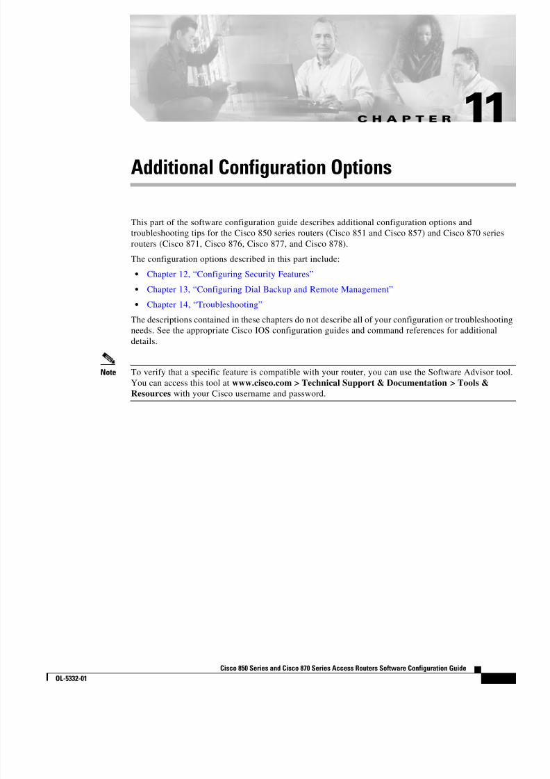
8/11/2019 Cisco 850 Series and Cisco 870 Series
http://slidepdf.com/reader/full/cisco-850-series-and-cisco-870-series 113/196

8/11/2019 Cisco 850 Series and Cisco 870 Series
http://slidepdf.com/reader/full/cisco-850-series-and-cisco-870-series 114/196
11-2Cisco 850 Series and Cisco 870 Series Access Routers Software Configuration Guide
OL-5332-01
Chapter 11 Additional Configuration Options
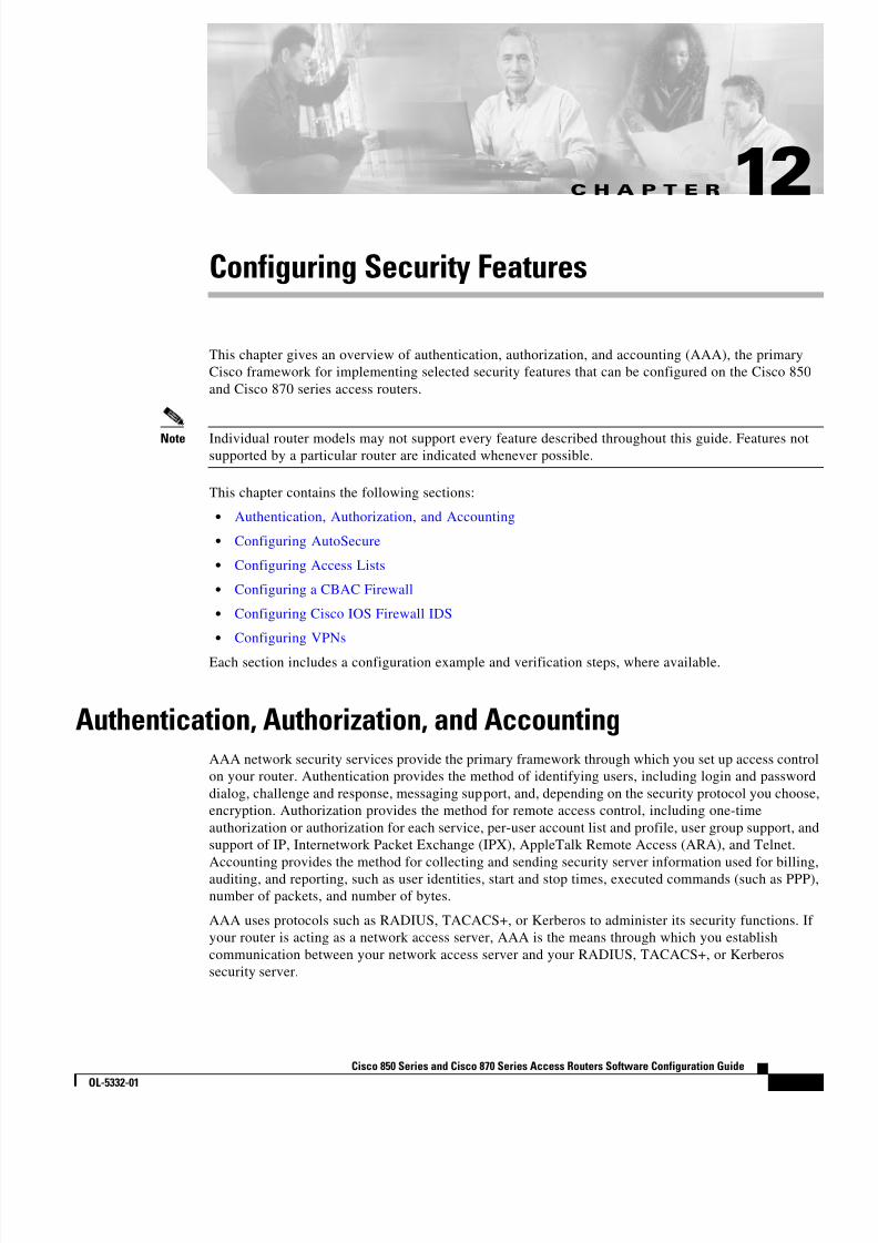
8/11/2019 Cisco 850 Series and Cisco 870 Series
http://slidepdf.com/reader/full/cisco-850-series-and-cisco-870-series 115/196
C H A P T E R
12-1Cisco 850 Series and Cisco 870 Series Access Routers Software Configuration Guide
OL-5332-01
12Configuring Security Features
This chapter gives an overview of authentication, authorization, and accounting (AAA), the primaryCisco framework for implementing selected security features that can be configured on the Cisco 850and Cisco 870 series access routers.
Note Individual router models may not support every feature described throughout this guide. Features notsupported by a particular router are indicated whenever possible.
This chapter contains the following sections:
• Authentication, Authorization, and Accounting
• Configuring AutoSecure
• Configuring Access Lists
• Configuring a CBAC Firewall
• Configuring Cisco IOS Firewall IDS
• Configuring VPNs
Each section includes a configuration example and verification steps, where available.
Authentication, Authorization, and AccountingAAA network security services provide the primary framework through which you set up access controlon your router. Authentication provides the method of identifying users, including login and passworddialog, challenge and response, messaging support, and, depending on the security protocol you choose,encryption. Authorization provides the method for remote access control, including one-timeauthorization or authorization for each service, per-user account list and profile, user group support, andsupport of IP, Internetwork Packet Exchange (IPX), AppleTalk Remote Access (ARA), and Telnet.Accounting provides the method for collecting and sending security server information used for billing,auditing, and reporting, such as user identities, start and stop times, executed commands (such as PPP),number of packets, and number of bytes.
AAA uses protocols such as RADIUS, TACACS+, or Kerberos to administer its security functions. Ifyour router is acting as a network access server, AAA is the means through which you establishcommunication between your network access server and your RADIUS, TACACS+, or Kerberossecurity server.
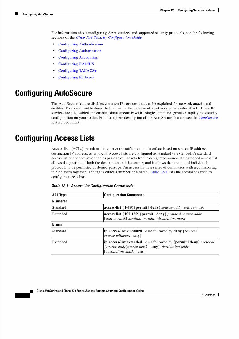
8/11/2019 Cisco 850 Series and Cisco 870 Series
http://slidepdf.com/reader/full/cisco-850-series-and-cisco-870-series 116/196

8/11/2019 Cisco 850 Series and Cisco 870 Series
http://slidepdf.com/reader/full/cisco-850-series-and-cisco-870-series 117/196
8/11/2019 Cisco 850 Series and Cisco 870 Series
http://slidepdf.com/reader/full/cisco-850-series-and-cisco-870-series 118/196
12-4Cisco 850 Series and Cisco 870 Series Access Routers Software Configuration Guide
OL-5332-01
Chapter 12 Configuring Security Features Configuring Cisco IOS Firewall IDS
Configuring Cisco IOS Firewall IDSCisco IOS Firewall Intrusion Detection System (IDS) technology enhances perimeter firewall protectionby taking appropriate action on packets and flows that violate the security policy or represent maliciousnetwork activity.
Cisco IOS Firewall IDS identifies 59 of the most common attacks using “signatures” to detect patternsof misuse in network traffic. It acts as an in-line intrusion detection sensor, watching packets andsessions as they flow through the router, scanning each to match any of the IDS signatures. When itdetects suspicious activity, it responds before network security can be compromised, logs the event, and,depending on configuration, sends an alarm, drops suspicious packets, or resets the TCP connection.
For additional information about configuring Cisco IOS Firewall IDS, see the “ Configuring Cisco IOSFirewall Intrusion Detection System ” section of the Cisco IOS Release 12.3 Security ConfigurationGuide .
Configuring VPNsA virtual private network (VPN) connection provides a secure connection between two networks over apublic network such as the Internet. Cisco 850 and Cisco 870 series access routers support site-to-siteVPNs using IP security (IPSec) tunnels and generic routing encapsulation (GRE). Permanent VPNconnections between two peers, or dynamic VPNs using EZVPN or DMVPN which create and tear downVPN connections as needed, can be configured. Chapter 6, “Configuring a VPN Using Easy VPN andan IPSec Tunnel,” and Chapter 7, “Configuring VPNs Using an IPSec Tunnel and Generic RoutingEncapsulation,” show examples of how to configure your router with these features. For moreinformation about IPSec and GRE configuration, see the “ Configuring IPSec Network Security ” chapterof the Cisco IOS Release 12.3 Security Configuration Guide .
For information about additional VPN configurations supported by Cisco 850 and Cisco 870 seriesaccess routers, see the following feature documents:
• EZVPN Server —Cisco 870 series routers can be configured to act as EZVPN servers, lettingauthorized EZVPN clients establish dynamic VPN tunnels to the connected network.
• Dynamic Multipoint VPN (DMVPN) —The DMVPN feature creates VPN tunnels between multiplerouters in a multipoint configuration as needed, simplifying the configuration and eliminating theneed for permanent, point-to-point VPN tunnels.

8/11/2019 Cisco 850 Series and Cisco 870 Series
http://slidepdf.com/reader/full/cisco-850-series-and-cisco-870-series 119/196

8/11/2019 Cisco 850 Series and Cisco 870 Series
http://slidepdf.com/reader/full/cisco-850-series-and-cisco-870-series 120/196
13-2Cisco 850 Series and Cisco 870 Series Access Routers Software Configuration Guide
OL-5332-01
Chapter 13 Configuring Dial Backup and Remote Management Dial Backup Feature Activation Methods
Backup InterfacesWhen the router receives an indication that the primary line is down, a backup interface is brought up.You can configure the backup interface to go down once the primary connection has been restored for aspecified period.
This is accomplished using dial-on-demand routing (DDR). When this is configured, a backup call istriggered by specified traffic.
Note Even if the backup interface comes out of standby mode (is brought up), the router does not trigger thebackup call unless it receives the specified traffic for that backup interface.
Configuring Backup Interfaces
Perform these steps to configure your router with a backup interface, beginning in global configurationmode:
Command Purpose
Step 1 interface type number
Example:Router(config)# interface atm 0Router(config-if)#
Enters interface configuration mode for theinterface for which you want to configure backup.
This can be a serial interface, ISDN interface, orasynchronous interface.
The example shows the configuration of a backupinterface for an ATM WAN connection.
Step 2 backup interface interface-typeinterface-number
Example:Router(config-if)# backup interface bri 0Router(config-if)#
Assigns an interface as the secondary, or backupinterface.
This can be a serial interface or asynchronousinterface. For example, a serial 1 interface couldbe configured to back up a serial 0 interface.
The example shows a Basic Rate Interfaceconfigured as the backup interface for the ATM 0interface.
Step 3 exit
Example:Router(config-if)# exitRouter(config)#
Enters global configuration mode.
Floating Static RoutesFloating static routes provide alternative routes for traffic. Floating static routes are not activated unlessa DDR backup call has been triggered by specified traffic for a backup interface.
Floating static routes are independent of line protocol status. This is an important consideration forFrame Relay circuits because the line protocol may not go down if the data-link connection identifier(DLCI) is inactive. Floating static routes are also encapsulation independent.

8/11/2019 Cisco 850 Series and Cisco 870 Series
http://slidepdf.com/reader/full/cisco-850-series-and-cisco-870-series 121/196
13-3Cisco 850 Series and Cisco 870 Series Access Routers Software Configuration Guide
OL-5332-01
Chapter 13 Configuring Dial Backup and Remote Management Dial Backup Feature Activation Methods
Note When static routes are configured, the primary interface protocol must go down in order to activate thefloating static route.
Configuring Floating Static RoutesStatic and dynamic routes are the two components of floating static routes. Perform these steps toconfigure the static and dynamic routes on your router, beginning in global configuration mode:
Command Purpose
Step 1 ip route prefix mask { ip-address | interface-type interface-number [ ip-address ]}
Example:Router(config)# ip route 0.0.0.0 0.0.0.022.0.0.2
Router(config)#
Assigns the primary static route.
Step 2 ip route prefix mask {ip-address | interface-type interface-number [ ip-address ]} [ distance ]
Example:Router(config)# ip route 0.0.0.0 0.0.0.0192.168.2.2 150Router(config)#
Assigns the lower routing administrative distancevalue for the backup interface route. 192.168.2.2is the peer IP address of the backup interface.
Step 3 router rip
Example:Router(config)# router ripRouter(config)#
Enables RIP routing.
Step 4 network ip-address
Example:Router(config)# network 22.0.0.0Router(config)#
Defines the primary interface network. 22.0.0.0 isthe network value of the primary interface.
Step 5 ip route prefix mask {ip-address | interface-typeinterface-number [ ip-address ]} [ distance ]
Example:Router(config)# ip route 0.0.0.0 0.0.0.0192.168.2.2 150Router(config)#
Assigns the lower routing administrative distancevalue for the backup interface route. 192.168.2.2is the peer IP address of the backup interface.

8/11/2019 Cisco 850 Series and Cisco 870 Series
http://slidepdf.com/reader/full/cisco-850-series-and-cisco-870-series 122/196
13-4Cisco 850 Series and Cisco 870 Series Access Routers Software Configuration Guide
OL-5332-01
Chapter 13 Configuring Dial Backup and Remote Management Dial Backup Feature Activation Methods
Note When dynamic routes are being used, the time it takes to activate a floating static route depends on therouting protocol convergence times.
Dialer WatchThe dialer watch method only supports the Extended Interior Gateway Routing Protocol (EIGRP)link-state dynamic routing protocols.
Configuring Dialer Watch
Perform these steps to configure a dialer watch on your router, beginning in global configuration mode:
Command Purpose
Step 1 interface type number
Example:Router(config)# interface dialer 2Router(config-if)#
Enters configuration mode for the dial backupinterface.
Step 2 dialerwatch-group group-number
Example:Router(config-if)# dialer watch-group 2Router(config-if)#
Specifies the group number for the watch list.
Step 3 exit
Example:Router(config-if)# exitRouter(config)#
Enters global configuration mode.
Step 4 ip route prefix mask {ip-address | interface-type interface-number [ ip-address ]}
Example:Router(config)# ip route 0.0.0.0 0.0.0.022.0.0.2Router(config)#
Assigns the primary route. 22.0.0.2 is the peer IPaddress of the primary interface.

8/11/2019 Cisco 850 Series and Cisco 870 Series
http://slidepdf.com/reader/full/cisco-850-series-and-cisco-870-series 123/196
13-5Cisco 850 Series and Cisco 870 Series Access Routers Software Configuration Guide
OL-5332-01
Chapter 13 Configuring Dial Backup and Remote Management Dial Backup Feature Limitations
Dial Backup Feature LimitationsThe following limitations exist for the dial backup feature:
• Bridging is not supported over console or auxiliary port backup interfaces.
• For the Cisco 851 router, only dial-in capability is supported.
• Dial backup support on the Cisco 871 router is limited because the Ethernet WAN interface is alwaysup, even when ISP connectivity is down on the other side of the modem connected to the Cisco 871router. The router must be in a PPPoE environment with the dialer watch feature running. The IPaddresses of the peer must be specified in the dialer watch and the static route commands to enabledial backup when the primary line goes down.
Table 13-1 summarizes dial backup support and limitations for the Cisco 800 series access routers.
Step 5 ip route prefix mask {ip-address | interface-type interface-number [ ip-address ]} [ distance ]
Example:Router(config)# ip route 0.0.0.0 0.0.0.0192.168.2.2 150Router(config)#
Assigns the lower routing administrative distancevalue for the backup interface route. 192.168.2.2is the peer IP address of the backup interface.
Step 6 dialerwatch-list group-number {ip ip-addressaddress-mask | delay route-check initial seconds }
Example:Router(config)# dialer watch-list 2 ip22.0.0.2 255.255.255.255Router(config)#
Assigns an IP address to the watch list.
If the connection on the primary interface is lostand the IP address is unavailable on the router, thedial-out feature on the backup interface istriggered. 22.0.0.2 is the peer IP address of theprimary interface.
Command Purpose
Table 13-1 Dial Backup Feature Support and Limitations Summary
WAN EncapsulationType
Dial BackupPossible? Dial Backup Method Limitations
Cisco 851 or 871
PPPoE Yes Dialer watch Bridging is not supported across a slow interface, forexample, an auxiliary port. The peer IP address of the ISP isneeded to configure the dialerwatch command and the IPstatic route.
Normal IP in cablemodem scenario
No Dialer watch The IP addresses of the peers are needed for dialer watch towork properly. If a lease time obtained by DHCP is not setshort enough (1 or 2 minutes), dial backup will not besupported.

8/11/2019 Cisco 850 Series and Cisco 870 Series
http://slidepdf.com/reader/full/cisco-850-series-and-cisco-870-series 124/196
13-6Cisco 850 Series and Cisco 870 Series Access Routers Software Configuration Guide
OL-5332-01
Chapter 13 Configuring Dial Backup and Remote Management Dial Backup Feature Limitations
Configuration ExampleThe following three examples show sample configurations for the three dial backup methods.
Example 13-1 Configuring Dial Backup Using Backup Interfaces
!vpdn enable
!vpdn-group 1 accept-dialin protocol pppoe!! Specifies the ISDN switch typeisdn switch-type basic-net3!interface vlan 1 ip address 192.168.1.1 255.255.255.0 hold-queue 100 out!! ISDN interface to be used as a backup interfaceinterface BRI0 no ip address
encapsulation ppp dialer pool-member 1 isdn switch-type basic-net3!interface ATM0 backup interface BRI0 no ip address no atm ilmi-keepalive pvc 1/40 encapsulation aal5snap pppoe-client dial-pool-number 2
Cisco 876, 877, or 878
PPP over ATMPPP over Ethernet
Yes Backup interfacesFloating static routes
Dialer watch
Floating static route and dialer watch need a routing protocolto run in the router. The dialer watch method brings up thebackup interface as soon as the primary link goes down. Thebackup interface is brought down as soon as the dialertimeout is reached and the primary interface is up. The routerchecks the primary interface only when the dialer timeoutexpires. The backup interface remains up until the dialertimeout is reached, even though the primary interface is up.
For the dialer watch method, a routing protoco l does not needto be running in the router, if the IP address of the peer isknown.
RFC 1483 (AAL5,
SNAP, and MUX)
Yes Backup interfaces
Floating static routes
Dialer watch
If bridging is done through the WAN interface, it is not
supported across the auxiliary port.
Table 13-1 Dial Backup Feature Support and Limitations Summary (continued)
WAN EncapsulationType
Dial BackupPossible? Dial Backup Method Limitations
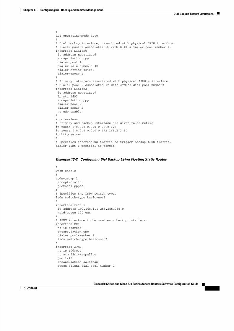
8/11/2019 Cisco 850 Series and Cisco 870 Series
http://slidepdf.com/reader/full/cisco-850-series-and-cisco-870-series 125/196
13-7Cisco 850 Series and Cisco 870 Series Access Routers Software Configuration Guide
OL-5332-01
Chapter 13 Configuring Dial Backup and Remote Management Dial Backup Feature Limitations
!dsl operating-mode auto!! Dial backup interface, associated with physical BRI0 interface.! Dialer pool 1 associates it with BRI0’s dialer pool member 1.interface Dialer0 ip address negotiated
encapsulation ppp dialer pool 1 dialer idle-timeout 30 dialer string 384040 dialer-group 1!! Primary interface associated with physical ATM0’s interface.! Dialer pool 2 associates it with ATM0’s dial-pool-number2.interface Dialer2 ip address negotiated ip mtu 1492 encapsulation ppp dialer pool 2 dialer-group 2 no cdp enable
!ip classless! Primary and backup interface are given route metricip route 0.0.0.0 0.0.0.0 22.0.0.2ip route 0.0.0.0 0.0.0.0 192.168.2.2 80ip http server!! Specifies interesting traffic to trigger backup ISDN traffic.dialer-list 1 protocol ip permit
Example 13-2 Configuring Dial Backup Using Floating Static Routes
!vpdn enable
!vpdn-group 1 accept-dialin protocol pppoe!! Specifies the ISDN switch type.isdn switch-type basic-net3!interface vlan 1 ip address 192.168.1.1 255.255.255.0 hold-queue 100 out!! ISDN interface to be used as a backup interface.interface BRI0 no ip address
encapsulation ppp dialer pool-member 1 isdn switch-type basic-net3!interface ATM0 no ip address no atm ilmi-keepalive pvc 1/40 encapsulation aal5snap pppoe-client dial-pool-number 2

8/11/2019 Cisco 850 Series and Cisco 870 Series
http://slidepdf.com/reader/full/cisco-850-series-and-cisco-870-series 126/196
13-8Cisco 850 Series and Cisco 870 Series Access Routers Software Configuration Guide
OL-5332-01
Chapter 13 Configuring Dial Backup and Remote Management Dial Backup Feature Limitations
!dsl operating-mode auto!! Dial backup interface, associated with physical BRI0 interface.! Dialer pool 1 associates it with BRI0’s dialer pool member 1interface Dialer0 ip address negotiated
encapsulation ppp dialer pool 1 dialer idle-timeout 30 dialer string 384040 dialer-group 1!! Primary interface associated with physical ATM0’s interface.! Dialer pool 2 associates it with ATM0’s dial-pool-number2.interface Dialer2 ip address negotiated ip mtu 1492 encapsulation ppp dialer pool 2 dialer-group 2!
ip classlessno cdp enable! Primary and backup interface are given route metric. (This example uses static routes,! thus atm0 line protocol must be brought down for backup interface to function.)ip route 0.0.0.0 0.0.0.0 22.0.0.2ip route 0.0.0.0 0.0.0.0 192.168.2.2 150ip http server!! Specifies interesting traffic to trigger backup ISDN traffic.dialer-list 1 protocol ip permit
Example 13-3 Configuring Dial Backup Using Dialer Watch
!
vpdn enable!vpdn-group 1 accept-dialin protocol pppoe!! Specifies the ISDN switch type.isdn switch-type basic-net3!interface Ethernet0 ip address 192.168.1.1 255.255.255.0 hold-queue 100 out!! ISDN interface to be used as a backup interface.interface BRI0
no ip address encapsulation ppp dialer pool-member 1 isdn switch-type basic-net3!interface ATM0 no ip address no atm ilmi-keepalive pvc 1/40 encapsulation aal5snap pppoe-client dial-pool-number 2
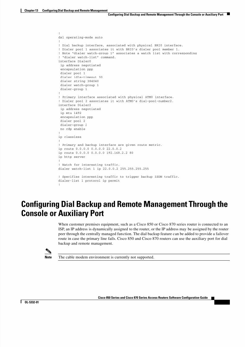
8/11/2019 Cisco 850 Series and Cisco 870 Series
http://slidepdf.com/reader/full/cisco-850-series-and-cisco-870-series 127/196
13-9Cisco 850 Series and Cisco 870 Series Access Routers Software Configuration Guide
OL-5332-01
Chapter 13 Configuring Dial Backup and Remote Management Configuring Dial Backup and Remote Management Through the Console or Auxiliary Port
!dsl operating-mode auto!! Dial backup interface, associated with physical BRI0 interface.! Dialer pool 1 associates it with BRI0’s dialer pool member 1.! Note “dialer watch-group 1” associates a watch list with corresponding! “dialer watch-list” command.
interface Dialer0 ip address negotiated encapsulation ppp dialer pool 1 dialer idle-timeout 30 dialer string 384040 dialer watch-group 1 dialer-group 1!! Primary interface associated with physical ATM0 interface.! Dialer pool 2 associates it with ATM0’s dial-pool-number2.interface Dialer2 ip address negotiated ip mtu 1492 encapsulation ppp
dialer pool 2 dialer-group 2 no cdp enable!ip classless!! Primary and backup interface are given route metric.ip route 0.0.0.0 0.0.0.0 22.0.0.2ip route 0.0.0.0 0.0.0.0 192.168.2.2 80ip http server!! Watch for interesting traffic.dialer watch-list 1 ip 22.0.0.2 255.255.255.255
! Specifies interesting traffic to trigger backup ISDN traffic.dialer-list 1 protocol ip permit!
Configuring Dial Backup and Remote Management Through theConsole or Auxiliary Port
When customer premises equipment, such as a Cisco 850 or Cisco 870 series router is connected to anISP, an IP address is dynamically assigned to the router, or the IP address may be assigned by the routerpeer through the centrally managed function. The dial backup feature can be added to provide a failoverroute in case the primary line fails. Cisco 850 and Cisco 870 routers can use the auxiliary port for dial
backup and remote management.
Note The cable modem environment is currently not supported.

8/11/2019 Cisco 850 Series and Cisco 870 Series
http://slidepdf.com/reader/full/cisco-850-series-and-cisco-870-series 128/196
13-10Cisco 850 Series and Cisco 870 Series Access Routers Software Configuration Guide
OL-5332-01
Chapter 13 Configuring Dial Backup and Remote Management Configuring Dial Backup and Remote Management Through the Console or Auxiliary Port
Figure 13-1 shows the network configuration used for remote management access and for providingbackup to the primary WAN line.
Figure 13-1 Dial Backup and Remote Management Through the Auxiliary Port
8 2 2 6 9
A1
3
2
2
C
B
BC
2
ATM
PSTN
1 Cisco 850 or Cisco 870series router
A Main WAN link; primary connection to Internet service provider
2 Modem B Dial backup; serves as a failover link for Cisco 870 routers whenprimary line goes down
3 PC C Remote management; serves as dial-in access to allow changes orupdates to Cisco IOS configurations
Configuration TasksPerform these steps to configure dial backup and remote management for these routers, beginning inglobal configuration mode:
Command Purpose
Step 1 ip name-server server-address
Example:Router(config)# ip name-server192.168.28.12Router(config)#
Enters your ISP DNS IP address.
Tip You may add multiple server addresses ifavailable.
Step 2 ip dhcp pool name
Example:Router(config)# ip dhcp pool 1Router(config-dhcp)#
Creates a DHCP address pool on the router andenters DHCP pool configuration mode. The name argument can be a string or an integer.
• Configure the DHCP address pool. Forsample commands you can use in DHCP poolconfiguration mode, see the “ConfigurationExample” section on page 13-13 .

8/11/2019 Cisco 850 Series and Cisco 870 Series
http://slidepdf.com/reader/full/cisco-850-series-and-cisco-870-series 129/196
13-11Cisco 850 Series and Cisco 870 Series Access Routers Software Configuration Guide
OL-5332-01
Chapter 13 Configuring Dial Backup and Remote Management Configuring Dial Backup and Remote Management Through the Console or Auxiliary Port
Step 3 exit
Example:Router(config-dhcp)# exit
Router(config)#
Enters global configuration mode.
Step 4 chat-script script-name expect-send
Example:Router(config)# chat-script Dialout ABORTERROR ABORT BUSY ““ “AT” OK “ATDT 5555102T” TIMEOUT 45 CONNECT \cRouter(config)#
Configures a chat script used in dial-on-demandrouting (DDR) to give commands to dial a modemand to log in to remote systems. The defined scriptis used to place a call over a modem.
Step 5 interface type number
Example:Router(config)# interface Async 1Router(config-if)#
Creates and enters configuration mode for theasynchronous interface.
• Configure the asynchronous interface. Forsample commands you can use in asyncinterface configuration mode, see the“Configuration Example” section onpage 13-13 .
Step 6 exit
Example:Router(config-if)# exitRouter(config)#
Enters global configuration mode.
Step 7 interface type number
Example:Router(config)# interface Dialer 3Router(config-if)#
Enters interface configuration mode.
Step 8 dialer watch-group group-number
Example:Router(config-if)# dialer watch-group 1Router(config-if)#
Specifies the group number for watch list.
Step 9 exit
Example:Router(config-if)# exitRouter(config)#
Enters global configuration mode.
Command Purpose

8/11/2019 Cisco 850 Series and Cisco 870 Series
http://slidepdf.com/reader/full/cisco-850-series-and-cisco-870-series 130/196
13-12Cisco 850 Series and Cisco 870 Series Access Routers Software Configuration Guide
OL-5332-01
Chapter 13 Configuring Dial Backup and Remote Management Configuring Dial Backup and Remote Management Through the Console or Auxiliary Port
Step 10 ip nat inside source {list access-list-number }{interface type number | pool name } [ overload ]
Example:Router(config)# ip nat inside source list101 interface Dialer 3 overload
Enables dynamic translation of addresses on theinside interface.
Step 11 ip route prefix mask {ip-address | interface-type interface-number [ ip-address ]}
Example:Router(config)# ip route 0.0.0.0 0.0.0.022.0.0.2Router(config)#
Sets the IP route to point to the dialer interface asa default gateway.
Step 12 access-list access-list-number {deny | permit } source [source-wildcard ]
Example:Router(config)# access-list 1 permit 192.168.0.0 0.0.255.255 any
Defines an extended access list that indicateswhich addresses need translation.
Step 13 dialerwatch-list group-number {ip ip-addressaddress-mask | delay route-check initial seconds }
Example:Router(config)# dialer watch-list 1 ip22.0.0.2 255.255.255.255
Router(config)#
Evaluates the status of the primary link, based onthe existence of routes to the peer. 22.0.0.2 is thepeer IP address of the ISP.
Step 14 line [aux | console | tty | vty ] line-number [ending-line-number ]
Example:Router(config)# line console 0Router(config-line)#
Enters configuration mode for the line interface.
Step 15 modem enable
Example:Router(config-line)# modem enableRouter(config-line)#
Switches the port from console to auxiliary portfunction.
Step 16 exit
Example:Router(config-line)# exitRouter(config)#
Enters global configuration mode.
Command Purpose
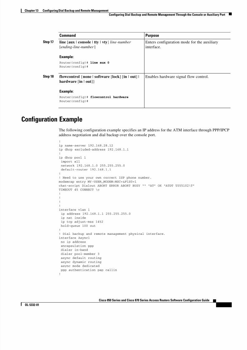
8/11/2019 Cisco 850 Series and Cisco 870 Series
http://slidepdf.com/reader/full/cisco-850-series-and-cisco-870-series 131/196

8/11/2019 Cisco 850 Series and Cisco 870 Series
http://slidepdf.com/reader/full/cisco-850-series-and-cisco-870-series 132/196
13-14Cisco 850 Series and Cisco 870 Series Access Routers Software Configuration Guide
OL-5332-01
Chapter 13 Configuring Dial Backup and Remote Management Configuring Dial Backup and Remote Management Through the Console or Auxiliary Port
interface ATM0 mtu 1492 no ip address no atm ilmi-keepalive pvc 0/35 pppoe-client dial-pool-number 1!
dsl operating-mode auto!! Primary WAN link.interface Dialer1 ip address negotiated ip nat outside encapsulation ppp dialer pool 1 ppp authentication pap callin ppp pap sent-username account password 7 pass ppp ipcp dns request ppp ipcp wins request ppp ipcp mask request!! Dialer backup logical interface.
interface Dialer3 ip address negotiated ip nat outside encapsulation ppp no ip route-cache no ip mroute-cache dialer pool 3 dialer idle-timeout 60 dialer string 5555102 modem-script Dialout dialer watch-group 1!! Remote management PC IP address.peer default ip address 192.168.2.2no cdp enable!! Need to use your own ISP account and password.ppp pap sent-username account password 7 passppp ipcp dns requestppp ipcp wins requestppp ipcp mask request!! IP NAT over Dialer interface using route-map.ip nat inside source route-map main interface Dialer1 overloadip nat inside source route-map secondary interface Dialer3 overloadip classless!! When primary link is up again, distance 50 will override 80 if dial backup! has not timed out. Use multiple routes because peer IP addresses are alternated! among them when the CPE is connected.ip route 0.0.0.0 0.0.0.0 64.161.31.254 50ip route 0.0.0.0 0.0.0.0 66.125.91.254 50ip route 0.0.0.0 0.0.0.0 64.174.91.254 50ip route 0.0.0.0 0.0.0.0 63.203.35.136 80ip route 0.0.0.0 0.0.0.0 63.203.35.137 80ip route 0.0.0.0 0.0.0.0 63.203.35.138 80ip route 0.0.0.0 0.0.0.0 63.203.35.139 80ip route 0.0.0.0 0.0.0.0 63.203.35.140 80ip route 0.0.0.0 0.0.0.0 63.203.35.141 80ip route 0.0.0.0 0.0.0.0 Dialer1 150no ip http serverip pim bidir-enable!

8/11/2019 Cisco 850 Series and Cisco 870 Series
http://slidepdf.com/reader/full/cisco-850-series-and-cisco-870-series 133/196
13-15Cisco 850 Series and Cisco 870 Series Access Routers Software Configuration Guide
OL-5332-01
Chapter 13 Configuring Dial Backup and Remote Management Configuring Dial Backup and Remote Management Through the Console or Auxiliary Port
! PC IP address behind CPE.access-list 101 permit ip 192.168.0.0 0.0.255.255 anyaccess-list 103 permit ip 192.168.0.0 0.0.255.255 any!! Watch multiple IP addresses because peers are alternated! among them when the CPE is connected.dialer watch-list 1 ip 64.161.31.254 255.255.255.255
dialer watch-list 1 ip 64.174.91.254 255.255.255.255dialer watch-list 1 ip 64.125.91.254 255.255.255.255!! Dial backup will kick in if primary link is not available! 5 minutes after CPE starts up.dialer watch-list 1 delay route-check initial 300dialer-list 1 protocol ip permit!! Direct traffic to an interface only if the dialer is assigned an IP address.route-map main permit 10 match ip address 101 match interface Dialer1!route-map secondary permit 10 match ip address 103
match interface Dialer3!! Change console to aux function.line con 0 exec-timedout 0 0 modem enable stopbits 1line aux 0 exec-timeout 0 0 ! To enable and communicate with the external modem properly. script dialer Dialout modem InOut modem autoconfigure discovery transport input all
stopbits 1 speed 115200 flowcontrol hardwareline vty 0 4 exec-timeout 0 0 password cisco login!scheduler max-task-time 5000end

8/11/2019 Cisco 850 Series and Cisco 870 Series
http://slidepdf.com/reader/full/cisco-850-series-and-cisco-870-series 134/196
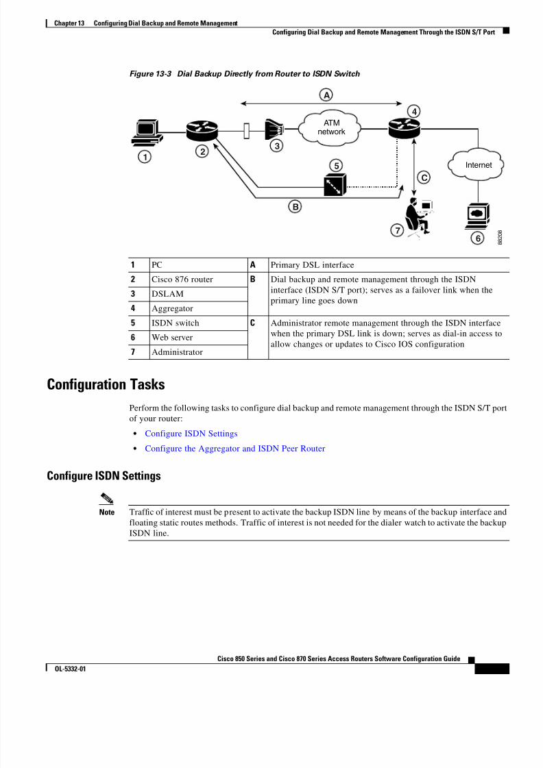
8/11/2019 Cisco 850 Series and Cisco 870 Series
http://slidepdf.com/reader/full/cisco-850-series-and-cisco-870-series 135/196
13-17Cisco 850 Series and Cisco 870 Series Access Routers Software Configuration Guide
OL-5332-01
Chapter 13 Configuring Dial Backup and Remote Management Configuring Dial Backup and Remote Management Through the ISDN S/T Port
Figure 13-3 Dial Backup Directly from Router to ISDN Switch
8 8 2 0 8
ATMnetwork
Internet
B
5
4
3
76
C
A
1 2
1 PC A Primary DSL interface2 Cisco 876 router B Dial backup and remote management through the ISDN
interface (ISDN S/T port); serves as a failover link when theprimary line goes down
3 DSLAM
4 Aggregator
5 ISDN switch C Administrator remote management through the ISDN interfacewhen the primary DSL link is down; serves as dial-in access toallow changes or updates to Cisco IOS configuration
6 Web server
7 Administrator
Configuration TasksPerform the following tasks to configure dial backup and remote management through the ISDN S/T portof your router:
• Configure ISDN Settings
• Configure the Aggregator and ISDN Peer Router
Configure ISDN Settings
Note Traffic of interest must be present to activate the backup ISDN line by means of the backup interface andfloating static routes methods. Traffic of interest is not needed for the dialer watch to activate the backupISDN line.

8/11/2019 Cisco 850 Series and Cisco 870 Series
http://slidepdf.com/reader/full/cisco-850-series-and-cisco-870-series 136/196
13-18Cisco 850 Series and Cisco 870 Series Access Routers Software Configuration Guide
OL-5332-01
Chapter 13 Configuring Dial Backup and Remote Management Configuring Dial Backup and Remote Management Through the ISDN S/T Port
Perform these steps to configure your router ISDN interface for use as a backup interface, beginning inglobal configuration mode:
Command Purpose
Step 1 isdn switch-type switch-type
Example:Router(config)# isdn switch-type basic-net3Router(config)#
Specifies the ISDN switch type.
The example specifies a switch type used inAustralia, Europe, and the United Kingdom. Fordetails on other switch types supported, see theCisco IOS Dial Technologies Command
Reference .
Step 2 interface type number
Example:Router(config)# interface bri 0Router(config-if)#
Enters configuration mode for the ISDN BasicRate Interface (BRI).
Step 3 encapsulation encapsulation-type
Example:Router(config-if)# encapsulation pppRouter(config-if)#
Sets the BRI0 interface encapsulation type.
Step 4 dialer pool-member number
Example:Router(config-if)# dialer pool-member 1Router(config-if)#
Specifies the dialer pool membership.
Step 5 isdn switch-type switch-type
Example:Router(config-if)# isdn switch-typebasic-net3Router(config-if)#
Specifies the ISDN switch type.
Step 6 exit
Example:Router(config-if)# exitRouter(config)#
Enters global configuration mode.
Step 7 interface dialer dialer-rotary-group-number
Example:Router(config)# interface dialer 0Router(config-if)#
Creates a dialer interface (numbered 0–255) andenters interface configuration mode.

8/11/2019 Cisco 850 Series and Cisco 870 Series
http://slidepdf.com/reader/full/cisco-850-series-and-cisco-870-series 137/196
13-19Cisco 850 Series and Cisco 870 Series Access Routers Software Configuration Guide
OL-5332-01
Chapter 13 Configuring Dial Backup and Remote Management Configuring Dial Backup and Remote Management Through the ISDN S/T Port
Step 8 ip address negotiated
Example:Router(config-if)# ip address negotiated
Router(config-if)#
Specifies that the IP address for the interface isobtained through PPP/IPCP (IP Control Protocol)address negotiation. The IP address is obtainedfrom the peer.
Step 9 encapsulation encapsulation-type
Example:Router(config-if)# encapsulation pppRouter(config-if)#
Sets the encapsulation type to PPP for theinterface.
Step 10 dialer pool number
Example:Router(config-if)# dialer pool 1Router(config-if)#
Specifies the dialer pool to be used.
In the example, the dialer pool 1 setting associatesthe dialer 0 interface with the BRI0 interfacebecause the BRI0 dialer pool-member value is 1.
Step 11 dialer string dial-string [: isdn-subaddress ]
Example:Router(config-if)# dialer string 384040Router(config-if)#
Specifies the telephone number to be dialed.
Step 12 dialer-group group-number
Example:Router(config-if)# dialer group 1Router(config-if)#
Assigns the dialer interface to a dialer group(1–10).
Step 13 exit
Example:Router(config-if)# exitRouter(config)#
Exits dialer 0 interface configuration mode, andenters global configuration mode.
Step 14 dialer-list dialer-group protocol protocol-name {permit | deny | list access-list-number |access-group }
Example:
Router(config)# dialer-list 1 protocol ip permit
Router(config)#
Creates a dialer list for packets of interest to beforwarded through the specified interface dialergroup.
In the example, dialer-list 1 corresponds todialer-group 1.
For details about this command and additionalparameters that can be set, see the Cisco IOS DialTechnologies Command Reference .
Command Purpose

8/11/2019 Cisco 850 Series and Cisco 870 Series
http://slidepdf.com/reader/full/cisco-850-series-and-cisco-870-series 138/196
13-20Cisco 850 Series and Cisco 870 Series Access Routers Software Configuration Guide
OL-5332-01
Chapter 13 Configuring Dial Backup and Remote Management Configuring Dial Backup and Remote Management Through the ISDN S/T Port
Configure the Aggregator and ISDN Peer Router
The aggregator is typically a concentrator router where your Cisco router ATM PVC terminates. In theconfiguration example shown below, the aggregator is configured as a PPPoE server to correspond withthe Cisco 876 router configuration example that is given in this chapter.
The ISDN peer router is any router that has an ISDN interface and can communicate through a publicISDN network to reach your Cisco router ISDN interface. The ISDN peer router provides Internet accessfor your Cisco router during the ATM network downtime.
! This portion of the example configures the aggregator.vpdn enableno vpdn logging!vpdn-group 1 accept-dialin protocol pppoe virtual-template 1!interface Ethernet3 description “4700ref-1” ip address 40.1.1.1 255.255.255.0 media-type 10BaseT!interface Ethernet4 ip address 30.1.1.1 255.255.255.0 media-type 10BaseT!interface Virtual-Template1 ip address 22.0.0.2 255.255.255.0 ip mtu 1492 peer default ip address pool adsl!interface ATM0 no ip address pvc 1/40
encapsulation aal5snap protocol pppoe!no atm limi-keepalive!ip local pool adsl 22.0.0.1ip classlessip route 0.0.0.0 0.0.0.0 22.0.0.1 50ip route 0.0.0.0 0.0.0.0 30.1.1.2.80
! This portion of the example configures the ISDN peer.isdn switch-type basic-net3!interface Ethernet0 ip address 30.1.1.2 255.0.0.0
!interface BRI0 description “to 836-dialbackup” no ip address encapsulation ppp dialer pool-member 1 isdn switch-type basic-net3!

8/11/2019 Cisco 850 Series and Cisco 870 Series
http://slidepdf.com/reader/full/cisco-850-series-and-cisco-870-series 139/196
13-21Cisco 850 Series and Cisco 870 Series Access Routers Software Configuration Guide
OL-5332-01
Chapter 13 Configuring Dial Backup and Remote Management Configuring Dial Backup and Remote Management Through the ISDN S/T Port
interface Dialer0 ip address 192.168.2.2 255.255.255.0 encapsulation ppp dialer pool 1 dialer string 384020 dialer-group 1 peer default ip address pool isdn
!ip local pool isdn 192.168.2.1ip http serverip classlessip route 0.0.0.0 0.0.0.0 192.168.2.1ip route 40.0.0.0 255.0.0.0 30.1.1.1!dialer-list 1 protocol ip permit!

8/11/2019 Cisco 850 Series and Cisco 870 Series
http://slidepdf.com/reader/full/cisco-850-series-and-cisco-870-series 140/196
13-22Cisco 850 Series and Cisco 870 Series Access Routers Software Configuration Guide
OL-5332-01
Chapter 13 Configuring Dial Backup and Remote Management Configuring Dial Backup and Remote Management Through the ISDN S/T Port
8/11/2019 Cisco 850 Series and Cisco 870 Series
http://slidepdf.com/reader/full/cisco-850-series-and-cisco-870-series 141/196

8/11/2019 Cisco 850 Series and Cisco 870 Series
http://slidepdf.com/reader/full/cisco-850-series-and-cisco-870-series 142/196
14-2Cisco 850 Series and Cisco 870 Series Access Routers Software Configuration Guide
OL-5332-01
Chapter 14 Troubleshooting ADSL Troubleshooting
ADSL TroubleshootingIf you experience trouble with the ADSL connection, verify the following:
• The ADSL line is connected and is using pins 3 and 4. For more information on the ADSLconnection, see the hardware guide for your router.
• The ADSL CD LED is on. If it is not on, the router may not be connected to the DSL accessmultiplexer (DSLAM). For more information on the ADSL LEDs, see the hardware installationguide specific for your router .
• The correct Asynchronous Transfer Mode (ATM) virtual path identifier/virtual circuit identifier(VPI/VCI) is being used.
• The DSLAM supports discrete multi-tone (DMT) Issue 2.
• The ADSL cable that you connect to the Cisco router must be 10BASE-T Category 5, unshieldedtwisted-pair (UTP) cable. Using regular telephone cable can introduce line errors.
SHDSL TroubleshootingSymmetrical high-data-rate digital subscriber line (SHDSL) is available on Cisco 878 and Cisco 1803router models. If you experience trouble with the SHDSL connection, verify the following:
• The SHDSL line is connected and using pins 3 and 4. For more information on the G.SHDSLconnection, see the hardware guide for your router.
• The G.SHDSL LED is on. If it is not on, the router may not be connected to the DSL accessmultiplexer (DSLAM). For more information on the G.SHDSL LED, see the hardware installationguide specific for your router .
• The correct asynchronous transfer mode (ATM) virtual path identifier/virtual circuit identifier(VPI/VCI) is being used.
• The DSLAM supports the G.SHDSL signaling protocol.Use the show controllers dsl 0 command in EXEC mode to view an SHDSL configuration.
ATM Troubleshooting CommandsUse the following commands to troubleshoot your ATM interface.
• ping atm interface Command
• show interface Command
• show atm interface Command
• debug atm Commands

8/11/2019 Cisco 850 Series and Cisco 870 Series
http://slidepdf.com/reader/full/cisco-850-series-and-cisco-870-series 143/196
14-3Cisco 850 Series and Cisco 870 Series Access Routers Software Configuration Guide
OL-5332-01
Chapter 14 Troubleshooting ATM Troubleshooting Commands
ping atm interface CommandUse the ping atm interface command to determine whether a particular PVC is in use. The PVC doesnot need to be configured on the router to use this command. Example 14-1 shows the use of thiscommand to determine whether PVC 8/35 is in use.
Example 14-1 Determining If a PVC Is in Use
Router# ping atm interface atm 0 8 35 seg-loopback
Type escape sequence to abort.Sending 5, 53-byte segment OAM echoes, timeout is 2 seconds:!!!!!Success rate is 100 percent (5/5), round-trip min/avg/max = 148/148/148 ms
This command sends five OAM F5 loopback packets to the DSLAM (segment OAM packets). If thePVC is configured at the DSLAM, the ping is successful.
To test whether the PVC is being used at the aggregator, enter the following command:
Router# ping atm interface atm 0 8 35 end-loopback
Type escape sequence to abort.Sending 5, 53-byte end-to-end OAM echoes, timeout is 2 seconds:!!!!!Success rate is 100 percent (5/5), round-trip min/avg/max = 400/401/404 ms
This command sends end-to-end OAM F5 packets, which are echoed back by the aggregator.
show interface CommandUse the show interface command to display the status of all physical ports (Ethernet and ATM) andlogical interfaces on the router. Table 14-1 describes messages in the command output.
Example 14-2 Viewing Status of Selected Interfaces
Router# show interface atm 0ATM0 is up, line protocol is up
Hardware is PQUICC_SAR (with Alcatel ADSL Module) Internet address is 14.0.0.16/8 MTU 1500 bytes, sub MTU 1500, BW 640 Kbit, DLY 80 usec,
reliability 40/255, txload 1/255, rxload 1/255 Encapsulation ATM, loopback not set Keepalive not supported
Encapsulation(s):AAL5, PVC mode 10 maximum active VCs, 1 current VCCs VC idle disconnect time:300 seconds
Last input 01:16:31, output 01:16:31, output hang never Last clearing of "show interface" counters never Input queue:0/75/0 (size/max/drops); Total output drops:0 Queueing strategy:Per VC Queueing 5 minute input rate 0 bits/sec, 0 packets/sec 5 minute output rate 0 bits/sec, 0 packets/sec 512 packets input, 59780 bytes, 0 no buffer Received 0 broadcasts, 0 runts, 0 giants, 0 throttles 0 input errors, 1024 CRC, 0 frame, 0 overrun, 0 ignored, 0 abort
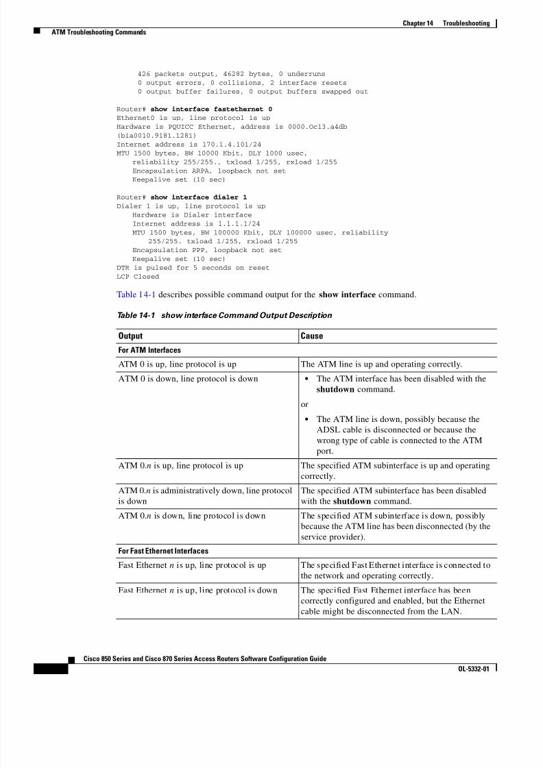
8/11/2019 Cisco 850 Series and Cisco 870 Series
http://slidepdf.com/reader/full/cisco-850-series-and-cisco-870-series 144/196
14-4Cisco 850 Series and Cisco 870 Series Access Routers Software Configuration Guide
OL-5332-01
Chapter 14 Troubleshooting ATM Troubleshooting Commands
426 packets output, 46282 bytes, 0 underruns 0 output errors, 0 collisions, 2 interface resets 0 output buffer failures, 0 output buffers swapped out
Router# show interface fastethernet 0Ethernet0 is up, line protocol is upHardware is PQUICC Ethernet, address is 0000.Oc13.a4db
(bia0010.9181.1281)Internet address is 170.1.4.101/24MTU 1500 bytes, BW 10000 Kbit, DLY 1000 usec,
reliability 255/255., txload 1/255, rxload 1/255Encapsulation ARPA, loopback not setKeepalive set (10 sec)
Router# show interface dialer 1Dialer 1 is up, line protocol is up
Hardware is Dialer interfaceInternet address is 1.1.1.1/24MTU 1500 bytes, BW 100000 Kbit, DLY 100000 usec, reliability
255/255. txload 1/255, rxload 1/255Encapsulation PPP, loopback not setKeepalive set (10 sec)
DTR is pulsed for 5 seconds on resetLCP Closed
Table 14-1 describes possible command output for the show interface command.
Table 14-1 show interface Command Output Description
Output Cause
For ATM Interfaces
ATM 0 is up, line protocol is up The ATM line is up and operating correctly.
ATM 0 is down, line protocol is down • The ATM interface has been disabled with theshutdown command.
or • The ATM line is down, possibly because the
ADSL cable is disconnected or because thewrong type of cable is connected to the ATMport.
ATM 0. n is up, line protocol is up The specified ATM subinterface is up and operatingcorrectly.
ATM 0. n is administratively down, line protocolis down
The specified ATM subinterface has been disabledwith the shutdown command.
ATM 0. n is down, line protocol is down The specified ATM subinterface is down, possiblybecause the ATM line has been disconnected (by the
service provider).For Fast Ethernet Interfaces
Fast Ethernet n is up, line protocol is up The specified Fast Ethernet interface is connected tothe network and operating correctly.
Fast Ethernet n is up, line protocol is down The specified Fast Ethernet interface has beencorrectly configured and enabled, but the Ethernetcable might be disconnected from the LAN.

8/11/2019 Cisco 850 Series and Cisco 870 Series
http://slidepdf.com/reader/full/cisco-850-series-and-cisco-870-series 145/196

8/11/2019 Cisco 850 Series and Cisco 870 Series
http://slidepdf.com/reader/full/cisco-850-series-and-cisco-870-series 146/196

8/11/2019 Cisco 850 Series and Cisco 870 Series
http://slidepdf.com/reader/full/cisco-850-series-and-cisco-870-series 147/196
14-7Cisco 850 Series and Cisco 870 Series Access Routers Software Configuration Guide
OL-5332-01
Chapter 14 Troubleshooting ATM Troubleshooting Commands
01:32:08:ATM(ATM0.2):VC(3) Bad SAP received 450001:32:10:ATM(ATM0.2):VC(3) Bad SAP received 4500
debug atm events Command
Use the debug atm events command to display events that occur on the ATM interface processor and todiagnose problems in an ATM network. This command provides an overall picture of the stability of thenetwork. The no form of this command disables debugging output.
If the interface is successfully communicating with the Digital Subscriber Line Access Multiplexer(DSLAM) at the telephone company, the modem state is 0x10. If the interface is not communicating withthe DSLAM, the modem state is 0x8. Example 14-5 shows an ADSL line that is up and trainingsuccessfully. Example 14-6 shows an ADSL line that is not communicating correctly. Note that themodem state does not transition to 0x10.
Example 14-5 Viewing ATM Interface Processor Events—Success
Router# debug atm eventsRouter#
00:02:57: DSL: Send ADSL_OPEN command.00:02:57: DSL: Using subfunction 0xA00:02:57: DSL: Using subfunction 0xA00:02:57: DSL: Sent command 0x500:02:57: DSL: Received response: 0x2600:02:57: DSL: Unexpected response 0x2600:02:57: DSL: Send ADSL_OPEN command.00:02:57: DSL: Using subfunction 0xA00:02:57: DSL: Using subfunction 0xA00:02:57: DSL: Sent command 0x500:03:00: DSL: 1: Modem state = 0x800:03:02: DSL: 2: Modem state = 0x1000:03:05: DSL: 3: Modem state = 0x1000:03:07: DSL: 4: Modem state = 0x1000:03:09: DSL: Received response: 0x2400:03:09: DSL: Showtime!00:03:09: DSL: Sent command 0x1100:03:09: DSL: Received response: 0x6100:03:09: DSL: Read firmware revision 0x1A0400:03:09: DSL: Sent command 0x3100:03:09: DSL: Received response: 0x1200:03:09: DSL: operation mode 0x000100:03:09: DSL: SM: [DMTDSL_DO_OPEN -> DMTDSL_SHOWTIME]
Example 14-6 Viewing ATM Interface Processor Events—Failure
Router# debug atm eventsRouter#00:02:57: DSL: Send ADSL_OPEN command.
00:02:57: DSL: Using subfunction 0xA00:02:57: DSL: Using subfunction 0xA00:02:57: DSL: Sent command 0x500:02:57: DSL: Received response: 0x2600:02:57: DSL: Unexpected response 0x2600:02:57: DSL: Send ADSL_OPEN command.00:02:57: DSL: Using subfunction 0xA00:02:57: DSL: Using subfunction 0xA00:02:57: DSL: Sent command 0x500:03:00: DSL: 1: Modem state = 0x800:03:00: DSL: 1: Modem state = 0x8

8/11/2019 Cisco 850 Series and Cisco 870 Series
http://slidepdf.com/reader/full/cisco-850-series-and-cisco-870-series 148/196
14-8Cisco 850 Series and Cisco 870 Series Access Routers Software Configuration Guide
OL-5332-01
Chapter 14 Troubleshooting ATM Troubleshooting Commands
00:03:00: DSL: 1: Modem state = 0x800:03:00: DSL: 1: Modem state = 0x800:03:00: DSL: 1: Modem state = 0x800:03:00: DSL: 1: Modem state = 0x8
debug atm packet CommandUse the debug atm packet command to display all process-level ATM packets for both outbound andinbound packets. The output reports information online when a packet is received or a transmission isattempted. The no form of this command disables debugging output.
Caution Because the debug atm packet command generates a significant amount of output for every packetprocessed, use it only when network traffic is low, so that other system activities are not adverselyaffected.
The command syntax is:
debug atm packet [ interface atm number [vcd vcd-number ][vc vpi/vci number ]]no debug atm packet [ interface atm number [vcd vcd-number ][vc vpi/vci number ]]
where the keywords are defined as follows:
interface atm number (Optional) ATM interface or subinterface number.
vcd vcd-number (Optional) Number of the virtual circuit designator (VCD).
vc vpi/vci number VPI/VCI value of the ATM PVC.
Example 14-7 shows sample output for the debug atm packet command.
Example 14-7 Viewing ATM Packet Processing
Router# debug atm packetRouter#01:23:48:ATM0(O):
VCD:0x1 VPI:0x1 VCI:0x64 DM:0x0 SAP :AAAA CTL:03 OUI :000000 TYPE:0800 Length:0x7001:23:48:4500 0064 0008 0000 FF01 9F80 0E00 0010 0E00 0001 0800 A103 0AF3 17F7 000001:23:48:0000 004C BA10 ABCD ABCD ABCD ABCD ABCD ABCD ABCD ABCD ABCD ABCD ABCD ABCD01:23:48:ABCD ABCD ABCD ABCD ABCD ABCD ABCD ABCD ABCD ABCD ABCD ABCD ABCD ABCD ABCD01:23:48:ABCD ABCD ABCD ABCD ABCD01:23:48:01:23:48:ATM0(I):
VCD:0x1 VPI:0x1 VCI:0x64 Type:0x0 S AP:AAAA CTL:03 O UI:000000 TYPE:0800 Length:0x7001:23:48:4500 0064 0008 0000 FE01 A080 0E00 0001 0E00 0010 0000 A903 0AF3 17F7 000001:23:48:0000 004C BA10 ABCD ABCD ABCD ABCD ABCD ABCD ABCD ABCD ABCD ABCD ABCD ABCD01:23:48:ABCD ABCD ABCD ABCD ABCD ABCD ABCD ABCD ABCD ABCD ABCD ABCD ABCD ABCD ABCD01:23:48:ABCD ABCD ABCD ABCD ABCD01:23:48:
Table 14-3 describes some of the fields shown in the debug atm packet command output.
Table 14-3 debug atm packet Command Output Description
Field Description
ATM0 Interface that is generating the packet.
(O) Output packet. (I) would mean receive packet.

8/11/2019 Cisco 850 Series and Cisco 870 Series
http://slidepdf.com/reader/full/cisco-850-series-and-cisco-870-series 149/196
14-9Cisco 850 Series and Cisco 870 Series Access Routers Software Configuration Guide
OL-5332-01
Chapter 14 Troubleshooting Software Upgrade Methods
Software Upgrade MethodsSeveral methods are available for upgrading software on the Cisco 850 and Cisco 870 series accessrouters, including:
• Copy the new software image to flash memory over the LAN or WAN while the existing Cisco IOSsoftware image is operating.
• Copy the new software image to flash memory over the LAN while the boot image (ROM monitor)is operating.
• Copy the new software image over the console port while in ROM monitor mode.
• From ROM monitor mode, boot the router from a software image that is loaded on a TFTP server.To use this method, the TFTP server must be on the same LAN as the router.
Recovering a Lost PasswordTo recover a lost enable or lost enable-secret password:
1. Change the Configuration Register
2. Reset the Router
3. Reset the Password and Save Your Changes (for lost enable secret passwords only)
4. Reset the Configuration Register Value
Note Recovering a lost password is only possible when you are connected to the router through the consoleport. These procedures cannot be performed through a Telnet session.
Tip See the “Hot Tips” section on Cisco.com for additional information on replacing enable secretpasswords.
VCD: 0x n Virtual circuit associated with this packet, where n is somevalue.
VPI: 0x n Virtual path identifier for this packet, where n is some value.DM: 0x n Descriptor mode bits, where n is some value.
Length: n Total length of the packet (in bytes) including the ATMheaders.
Table 14-3 debug atm packet Command Output Description (continued)
Field Description

8/11/2019 Cisco 850 Series and Cisco 870 Series
http://slidepdf.com/reader/full/cisco-850-series-and-cisco-870-series 150/196

8/11/2019 Cisco 850 Series and Cisco 870 Series
http://slidepdf.com/reader/full/cisco-850-series-and-cisco-870-series 151/196
14-11Cisco 850 Series and Cisco 870 Series Access Routers Software Configuration Guide
OL-5332-01
Chapter 14 Troubleshooting Recovering a Lost Password
Step 5 Using the power switch, turn off the router and then turn it back on.
Step 6 Enter the config-register 0x01 command from privileged EXEC mode To enable the break setting(indicated by the value of bit 8 in the configuration register).
• Break enabled—Bit 8 is set to 0.
• Break disabled (default setting)—Bit 8 is set to 1.
Reset the Router
To reset the router, follow these steps:
Step 1 If break is enabled, go to Step 2 . If break is disabled, turn the router off (O), wait 5 seconds, and turn iton (|) again. Within 60 seconds, press the Break key. The terminal displays the ROM monitor prompt.Go to Step 3 .
Note Some terminal keyboards have a key labeled Break . If your keyboard does not have a Break key,see the documentation that came with the terminal for instructions on how to send a break.
Step 2 Press break . The terminal displays the following prompt:
rommon 2>
Step 3 Enter confreg 0x2142 to reset the configuration register:
rommon 2> confreg 0x2142
Step 4 Initialize the router by entering the reset command:
rommon 2> reset
The router cycles its power, and the configuration register is set to 0x2142. The router uses the boot ROMsystem image, indicated by the system configuration dialog:
--- System Configuration Dialog ---
Step 5 Enter no in response to the prompts until the following message is displayed:
Press RETURN to get started!
Step 6 Press Return . The following prompt appears:
Router>
Step 7 Enter the enable command to enter enable mode. Configuration changes can be made only in enablemode:
Router> enable
The prompt changes to the privileged EXEC prompt:
Router#
Step 8 Enter the show startup-config command to display an enable password in the configuration file:
Router# show startup-config
8/11/2019 Cisco 850 Series and Cisco 870 Series
http://slidepdf.com/reader/full/cisco-850-series-and-cisco-870-series 152/196
14-12Cisco 850 Series and Cisco 870 Series Access Routers Software Configuration Guide
OL-5332-01
Chapter 14 Troubleshooting Recovering a Lost Password
If you are recovering an enable password, do not perform the steps in the following “Reset the Passwordand Save Your Changes” section. Instead, complete the password recovery process by performing thesteps in the “Reset the Configuration Register Value” section.
If you are recovering an enable secret password, it is not displayed in the show startup-config commandoutput. Complete the password recovery process by performing the steps in the following “Reset the
Password and Save Your Changes” section.
Reset the Password and Save Your ChangesTo reset your password and save the changes, follow these steps:
Step 1 Enter the configure terminal command to enter global configuration mode:
Router# configure terminal
Step 2 Enter the enable secret command to reset the enable secret password in the router:
Router(config)# enable secret password
Step 3 Enter exit to exit global configuration mode:
Router(config)# exit
Step 4 Save your configuration changes:
Router# copy running-config startup-config
Reset the Configuration Register Value
To reset the configuration register value after you have recovered or reconfigured a password, followthese steps:
Step 1 Enter the configure terminal command to enter global configuration mode:
Router# configure terminal
Step 2 Enter the configure register command and the original configuration register value that you recorded.
Router(config)# config-reg value
Step 3 Enter exit to exit configuration mode:
Router(config)# exit
Note To return to the configuration being used before you recovered the lost enable password, do notsave the configuration changes before rebooting the router.
Step 4 Reboot the router, and enter the recovered password.

8/11/2019 Cisco 850 Series and Cisco 870 Series
http://slidepdf.com/reader/full/cisco-850-series-and-cisco-870-series 153/196
14-13Cisco 850 Series and Cisco 870 Series Access Routers Software Configuration Guide
OL-5332-01
Chapter 14 Troubleshooting Managing Your Router with SDM
Managing Your Router with SDMThe Cisco SDM tool is a free software configuration utility, supporting the Cisco 850 and Cisco 870series access routers. It includes a web-based GUI that offers the following features:
• Simplified setup
• Advanced configuration
• Router security
• Router monitoring

8/11/2019 Cisco 850 Series and Cisco 870 Series
http://slidepdf.com/reader/full/cisco-850-series-and-cisco-870-series 154/196
14-14Cisco 850 Series and Cisco 870 Series Access Routers Software Configuration Guide
OL-5332-01
Chapter 14 Troubleshooting Managing Your Router with SDM

8/11/2019 Cisco 850 Series and Cisco 870 Series
http://slidepdf.com/reader/full/cisco-850-series-and-cisco-870-series 155/196

8/11/2019 Cisco 850 Series and Cisco 870 Series
http://slidepdf.com/reader/full/cisco-850-series-and-cisco-870-series 156/196

8/11/2019 Cisco 850 Series and Cisco 870 Series
http://slidepdf.com/reader/full/cisco-850-series-and-cisco-870-series 157/196
A-1Cisco 850 Series and Cisco 870 Series Access Routers Software Configuration Guide
OL-5332-01
A P P E N D I X ACisco IOS Software Basic Skills
Understanding how to use Cisco IOS software can save you time when you are configuring your router.If you need a refresher, take a few minutes to read this appendix.
This appendix contains the following sections:
• Configuring the Router from a PC
• Understanding Command Modes
• Getting Help
• Enable Secret Passwords and Enable Passwords
• Entering Global Configuration Mode
• Using Commands
• Saving Configuration Changes
• Summary
• Where to Go Next
If you are already familiar with Cisco IOS software, go to one of the following chapters:
• Chapter 1, “Basic Router Configuration”
• Chapter 2, “Sample Network Deployments”
• One of the configuration topic chapters described in Chapter 11, “Additional ConfigurationOptions.”
Configuring the Router from a PCYou can configure your router from a PC connected through the console port using terminal emulationsoftware. The PC uses this software to send commands to your router. Table A-1 lists some commontypes of this software, which are based on the type of PC you are using.

8/11/2019 Cisco 850 Series and Cisco 870 Series
http://slidepdf.com/reader/full/cisco-850-series-and-cisco-870-series 158/196
Table A-1 Terminal Emulation Software
PC Operating System Software
Windows 95, Windows 98, Windows 2000,Windows NT, Windows XP
HyperTerm (included with Windows software),ProComm Plus
Windows 3.1 Terminal (included with Windows software)
Macintosh ProComm, VersaTerm (supplied separately)
A-2Cisco 850 Series and Cisco 870 Series Access Routers Software Configuration Guide
OL-5332-01
Appendix A Cisco IOS Software Basic Skills Understanding Command Modes
You can use the terminal emulation software to change settings for the type of device that is connectedto the PC, in this case a router. Configure the software to the following standard VT-100 emulationsettings so that your PC can communicate with your router:
• 9600 baud
• 8 data bits
• No parity
• 1 stop bit
• No flow control
These settings should match the default settings of your router. To change the router baud, data bits,parity, or stop bits settings, you must reconfigure parameters in the ROM monitor. For more information,see Appendix C, “ROM Monitor.” To change the router flow control setting, use the flowcontrol lineconfiguration command.
For information on how to enter global configuration mode so that you can configure your router, seethe “Entering Global Configuration Mode” section later in this chapter.
Understanding Command ModesThis section describes the Cisco IOS command mode structure. Each command mode supports specificCisco IOS commands. For example, you can use the interface type number command only from globalconfiguration mode.
The following Cisco IOS command modes are hierarchical. When you begin a router session, you are inuser EXEC mode.
• User EXEC
• Privileged EXEC
• Global configuration
Table A-2 lists the command modes that are used in this guide, how to access each mode, the promptyou see in that mode, and how to exit to a mode or enter the next mode. Because each mode configures
different router elements, you might need to enter and exit modes frequently. You can see a list ofavailable commands for a particular mode by entering a question mark (?) at the prompt. For adescription of each command, including syntax, see the Cisco IOS Release 12.3 documentation set.

8/11/2019 Cisco 850 Series and Cisco 870 Series
http://slidepdf.com/reader/full/cisco-850-series-and-cisco-870-series 159/196
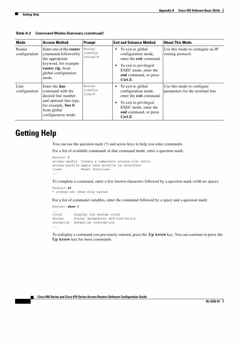
8/11/2019 Cisco 850 Series and Cisco 870 Series
http://slidepdf.com/reader/full/cisco-850-series-and-cisco-870-series 160/196
8/11/2019 Cisco 850 Series and Cisco 870 Series
http://slidepdf.com/reader/full/cisco-850-series-and-cisco-870-series 161/196
A-5Cisco 850 Series and Cisco 870 Series Access Routers Software Configuration Guide
OL-5332-01
Appendix A Cisco IOS Software Basic Skills Enable Secret Passwords and Enable Passwords
Enable Secret Passwords and Enable PasswordsBy default, the router ships without password protection. Because many privileged EXEC commands areused to set operating parameters, you should password-protect these commands to prevent unauthorizeduse.
You can use two commands to do this:
• enable secret password —A very secure, encrypted password
• enable password —A less secure, unencrypted local password
Both the enable and enable secret passwords control access to various privilege levels (0 to 15). Theenable password is intended for local use and is thus unencrypted. The enable secret password isintended for network use; that is, in environments where the password crosses the network or is storedon a TFTP server. You must enter an enable secret or enable password with a p rivilege level of 1 to gainaccess to privileged EXEC mode commands.
For maximum security, the passwords should be different. If you enter the same password for both duringthe setup process, your router accepts the passwords, but warns you that they should be different.
An enable secret password can contain from 1 to 25 uppercase and lowercase alphanumeric characters.An enable password can contain any number of uppercase and lowercase alphanumeric characters. Inboth cases, a number cannot be the first character. Spaces are also valid password characters; forexample, two words is a valid password. Leading spaces are ignored; trailing spaces are recognized.
Entering Global Configuration ModeTo make any configuration changes to your router, you must be in global configuration mode. Thissection describes how to enter global configuration mode while using a terminal or PC that is connectedto your router console port.
To enter global configuration mode, follow these steps:
Step 1 After your router boots up, enter the enable or enable secret command:
Router> enable
Step 2 If you have configured your router with an enable password, enter it when you are prompted.
The enable password does not appear on the screen when you enter it. This example shows how to enterprivileged EXEC mode:
Password: enable_password Router#
Privileged EXEC mode is indicated by the # in the prompt. You can now make changes to your routerconfiguration.
Step 3 Enter the configure terminal command to enter global configuration mode:
Router# configure terminalRouter(config)#
You can now make changes to your router configuration.

8/11/2019 Cisco 850 Series and Cisco 870 Series
http://slidepdf.com/reader/full/cisco-850-series-and-cisco-870-series 162/196
A-6Cisco 850 Series and Cisco 870 Series Access Routers Software Configuration Guide
OL-5332-01
Appendix A Cisco IOS Software Basic Skills Using Commands
Using CommandsThis section provides some tips about entering Cisco IOS commands at the command-line interface(CLI).
Abbreviating CommandsYou only have to enter enough characters for the router to recognize the command as unique. Thisexample shows how to enter the show version command:
Router # sh v
Undoing CommandsIf you want to disable a feature or undo a command you entered, you can enter the keyword no before
most commands; for example, no ip routing .
Command-Line Error MessagesTable A-3 lists some error messages that you might encounter while using the CLI to configure yourrouter.
Table A-3 Common CLI Error Messages
Error Message Meaning How to Get Help% Ambiguous command:"show con"
You did not enter enoughcharacters for your router torecognize the command.
Reenter the command, followedby a question mark ( ? ) with nospace between the command andthe question mark.
The possible keywords that youcan enter with the command aredisplayed.
% Incomplete command. You did not enter all of thekeywords or values required bythis command.
Reenter the command, followedby a question mark ( ? ) with nospace between the command andthe question mark.
The possible keywords that youcan enter with the command are
displayed.% Invalid input detected at‘^’ marker.
You entered the commandincorrectly. The error occurredwhere the caret mark (^) appears.
Enter a question mark (? ) todisplay all of the commands thatare available in this particularcommand mode.

8/11/2019 Cisco 850 Series and Cisco 870 Series
http://slidepdf.com/reader/full/cisco-850-series-and-cisco-870-series 163/196
A-7Cisco 850 Series and Cisco 870 Series Access Routers Software Configuration Guide
OL-5332-01
Appendix A Cisco IOS Software Basic Skills Saving Configuration Changes
Saving Configuration ChangesYou need to enter the copy running-config startup-config command to save your configurationchanges to nonvolatile RAM (NVRAM) so that they are not lost if there is a system reload or poweroutage. This example shows how to use this command to save your changes:
Router# copy running-config startup-configDestination filename [startup-config]?
Press Return to accept the default destination filename startup-config , or enter your desired destinationfilename and press Return .
It might take a minute or two to save the configuration to NVRAM. After the configuration has beensaved, the following message appears:
Building configuration...Router#
SummaryNow that you have reviewed some Cisco IOS software basics, you can begin to configure your router.Remember:
• You can use the question mark ( ? ) and arrow keys to help you enter commands.
• Each command mode restricts you to a set of commands. If you are having difficulty entering acommand, check the prompt, and then enter the question mark ( ? ) for a list of available commands.You might be in the wrong command mode or using the wrong syntax.
• If you want to disable a feature, enter the keyword no before the command; for example, no iprouting .
• Save your configuration changes to NVRAM so that they are not lost if there is a system reload or
power outage.
Where to Go NextTo configure your router, go to Chapter 1, “Basic Router Configuration,” and Chapter 2, “SampleNetwork Deployments.”

8/11/2019 Cisco 850 Series and Cisco 870 Series
http://slidepdf.com/reader/full/cisco-850-series-and-cisco-870-series 164/196
A-8Cisco 850 Series and Cisco 870 Series Access Routers Software Configuration Guide
OL-5332-01
Appendix A Cisco IOS Software Basic Skills Where to Go Next

8/11/2019 Cisco 850 Series and Cisco 870 Series
http://slidepdf.com/reader/full/cisco-850-series-and-cisco-870-series 165/196
B-1Cisco 850 Series and Cisco 870 Series Access Routers Software Configuration Guide
OL-5332-01
A P P E N D I X BConcepts
This appendix contains conceptual information that may be useful to Internet service providers ornetwork administrators when they configure Cisco routers. To review some typical network scenarios,see Chapter 2, “Sample Network Deployments.” For information on additional details or configurationtopics, see Chapter 11, “Additional Configuration Options.”
The following topics are included in this appendix: • ADSL
• SHDSL
• Network Protocols
• Routing Protocol Options
• PPP Authentication Protocols
• TACACS+
• Network Interfaces
• Dial Backup
• NAT • Easy IP (Phase 1)
• Easy IP (Phase 2)
• QoS
• Access Lists
ADSLADSL is a technology that allows both data and voice to be transmitted over the same line. It is apacket-based network technology that allows high-speed transmission over twisted-pair copper wire onthe local loop (“last mile”) between a network service provider (NSP) central office and the customersite, or on local loops created within either a building or a campus.
The benefit of ADSL over a serial or dialup line is that it is always on and always connected, increasingbandwidth and lowering the costs compared with a dialup or leased line. ADSL technology isasymmetric in that it allows more bandwidth from an NSP central office to the customer site than fromthe customer site to the central office. This asymmetry, combined with always-on access (whicheliminates call setup), makes ADSL ideal for Internet and intranet surfing, video on demand, and remoteLAN access.

8/11/2019 Cisco 850 Series and Cisco 870 Series
http://slidepdf.com/reader/full/cisco-850-series-and-cisco-870-series 166/196
B-2Cisco 850 Series and Cisco 870 Series Access Routers Software Configuration Guide
OL-5332-01
Appendix B Concepts SHDSL
SHDSLSHDSL is a technology based on the G.SHDSL (G.991.2) standard that allows both data and voice to betransmitted over the same line. SHDSL is a packet-based network technology that allows high-speedtransmission over twisted-pair copper wire between a network service provider (NSP) central office and
a customer site, or on local loops created within either a building or a campus.G.SHDSL devices can extend the reach from central offices and remote terminals to approximately26,000 feet (7925 m), at symmetrical data rates from 72 kbps up to 2.3 Mbps. In addition, it is repeatableat lower speeds, which means there is virtually no limit to its reach.
SHDSL technology is symmetric in that it allows equal bandwidth between an NSP central office and acustomer site. This symmetry, combined with always-on access (which eliminates call setup), makesSHDSL ideal for LAN access.
Network ProtocolsNetwork protocols enable the network to pass data from its source to a specific destination over LAN orWAN links. Routing address tables are included in the network protocols to provide the best path formoving the data through the network.
IPThe best-known Transmission Control Protocol/Internet Protocol (TCP/IP) at the internetwork layer isIP, which provides the basic packet delivery service for all TCP/IP networks. In addition to the physicalnode addresses, the IP protocol implements a system of logical host addresses called IP addresses. TheIP addresses are used by the internetwork and higher layers to identify devices and to performinternetwork routing. The Address Resolution Protocol (ARP) enables IP to identify the physical addressthat matches a given IP address.
IP is used by all protocols in the layers above and below it to deliver data, which means that all TCP/IPdata flows through IP when it is sent and received regardless of its final destination.
IP is a connectionless protocol, which means that IP does not exchange control information (called ahandshake ) to establish an end-to-end connection before transmitting data. In contrast, aconnection-oriented protocol exchanges control information with the remote computer to verify that itis ready to receive data before sending it. When the handshaking is successful, the computers haveestablished a connection. IP relies on protocols in other layers to establish the connection ifconnection-oriented services are required.
Internet Packet Exchange (IPX) exchanges routing information using Routing Information Protocol(RIP), a dynamic distance-vector routing protocol. RIP is described in more detail in the followingsubsections.
Routing Protocol OptionsRouting protocols include the following:
• Routing Information Protocol (RIP)
• Enhanced Interior Gateway Routing Protocol (Enhanced IGRP)

8/11/2019 Cisco 850 Series and Cisco 870 Series
http://slidepdf.com/reader/full/cisco-850-series-and-cisco-870-series 167/196
B-3Cisco 850 Series and Cisco 870 Series Access Routers Software Configuration Guide
OL-5332-01
Appendix B Concepts PPP Authentication Protocols
RIP and Enhanced IGRP differ in several ways, as shown in Table B-1 .
Table B-1 RIP and Enhanced IGRP Comparison
Protocol Ideal Topology Metric Routing Updates
RIP Suited for topologies with15 or fewer hops. Hop count. Maximum hopcount is 15. Best route is onewith lowest hop count.
By default, every 30 seconds.You can reconfigure this valueand also use triggeredextensions to RIP.
EnhancedIGRP
Suited for large topologieswith 16 or more hops toreach a destination.
Distance information. Basedon a successor, which is aneighboring router that has aleast-cost path to adestination that isguaranteed to not be part ofa routing loop.
Hello packets sent every5 seconds, as well asincremental updates sentwhen the state of a destinationchanges.
RIPRIP is an associated protocol for IP, and is widely used for routing protocol traffic over the Internet. RIPis a distance-vector routing protocol, which means that it uses distance (hop count) as its metric for routeselection. Hop count is the number of routers that a packet must traverse to reach its destination. Forexample, if a particular route has a hop count of 2, then a packet must traverse two routers to reach itsdestination.
By default, RIP routing updates are broadcast every 30 seconds. You can reconfigure the interval atwhich the routing updates are broadcast. You can also configure triggered extensions to RIP so thatrouting updates are sent only when the routing database is updated. For more information on triggeredextensions to RIP, see the Cisco IOS Release 12.3 documentation set.
Enhanced IGRPEnhanced IGRP is an advanced Cisco proprietary distance-vector and link state routing protocol, whichmeans it uses a metric more sophisticated than distance (hop count) for route selection. Enhanced IGRPuses a metric based on a successor, which is a neighboring router that has a least-cost path to adestination that is guaranteed not to be part of a routing loop. If a successor for a particular destinationdoes not exist but neighbors advertise the destination, the router must recompute a route.
Each router running Enhanced IGRP sends hello packets every 5 seconds to inform neighboring routersthat it is functioning. If a particular router does not send a hello packet within a prescribed period,Enhanced IGRP assumes that the state of a destination has changed and sends an incremental update.
Because Enhanced IGRP supports IP, you can use one routing protocol for multiprotocol networkenvironments, minimizing the size of the routing tables and the amount of routing information.
PPP Authentication ProtocolsThe Point-to-Point Protocol (PPP) encapsulates network layer protocol information overpoint-to-point links.

8/11/2019 Cisco 850 Series and Cisco 870 Series
http://slidepdf.com/reader/full/cisco-850-series-and-cisco-870-series 168/196
B-4Cisco 850 Series and Cisco 870 Series Access Routers Software Configuration Guide
OL-5332-01
Appendix B Concepts PPP Authentication Protocols
PPP originally emerged as an encapsulation protocol for transporting IP traffic over point-to-point links.PPP also established a standard for the assignment and management of IP addresses, asynchronous(start/stop) and bit-oriented synchronous encapsulation, network protocol multiplexing, linkconfiguration, link quality testing, error detection, and option negotiation for such capabilities asnetwork-layer address negotiation and data-compression negotiation. PPP supports these functions byproviding an extensible Link Control Protocol (LCP) and a family of Network Control Protocols (NCPs)to negotiate optional configuration parameters and facilities.
The current implementation of PPP supports two security authentication protocols to authenticate a PPPsession:
• Password Authentication Protocol (PAP)
• Challenge Handshake Authentication Protocol (CHAP)
PPP with PAP or CHAP authentication is often used to inform the central site which remote routers areconnected to it.
PAPPAP uses a two-way handshake to verify the passwords between routers. To illustrate how PAP works,imagine a network topology in which a remote office Cisco router is connected to a corporate officeCisco router. After the PPP link is established, the remote office router repeatedly sends a configuredusername and password until the corporate office router accepts the authentication.
PAP has the following characteristics:
• The password portion of the authentication is sent across the link in clear text (not scrambled orencrypted).
• PAP provides no protection from playback or repeated trial-and-error attacks.
• The remote office router controls the frequency and timing of the authentication attempts.
CHAPCHAP uses a three-way handshake to verify passwords. To illustrate how CHAP works, imagine anetwork topology in which a remote office Cisco router is connected to a corporate office Cisco router.
After the PPP link is established, the corporate office router sends a challenge message to the remoteoffice router. The remote office router responds with a variable value. The corporate office router checksthe response against its own calculation of the value. If the values match, the corporate office routeraccepts the authentication. The authentication process can be repeated any time after the link isestablished.
CHAP has the following characteristics:
• The authentication process uses a variable challenge value rather than a password.
• CHAP protects against playback attack through the use of the variable challenge value, which isunique and unpredictable. Repeated challenges limit the time of exposure to any single attack.
• The corporate office router controls the frequency and timing of the authentication attempts.
Note We recommend using CHAP because it is the more secure of the two protocols.

8/11/2019 Cisco 850 Series and Cisco 870 Series
http://slidepdf.com/reader/full/cisco-850-series-and-cisco-870-series 169/196
B-5Cisco 850 Series and Cisco 870 Series Access Routers Software Configuration Guide
OL-5332-01
Appendix B Concepts TACACS+
TACACS+Cisco 850 and Cisco 870 series routers support the Terminal Access Controller Access ControlSystem Plus (TACACS+) protocol through Telnet. TACACS+ is a Cisco proprietary authenticationprotocol that provides remote access authentication and related network security services, such as event
logging. User passwords are administered in a central database rather than in individual routers.TACACS+ also provides support for separate modular authentication, authorization, and accounting(AAA) facilities that are configured at individual routers.
Network InterfacesThis section describes the network interface protocols that Cisco 850 and Cisco 870 series routerssupport. The following network interface protocols are supported:
• Ethernet
• ATM for DSL
EthernetEthernet is a baseband LAN protocol that transports data and voice packets to the WAN interface usingcarrier sense multiple access collision detect (CSMA/CD). The term is now often used to refer to allCSMA/CD LANs. Ethernet was designed to serve in networks with sporadic, occasionally heavy trafficrequirements, and the IEEE 802.3 specification was developed in 1980 based on the original Ethernettechnology.
Under the Ethernet CSMA/CD media-access process, any host on a CSMA/CD LAN can access thenetwork at any time. Before sending data, CSMA/CD hosts listen for traffic on the network. A hostwanting to send data waits until it detects no traffic before it transmits. Ethernet allows any host on the
network to transmit whenever the network is quiet. A collision occurs when two hosts listen for traffic,hear none, and then transmit simultaneously. In this situation, both transmissions are damaged, and thehosts must retransmit at some later time. Algorithms determine when the colliding hosts shouldretransmit.
ATM for DSLAsynchronous Transfer Mode (ATM) is a high-speed multiplexing and switching protocol that supportsmultiple traffic types, including voice, data, video, and imaging.
ATM is composed of fixed-length cells that switch and multiplex all information for the network. AnATM connection is simply used to transfer bits of in formation to a destination router or host. The ATMnetwork is considered a LAN with high bandwidth availability. Unlike a LAN, which is connectionless,ATM requires certain features to provide a LAN environment to the users.
Each ATM node must establish a separate connection to every node in the ATM network that it needs tocommunicate with. All such connections are established through a permanent virtual circuit (PVC).
8/11/2019 Cisco 850 Series and Cisco 870 Series
http://slidepdf.com/reader/full/cisco-850-series-and-cisco-870-series 170/196
B-6Cisco 850 Series and Cisco 870 Series Access Routers Software Configuration Guide
OL-5332-01
Appendix B Concepts Dial Backup
PVC
A PVC is a connection between remote hosts and routers. A PVC is established for each ATM end nodewith which the router communicates. The characteristics of the PVC that are established when it iscreated are set by the ATM adaptation layer (AAL) and the encapsulation type. An AAL defines theconversion of user information into cells. An AAL segments upper-layer information into cells at thetransmitter and reassembles the cells at the receiver.
Cisco routers support the AAL5 format, which provides a streamlined data transport service thatfunctions with less overhead and affords better error detection and correction capabilities than AAL3/4.AAL5 is typically associated with variable bit rate (VBR) traffic and unspecified bit rate (UBR) traffic.
ATM encapsulation is the wrapping of data in a particular protocol header. The type of router that youare connecting to determines the type of ATM PVC encapsulation.
The routers support the following encapsulation types for ATM PVCs:
• LLC/SNAP (RFC 1483)
• VC-MUX (RFC 1483)
• PPP (RFC 2364)
Each PVC is considered a complete and separate link to a destination node. Users can encapsulate dataas needed across the connection. The ATM network disregards the contents of the data. The onlyrequirement is that data be sent to the ATM subsystem of the router in a manner that follows the specificAAL format.
Dialer InterfaceA dialer interface assigns PPP features (such as authentication and IP address assignment method) to aPVC. Dialer interfaces are used when configuring PPP over ATM.
Dialer interfaces can be configured independently of any physical interface and applied dynamically asneeded.
Dial BackupDial backup provides protection against WAN downtime by allowing a user to configure a backupmodem line connection. The following can be used to bring up the dial backup feature in Cisco IOSsoftware:
• Backup Interface
• Floating Static Routes
• Dialer Watch
Backup InterfaceA backup interface is an interface that stays idle until certain circumstances occur, such as WANdowntime, at which point it is activated. The backup interface can be a physical interface such as a BasicRate Interface (BRI), or an assigned backup dialer interface to be used in a dialer pool. While the primary
8/11/2019 Cisco 850 Series and Cisco 870 Series
http://slidepdf.com/reader/full/cisco-850-series-and-cisco-870-series 171/196
B-7Cisco 850 Series and Cisco 870 Series Access Routers Software Configuration Guide
OL-5332-01
Appendix B Concepts NAT
line is up, the backup interface is placed in standby mode. In standby mode, the backup interface iseffectively shut down until it is enabled. Any route associated with the backup interface does not appearin the routing table.
Because the backup interface command is dependent on the router’s identifying that an interface isphysically down, it is commonly used to back up ISDN BRI connections, asynchronous lines, and leased
lines. The interfaces to such connections go down when the primary line fails, and the backup interfacequickly identifies such failures.
Floating Static RoutesFloating static routes are static routes that have an administrative distance greater than the administrativedistance of dynamic routes. Administrative distances can be configured on a static route so that the staticroute is less desirable than a dynamic route. In this manner, the static route is not used when the dynamicroute is available. However, if the dynamic route is lost, the static route can take over, and the traffic canbe sent through this alternative route. If this alternative route uses a dial-on-demand routing (DDR)interface, then that interface can be used as a backup feature.
Dialer WatchDialer watch is a backup feature that integrates dial backup with routing capabilities. Dialer watchprovides reliable connectivity without having to define traffic of interest to trigger outgoing calls at thecentral router. Hence, dialer watch can be considered regular DDR with no requirement for traffic ofinterest. By configuring a set of watched routes that define the primary interface, you are able to monitorand track the status of the primary interface as watched routes are added and deleted.
When a watched route is deleted, dialer watch checks for at least one valid route for any of the IPaddresses or networks being watched. If there is no valid route, the primary line is considered down andunusable. If there is a valid route for at least one of the watched IP networks defined and the route ispointing to an interface other than the backup interface configured for dialer watch, the primary link isconsidered up and dialer watch does not initiate the backup link.
NATNetwork Address Translation (NAT) provides a mechanism for a privately addressed network to accessregistered networks, such as the Internet, without requiring a registered subnet address. This mechanismeliminates the need for host renumbering and allows the same IP address range to be used in multipleintranets.
NAT is configured on the router at the border of an inside network (a network that uses nonregistered IPaddresses) and an outside network (a network that uses a globally unique IP address; in this case, theInternet). NAT translates the inside local addresses (the nonregistered IP addresses assigned to hosts onthe inside network) into globally unique IP addresses before sending packets to the outside network.
With NAT, the inside network continues to use its existing private or obsolete addresses. These addressesare converted into legal addresses before packets are forwarded onto the outside network. The translationfunction is compatible with standard routing; the feature is required only on the router connecting theinside network to the outside domain.

8/11/2019 Cisco 850 Series and Cisco 870 Series
http://slidepdf.com/reader/full/cisco-850-series-and-cisco-870-series 172/196
B-8Cisco 850 Series and Cisco 870 Series Access Routers Software Configuration Guide
OL-5332-01
Appendix B Concepts Easy IP (Phase 1)
Translations can be static or dynamic. A static address translation establishes a one-to-one mappingbetween the inside network and the outside domain. Dynamic address translations are defined bydescribing the local addresses to be translated and the pool of addresses from which to allocate outsideaddresses. Allocation occurs in numeric order, and multiple pools of contiguous address blocks can bedefined.
NAT eliminates the need to readdress all hosts that require external access, saving time and money. Italso conserves addresses through application port-level multiplexing. With NAT, internal hosts can sharea single registered IP address for all external communications. In this type of configuration, relativelyfew external addresses are required to support many internal hosts, thus conserving IP addresses.
Because the addressing scheme on the inside network may conflict with registered addresses alreadyassigned within the Internet, NAT can support a separate address pool for overlapping networks andtranslate as appropriate.
Easy IP (Phase 1)The Easy IP (Phase 1) feature combines Network Address Translation (NAT) and PPP/Internet Protocol
Control Protocol (IPCP). This feature enables a Cisco router to automatically negotiate its ownregistered WAN interface IP address from a central server and to enable all remote hosts to access theInternet using this single registered IP address. Because Easy IP (Phase 1) uses existing port-levelmultiplexed NAT functionality within Cisco IOS software, IP addresses on the remote LAN are invisibleto the Internet.
The Easy IP (Phase 1) fea ture combines NAT and PPP/IPCP. With NAT, the router translates thenonregistered IP addresses used by the LAN devices into the globally unique IP address used by thedialer interface. The ability of multiple LAN devices to use the same globally unique IP address is knownas overloading . NAT is configured on the router at the border of an inside network (a network that usesnonregistered IP addresses) and an outside network (a network that uses a globally unique IP address; inthis case, the Internet).
With PPP/IPCP, Cisco routers automatically negotiate a globally unique (registered) IP address for thedialer interface from the ISP router.
Easy IP (Phase 2)The Easy IP (Phase 2) feature combines Dynamic Host Configuration Protocol (DHCP) server and relay.DHCP is a client-server protocol that enables devices on an IP network (the DHCP clients) to requestconfiguration information from a DHCP server. DHCP allocates network addresses from a central poolon an as-needed basis. DHCP is useful for assigning IP addresses to hosts connected to the networktemporarily or for sharing a limited pool of IP addresses among a group of hosts that do not needpermanent IP addresses.
DHCP frees you from having to assign an IP address to each client manually.
DHCP configures the router to forward UDP broadcasts, including IP address requests, from DHCPclients. DHCP allows for increased automation and fewer network administration problems by:
• Eliminating the need for the manual configuration of individual computers, printers , and shared filesystems
• Preventing the simultaneous use of the same IP address by two clients
• Allowing configuration from a central site

8/11/2019 Cisco 850 Series and Cisco 870 Series
http://slidepdf.com/reader/full/cisco-850-series-and-cisco-870-series 173/196
B-9Cisco 850 Series and Cisco 870 Series Access Routers Software Configuration Guide
OL-5332-01
Appendix B Concepts QoS
QoSThis section describes Quality of Service (QoS) parameters, including the following:
• IP Precedence
• PPP Fragmentation and Interleaving • CBWFQ
• RSVP
• Low Latency Queuing
QoS refers to the capability of a network to provide better service to selected network traffic over varioustechnologies, including ATM, Ethernet and IEEE 802.1 networks, and IP-routed networks that may useany or all of these underlying technologies. Primary goals of QoS include dedicated bandwidth,controlled jitter and latency (required by some real-time and interactive traffic), and improved losscharacteristics. QoS technologies provide the elemental building blocks for future business applicationsin campus, WAN, and service provider networks.
QoS must be configured throughout your network, no t just on your router running VoIP, to improve voice
network performance. Not all QoS techniques are appropriate for all network routers. Edge routers andbackbone routers in your network do not necessarily perform the same operations; the QoS tasks theyperform might differ as well. To configure your IP network for real-time voice traffic, you need toconsider the functions of both edge and backbone routers in your network.
QoS software enables complex networks to control and predictably service a variety of networkedapplications and traffic types. Almost any network can take advantage of QoS for optimum efficiency,whether it is a small corporate network, an Internet service provider, or an enterprise network.
IP PrecedenceYou can partition traffic in up to six classes of serv ice using IP Precedence (two others are reserved for
internal network use). The queuing technologies throughout the network can then use this signal toexpedite handling.
Features such as policy-based routing and committed access rate (CAR) can be used to set precedencebased on extended access-list classification. This allows considerable flexibility for precedenceassignment, including assignment by application or user, by destination and source subnet, and so on.Typically this functionality is deployed as close to the edge of the network (or administrative domain)as possible, so that each subsequent ne twork element can provide service based on the determined policy.
IP Precedence can also be set in the host or network client with the signaling used optionally. IPPrecedence enables service classes to be established using existing network queuing mechanisms (suchas class-based weighted fair queueing [CBWFQ]) with no changes to existing applications orcomplicated network requirements.
PPP Fragmentation and InterleavingWith multiclass multilink PPP interleaving, large packets can be multilink-encapsulated and fragmentedinto smaller packets to satisfy the delay requirements of real-time voice traffic; small real-time packets,which are not multilink encapsulated, are transmitted between fragments of the large packets. Theinterleaving feature also provides a special transmit queue for the smaller, delay-sensitive packets,enabling them to be transmitted earlier than other flows. Interleaving provides the delay bounds fordelay-sensitive voice packets on a slow link that is used for other best-effort traffic.

8/11/2019 Cisco 850 Series and Cisco 870 Series
http://slidepdf.com/reader/full/cisco-850-series-and-cisco-870-series 174/196
B-10Cisco 850 Series and Cisco 870 Series Access Routers Software Configuration Guide
OL-5332-01
Appendix B Concepts QoS
In general, multilink PPP with interleaving is used in conjunction with CBWFQ and RSVP or IPPrecedence to ensure voice packet delivery. Use multilink PPP with interleaving and CBWFQ to definehow data is managed; use Resource Reservation Protocol (RSVP) or IP Precedence to give priority tovoice packets.
CBWFQIn general, class-based weighted fair queuing (CBWFQ) is used in conjunction with multilink PPP andinterleaving and RSVP or IP Precedence to ensure voice packet delivery. CBWFQ is used with multilinkPPP to define how data is managed; RSVP or IP Precedence is used to give priority to voice packets.
There are two levels of queueing; ATM queues and Cisco IOS queues. CBWFQ is applied to Cisco IOSqueues. A first-in-first-out (FIFO) Cisco IOS queue is automatically created when a PVC is created. Ifyou use CBWFQ to create classes and attach them to a PVC, a queue is created for each class.
CBWFQ ensures that queues have sufficient bandwidth and that traffic gets predictable service.Low-volume traffic streams are preferred; high-volume traffic streams share the remaining capacity,obtaining equal or proportional bandwidth.
RSVPRSVP enables routers to reserve enough bandwidth on an interface to ensure reliability and qualityperformance. RSVP allows end systems to request a particular QoS from the network. Real-time voicetraffic requires network consistency. Without consistent QoS, real-time traffic can experience jitter,insufficient bandwidth, delay variations, or information loss. RSVP works in conjunction with currentqueuing mechanisms. It is up to the interface queuing mechanism (such as CBWFQ) to implement thereservation.
RSVP works well on PPP, HDLC, and similar serial-line interfaces. It does not work well onmulti-access LANs. RSVP can be equated to a dynamic access list for packet flows.
You should configure RSVP to ensure QoS if the following conditions describe your network: • Small-scale voice network implementation
• Links slower than 2 Mbps
• Links with high utilization
• Need for the best possible voice quality
Low Latency QueuingLow latency queuing (LLQ) provides a low-latency strict priority transmit queue for real-time traffic.Strict priority queuing allows delay-sensitive data to be dequeued and sent first (before packets in otherqueues are dequeued), giving delay-sensitive data preferential treatment over other traffic.

8/11/2019 Cisco 850 Series and Cisco 870 Series
http://slidepdf.com/reader/full/cisco-850-series-and-cisco-870-series 175/196
B-11Cisco 850 Series and Cisco 870 Series Access Routers Software Configuration Guide
OL-5332-01
Appendix B Concepts Access Lists
Access ListsWith basic standard and static extended access lists, you can approximate session filtering by using theestablished keyword with the permit command. The established keyword filters TCP packets based onwhether the ACK or RST bits are set. (Set ACK or RST bits ind icate that the packet is not the first in the
session and the packet therefore belongs to an established session.) This filter criterion would be part ofan access list applied permanently to an interface.

8/11/2019 Cisco 850 Series and Cisco 870 Series
http://slidepdf.com/reader/full/cisco-850-series-and-cisco-870-series 176/196

8/11/2019 Cisco 850 Series and Cisco 870 Series
http://slidepdf.com/reader/full/cisco-850-series-and-cisco-870-series 177/196
C-1Cisco 850 Series and Cisco 870 Series Access Routers Software Configuration Guide
OL-5332-01
A P P E N D I X CROM Monitor
The ROM monitor firmware runs when the router is powered up or reset. The firmware helps to initializethe processor hardware and boot the operating system software. You can use the ROM monitor toperform certain configuration tasks, such as recovering a lost password or downloading software overthe console port. If there is no Cisco IOS software image loaded on the router, the ROM monitor runsthe router.
This appendix contains the following sections:
• Entering the ROM Monitor
• ROM Monitor Commands
• Command Descriptions
• Disaster Recovery with TFTP Download
• Configuration Register
• Console Download
• Debug Commands
• Exiting the ROM Monitor
Entering the ROM MonitorTo use the ROM monitor, you must be using a terminal or PC that is connected to the router over theconsole port.
Perform these steps to configure the router to boot up in ROM monitor mode the next time it is rebooted.
Command Purpose
Step 1 enable Enters privileged EXEC mode.
Enter your password if prompted.Step 2 configure terminal Enters global configuration mode.
Step 3 config-reg 0x0 Resets the configuration register.

8/11/2019 Cisco 850 Series and Cisco 870 Series
http://slidepdf.com/reader/full/cisco-850-series-and-cisco-870-series 178/196
C-2Cisco 850 Series and Cisco 870 Series Access Routers Software Configuration Guide
OL-5332-01
Appendix C ROM Monitor ROM Monitor Commands
Timesaver Break (system interrupt) is always enabled for 60 seconds after the router reboots, regardless of whetherit is set to on or off in the configuration register. During this 60-second window, you can break to theROM monitor prompt by pressing the Break key.
ROM Monitor CommandsEnter ? or help at the ROM monitor prompt to display a list of available commands and options, asfollows:
rommon 1 > ?
alias set and display aliases commandboot boot up an external processbreak set/show/clear the breakpointconfreg configuration register utilitycont continue executing a downloaded imagecontext display the context of a loaded imagecookie display contents of cookie PROM in hex
copy Copy a file-copy [-b <buffer_size>] <src_file> <dst_file>delete Delete file(s)-delete <filenames ...>dir List files in directories-dir <directory>dis display instruction stream dnld serial download a program moduleformat Format a filesystem-format <filessystem>frame print out a selected stack framefsck Check filesystem consistency-fsck <filesystem>help monitor builtin command helphistory monitor command history
meminfo main memory infor mation mkdir Create dir(s)-mkd ir <dirnames ... > more Concatenate (type ) file(s)-cat <f ilenames ...>
rename Rename a file-rename <old_name> <new_name>repeat repeat a monitor commandreset system resetrmdir Remove a directoryset display the monitor variablesstack produce a stack tracesync write monitor environment to NVRAMsysret print out info from last system returntftpdnld tftp image downloadunalias unset an aliasunset unset a monitor variablexmodem x/ymodem image download
Step 4 exit Exits global configuration mode.
Step 5 reload Reboots the router with the new configuration register value. The routerremains in ROM monitor and does not boot the Cisco IOS software.
As long as the configuration value is 0x0, you must manually boot theoperating system from the console. See the boot command in the “ CommandDescriptions ” section in this appendix.
After the router reboots, it is in ROM monitor mode. The number in theprompt increments with each new line.
Command Purpose

8/11/2019 Cisco 850 Series and Cisco 870 Series
http://slidepdf.com/reader/full/cisco-850-series-and-cisco-870-series 179/196

8/11/2019 Cisco 850 Series and Cisco 870 Series
http://slidepdf.com/reader/full/cisco-850-series-and-cisco-870-series 180/196
C-4Cisco 850 Series and Cisco 870 Series Access Routers Software Configuration Guide
OL-5332-01
Appendix C ROM Monitor Disaster Recovery with TFTP Download
TFTP Download Command VariablesThis section describes the system variables that can be set in ROM monitor mode and that are usedduring the TFTP download process. There are both required variables and optional variables.
Note The commands described in this section are case sensitive and must be entered exactly as shown.
Required Variables
These variables must be set with these commands before you use the tftpdnld command:
Variable Command
IP address of the router. IP_ADDRESS= ip_address
Subnet mask of the router. IP_SUBNET_MASK= ip_address
IP address of the default gateway of therouter.
DEFAULT_GATEWAY= ip_address
IP address of the TFTP server from which thesoftware will be downloaded.
TFTP_SERVER= ip_address
Name of the file that will be downloaded tothe router.
TFTP_FILE= filename
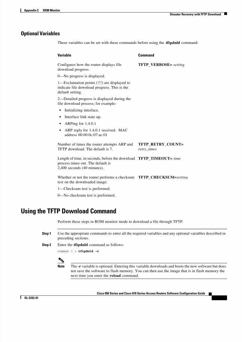
8/11/2019 Cisco 850 Series and Cisco 870 Series
http://slidepdf.com/reader/full/cisco-850-series-and-cisco-870-series 181/196
C-5Cisco 850 Series and Cisco 870 Series Access Routers Software Configuration Guide
OL-5332-01
Appendix C ROM Monitor Disaster Recovery with TFTP Download
Optional Variables
These variables can be set with these commands before using the tftpdnld command:
Variable Command
Configures how the router displays filedownload progress.
0—No progress is displayed.
1—Exclamation points (!!!) are displayed toindicate file download progress. This is thedefault setting.
2—Detailed progress is displayed during thefile download process; for example:
• Initializing interface.
• Interface link state up.
• ARPing for 1.4.0.1
• ARP reply for 1.4.0.1 received. MACaddress 00:00:0c:07:ac:01
TFTP_VERBOSE= setting
Number of times the router attempts ARP andTFTP download. The default is 7.
TFTP_RETRY_COUNT= retry_times
Length of time, in seconds, before the downloadprocess times out. The default is2,400 seconds (40 minutes).
TFTP_TIMEOUT= time
Whether or not the router performs a checksumtest on the downloaded image:
1—Checksum test is performed.
0—No checksum test is performed.
TFTP_CHECKSUM= setting
Using the TFTP Download CommandPerform these steps in ROM monitor mode to download a file through TFTP.
Step 1 Use the appropriate commands to enter all the required variables and any optional variables described in
preceding sections.Step 2 Enter the tftpdnld command as follows:
rommon 1 > tftpdnld -r
Note The -r variable is optional. Entering this variable downloads and boots the new software but doesnot save the software to flash memory. You can then use the image that is in flash memory thenext time you enter the reload command.

8/11/2019 Cisco 850 Series and Cisco 870 Series
http://slidepdf.com/reader/full/cisco-850-series-and-cisco-870-series 182/196
C-6Cisco 850 Series and Cisco 870 Series Access Routers Software Configuration Guide
OL-5332-01
Appendix C ROM Monitor Configuration Register
You will see output similar to the following:
IP_ADDRESS: 10.3.6.7IP_SUBNET_MASK: 255.255.0.0DEFAULT_GATEWAY: 10.3.0.1TFTP_SERVER: 192.168.254.254TFTP_FILE: c870-advsecurityk9-mz
Do you wish to continue? y/n: [n]:
Step 3 If you are sure that you want to continue, enter y in response to the question in the output:
Do you wish to continue? y/n: [n]: y
The router begins to download the new file.
If you mistakenly entered yes, you can enter Ctrl-C or Break to stop the transfer before the flashmemory is erased.
Configuration RegisterThe virtual configuration register is in nonvolatile RAM (NVRAM) and has the same functionality asother Cisco routers. You can view or modify the virtual configuration register from either the ROMmonitor or the operating system software. Within the ROM monitor, you can change the configurationregister by entering the register value in hexadecimal format, or by allowing the ROM monitor to promptyou for the setting of each bit.
Changing the Configuration Register ManuallyTo change the virtual configuration register from the ROM monitor manually, enter the confreg command followed by the new value of the register in hexadecimal format, as shown in the followingexample:rommon 1 > confreg 0x2101
You must reset or power cycle for new config to take effectrommon 2 >
The value is always interpreted as hexadecimal. The new virtual configuration register value is writteninto NVRAM but does not take effect until you reset or reboot the router.
Changing the Configuration Register Using PromptsEntering the confreg command without an argument displays the contents of the virtual configurationregister and a prompt to alter the contents by describing the meaning of each bit.
In either case, the new virtual configuration register value is written into NVRAM but does not takeeffect until you reset or reboot the router.

8/11/2019 Cisco 850 Series and Cisco 870 Series
http://slidepdf.com/reader/full/cisco-850-series-and-cisco-870-series 183/196

8/11/2019 Cisco 850 Series and Cisco 870 Series
http://slidepdf.com/reader/full/cisco-850-series-and-cisco-870-series 184/196
C-8Cisco 850 Series and Cisco 870 Series Access Routers Software Configuration Guide
OL-5332-01
Appendix C ROM Monitor Debug Commands
Command DescriptionThe following are the syntax and descriptions for the xmodem console download command:
xmodem [-cyrx] destination_file_name
c Optional. Performs the download using 16-bit cyclic redundancy check (CRC-16) errorchecking to validate packets. Default is 8-bit CRC.
y Optional. Sets the router to perform the download using Ymodem protocol. The defaultis Xmodem protocol. The protocols differ as follows:
• Xmodem supports a 128-block transfer size. Ymodem supports a 1024-blocktransfer size.
• Ymodem uses CRC-16 error checking to validate each packet. Depending on thedevice that the software is being downloaded from, this function might not besupported by Xmodem.
r Optional. Image is loaded into DRAM for execution. The default is to load the image
into flash memory.x Optional. Image is loaded into DRAM without being executed.
destination_ file_name
Name of the system image file or the system configuration file. In order for the routerto recognize it, the name of the configuration file must be router_confg .
Follow these steps to run Xmodem:
Step 1 Move the image file to the local drive where Xmodem will execute.
Step 2 Enter the xmodem command.
Error ReportingBecause the ROM monitor console download uses the console to perform the data transfer, when an erroroccurs during a data transfer, error messages are only displayed on the console once the data transfer isterminated.
If you have changed the baud rate from the default rate, the error message is followed by a messagetelling you to restore the terminal to the baud rate specified in the configuration register.
Debug CommandsMost ROM monitor debugging commands are functional only when Cisco IOS software has crashed oris halted. If you enter a debugging command and Cisco IOS crash information is not available, you seethe following error message:
"xxx: kernel context state is invalid, can not proceed."

8/11/2019 Cisco 850 Series and Cisco 870 Series
http://slidepdf.com/reader/full/cisco-850-series-and-cisco-870-series 185/196
C-9Cisco 850 Series and Cisco 870 Series Access Routers Software Configuration Guide
OL-5332-01
Appendix C ROM Monitor Debug Commands
The following are ROM monitor debugging commands:
• stack or k —Produces a stack trace; for example:
rommon 6> stackStack trace:PC = 0x801111b0Frame 00: FP = 0x80005ea8 PC = 0x801111b0Frame 01: FP = 0x80005eb4 PC = 0x80113694Frame 02: FP = 0x80005f74 PC = 0x8010eb44Frame 03: FP = 0x80005f9c PC = 0x80008118Frame 04: FP = 0x80005fac PC = 0x80008064Frame 05: FP = 0x80005fc4 PC = 0xfff03d70
• context —Displays processor context; for example:
rommon 7> contextCPU context of the most recent exception:PC = 0x801111b0 MSR = 0x00009032 CR = 0x53000035 LR = 0x80113694CTR = 0x801065e4 XER = 0xa0006d36 DAR = 0xffffffff DSISR = 0xffffffffDEC = 0xffffffff TBU = 0xffffffff TBL = 0xffffffff IMMR = 0xffffffffR0 = 0x00000000 R1 = 0x80005ea8 R2 = 0xffffffff R3 = 0x00000000R4 = 0x8fab0d76 R5 = 0x80657d00 R6 = 0x80570000 R7 = 0x80570000
R8 = 0x00000000 R9 = 0x80570000 R10 = 0x0000954c R11 = 0x00000000R12 = 0x00000080 R13 = 0xffffffff R14 = 0xffffffff R15 = 0xffffffffR16 = 0xffffffff R17 = 0xffffffff R18 = 0xffffffff R19 = 0xffffffffR20 = 0xffffffff R21 = 0xffffffff R22 = 0xffffffff R23 = 0xffffffffR24 = 0xffffffff R25 = 0xffffffff R26 = 0xffffffff R27 = 0xffffffffR28 = 0xffffffff R29 = 0xffffffff R30 = 0xffffffff R31 = 0xffffffff
• frame —Displays an individual stack frame.
• sysret —Displays return information from the last booted system image. This information includesthe reason for terminating the image, a stack dump of up to eight frames, and, if an exception isinvolved, the address where the exception occurred; for example:
rommon 8> sysretSystem Return Info:count: 19, reason: user breakpc:0x801111b0, error address: 0x801111b0Stack Trace:FP: 0x80005ea8, PC: 0x801111b0FP: 0x80005eb4, PC: 0x80113694FP: 0x80005f74, PC: 0x8010eb44FP: 0x80005f9c, PC: 0x80008118FP: 0x80005fac, PC: 0x80008064FP: 0x80005fc4, PC: 0xfff03d70FP: 0x80005ffc, PC: 0x00000000FP: 0x00000000, PC: 0x00000000
• meminfo —Displays size in bytes, starting address, available range of main memory, the startingpoint and size of packet memory, and size of NVRAM; for example:
rommon 9> meminfo
Main memory size: 40 MB.Available main memory starts at 0x10000, size 40896KBIO (packet) memory size: 5 percent of main memory.NVRAM size: 32KB

8/11/2019 Cisco 850 Series and Cisco 870 Series
http://slidepdf.com/reader/full/cisco-850-series-and-cisco-870-series 186/196
C-10Cisco 850 Series and Cisco 870 Series Access Routers Software Configuration Guide
OL-5332-01
Appendix C ROM Monitor Exiting the ROM Monitor
Exiting the ROM MonitorYou must set the configuration register to a value from 0x2 to 0xF for the router to boot a Cisco IOSimage from flash memory upon startup or reloading.
The following example shows how to reset the configuration register and cause the router to boot aCisco IOS image stored in flash memory:
rommon 1 > confreg 0x2101
You must reset or power cycle for new config to take effect:
rommon 2 > boot
The router will boot the Cisco IOS image in flash memory. The configuration register will change to0x2101 the next time the router is reset or power cycled.

8/11/2019 Cisco 850 Series and Cisco 870 Series
http://slidepdf.com/reader/full/cisco-850-series-and-cisco-870-series 187/196
D-1Cisco 850 Series and Cisco 870 Series Access Routers Software Configuration Guide
OL-5332-01
A P P E N D I X DCommon Port Assignments
Table D-1 lists currently assigned Transmission Control Protocol (TCP) port numbers. To the extentpossible, the User Datagram Protocol (UDP) uses the same numbers.
Table D-1 Currently Assigned TCP and UDP Port Numbers
Port Keyword Description0 — Reserved
1–4 — Unassigned
5 RJE Remote job entry
7 ECHO Echo
9 DISCARD Discard
11 USERS Active users
13 DAYTIME Daytime
15 NETSTAT Who is up or NETSTAT
17 QUOTE Quote of the day19 CHARGEN Character generator
20 FTP-DATA File Transfer Protocol (data)
21 FTP File Transfer Protocol
23 TELNET Terminal connection
25 SMTP Simple Mail Transport Protocol
37 TIME Time
39 RLP Resource Location Protocol
42 NAMESERVER Hostname server
43 NICNAME Who is
49 LOGIN Login Host Protocol
53 DOMAIN Domain name server
67 BOOTPS Bootstrap Protocol Server
68 BOOTPC Bootstrap Protocol Client
69 TFTP Trivial File Transfer Protocol
75 — Any private dial-out service

8/11/2019 Cisco 850 Series and Cisco 870 Series
http://slidepdf.com/reader/full/cisco-850-series-and-cisco-870-series 188/196
D-2Cisco 850 Series and Cisco 870 Series Access Routers Software Configuration Guide
OL-5332-01
Appendix D Common Port Assignments
77 — Any private RJE service
79 FINGER Finger
95 SUPDUP SUPDUP Protocol
101 HOST NAME Network interface card (NIC)hostname server
102 ISO-TSAP ISO-Transport Service Access Point
(TSAP)
103 X400 X400
104 X400-SND X400-SND
111 SUNRPC Sun Microsystems RemoteProcedure Call
113 AUTH Authentication service
117 UUCP-PATH UNIX-to-UNIX Copy Protocol(UUCP) Path Service
119 NNTP Usenet Network News TransferProtocol
123 NTP Network Time Protocol
126 SNMP Simple Network ManagementProtocol
137 NETBIOS-NS NetBIOS name service
138 NETBIOS-DGM NetBIOS datagram service
139 NETBIOS-SSN NetBIOS session service
161 SNMP Simple Network ManagementProtocol
162 SNMP-TRAP Simple Network ManagementProtocol traps
512 rexec UNIX remote execution (control)
513 TCP—rlogin UDP—rwho
TCP—UNIX remote login
UDP—UNIX broadcast nameservice
514 TCP—rsh UDP—syslog
TCP—UNIX remote shell
UDP—system log
515 Printer UNIX line printer remote spooling520 RIP Routing Information Protocol
525 Timed Time server
Table D-1 Currently Assigned TCP and UDP Port Numbers (continued)
Port Keyword Description
8/11/2019 Cisco 850 Series and Cisco 870 Series
http://slidepdf.com/reader/full/cisco-850-series-and-cisco-870-series 189/196
8/11/2019 Cisco 850 Series and Cisco 870 Series
http://slidepdf.com/reader/full/cisco-850-series-and-cisco-870-series 190/196
Index
IN-2Cisco 850 Series and Cisco 870 Series Access Routers Software Configuration Guide
OL-5332-01
Cisco IOS queues 10
class-based weighted fair queuing
See CBWFQ
command conventions 13
command-line access to router
configuration example 11
configuring 9
command modes 2 to 4
commands
-? 3
? 4
abbreviating 6
access list 2
ATM troubleshooting 2 to 9
b 3
b flash 3
boot 3
completing 4
confreg 6
context 9
copy running-config startup-config 7
copy tftp flash 3
debug atm 6debug atm errors 6
debug atm events 7
debug atm packet 8
dir device 3
finding available 4
flowcontrol 2
frame 9
help 3
help with 4
i 3
k 9
meminfo 9
permit 11
ping atm interface 3
privileged EXEC, accessing 5
redisplaying 4
reset 3
ROM monitor 2 to 3
ROM monitor debugging 8, 9
show atm interface 5, 6
show controllers dsl 8
show dsl interface atm 7
show interface 3
stack 9
sysret 9
tftpdnld 3, 5
undoing 6
xmodem 8
command variables
listing 4
TFTP download 4
committed access rate
See CAR
configuration changes
making 5
saving 12,7
configuration examples
command-line access 11
DHCP server 4dynamic routes 14
EIGRP 15
PPPoA with NAT 11
PPPoE with NAT 8
simple firewall 5
static route 12
VPN with IPSec and GRE 9
VPN with IPSec tunnel 11
wireless LAN 7
configuration prerequisites 4
configuration register
changing 10 to 11
changing from ROM monitor 6
value, resetting 12
configuring
ATM WAN interface 7
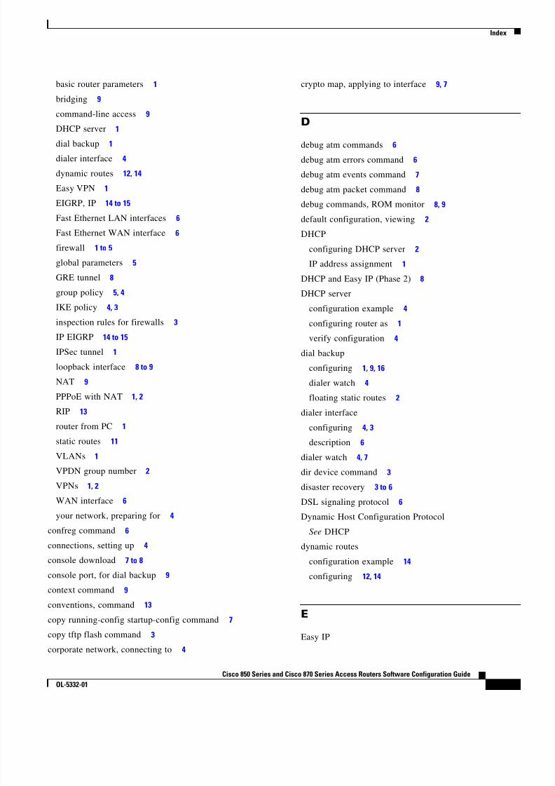
8/11/2019 Cisco 850 Series and Cisco 870 Series
http://slidepdf.com/reader/full/cisco-850-series-and-cisco-870-series 191/196
Index
IN-3Cisco 850 Series and Cisco 870 Series Access Routers Software Configuration Guide
OL-5332-01
basic router parameters 1
bridging 9
command-line access 9
DHCP server 1
dial backup 1
dialer interface 4
dynamic routes 12,14
Easy VPN 1
EIGRP, IP 14 to 15
Fast Ethernet LAN interfaces 6
Fast Ethernet WAN interface 6
firewall 1 to 5
global parameters 5
GRE tunnel 8
group policy 5, 4
IKE policy 4, 3
inspection rules for firewalls 3
IP EIGRP 14 to 15
IPSec tunnel 1
loopback interface 8 to 9
NAT 9
PPPoE with NAT 1, 2
RIP 13router from PC 1
static routes 11
VLANs 1
VPDN group number 2
VPNs 1, 2
WAN interface 6
your network, preparing for 4
confreg command 6
connections, setting up 4
console download 7 to 8
console port, for dial backup 9
context command 9
conventions, command 13
copy running-config startup-config command 7
copy tftp flash command 3
corporate network, connecting to 4
crypto map, applying to interface 9, 7
D
debug atm commands 6
debug atm errors command 6
debug atm events command 7
debug atm packet command 8
debug commands, ROM monitor 8, 9
default configuration, viewing 2
DHCP
configuring DHCP server 2
IP address assignment 1
DHCP and Easy IP (Phase 2) 8
DHCP server
configuration example 4
configuring router as 1
verify configuration 4
dial backup
configuring 1, 9, 16
dialer watch 4
floating static routes 2
dialer interfaceconfiguring 4, 3
description 6
dialer watch 4, 7
dir device command 3
disaster recovery 3 to 6
DSL signaling protocol 6
Dynamic Host Configuration Protocol
See DHCP
dynamic routesconfiguration example 14
configuring 12,14
E
Easy IP

8/11/2019 Cisco 850 Series and Cisco 870 Series
http://slidepdf.com/reader/full/cisco-850-series-and-cisco-870-series 192/196
Index
IN-4Cisco 850 Series and Cisco 870 Series Access Routers Software Configuration Guide
OL-5332-01
Phase 1 overview 8
Phase 2 overview 8
Easy VPN
configuration tasks 3
remote configuration 10
verify configuration 11
EIGRP
configuration example 15
configuring 14
overview 2, 3
enable password
recovering 12
setting 5
enable secret password
recovering 12
setting 5
encapsulation 6
Enhanced Interior Gateway Routing Protocol
See EIGRP
error messages, configuration 6
error reporting, ROM monitor 8
errors, ATM, displaying 6
Ethernet 5events, ATM, displaying 7
experience, user 11
extended access list, overview 11
F
Fast Ethernet LAN interfaces, configuring 6
Fast Ethernet WAN interface, configuring 6, 3
filteringSee access lists
firewalls
access list configuration 3, 2
applying access lists to interfaces 4
applying inspection rules to interfaces 4
configuration example 5
configuration tasks 2
configuring inspection rules 3
floating static routes
description 7
for dial backup 2
flowcontrol command 2
fragmentation, PPP 9
frame command 9
G
G.SHDSL
ordering 4
overview 2
global configuration mode
entering 5
summary 2, 3
global parameters, setting up 5
GRE tunnel
configuration example 9
configuring 8
group policy, configuring 5, 4
H
handshake
defined 2
three-way 4
two-way 4
help command 3
help with commands 4
hop count, defined 3
I
i command 3
IKE policy, configuring 4, 3
inspection rules
applying to interfaces 4

8/11/2019 Cisco 850 Series and Cisco 870 Series
http://slidepdf.com/reader/full/cisco-850-series-and-cisco-870-series 193/196
Index
IN-5Cisco 850 Series and Cisco 870 Series Access Routers Software Configuration Guide
OL-5332-01
configuring 3
interface configuration mode 3
interface port labels (table) 1
interleaving, PPP 9
Internet connection, setting up 4
IP, overview 2
IPCP 8
IP Precedence
with CBWFQ 10
overview 9
IP routing, setting up 4
IPSec tunnel
configuration example 11, 9
configuring 1
crypto method 8, 6
transforms and protocols 7, 5
ISDN
configuring the BRI 17
configuring the peer router 20
S/T port for dial backup 16
ISDN interface, configuring 17
ISDN peer router, configuring 20
K
k command 9
L
LAN with DHCP and VLANs, configuring 1 to 8
LCP 4
LFQ 10line configuration mode 4
Link Control Protocol
See LCP
LLC 6
loopback interface, configuring 8 to 9
low latency queuing
See LFQ
M
meminfo command 9
metrics
EIGRP 3
RIP 3
mode configuration, applying to crypto map 6
modes
See command modes
NNAT
configuration example 8, 11
configuring with PPPoA 9
configuring with PPPoE 1, 6
overview 7 to 8
See also Easy IP (Phase 1)
NCP 4
network address translation
See NATnetwork configuration, preparing for 4
Network Control Protocols
See NCP
network protocols 2
network scenarios
See configuration examples
nonvolatile RAM
See NVRAM
note, described 13NVRAM, saving changes to 7
O
overloading, defined 8
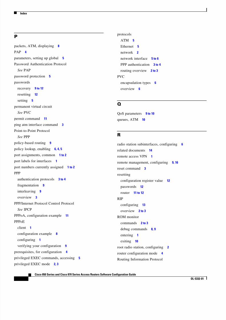
8/11/2019 Cisco 850 Series and Cisco 870 Series
http://slidepdf.com/reader/full/cisco-850-series-and-cisco-870-series 194/196
Index
IN-6Cisco 850 Series and Cisco 870 Series Access Routers Software Configuration Guide
OL-5332-01
P
packets, ATM, displaying 8
PAP 4
parameters, setting up global 5
Password Authentication Protocol
See PAP
password protection 5
passwords
recovery 9 to 12
resetting 12
setting 5
permanent virtual circuit
See PVCpermit command 11
ping atm interface command 3
Point-to-Point Protocol
See PPP
policy-based routing 9
policy lookup, enabling 6, 4, 5
port assignments, common 1 to 2
port labels for interfaces 1
port numbers currently assigned 1 to 2PPP
authentication protocols 3 to 4
fragmentation 9
interleaving 9
overview 3
PPP/Internet Protocol Control Protocol
See IPCP
PPPoA, configuration example 11
PPPoE
client 1
configuration example 8
configuring 1
verifying your configuration 9
prerequisites, for configuration 4
privileged EXEC commands, accessing 5
privileged EXEC mode 2, 3
protocols
ATM 5
Ethernet 5
network 2
network interface 5 to 6
PPP authentication 3 to 4
routing overview 2 to 3
PVC
encapsulation types 6
overview 6
Q
QoS parameters 9 to 10
queues, ATM 10
R
radio station subinterfaces, configuring 6
related documents 14
remote access VPN 1
remote management, configuring 9, 16
reset command 3resetting
configuration register value 12
passwords 12
router 11 to 12
RIP
configuring 13
overview 2 to 3
ROM monitor
commands 2 to 3debug commands 8, 9
entering 1
exiting 10
root radio station, configuring 2
router configuration mode 4
Routing Information Protocol
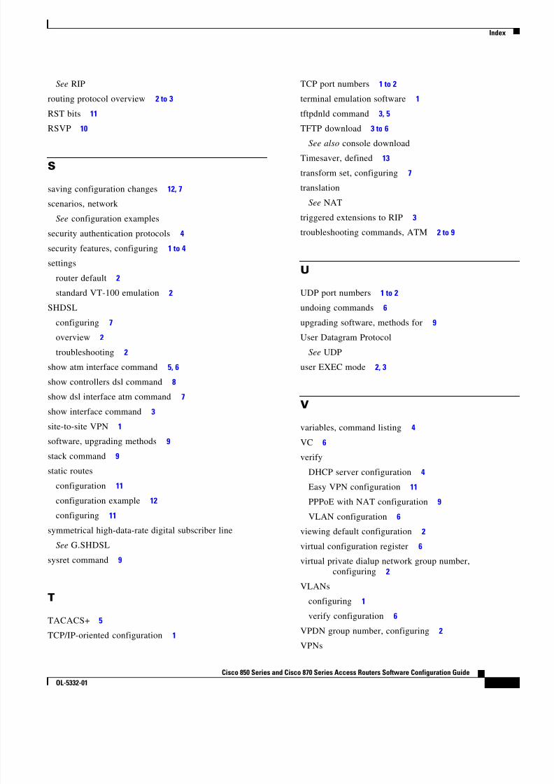
8/11/2019 Cisco 850 Series and Cisco 870 Series
http://slidepdf.com/reader/full/cisco-850-series-and-cisco-870-series 195/196
Index
IN-7Cisco 850 Series and Cisco 870 Series Access Routers Software Configuration Guide
OL-5332-01
See RIP
routing protocol overview 2 to 3
RST bits 11
RSVP 10
S
saving configuration changes 12,7
scenarios, network
See configuration examples
security authentication protocols 4
security features, configuring 1 to 4
settings
router default 2
standard VT-100 emulation 2
SHDSL
configuring 7
overview 2
troubleshooting 2
show atm interface command 5, 6
show controllers dsl command 8
show dsl interface atm command 7
show interface command 3site-to-site VPN 1
software, upgrading methods 9
stack command 9
static routes
configuration 11
configuration example 12
configuring 11
symmetrical high-data-rate digital subscriber line
See G.SHDSLsysret command 9
T
TACACS+ 5
TCP/IP-oriented configuration 1
TCP port numbers 1 to 2
terminal emulation software 1
tftpdnld command 3, 5
TFTP download 3 to 6
See also console download
Timesaver, defined 13
transform set, configuring 7
translation
See NAT
triggered extensions to RIP 3
troubleshooting commands, ATM 2 to 9
UUDP port numbers 1 to 2
undoing commands 6
upgrading software, methods for 9
User Datagram Protocol
See UDP
user EXEC mode 2, 3
V
variables, command listing 4
VC 6
verify
DHCP server configuration 4
Easy VPN configuration 11
PPPoE with NAT configuration 9
VLAN configuration 6
viewing default configuration 2
virtual configuration register 6virtual private dialup network group number,
configuring 2
VLANs
configuring 1
verify configuration 6
VPDN group number, configuring 2
VPNs

8/11/2019 Cisco 850 Series and Cisco 870 Series
http://slidepdf.com/reader/full/cisco-850-series-and-cisco-870-series 196/196
Index
configuration example 11
configuration tasks 3, 2
configuring 1, 4
W
WAN interface, configuring 6, 3
wireless LAN configuration example 7
X
xmodem command 8