configuring hsrp and vrrp · gigabitethernet1/0/1 step 2 ... ip10.0.0.3...
TRANSCRIPT
Configuring UniDirectional Link Detection
• Finding Feature Information, on page 1• Restrictions for Configuring UDLD, on page 1• Information About UDLD, on page 2• How to Configure UDLD, on page 4• Monitoring and Maintaining UDLD, on page 7
Finding Feature InformationYour software release may not support all the features documented in this module. For the latest caveats andfeature information, see Bug Search Tool and the release notes for your platform and software release. Tofind information about the features documented in this module, and to see a list of the releases in which eachfeature is supported, see the feature information table at the end of this module.
Use Cisco Feature Navigator to find information about platform support and Cisco software image support.To access Cisco Feature Navigator, go to http://www.cisco.com/go/cfn. An account on Cisco.com is notrequired.
Restrictions for Configuring UDLDThe following are restrictions for configuring UniDirectional Link Detection (UDLD):
• A UDLD-capable port cannot detect a unidirectional link if it is connected to a UDLD-incapable port ofanother switch.
• When configuring the mode (normal or aggressive), make sure that the same mode is configured on bothsides of the link.
Loop guard works only on point-to-point links.We recommend that each end of the link has a directly connecteddevice that is running STP.
Caution
Configuring UniDirectional Link Detection1
Information About UDLDUniDirectional Link Detection (UDLD) is a Layer 2 protocol that enables devices connected through fiber-opticor twisted-pair Ethernet cables to monitor the physical configuration of the cables and detect when aunidirectional link exists. All connected devices must support UDLD for the protocol to successfully identifyand disable unidirectional links. When UDLD detects a unidirectional link, it disables the affected port andalerts you. Unidirectional links can cause a variety of problems, including spanning-tree topology loops.
Modes of OperationUDLD supports two modes of operation: normal (the default) and aggressive. In normal mode, UDLD candetect unidirectional links due to misconnected ports on fiber-optic connections. In aggressive mode, UDLDcan also detect unidirectional links due to one-way traffic on fiber-optic and twisted-pair links and tomisconnected ports on fiber-optic links.
In normal and aggressive modes, UDLD works with the Layer 1 mechanisms to learn the physical status ofa link. At Layer 1, autonegotiation takes care of physical signaling and fault detection. UDLD performs tasksthat autonegotiation cannot perform, such as detecting the identities of neighbors and shutting downmisconnected ports. When you enable both autonegotiation and UDLD, the Layer 1 and Layer 2 detectionswork together to prevent physical and logical unidirectional connections and the malfunctioning of otherprotocols.
A unidirectional link occurs whenever traffic sent by a local device is received by its neighbor but traffic fromthe neighbor is not received by the local device.
Normal ModeIn normal mode, UDLD detects a unidirectional link when fiber strands in a fiber-optic port are misconnectedand the Layer 1 mechanisms do not detect this misconnection. If the ports are connected correctly but thetraffic is one way, UDLD does not detect the unidirectional link because the Layer 1 mechanism, which issupposed to detect this condition, does not do so. In this case, the logical link is considered undetermined,and UDLD does not disable the port.
When UDLD is in normal mode, if one of the fiber strands in a pair is disconnected, as long as autonegotiationis active, the link does not stay up because the Layer 1 mechanisms detects a physical problem with the link.In this case, UDLD does not take any action and the logical link is considered undetermined.
Related TopicsEnabling UDLD Globally , on page 4Enabling UDLD on an Interface , on page 6
Aggressive ModeIn aggressive mode, UDLD detects a unidirectional link by using the previous detection methods. UDLD inaggressive mode can also detect a unidirectional link on a point-to-point link on which no failure between thetwo devices is allowed. It can also detect a unidirectional link when one of these problems exists:
• On fiber-optic or twisted-pair links, one of the ports cannot send or receive traffic.
• On fiber-optic or twisted-pair links, one of the ports is down while the other is up.
• One of the fiber strands in the cable is disconnected.
Configuring UniDirectional Link Detection2
Configuring UniDirectional Link DetectionInformation About UDLD
In these cases, UDLD disables the affected port.
In a point-to-point link, UDLD hello packets can be considered as a heart beat whose presence guarantees thehealth of the link. Conversely, the loss of the heart beat means that the link must be shut down if it is notpossible to reestablish a bidirectional link.
If both fiber strands in a cable are working normally from a Layer 1 perspective, UDLD in aggressive modedetects whether those fiber strands are connected correctly and whether traffic is flowing bidirectionallybetween the correct neighbors. This check cannot be performed by autonegotiation because autonegotiationoperates at Layer 1.
Related TopicsEnabling UDLD Globally , on page 4Enabling UDLD on an Interface , on page 6
Methods to Detect Unidirectional LinksUDLD operates by using two methods:
• Neighbor database maintenance
• Event-driven detection and echoing
Related TopicsEnabling UDLD Globally , on page 4Enabling UDLD on an Interface , on page 6
Neighbor Database MaintenanceUDLD learns about other UDLD-capable neighbors by periodically sending a hello packet (also called anadvertisement or probe) on every active port to keep each device informed about its neighbors.
When the switch receives a hello message, it caches the information until the age time (hold time or time-to-live)expires. If the switch receives a new hello message before an older cache entry ages, the switch replaces theolder entry with the new one.
Whenever a port is disabled and UDLD is running, whenever UDLD is disabled on a port, or whenever theswitch is reset, UDLD clears all existing cache entries for the ports affected by the configuration change.UDLD sends at least one message to inform the neighbors to flush the part of their caches affected by thestatus change. The message is intended to keep the caches synchronized.
Event-Driven Detection and EchoingUDLD relies on echoing as its detection operation. Whenever a UDLD device learns about a new neighboror receives a resynchronization request from an out-of-sync neighbor, it restarts the detection window on itsside of the connection and sends echo messages in reply. Because this behavior is the same on all UDLDneighbors, the sender of the echoes expects to receive an echo in reply.
If the detection window ends and no valid reply message is received, the link might shut down, depending onthe UDLD mode. When UDLD is in normal mode, the link might be considered undetermined and might notbe shut down.WhenUDLD is in aggressive mode, the link is considered unidirectional, and the port is disabled.
Related TopicsEnabling UDLD Globally , on page 4
Configuring UniDirectional Link Detection3
Configuring UniDirectional Link DetectionMethods to Detect Unidirectional Links
Enabling UDLD on an Interface , on page 6
UDLD Reset OptionsIf an interface becomes disabled by UDLD, you can use one of the following options to reset UDLD:
• The udld reset interface configuration command.
• The shutdown interface configuration command followed by the no shutdown interface configurationcommand restarts the disabled port.
• The no udld {aggressive | enable} global configuration command followed by the udld {aggressive |enable} global configuration command reenables the disabled ports.
• The no udld port interface configuration command followed by the udld port [aggressive] interfaceconfiguration command reenables the disabled fiber-optic port.
• The errdisable recovery cause udld global configuration command enables the timer to automaticallyrecover from the UDLD error-disabled state, and the errdisable recovery interval interval globalconfiguration command specifies the time to recover from the UDLD error-disabled state.
Related TopicsEnabling UDLD Globally , on page 4Enabling UDLD on an Interface , on page 6
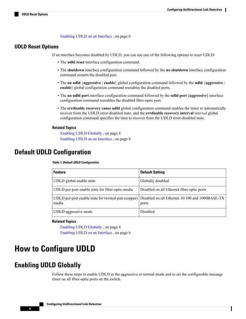
Default UDLD ConfigurationTable 1: Default UDLD Configuration
Default SettingFeature
Globally disabledUDLD global enable state
Disabled on all Ethernet fiber-optic portsUDLD per-port enable state for fiber-optic media
Disabled on all Ethernet 10/100 and 1000BASE-TXports
UDLD per-port enable state for twisted-pair (copper)media
DisabledUDLD aggressive mode
Related TopicsEnabling UDLD Globally , on page 4Enabling UDLD on an Interface , on page 6
How to Configure UDLD
Enabling UDLD GloballyFollow these steps to enable UDLD in the aggressive or normal mode and to set the configurable messagetimer on all fiber-optic ports on the switch.
Configuring UniDirectional Link Detection4
Configuring UniDirectional Link DetectionUDLD Reset Options

SUMMARY STEPS
1. configure terminal2. udld {aggressive | enable |message time message-timer-interval}3. end
DETAILED STEPS
PurposeCommand or Action
Enters global configuration mode.configure terminal
Example:
Step 1
SwitchDevice# configure terminal
Specifies the UDLD mode of operation:udld {aggressive | enable |message timemessage-timer-interval}
Step 2
• aggressive—Enables UDLD in aggressive mode onall fiber-optic ports.Example:
SwitchDevice(config)# udld enable • enable—Enables UDLD in normal mode on allfiber-optic ports on the switch. UDLD is disabled bydefault.
message time 10
An individual interface configuration overrides thesetting of the udld enable global configurationcommand.
• message time message-timer-interval—Configuresthe period of time between UDLD probe messages onports that are in the advertisement phase and aredetected to be bidirectional. The range is from 1 to 90seconds; the default value is 15.
This command affects fiber-optic portsonly. Use the udld interface configurationcommand to enable UDLD on other porttypes.
Note
Use the no form of this command, to disable UDLD.
Returns to privileged EXEC mode.end
Example:
Step 3
SwitchDevice(config)# end
Related TopicsMonitoring and Maintaing UDLDAggressive Mode, on page 2Normal Mode, on page 2
Configuring UniDirectional Link Detection5
Configuring UniDirectional Link DetectionEnabling UDLD Globally
Methods to Detect Unidirectional Links, on page 3Event-Driven Detection and Echoing, on page 3UDLD Reset Options, on page 4Default UDLD Configuration, on page 4
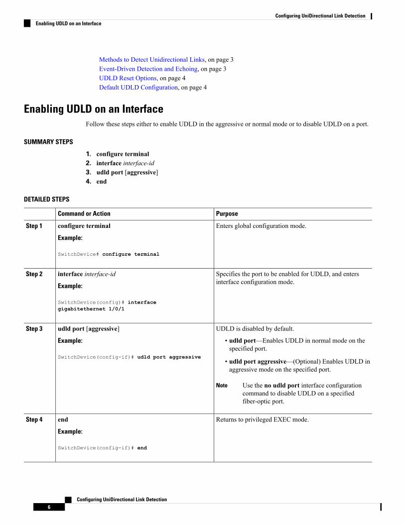
Enabling UDLD on an InterfaceFollow these steps either to enable UDLD in the aggressive or normal mode or to disable UDLD on a port.
SUMMARY STEPS
1. configure terminal2. interface interface-id3. udld port [aggressive]4. end
DETAILED STEPS
PurposeCommand or Action
Enters global configuration mode.configure terminal
Example:
Step 1
SwitchDevice# configure terminal
Specifies the port to be enabled for UDLD, and entersinterface configuration mode.
interface interface-id
Example:
Step 2
SwitchDevice(config)# interfacegigabitethernet 1/0/1
UDLD is disabled by default.udld port [aggressive]Step 3
Example: • udld port—Enables UDLD in normal mode on thespecified port.
SwitchDevice(config-if)# udld port aggressive• udld port aggressive—(Optional) Enables UDLD inaggressive mode on the specified port.
Use the no udld port interface configurationcommand to disable UDLD on a specifiedfiber-optic port.
Note
Returns to privileged EXEC mode.end
Example:
Step 4
SwitchDevice(config-if)# end
Configuring UniDirectional Link Detection6
Configuring UniDirectional Link DetectionEnabling UDLD on an Interface
Related TopicsMonitoring and Maintaing UDLDAggressive Mode, on page 2Normal Mode, on page 2Methods to Detect Unidirectional Links, on page 3Event-Driven Detection and Echoing, on page 3UDLD Reset Options, on page 4Default UDLD Configuration, on page 4
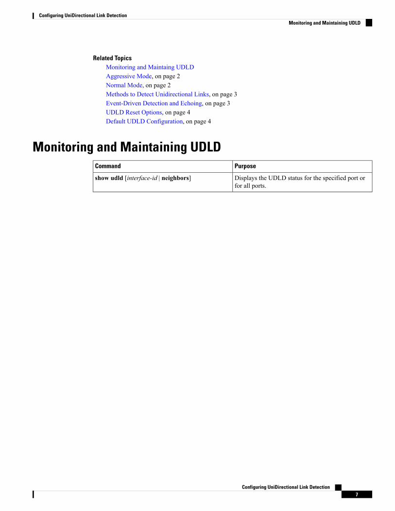
Monitoring and Maintaining UDLDPurposeCommand
Displays the UDLD status for the specified port orfor all ports.
show udld [interface-id | neighbors]
Configuring UniDirectional Link Detection7
Configuring UniDirectional Link DetectionMonitoring and Maintaining UDLD

Configuring UniDirectional Link Detection8
Configuring UniDirectional Link DetectionMonitoring and Maintaining UDLD