virtual router redundancy protocol (vrrp) · virtual router redundancy protocol (vrrp) | page 7...
TRANSCRIPT
Technical Guide
FEATURE OVERVIEW AND CONFIGURATION GUIDE
Virtual Router Redundancy Protocol (VRRP)
VRRP Introduction
This guide describes theVirtual Router Redundancy Protocol (VRRP) feature provided bythe switch, and how to configure the switch to participate in a virtual router.
One function of a switch is to act as a gateway to the WAN for hosts on a LAN. On largerLANs, two or more switches may act as the gateway, and hosts use a dynamic routingprotocol, such as RIP or OSPF, to determine the gateway switch to use as the next hop inorder to reach a specific IP destination. However, there are a number of factors, such asadministrative or processing overhead or even support for the protocols, which may make itundesirable to use a dynamic routing protocol. One alternative is to use static routing;however, if the statically configured first hop switch fails, the hosts on the LAN are unable tocommunicate with those on the WAN.
TheVirtual Router Redundancy Protocol is defined in RFC 5798 (Virtual Router RedundancyProtocol (VRRP)Version 3 for IPv4 and IPv6). It provides a solution to the problem bycombining two or more physical switches into a logical grouping called a virtual router (VR).The physical switches then operate together to provide a single logical gateway for hosts onthe LAN.
A virtual router is configured as the host’s gateway and comprises a number of physicalrouters. The hosts can only see the virtual router so the number of physical routers thatmake up the virtual router is transparent. If physical routers in the virtual router fail, thentraffic to and from the hosts will still be forwarded, so long as there is at least one functioningphysical router, no configuration changes will be required by the hosts.
alliedtelesis.com xC613-22049-00 REV A
VRRP Introduction
Products and software version that apply to this guide
This guide applies to AlliedWare Plus™ products that supportVRRP, running version 5.4.4
or later.
To see whether your product supportsVRRP, see the following documents:
The product’s datasheet
The AlliedWare Plus datasheet
The product’s Command Reference
These documents are available from the above links on our website at alliedtelesis.com.
Feature support may change in later software versions. For the latest information, see theabove documents.
Content
VRRP Introduction...............................................................................................................................................................1
Products and software version that apply to this guide .......................................................................2
Virtual Router Redundancy Protocol .......................................................................................................................3
VRRP Configuration for IPv4.........................................................................................................................................5
VRRP election and preempt for IPv4 ..............................................................................................................7
VRRP Configuration for IPv6.........................................................................................................................................9
VRRP election and preempt for IPv6 ........................................................................................................... 11
VRRP Debugging ............................................................................................................................................................... 13
VRRP Configuration Examples .................................................................................................................................. 14
VRRP preferred master with backup configuration ............................................................................. 14
VRRP circuit failover configuration................................................................................................................. 17
VRRPv2 to VRRPv3 transition configuration ............................................................................................ 22
Virtual Router Redundancy Protocol IPv6 (VRRPv3) configuration .......................................... 28
Page 2 | Virtual Router Redundancy Protocol (VRRP)
Virtual Router Redundancy Protocol
Virtual Router Redundancy Protocol
TheVRRP virtual router comprises a master router and a number of backup routers. Themaster router is the router responsible for forwarding packets between the hosts and theremote network. It is also responsible for informing the backup router(s) of its presence.Should the master router fail, then one of the backup routers takes over the master routerrole.
The virtual router uses a special reserved MAC address, which is called theVRRP virtualMAC.This MAC address is returned by the master router of the virtual router in any ARPresponses relating to the gateway IP address, regardless of which device is acting as themaster router. By using this shared MAC address across routers, host maintain connectivitywith the remote network if a router fails with a backup taking over as master.
Note: If there are PIM-SM routers using VRRP, the Bootstrap Router (BSR) function will not
work properly
The virtual router has a virtual MAC address that is known by all its participating switches orrouters.The virtual MAC address is derived from the virtual router identifier - a user-definedvalue from 1 to 255. At the network level, all hosts on the LAN are configured with acommon IP address that is used as the first hop. This IP address is typically owned by thevirtual router’s preferred individual switch or router. When available, this device performs theduties of the virtual router, and is referred to as the master. The switch that owns the IPaddress associated with the virtual router is referred to as the preferred master. When avirtual router is configured so that none of the participating switches owns the IP address,the virtual router has no preferred master.
When a switch takes the role of master for a virtual router, it is responsible for the following:
Responding to ARP and Neighbor solicitation packets that contain IP addresses associatedwith the virtual router. The ARP reply or Neighbor response contains the virtual MACaddress of the virtual router so that the hosts on the LAN associate the virtual MACaddress with their configured first-hop IP address. Note that withVRRPv3 supporting bothIPv4 and IPv6, the IP address in this context can be an IPv4 or an IPv6 address.
Forwarding packets with a destination link layer MAC address equal to the virtual routerMAC address.
TheVRRPv3 accept mode is enabled by default in the AlliedWare PlusVRRPv3implementation. This enables aVRRP master to accept packets addressed to the virtualrouter IP address even if this IP address is not owned by theVRRP master.
Broadcasting advertisement packets at regular intervals (at the specified advertisementinterval) to inform backup switches that it is still acting as the master switch.
Virtual Router Redundancy Protocol (VRRP) | Page 3
Virtual Router Redundancy Protocol
Each of the other switches participating in the virtual router is considered to be a backupswitch.
A switch can be a member of several different virtual routers on one LAN, but each virtualrouter must have a unique identifier (VRID). When a switch has the role of backup for avirtual router, it must be able to perform the following tasks:
Receive advertisement packets from the master and check that the information containedin them is consistent with their own configuration; ignoring and discarding advertisementpackets that do not match.
Assume the role of master for the virtual router if an advertisement packet is not receivedfor a given period (the master-down time), based on the specified advertisement interval(for example, the command: awplus(config-router)# advertisement-interval 5 will setthe advertisement-interval to 5 seconds). The master-down time is approximately threetimes the advertisement interval.
Assume the role of master if it receives an advertisement packet from another switch witha lower priority than its own, and if preempt mode is on.
If aVRRP instance is running on aVLAN interface and theVLAN interface goes down, thentheVRRP instance, whether it is aVRRP master or aVRRP backup, moves to an INIT state.When in the INIT state theVRRP instance on theVLAN interface cannot receive traffic, andwill not be active until theVLAN interface is up
Note: When using VRRPv3 with VCStacking, ensure that the VRRPv3 advertisement-interval
is configured to a longer time than the VCStacking failover time. If the VRRPv3
advertisement-interval is shorter than the VCStacking failover time, then a VRRPv3
failover will also occur whenever a VCStacking failover occurs. Use seconds not
centiseconds to ensure interoperability with VRRPv2.
Page 4 | Virtual Router Redundancy Protocol (VRRP)
VRRP Configuration for IPv4
VRRP Configuration for IPv4
VRRP for IPv4 is disabled by default. Once you have defined a virtual router session, youmust enableVRRP to make the session operational for a given interface.
You can then enable or disable the virtual router as shown:
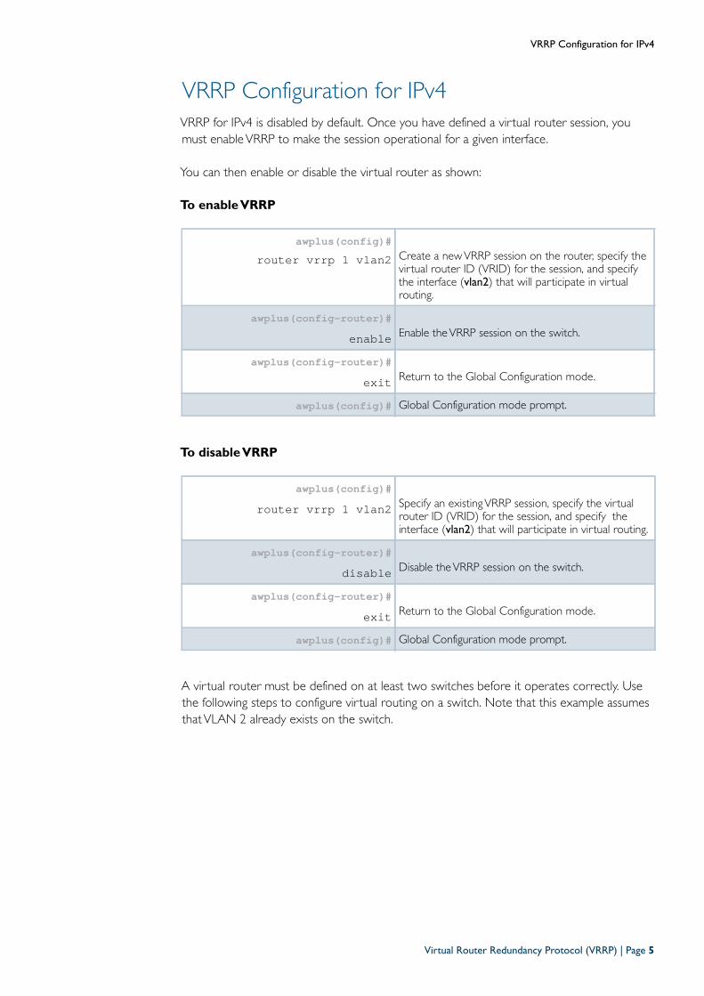
To enable VRRP
To disable VRRP
A virtual router must be defined on at least two switches before it operates correctly. Usethe following steps to configure virtual routing on a switch. Note that this example assumesthatVLAN 2 already exists on the switch.
awplus(config)#router vrrp 1 vlan2 Create a newVRRP session on the router, specify the
virtual router ID (VRID) for the session, and specifythe interface (vlan2) that will participate in virtualrouting.
awplus(config-router)#enable Enable theVRRP session on the switch.
awplus(config-router)#exit Return to the Global Configuration mode.
awplus(config)# Global Configuration mode prompt.
awplus(config)#router vrrp 1 vlan2 Specify an existingVRRP session, specify the virtual
router ID (VRID) for the session, and specify theinterface (vlan2) that will participate in virtual routing.
awplus(config-router)#disable Disable theVRRP session on the switch.
awplus(config-router)#exit Return to the Global Configuration mode.
awplus(config)# Global Configuration mode prompt.
Virtual Router Redundancy Protocol (VRRP) | Page 5
VRRP Configuration for IPv4
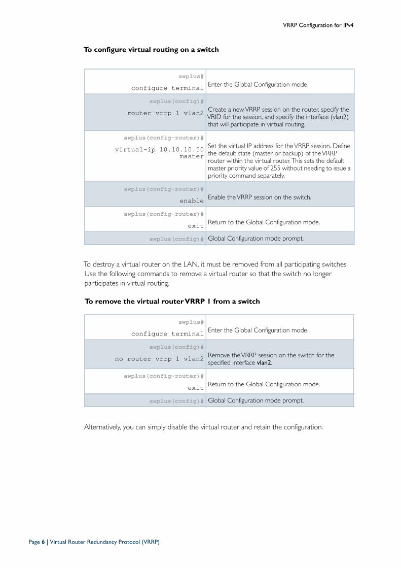
To configure virtual routing on a switch
To destroy a virtual router on the LAN, it must be removed from all participating switches.Use the following commands to remove a virtual router so that the switch no longerparticipates in virtual routing.
To remove the virtual router VRRP 1 from a switch
Alternatively, you can simply disable the virtual router and retain the configuration.
awplus#configure terminal Enter the Global Configuration mode.
awplus(config)#router vrrp 1 vlan2 Create a newVRRP session on the router, specify the
VRID for the session, and specify the interface (vlan2)that will participate in virtual routing.
awplus(config-router)#virtual-ip 10.10.10.50
masterSet the virtual IP address for theVRRP session. Definethe default state (master or backup) of theVRRProuter within the virtual router. This sets the defaultmaster priority value of 255 without needing to issue apriority command separately.
awplus(config-router)#enable Enable theVRRP session on the switch.
awplus(config-router)#exit Return to the Global Configuration mode.
awplus(config)# Global Configuration mode prompt.
awplus#configure terminal Enter the Global Configuration mode.
awplus(config)#no router vrrp 1 vlan2 Remove theVRRP session on the switch for the
specified interface vlan2.
awplus(config-router)#exit Return to the Global Configuration mode.
awplus(config)# Global Configuration mode prompt.
Page 6 | Virtual Router Redundancy Protocol (VRRP)
VRRP Configuration for IPv4
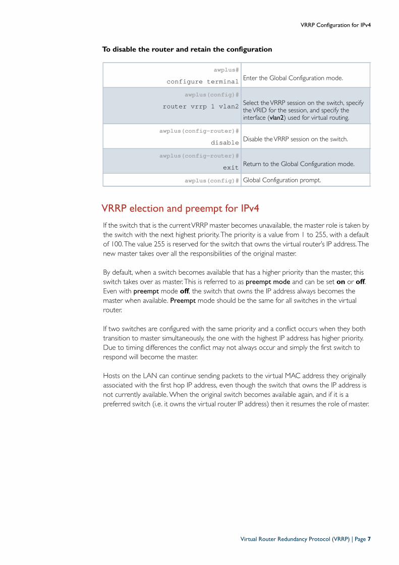
To disable the router and retain the configuration
VRRP election and preempt for IPv4
If the switch that is the currentVRRP master becomes unavailable, the master role is taken bythe switch with the next highest priority. The priority is a value from 1 to 255, with a defaultof 100.The value 255 is reserved for the switch that owns the virtual router’s IP address.Thenew master takes over all the responsibilities of the original master.
By default, when a switch becomes available that has a higher priority than the master, thisswitch takes over as master. This is referred to as preempt mode and can be set on or off.Even with preempt mode off, the switch that owns the IP address always becomes themaster when available. Preempt mode should be the same for all switches in the virtualrouter.
If two switches are configured with the same priority and a conflict occurs when they bothtransition to master simultaneously, the one with the highest IP address has higher priority.Due to timing differences the conflict may not always occur and simply the first switch torespond will become the master.
Hosts on the LAN can continue sending packets to the virtual MAC address they originallyassociated with the first hop IP address, even though the switch that owns the IP address isnot currently available. When the original switch becomes available again, and if it is apreferred switch (i.e. it owns the virtual router IP address) then it resumes the role of master.
awplus#configure terminal Enter the Global Configuration mode.
awplus(config)#router vrrp 1 vlan2 Select theVRRP session on the switch, specify
theVRID for the session, and specify theinterface (vlan2) used for virtual routing.
awplus(config-router)#disable Disable theVRRP session on the switch.
awplus(config-router)#exit Return to the Global Configuration mode.
awplus(config)# Global Configuration prompt.
Virtual Router Redundancy Protocol (VRRP) | Page 7
VRRP Configuration for IPv4
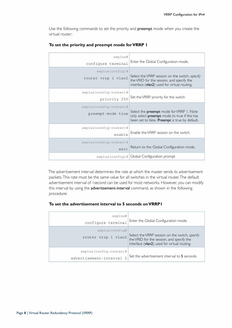
Use the following commands to set the priority and preempt mode when you create thevirtual router :
To set the priority and preempt mode for VRRP 1
The advertisement interval determines the rate at which the master sends its advertisementpackets. This rate must be the same value for all switches in the virtual router. The defaultadvertisement interval of 1second can be used for most networks. However, you can modifythis interval by using the advertisement-interval command, as shown in the followingprocedure:
To set the advertisement interval to 5 seconds on VRRP1
awplus#configure terminal Enter the Global Configuration mode.
awplus(config)# router vrrp 1 vlan2 Select theVRRP session on the switch, specify
theVRID for the session, and specify theinterface (vlan2) used for virtual routing.
awplus(config-router)#priority 255 Set theVRRP priority for the switch
awplus(config-router)#preempt-mode true Select the preempt mode forVRRP 1. Note
only select preempt mode to true if this hasbeen set to false. Preempt is true by default.
awplus(config-router)#enable Enable theVRRP session on the switch.
awplus(config-router)#exit Return to the Global Configuration mode.
awplus(config)# Global Configuration prompt
awplus#configure terminal Enter the Global Configuration mode.
awplus(config#router vrrp 1 vlan2 Select theVRRP session on the switch, specify
theVRID for the session, and specify theinterface (vlan2) used for virtual routing.
awplus(config-router)#advertisement-interval 5 Set the advertisement interval to 5 seconds.
Page 8 | Virtual Router Redundancy Protocol (VRRP)
VRRP Configuration for IPv6
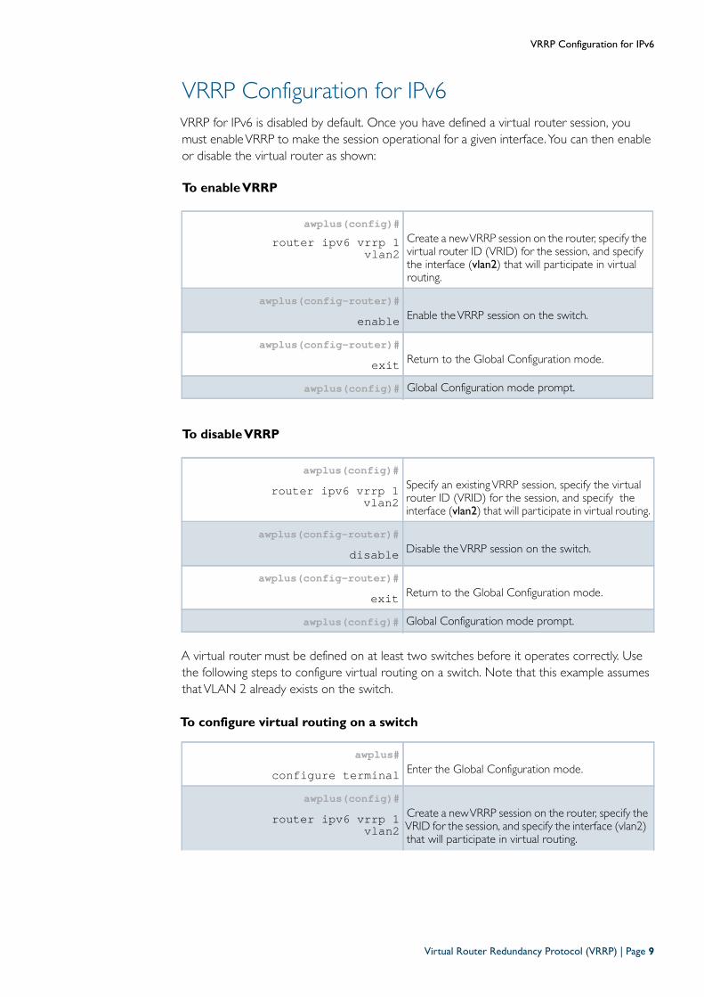
VRRP Configuration for IPv6
VRRP for IPv6 is disabled by default. Once you have defined a virtual router session, youmust enableVRRP to make the session operational for a given interface.You can then enableor disable the virtual router as shown:
To enable VRRP
To disable VRRP
A virtual router must be defined on at least two switches before it operates correctly. Usethe following steps to configure virtual routing on a switch. Note that this example assumesthatVLAN 2 already exists on the switch.
To configure virtual routing on a switch
awplus(config)#router ipv6 vrrp 1
vlan2Create a newVRRP session on the router, specify thevirtual router ID (VRID) for the session, and specifythe interface (vlan2) that will participate in virtualrouting.
awplus(config-router)#enable Enable theVRRP session on the switch.
awplus(config-router)#exit Return to the Global Configuration mode.
awplus(config)# Global Configuration mode prompt.
awplus(config)#router ipv6 vrrp 1
vlan2Specify an existingVRRP session, specify the virtualrouter ID (VRID) for the session, and specify theinterface (vlan2) that will participate in virtual routing.
awplus(config-router)#disable Disable theVRRP session on the switch.
awplus(config-router)#exit Return to the Global Configuration mode.
awplus(config)# Global Configuration mode prompt.
awplus#configure terminal Enter the Global Configuration mode.
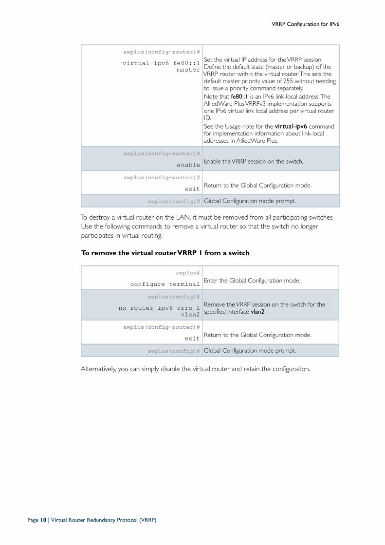
awplus(config)#router ipv6 vrrp 1
vlan2Create a newVRRP session on the router, specify theVRID for the session, and specify the interface (vlan2)that will participate in virtual routing.
Virtual Router Redundancy Protocol (VRRP) | Page 9
VRRP Configuration for IPv6
To destroy a virtual router on the LAN, it must be removed from all participating switches.Use the following commands to remove a virtual router so that the switch no longerparticipates in virtual routing.
To remove the virtual router VRRP 1 from a switch
Alternatively, you can simply disable the virtual router and retain the configuration.
awplus(config-router)#virtual-ipv6 fe80::1
masterSet the virtual IP address for theVRRP session.Define the default state (master or backup) of theVRRP router within the virtual router. This sets thedefault master priority value of 255 without needingto issue a priority command separately.Note that fe80::1 is an IPv6 link-local address. TheAlliedWare PlusVRRPv3 implementation supportsone IPv6 virtual link local address per virtual routerID.See the Usage note for the virtual-ipv6 commandfor implementation information about link-localaddresses in AlliedWare Plus.
awplus(config-router)#enable Enable theVRRP session on the switch.
awplus(config-router)#exit Return to the Global Configuration mode.
awplus(config)# Global Configuration mode prompt.
awplus#configure terminal Enter the Global Configuration mode.
awplus(config)#no router ipv6 vrrp 1
vlan2Remove theVRRP session on the switch for thespecified interface vlan2.
awplus(config-router)#exit Return to the Global Configuration mode.
awplus(config)# Global Configuration mode prompt.
Page 10 | Virtual Router Redundancy Protocol (VRRP)
VRRP Configuration for IPv6
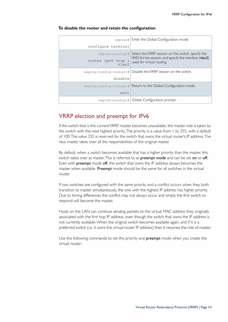
To disable the router and retain the configuration
VRRP election and preempt for IPv6
If the switch that is the currentVRRP master becomes unavailable, the master role is taken bythe switch with the next highest priority. The priority is a value from 1 to 255, with a defaultof 100.The value 255 is reserved for the switch that owns the virtual router’s IP address.Thenew master takes over all the responsibilities of the original master.
By default, when a switch becomes available that has a higher priority than the master, thisswitch takes over as master. This is referred to as preempt mode and can be set on or off.Even with preempt mode off, the switch that owns the IP address always becomes themaster when available. Preempt mode should be the same for all switches in the virtualrouter.
If two switches are configured with the same priority and a conflict occurs when they bothtransition to master simultaneously, the one with the highest IP address has higher priority.Due to timing differences the conflict may not always occur and simply the first switch torespond will become the master.
Hosts on the LAN can continue sending packets to the virtual MAC address they originallyassociated with the first hop IP address, even though the switch that owns the IP address isnot currently available. When the original switch becomes available again, and if it is apreferred switch (i.e. it owns the virtual router IP address) then it resumes the role of master.
Use the following commands to set the priority and preempt mode when you create thevirtual router :
awplus#configure terminal
Enter the Global Configuration mode.
awplus(config)#router ipv6 vrrp 1
vlan2
Select theVRRP session on the switch, specify theVRID for the session, and specify the interface (vlan2)used for virtual routing.
awplus(config-router)#disable
Disable theVRRP session on the switch.
awplus(config-router)#exit
Return to the Global Configuration mode.
awplus(config)# Global Configuration prompt.
Virtual Router Redundancy Protocol (VRRP) | Page 11
VRRP Configuration for IPv6
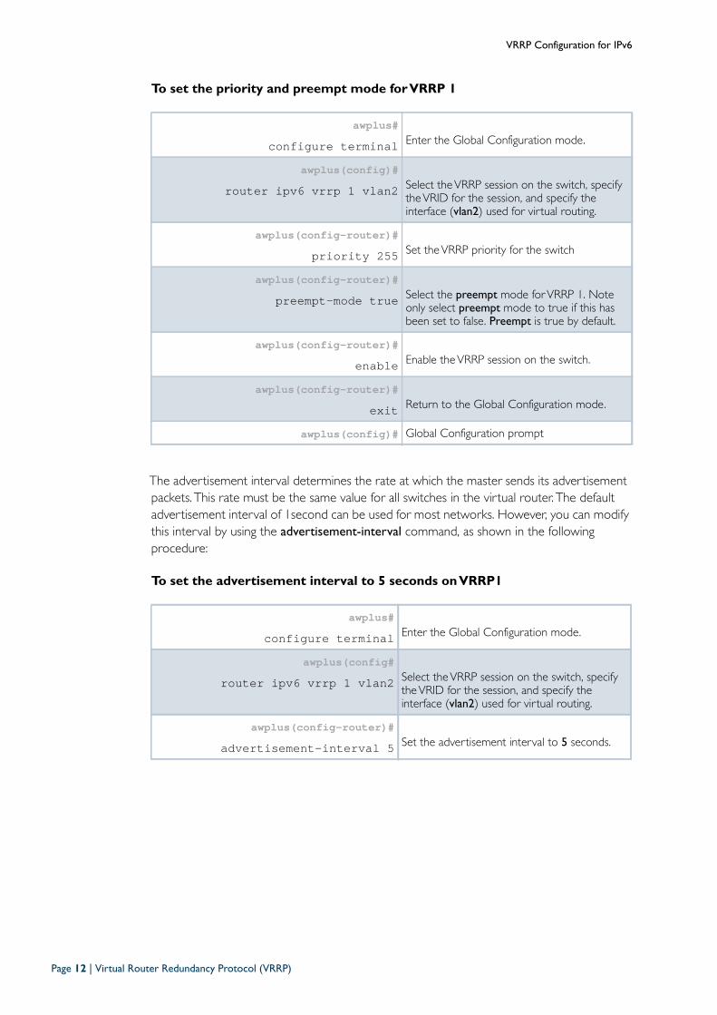
To set the priority and preempt mode for VRRP 1
The advertisement interval determines the rate at which the master sends its advertisementpackets. This rate must be the same value for all switches in the virtual router. The defaultadvertisement interval of 1second can be used for most networks. However, you can modifythis interval by using the advertisement-interval command, as shown in the followingprocedure:
To set the advertisement interval to 5 seconds on VRRP1
awplus#configure terminal Enter the Global Configuration mode.
awplus(config)# router ipv6 vrrp 1 vlan2 Select theVRRP session on the switch, specify
theVRID for the session, and specify theinterface (vlan2) used for virtual routing.
awplus(config-router)#priority 255 Set theVRRP priority for the switch
awplus(config-router)#preempt-mode true Select the preempt mode forVRRP 1. Note
only select preempt mode to true if this hasbeen set to false. Preempt is true by default.
awplus(config-router)#enable Enable theVRRP session on the switch.
awplus(config-router)#exit Return to the Global Configuration mode.
awplus(config)# Global Configuration prompt
awplus#configure terminal Enter the Global Configuration mode.
awplus(config#router ipv6 vrrp 1 vlan2 Select theVRRP session on the switch, specify
theVRID for the session, and specify theinterface (vlan2) used for virtual routing.
awplus(config-router)#advertisement-interval 5 Set the advertisement interval to 5 seconds.
Page 12 | Virtual Router Redundancy Protocol (VRRP)
VRRP Debugging
VRRP Debugging
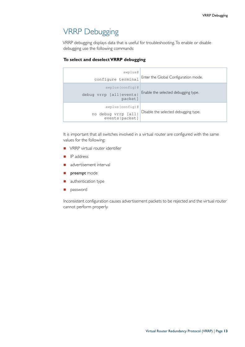
VRRP debugging displays data that is useful for troubleshooting. To enable or disabledebugging use the following commands:
To select and deselect VRRP debugging
It is important that all switches involved in a virtual router are configured with the samevalues for the following:
VRRP virtual router identifier
IP address
advertisement interval
preempt mode
authentication type
password
Inconsistent configuration causes advertisement packets to be rejected and the virtual routercannot perform properly.
awplus#configure terminal Enter the Global Configuration mode.
awplus(config)#debug vrrp [all|events|
packet]Enable the selected debugging type.
awplus(config)#no debug vrrp [all|
events|packet]Disable the selected debugging type.
Virtual Router Redundancy Protocol (VRRP) | Page 13
VRRP Configuration Examples
VRRP Configuration Examples
The following examples show how to configure a virtual router in a LAN:
"VRRP preferred master with backup configuration" on page 14
"VRRP circuit failover configuration" on page 17
"VRRPv2 toVRRPv3 transition configuration" on page 22
"Virtual Router Redundancy Protocol IPv6 (VRRPv3) configuration" on page 28
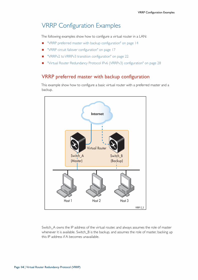
VRRP preferred master with backup configuration
This example show how to configure a basic virtual router with a preferred master and abackup.
Switch_A owns the IP address of the virtual router, and always assumes the role of masterwhenever it is available. Switch_B is the backup, and assumes the role of master, backing upthis IP address if A becomes unavailable.
Host 1 Host 2 Host 3
VRRP-2_S
Virtual Router
Switch_BSwitch_A(Master) (Backup)
Internet
Page 14 | Virtual Router Redundancy Protocol (VRRP)
VRRP Configuration Examples
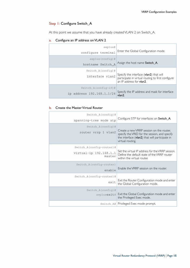
Step 1: Configure Switch_A
At this point we assume that you have already createdVLAN 2 on Switch_A.
a. Configure an IP address on VLAN 2
b. Create the Master Virtual Router
awplus#configure terminal Enter the Global Configuration mode.
awplus(config)#hostname Switch_A Assign the host name Switch_A.
Switch_A(config)#interface vlan2 Specify the interface (vlan2) that will
participate in virtual routing to first configurean IP address for vlan2.
Switch_A(config-if)#ip address 192.168.1.1/24 Specify the IP address and mask for interface
vlan2.
Switch_A(config)#spanning-tree mode stp Configure STP for interfaces on Switch_A.
Switch_A(config)#router vrrp 1 vlan2 Create a newVRRP session on the router,
specify theVRID for the session, and specifythe interface (vlan2) that will participate invirtual routing.
Switch_A(config-router)#virtual-ip 192.168.1.1
masterSet the virtual IP address for theVRRP session.Define the default state of theVRRP routerwithin the virtual router.
Switch_A(config-router)enable Enable theVRRP session on the router.
Switch_A(config-router)#exit Exit the Router Configuration mode and enter
the Global Configuration mode.
Switch_A(config)#awplusexit# Exit the Global Configuration mode and enter
the Privileged Exec mode.
Switch_A# Privileged Exec mode prompt.
Virtual Router Redundancy Protocol (VRRP) | Page 15
VRRP Configuration Examples
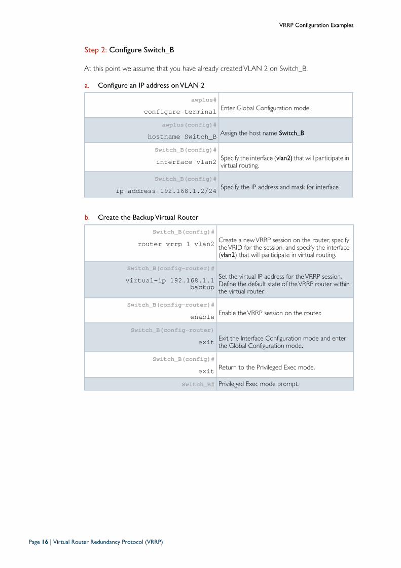
Step 2: Configure Switch_B
At this point we assume that you have already createdVLAN 2 on Switch_B.
a. Configure an IP address on VLAN 2
b. Create the Backup Virtual Router
awplus#configure terminal Enter Global Configuration mode.
awplus(config)#hostname Switch_B Assign the host name Switch_B.
Switch_B(config)#interface vlan2 Specify the interface (vlan2) that will participate in
virtual routing.
Switch_B(config)#ip address 192.168.1.2/24 Specify the IP address and mask for interface
Switch_B(config)#router vrrp 1 vlan2 Create a newVRRP session on the router, specify
theVRID for the session, and specify the interface(vlan2) that will participate in virtual routing.
Switch_B(config-router)#virtual-ip 192.168.1.1
backupSet the virtual IP address for theVRRP session.Define the default state of theVRRP router withinthe virtual router.
Switch_B(config-router)#enable Enable theVRRP session on the router.
Switch_B(config-router)exit Exit the Interface Configuration mode and enter
the Global Configuration mode.
Switch_B(config)#exit Return to the Privileged Exec mode.
Switch_B# Privileged Exec mode prompt.
Page 16 | Virtual Router Redundancy Protocol (VRRP)
VRRP Configuration Examples
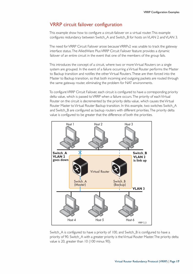
VRRP circuit failover configuration
This example show how to configure a circuit-failover on a virtual router. This exampleconfigures redundancy between Switch_A and Switch_B for hosts onVLAN 2 andVLAN 3.
The need forVRRP Circuit Failover arose becauseVRRPv2 was unable to track the gatewayinterface status. The AlliedWare PlusVRRP Circuit Failover feature provides a dynamicfailover of an entire circuit in the event that one of the members of the group fails.
This introduces the concept of a circuit, where two or moreVirtual Routers on a singlesystem are grouped. In the event of a failure occurring aVirtual Router performs the Masterto Backup transition and notifies the otherVirtual Routers. These are then forced into theMaster to Backup transition, so that both incoming and outgoing packets are routed throughthe same gateway router, eliminating the problem for NAT environments.
To configureVRRP Circuit Failover, each circuit is configured to have a corresponding prioritydelta value, which is passed toVRRP when a failure occurs. The priority of eachVirtualRouter on the circuit is decremented by the priority delta value, which causes theVirtualRouter Master toVirtual Router Backup transition. In this example, two switches Switch_Aand Switch_B are configured as backup routers with different priorities. The priority deltavalue is configured to be greater that the difference of both the priorities.
Switch_A is configured to have a priority of 100, and Switch_B is configured to have apriority of 90. Switch_A with a greater priority is theVirtual Router Master.The priority deltavalue is 20, greater than 10 (100 minus 90).
Host 4 Host 5 Host 6VRRP-3_S
Virtual Router
Switch_B Switch_A(Master) (Backup)
VLAN 3
VLAN 2
Host 1 Host 2 Host 3
Switch_AVLAN 2goes down
Switch_B
is link up
Virtual Router Redundancy Protocol (VRRP) | Page 17
VRRP Configuration Examples
On Switch_A, when vlan2 fails, the priority of Switch_A becomes 80 (100 minus 20). SinceSwitch_B has a greater priority (90) than Switch_A, Switch_B becomes theVirtual RouterMaster, and routing of packets continues without interruption. When thisVirtual RouterBackup (Switch_A) is up again, it regains its original priority (100), and becomes theVirtualRouter Master again.
Step 1: Configure Switch_A
a. Configure an IP address on VLAN 2
b. Configure an IP address on VLAN 3
c. Create the Master Virtual Router
awplus#configure terminal Enter the Global Configuration mode.
awplus(config)#hostname Switch_A Assign the host name Switch_A.
Switch_A(config)#interface vlan2 Specify the interface (vlan2) that will
participate in virtual routing to first configurean IP address for vlan2.
Switch_A(config-if)#ip address 192.168.1.1/24 Specify the IP address and mask for interface
vlan2.
Switch_A(config-if)#exit Exit the Interface Configuration mode and
enter the Global Configuration mode.
Switch_A(config)#interface vlan3 Specify the interface (vlan3) that will
participate in virtual routing to first configurean IP address for vlan3.
Switch_A(config-if)#ip address 192.168.2.1/24 Specify the IP address and mask for interface
vlan3.
Switch_A(config)#router vrrp 1 vlan2 Create a newVRRP session on the router,
specify theVRID for the session, and specify theinterface (vlan2) that will participate in virtualrouting.
Switch_A(config-router)#virtual-ip 192.168.1.1
backupSet the virtual IP address for theVRRP session.Define the default state of theVRRP routerwithin the virtual router.
Switch_A(config-router)#priority 100 Set theVRRP priority to 100 as the default
priority for a BackupVirtual Router.
Page 18 | Virtual Router Redundancy Protocol (VRRP)
VRRP Configuration Examples
Switch_A(config-router)#preempt-mode true Set preempt mode to true to specify that the
highest priority will own the virtual IP addresswhen there is a failure and will function as theBackupVirtual Router.
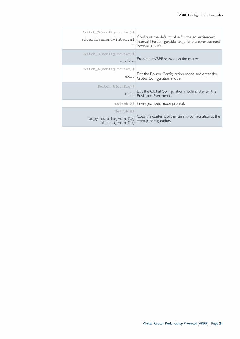
Switch_B(config-router)#advertisement-interval 5 Configure the default value for the
advertisement interval.The configurable rangefor the advertisement interval is 1-10.
Switch_A(config-router)#circuit-failover vlan2 20 Configure circuit failover to 20 on Switch_A.
This configures a priority delta value, greaterthan the difference of priorities on master andbackup routers.This priority delta value is subtracted from thecurrentVR Master Router priority value.
Switch_A(config-router)#enable Enable theVRRP session on the router.
Switch_A(config-router)#exit Exit the Router Configuration mode and enter
the Global Configuration mode.
Switch_A(config)#exit Exit the Global Configuration mode and enter
the Privileged Exec mode.
Switch_A# Privileged Exec mode prompt.
Switch_A#copy running-config
startup-configCopy the contents of the running-configurationto the startup-configuration.
Virtual Router Redundancy Protocol (VRRP) | Page 19
VRRP Configuration Examples
Step 2: Configure Switch_B
At this point we assume that you have already createdVLAN2 on Switch_B.
a. Configure an IP address on VLAN 2
b. Configure an IP address on VLAN 3
c. Create the backup virtual router
awplus#configure terminal Enter Global Configuration mode.
awplus(config)#hostname Switch_B Assign the host name Switch_B.
Switch_B(config)#interface vlan2 Specify the interface (vlan2) that will participate in
virtual routing.
Switch_B(config-if)#ip address 192.168.1.2/24 Specify the IP address and mask for the interface
Switch_B(config-if)#exit Exit the Interface Configuration mode and enter
the Global Configuration mode.
Switch_B(config)#interface vlan3 Specify the interface (vlan3) that will participate in
virtual routing.
Switch_B(config-if)#ip address 192.168.2.2/24 Specify the IP address and mask for the interface
Switch_B(config)#router vrrp 1 vlan2 Create a newVRRP session on the router, specify the
VRID for the session, and specify the interface (vlan2)that will participate in virtual routing.
Switch_B(config-router)#virtual-ip 192.168.1.1
backupSet the virtual IP address for theVRRP session. Definethe default state of theVRRP router within the virtualrouter.
Switch_B(config-router)#priority 90 Set theVRRP priority to 90 (less than 100) because
Switch_B is the BackupVirtual Router.
Switch_B(config-router)#preempt-mode true Set preempt mode to true to specify that the highest
priority will own the virtual IP address when there isa failure and will function as the BackupVirtual Router.
Page 20 | Virtual Router Redundancy Protocol (VRRP)
VRRP Configuration Examples
Switch_B(config-router)#advertisement-interval
5Configure the default value for the advertisementinterval.The configurable range for the advertisementinterval is 1-10.
Switch_B(config-router)#enable Enable theVRRP session on the router.
Switch_A(config-router)#exit Exit the Router Configuration mode and enter the
Global Configuration mode.
Switch_A(config)#exit Exit the Global Configuration mode and enter the
Privileged Exec mode.
Switch_A# Privileged Exec mode prompt.
Switch_A# copy running-config
startup-configCopy the contents of the running-configuration to thestartup-configuration.
Virtual Router Redundancy Protocol (VRRP) | Page 21
VRRP Configuration Examples
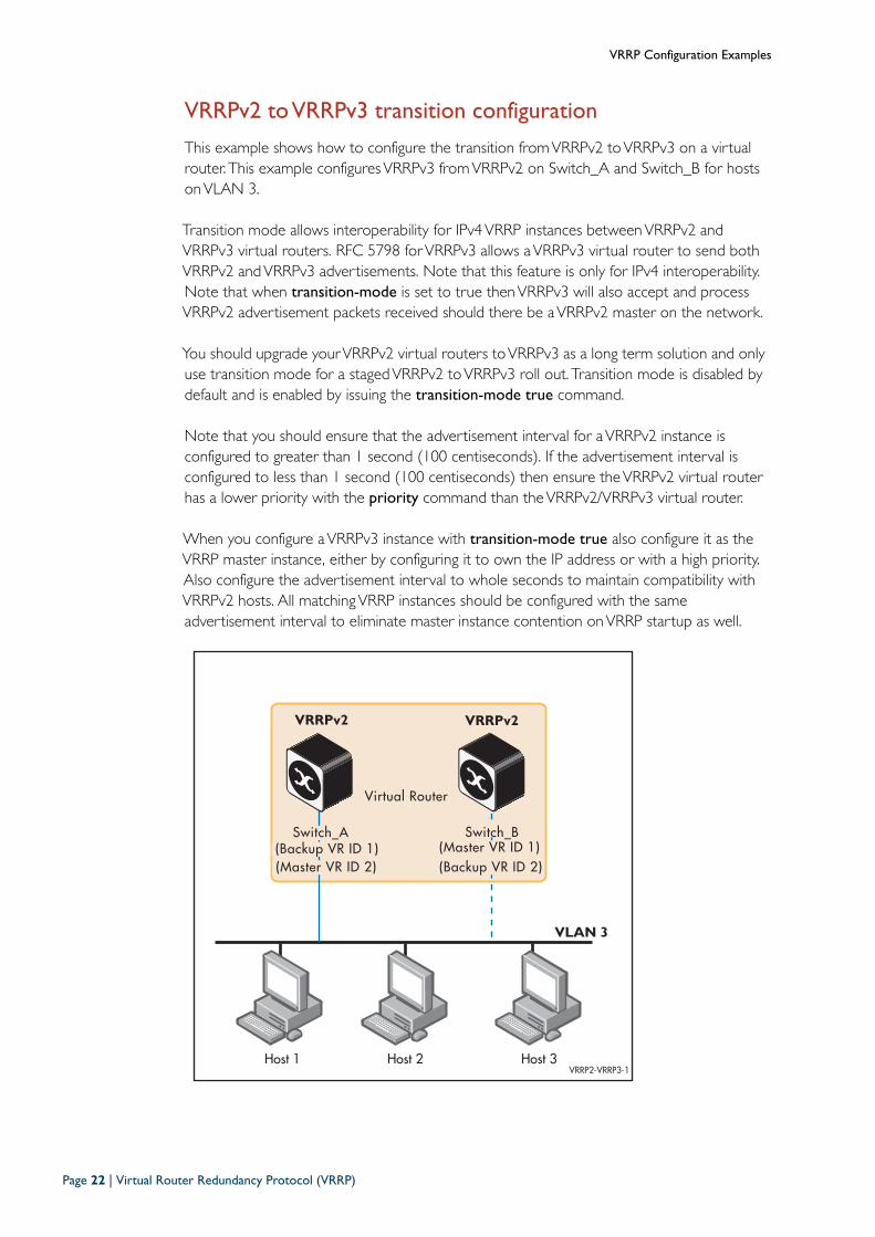
VRRPv2 to VRRPv3 transition configuration
This example shows how to configure the transition fromVRRPv2 toVRRPv3 on a virtualrouter. This example configuresVRRPv3 fromVRRPv2 on Switch_A and Switch_B for hostsonVLAN 3.
Transition mode allows interoperability for IPv4VRRP instances betweenVRRPv2 andVRRPv3 virtual routers. RFC 5798 forVRRPv3 allows aVRRPv3 virtual router to send bothVRRPv2 andVRRPv3 advertisements. Note that this feature is only for IPv4 interoperability.Note that when transition-mode is set to true thenVRRPv3 will also accept and processVRRPv2 advertisement packets received should there be aVRRPv2 master on the network.
You should upgrade yourVRRPv2 virtual routers toVRRPv3 as a long term solution and onlyuse transition mode for a stagedVRRPv2 toVRRPv3 roll out. Transition mode is disabled bydefault and is enabled by issuing the transition-mode true command.
Note that you should ensure that the advertisement interval for aVRRPv2 instance isconfigured to greater than 1 second (100 centiseconds). If the advertisement interval isconfigured to less than 1 second (100 centiseconds) then ensure theVRRPv2 virtual routerhas a lower priority with the priority command than theVRRPv2/VRRPv3 virtual router.
When you configure aVRRPv3 instance with transition-mode true also configure it as theVRRP master instance, either by configuring it to own the IP address or with a high priority.Also configure the advertisement interval to whole seconds to maintain compatibility withVRRPv2 hosts. All matchingVRRP instances should be configured with the sameadvertisement interval to eliminate master instance contention onVRRP startup as well.
Host 1 Host 2 Host 3VRRP2-VRRP3-1
Virtual Router
Switch_B Switch_A(Backup VR ID 1) (Master VR ID 1)
VLAN 3
(Master VR ID 2) (Backup VR ID 2)
VRRPv2 VRRPv2
Page 22 | Virtual Router Redundancy Protocol (VRRP)
VRRP Configuration Examples
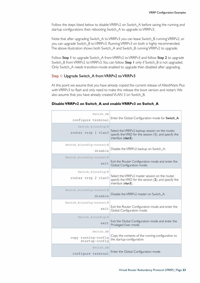
Follow the steps listed below to disableVRRPv2 on Switch_A before saving the running andstartup configurations then rebooting Switch_A to upgrade toVRRPv3.
Note that after upgrading Switch_A toVRRPv3 you can leave Switch_B runningVRRPv2, oryou can upgrade Switch_B toVRRPv3. RunningVRRPv3 on both is highly recommended.The above illustration shows both Switch_A and Switch_B runningVRRPv2 to upgrade.
Follow Step 1 to upgrade Switch_A fromVRRPv2 toVRRPv3 and follow Step 2 to upgradeSwitch_B fromVRRPv2 toVRRPv3.You can follow Step 1 only if Switch_B is not upgraded.Only Switch_A needs transition-mode enabled to upgrade then disabled after upgrading.
Step 1: Upgrade Switch_A from VRRPv2 to VRRPv3
At this point we assume that you have already copied the current release of AlliedWare PluswithVRRPv3 to flash and only need to make this release the boot version and restart. Wealso assume that you have already createdVLAN 3 on Switch_B.
Disable VRRPv2 on Switch_A and enable VRRPv3 on Switch_A
Switch_A#configure terminal Enter the Global Configuration mode for Switch_A.
Switch_A(config)#router vrrp 1 vlan3 Select theVRRPv2 backup session on the router,
specify theVRID for the session (1), and specify theinterface (vlan3).
Switch_A(config-router)#disable Disable theVRRPv2 backup on Switch_A.
Switch_A(config-router)#exit Exit the Router Configuration mode and enter the
Global Configuration mode.
Switch_A(config)#router vrrp 2 vlan3 Select theVRRPv2 master session on the router,
specify theVRID for the session (2), and specify theinterface (vlan3).
Switch_A(config-router)#disable Disable theVRRPv2 master on Switch_A.
Switch_A(config-router)#exit Exit the Router Configuration mode and enter the
Global Configuration mode.
Switch_A(config)#exit Exit the Global Configuration mode and enter the
Privileged Exec mode.
Switch_A#copy running-config
startup-configCopy the contents of the running-configuration tothe startup-configuration.
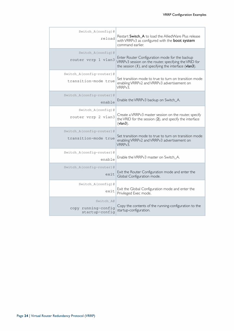
Switch_A#configure terminal Enter the Global Configuration mode.
Virtual Router Redundancy Protocol (VRRP) | Page 23
VRRP Configuration Examples
Switch_A(config)#reload Restart Switch_A to load the AlliedWare Plus release
withVRRPv3 as configured with the boot systemcommand earlier.
Switch_A(config)#router vrrp 1 vlan3 Enter Router Configuration mode for the backup
VRRPv3 session on the router, specifying theVRID forthe session (1), and specifying the interface (vlan3).
Switch_A(config-router)#transition-mode true Set transition mode to true to turn on transition mode
enablingVRRPv2 andVRRPv3 advertisement onVRRPv3.
Switch_A(config-router)#enable Enable theVRRPv3 backup on Switch_A.
Switch_A(config)#router vrrp 2 vlan3 Create aVRRPv3 master session on the router, specify
theVRID for the session (2), and specify the interface(vlan3).
Switch_A(config-router)#transition-mode true Set transition mode to true to turn on transition mode
enablingVRRPv2 andVRRPv3 advertisement onVRRPv3.
Switch_A(config-router)#enable Enable theVRRPv3 master on Switch_A.
Switch_A(config-router)#exit Exit the Router Configuration mode and enter the
Global Configuration mode.
Switch_A(config)#exit Exit the Global Configuration mode and enter the
Privileged Exec mode.
Switch_A#copy running-config
startup-configCopy the contents of the running-configuration to thestartup-configuration.
Page 24 | Virtual Router Redundancy Protocol (VRRP)
VRRP Configuration Examples
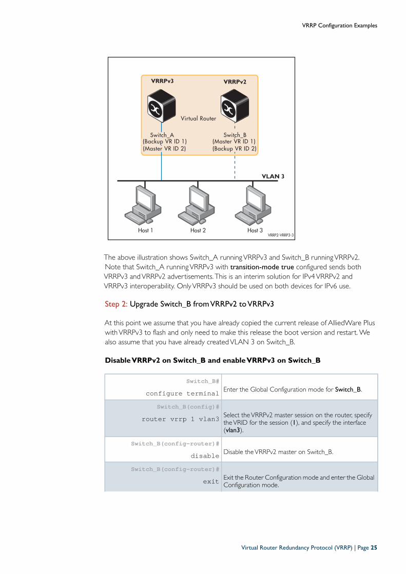
The above illustration shows Switch_A runningVRRPv3 and Switch_B runningVRRPv2.Note that Switch_A runningVRRPv3 with transition-mode true configured sends bothVRRPv3 andVRRPv2 advertisements. This is an interim solution for IPv4VRRPv2 andVRRPv3 interoperability. OnlyVRRPv3 should be used on both devices for IPv6 use.
Step 2: Upgrade Switch_B from VRRPv2 to VRRPv3
At this point we assume that you have already copied the current release of AlliedWare PluswithVRRPv3 to flash and only need to make this release the boot version and restart. Wealso assume that you have already createdVLAN 3 on Switch_B.
Disable VRRPv2 on Switch_B and enable VRRPv3 on Switch_B
Switch_B#configure terminal Enter the Global Configuration mode for Switch_B.
Switch_B(config)#router vrrp 1 vlan3 Select theVRRPv2 master session on the router, specify
theVRID for the session (1), and specify the interface(vlan3).
Switch_B(config-router)#disable Disable theVRRPv2 master on Switch_B.
Switch_B(config-router)#exit Exit the Router Configuration mode and enter the Global
Configuration mode.
Host 1 Host 2 Host 3VRRP2-VRRP3-3
Virtual Router
Switch_B Switch_A(Backup VR ID 1) (Master VR ID 1)
VLAN 3
(Master VR ID 2) (Backup VR ID 2)
VRRPv3 VRRPv2
Virtual Router Redundancy Protocol (VRRP) | Page 25
VRRP Configuration Examples
Switch_B(config)#router vrrp 2 vlan3 Select theVRRPv2 backup session on the router, specify
theVRID for the session (2), and specify the interface(vlan3).
Switch_B(config-router)#disable Disable theVRRPv2 backup on Switch_B.
Switch_B(config-router)#exit Exit the Router Configuration mode and enter the Global
Configuration mode.
Switch_B(config)#exit Exit the Global Configuration mode and enter the
Privileged Exec mode.
Switch_B#copy running-config
startup-configCopy the contents of the running-configuration to thestartup-configuration.
Switch_B#configure terminal Enter the Global Configuration mode.
Switch_B(config)#reload Restart Switch_A to load the AlliedWare Plus release
withVRRPv3 as configured with the boot systemcommand earlier.
Switch_B(config)#router vrrp 1 vlan3 Enter Router Configuration mode for the masterVRRPv3
session on the router, specifying theVRID for the session(1), and specifying the interface (vlan3).
Switch_B(config-router)#enable Enable theVRRPv3 master on Switch_B.
Switch_B(config-router)#exit Exit the Router Configuration mode and enter the Global
Configuration mode.
Switch_B(config)#router vrrp 2 vlan3 Enter Router Configuration mode for the backupVRRPv3
session on the router, specifying theVRID for the session(2), and specifying the interface (vlan3).
Switch_B(config-router)#enable Enable theVRRPv3 backup on Switch_B.
Switch_B(config-router)#exit Exit the Router Configuration mode and enter the Global
Configuration mode.
Switch_B(config)#exit Exit the Global Configuration mode and enter the
Privileged Exec mode.
Switch_B#copy running-config
startup-configCopy the contents of the running-configuration to thestartup-configuration.
Page 26 | Virtual Router Redundancy Protocol (VRRP)
VRRP Configuration Examples
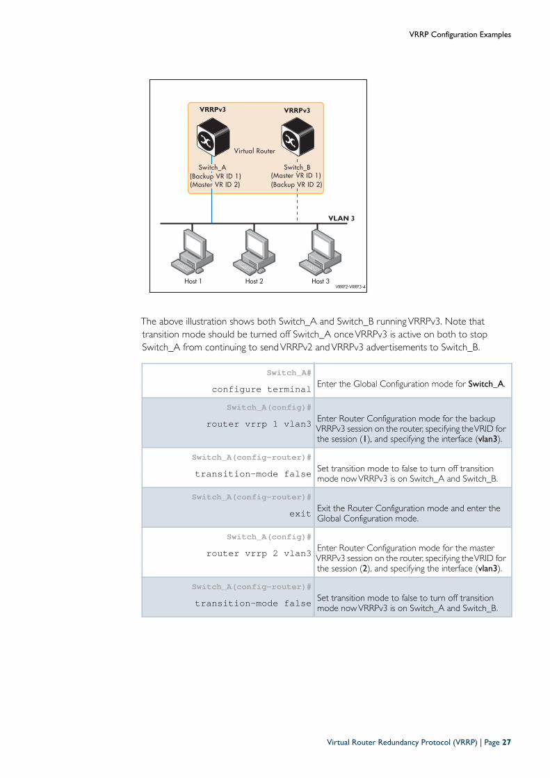
The above illustration shows both Switch_A and Switch_B runningVRRPv3. Note thattransition mode should be turned off Switch_A onceVRRPv3 is active on both to stopSwitch_A from continuing to sendVRRPv2 andVRRPv3 advertisements to Switch_B.
Switch_A#configure terminal Enter the Global Configuration mode for Switch_A.
Switch_A(config)#router vrrp 1 vlan3 Enter Router Configuration mode for the backup
VRRPv3 session on the router, specifying theVRID forthe session (1), and specifying the interface (vlan3).
Switch_A(config-router)#transition-mode false Set transition mode to false to turn off transition
mode nowVRRPv3 is on Switch_A and Switch_B.
Switch_A(config-router)#exit Exit the Router Configuration mode and enter the
Global Configuration mode.
Switch_A(config)#router vrrp 2 vlan3 Enter Router Configuration mode for the master
VRRPv3 session on the router, specifying theVRID forthe session (2), and specifying the interface (vlan3).
Switch_A(config-router)#transition-mode false Set transition mode to false to turn off transition
mode nowVRRPv3 is on Switch_A and Switch_B.
Host 1 Host 2 Host 3VRRP2-VRRP3-4
Virtual Router
Switch_B Switch_A(Backup VR ID 1) (Master VR ID 1)
VLAN 3
(Master VR ID 2) (Backup VR ID 2)
VRRPv3 VRRPv3
Virtual Router Redundancy Protocol (VRRP) | Page 27
VRRP Configuration Examples
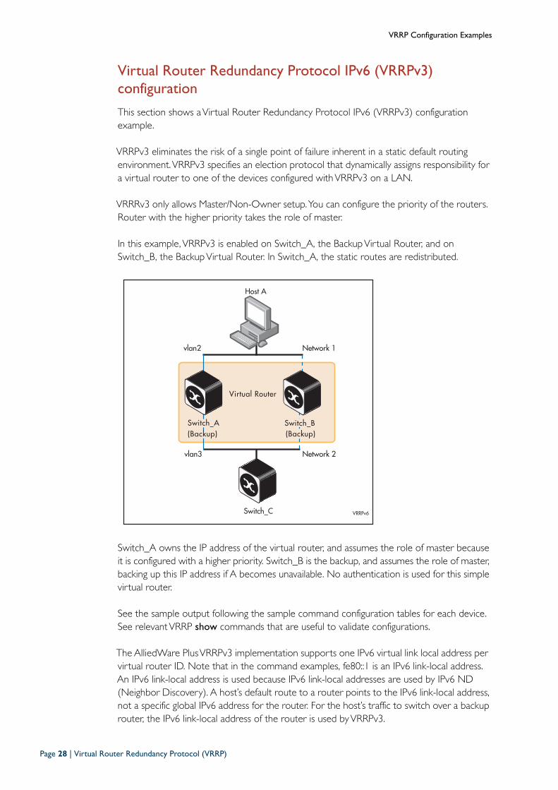
Virtual Router Redundancy Protocol IPv6 (VRRPv3) configuration
This section shows aVirtual Router Redundancy Protocol IPv6 (VRRPv3) configurationexample.
VRRPv3 eliminates the risk of a single point of failure inherent in a static default routingenvironment.VRRPv3 specifies an election protocol that dynamically assigns responsibility fora virtual router to one of the devices configured withVRRPv3 on a LAN.
VRRRv3 only allows Master/Non-Owner setup.You can configure the priority of the routers.Router with the higher priority takes the role of master.
In this example, VRRPv3 is enabled on Switch_A, the BackupVirtual Router, and onSwitch_B, the BackupVirtual Router. In Switch_A, the static routes are redistributed.
Switch_A owns the IP address of the virtual router, and assumes the role of master becauseit is configured with a higher priority. Switch_B is the backup, and assumes the role of master,backing up this IP address if A becomes unavailable. No authentication is used for this simplevirtual router.
See the sample output following the sample command configuration tables for each device.See relevantVRRP show commands that are useful to validate configurations.
The AlliedWare PlusVRRPv3 implementation supports one IPv6 virtual link local address pervirtual router ID. Note that in the command examples, fe80::1 is an IPv6 link-local address.An IPv6 link-local address is used because IPv6 link-local addresses are used by IPv6 ND(Neighbor Discovery). A host’s default route to a router points to the IPv6 link-local address,not a specific global IPv6 address for the router. For the host’s traffic to switch over a backuprouter, the IPv6 link-local address of the router is used byVRRPv3.
Host A
VRRPv6
Virtual Router
Switch_BSwitch_A(Backup) (Backup)
Switch_C
vlan3
vlan2
Network 2
Network 1
Page 28 | Virtual Router Redundancy Protocol (VRRP)

VRRP Configuration Examples
Step 1: Configure Switch_A (Backup Virtual Router)
At this point we assume that you have already createdVLAN 2 andVLAN 3 on Switch_A.
a. Configure IPv6 addresses on VLAN 2 and VLAN 3
b. Create the Backup Virtual Router on Switch_A
awplus#configure terminal Enter the Global Configuration mode.
awplus(config)#hostname Switch_A Assign a host name to Switch_A.
Switch_A(config)#interface vlan2 Specify the interface (vlan2) that will
participate in virtual routing to firstconfigure an IP address for vlan2.
Switch_A(config-if)#ipv6 address 2001:db8:2::2/64 Specify the IPv6 address and mask for
interface vlan2.
Switch_A(config-if)#exit Return to Global Configuration mode.
Switch_A(config)#interface vlan3 Specify the interface (vlan3) that will
participate in virtual routing to firstconfigure an IP address for vlan3.
Switch_A(config-if)#ipv6 address 2001:db8:3::2/64 Specify the IPv6 address and mask for
interface vlan3.
Switch_A(config-if)#exit Return to Global Configuration mode.
Switch_A(config)#router ipv6 vrrp 1 vlan2 Create a newVRRPv3 session on Switch_A,
specify theVRID for the session, and specify theinterface (vlan2) that will participate in virtualrouting.
Switch_A(config-router)#virtual-ipv6 fe80::1 backup Set the virtual IP address for theVRRPv3
session. Define the default state of theVRRPv3router within the virtual router.Note that fe80::1 is an IPv6 link-local address.The AlliedWare PlusVRRPv3 implementationsupports one IPv6 virtual link local address pervirtual router ID.See the Usage note for the virtual-ipv6command for implementation informationabout link-local addresses in AlliedWare Plus.
Virtual Router Redundancy Protocol (VRRP) | Page 29
VRRP Configuration Examples
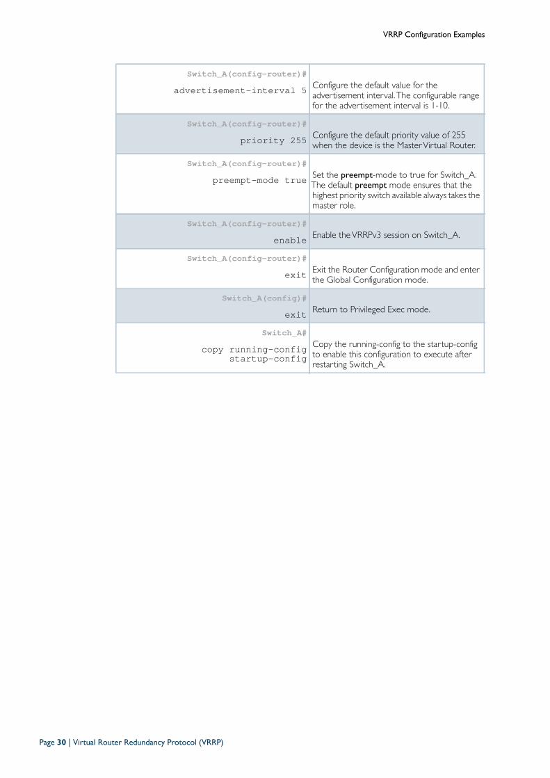
Switch_A(config-router)#advertisement-interval 5 Configure the default value for the
advertisement interval. The configurable rangefor the advertisement interval is 1-10.
Switch_A(config-router)#priority 255 Configure the default priority value of 255
when the device is the MasterVirtual Router.
Switch_A(config-router)#preempt-mode true Set the preempt-mode to true for Switch_A.
The default preempt mode ensures that thehighest priority switch available always takes themaster role.
Switch_A(config-router)#enable Enable theVRRPv3 session on Switch_A.
Switch_A(config-router)#exit Exit the Router Configuration mode and enter
the Global Configuration mode.
Switch_A(config)#exit Return to Privileged Exec mode.
Switch_A#copy running-config
startup-configCopy the running-config to the startup-configto enable this configuration to execute afterrestarting Switch_A.
Page 30 | Virtual Router Redundancy Protocol (VRRP)
VRRP Configuration Examples
Step 2: Configure Switch_B (Backup Virtual Router)
At this point we assume that you have already createdVLAN 2 andVLAN 3 on Switch_B.
a. Configure IPv6 addresses on VLAN 2 and VLAN 3
b. Create the Backup Virtual Router on Switch_B
awplus#configure terminal Enter the Global Configuration mode.
awplus(config)#hostname Switch_B Assign a host name to Switch_B.
Switch_B(config)#interface vlan2 Specify the interface (vlan2) that will participate
in virtual routing to first configure an IP addressfor vlan2.
Switch_B(config-if)#ipv6 address 2001:db8:2::3/
64Specify the IPv6 address and mask for interfacevlan2.
Switch_B(config-if)#exit Return to Global Configuration mode.
Switch_B(config)#interface vlan3 Specify the interface (vlan3) that will participate
in virtual routing to first configure an IP addressfor vlan3.
Switch_B(config-if)#ipv6 address 2001:db8:3::3/
64Specify the IPv6 address and mask for interfacevlan3.
Switch_B(config-if)#exit Return to Global Configuration mode.
Switch_B(config)#router ipv6 vrrp 1 vlan2 Create a newVRRPv3 session on Switch_B,
specify theVRID for the session, and specifythe interface (vlan2) that will participate invirtual routing.
Switch_B(config-router)#virtual-ipv6 fe80::1 backup Set the virtual IP address for theVRRP session.
Define the default state of theVRRP routerwithin the virtual router.Note that fe80::1 is an IPv6 link-local address.The AlliedWare PlusVRRPv3 implementationsupports one IPv6 virtual link local address pervirtual router ID.See the Usage note for the virtual-ipv6command for implementation informationabout link-local addresses in AlliedWare Plus.
Virtual Router Redundancy Protocol (VRRP) | Page 31
VRRP Configuration Examples
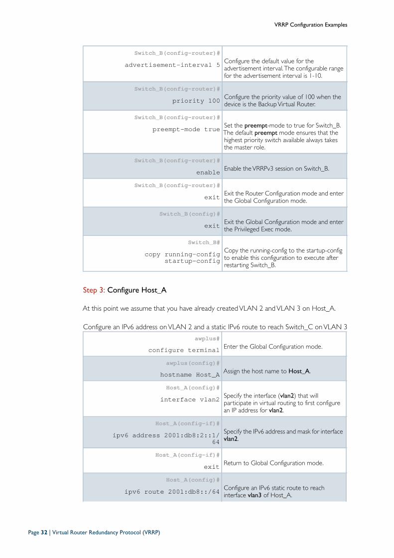
Step 3: Configure Host_A
At this point we assume that you have already createdVLAN 2 andVLAN 3 on Host_A.
Configure an IPv6 address onVLAN 2 and a static IPv6 route to reach Switch_C onVLAN 3
Switch_B(config-router)#advertisement-interval 5 Configure the default value for the
advertisement interval.The configurable rangefor the advertisement interval is 1-10.
Switch_B(config-router)#priority 100 Configure the priority value of 100 when the
device is the BackupVirtual Router.
Switch_B(config-router)#preempt-mode true Set the preempt-mode to true for Switch_B.
The default preempt mode ensures that thehighest priority switch available always takesthe master role.
Switch_B(config-router)#enable Enable theVRRPv3 session on Switch_B.
Switch_B(config-router)#exit Exit the Router Configuration mode and enter
the Global Configuration mode.
Switch_B(config)#exit Exit the Global Configuration mode and enter
the Privileged Exec mode.
Switch_B#copy running-config
startup-configCopy the running-config to the startup-configto enable this configuration to execute afterrestarting Switch_B.
awplus#configure terminal Enter the Global Configuration mode.
awplus(config)#hostname Host_A Assign the host name to Host_A.
Host_A(config)#interface vlan2 Specify the interface (vlan2) that will
participate in virtual routing to first configurean IP address for vlan2.
Host_A(config-if)#ipv6 address 2001:db8:2::1/
64Specify the IPv6 address and mask for interfacevlan2.
Host_A(config-if)#exit Return to Global Configuration mode.
Host_A(config)#ipv6 route 2001:db8::/64 Configure an IPv6 static route to reach
interface vlan3 of Host_A.
Page 32 | Virtual Router Redundancy Protocol (VRRP)
VRRP Configuration Examples
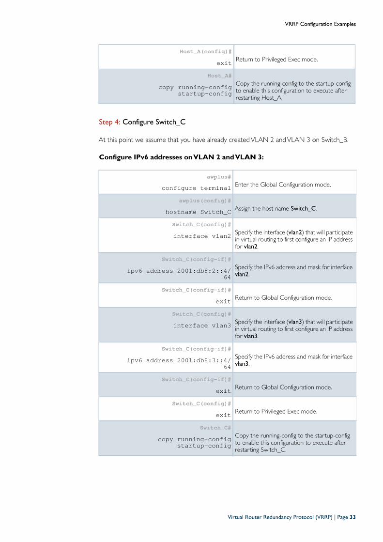
Step 4: Configure Switch_C
At this point we assume that you have already createdVLAN 2 andVLAN 3 on Switch_B.
Configure IPv6 addresses on VLAN 2 and VLAN 3:
Host_A(config)#exit Return to Privileged Exec mode.
Host_A#copy running-config
startup-configCopy the running-config to the startup-configto enable this configuration to execute afterrestarting Host_A.
awplus#configure terminal Enter the Global Configuration mode.
awplus(config)#hostname Switch_C Assign the host name Switch_C .
Switch_C(config)#interface vlan2 Specify the interface (vlan2) that will participate
in virtual routing to first configure an IP addressfor vlan2.
Switch_C(config-if)#ipv6 address 2001:db8:2::4/
64Specify the IPv6 address and mask for interfacevlan2.
Switch_C(config-if)#exit Return to Global Configuration mode.
Switch_C(config)#interface vlan3 Specify the interface (vlan3) that will participate
in virtual routing to first configure an IP addressfor vlan3.
Switch_C(config-if)#ipv6 address 2001:db8:3::4/
64Specify the IPv6 address and mask for interfacevlan3.
Switch_C(config-if)#exit Return to Global Configuration mode.
Switch_C(config)#exit Return to Privileged Exec mode.
Switch_C#copy running-config
startup-configCopy the running-config to the startup-configto enable this configuration to execute afterrestarting Switch_C.
Virtual Router Redundancy Protocol (VRRP) | Page 33
VRRP Configuration Examples
VRRPv3 configuration validation commands and output
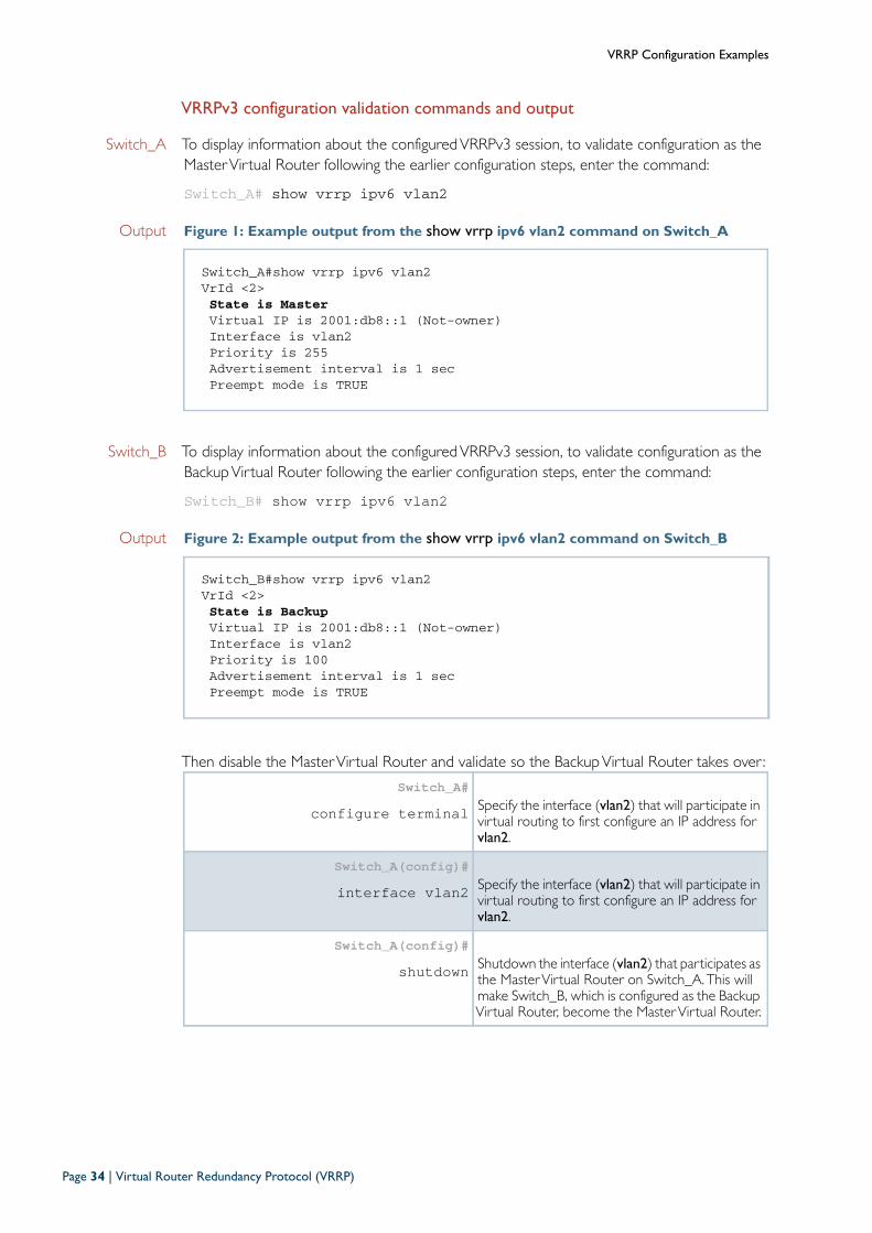
Switch_A To display information about the configuredVRRPv3 session, to validate configuration as theMasterVirtual Router following the earlier configuration steps, enter the command:
Switch_A# show vrrp ipv6 vlan2
Output Figure 1: Example output from the show vrrp ipv6 vlan2 command on Switch_A
Switch_B To display information about the configuredVRRPv3 session, to validate configuration as theBackupVirtual Router following the earlier configuration steps, enter the command:
Switch_B# show vrrp ipv6 vlan2
Output Figure 2: Example output from the show vrrp ipv6 vlan2 command on Switch_B
Then disable the MasterVirtual Router and validate so the BackupVirtual Router takes over:
Switch_A#show vrrp ipv6 vlan2VrId <2>State is MasterVirtual IP is 2001:db8::1 (Not-owner)Interface is vlan2Priority is 255Advertisement interval is 1 secPreempt mode is TRUE
Switch_B#show vrrp ipv6 vlan2VrId <2>State is BackupVirtual IP is 2001:db8::1 (Not-owner)Interface is vlan2Priority is 100Advertisement interval is 1 secPreempt mode is TRUE
Switch_A#configure terminal Specify the interface (vlan2) that will participate in
virtual routing to first configure an IP address forvlan2.
Switch_A(config)#interface vlan2 Specify the interface (vlan2) that will participate in
virtual routing to first configure an IP address forvlan2.
Switch_A(config)#shutdown Shutdown the interface (vlan2) that participates as
the MasterVirtual Router on Switch_A.This willmake Switch_B, which is configured as the BackupVirtual Router, become the MasterVirtual Router.
Page 34 | Virtual Router Redundancy Protocol (VRRP)
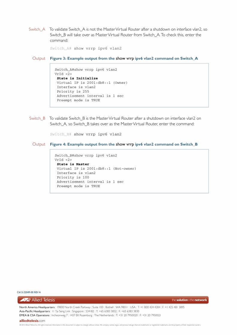
Switch_A To validate Switch_A is not the MasterVirtual Router after a shutdown on interface vlan2, soSwitch_B will take over as MasterVirtual Router from Switch_A.To check this, enter thecommand:
Switch_A# show vrrp ipv6 vlan2
Output Figure 3: Example output from the show vrrp ipv6 vlan2 command on Switch_A
Switch_B To validate Switch_B is the MasterVirtual Router after a shutdown on interface vlan2 onSwitch_A, so Switch_B takes over as the MasterVirtual Router, enter the command:
Switch_B# show vrrp ipv6 vlan2
Output Figure 4: Example output from the show vrrp ipv6 vlan2 command on Switch_B
Switch_A#show vrrp ipv6 vlan2VrId <2>State is InitializeVirtual IP is 2001:db8::1 (Owner)Interface is vlan2Priority is 255Advertisement interval is 1 secPreempt mode is TRUE
Switch_B#show vrrp ipv6 vlan2VrId <2>State is MasterVirtual IP is 2001:db8::1 (Not-owner)Interface is vlan2Priority is 100Advertisement interval is 1 secPreempt mode is TRUE
C613-22049-00 REV A
North America Headquarters | 19800 North Creek Parkway | Suite 100 | Bothell | WA 98011 | USA | T: +1 800 424 4284 | F: +1 425 481 3895
Asia-Pacifi c Headquarters | 11 Tai Seng Link | Singapore | 534182 | T: +65 6383 3832 | F: +65 6383 3830
EMEA & CSA Operations | Incheonweg 7 | 1437 EK Rozenburg | The Netherlands | T: +31 20 7950020 | F: +31 20 7950021
alliedtelesis.com© 2015 Allied Telesis Inc. All rights reserved. Information in this document is subject to change without notice. All company names, logos, and product designs that are trademarks or registered trademarks are the property of their respective owners.