con ed high tension_eo-2022 (1)
TRANSCRIPT
8/10/2019 Con Ed High Tension_EO-2022 (1)
http://slidepdf.com/reader/full/con-ed-high-tensioneo-2022-1 1/81
CONSOLIDATED EDISON CO. OF NEW YORK, INC.4 IRVING PLACE
NEW YORK, NY 10003
DISTRIBUTION ENGINEERING DEPARTMENTNETWORK SYSTEMS SECTION
SPECIFICATION EO-2022
REVISION 15
DECEMBER 2009
EFFECTIVE DATEDECEMBER 31, 2009
GENERAL SPECIFICATION FOR HIGH TENSION SERVICE
FIELD MANUAL No. 16, SECTION 4
TARGET AUDIENCE DISTRIBUTION ENGINEERINGENERGY SERVICESSYSTEM OPERATIONSREVENUE METERING
NESC REFERENCE 2002 ALL
Copyright Information 1966-2009 Consolidated Edison Co. of New York, Inc.Paper copies of procedures and instructions are uncontrolled and therefore may be outdated. Please consultDistribution Engineering Intranet Site Distribution Engineering or http://distribution for the current version prior to use.
Page 2/81
8/10/2019 Con Ed High Tension_EO-2022 (1)
http://slidepdf.com/reader/full/con-ed-high-tensioneo-2022-1 2/81
Specification Revision Rev Date EffectiveDate
Copyright Information Page 2/81
EO – 2022 15 12/31/2009 1966-2009 Consolidated Edison Co. of New York, Inc.
Filing Information Application and Design Manual No. 4
Paper copies of procedures and instructions are uncontrolled and therefore may be outdated. Please consult DistributionEngineering Intranet Site Distribution Engineering or http://distribution, for the current version prior to use.
TABLE OF CONTENTS
Paragraph Description
1.0 PURPOSE
2.0 APPLICATION
3.0 DEFINITIONS
3.1 Customer and Company3.2 Company Service Type and Voltage3.3 Customer Utilization Voltage
3.4 Contingencies3.5 Feeder Bands3.6 Primary Service Feeder Lineup3.7 Electrical Equipment Rooms3.8 Switchgear3.9 Switchgear Room3.10 Transformer Room3.11 Transformer Vault
4.0 GENERAL
4.1 Customer Data4.2 General & Technical Specifications4.3 Service Availability
5.0 RADIAL DESIGN CONFIGURATION
5.1 Radial Design5.2 Relay Protection5.3 Manual and Automatic Load Shifting
8/10/2019 Con Ed High Tension_EO-2022 (1)
http://slidepdf.com/reader/full/con-ed-high-tensioneo-2022-1 3/81
Specification Revision Rev Date EffectiveDate
Copyright Information Page 3/81
EO – 2022 15 12/31/2009 1966-2009 Consolidated Edison Co. of New York, Inc.
Filing Information Application and Design Manual No. 4
Paper copies of procedures and instructions are uncontrolled and therefore may be outdated. Please consult DistributionEngineering Intranet Site Distribution Engineering or http://distribution, for the current version prior to use.
TABLE OF CONTENTS
Paragraph Description
5.4 Automatic Transfer Eligibility5.5 Automatic Transfer Logic5.6 Automatic Transfer Time Delay5.7 Transfer of Customer Load Buses5.8 Manual Transfer and Retransfer5.9 Interlocking System Electrical Controls5.10 Grounding5.11 G&T Device and Ground Switch5.12 Emergency Generators
5.13 Remote Monitoring and Control
6.0 PARALLEL DESIGN CONFIGURATION
6.1 Parallel Design6.2 Relay Protection6.3 Grounding6.4 Emergency Generators6.5 Remote Monitoring and Control
7.0 SERVICE VAULTS AND COMPARTMENTS
7.1 Items for Review7.2 Electrical Equipment Rooms7.3 Power Transformers7.4 Environmental Issues7.4.1 Power Transformer Oil Containment7.5 Security Fence and Lighting
8/10/2019 Con Ed High Tension_EO-2022 (1)
http://slidepdf.com/reader/full/con-ed-high-tensioneo-2022-1 4/81
Specification Revision Rev Date EffectiveDate
Copyright Information Page 4/81
EO – 2022 15 12/31/2009 1966-2009 Consolidated Edison Co. of New York, Inc.
Filing Information Application and Design Manual No. 4
Paper copies of procedures and instructions are uncontrolled and therefore may be outdated. Please consult DistributionEngineering Intranet Site Distribution Engineering or http://distribution, for the current version prior to use.
TABLE OF CONTENTS
Paragraph Description
8.0 PRIMARY SERVICE FEEDERS
8.1 Underground Feeders8.2 Overhead Feeders8.3 Point of Entry8.4 Termination Cubicle8.5 Final Splice8.6 Company Feeder Extension8.7 Required Testing
9.0 REVENUE METERING
9.1 Radial and Parallel Installations9.2 Space for Meters9.3 Wiring and Connections
10.0 STANDARDS AND CODE REQUIREMENTS
11.0 DOCUMENTATION
11.1 Required Submittals11.2 Required Customer Information11.3 Load Data11.4 System Operation11.5 Vendor Data11.6 Design Changes11.7 Tests11.8 Number of Copies
8/10/2019 Con Ed High Tension_EO-2022 (1)
http://slidepdf.com/reader/full/con-ed-high-tensioneo-2022-1 5/81
Specification Revision Rev Date EffectiveDate
Copyright Information Page 5/81
EO – 2022 15 12/31/2009 1966-2009 Consolidated Edison Co. of New York, Inc.
Filing Information Application and Design Manual No. 4
Paper copies of procedures and instructions are uncontrolled and therefore may be outdated. Please consult DistributionEngineering Intranet Site Distribution Engineering or http://distribution, for the current version prior to use.
TABLE OF CONTENTS
Paragraph Description
12.0 MAINTENANCE AND INSPECTION
13.0 LIST OF REFERENCES
14.0 ATTACHMENTS
15.0 SPECIFICATION ACCEPTANCE
8/10/2019 Con Ed High Tension_EO-2022 (1)
http://slidepdf.com/reader/full/con-ed-high-tensioneo-2022-1 6/81
Specification Revision Rev Date EffectiveDate
Copyright Information Page 6/81
EO – 2022 15 12/31/2009 1966-2009 Consolidated Edison Co. of New York, Inc.
Filing Information Application and Design Manual No. 4
Paper copies of procedures and instructions are uncontrolled and therefore may be outdated. Please consult DistributionEngineering Intranet Site Distribution Engineering or http://distribution, for the current version prior to use.
GENERAL SPECIFICATION FOR HIGH TENSION SERVICE
.0 PURPOSE
The purpose of the General Specification is to provide the Consolidated Edison Company's generequirements for High Tension service and to outline the various types of High Tension Servicesavailable. The General Specification details the areas of responsibility for ownership, constructionalteration, operation and maintenance of equipment. The Company's detailed engineeringrequirements for the High Tension Service are given in the supplemental Technical SpecificationThe General and the Technical Specifications, with the appropriate support documents, compristhe Company's requirements for the Customer to obtain High Tension service. To be considered fHigh Tension service, which is a non-standard service, the customer must agree to all of therequirements contained herein.
2.0 APPLICATION
All Energy Service Departments and High Tension Customers.
3.0 DEFINITIONS
3.1 Customer and Company - For future reference throughout this specification, the ConsolidateEdison Company of New York, Inc. is referred to as the "Company". All reference to "Custom
shall refer to the owner of the installation as defined in the supplemental TechnicalSpecification.
3.2 Company Service Type and Voltage - High Tension Service is either Radial or Parallel. AllHigh Tension Service Customer’s are provided a primary nominal voltage of; 4 kV, 13 kV, 27 or 33 kV. The Con Edison Customer Service Representative will provide the actual servicevoltage on request. Billing will be at the appropriate High Tension rate in accordance with theprovisions of the Schedule for Electricity and the Requirements for Electric Service
Installations or other contract agreements. In all cases, the Customer provides primaryswitchgear and power transformers to isolate the Customer’s service from the Company syste
8/10/2019 Con Ed High Tension_EO-2022 (1)
http://slidepdf.com/reader/full/con-ed-high-tensioneo-2022-1 7/81
Specification Revision Rev Date EffectiveDate
Copyright Information Page 7/81
EO – 2022 15 12/31/2009 1966-2009 Consolidated Edison Co. of New York, Inc.
Filing Information Application and Design Manual No. 4
Paper copies of procedures and instructions are uncontrolled and therefore may be outdated. Please consult DistributionEngineering Intranet Site Distribution Engineering or http://distribution, for the current version prior to use.
The Customer’s utilization voltage is developed on the load side of the Customer owned powtransformers. If the utilization voltage is the same as the supplied voltage, then 1:1 isolationpower transformers will be required.
3.3 Customer Utilization Voltage - The Customer’s utilization voltage is based on the Customerequipment requirements. The Customer’s responsibility is to install equipment that will properoperate within the range of standard voltage deviations. The Customer’s responsibility includethe installation of protective devices that will protect against transient voltage excursions,harmonics, momentary voltage sags, and unbalances.
3.4 Contingencies - Each part of the Company's service territory has been categorized by thenumber of allowable coincidental feeder outages that can be tolerated without adverselyaffecting the character of the Customer's service. These outages are referred to as
contingencies . In a first contingency area, the Customer's installation must be designed fo
the loss of one primary service feeder. In a second cont ingency area, the Customer'sinstallation must be designed for the loss of two primary service feeders. Therefore, to ensurethe Customer's service configuration matches the Company's design criteria, the Customer isprovided a minimum of two primary service feeders in a first contingency area and a minimumthree primary service feeders in a second contingency area. During contingency operation, thdesign (capacity, configuration, relays, transformers, switchgear, etc.) of the customer’sinstallation must be such that the Customer’s entire maximum demand can be supplied withooverloading his equipment remaining on line in accordance with the electrical codes governinthe use of his equipment.
3.5 Feeder Bands - A “Feeder Band” is defined, in both first and second contingency design are
as two network feeders identified as primary service feeders supplying the customer’s htension service that are installed in a common duct bank, utility pole or equipment room. term feeder band is also applied to the customer’s primary feeder switchgear lineup (e.g., primary feeder switchgear lineups housed in one electrical equipment room.
3.6 Primary Service Feeder Switchgear Lineup - The Customer’s high tension equipmentincluding the pothead compartment, revenue service metering compartments and PrimaryService Feeder circuit breaker associated with and interconnected to a Company PrimaryService Feeder.
8/10/2019 Con Ed High Tension_EO-2022 (1)
http://slidepdf.com/reader/full/con-ed-high-tensioneo-2022-1 8/81
Specification Revision Rev Date EffectiveDate
Copyright Information Page 8/81
EO – 2022 15 12/31/2009 1966-2009 Consolidated Edison Co. of New York, Inc.
Filing Information Application and Design Manual No. 4
Paper copies of procedures and instructions are uncontrolled and therefore may be outdated. Please consult DistributionEngineering Intranet Site Distribution Engineering or http://distribution, for the current version prior to use.
3.7 Electrical Equipment Rooms - Electrical equipment rooms such as switchgear and transformrooms, battery rooms, etc shall only be used to house electrical equipment/systems with theexception of the non-electrical equipment/systems that serve the electrical room (e.g., ductwo
that provides ventilation for a transformer room).
3.8 Switchgear - Unless otherwise noted, all reference to primary switchgear equipment will bemedium voltage metal-clad circuit breakers or metal enclosed fused load-break disconnectswitches. However, due to the high fault currents on the Company’s system, fused load-breakdisconnect switch applications are limited to the 4 kV supply system and for certain applicatioin the 13 kV areas in Staten Island and Westchester.
3.9 Switchgear Room - An electrical equipment room located in the customer’s facility whichhouses the customer’s primary distribution switchgear and associated electrical equipment.
3.10 Transformer Room – An electrical equipment room located in the Customer’s facility dedicatto housing their dry-type power transformer.
3.11 Transformer Vault – An unattended isolated enclosure or structure housing the customer’sliquid-filled power transformer.
4.0 GENERAL
4.1 Customer Data - Based on the Customer’s submitted data, the Company will review its facilitand recommend the type of service which can be installed. Where a choice is given, theCustomer shall select one of the alternatives provided by the Company. The Company's
decision on the number of supply feeders will be based on the Customer's load requirement,contingency category, supply feeder availability, feeder loading and other pertinent factors. TCustomer shall review the Company’s EO-2022 General and Technical Specification requirements to assist in the design of the High Tension service. The Customer shall advise tCompany of any anticipated Customer load changes so that the Company can reevaluate theadequacy of its distribution supply system and Customer’s primary service feeder cables. If awhen the customer’s load increases, then the customer must reevaluate the capacity of hisequipment to insure that it can operate within the limits specified in the governing electricalcodes during both normal and the specified contingency conditions for the location.
8/10/2019 Con Ed High Tension_EO-2022 (1)
http://slidepdf.com/reader/full/con-ed-high-tensioneo-2022-1 9/81
Specification Revision Rev Date EffectiveDate
Copyright Information Page 9/81
EO – 2022 15 12/31/2009 1966-2009 Consolidated Edison Co. of New York, Inc.
Filing Information Application and Design Manual No. 4
Paper copies of procedures and instructions are uncontrolled and therefore may be outdated. Please consult DistributionEngineering Intranet Site Distribution Engineering or http://distribution, for the current version prior to use.
4.2 General & Technical Specifications - Upon finalizing the selection of the High Tension serv
design, the Company will prepare a site specific Technical Specification (with a DE referennumber) and support document(s). The General Specification and the site specific Technic
Specification shall be used by the Customer in the design of the High Tension serviceinstallation. It is highly recommended that the Customer incorporates the latest revision of theentire EO-2022 specification in his bid, purchasing and design specification packages. Whenthe Technical Specification is finalized it shall be signed by the Customer and Company’srepresentatives.
4.3 Service Availability - Recommendations and requirements outlined in the Companyspecifications and/or project documents shall apply to the specific location and load. At otherlocations or for other load requirements, a service with similar characteristics may not beavailable and different requirements may be imposed.
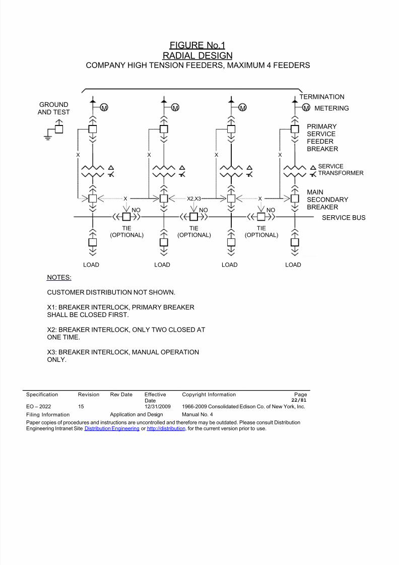
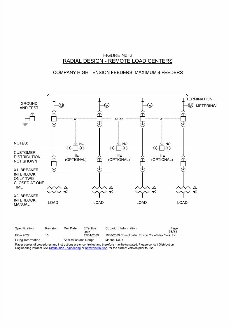
5.0 RADIAL DESIGN CONFIGURATION - (See Figures 1 & 2)
5.1 Radial Design - The Radial type design is permitted for installations located in first contingendesign areas. A Radial type Customer accepts primary service feeders at a Customer ownedproperty line manhole and terminates the primary service feeders at a Customer owned primaservice feeder disconnecting device. This type of Customer can tolerate a feeder outage durinloss of a primary service feeder, interruption during transfer, autotransfer or a Customercomponent failure (e.g., power transformer, primary service feeder breaker, etc.). The outageduration will be a function of the time to repair or replace the failed component or the time theCompany requires to restore the service.
5.2 Relay Protection - The Customer shall meet the Company’s relay protection requiremewhich protect the Company’s distribution system and the Customer’s facility. The Customer sinstall and maintain necessary equipment to:
• Automatically trip the primary service feeder circuit breaker if the current and voltagedeviates to an extent that would affect the Customer’s operating system or theCompany’s distribution system.
• Prevent energizing a de-energized Company primary service feeder.
8/10/2019 Con Ed High Tension_EO-2022 (1)
http://slidepdf.com/reader/full/con-ed-high-tensioneo-2022-1 10/81
Specification Revision Rev Date EffectiveDate
Copyright Information Page 10/81
EO – 2022 15 12/31/2009 1966-2009 Consolidated Edison Co. of New York, Inc.
Filing Information Application and Design Manual No. 4
Paper copies of procedures and instructions are uncontrolled and therefore may be outdated. Please consult DistributionEngineering Intranet Site Distribution Engineering or http://distribution, for the current version prior to use.
• Coordinate with Company relay devices and to isolate all Customer faults on theCustomer premises.
Protective relay requirements are detailed in the Technical Specification.
5.3 Manual and Automatic Load Shifting - Manual load shifting of Customer'ssecondary bus loads from one primary service feeder to an alternate source of power suppl
will not be permitted without prior Company approval. Automatic load transfer, of emergencyload buses will be permitted for a loss of either primary service feeder or Customer equipmen
failure. These loads and the mode of transfer shall be defined in a Customer's SystemOperation Specification that is submitted to the Company. All load transfers shall be made
through an approved break before make transfer type system.
5.4 Automatic Transfer Eligib il ity - The Radial design allows for an automatic transfer of Custoload for a primary service feeder or component failure. This automatic transfer option is reservfor Customers with CRITICAL loads only (e.g., hospitals, public service installations, correctiofacilities, etc.).
5.5 Automatic Transfer Logic - The Customer shall provide protective relay devices in theautomatic transfer circuitry to inhibit a transfer of a faulted portion of the Customer’s system to
an alternate source. The controls shall incorporate a manually reset lockout relay (see theTechnical Specification for other engineering requirements).
5.6 Automatic Transfer Time Delay - Automatic transfer control shall include a timer to prevent
load transfer under transient system conditions.
5.7 Transfer of Customer Load Buses - Automatic and manual transfer of Customer load busesshall be arranged on a break before make basis to negate Customer paralleling of the primaservice feeders. The Customer shall provide a paralleling bypass key, which will be under theCompany's jurisdiction, for transfer of load during scheduled work and the return to normalsupply.
5.8 Manual Transfer and Retransfer - Manual load transfer and retransfer of buses throughnormally open bus tie switchgear is made under the jurisdiction of the Company's District
8/10/2019 Con Ed High Tension_EO-2022 (1)
http://slidepdf.com/reader/full/con-ed-high-tensioneo-2022-1 11/81
Specification Revision Rev Date EffectiveDate
Copyright Information Page 11/81
EO – 2022 15 12/31/2009 1966-2009 Consolidated Edison Co. of New York, Inc.
Filing Information Application and Design Manual No. 4
Paper copies of procedures and instructions are uncontrolled and therefore may be outdated. Please consult DistributionEngineering Intranet Site Distribution Engineering or http://distribution, for the current version prior to use.
Operator. Transfer of loads in excess of those already defined in the Customer’s OperatingSpecification must be approved by the Company prior to the transfer. All Customer internalfailures shall be repaired and tested satisfactorily prior to the return to service. The Custome
load shall be transferred back to its normal supply as soon as possible.
5.9 Interlocking System Electrical Contro ls - Customer’s who have been given permission to uremote control electrical interlock systems shall have the interlock contacts monitored at amanned control room. The alarms shall indicate any primary service feeder status change orcircuit transfer. The Customer shall maintain qualified operating personnel on a 24 hour, 7 daa week basis to report all alarms to the Company's District Operator. The notification shall bmade within one hour of the alarm and the Customer's operating personnel shall await theCompany’s District Operators instructions. To properly expedite the isolation and grounding the primary service feeder, the one hour maximum response time must be adhered to on a 2hour, 7 day a week basis. For delays beyond the Customer's control, the Customer must us
his best effort to respond to Company switching instructions as quickly as possible. If in theCompany's opinion, the Customer's response time is not appropriate, the right to use electricinterlocks will be withdrawn and mechanical interlocks will be required.
5.10 Grounding - The Customer shall provide and install a ground mat and loop system for substatiequipment grounding. The grounding system shall be designed as per industry standards to capable of carrying the available fault currents and to limit voltage gradients in the substationwithin acceptable step and touch potentials. The Customer shall also provide and installacceptable equipment for grounding each primary service feeder at the line side of the primadisconnecting device. In addition to the approved methods of grounding addressed in thisspecification, the Customer shall also provide OSHA approved ground studs on the line side
each disconnecting device and associated ground cables and hotstick.
5.11 G&T Device and Ground Switch - The Company requires the Customer to provide a meanfor grounding each of the Company’s primary service feeders. When drawout type circuitbreakers are used, a Ground and Test (G&T) device or a ground switch may be used forgrounding the primary service feeders. When a fused load-break disconnect switch is used the primary service feeder disconnect, a ground switch is required for each primary servicefeeder. The ground switch shall be located on the line side of the first disconnect device andshall be key interlocked with its associated primary service feeder disconnect device to ensuthe primary service feeder disconnect device is locked open prior to closing the ground switcThe ground switch shall be inhibited from closing if voltage is present on the primary service
8/10/2019 Con Ed High Tension_EO-2022 (1)
http://slidepdf.com/reader/full/con-ed-high-tensioneo-2022-1 12/81
Specification Revision Rev Date EffectiveDate
Copyright Information Page 12/81
EO – 2022 15 12/31/2009 1966-2009 Consolidated Edison Co. of New York, Inc.
Filing Information Application and Design Manual No. 4
Paper copies of procedures and instructions are uncontrolled and therefore may be outdated. Please consult DistributionEngineering Intranet Site Distribution Engineering or http://distribution, for the current version prior to use.
feeder. Interlocks shall also ensure the ground switch is locked open before the primary serfeeder disconnect can be closed. The ground and primary service feeder disconnect devicesshall be able to be in the open position simultaneously.
5.12 Emergency Generators - Customer's emergency generator(s) shall not be connected inparallel with the Company’s service either at the primary or secondary voltage levels. Inaddition, service takeoffs serving Customer switchboards shall not be paralleled. Where theCustomer switchboards require a backup source, a Company approved break before maketype Automatic Transfer Switch or suitable key interlocked circuit breakers shall be used.Under certain circumstances closed transition transfer of emergency generators will beconsidered as per Con Edison Specification EO-2134, Closed Transition Transfer From andTo Con Edison's Supply.
5.13 Remote Monitoring and Control - The Company reserves the right to install, at any time,
remote monitoring and control equipment on the Customer's primary service feederswitchgear.
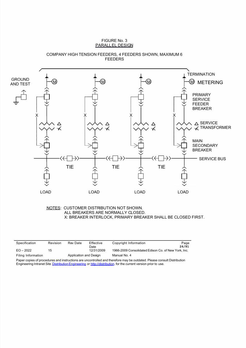
6.0 PARALLEL DESIGN CONFIGURATION - (See Figure 3)
6.1 Parallel Design - Parallel type design will be permitted for installations located in secondcontingency design areas. Parallel type design may be permitted for installations located in afirst contingency design area depending on the configuration of the primary service feeders.Consult with the Company to determine if parallel type design is permitted in a first contingenc
design area. Paralleling of the primary service feeders will only be permitted on the secondaside of the Customer’s power transformers. Circuit breakers are required as the primary serv
feeder and transformer main disconnect devices. The secondary connections of the Customepower transformer shall be connected in parallel through normally closed transformer secondmain and bus tie circuit breakers. Paralleling on the primary service feeders is not permitted.
6.2 Relay Protection - Relay protection shall be employed to protect the Company's system andCustomer's facility. The Company will comment on the Customer's relaying designs up to andincluding the Customer’s load bus and load takeoff circuits. In addition to the requirements fouin paragraph 5.2, reverse power and directional overcurrent relays shall be provided for eachprimary service feeder. Fault detection for backfeed into a phase to ground fault shall beprovided by either a zero sequence overvoltage relay connected to broken delta VT's or anover/under voltage relay connected to a phase to ground VT. Backup protection shall also be
8/10/2019 Con Ed High Tension_EO-2022 (1)
http://slidepdf.com/reader/full/con-ed-high-tensioneo-2022-1 13/81
Specification Revision Rev Date EffectiveDate
Copyright Information Page 13/81
EO – 2022 15 12/31/2009 1966-2009 Consolidated Edison Co. of New York, Inc.
Filing Information Application and Design Manual No. 4
Paper copies of procedures and instructions are uncontrolled and therefore may be outdated. Please consult DistributionEngineering Intranet Site Distribution Engineering or http://distribution, for the current version prior to use.
required (see the Technical Specification for additional relay protection requirements). Allprotective relays that operate for faults in the Customer’s equipment shall open the associateddisconnect device via a manually reset lockout relay. Remotely alarmed trip circuit monitoring
relays are required for the main power transformer primary and secondary circuit breakers, butie circuit breakers and the associated lockout relays that trip these circuit breakers. Monitorirelays shall be connected to the end of the trip ladder so that trip contact wiring will bemonitored.
6.3 Grounding - See paragraphs 5.10 and 5.11.
6.4 Emergency Generators - See paragraph 5.12.
6.5 Remote Monitoring and Control - See paragraph 5.13.
7.0 SERVICE VAULTS AND COMPARTMENTS
7.1 Items for Review - Customer shall furnish all electrical and site drawings, diagrams,specifications and Bill of Materials required to evaluate the complete electrical serviceinstallation. This shall include, but not limited to; manholes, feeder cables, splices, circuitbreakers, fused load-break switches, power and instrument transformers, disconnects, grounand transfer switches, buses, power transformer vaults and oil containment systems, relays aassociated devices, fuses, batteries and battery chargers, etc.
7.2 Electrical Equipment Rooms - Electrical equipment rooms such as switchgear and transformrooms, vaults, battery rooms, etc shall only be used to house electrical equipment/systems wi
the exception of the non-electrical equipment/systems that serve the electrical room (e.g.,ductwork that provides ventilation for a transformer room). Equipment and/or systems that seother purposes shall not be located within or be allowed to pass through these spaces. Thisincludes ductwork, hydronic heating/cooling piping, plumbing systems, roof drainage systemsetc. Electrical equipment rooms shall be adequate in size and layout such that all electricalequipment components such as transformers and medium voltage switchgear can beconveniently accessed for inspection and/or maintenance and can be conveniently removed frepair or replacement. All clearances required by the code and recommended by equipmentmanufacturers shall be provided. Each electrical equipment room shall be accessible from anegress corridor and, where appropriate, from the exterior of the building as well. Access toequipment rooms shall not be provided through other spaces such as restrooms, offices, etc.
8/10/2019 Con Ed High Tension_EO-2022 (1)
http://slidepdf.com/reader/full/con-ed-high-tensioneo-2022-1 14/81
Specification Revision Rev Date EffectiveDate
Copyright Information Page 14/81
EO – 2022 15 12/31/2009 1966-2009 Consolidated Edison Co. of New York, Inc.
Filing Information Application and Design Manual No. 4
Paper copies of procedures and instructions are uncontrolled and therefore may be outdated. Please consult DistributionEngineering Intranet Site Distribution Engineering or http://distribution, for the current version prior to use.
shall not be necessary to travel through a vulnerable finished area or a functioning occupiedarea in order to reach an equipment room. Electrical equipment room doors shall open outwaand shall be equipped with locks and accessible only to qualified personnel. Doors shall be
equipped with a quick release mechanism with a full width actuator (i.e., panic bar) on the insof the door and shall be capable of opening the door from the inside even if locked. Custometransformer vaults, transformer rooms, equipment and switchgear equipment areas shall be fof debris and shall incorporate Company safety design standards.
7.2.1 Two primary feeder service switchgear line-ups may be housed in one electricalequipment room provided the spacing between the primary feeder service switchgearlineups is at least ten (10) feet.
7.3 Power Transformers –
7.3.1 Liquid filled power transformers –
7.3.1.1 Liquid-filled power transformers are permitted for all voltage levels. Oil typepower transformers are limited to outdoor installations. Non-flammable liquid-filled power transformers may be installed indoors.
7.3.1.2 The Customer shall provide Fire/Blast walls for all liquid-filled transformerinstallations between outdoor liquid-filled power transformers and adjacent powtransformers, equipment or building structures, as per code.
7.3.2 Dry-Type Power Transformers –
7.3.2.1 Company approved dry type power transformers, will be permitted as primaryservice feeder power transformers for indoor installations. Company approveddry type transformers shall have primary and secondary coils vacuum cast inepoxy resin, utilizing step-lap mitered cruciform core construction. Customerschoosing to use dry type power transformers shall submit the appropriatedocumentation to the Company for approval.
7.3.2.2 No more than two dry type power transformers shall be installed in onetransformer room. Transformer rooms housing dry type transformers shall beconstructed of concrete block or reinforced concrete two (2) hour fire rated wa
8/10/2019 Con Ed High Tension_EO-2022 (1)
http://slidepdf.com/reader/full/con-ed-high-tensioneo-2022-1 15/81
Specification Revision Rev Date EffectiveDate
Copyright Information Page 15/81
EO – 2022 15 12/31/2009 1966-2009 Consolidated Edison Co. of New York, Inc.
Filing Information Application and Design Manual No. 4
Paper copies of procedures and instructions are uncontrolled and therefore may be outdated. Please consult DistributionEngineering Intranet Site Distribution Engineering or http://distribution, for the current version prior to use.
For transformer rooms where the distance between transformers or betweentransformers and any associated electrical equipment is less than ten (10) feefirewalls shall be required between the dry type power transformers and betwe
the transformers and such adjacent equipment.
7.3.2.3 All power transformers shall comply with the BIL ratings listed in thisspecification. Note: Equipment BIL ratings shall be without the use of surgearresters.
7.4 Environmental Issues
7.4.1 Power Transformer Oil Containment - Liquid filled power transformers require an oilcontainment system in event of a spill or a leak. An approved oil containment system (catch basin) and an approved drainage method shall be employed to prevent oil spillag
into a waterway, sewer system or the ground. The Company will review the Customer’sdesign to determine whether the Customer’s system is in compliance with the Companenvironmental requirements.
7.5 Security Fence and Lighting - Security fencing and lighting shall be provided for outdoorswitchgear, power transformers and electrical equipment.
8.0 PRIMARY SERVICE FEEDERS
8.1 Underground Feeders - For Customers supplied via underground feeders, the Company wilsupply and install primary service feeder cables up to the Customer’s approved property line
manhole. The property line manhole is provided and installed by the Customer and isconveniently located at the Customer's property line. A separate property line manhole isrequired for every two primary supply feeders.
8.2 Overhead Feeders - For Customers supplied via overhead feeders, the Company shall instaoverhead cable or conductors to the first point of attachment on or near the front of the buildinor the first Customer owned supporting structure near the property line located adjacent to apublic street.
8.3 Point of Entry - The Company will choose the point of entry (P.O.E.) and the Customer shallprovide and install primary service feeder cables, conduits, and duct banks (if required by cod
8/10/2019 Con Ed High Tension_EO-2022 (1)
http://slidepdf.com/reader/full/con-ed-high-tensioneo-2022-1 16/81
Specification Revision Rev Date EffectiveDate
Copyright Information Page 16/81
EO – 2022 15 12/31/2009 1966-2009 Consolidated Edison Co. of New York, Inc.
Filing Information Application and Design Manual No. 4
Paper copies of procedures and instructions are uncontrolled and therefore may be outdated. Please consult DistributionEngineering Intranet Site Distribution Engineering or http://distribution, for the current version prior to use.
from the Customer's service equipment to the Customer's property line manhole or overheadstructure at the P.O.E.
8.4 Termination Cubicle - The primary service feeders shall terminate within an approved pothe(Termination) compartment. The pothead, and its compartment shall be provided and installeby the Customer. All primary service feeder terminations are provided by the Customer andapproved by the Company.
8.5 Final Splice - The Company will make the required splice between the Company's and theCustomer's primary service feeder cables in the property line manhole. The Customer shallfurnish splice kits (and spare splice kits shall be available at the site) if the portion of the primaservice feeder cable cannot be spliced using a standard Company splice kit.
8.6 Company Feeder Extension - The Company may extend the primary service cable to the
Customer's service equipment if, in the Company's analysis, the cost to the Company ofextending the service cables to the Customer's termination cubicles will not be more thanterminating the cables at a property line manhole and the service cables can be installed in ocontinuous pull from the street.
8.7 Required Testing
8.7.1 Prior to energization, the Customer shall allow the Company to perform all required teson the combined Company/Customer primary service feeder cables and Customerterminations in conformance with the latest revision of Company Specification EO-401
8.7.2 Prior to energization the Customer shall also perform a service equipment AcceptanceTest and submit the results to the Company for review and approval.
8.7.3 Prior to energization, the customer shall also be required to perform the certified relaytesting and submit their results to the Company for review and approval.
8.7.4 All required Customer testing shall be performed by firms certified by InterNationalElectrical Testing Association (NETA) to perform the testing.
9.0 REVENUE METERING
8/10/2019 Con Ed High Tension_EO-2022 (1)
http://slidepdf.com/reader/full/con-ed-high-tensioneo-2022-1 17/81
Specification Revision Rev Date EffectiveDate
Copyright Information Page 17/81
EO – 2022 15 12/31/2009 1966-2009 Consolidated Edison Co. of New York, Inc.
Filing Information Application and Design Manual No. 4
Paper copies of procedures and instructions are uncontrolled and therefore may be outdated. Please consult DistributionEngineering Intranet Site Distribution Engineering or http://distribution, for the current version prior to use.
9.1 Radial or Parallel Installations - Radial or Parallel design installations shall be metered on tline side of the primary service feeder disconnect devices. The Customer shall provide andinstall a metering cubicle for each primary service feeder. The Customer shall also install and
wire the Company furnished revenue metering instrument transformers as per CompanySpecification MES 350 and Company provided detailed metering specifications andrequirements.
9.2 Space for Meters - The Customer shall provide a convenient location with suitable space, forinstallation and connection, of Company furnished meters and revenue meter devices(Instrument transformers, Watt-hour, Demand Meter, Totalizer, etc.) within 25 foot of therevenue metering instrument transformers.
9.3 Wiring and Connections - The Customer shall furnish, install and maintain all mounting facilitieswiring and conduit for connection of the revenue metering instrument transformers to the meterin
devices for the initial installation and any subsequent alterations. Final connection to the meterfrom the associated instrument transformers will be made by the Company. The Customer shmake the primary connection to the metering instrument transformers. The Customer shall aCompany access for meter reading, testing and maintenance without prior notification.
0.0 STANDARD AND CODE REQUIREMENTS
Unless otherwise noted herein, all equipment furnished and installed by the Customer, shall be inaccordance with the latest (and most stringent) IEEE (ANSI), NEMA, National Electric Code (NEC)City Administration Code, DEP, EPA, OSHA and all applicable local codes and standards.
1.0 DOCUMENTATION
11.1 Required Customer Information - Prior to the issuance of the Technical Specification, Customer shall submit the proposed One Line diagram(s) incorporating any existing HTension design. The One Line diagram(s) shall be accompanied by the proposed connecand demand load data summary, load cycle profile, service description, and a preliminary scircuit and relay coordination study for Company's conceptual approval.
11.2. Load Data - The load data summary shall consist of a listing of all the connected and demaloads, in terms of the rated values and anticipated operating loads and standby elements.Based on the modes of operation of the Customer's loads, the Customer shall submit a
8/10/2019 Con Ed High Tension_EO-2022 (1)
http://slidepdf.com/reader/full/con-ed-high-tensioneo-2022-1 18/81
Specification Revision Rev Date EffectiveDate
Copyright Information Page 18/81
EO – 2022 15 12/31/2009 1966-2009 Consolidated Edison Co. of New York, Inc.
Filing Information Application and Design Manual No. 4
Paper copies of procedures and instructions are uncontrolled and therefore may be outdated. Please consult DistributionEngineering Intranet Site Distribution Engineering or http://distribution, for the current version prior to use.
preliminary daily load cycle profile. Motor load data must include the normal load level andpower factor, in addition to the inrush current. The electrical starting characteristics of all higinrush current equipment shall be submitted in advance of any purchase.
11.3. Customer’s System Operations Specification - The Customer shall produce a SystemOperating document which shall detail the normal and contingency modes of operation anddefine all primary service disconnect switch and circuit breaker operating positions. Allswitching modes of operation shall be fully detailed in this document which will be finalized aan approved Customer System Operating Specification. A list of Customer key personnel tthe Company may contact in the event of an emergency, with their respective telephonenumbers shall be included in the final version of the Customer’s System OperationSpecification. The Customer’s System Operation Specification shall be updated as requiredand resubmitted to the Company.
11.4 Customer Training - The Customer shall provide training to ensure that their qualifiedpersonnel have the knowledge and skills required to safely operate and maintain the hightension electrical equipment. The Customer shall certify that employee training has beenaccomplished and is being kept up to date. The certification shall contain each employee'sname and dates of training and the Customer shall produce this documentation on request the Company.
11.5 Vendor Data - The Customer shall submit to the Company for approval, all vendor dataconcerning the primary service equipment including the equipment ratings and one linediagram. After vendor approval, the Customer shall submit; the final one line diagram, three diagrams, control & protective relays schematics including the interlocks, equipment layout
drawings and the bill of materials with catalog cuts as detailed site specific design specificati
11.6 Design Changes - During the design and construction of the project, any changes in either loads, modes of operation, service equipment arrangement and/or interlock and protectiverelaying schemes from that of the approved conceptual design shall be submitted to theCompany for approval and record. The Customer shall resubmit all the data as noted abovewith the proposed changes highlighted for the Company's approval prior to the manufacture the service equipment.
11.7 Testing – After the completion of the installation, the Customer must perform all acceptancetesting as well as operational tests and calibrations on the protective relays. The Customer s
8/10/2019 Con Ed High Tension_EO-2022 (1)
http://slidepdf.com/reader/full/con-ed-high-tensioneo-2022-1 19/81
Specification Revision Rev Date EffectiveDate
Copyright Information Page 19/81
EO – 2022 15 12/31/2009 1966-2009 Consolidated Edison Co. of New York, Inc.
Filing Information Application and Design Manual No. 4
Paper copies of procedures and instructions are uncontrolled and therefore may be outdated. Please consult DistributionEngineering Intranet Site Distribution Engineering or http://distribution, for the current version prior to use.
test the circuit breaker including the control, indication, alarm and trip circuits, any mechanickey or electrical interlocks, switchgear and grounding devices. The Company representativeswill be present for the above tests. A complete Acceptance Test report as well as the protec
relay certification test report must be submitted to the Company for approval at least two weeprior to energization.
11.8 Number of Copies - The customer shall transmit five (5) copies of each document with eacsubmission as noted above.
2.0 MAINTENANCE AND INSPECTION
12.1 Customer Training - The Customer shall be responsible for insuring that their designatedoperating personnel are trained to safely operate and perform the necessary maintenance otheir high tension equipment. The Customer shall provide training to ensure that their qualif
personnel are have the knowledge and skills required to safely operate and maintain the higtension electrical equipment. The Customer shall certify that employee training has beenaccomplished and is being kept up to date. The certification shall contain each employee'sname and dates of training and the Customer shall produce this documentation on request the Company.
12.2 After energization, the Customer shall be responsible for performing routine maintenance ainspection programs of all service equipment, vaults and compartments as defined inCompany Specification EO-4035.The Customer is also required to maintain an operating log and record all relay device targeand primary service feeder disconnect device trip events.
The maintenance and inspection procedures and records as well as operator training andcertification shall be subject to inspection by the Company.
3.0 LIST OF REFERENCES
A complete list of references are attached to this Specification.
8/10/2019 Con Ed High Tension_EO-2022 (1)
http://slidepdf.com/reader/full/con-ed-high-tensioneo-2022-1 20/81
Specification Revision Rev Date EffectiveDate
Copyright Information Page 20/81
EO – 2022 15 12/31/2009 1966-2009 Consolidated Edison Co. of New York, Inc.
Filing Information Application and Design Manual No. 4
Paper copies of procedures and instructions are uncontrolled and therefore may be outdated. Please consult DistributionEngineering Intranet Site Distribution Engineering or http://distribution, for the current version prior to use.
4.0 ATTACHMENTS
FIGURE No.1 - RADIAL DESIGN
FIGURE No.2 - RADIAL DESIGN - REMOTE LOAD CENTERSFIGURE No.3 - PARALLEL DESIGN
Elie A. Chebli (signature on file)----------------------------------Elie A. ChebliDepartment ManagerNetwork SystemsDistribution Engineering
D. Sammon/M. A. Kevelson
REVISION NO. 15:General - added: 3.5 to 3.10, 7.2, changes: 5.10, 6.1,7.3, 7.4, 8.7, 10.0, 11.4, 11.7, 12.1, 12.2
Technical – changed: 3.0, 4.0, 5.11, 6.0, 7.2
FILE: Application and DesignManual No. 4
8/10/2019 Con Ed High Tension_EO-2022 (1)
http://slidepdf.com/reader/full/con-ed-high-tensioneo-2022-1 21/81
Specification Revision Rev Date EffectiveDate
Copyright Information Page 21/81
EO – 2022 15 12/31/2009 1966-2009 Consolidated Edison Co. of New York, Inc.
Filing Information Application and Design Manual No. 4
Paper copies of procedures and instructions are uncontrolled and therefore may be outdated. Please consult DistributionEngineering Intranet Site Distribution Engineering or http://distribution, for the current version prior to use.
15.0 SPECIFICATION ACCEPTANCE
Customer Specification No. DE..........................................................………
Location of H.T. Service.....................................................................……….............................................................................................................……….………………………………………………………………………………………..
CON EDISON ACKNOWLEDGMENT:
Delivery of Specification: Date ................................................………
Con Edison representative ................................................................………
Title ....................................................................................................………
CUSTOMER ACKNOWLEDGMENT:
Receipt of Specification: Date................................................………..
Customer representative....................................................................…………
Title ......................................................................................................
8/10/2019 Con Ed High Tension_EO-2022 (1)
http://slidepdf.com/reader/full/con-ed-high-tensioneo-2022-1 22/81
Specification Revision Rev Date EffectiveDate
Copyright Information Page 22/81
FIGURE No.1RADIAL DESIGN
COMPANY HIGH TENSION FEEDERS, MAXIMUM 4 FEEDERS
NOTES:
CUSTOMER DISTRIBUTION NOT SHOWN.
M M M M
X X X X
GROUND AND TEST
TERMINATIONMETERING
PRIMARYSERVICEFEEDERBREAKER
SERVICETRANSFORMER
MAIN
SECONDARYBREAKER
SERVICE BUS
TIE(OPTIONAL)
LOAD LOAD LOAD LOAD
TIE(OPTIONAL)
TIE(OPTIONAL)
NO NO NO
X XX2,X3
X1: BREAKER INTERLOCK, PRIMARY BREAKERSHALL BE CLOSED FIRST.
X2: BREAKER INTERLOCK, ONLY TWO CLOSED ATONE TIME.
X3: BREAKER INTERLOCK, MANUAL OPERATIONONLY.
EO – 2022 15 12/31/2009 1966-2009 Consolidated Edison Co. of New York, Inc.
Filing Information Application and Design Manual No. 4
Paper copies of procedures and instructions are uncontrolled and therefore may be outdated. Please consult DistributionEngineering Intranet Site Distribution Engineering or http://distribution, for the current version prior to use.
8/10/2019 Con Ed High Tension_EO-2022 (1)
http://slidepdf.com/reader/full/con-ed-high-tensioneo-2022-1 23/81
Specification Revision Rev Date EffectiveDate
Copyright Information Page 23/81
EO – 2022 15 12/31/2009 1966-2009 Consolidated Edison Co. of New York, Inc.
Filing Information Application and Design Manual No. 4
Paper copies of procedures and instructions are uncontrolled and therefore may be outdated. Please consult DistributionEngineering Intranet Site Distribution Engineering or http://distribution, for the current version prior to use.
M M M MGROUND
AND TEST
TERMINATION
METERING
FIGURE No. 2RADIAL DESIGN - REMOTE LOAD CENTERS
COMPANY HIGH TENSION FEEDERS, MAXIMUM 4 FEEDERS
TIE(OPTIONAL)
LOAD LOAD LOAD LOAD
TIE(OPTIONAL)
TIE(OPTIONAL)
NO NO NO
X1 X1 X1,X2
NOTES:
CUSTOMERDISTRIBUTIONNOT SHOWN
X1: BREAKERINTERLOCK,ONLY TWOCLOSED AT ONETIME
X2: BREAKERINTERLOCKMANUAL
8/10/2019 Con Ed High Tension_EO-2022 (1)
http://slidepdf.com/reader/full/con-ed-high-tensioneo-2022-1 24/81
Specification Revision Rev Date EffectiveDate
Copyright Information Page 24/81
FIGURE No. 3PARALLEL DESIGN
4 FEEDERS SHOWN, MAXIMUM 6COMPANY HIGH TENSION FEEDERS,
FEEDERS
EO – 2022 15 12/31/2009 1966-2009 Consolidated Edison Co. of New York, Inc.
Filing Information Application and Design Manual No. 4
Paper copies of procedures and instructions are uncontrolled and therefore may be outdated. Please consult DistributionEngineering Intranet Site Distribution Engineering or http://distribution, for the current version prior to use.
M M M M
X X X X
GROUNDAND TEST
TERMINATION
METERING
PRIMARYSERVICEFEEDERBREAKER
SERVICETRANSFORMER
MAINSECONDARYBREAKER
SERVICE BUS
TIE TIETIE
LOAD LOAD
NOTES
LOAD LOAD
: CUSTOMER DISTRIBUTION NOT SHOWN. ALL BREAKERS ARE NORMALLY CLOSED.X: BREAKER INTERLOCK, PRIMARY BREAKER SHALL BE CLOSED FIRST.
8/10/2019 Con Ed High Tension_EO-2022 (1)
http://slidepdf.com/reader/full/con-ed-high-tensioneo-2022-1 25/81
Specification Revision Rev Date EffectiveDate
Copyright Information Page 25/81
EO – 2022 15 12/31/2009 1966-2009 Consolidated Edison Co. of New York, Inc.
Filing Information Application and Design Manual No. 4
Paper copies of procedures and instructions are uncontrolled and therefore may be outdated. Please consult DistributionEngineering Intranet Site Distribution Engineering or http://distribution, for the current version prior to use.
CONSOLIDATED EDISON COMPANY OF NEW YORK INC.4 IRVING PLACE
NEW YORK, NY 10003
TEMPLATE for HIGH TENSION TECHNICAL SPECIFICATION FOR
(enter the max. demand load at the facility and primary service voltage)
3 PHASE, (…enter 3 or 4 here…) Wire, 60 HERTZ, SERVICE
FOR
(....enter the Customer's name here...)(...enter the Customer's address here...)
(...enter the Customer City, State and Zip Code here...)(...street address of the service is entered here...)
(...enter Borough/County here...)
SPECIFICATION NO.: (enter DE.......)ISSUE DATE (enter here)
TABLE OF CONTENTS
8/10/2019 Con Ed High Tension_EO-2022 (1)
http://slidepdf.com/reader/full/con-ed-high-tensioneo-2022-1 26/81
Specification Revision Rev Date EffectiveDate
Copyright Information Page 26/81
EO – 2022 15 12/31/2009 1966-2009 Consolidated Edison Co. of New York, Inc.
Filing Information Application and Design Manual No. 4
Paper copies of procedures and instructions are uncontrolled and therefore may be outdated. Please consult DistributionEngineering Intranet Site Distribution Engineering or http://distribution, for the current version prior to use.
Paragraph Description
1.0 PURPOSE
1.1 Technical Specification1.2 Addendum Letter
2.0 GENERAL INFORMATION
3.0 VAULTS, COMPARTMENTS & EQUIPMENT ROOMS
3.1 Applicable Codes and Standards3.2 Physical Layout
3.3 Level Floors3.4 Fencing, Lighting and Landscaping3.5 Substation Ground Loops
4.0 ENVIROMENTAL ISSUES
4.1 Transformer Vault Drainage
5.0 INCOMMING SUPPLY (PRIMARY SERVICE) FEEDERS
5.1 Overhead Feeders
5.2 Underground Feeder Supply5.3 Customer Cables and Conductors5.4 Surge Protection5.5 Termination Cubicle5.6 Live Feeder Indicators5.7 Ground Studs and Grounding Cables5.8 Service Neutrals5.9 Bonding
TABLE OF CONTENTS
8/10/2019 Con Ed High Tension_EO-2022 (1)
http://slidepdf.com/reader/full/con-ed-high-tensioneo-2022-1 27/81
Specification Revision Rev Date EffectiveDate
Copyright Information Page 27/81
EO – 2022 15 12/31/2009 1966-2009 Consolidated Edison Co. of New York, Inc.
Filing Information Application and Design Manual No. 4
Paper copies of procedures and instructions are uncontrolled and therefore may be outdated. Please consult DistributionEngineering Intranet Site Distribution Engineering or http://distribution, for the current version prior to use.
Paragraph Description
5.10 Corrosive Cable Environments5.11 Feeder Separation5.12 Underground Primary Service Feeder Conduit Installation5.13 Conduit Sizing5.14 Conduit Types5.15 Spare Conduits5.16 Property Line Manholes5.17 Arcproofing
6.0 REVENUE METERING
6.1 Mounting Facilities6.2 Revenue Metering Instrument Transformers6.3 Metering Cubicles6.4 Phasing Receptacles6.5 Customer's Equipment
7.0 SWITCHGEAR
7.1 Applicable Standards7.2 Switchgear Construction7.3 Outdoor Switchgear
7.4 Outdoor Switchgear Doors7.5 Indoor Switchgear Rooms7.6 Switchgear Ratings7.7 Switchgear Bus7.8 Ground Bus7.9 Grounding Devices7.10 Cubicle Doors
TABLE OF CONTENTS
8/10/2019 Con Ed High Tension_EO-2022 (1)
http://slidepdf.com/reader/full/con-ed-high-tensioneo-2022-1 28/81
Specification Revision Rev Date EffectiveDate
Copyright Information Page 28/81
EO – 2022 15 12/31/2009 1966-2009 Consolidated Edison Co. of New York, Inc.
Filing Information Application and Design Manual No. 4
Paper copies of procedures and instructions are uncontrolled and therefore may be outdated. Please consult DistributionEngineering Intranet Site Distribution Engineering or http://distribution, for the current version prior to use.
Paragraph Description
7.11 Barriers and Insulators7.12 Shutters7.13 Stop Blocks7.14 Circuit Breaker Trip Interlocks7.15 Fixed Type Circuit Breakers7.16 Fused Loadbreak Disconnect Switches7.17 Locking7.18 Low Voltage Power Supply7.19 Circuit Breaker Trip Controls7.20 Circuit Breaker Control Switches7.21 Maneuvering Switchgear
8.0 MECHANICAL, ELECTRICAL, KEY INTERLOCKS
AND AUTOMATIC TRANSFER
8.1 Key Codes8.2 Fixed Type Circuit Breakers8.3 Fused Disconnect Switch Cubicle Entry8.4 Ground Switch Interlocks8.5 Key Tagging and Key Storage Box8.6 Multi-feeder Radial Installation Interlocks8.7 Key Interlock Sequence
8.8 Electrical Interlocks8.9 Remote Electrical Control Systems8.10 Automatic Transfer8.11 Automatic Transfer Function Guide8.12 Manual Transfer - Interlocks and Relays8.13 Programmable Logic Controller (PLC)
TABLE OF CONTENTS
8/10/2019 Con Ed High Tension_EO-2022 (1)
http://slidepdf.com/reader/full/con-ed-high-tensioneo-2022-1 29/81
Specification Revision Rev Date EffectiveDate
Copyright Information Page 29/81
EO – 2022 15 12/31/2009 1966-2009 Consolidated Edison Co. of New York, Inc.
Filing Information Application and Design Manual No. 4
Paper copies of procedures and instructions are uncontrolled and therefore may be outdated. Please consult DistributionEngineering Intranet Site Distribution Engineering or http://distribution, for the current version prior to use.
Paragraph Description
9.0 GROUNDING DEVICES
9.1 GROUND & TEST (G&T) DEVICE9.1.1 Function and Storage9.1.2 Key Interlocking9.1.3 Trip and Close Controls9.1.4 Dual Function G&T Devices9.1.5 Test Receptacles9.1.6 Receptacle Shutters9.1.7 Test Probes and Cables9.1.8 G&T Device - Interlocking Requirements
9.2 GROUND SWITCHES9.2.1 Function9.2.2 Key Interlocking9.2.3 Ground Switch Interlocking Requirements9.2.4 Device Descriptions9.2.5 Sequence 1 -To Apply Ground on the Utility Feeder9.2.6 Sequence 2 - To Apply Ground on the Utility Feeder9.2.7 Additional Requirements for Ground and Disconnect Switch
10.0 SWITCHGEAR PROTECTION & CONTROL
EQUIP’T
10.1 Customer Requirements10.2 Protective Relay Design10.3 Voltage and Current Transformers
TABLE OF CONTENTS
Paragraph Description
10.4 Voltage Transformer Accuracy Class10.5 Current Transformer Accuracy Class
8/10/2019 Con Ed High Tension_EO-2022 (1)
http://slidepdf.com/reader/full/con-ed-high-tensioneo-2022-1 30/81
Specification Revision Rev Date EffectiveDate
Copyright Information Page 30/81
EO – 2022 15 12/31/2009 1966-2009 Consolidated Edison Co. of New York, Inc.
Filing Information Application and Design Manual No. 4
Paper copies of procedures and instructions are uncontrolled and therefore may be outdated. Please consult DistributionEngineering Intranet Site Distribution Engineering or http://distribution, for the current version prior to use.
10.6 Current Transformer Short-TimeCurrent Values
10.7 Ground Wiring Connection
10.8 Test Facilities10.9 DC Power System
11.0 POWER TRANSFORMERS
11.1 Acceptable Power Transformers11.2 Connections11.3 BIL Requirements11.4 Automatic Tap Changes
12.0 EQUIPMENT AND FEEDER MARKINGS
12.1 Nameplates and Labeling12.2 Phase Markings12.3 Terminal Blocks and Wire Markings
13.0 PROOF TESTS
13.1 Primary Service Feeder Cable,Bus, Potheads and Equipment
13.2 Customer Cable and Switchgear
13.3 Power Transformers
TABLE OF CONTENTS
Paragraph Description
14.0 APPROVAL OF PROJECT DRAWINGS & DOCUMENTS
8/10/2019 Con Ed High Tension_EO-2022 (1)
http://slidepdf.com/reader/full/con-ed-high-tensioneo-2022-1 31/81
Specification Revision Rev Date EffectiveDate
Copyright Information Page 31/81
EO – 2022 15 12/31/2009 1966-2009 Consolidated Edison Co. of New York, Inc.
Filing Information Application and Design Manual No. 4
Paper copies of procedures and instructions are uncontrolled and therefore may be outdated. Please consult DistributionEngineering Intranet Site Distribution Engineering or http://distribution, for the current version prior to use.
14.1 Review Items: Initial Project Stage14.2 Review Items: Design Stage14.3 Review Items: Prior to Energization
14.4 Energization
15.0 LIST OF COMPANY REFERENCES
16.0 CHECKLIST A
17.0 CONTRACT ACCEPTANCE
8/10/2019 Con Ed High Tension_EO-2022 (1)
http://slidepdf.com/reader/full/con-ed-high-tensioneo-2022-1 32/81
Specification Revision Rev Date EffectiveDate
Copyright Information Page 32/81
EO – 2022 15 12/31/2009 1966-2009 Consolidated Edison Co. of New York, Inc.
Filing Information Application and Design Manual No. 4
Paper copies of procedures and instructions are uncontrolled and therefore may be outdated. Please consult DistributionEngineering Intranet Site Distribution Engineering or http://distribution, for the current version prior to use.
1.0 PURPOSE
1.1 Technical Specification - The purpose of the Technical Specification is to
provide the Customer with a specification tailored to his installation and whichadheres to the Con Edison Company’s requirements. This specification, itssupport documents and the General Specification, shall be used by theCustomer as the guide to design and install the high tension service. A hightension specification is required for a new Customer, for a change in thenumber of supply feeders, the type of operating system, or an upgrade ofprimary service equipment.
1.2 Addendum Letter - For an increase in Customer’s load, changes in thenumber of bus load takeoffs or the addition of emergency generators, an
Addendum Letter shall prepared by the Company and signed by the
Customer. The Addendum Letter shall fully describe the change and shall beattached to the existing specification. The Addendum Letter is applicable for aload increase that does not affect the number of primary service supplyfeeders.
2.0 GENERAL INFORMATION
In this specification, the Consolidated Edison Company of New York, Inc. is referredto as the Company. All reference to the term Customer shall refer to as (enter theCustomer's name...............).
Customer Service Engineering shall use this space to describe the specifics of theproject, including:
• Present service configuration (if there is an existing service),
• Number of primary service feeders (initially and proposed for the future),
• Primary service voltage and power transformer secondary voltage
• Service configuration (parallel, radial, auto-transfer),
• The power transformer size (MVA or KVA) and the power transformerconnection,
• Load demand (present, proposed and expected maximum),

8/10/2019 Con Ed High Tension_EO-2022 (1)
http://slidepdf.com/reader/full/con-ed-high-tensioneo-2022-1 33/81
Specification Revision Rev Date EffectiveDate
Copyright Information Page 33/81
EO – 2022 15 12/31/2009 1966-2009 Consolidated Edison Co. of New York, Inc.
Filing Information Application and Design Manual No. 4
Paper copies of procedures and instructions are uncontrolled and therefore may be outdated. Please consult DistributionEngineering Intranet Site Distribution Engineering or http://distribution, for the current version prior to use.
• Number and size of the emergency generators (present and future) and wherethey are connected (example: on the 4 kV bus or 460V bus),
• Proposed service date,
• First or secondary design service and any special operating or design
requirements,• Service Classification.
3.0 VAULTS, COMPARTMENTS AND EQUIPMENT ROOMS
3.1 Applicable Codes and Standards - The design and construction of all vaults,compartments, equipment rooms and equipment shall be in accordance withthe latest Company specifications, the IEEE standards C37 and C57, N.E.C.,N.E.S.C., D.E.P., EPA, OSHA New York City and/or Westchester County orlocal building electrical, safety and environmental codes. Where a differencebetween codes and specifications exists, the more stringent requirement shall
be employed.
3.2 Physical Layout - Power transformers and all primary service feeder and loadbus equipment and cubicles shall be constructed with adequate space aroundeach equipment item to ensure ease of equipment maintenance and removal.The equipment layout shall be such that no item will have to be removed toeither maintain and/or remove another item of equipment. The Customer shallsubmit for review, a site plan with the physical layout of the primary servicefeeder, tie bus and load bus switchgear cubicles, the equipment switchgearroom(s), switchgear yards and power transformer vaults.
3.3 Level Floors - Installations using drawout type switchgear shall have levelfloors and pads to ensure the circuit breakers, the Ground and Test (G&T)device or other test equipment, may be drawn easily in and out of a cubicle ormoved between cubicles. In addition, all outdoor installations shall be designedwith a minimum three-foot pad extension around the switchgear cubicle area toensure ease of equipment and personnel movement.
3.4 Fencing, Lighting and Landscaping - The Customer shall provide securityfencing and lighting to provide security for the outdoor switchgear, powertransformers and other electrical equipment. Any additional perimeterfencing and landscaping needed to enclose the facility as required by the
8/10/2019 Con Ed High Tension_EO-2022 (1)
http://slidepdf.com/reader/full/con-ed-high-tensioneo-2022-1 34/81
Specification Revision Rev Date EffectiveDate
Copyright Information Page 34/81
EO – 2022 15 12/31/2009 1966-2009 Consolidated Edison Co. of New York, Inc.
Filing Information Application and Design Manual No. 4
Paper copies of procedures and instructions are uncontrolled and therefore may be outdated. Please consult DistributionEngineering Intranet Site Distribution Engineering or http://distribution, for the current version prior to use.
municipalities must also be furnished, installed and maintained by theCustomer.
3.5 Substation Ground Loops - The Customer shall install a ground mat and
loop system for substation equipment grounding. The ground system shall beconnected to each primary service feeder’s ground conductor. The groundcable shall be a minimum 4/0 AWG bare copper conductor. Sufficientconnections to the structural steel and the main metallic water pipe systemshall be provided to ensure a maximum ground impedance of 10 ohms. Eachprimary and secondary switchgear ground bus, power transformer andmetering cubicle shall be connected to the ground loop at two points atopposite ends of the equipment. Fencing for outdoor installations shall also beconnected to the ground loop system at intervals no greater than 20 feet. Allgates and doors shall be bonded to the ground loop system (NYCTAgrounding procedures are detailed in Specification EO-2034).
4.0 ENVIROMENTAL ISSUES
4.1 Transformer Vault and Drainage - Each liquid filled power transformer shalloccupy its own transformer vault. Pad mounted liquid filled powertransformer vaults shall be designed with a containment system, which shallhave sufficient capacity to contain125% volume of the transformer's liquid inevent of a leak. In addition, the transformer vault shall be equipped with anapproved drainage system (e.g., sump pump equipped with either an oilsensor control which will disable the sump pump in the event of a
transformer oil spill or an oil and water separator system). The proposedtransformer vault drainage system shall be submitted to the Company forapproval during the design stage of the project.
5.0 INCOMIING SUPPLY (PRIMARY SERVICE ) FEEDERS
5.1 Overhead Feeders - Customers supplied via overhead feeders shall furnishand install a Company approved support structure at or near the property linefor connection to the Company's primary service feeder. The Customer shallsupply the primary service conductors and make the connections from theproperty line structure to the Customer’s primary service feeder switchgear.
8/10/2019 Con Ed High Tension_EO-2022 (1)
http://slidepdf.com/reader/full/con-ed-high-tensioneo-2022-1 35/81
Specification Revision Rev Date EffectiveDate
Copyright Information Page 35/81
EO – 2022 15 12/31/2009 1966-2009 Consolidated Edison Co. of New York, Inc.
Filing Information Application and Design Manual No. 4
Paper copies of procedures and instructions are uncontrolled and therefore may be outdated. Please consult DistributionEngineering Intranet Site Distribution Engineering or http://distribution, for the current version prior to use.
5.2 Underground Feeder Supply - Customers supplied via an undergroundprimary service feeder shall furnish and install a property line manhole(s) and aconduit system for the routing of the Company primary service feeder cables to
the Customer’s primary service feeder switchgear.
5.3 Customer Cables and Conductors - The Customer shall furnish and installCompany approved primary service feeder cables or conductors from theproperty line overhead structure or underground manhole(s) to theCustomer’s primary service feeder termination cubicles. The switchgeartermination connections shall be made by the Customer. Customer cables orconductors shall be compatible with the size, construction and ratings of theCompany primary service feeder supply. Prior to the purchase of the cablesor conductors, the Customer shall submit to the Company the specificationsand details of installation and connection. Any deviation from the Company
standards or approved vendors (list will be provided on request) must beapproved by the Company prior to the cable or conductor purchase.
5.4 Surge Protection - The Customer may opt to install surge arresters on theload side of the primary service feeder disconnecting device for all servicessupplied by overhead primary service feeders. It is recommended that surgearrester sizing be in accordance with Company specification EO-2012.
5.5 Termination Cubicle - The Customer shall furnish and install a terminationcubicle for each primary service feeder. The termination cubicle shall be sizedto meet code requirements, and to ensure ease of access for maintenance of
the primary service feeder potheads, phase and ground buses, and the LiveFeeder Indicators as noted below.
5.6 Live Feeder Indicators - The Customer shall furnish and install two neonglow tubes per phase in each primary service feeder termination cubicle.The neon glow tubes shall be installed on the line side of any primary servicefeeder disconnecting device as detailed on Drawing EO-13079-C. Viewingwindows of shatter proof material shall be provided in the cubicle door(s) topermit observation of the neon glow tubes by an operator.
8/10/2019 Con Ed High Tension_EO-2022 (1)
http://slidepdf.com/reader/full/con-ed-high-tensioneo-2022-1 36/81
Specification Revision Rev Date EffectiveDate
Copyright Information Page 36/81
EO – 2022 15 12/31/2009 1966-2009 Consolidated Edison Co. of New York, Inc.
Filing Information Application and Design Manual No. 4
Paper copies of procedures and instructions are uncontrolled and therefore may be outdated. Please consult DistributionEngineering Intranet Site Distribution Engineering or http://distribution, for the current version prior to use.
5.7 Ground Studs and Grounding Cables - The Customer shall install OSHA
approved type "Ball and Socket" designed ground studs (AB Chance C600-2102 or equivalent) on each bus phase in each primary service feedertermination cubicle. A ground stud shall be installed on the ground bus
extended outside the cubicle to permit connection of portable ground cables.The ground studs shall be capped when not in use. The ground stud cap shallbe so constructed for easy removal with a shotgun type of "hotstick." TheCustomer shall also provide one set of 4/0 AW, 600 Volt insulated, EPRportable ground cables with the appropriate grounding clamps (AB ChanceC600-2101 or equivalent) installed. The grounding cables shall beapproximately 10 foot in length and shall have a threaded grounding ferruleinstalled on each end. One end of the three phase cables shall have aground clamp installed and the other end shall be joined together at a threeway grounding terminal block (AB Chance PW600-0697 or equivalent) anda socket type grounding clamp. If the Customer has more than four primary
service feeders a second set of portable ground cables shall be provided. Theground cables shall be hotstick operable and shall be stored at the project sitein a cabinet under Company jurisdiction.
5.8 Service Neutrals - Each primary service feeder shall be furnished with aservice conductor neutral. The service conductor neutral shall be copper cablewith a minimum size as noted below. The Customer shall furnish, install andconnect the service conductor neutral to a ground bus within the terminationcubicle.
Conductor Size/Phase Minimum Neutral Size
500 MCM 4/0 AWG
350 MCM 4/0 AWG
4/0 AWG 4/0 AWG
2/0 AWG 2/0 AWG
5.9 Bonding - Feeder cables with metallic sheaths shall have their sheathsbonded together and shall be connected to their associated termination cubicleground bus.
8/10/2019 Con Ed High Tension_EO-2022 (1)
http://slidepdf.com/reader/full/con-ed-high-tensioneo-2022-1 37/81
Specification Revision Rev Date EffectiveDate
Copyright Information Page 37/81
EO – 2022 15 12/31/2009 1966-2009 Consolidated Edison Co. of New York, Inc.
Filing Information Application and Design Manual No. 4
Paper copies of procedures and instructions are uncontrolled and therefore may be outdated. Please consult DistributionEngineering Intranet Site Distribution Engineering or http://distribution, for the current version prior to use.
5.10 Corrosive Cable Environments - Where cables are installed in a corrosiveenvironment, a non-corrosive jacket shall be used on the cable. In addition,cables exposed to sunlight or other forms of ultraviolet radiation shall have an
approved jacket suitable for the application.
5.11 Feeder Separation
5.11.1 Primary Service Feeder separation outside the Customer’ssubstation:
5.11.1.1 For all contingency areas, primary service feeders shallbe segregated such that no more than one feederband (two primary service feeders) shall be installedon a common pole, or within the same ductbank or
manhole.
5.11.1.2 A minimum of twenty feet shall separate feeder bandsregardless of the contingency design.
5.11.2 Primary Service Feeders inside the Customer’s substation:
5.11.2.1 For customers with services designed to firstcontingency requirements - All primary servicefeeders shall be concrete encased up to theCustomer’s Primary Service Feeder pothead cubicle.
5.11.2.2 For customers with services designed to secondcontingency requirements - A minimum of ten footseparation must be maintained between feeders.Primary service feeders installed in conduits inswitchgear equipment rooms separated by less thanten (10) feet between feeder bands, shall be concreteencased up to the primary service feeder potheadcubicle.
8/10/2019 Con Ed High Tension_EO-2022 (1)
http://slidepdf.com/reader/full/con-ed-high-tensioneo-2022-1 38/81
Specification Revision Rev Date EffectiveDate
Copyright Information Page 38/81
EO – 2022 15 12/31/2009 1966-2009 Consolidated Edison Co. of New York, Inc.
Filing Information Application and Design Manual No. 4
Paper copies of procedures and instructions are uncontrolled and therefore may be outdated. Please consult DistributionEngineering Intranet Site Distribution Engineering or http://distribution, for the current version prior to use.
5.11.2.3 No more than two Primary Service Feeder switchgearline-ups shall occupy a switchgear room. Theswitchgear room walls shall be two (2) hour fire ratedwalls constructed of concrete block or reinforced
masonry. Exception: For adjoining switchgear roomsthe common firewall will not be required if there is aminimum spacing of twenty feet between theswitchgear lineups associated with the identifiedfeeder bands.
5.11.2.4 Conduits housing primary feeders that are installed inhigh traffic areas shall be concrete encased to aheight of eight feet above the finished floor.
5.12 Underground Primary Service Feeder Conduit Installations - All
underground primary service feeder cables shall be installed in conduit. Asan exception, where allowed by the Company and Municipal Code, directburied cables may be installed in accordance with Company SpecificationEO-6224.
5.13 Conduit Sizing - Primary service feeder conduits supplied by the Customershall be sized to meet, the New York City Electrical Code, WestchesterCounty Code, or Municipality Rules, for the number of feeders and size of theservice neutral cables being installed. Each conduit shall have a minimuminside diameter of four inches regardless of code sizing.
5.14 Conduit Types - Conduits for primary cable may be of precast concrete,steel, high density polyethylene (HDPE) or fiberglass. All primary cableconduits, except precast concrete type, which are installed in heavily loadedareas such as roadways, streets and under power transformers, shall beconcrete encased. All conduit ends shall be flared.
5.15 Spare Conduits - Each duct bank shall contain a minimum of two spareconduits, to facilitate repairs and minimize outage time caused by ductobstructions. The spare conduits shall be sealed and capped at both endsagainst penetration of water and gases.
8/10/2019 Con Ed High Tension_EO-2022 (1)
http://slidepdf.com/reader/full/con-ed-high-tensioneo-2022-1 39/81
Specification Revision Rev Date EffectiveDate
Copyright Information Page 39/81
EO – 2022 15 12/31/2009 1966-2009 Consolidated Edison Co. of New York, Inc.
Filing Information Application and Design Manual No. 4
Paper copies of procedures and instructions are uncontrolled and therefore may be outdated. Please consult DistributionEngineering Intranet Site Distribution Engineering or http://distribution, for the current version prior to use.
5.16 Property Line Manholes - Property line manholes shall be furnished andinstalled by the Customer and shall be in accordance with the Company'sspecifications. Each duct entrance shall be flared. The Customer shall submitfor approval, specifications for manholes differing from those required by the
Company.
5.17 Arcproofing - Arcproofing of primary cables within Customer manholes isrequired when more than one feeder is installed within the manhole. Eachprimary service feeder cable shall be arcproofed in accordance withSpecification EO-6025.
6.0 REVENUE METERING – The requirements listed below are the more generalrequirements that would be typical for most the revenue metering at high tensioninstallations. The revenue metering requirements are provided in detail in theCompany Revenue Metering Specification MES-350.
6.1 Mounting Facilit ies - The Customer shall furnish, install and maintainmounting facilities and wiring for Company meters, revenue meteringinstrument transformers, meter devices and phasing receptacles inaccordance with Company Specification MES-350 and its support documents.
6.2 Revenue Metering Instrument Transformers - Revenue meteringinstrument transformers shall be mounted at a minimum distance of 6 inchesand a maximum of 84 inches from the cubicle floor. All revenue meteringtransformers are supplied by the Company. 15 kV class revenue meteringvoltage transformers are primary fused. Other voltage class revenue
metering voltage transformers are not primary fused.
6.3 Metering Cubicles - Metering cubicles shall be constructed with separate
compartments for the Company’s Revenue Metering Voltage and CurrentInstrument Transformers. The metering cubicle shall be located next to theprimary service feeder termination cubicle and before all other servicedisconnect or grounding devices. The revenue metering voltage transformersshall be connected on the line side of the current transformers. Thedimensions for the Minimum Clearance of Live Parts are found in The 2008National Electrical Code, Table 490.24. All high voltage connections shall beinsulated in a Company approved manner as noted in paragraph 7.7. The
8/10/2019 Con Ed High Tension_EO-2022 (1)
http://slidepdf.com/reader/full/con-ed-high-tensioneo-2022-1 40/81
Specification Revision Rev Date EffectiveDate
Copyright Information Page 40/81
EO – 2022 15 12/31/2009 1966-2009 Consolidated Edison Co. of New York, Inc.
Filing Information Application and Design Manual No. 4
Paper copies of procedures and instructions are uncontrolled and therefore may be outdated. Please consult DistributionEngineering Intranet Site Distribution Engineering or http://distribution, for the current version prior to use.
Company will furnish the revenue metering specifications and transformermounting dimensions after the Customer signs the site specific specification.
6.4 Phasing Receptacles - Two phasing receptacles, from different feeders, shall
be installed on the front of each Company Metering cubicle. In addition, theCustomer shall furnish, install and connect all required conduit and wire forconnection of the phasing receptacles. For installations with three or moresupply feeders phasing receptacle feeder reference connections shall roll over.For example, for an installation with three feeders the second phasingreceptacle on feeder one shall be referenced from feeder two, the secondphasing receptacle on feeder two shall be referenced from feeder three andthe second phasing receptacle on feeder three shall be referenced from feederone.
6.5 Customer's Equipment - Customer's equipment or protective devices shall
not be connected to the secondary windings of the Company's RevenueMetering Transformers (The NYCTA has been granted permission to connecta phase-sequence voltage relay, 47 device, to the metering voltagetransformers by agreement with the Company).
7.0 SWITCHGEAR
7.1 Applicable Standards - Customers shall provide a primary service feederinterrupting device for each primary service feeder. All switchgear shall bemanufactured and tested in accordance with the latest applicable IEEE (ANSI)C37 series and NEMA standards unless amended herein.
7.2 Switchgear Construction – Metal Clad primary switchgear is required for all27 kV and 33 kV customer substations and for 13 kV customer substationslocated in Manhattan, Brooklyn, Queens, and the Bronx. Metal Clad (circuitbreaker) or Metal Enclosed (disconnect switch) primary service feederswitchgear shall be constructed as individual free standing, dead front typeenclosures which include; meters, relays, metering and relay instrumenttransformers, interlocks and accessories. Flexible bus links, shall be insulatedto the BIL rating of the bus. Due to the high available fault currents on theCompany system, the use of Metal Enclosed primary switchgear is limited tothe 4kV system and some of the 13 kV systems in Westchester and Staten
8/10/2019 Con Ed High Tension_EO-2022 (1)
http://slidepdf.com/reader/full/con-ed-high-tensioneo-2022-1 41/81
Specification Revision Rev Date EffectiveDate
Copyright Information Page 41/81
EO – 2022 15 12/31/2009 1966-2009 Consolidated Edison Co. of New York, Inc.
Filing Information Application and Design Manual No. 4
Paper copies of procedures and instructions are uncontrolled and therefore may be outdated. Please consult DistributionEngineering Intranet Site Distribution Engineering or http://distribution, for the current version prior to use.
Island. Customer primary service feeder interrupting device(s) and associatedswitchgear shall be approved by the Company. Previous circuitbreaker/switchgear manufacturers that have been deemed acceptable for useby Customers receiving high tension service (at varying voltage levels) will be
provided upon request.
Customers deciding to utilize switchgear not previously reviewed andapproved by the Company will be required to submit for Company review thirdparty certified test reports by an independent test laboratory (e.g., KEMA)documenting the proposed switchgear has successfully met the IEEE(ANSI)design test requirements. In either case it is recommended that the Customerdiscuss the particulars for their project and submit this documentation as earlyin the process as possible in order to obtain Company acceptance prior topurchase and avoid delays.
7.3 Outdoor Switchgear – All Outdoor switchgear shall be a Company approvedwalk-in sheltered aisle switchgear. The sheltered aisle switchgear shall have;thermostatically controlled heating and ventilation systems suitably sized stripheaters, a telephone connected to an outside line and polarized 120V powerconvenience outlets. Outdoor switchgear shall have a metal canopy which willextend over the switchgear to cover the full door extension on both control andequipment cubicles sides.
7.4 Outdoor Switchgear Doors - NEMA approved weatherproof doors arerequired for all outdoor switchgear. A sheltered aisle doors (located at eachend of the aisle) shall be equipped with a quick release mechanism with a full
width actuator on the inside of the door and shall be capable of being openedfrom the inside, even if locked on the outside.
7.5 Indoor Switchgear Rooms - Quick release mechanisms with full widthactuators are required on all indoor switchgear room doors. All exit doors(minimum of two per room) shall be capable of being opened from the inside, iflocked on the outside and shall have a clear path to exit in an emergency. Allindoor switchgear rooms shall have thermostatically controlled heating andventilation in addition to polarized convenience outlets.
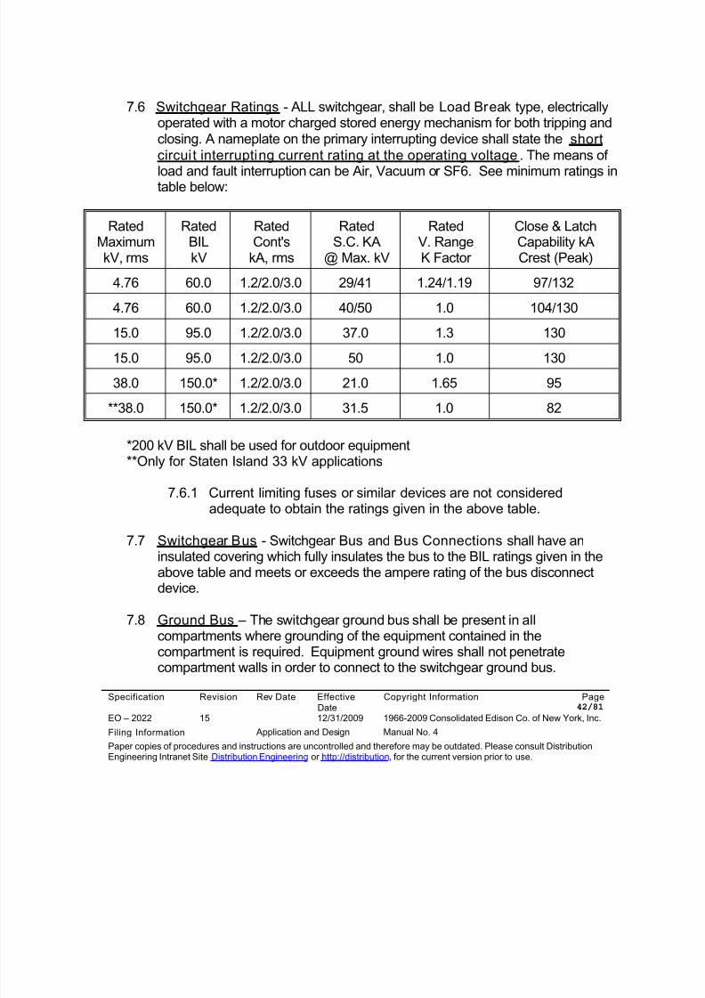
8/10/2019 Con Ed High Tension_EO-2022 (1)
http://slidepdf.com/reader/full/con-ed-high-tensioneo-2022-1 42/81
Specification Revision Rev Date EffectiveDate
Copyright Information Page 42/81
EO – 2022 15 12/31/2009 1966-2009 Consolidated Edison Co. of New York, Inc.
Filing Information Application and Design Manual No. 4
Paper copies of procedures and instructions are uncontrolled and therefore may be outdated. Please consult DistributionEngineering Intranet Site Distribution Engineering or http://distribution, for the current version prior to use.
7.6 Switchgear Ratings - ALL switchgear, shall be Load Break type, electricallyoperated with a motor charged stored energy mechanism for both tripping andclosing. A nameplate on the primary interrupting device shall state the shortcircuit interrupting current rating at the operating voltage. The means of
load and fault interruption can be Air, Vacuum or SF6. See minimum ratings intable below:
RatedMaximumkV, rms
RatedBILkV
RatedCont's
kA, rms
RatedS.C. KA
@ Max. kV
RatedV. RangeK Factor
Close & LatchCapability kACrest (Peak)
4.76 60.0 1.2/2.0/3.0 29/41 1.24/1.19 97/132
4.76 60.0 1.2/2.0/3.0 40/50 1.0 104/130
15.0 95.0 1.2/2.0/3.0 37.0 1.3 130
15.0 95.0 1.2/2.0/3.0 50 1.0 130
38.0 150.0* 1.2/2.0/3.0 21.0 1.65 95
**38.0 150.0* 1.2/2.0/3.0 31.5 1.0 82
*200 kV BIL shall be used for outdoor equipment**Only for Staten Island 33 kV applications
7.6.1 Current limiting fuses or similar devices are not consideredadequate to obtain the ratings given in the above table.
7.7 Switchgear Bus - Switchgear Bus and Bus Connections shall have aninsulated covering which fully insulates the bus to the BIL ratings given in theabove table and meets or exceeds the ampere rating of the bus disconnectdevice.
7.8 Ground Bus – The switchgear ground bus shall be present in allcompartments where grounding of the equipment contained in thecompartment is required. Equipment ground wires shall not penetratecompartment walls in order to connect to the switchgear ground bus.
8/10/2019 Con Ed High Tension_EO-2022 (1)
http://slidepdf.com/reader/full/con-ed-high-tensioneo-2022-1 43/81
Specification Revision Rev Date EffectiveDate
Copyright Information Page 43/81
EO – 2022 15 12/31/2009 1966-2009 Consolidated Edison Co. of New York, Inc.
Filing Information Application and Design Manual No. 4
Paper copies of procedures and instructions are uncontrolled and therefore may be outdated. Please consult DistributionEngineering Intranet Site Distribution Engineering or http://distribution, for the current version prior to use.
7.9 Grounding Devices – Grounding devices shall meet all the operating voltageand current requirements for switchgear as noted in paragraph 7.6 except forthe fault interrupting requirements.
7.10 Cubicle Doors - All medium voltage cubicles (front and rear) shall beaccessible through padlockable hinged doors. There shall be no exposed lowvoltage wiring in any medium voltage cubicles.
7.11 Barriers and Insulators - All penetrations (bus, wiring, etc.) between adjacentswitchgear cubicles shall be through Company approved barriers andinsulators.
7.12 Shutters - Drawout type circuit breaker switchgear cubicles shall beconstructed with shutters to cover the stationary contacts when the circuit
breaker is racked out of the cubicle. These shutters shall be mechanicallyinterlocked with the positioning of the breaker unit to ensure proper openingand alignment with the racking in and out of the circuit breaker. It isrecommended that the shutters be metallic and of suitable strength to protectagainst possible damage due to mechanical misalignment during circuitbreaker insertion.
7.13 Stop Blocks - Stop blocks shall inhibit any Ground and Test (G&T) devicefrom entering a Tie circuit breaker cubicle or any cubicle in which the G&Tdevice can inadvertently ground a paralleling bus .
7.14 Circuit Breaker Trip Interlocks - All circuit breaker and storage cubicles shallbe equipped with a trip free interlock. All circuit breakers and G&T devicesshall trip free if in the closed position upon insertion and removal from acubicle.
7.15 Fixed Type Circuit Breakers - Fixed type circuit breakers shall have aload break disconnect switch installed on its line and load side. A groundswitch shall be installed Company side of the line side disconnect switch.The Company shall approve the Customer’s interlock arrangement betweenthe disconnect switch, ground switch and the fixed type circuit breaker.
8/10/2019 Con Ed High Tension_EO-2022 (1)
http://slidepdf.com/reader/full/con-ed-high-tensioneo-2022-1 44/81
Specification Revision Rev Date EffectiveDate
Copyright Information Page 44/81
EO – 2022 15 12/31/2009 1966-2009 Consolidated Edison Co. of New York, Inc.
Filing Information Application and Design Manual No. 4
Paper copies of procedures and instructions are uncontrolled and therefore may be outdated. Please consult DistributionEngineering Intranet Site Distribution Engineering or http://distribution, for the current version prior to use.
7.16 Fused Loadbreak Disconnect Switches - Fused loadbreak disconnectswitches which are used as primary disconnect devices shall be electricallyoperable from a remote panel and shall NOT have their control switchesmounted on the compartment doors of the devices they are operating. The
control switches shall be mounted on a separate control panel with a mimicbus, which shows equipment layout for the remote operation and statusindication of the disconnect switches. The control panel can be installed atone end of the switchgear lineup, or at a remote location inside the switchgearroom. Fused loadbreak disconnect switches will be permitted on all 4 kVprimary systems and on certain 13 kV primary systems in Staten Island andWestchester. A 125VDC power supply, with a charger, shall be used for allrelay and control functions.
7.17 Locking - G&T devices shall be able to be locked in any operating position(open, closed, ground and disconnect position). Fixed type circuit breakers
shall be equipped with a key interlock to lock the circuit breaker in the openposition. Draw out type circuit breakers shall be equipped with a key interlockto lock the circuit breaker in the disconnect position. Loadbreak disconnectswitches shall be equipped with a key interlock to lock the disconnect switch inthe open position. Additional locks may be required by the Company forspecific applications.
7.18 Low Voltage Power Supply - The Customer shall install a suitably sized lowvoltage power supply for heaters, transformer cooling fans, receptacles,internal and external lighting, etc. Any instrument transformer installed beforethe first point of disconnection must have Company approval and be
connected phase to phase. The instrument transformer shall be able towithstand the Company cable proof testing values given in CompanySpecification EO-4019.
7.19 Circuit Breaker Trip Coils - All circuit breaker trip coil circuits shall beinterlocked with a normally open auxiliary breaker contact, to open the trip coilcircuit when the tripping coil has operated. All circuit breaker trip coils shall beseparately monitored with Company approved monitoring devices.
7.20 Circuit Breaker Control Switches - The primary service feeder and tie circuitbreakers shall NOT have their control switches mounted on the compartment
8/10/2019 Con Ed High Tension_EO-2022 (1)
http://slidepdf.com/reader/full/con-ed-high-tensioneo-2022-1 45/81
Specification Revision Rev Date EffectiveDate
Copyright Information Page 45/81
EO – 2022 15 12/31/2009 1966-2009 Consolidated Edison Co. of New York, Inc.
Filing Information Application and Design Manual No. 4
Paper copies of procedures and instructions are uncontrolled and therefore may be outdated. Please consult DistributionEngineering Intranet Site Distribution Engineering or http://distribution, for the current version prior to use.
doors of the devices they are operating. The control switches shall bemounted on a separate control panel with a mimic bus, which showsequipment layout for the remote operation and status indication of the circuitbreakers or disconnect switches. The control panel can be installed at one
end of the switchgear lineup, or at a remote location inside the switchgearroom The control panel shall have direct unobstructed access to an exit. Theexit path shall not pass by the controlled switchgear.
7.21 Maneuvering Switchgear - The Customer shall provide a convenient meansfor maneuvering all drawout type switchgear, and G&T devices (e.g., Dolly, 5thWheel, etc.).
8.0 MECHANICAL, ELECTRICAL, KEY INTERLOCKS AND AUTOMATICTRANSFER
8.1 Key Codes - Key Interlocks shall be installed to avoid inadvertent andunauthorized switchgear operation movements. Where key interlocks areemployed, each primary service feeder device shall be furnished with anindividual key code that is not operable with any other key interlock within theCustomer's system. Key codes for other devices shall be furnished as notedin other paragraphs in Section 8.0. A key interlock system shall inhibit allelectrical operations except for those operations that are performed in the testmode.
8.2 Fixed Type Circuit Breakers - Fixed type circuit breakers shall bedesigned with a line and load side disconnect switch. A fixed type circuit
breaker and line and load side disconnect switch combination shall befurnished with key interlocks such that opening and closing of thedisconnect switches is inhibited when the breaker is closed. The key codeshall be restricted to the breaker and disconnect switch combination.
8.3 Fused Disconnect Switch Cubicle Entry - Key interlocks shall inhibit thechanging a power fuse in a fused disconnect switch cubicle unless all powersources to the fuses are locked open. Barriers and warning signs shall beinstalled to prevent accidental contact with any energized cubicle componentswhen the fuses must be replaced.
8/10/2019 Con Ed High Tension_EO-2022 (1)
http://slidepdf.com/reader/full/con-ed-high-tensioneo-2022-1 46/81
Specification Revision Rev Date EffectiveDate
Copyright Information Page 46/81
EO – 2022 15 12/31/2009 1966-2009 Consolidated Edison Co. of New York, Inc.
Filing Information Application and Design Manual No. 4
Paper copies of procedures and instructions are uncontrolled and therefore may be outdated. Please consult DistributionEngineering Intranet Site Distribution Engineering or http://distribution, for the current version prior to use.
8.4 Ground Switch Interlocks - Ground switch and drawout circuit breaker orground switch and primary service feeder disconnect switch combinations shallbe key interlocked such that the ground switch is operable only when the linedisconnecting device is locked open and there is no voltage on the primary
service feeder. The interior of the ground switch compartment shall onlybe accessible when the ground switch is in the closed (ground) position.
8.5 Key Tagging and Key Storage Box - Every interlock key shall be tagged witha brass key tag. All spare interlocking keys for primary, secondary switchgearand G&T devices shall be delivered to the Company. All keys designated as
Company keys shall be turned over in TOTAL. The Customer shall furnishand install, in a convenient location, a Key Storage Box that will be padlockedby the Company.
8.6 Multi-Feeder Radial Installation Interlocks - At multi-feeder RADIAL type
installations, the Customer's primary service and secondary feeders shall beinterlocked to ensure that no Customer device can be closed to parallelfeeders at any point in the Customer's internal distribution system. Bus Tiecircuit breaker(s) shall be purchased with a by-pass key, allowing theCompany to parallel feeders during scheduled work or when the system isreturned to normal. The by-pass key is used only by the Company personneland is locked in the Key Storage Box.
8.7 Key Interlocking Sequence - The Company shall approve the Customer’sbreak before make mechanical key interlocking sequence. Customeroperating personnel shall be trained in the operation of the key interlocking
sequence and shall follow a Company approved Customer OperatingSpecification. Laminated key sequence operating instructions shall beprominently displayed at the project site.
8.8 Electrical Interlocks - In addition to the other interlocking requirementsdetailed in Section 8.0, the electrical interlocking system shall be designed asfollows:
8.8.1 The primary service circuit breaker shall be electrically interlocked withthe transformer main circuit breaker so that the transformer main circuit
8/10/2019 Con Ed High Tension_EO-2022 (1)
http://slidepdf.com/reader/full/con-ed-high-tensioneo-2022-1 47/81
Specification Revision Rev Date EffectiveDate
Copyright Information Page 47/81
EO – 2022 15 12/31/2009 1966-2009 Consolidated Edison Co. of New York, Inc.
Filing Information Application and Design Manual No. 4
Paper copies of procedures and instructions are uncontrolled and therefore may be outdated. Please consult DistributionEngineering Intranet Site Distribution Engineering or http://distribution, for the current version prior to use.
breaker cannot be closed unless the primary service circuit breaker isclosed.
8.8.2 The transformer main circuit breaker shall trip whenever the primary
service circuit breaker is opened.
8.9 Remote Electrical Control Systems - Remote Electrical Control Systemswhich permit the opening and closing of circuit breakers from a dispatchcontrol room shall have a system designed to meet all applicable conditionsstated in Sections 8.0 and 10.0 in addition to the following:
8.9.1 The Customer who applies for remote control system must havequalified operating personnel on duty, 7 days a week on a 24 hour aday basis.
8.9.2 The Customer's qualified operating personnel must secure permissionfrom the Company's District Operator before any operations areperformed.
8.9.3 The Customer must get the District Operator's permission prior toshifting the load, from one primary service feeder to another.
8.9.4 Updated relay and control schematics for the remote control systemmust be submitted to the Company for approval and record.
8.9.5 The maximum response of one hour is required by the Customer during
Company contingency conditions. Failure to meet the one hourresponse time shall only be excusable when it is beyond the Customerscontrol; i.e., severe weather, riots, floods, fires, etc.
8.9.6 For scheduled work on Company feeders the Customer will be given 12hour advance notice. The Customer shall rack-out his breakers andhave the feeder position accessible for grounding (if necessary).
8.9.7 If the maximum response time is not adhered to, the right to use remoteelectrical control will be withdrawn and mechanical interlocks will berequired.
8/10/2019 Con Ed High Tension_EO-2022 (1)
http://slidepdf.com/reader/full/con-ed-high-tensioneo-2022-1 48/81
Specification Revision Rev Date EffectiveDate
Copyright Information Page 48/81
EO – 2022 15 12/31/2009 1966-2009 Consolidated Edison Co. of New York, Inc.
Filing Information Application and Design Manual No. 4
Paper copies of procedures and instructions are uncontrolled and therefore may be outdated. Please consult DistributionEngineering Intranet Site Distribution Engineering or http://distribution, for the current version prior to use.
8.10 Automatic Transfer - Automatic Transfer of Radial feeders will be permittedfor Critical Customers. There shall be no paralleling of circuit breakers duringthe transfer operation; all automatic operations are break-before-make. The
Customer shall test and maintain the automatic transfer equipment asdetailed in Company Specification EO-4035 with the following exceptions; therelays shall be tested and the certified test reports submitted to the Companyevery 48 months. Failure to submit test reports may result in withdrawal ofpermission to use the automatic transfer system and key interlocks will berequired.
8.11 Automatic Transfer Function Guide - The Automatic Load Transfer systemshall function as follows:
8.11.1 Normal Status:
a. Both primary service feeder circuit breakers are closed andcarrying load.
b. The bus tie breaker is open.
8.11.2 When one of the Customer’s primary service feeder circuit breakertrips, the Customer’s bus tie breaker will close after a time delay ofone to ten seconds. To accomplish the autotransfer, the controlcircuitry must check the following:
a. There is no voltage present on the load side of the now openedprimary service feeder circuit breaker.
b. No fault current has passed through the now opened Customerline circuit breaker.
c. The Customer‘s primary service feeder circuit breaker did not failto open to clear the fault on the Customer’s premises.
8/10/2019 Con Ed High Tension_EO-2022 (1)
http://slidepdf.com/reader/full/con-ed-high-tensioneo-2022-1 49/81
Specification Revision Rev Date EffectiveDate
Copyright Information Page 49/81
EO – 2022 15 12/31/2009 1966-2009 Consolidated Edison Co. of New York, Inc.
Filing Information Application and Design Manual No. 4
Paper copies of procedures and instructions are uncontrolled and therefore may be outdated. Please consult DistributionEngineering Intranet Site Distribution Engineering or http://distribution, for the current version prior to use.
d. There is normal voltage present on the load side of thecompanion primary service feeder circuit breaker that will pick-upthe load.
8.11.3 When there is a fault condition on the load side of the primary servicefeeder circuit breaker, the primary service feeder circuit breaker willtrip, and the automatic transfer control circuitry shall inhibit transferand the shall check the following:
a. The primary service feeder circuit breaker has opened.
b. The Bus Tie circuit breaker has been blocked from closing.
8.11.4 Return to Normal Operation (Company controlled manual by-pass keyoperation)
a. Normal three phase voltage must be present on the line side of theopen primary service circuit breaker.
b. Phase sequence checks shall be made across the open primaryservice circuit breaker.
c. The primary service circuit breaker is closed.
d. The bus tie circuit breaker is opened to restore the system tonormal.
8.12 Automatic Transfer - Interlocks and Relays - Automatic Transfer electricalinterlocking and protective relaying systems shall be designed to accomplishthe following:
8.12.1 The bus tie circuit breaker cannot be closed after both primaryservice feeder circuit breakers are closed (can be defeated with amanual by-pass key).
8.12.2 The bus tie breaker cannot be closed if a fault condition exists on theload side of the either line circuit breaker or on the tie bus.
8/10/2019 Con Ed High Tension_EO-2022 (1)
http://slidepdf.com/reader/full/con-ed-high-tensioneo-2022-1 50/81
Specification Revision Rev Date EffectiveDate
Copyright Information Page 50/81
EO – 2022 15 12/31/2009 1966-2009 Consolidated Edison Co. of New York, Inc.
Filing Information Application and Design Manual No. 4
Paper copies of procedures and instructions are uncontrolled and therefore may be outdated. Please consult DistributionEngineering Intranet Site Distribution Engineering or http://distribution, for the current version prior to use.
8.12.3 A time delay shall inhibit transfer during voltage dips.
8.12.4 Retransfer of load is reestablished manually under Company
jurisdiction.
8.12.5 Facilities shall exist to allow the paralleling of the feeders to preventCustomer outages during system restoration and scheduled outages.During the paralleling operation, performed by Company employees,both primary service feeder and tie circuit breakers shall activate atimer to trip the tie breaker. The timer shall be adjustable 0-60seconds; settings will be given at the time of installation.
8.12.6 An alarm system shall be installed to alert the Customer’s operatorthat a transfer has occurred or the selector switch has been left in the
bypass position. When the alarm is activated, the Customer must callthe Company's District Operator for instructions.
8.13 Programmable Logic Controller (PLC) - The Customer will be permitted touse a PLC for system controls and alarm. Back-up signals shall be providedvia a hard-wire system for the tripping of the circuit breaker trip coils.
9.0 GROUNDING DEVICES - The Customer shall provide the means for grounding theprimary service feeder. Acceptable means for grounding the primary service feederdevices are G&T Devices and motor operated ground switches.
9.1 GROUND & TEST (G&T) DEVICE
9.1.1 Function and Storage - A Customer choosing to furnish a G&Tdevice for grounding of the primary service feeder shall maintain theG&T device at the facility. A minimum of one G&T device shall beprovided for installations with up to four primary service feeders. TheCompany may require additional G&T devices for installations withfive or more feeders. The G&T device shall be available for allprimary service feeders. If the G&T device cannot be moved to allprimary service feeders then additional G&T devices shall beprovided. The G&T device, used for primary service feeder grounding
8/10/2019 Con Ed High Tension_EO-2022 (1)
http://slidepdf.com/reader/full/con-ed-high-tensioneo-2022-1 51/81
Specification Revision Rev Date EffectiveDate
Copyright Information Page 51/81
EO – 2022 15 12/31/2009 1966-2009 Consolidated Edison Co. of New York, Inc.
Filing Information Application and Design Manual No. 4
Paper copies of procedures and instructions are uncontrolled and therefore may be outdated. Please consult DistributionEngineering Intranet Site Distribution Engineering or http://distribution, for the current version prior to use.
and testing shall be manufactured to occupy the same cubiclenormally occupied by the primary service feeder circuit breaker. TheG&T device shall be locked in a Company approved storage cubiclewhen not in use. The G&T device shall be rated to meet all voltage
and current requirements as the primary service breaker except forthe fault interrupting rating.
9.1.2 Key Interlocking - The G&T device shall be equipped with a keyinterlock system to allow for grounding and testing of theCompany’s primary service feeders. The keys that Companypersonnel will use to initiate the G&T grounding and testingoperations are kept under Company jurisdiction in the Company’sKey Storage Box.
9.1.3 Trip and Close Controls - Facilities shall be provided to operate (trip
and close) the G&T device from a remote position by an extensioncord (approximately twenty five feet long) with push-button controls.
9.1.4 Dual Function G&T Devices - The Company will permit theCustomer to use either separate G&T devices for Company andCustomer use or a dual function G&T device for Company andCustomer use. The key and mechanical interlocking system for thedual function G&T devices is much more complex and the followingadditional requirements are imposed:
• An additional key is required on the manual operator which selects
between the Customer and Company modes of operation.
• Additional keys shall be obtained from the associated mainsecondary circuit breaker and tie circuit breaker (if any).
The G&T device shall be interlocked so that only the Company’sprimary service feeder or Customer’s installation can be grounded atany one time. Transfer from the Company’s position to Customer’sposition shall be accomplished with a key interlock and shall beinhibited when the G&T device is in the cubicle. The G&T device,when not in use, shall be stored in set to the Customer mode of
8/10/2019 Con Ed High Tension_EO-2022 (1)
http://slidepdf.com/reader/full/con-ed-high-tensioneo-2022-1 52/81
Specification Revision Rev Date EffectiveDate
Copyright Information Page 52/81
EO – 2022 15 12/31/2009 1966-2009 Consolidated Edison Co. of New York, Inc.
Filing Information Application and Design Manual No. 4
Paper copies of procedures and instructions are uncontrolled and therefore may be outdated. Please consult DistributionEngineering Intranet Site Distribution Engineering or http://distribution, for the current version prior to use.
operation in a storage cubicle that is padlocked with a Company lock.The manual operator shall be plainly marked as CUSTOMER and
CON EDISON.
9.1.5 Test Receptacles - To test the Company’s primary service feeder,three, fully rated voltage test receptacles shall be provided on thefront of the G&T device which provide individual connections to eachphase of the LINE side of the G&T device. Testing of Customer'sLOAD side equipment shall also be accomplished via fully rated,voltage test receptacles, which are key interlocked to ensure a safeoperation.
9.1.6 Receptacle Shutters - All test receptacles shall be furnished withshutters to isolate the receptacles while not in use. The shutters shallbe key interlocked with the manual operator in such a manner that
they cannot be opened unless the G&T device is in the mode ofoperation assigned and the G&T device is closed (ground is applied).The key interlock shall allow the G&T device to be tripped open onlyafter the test receptacle shutters are closed or after the test probesare inserted and locked into the receptacles. The test receptaclesshall be interlocked with the operation of the G&T device to ensure
that the probes can only be removed when the G&T device is in theground position.
9.1.7 Test Probes and Cables - One set of test probes and with 25 lengthfoot cables shall be furnished with each G&T device. The probes and
cables shall be stored at the site. The cables shall have the sameinsulation voltage rating as the associated switchgear. The testcables shall be furnished with a lug for attachment to a test set.
9.1.8 G&T device - Interlocking Requirements - The switchgearmanufacturer shall provide a G&T device which will meet theCompany’s interlocking requirements. To initiate grounding andtesting of a Company feeder, Company personnel will obtain a KU
Key from the key storage box on the premises. The KU Key will beused to begin a series of interlocking moves that ensure that the G&Tdevice will be operated in a safe manner. The following describes the
8/10/2019 Con Ed High Tension_EO-2022 (1)
http://slidepdf.com/reader/full/con-ed-high-tensioneo-2022-1 53/81
Specification Revision Rev Date EffectiveDate
Copyright Information Page 53/81
EO – 2022 15 12/31/2009 1966-2009 Consolidated Edison Co. of New York, Inc.
Filing Information Application and Design Manual No. 4
Paper copies of procedures and instructions are uncontrolled and therefore may be outdated. Please consult DistributionEngineering Intranet Site Distribution Engineering or http://distribution, for the current version prior to use.
G&T interlocks and the sequence of moves that will ground thefeeder:
9.1.8.1 Key Lock #1 (Keys KU & KB) - The KU Key is inserted in
the G&T device Key Lock #1. The KU/KB Keys are rotatedto electrically enable/disable the G&T Device. The KU Keyis held captive and the KB Key is released when the G&Tdevice is electrically disabled. The KB Key is held captiveand the KU Key is released when the G&T device iselectrically enabled.
9.1.8.2 Key Lock #2 (Keys KB & KC) – The KB Key is inserted inKey Lock #2. The KB/KC Keys are rotated to mechanicallylock the G&T Device in the open position. The KB Key isheld captive and the KC Key is released when the G&T
device is mechanically locked. The KC Key is held captiveand the KB Key is released when the G&T device ismechanically unlocked.
9.1.8.3 Key Lock #3 (Key KC) - The KC Key is used to unlock the“lifting lever” that prevents the G&T device from beinginserted in the cubicle or that locks the G&T device in thecubicle. The KC Key is held captive in when the “liftinglever” is unlocked.
9.1.8.4 Key Lock #4 (Keys KB & KD) - The KB Key is inserted in
Key Lock #4 to mechanically lock the G&T Device in theclosed position; the KB Key is held captive and the KD Keyis released when the G&T device is mechanically locked inthe closed position.
9.1.8.5 Key lock #5 (Key KD) - The KD Key is used to open andlock the Test Port Shutters. The KD Key is held captivewhen the Test Port Shutters are unlocked. The KD Key isreleased when the Test Port Shutters are locked in thecovered position or when the Test Port Shutters havelocked the Test Probes in the Test Ports.
8/10/2019 Con Ed High Tension_EO-2022 (1)
http://slidepdf.com/reader/full/con-ed-high-tensioneo-2022-1 54/81
Specification Revision Rev Date EffectiveDate
Copyright Information Page 54/81
EO – 2022 15 12/31/2009 1966-2009 Consolidated Edison Co. of New York, Inc.
Filing Information Application and Design Manual No. 4
Paper copies of procedures and instructions are uncontrolled and therefore may be outdated. Please consult DistributionEngineering Intranet Site Distribution Engineering or http://distribution, for the current version prior to use.
9.1.8.6 Selector Switch - A three-position pistol grip switch -Trip/Off/Close. The Selector Switch shall be pad lockablein the Off position.
9.1.8.7 Padlockable Cover - Covers the manual Trip Push-button
9.1.8.8 Push-button Station – Open and Close buttons located atthe end of a 25 foot extension cord that is used to Trip andClose the G&T device.
9.2 GROUND SWITCHES
9.2.1 Function – Customers who utilize fused loadbreak disconnectswitches as primary disconnect devices shall provide a line side
ground switch for each primary service feeder. Ground switches maybe provided in lieu of a G&T device for installations equipped withcircuit breakers as the primary disconnect devices. Ground switchesshall be installed in separate compartments when used with circuitbreakers. Ground switches shall be electrically operable from a
remote panel and shall NOT have their control switches mounted onthe compartment doors of the devices they are operating. The controlswitches shall be mounted on a separate control panel with a mimicbus, which shows equipment layout for the remote operation andstatus indication of the ground switches. The control panel can beinstalled at one end of the switchgear lineup, or at a remote location
inside the switchgear room.
9.2.2 Key Interlocking - The ground switches shall be equipped with a keyinterlock system to allow for grounding of the Company’s primaryservice feeders. The keys that Company personnel will use to initiatethe G&T grounding and testing operations are kept under Company
jurisdiction in the Company’s Key Storage Box.
9.2.3 Ground Switch Interlocking Requirements - The followingdescribes the required key, mechanical and electric interlocks of
8/10/2019 Con Ed High Tension_EO-2022 (1)
http://slidepdf.com/reader/full/con-ed-high-tensioneo-2022-1 55/81
Specification Revision Rev Date EffectiveDate
Copyright Information Page 55/81
EO – 2022 15 12/31/2009 1966-2009 Consolidated Edison Co. of New York, Inc.
Filing Information Application and Design Manual No. 4
Paper copies of procedures and instructions are uncontrolled and therefore may be outdated. Please consult DistributionEngineering Intranet Site Distribution Engineering or http://distribution, for the current version prior to use.
the electrically operated disconnect switch and the associatedground switch.
9.2.4 Device Descriptions
9.2.4.1 Utility Lockbox (Key KU) – Padlockable box located on thepremises for Utility use. This lockbox houses the KU Key.
9.2.4.2 Selector Switch - A three-position pistol grip switch locatedon the Ground Switch cubicle - Open/Off/Close.
9.2.4.3 Remote Control Panel – Operator’s panel with mimic buslocated away from the front of the switchgear compartmentto permit operation of the Line and Ground Switches.Indicating lights are provided to show the open and closestatus for each remotely operated device.
9.2.4.4 Remote Control Switch - A three-position pistol grip switchlocated on the Remote Control Panel - Open/Close, returnto center [after open (green flag) and after close (red flag)].
9.2.4.5 Padlockable Cover – Manual Trip and Close Push-buttons located on the Ground Switch cubicle are equippedwith a padlockable cover for Utility use.
9.2.4.6 Key Lock #1 (Key KB) – Key operated switch located onthe Utility Disconnect Switch cubicle that mechanically locks
the Utility Disconnect Switch in the open position andelectrically disables the motor operated Disconnect Switch.Key KB is held captive when the Disconnect Switch isclosed. Key KB is released when the Disconnect Switch isopened. The disconnect switch can be operated only whenKB is in Key Lock #1 and rotated to the captive position.
9.2.4.7 Key Lock #2 (Keys KU, KB & KC) – Key operated switchand interlock located on the Utility Ground Switch cubiclethat electrically disables the motor operated Utility Ground
8/10/2019 Con Ed High Tension_EO-2022 (1)
http://slidepdf.com/reader/full/con-ed-high-tensioneo-2022-1 56/81
Specification Revision Rev Date EffectiveDate
Copyright Information Page 56/81
EO – 2022 15 12/31/2009 1966-2009 Consolidated Edison Co. of New York, Inc.
Filing Information Application and Design Manual No. 4
Paper copies of procedures and instructions are uncontrolled and therefore may be outdated. Please consult DistributionEngineering Intranet Site Distribution Engineering or http://distribution, for the current version prior to use.
Switch and locks the Selector Switch in the Off position.Key KC is held captive. Key KC will be designated KeyKC1 when Key Lock #5 is present. Inserting Key KU andKey KB in Key Lock #2 lets the operator rotate all three
keys and release Key KC. When Key KC is released KeyKU and Key KB are held captive, the motor operator iselectrically enabled and the Selector Switch can be movedto the Open or Close positions.
9.2.4.8 Key Lock #3 (Keys KC & KD) - Key operated interlocklocated on the Utility Ground Switch cubicle thatmechanically locks the Utility Ground Switch in the open orclosed positions and prevents inadvertent operation in theevent of a failure in the Ground Switch electrical system. Ifthe mechanical design of the Ground Switch precludes the
possibility of using a single lock to mechanically lock theGround Switch in both the open and closed positions thenKey Lock #2 will mechanically lock the Ground Switch in theopen position and Key KC will be designated Key KC1. KeyKD is held captive. Inserting Key KC in Key Lock #3 letsthe operator rotate both keys and release Key KD. WhenKey KD is released Key KC is held captive and the GroundSwitch is mechanically unlocked.
9.2.4.9 Key Lock #4 (Key KD) – Key operated switch located onthe remote control panel that electrically enables the Utility
Ground Switch Remote Control Switch located on theremote control panel when Key KD is inserted and rotatedin Key Lock #4.
9.2.4.10 Key Lock #5 (Keys KC2 & KD) - Key operated interlocklocated on the Utility Ground Switch cubicle thatmechanically locks the Utility Ground Switch in the closedposition and prevents inadvertent operation in the event ofa failure in the Ground Switch electrical system. This keywill be required only if mechanical design of the GroundSwitch prevents the use of Key Lock #2 to mechanically
8/10/2019 Con Ed High Tension_EO-2022 (1)
http://slidepdf.com/reader/full/con-ed-high-tensioneo-2022-1 57/81
Specification Revision Rev Date EffectiveDate
Copyright Information Page 57/81
EO – 2022 15 12/31/2009 1966-2009 Consolidated Edison Co. of New York, Inc.
Filing Information Application and Design Manual No. 4
Paper copies of procedures and instructions are uncontrolled and therefore may be outdated. Please consult DistributionEngineering Intranet Site Distribution Engineering or http://distribution, for the current version prior to use.
lock the Ground Switch in the closed position. Key KC2 isheld captive. Inserting Key KD in Key Lock #5 lets theoperator rotate both keys and release Key KC2. When KeyKC2 is released Key KD is held captive and the Ground
Switch is mechanically locked in the closed position.
9.2.5 Sequence 1 To Apply Ground On The Utility Feeder:
9.2.5.1 Key Lock #1 (Key KB) – When the Disconnect Switch is inthe closed position the KB Key is held captive in Key Lock#1. When the Disconnect Switch is opened; the KB keycan be rotated and removed from Key Lock #1 therebymechanically locking the Disconnect Switch in the openposition and electrically disabling the Disconnect Switch.
9.2.5.2 Key Lock #2 (Keys KU, KB & KC) - The KC Key is heldcaptive in Key Lock #2. The KU Key is removed from theUtility Lock Box and the KB key that was previouslyremoved from Key Lock #1 are inserted in the UtilityGround Switch Key Lock #2. The KU/KB/KC Keys arerotated to electrically enable the Ground Switch and unlockthe Selector Switch. The KU Key and KB keys are heldcaptive and the KC Key is released.
9.2.5.3 Selector Switch - The Selector Switch is rotated to theClose position.
9.2.5.4 Key Lock #3 (Keys KC & KD) - The KD Key is heldcaptive in Key Lock #3. The KC Key is inserted in KeyLock #3. The KC/KD Keys are rotated to mechanicallyunlock the Utility Ground Switch. The KC Key is heldcaptive and the KD Key is released.
9.2.5.5 Key Lock #4 (Key KD) – The KD Key is inserted in KeyLock #4 located on the Remote Control Panel and rotatedto electrically enable the Utility Ground Switch RemoteControl Switch. The operator verifies that the area in front
8/10/2019 Con Ed High Tension_EO-2022 (1)
http://slidepdf.com/reader/full/con-ed-high-tensioneo-2022-1 58/81
Specification Revision Rev Date EffectiveDate
Copyright Information Page 58/81
EO – 2022 15 12/31/2009 1966-2009 Consolidated Edison Co. of New York, Inc.
Filing Information Application and Design Manual No. 4
Paper copies of procedures and instructions are uncontrolled and therefore may be outdated. Please consult DistributionEngineering Intranet Site Distribution Engineering or http://distribution, for the current version prior to use.
of and in the vicinity of the Utility Ground Switch is clear ofpersonnel and operates the Ground Switch Remote ControlSwitch to close the Ground Switch.
9.2.5.6 Key Lock #3 (Keys KC & KD) - After the Utility GroundSwitch is closed, Key KD is removed from Key Lock #4 andinserted in Key Lock #3. The KC/KD Keys are rotated tomechanically lock the Ground Switch in the closed position.The KD Key is held captive and the KC Key is released.
9.2.5.7 Selector Switch - The Selector Switch is rotated to the“Off” position.
9.2.5.8 Key Lock #2 (Keys KU, KB & KC) – The KC Key isinserted in Key Lock #2. The KU/KB/KC Keys are rotated
to electrically disable the Ground Switch and lock theSelector Switch in the OFF position. The KC Key is heldcaptive and the KU & KB Keys are released. The KU & KBKeys may now be removed from Key Lock # 2 and lockedin the Utility Lockbox to prevent unauthorized operation ofeither the Utility Ground Switch or the Disconnect Switch.
9.2.6 Sequence 2 To Apply Ground On The Util ity Feeder :
9.2.6.1 Key Lock #1 (Key KB) – When the Disconnect Switch isclosed the KB Key is held captive in Key Lock #1. When
the Disconnect Switch is opened; the KB key can berotated and removed from Key Lock #1 therebymechanically locking the Disconnect Switch in the openposition electrically disabling the Disconnect Switch.
9.2.6.2 Key Lock #2 (Keys KU, KB & KC1) – The KC1 Key isheld captive in Key Lock #2. The KU Key is removed fromthe Utility Lockbox and the KB key that was previouslyremoved from Key Lock #1 are inserted in the GroundSwitch Key Lock #2. The KU/KB/KC1 Keys are rotated toelectrically enable the Ground Switch and unlock the
8/10/2019 Con Ed High Tension_EO-2022 (1)
http://slidepdf.com/reader/full/con-ed-high-tensioneo-2022-1 59/81
Specification Revision Rev Date EffectiveDate
Copyright Information Page 59/81
EO – 2022 15 12/31/2009 1966-2009 Consolidated Edison Co. of New York, Inc.
Filing Information Application and Design Manual No. 4
Paper copies of procedures and instructions are uncontrolled and therefore may be outdated. Please consult DistributionEngineering Intranet Site Distribution Engineering or http://distribution, for the current version prior to use.
Selector Switch. The KU Key and KB keys are held captiveand the KC1 Key is released.
9.2.6.3 Selector Switch - The Selector Switch is rotated to the
Close position.
9.2.6.4 Key Lock #3 (Keys KC1 & KD) – The KD Key is heldcaptive in Key Lock #3. The KC1 Key is inserted in KeyLock #3. The KC1/KD Keys are rotated to mechanicallyunlock the Ground Switch. The KC1 Key is held captiveand the KD Key is released.
9.2.6.5 Key Lock #4 (Key KD) – The KD Key is inserted in KeyLock #4 located on the Remote Control Panel and rotatedto electrically enable the Utility Ground Switch Remote
Control Switch. The operator verifies that the area in frontof and in the vicinity of the Utility Ground Switch is clear ofpersonnel and operates the Ground Switch Remote ControlSwitch to close the Ground Switch.
9.2.6.6 Key Lock #5 (Keys KC2 & KD) - After Ground Switch isclosed, Key KD is removed from Key Lock #4 and insertedin Key Lock #5. The KD/KC2 Keys are rotated tomechanically lock the Ground Switch in the closed position.The KD Key is held captive and the KC2 Key is released.
9.2.6.7 Selector Switch - The Selector Switch is rotated to the Offposition.
9.2.6.8 Key Lock #2 (Keys KU, KB & KC2) – The KC2 Key isinserted in Key Lock #2 in place of KC1. The KU/KB/KC2Keys are rotated to electrically disable the Ground Switchand lock the Selector Switch in the OFF position. The KC2Key is held captive and the KU & KB Keys are released.The KU & KB Keys may now be removed from Key Lock #2 and locked in the Utility Lockbox to prevent unauthorized
8/10/2019 Con Ed High Tension_EO-2022 (1)
http://slidepdf.com/reader/full/con-ed-high-tensioneo-2022-1 60/81
Specification Revision Rev Date EffectiveDate
Copyright Information Page 60/81
EO – 2022 15 12/31/2009 1966-2009 Consolidated Edison Co. of New York, Inc.
Filing Information Application and Design Manual No. 4
Paper copies of procedures and instructions are uncontrolled and therefore may be outdated. Please consult DistributionEngineering Intranet Site Distribution Engineering or http://distribution, for the current version prior to use.
operation of either the Utility Ground Switch or theDisconnect Switch.
9.2.7 Additional Requirements For Ground and Disconnect
Switches:
9.2.7.1 Electric interlocks shall be provided to prevent closing of aGround Switch when the associated Line Switch is closed.
9.2.7.2 Electric interlocks shall be provided to prevent closing ofthe Line Switch when an associated Ground Switch isclosed.
9.2.7.3 Mechanical or key interlocks shall be provided to permitaccess to the interior of the Line Switch compartment only
when the Line Switch is open.
9.2.7.4 Mechanical or key interlocks shall be provided to permitaccess to the interior of a Ground Switch compartment onlywhen the Ground Switch is closed.
9.2.7.5 Barrier panels shall be provided in the Line Switchcompartment to minimize the possibility of contact withenergized parts when the Line Switch compartment isopen.
9.2.7.6 KB, KC and KD keys and Line and Ground Switchcompartment access keys shall be uniquely keyed to eachdevice and fitted with identifying tags.
10.0 SWITCHGEAR PROTECTION AND CONTROL EQUIPMENT
10.1 Customer Requirements - The Customer shall furnish, install and maintainall protective relays, voltage transformers and current transformers (exceptthose furnished by the Company for revenue metering), trip/control circuitsrequired for the proper protection and operation of the service equipment andthe Company's primary service feeders. The required protection shall be in
8/10/2019 Con Ed High Tension_EO-2022 (1)
http://slidepdf.com/reader/full/con-ed-high-tensioneo-2022-1 61/81
Specification Revision Rev Date EffectiveDate
Copyright Information Page 61/81
EO – 2022 15 12/31/2009 1966-2009 Consolidated Edison Co. of New York, Inc.
Filing Information Application and Design Manual No. 4
Paper copies of procedures and instructions are uncontrolled and therefore may be outdated. Please consult DistributionEngineering Intranet Site Distribution Engineering or http://distribution, for the current version prior to use.
accordance with the latest IEEE, ANSI, NEMA standards and as generallyoutlined herein, in the General Specification and other Companyspecifications listed in the reference section (see Section 14.0).
10.2 Protective Relay Design – The following are the minimum protective relayrequirements for Customer substations. Additional protective relayequipment may be required for specific installations.
10.2.1General – All protective relays shall be utility grade in drawout cases.
10.2.1.2 Electromechanical relays shall be equipped with built-intest-plug facilities or equivalent external test switches fortesting and calibrating the relays.
10.2.1.3 Microprocessor-based relays shall have built-in self-test
functions that with an alarm contact that shall be connectedto the Customer’s substation monitoring system.
10.2.1.4 Auxil iary relays in protective relay circuits shall be utilitygrade with screw terminal connections (plug-in relays arenot acceptable).
10.2.1.5 All protective relays shall provide target indication when theassociated device is tripped.
10.2.2 Short Circuit & Coordination Study – The Customer must submit a
Short Circuit & Coordination Study for review and approval. Apreliminary study may be prepared in the early design stages so thatequipment ratings, instrument transformer ratios and relay types canbe specified. The Customer's protective relay system shall bedesigned to avoid simultaneous tripping of supply feeders forsecondary faults. Note: All protection devices shall be properlycalibrated and coordinated to ensure a minimum fault clearing time.
10.2.3 Trip Circuit Monitoring – Trip circuit monitoring is required for theprimary service feeder, main transformer and bus-tie circuit breakersand the associated lockout relays.
8/10/2019 Con Ed High Tension_EO-2022 (1)
http://slidepdf.com/reader/full/con-ed-high-tensioneo-2022-1 62/81
Specification Revision Rev Date EffectiveDate
Copyright Information Page 62/81
EO – 2022 15 12/31/2009 1966-2009 Consolidated Edison Co. of New York, Inc.
Filing Information Application and Design Manual No. 4
Paper copies of procedures and instructions are uncontrolled and therefore may be outdated. Please consult DistributionEngineering Intranet Site Distribution Engineering or http://distribution, for the current version prior to use.
10.2.3.1 Trip circuit monitoring shall be equipped with an alarmcontact that is connected to the Customer’s substationmonitoring system.
10.2.3.2 Trip circuit monitoring shall be connected at the end of thetrip ladder so that the circuit breaker or lockout relay trip coiland the associated trip circuit wiring is monitored.
10.2.3.3 Trip circuit monitoring that is connected to a category alarmshall be designed to prevent masking of the category alarmwhen the associated circuit breaker is open or in the test ordisconnect position or when the associated lockout relay is inthe operate position.
10.2.4 VT Secondary - The VT secondaries shall be non-fused forprotective relay connection.
10.2.5 Alarm Monitoring - All alarm signals shall be transmitted to theCustomer’s operating facility that is actively monitored on a 24-hourbasis.
10.2.6 Zero Sequence Voltage Protection – Zero sequence voltageprotection is required for all Customers supplied at 33 kV, 27 kV and13 kV. Refer to paragraph 10.2.9.3 for additional details.
10.2.7 Switch Fuse Installations – The primary service feeder fuseshall be equipped with open phase protection. Overcurrentprotection shall prevent the operation of the associated load-break switch when the current through the switch exceeds itsrated interrupt capability.
10.2.8 Radial Installations - Circuit Breaker – The primary servicefeeder circuit breaker relay package includes three-phase andground overcurrent relays. Relays shall trip the associated circuitbreaker via a manually reset lockout relay. Overcurrent relaysassociated with transformer primaries shall be equipped with
8/10/2019 Con Ed High Tension_EO-2022 (1)
http://slidepdf.com/reader/full/con-ed-high-tensioneo-2022-1 63/81
Specification Revision Rev Date EffectiveDate
Copyright Information Page 63/81
EO – 2022 15 12/31/2009 1966-2009 Consolidated Edison Co. of New York, Inc.
Filing Information Application and Design Manual No. 4
Paper copies of procedures and instructions are uncontrolled and therefore may be outdated. Please consult DistributionEngineering Intranet Site Distribution Engineering or http://distribution, for the current version prior to use.
instantaneous elements. We recommend a differential relaypackage for the power transformers.
10.2.9 Multiple Feeder Substations – The protective relay system shall
be designed and coordinated so that no single fault will cause anoutage of the entire Customer substation or the loss of multipleCompany feeders. In addition to the requirements for radialinstallations, substations supplied by two or more feeders that areoperated in parallel by the Customer shall include the followingprotective relay functions:
10.2.9.1 Three-phase directional overcurrent relays (devicenumber 67) that trip the associated circuit breakerdirectly. The directional overcurrent relays shall trip forcurrent flowing towards the Con Edison system. The
directional overcurrent relays shall be set to clearbackfeed via the Customer’s substation into multiphase-faults on the Con Edison supply feeders.
10.2.9.2 Reverse power relay (device number 32) that trips theassociated circuit breaker directly. The reverse powerrelay shall trip for power flow towards the Con Edisonsystem. The reverse power relay shall be set to clearbackfeed via the Customer’s substation to loadsconnected to the Con Edison supply feeders.
10.2.9.3 Zero sequence voltage detection for ungroundedsystems (device numbers 27 & 59) that trip theassociated circuit breaker directly. These relays shall besupplied from:
o A phase-to-ground connected VT located on the loadside of the primary service feeder circuit breaker or
o A phase-to-ground connected coupling capacitorpotential device (CCPD) located on the line side of theCustomer’s primary service feeder circuit breaker.
8/10/2019 Con Ed High Tension_EO-2022 (1)
http://slidepdf.com/reader/full/con-ed-high-tensioneo-2022-1 64/81
Specification Revision Rev Date EffectiveDate
Copyright Information Page 64/81
EO – 2022 15 12/31/2009 1966-2009 Consolidated Edison Co. of New York, Inc.
Filing Information Application and Design Manual No. 4
Paper copies of procedures and instructions are uncontrolled and therefore may be outdated. Please consult DistributionEngineering Intranet Site Distribution Engineering or http://distribution, for the current version prior to use.
Note: all equipment connected to the line side of themain primary service feeder circuit breaker must be ableto withstand Con Edison periodic feeder hi-pot testing.Drawing No. 1 is a conceptual example of the scheme
connected to a load-side phase-to-ground VT.
10.2.9.4 Transformer main circuit breakers shall be equippedwith three phase overcurrent relays that trip theassociated circuit breaker via a manually reset lockoutrelay.
10.2.9.5 Transformer differential protection is recommendedfor all transformers with a base rating greater than 2500kVA. The Company for specific Customer installationsmay require the installation of transformer differential
protection. Transformer differential relays shall trip theassociated primary and secondary circuit breakers via adedicated lockout relay.
10.2.9.6 Transformer neutral overcurrent relays arerecommended. The Company for specific Customerinstallations may require the installation of transformerneutral overcurrent relays. Transformer neutralovercurrent relays shall trip via a lockout relay.
10.2.9.7 Bus tie circuit breakers require automatic tripping via
lockout relays.
10.2.9.8 Bus differential protection is recommended for thetransformer secondary buses. The Company forspecific Customer installations may require theinstallation of bus differential protection.
10.2.9.9 Overcurrent protection is recommended for the bus tiecircuit breakers and/or the transformer secondary buses.The Company for specific Customer installations may
require the installation of overcurrent protection.
8/10/2019 Con Ed High Tension_EO-2022 (1)
http://slidepdf.com/reader/full/con-ed-high-tensioneo-2022-1 65/81
Specification Revision Rev Date EffectiveDate
Copyright Information Page 65/81
EO – 2022 15 12/31/2009 1966-2009 Consolidated Edison Co. of New York, Inc.
Filing Information Application and Design Manual No. 4
Paper copies of procedures and instructions are uncontrolled and therefore may be outdated. Please consult DistributionEngineering Intranet Site Distribution Engineering or http://distribution, for the current version prior to use.
10.2.9.10 For installations whose design is based of synchronizingbuses, reactor buses, etc., the protection requirementsfor transformer buses and bus tie circuit breakers shall
apply.
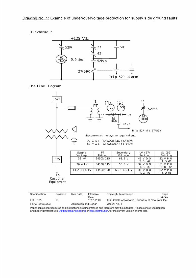
8/10/2019 Con Ed High Tension_EO-2022 (1)
http://slidepdf.com/reader/full/con-ed-high-tensioneo-2022-1 66/81
DC Schemat i c
Specification Revision Rev Date EffectiveDate
Copyright Information Page 66/81
EO – 2022 15 12/31/2009 1966-2009 Consolidated Edison Co. of New York, Inc.
Filing Information Application and Design Manual No. 4
Paper copies of procedures and instructions are uncontrolled and therefore may be outdated. Please consult DistributionEngineering Intranet Site Distribution Engineering or http://distribution, for the current version prior to use.
+125 Vdc
62 TDDO 0. 5 Sec.
52P/ 2762
52P/ a
59
27/ 59X
Tr i p 52P Al ar m
One Li ne Di agr am
Drawing No. 1: Example of under/overvoltage protection for supply s ide ground faults
52P
52P/ b
52S
1PT
27
62 TDDO
59
( 1)( 1)
52P/ a
62 TDDO
( +)
( +)( +)
Tr i p 52P vi a 27/ 59x
Recommended r el ays or equi val ent .
Suppl yVol t age
PTRati ng
SecondaryVol t age
UV (27)Set t i ng
OV (59)Sett i ng
33 kV 34500/ 115 63. 5 V 41 V D. O. T. D. #2
82 V P. U. T. D. #2
26. 4 kV 34500/ 115 50. 8 V 32 V D. O. T. D. #2
61 V P. U. T. D. #2
13. 2- 13. 8 kV 14400/ 120 63. 5- 66. 4 V 41 V D. O. T. D. #2
82 V P. U. T. D. #2
27 = G. E. 12I AV54E14A ( 32- 80V)59 = G. E. 12I AV51A1A ( 55- 140V)
ToCust omerEqui pment
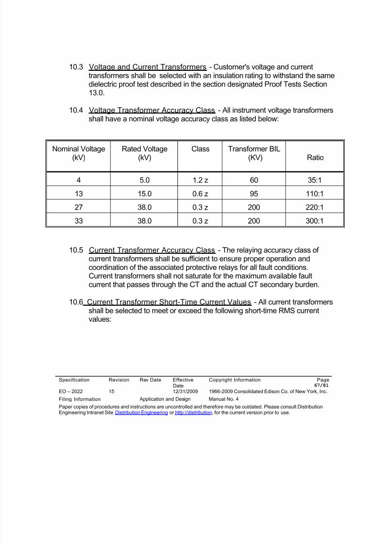
8/10/2019 Con Ed High Tension_EO-2022 (1)
http://slidepdf.com/reader/full/con-ed-high-tensioneo-2022-1 67/81
Specification Revision Rev Date EffectiveDate
Copyright Information Page 67/81
EO – 2022 15 12/31/2009 1966-2009 Consolidated Edison Co. of New York, Inc.
Filing Information Application and Design Manual No. 4
Paper copies of procedures and instructions are uncontrolled and therefore may be outdated. Please consult DistributionEngineering Intranet Site Distribution Engineering or http://distribution, for the current version prior to use.
10.3 Voltage and Current Transformers - Customer's voltage and currenttransformers shall be selected with an insulation rating to withstand the samedielectric proof test described in the section designated Proof Tests Section
13.0.
10.4 Voltage Transformer Accuracy Class - All instrument voltage transformersshall have a nominal voltage accuracy class as listed below:
Nominal Voltage(kV)
Rated Voltage(kV)
Class Transformer BIL(KV) Ratio
4 5.0 1.2 z 60 35:1
13 15.0 0.6 z 95 110:1
27 38.0 0.3 z 200 220:1
33 38.0 0.3 z 200 300:1
10.5 Current Transformer Accuracy Class - The relaying accuracy class ofcurrent transformers shall be sufficient to ensure proper operation andcoordination of the associated protective relays for all fault conditions.Current transformers shall not saturate for the maximum available fault
current that passes through the CT and the actual CT secondary burden.
10.6 Current Transformer Short-Time Current Values - All current transformersshall be selected to meet or exceed the following short-time RMS currentvalues:
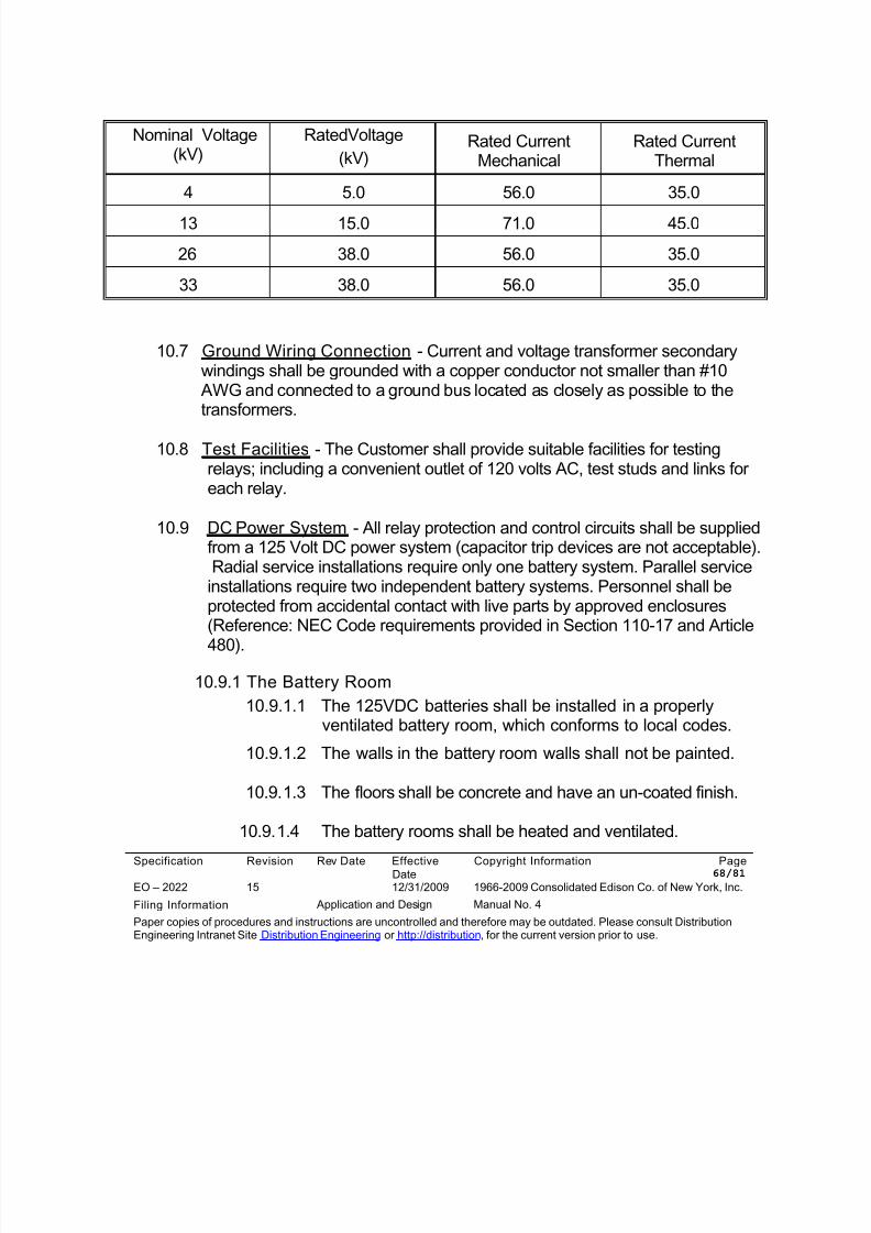
8/10/2019 Con Ed High Tension_EO-2022 (1)
http://slidepdf.com/reader/full/con-ed-high-tensioneo-2022-1 68/81
Specification Revision Rev Date EffectiveDate
Copyright Information Page 68/81
EO – 2022 15 12/31/2009 1966-2009 Consolidated Edison Co. of New York, Inc.
Filing Information Application and Design Manual No. 4
Paper copies of procedures and instructions are uncontrolled and therefore may be outdated. Please consult DistributionEngineering Intranet Site Distribution Engineering or http://distribution, for the current version prior to use.
Nominal Voltage(kV)
RatedVoltage
(kV)Rated Current
MechanicalRated Current
Thermal
4 5.0 56.0 35.0
13 15.0 71.0 45.0
26 38.0 56.0 35.0
33 38.0 56.0 35.0
10.7 Ground Wiring Connection - Current and voltage transformer secondarywindings shall be grounded with a copper conductor not smaller than #10
AWG and connected to a ground bus located as closely as possible to thetransformers.
10.8 Test Facilities - The Customer shall provide suitable facilities for testingrelays; including a convenient outlet of 120 volts AC, test studs and links foreach relay.
10.9 DC Power System - All relay protection and control circuits shall be suppliedfrom a 125 Volt DC power system (capacitor trip devices are not acceptable).Radial service installations require only one battery system. Parallel serviceinstallations require two independent battery systems. Personnel shall beprotected from accidental contact with live parts by approved enclosures(Reference: NEC Code requirements provided in Section 110-17 and Article
480).
10.9.1 The Battery Room
10.9.1.1 The 125VDC batteries shall be installed in a properlyventilated battery room, which conforms to local codes.
10.9.1.2 The walls in the battery room walls shall not be painted.
10.9.1.3 The floors shall be concrete and have an un-coated finish.
10.9.1.4 The battery rooms shall be heated and ventilated.
8/10/2019 Con Ed High Tension_EO-2022 (1)
http://slidepdf.com/reader/full/con-ed-high-tensioneo-2022-1 69/81
Specification Revision Rev Date EffectiveDate
Copyright Information Page 69/81
EO – 2022 15 12/31/2009 1966-2009 Consolidated Edison Co. of New York, Inc.
Filing Information Application and Design Manual No. 4
Paper copies of procedures and instructions are uncontrolled and therefore may be outdated. Please consult DistributionEngineering Intranet Site Distribution Engineering or http://distribution, for the current version prior to use.
10.9.1.5 The battery rooms shall be separated.
10.9.1.6 The light switches and receptacles in the battery room shall
be made of explosion proof materials.
10.9.1.7 The light fixtures shall not be located directly over the batteryracks.
10.9.1.8 Spill containment shall be provided on the floor under thebattery racks.
10.9.1.9 The batteries shall be mounted in a single row or a two-tierrack. Racks shall be epoxy-coated steel and shall be solidlygrounded to the station ground.
10.9.1.10 The exterior door of each battery room shall have a sign thatidentifies the room (example: 125VDC Battery Room No.1).
10.9.1.11 The rectifier, the DC panel and transfer switches shall belocated outside the battery room.
10.9.1.12 It is recommended that an eye wash station be installedoutside the battery rooms.
10.9.2 The Battery System
10.9.2.1 A Radial supply battery system shall consist of a rectifier,125VDC batteries, a battery disconnect switch and a DCpanel.
10.9.2.2 A Parallel supply battery system consists of two ACautomatic transfer switches, two rectifiers, two 125VDCbatteries, two DC non-fused three-pole battery disconnectswitches, two DC automatic transfer switches and two DCpanels.
8/10/2019 Con Ed High Tension_EO-2022 (1)
http://slidepdf.com/reader/full/con-ed-high-tensioneo-2022-1 70/81
Specification Revision Rev Date EffectiveDate
Copyright Information Page 70/81
EO – 2022 15 12/31/2009 1966-2009 Consolidated Edison Co. of New York, Inc.
Filing Information Application and Design Manual No. 4
Paper copies of procedures and instructions are uncontrolled and therefore may be outdated. Please consult DistributionEngineering Intranet Site Distribution Engineering or http://distribution, for the current version prior to use.
10.9.2.3 The three phase, 208VAC supply to the AC automatictransfer switches shall be supplied from separate ACsources.
10.9.2.4 The two independent DC systems shall not be tied togetherunder any situation. Transfer shall be set to occur wheneverthe normal supply drops below 90% of rated voltage.
10.9.2.5 A ground detection device shall be installed on each DCsystem.
10.9.2.6 The rectifiers shall be furnished with failure alarms to indicatelow voltage and ground. The failure alarms shall be sent tothe station alarm annunciator panel that shall be monitoredon a continuous basis. The rectifiers shall be equipped with
DC ammeters and voltmeters. It shall be noted that on rareoccasions the rectifiers may be required to supply the dcpanel without the batteries connected.
10.9.2.7 Each of the rectifiers shall have sufficient capacity to supplythe total station steady state DC load, plus the powerrequired to charge a discharged battery from 1.75 volts percell to 2.33 volts per cell at the maximum charge rate, plus aspare capacity of 15%.
10.9.2.8 The desirable continuous current output rating of the rectifier
shall not exceed 25% of the 8-hour ampere rating of thebattery.
10.9.2.9 The rectifiers shall have sufficient capacity to simultaneouslytrip the single fault maximum number of circuit breakers inthe substation with the ac and dc transfer switches in thenormal position.
10.9.2.10 Batteries shall be rated on the DC load profile with theirability to supply a constant DC current for eight hours.
8/10/2019 Con Ed High Tension_EO-2022 (1)
http://slidepdf.com/reader/full/con-ed-high-tensioneo-2022-1 71/81
Specification Revision Rev Date EffectiveDate
Copyright Information Page 71/81
EO – 2022 15 12/31/2009 1966-2009 Consolidated Edison Co. of New York, Inc.
Filing Information Application and Design Manual No. 4
Paper copies of procedures and instructions are uncontrolled and therefore may be outdated. Please consult DistributionEngineering Intranet Site Distribution Engineering or http://distribution, for the current version prior to use.
10.9.2.11 The batteries shall have sufficient capacity to simultaneouslytrip and then operate the spring charging motors for a singlefault maximum number of circuit breakers in the substationwith a single battery in service while carrying the substation
steady state dc load without the aid of the battery chargers.
10.9.2.12 The three pole DC disconnect switches shall have anauxiliary contact connected to an alarm contact. The alarmshall monitor the open DC disconnect switch.
10.9.2.13 The battery supply leads shall have the positive (+) cable legand negative (-) cable leg installed in separate non-metallicconduits (note: PVC should only be considered for belowgrade installation.
10.9.2.14 The DC load shall be equally divided for two battery systems.Diversity shall be maintained for the DC distribution system.For example, adjacent bus section shall be supplied fromdifferent batteries.
10.9.2.14 Separate fusing shall be provided for circuit breaker tripcircuits, closing circuits and for each lockout relay trip circuit.
11.0 POWER TRANSFORMERS
11.1 Acceptable Power Transformers - The Customer shall furnish, install and
maintain all service power transformers. Service power transformers shall beconform to the latest applicable IEEE, ANSI, and Company standards asstated herein.
11.2 Connections - Service power transformers for all primary voltages shall beconnected delta primary and grounded wye secondary (solid grounding isstrongly recommended). As an exception, Customers using a 4 kV primarytransformer connection shall consult with the Company as to therecommended transformer connection. Customers supplied by the Companyfrom auto-loop feeders shall consult with the Company for the powertransformer connection required.
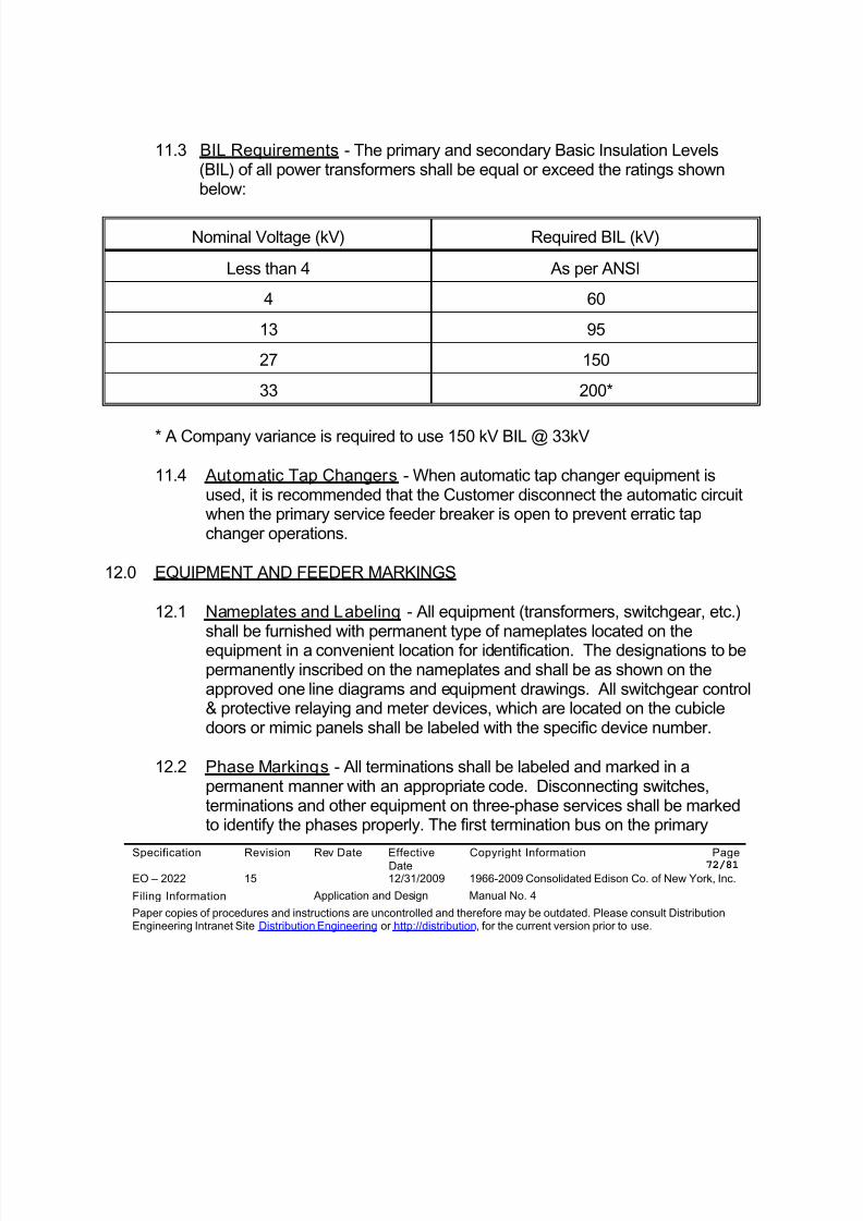
8/10/2019 Con Ed High Tension_EO-2022 (1)
http://slidepdf.com/reader/full/con-ed-high-tensioneo-2022-1 72/81
Specification Revision Rev Date EffectiveDate
Copyright Information Page 72/81
EO – 2022 15 12/31/2009 1966-2009 Consolidated Edison Co. of New York, Inc.
Filing Information Application and Design Manual No. 4
Paper copies of procedures and instructions are uncontrolled and therefore may be outdated. Please consult DistributionEngineering Intranet Site Distribution Engineering or http://distribution, for the current version prior to use.
11.3 BIL Requirements - The primary and secondary Basic Insulation Levels(BIL) of all power transformers shall be equal or exceed the ratings shownbelow:
Nominal Voltage (kV) Required BIL (kV)
Less than 4 As per ANSI
4 60
13 95
27 150
33 200*
* A Company variance is required to use 150 kV BIL @ 33kV
11.4 Automatic Tap Changers - When automatic tap changer equipment isused, it is recommended that the Customer disconnect the automatic circuitwhen the primary service feeder breaker is open to prevent erratic tapchanger operations.
12.0 EQUIPMENT AND FEEDER MARKINGS
12.1 Nameplates and Labeling - All equipment (transformers, switchgear, etc.)shall be furnished with permanent type of nameplates located on theequipment in a convenient location for identification. The designations to bepermanently inscribed on the nameplates and shall be as shown on theapproved one line diagrams and equipment drawings. All switchgear control& protective relaying and meter devices, which are located on the cubicledoors or mimic panels shall be labeled with the specific device number.
12.2 Phase Markings - All terminations shall be labeled and marked in apermanent manner with an appropriate code. Disconnecting switches,terminations and other equipment on three-phase services shall be markedto identify the phases properly. The first termination bus on the primary
8/10/2019 Con Ed High Tension_EO-2022 (1)
http://slidepdf.com/reader/full/con-ed-high-tensioneo-2022-1 73/81
Specification Revision Rev Date EffectiveDate
Copyright Information Page 73/81
EO – 2022 15 12/31/2009 1966-2009 Consolidated Edison Co. of New York, Inc.
Filing Information Application and Design Manual No. 4
Paper copies of procedures and instructions are uncontrolled and therefore may be outdated. Please consult DistributionEngineering Intranet Site Distribution Engineering or http://distribution, for the current version prior to use.
service should be so connected that the phase designations are A-B-C whenfacing the front of the switchgear and reading from left to right.
12.3 Terminal Blocks and Wire Markings - To facilitate maintenance and
installation, all control, alarm and protective relaying wiring and terminalstrips shall be marked with permanent type markers in accordance with wireand terminal block designations as shall be noted on the wiring diagrams.See MES-350 for Revenue Metering wiring requirements.
13.0 PROOF TESTS
13.1 Primary Service Feeder Cable, Bus Potheads and Equipment - TheCompany and Customer's primary service feeder cable shall be tested, fromtime to time, at the voltage and duration values stated in latest revision ofCompany specification EO-4019. During the proof test the circuit breaker will
be racked-out or disconnect switch will be opened to isolate the Customer'sequipment; however, any Customer equipment connected on the line side ofthe circuit breaker or disconnect switch will be subjected to the Company'sproof testing values as stated in EO-4019. The Customer's potentialtransformers or other equipment will not be disconnected prior to the test andtherefore shall be sized to meet the Company's proof test values. The prooftest shall be witnessed by the Company's Field Engineer.
13.2 Customer Cable and Switchgear - The Customer shall perform andsubmit to the Company for record, results of cable, switchgear andequipment Proof Tests, performed at the site, for all equipment connected
after primary service feeder potheads. Proof tests shall be in accordancewith the latest IEEE (ANSI) standards and manufacturer'srecommendations. At the Customers request, the Company willrecommend proof test values; however, Company's proof test values areusually more stringent than the manufacturer’s recommendations. Prooftest are required for:
13.2.1 All new installations.
13.2.2 After a service or proof test failure resulting from a fault on theCustomer's installation.
8/10/2019 Con Ed High Tension_EO-2022 (1)
http://slidepdf.com/reader/full/con-ed-high-tensioneo-2022-1 74/81
Specification Revision Rev Date EffectiveDate
Copyright Information Page 74/81
EO – 2022 15 12/31/2009 1966-2009 Consolidated Edison Co. of New York, Inc.
Filing Information Application and Design Manual No. 4
Paper copies of procedures and instructions are uncontrolled and therefore may be outdated. Please consult DistributionEngineering Intranet Site Distribution Engineering or http://distribution, for the current version prior to use.
13.2.3 Before re-energizing cable or equipment which has not been inservice for one year or longer.
13.2.4 After upgrading or adding new or spare equipment, enclosed wiring,or other work disturbing the insulation of the existing equipment orwiring.
13.2.5 After work which involves removal of tanks or equipment accesscovers.
13.3 Power Transformers - Customer's power transformers shall be subject to ahigh potential proof test at the project site. The power transformermanufacturer’s recommended values shall be used for the proof tests.
14.0 APPROVAL OF PROJECT DRAWINGS AND DOCUMENTS
14.1 Review Items: Ini tial Project Stage - The Customer is required to submitfor Company record, review and approval, at the beginning stage of theproject, the following:
14.1.1 A signed copy of the General Requirements for Service to HighTension Customers … EO-2022 General Revision12.
14.1.2 A signed copy of the High Tension Technical Specification(DE Specification No. assigned by Customer Service) based on EO-2022,Technical Revision 13.
14.1.3 Six copies of a site specific (not typical), Engineering Consultant's
One Line Diagram, which shall include Project Name & Location inthe Title Box, date and revision number, approval signature andshall show quantity of each item, where more than one item issupplied. The One Line diagram shall be based on the AmericanSociety of Mechanical Engineers Electrical and Electronic
8/10/2019 Con Ed High Tension_EO-2022 (1)
http://slidepdf.com/reader/full/con-ed-high-tensioneo-2022-1 75/81
Specification Revision Rev Date EffectiveDate
Copyright Information Page 75/81
EO – 2022 15 12/31/2009 1966-2009 Consolidated Edison Co. of New York, Inc.
Filing Information Application and Design Manual No. 4
Paper copies of procedures and instructions are uncontrolled and therefore may be outdated. Please consult DistributionEngineering Intranet Site Distribution Engineering or http://distribution, for the current version prior to use.
Diagrams drafting practices - USAS Y14.15 - 1966 and thesupplement Y14.15a - 1971and shall include the following:
a. Power Transformers (primary and secondary voltage, power
rating, impedance and phasor diagram)
b. Voltage & Current Transformers (connections and ratios)
c. Circuit Breakers and Loadbreak Disconnect Switches(continuous current, symmetrical MVA ratings, and status -(N.O./N.C.)
d. Fuses and their ratings
e. Revenue Metering Transformers and Phasing Receptacles
f. Surge Arrester Characteristics, Control Switches, Neonindicators and Voltage and Current Instruments
g. Bus and Cable ratings
h. Grounding Devices and Ground Studs
i. Relaying (device No. and tripping direction) and shall showthe full contact development.
j. Interlocking (mechanical & electrical)
k. Generators (type, use, size, connections and impedances)
l. Customer feeder destinations and Special Operating Detailsincluding ATS logic and signal direction.
14.2 Review Items: Design Stage - During the design stage of the project theCustomer shall submit the following:
8/10/2019 Con Ed High Tension_EO-2022 (1)
http://slidepdf.com/reader/full/con-ed-high-tensioneo-2022-1 76/81
Specification Revision Rev Date EffectiveDate
Copyright Information Page 76/81
EO – 2022 15 12/31/2009 1966-2009 Consolidated Edison Co. of New York, Inc.
Filing Information Application and Design Manual No. 4
Paper copies of procedures and instructions are uncontrolled and therefore may be outdated. Please consult DistributionEngineering Intranet Site Distribution Engineering or http://distribution, for the current version prior to use.
14.2.1 A revised One Line diagram which shall include comments made onthe initial submittal.
14.2.2 A.C./D.C. schematic diagrams of the protection and control circuits.
14.2.3 Bill of Materials - including all relays, voltage & current transformers(showing ratios and connections) fuses and interrupting & groundingdevices
14.2.4 A relay coordination study and proposed protective relay settings.
14.2.5 Metering compartment equipment showing the physical layout &clearances, barriers and phasing facilities.
14.2.6 Bus, Cables & Terminations; (manufacturer's specifications).
14.2.7 Ground & Test Devices and Ground Switches; manufacturer,detailed description of operation, equipment drawings,specifications and interlocks.
14.2.8 Equipment room layouts (detailing all clearances) and the siteplans.
14.2.9 DC system One Line diagrams, detailing the battery and chargertypes, distribution panels, transfer switches, relaying and alarms.
14.2.10 Vendor drawings, specifications and Vendor documentation shallbe reviewed by the Customer prior to submittal to the Company.
14.2.11 Emergency Generator; interlocking procedures, load to be suppliedand testing schedule.
14.3 Review Items: Prior to Energization - Prior to energization the Customershall resubmit all drawings corrected and marked FINAL and stamped by aProfessional Engineer for Company record. The project site will be inspectedby Company personnel, from time to time, to verify compliance with Company
8/10/2019 Con Ed High Tension_EO-2022 (1)
http://slidepdf.com/reader/full/con-ed-high-tensioneo-2022-1 77/81
Specification Revision Rev Date EffectiveDate
Copyright Information Page 77/81
EO – 2022 15 12/31/2009 1966-2009 Consolidated Edison Co. of New York, Inc.
Filing Information Application and Design Manual No. 4
Paper copies of procedures and instructions are uncontrolled and therefore may be outdated. Please consult DistributionEngineering Intranet Site Distribution Engineering or http://distribution, for the current version prior to use.
specifications. The Customer shall also submit for review and approval thefollowing:
14.3.1 Certified relay test data including the date of test and all voltage and
current transformer ratios.
14.3.2 An Operating Specification which shall detail all operations undernormal and contingency modes of operations.
14.3.3 Certified Customer equipment High Potential Proof Test data andequipment operation test results. Operation tests shall include allinterrupting and grounding devices and the successful operation shallbe witnessed by the Company's Field Engineering Representative.
14.3.4 The Company will verify that the Customer's equipment nameplates
and phase markings are as noted on the Customer's drawings.
14.3.5 The Company will verify that a laminated copy of the approved/finalone line diagram and UC drawing is posted in the appropriatelocation(s).
14.3.6 The Company will verify that the Key storage lock box is on site.
14.3.7 The Company will verify that the Grounding device, tripping operation,interlocking system is functioning as required.
14.3.8 The Customer shall have the conduits or building attachmentscompleted and in place to accept the telephone service.
14.3.9 The Company will verify if Revenue Metering system is in place andready for operation.
14.4 Energization - Energization will be permitted only after the successfulcompletion of all Company and Customer specification requirements and a
finalized Customer written/Company approved System OperationSpecification is accepted. The System Operation Specification shall includeall normal and contingency modes of operation, including which switches are
8/10/2019 Con Ed High Tension_EO-2022 (1)
http://slidepdf.com/reader/full/con-ed-high-tensioneo-2022-1 78/81
Specification Revision Rev Date EffectiveDate
Copyright Information Page 78/81
EO – 2022 15 12/31/2009 1966-2009 Consolidated Edison Co. of New York, Inc.
Filing Information Application and Design Manual No. 4
Paper copies of procedures and instructions are uncontrolled and therefore may be outdated. Please consult DistributionEngineering Intranet Site Distribution Engineering or http://distribution, for the current version prior to use.
open and closed and which indicating lights will be on or off. The SystemOperation Specification shall include but not limited to:
Planned Outages on a primary service feeder.
Fault on the line side of a primary service feeder. Fault on the load side of a primary service feeder.
The Customer shall submit all finalized documents including as built drawings. TheCompany will perform the required proof test on the primary service feeders up toand including the Customer's feeder terminations (see Proof Test Section 13.0).
15.0 LIST OF COMPANY REFERENCES
EO-2012 Application of Lightning Arresters on Overhead Distribution Systems- Manual 4
EO-2034 Electric and Gas Services to DC Railroad Properties - Manual 4
EO-2034 Closed Transition Transfer From and To Con Edison's Supply
EO-4019 Proof Testing and Ammeter Clear Testing of Feeders and FeederMains - Manual 5
EO-4035 Operation and Maintenance of Equipment on High TensionCustomer's Premises - Manual 5
EO-6025 Cable Arcproofing Procedures - Manual 3
EO-6224 Requirements for Installing Direct Buried Cable in Both Public andPrivate Streets - Manual 3
EO-2468-B Cable Manhole Drawing - Manual 3
EO-3299-D Low Voltage Phasing Facilities Drawing for Three Phase, Three WireHigh Tension Feeders - Manual 5
8/10/2019 Con Ed High Tension_EO-2022 (1)
http://slidepdf.com/reader/full/con-ed-high-tensioneo-2022-1 79/81
Specification Revision Rev Date EffectiveDate
Copyright Information Page 79/81
EO – 2022 15 12/31/2009 1966-2009 Consolidated Edison Co. of New York, Inc.
Filing Information Application and Design Manual No. 4
Paper copies of procedures and instructions are uncontrolled and therefore may be outdated. Please consult DistributionEngineering Intranet Site Distribution Engineering or http://distribution, for the current version prior to use.
EO-3477-D Low Voltage Phasing Facilities Drawing for Three Phase, Four WireHigh Tension Feeders - Manual 5
EO-6130-C Cable Duct for Manhole Entrance Drawing, P/O EO-1042 - Manual 6
EO-3079-C Neon Tube Installation Drawing for Bus Type - Manual 5
EO-3782-C Low Voltage Phasing Facilities Drawing for Three Phase, Four WireHigh Tension Feeders when Two Voltage Transformers are used -Manual 5
MES-350 High Tension Metering Installations
MES-273-A Wiring Diagram for 13 kV Metering
MES-273-B Wiring Diagram for 27 kV & 33 kV Metering
MES-166-A Wiring Diagram for 2.4/4kV 3 phase 4 wire Metering
MES-731 and 731-A Layout and Wiring for Demand Recorder Metering
MES-712 and 712-A Layout and Wiring for Panel Mount HT Metering with NetworkLow Tension Auxiliary
MES-713 and 713-A Layout and Wiring for Panel Mount HT Metering with RadialLow Tension Auxiliary
The Company's "General Instructions Governing Work on System ElectricalEquipment."
The Company’s Blue Book - Requirements for Electric Service Installations
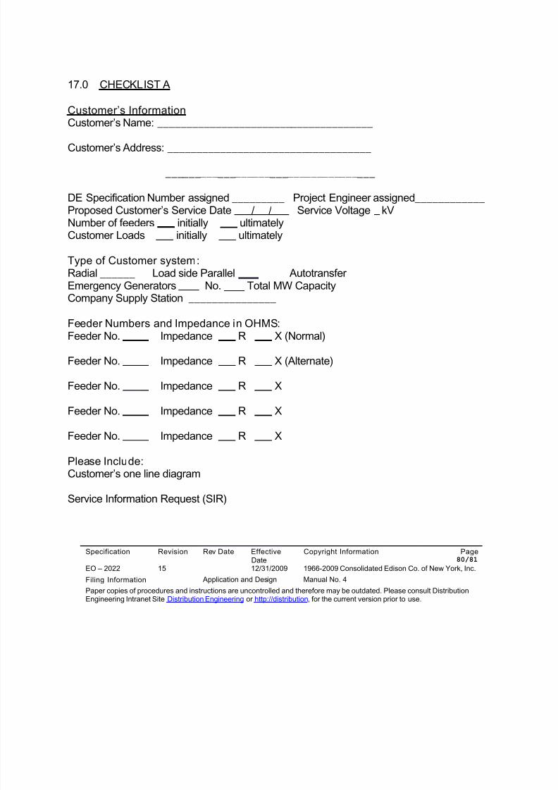
8/10/2019 Con Ed High Tension_EO-2022 (1)
http://slidepdf.com/reader/full/con-ed-high-tensioneo-2022-1 80/81
Specification Revision Rev Date EffectiveDate
Copyright Information Page 80/81
EO – 2022 15 12/31/2009 1966-2009 Consolidated Edison Co. of New York, Inc.
Filing Information Application and Design Manual No. 4
Paper copies of procedures and instructions are uncontrolled and therefore may be outdated. Please consult DistributionEngineering Intranet Site Distribution Engineering or http://distribution, for the current version prior to use.
17.0 CHECKLIST A
Customer’s InformationCustomer’s Name: _____________________________________
Customer’s Address: ___________________________________
____________________________________
DE Specification Number assigned _________ Project Engineer assigned____________Proposed Customer’s Service Date / / Service Voltage kVNumber of feeders initially ultimatelyCustomer Loads initially ultimately
Type of Customer system:
Radial ______ Load side Parallel AutotransferEmergency Generators No. Total MW CapacityCompany Supply Station _______________
Feeder Numbers and Impedance in OHMS:Feeder No. Impedance R X (Normal)
Feeder No. Impedance R X (Alternate)
Feeder No. Impedance R X
Feeder No. Impedance R X
Feeder No. Impedance R X
Please Include:Customer’s one line diagram
Service Information Request (SIR)
8/10/2019 Con Ed High Tension_EO-2022 (1)
http://slidepdf.com/reader/full/con-ed-high-tensioneo-2022-1 81/81
18.0 CONTRACT ACCEPTANCE
Customer Specification No. DE............................................................
Service Location: ........................................................................................................................................................................................................................................................................................................................
Consolidated Edison Company of New York Inc.
Date ...............................................
Company representative..........................................................................
Title ...........................................................................................................
Customer contract acceptance
Date ..............
Customer duly authorized representative: .........................................................
Title ......................................................................................................................