computational analysis of 2d aerospike nozzle with base
TRANSCRIPT

Turkish Journal of Computer and Mathematics Education Vol.12 No.10 (2021), 5878-5888
Research Article
5878
Computational Analysis Of 2d Aerospike Nozzle With Base Bleed At Different Altitudes
Santhosh Kumara*, Mouli Bhaskarb, Manur Gautamc, Bhanu Prakashd, Sarath Kumare
a,b,c,d Student, School of Aeronautical Sciences, Hindustan Institute of Technology & Science, Chennai, India e Assistant Professor, School of Aeronautical Sciences, Hindustan Institute of Technology & Science, Chennai, India
Article History: Received: 10 January 2021; Revised: 12 February 2021; Accepted: 27 March 2021; Published online: 28
April 2021
Abstract:
In the present-day scenario, several nozzles are being developed to achieve better efficiency. Among them, the aerospike is one
such nozzle. The aerospike nozzles are yet to be utilized in the aerospace sector but are believed to exhibit better performance
than the conventional bell-shaped nozzles that are currently in service. The geometry of the aerospike nozzle enables it to adjust
to its environment by modifying its outer jet boundary thus, making it more efficient than the other types of nozzles.
Simple approximation method is used to get the coordinates of the nozzle contour using MATLAB. To compare the
performance characteristics, both full and truncated spike nozzles were designed using SOLIDWORKS. In order to improve
the performance of the truncated aerospike nozzles, they are provided with base bleeds. The flow behaviour was analysed using
Computational Fluid Dynamics (CFD) software – ANSYS. These designs were simulated for different pressure outlet
conditions, to compare the performance of full length, truncated spike with and without base bleed, at different altitudes.
Keywords: aerospike nozzle, plug, truncation, cowl-lip, barrel shock, CFD.
Nomenclature:
µ Mach Angle
ν Prandtl – Meyer function
l Length of the Characteristic line
A_R Nozzle Expansion ratio
α Angle between characteristic line and sonic flow
λ 𝑙
𝑙𝑡,Non-dimensional length for plane nozzle
S Surface area
𝐴𝑡 Nozzle throat area
𝐴𝑒 Nozzle exit area
𝜂𝑏 Non–Dimensional base radius
ξ 𝑙
𝑟𝑒, Non-Dimensional length of axisymmetric nozzle
M Mach Number
γ Ratio of specific heats
Subscripts
t throat
e exit area
b base
Introduction:
Over the past few decades, mankind has shown immense potential in the field of aerospace. A key concept in the
exploration of space is the advancement in aerospace technology. In an aircraft, a nozzle plays a crucial role across
which the potential energy of the fluid is converted into kinetic energy, thus providing sufficient space for the
expansion of gases. Nozzles are mechanical devices that control the flow and direction of exhaust gases [1].
Different types of nozzles are used depending upon the requirement and operating conditions. Presently a
Convergent-Divergent (CD) nozzle is used predominantly for space missions. The CD nozzle has its drawbacks.
A typical CD nozzle requires huge space to fit into the engine and the fluid flow across the nozzle tends to separate
at the walls, thus reducing its performance. One of the nozzles that are being developed to overcome such problems
is the Aerospike nozzles. Aerospike nozzles are altitude compensating nozzles with shortened nozzle length for
the same or increased performance. Aerospike nozzles are often referred to as an Inside-out bell-shaped nozzle [2-
3]. This nozzle was developed in the view of Single Stage to Orbit (SSTO) vehicles.
While operating CD nozzles at low altitudes, if the exit pressure is lesser than the ambient pressure, the flow gets
radially compressed inwards resulting in the separation of flow at walls of nozzle and thus decreasing the efficiency
[3-4]. At higher altitudes, the ambient pressure will be very low which results in the flow expanding past the nozzle.
In an aerospike nozzle, the expansion process will begin at a point on the outer edge of the annulus known as the
cowl-lip. The combusted gases are directed towards the axis of the nozzle [4]. The gases exiting from the spike are
not enclosed by an external boundary. If an aerospike nozzle is operated in an over-expanded mode, the flow gets
imparted on the spike and thus maintains its efficiency. If an aerospike nozzle is operated in an under-expanded

COMPUTATIONAL ANALYSIS OF 2D AEROSPIKE NOZZLE WITH BASE BLEED AT DIFFERENT ALTITUDES
5879
mode, since the flow is not enclosed by any boundary, the thrust gets imparted on the centre spike and maintains
its efficiency. As there is an increase in altitude, the aerospike nozzle maintains a better aerodynamic efficiency
throughout the trajectory. Because of this reason, it is also termed as an Altitude-Compensating nozzle. Aerospike
nozzles produce a higher thrust efficiency and better average specific impulse since it makes better use of the base
area. Up to 25% of the fuel is saved if a vehicle is operated with an aerospike nozzle at low altitudes. Overall
performance of the aerospike nozzle is better than the conventional bell-shaped (CD) nozzle [4].
The main drawback of an aerospike nozzle is its unsustainability at high temperatures. Since the hot gases after
the combustion reach the nozzle at very high temperatures, the sharp edge of the nozzle (spike) cannot resist.
Truncation of the spike has been done to overcome this issue. In truncated aerospike nozzles, the specified length
of the spike will be removed which results in a flat base [5-7]. Due to high ambient pressure at low altitudes, the
gases at the exhaust remain close to the nozzle wall and it is said to be operating in open-wake conditions as shown
in Fig. 1a. At high altitudes, the ambient pressure will be very low which might cause an under expansion. But due
to the formation of barrel shock and trailing shock within the exhaust flow, it retains a column shape (which forms
at the design altitude) under the close wake condition as shown in Fig. 1b.
Fig. 1a Flow phenomenon of an over-expanded truncated aerospike nozzle.
Fig. 1b Flow phenomenon of an under-expanded truncated aerospike nozzle.
As the altitude increases, there will be a loss in performance for a truncated aerospike nozzle. These losses can be
balanced by introducing base bleed. From the base region, a secondary flow is implemented [4].
This paper compares the performances of full-length aerospike nozzle and truncated aerospike included with base
bleed at different altitudes. Mach contours of all the nozzles and the pressure plots for different truncations of the
nozzle were discussed.
Methodology
1. Nozzle Contour Design
The technique used to design the nozzle contour is the approximation method which is based on the method of
characteristics. The method of characteristics takes the inviscid assumption for devising the governing equations.
The method used in this paper is similar to the one used by Angelino [8].

Santhosh Kumara*, Mouli Bhaskarb, Manur Gautamc, Bhanu Prakashd, Sarath Kumare
5880
Along the characteristic lines, the derivatives blow up to be of an indeterminate form and may be discontinuous.
The contour is designed by considering a point from where the characteristic lines originate. This point acts as the
tip of the cowl and its position is user-defined. The characteristic line corresponding to the throat of the nozzle is
referred to as a sonic line since the Mach number at the throat is unity. The characteristic lines originating from
the tip of the cowl are inclined at an angle with respect to the sonic flow and are given by, α = µ - ν, where µ and
ν correspond to the Mach angle and Prandtl Meyer function respectively [9].
The value of µ is given by, µ = arcsin(1
𝑀), and
the Prandtl Meyer expansion function is given by
𝜈(𝑀) = √𝛾 + 1
𝛾 − 1 𝑎𝑟𝑐𝑡𝑎𝑛√(
𝛾 − 1
𝛾 + 1) (𝑀2 − 1) − 𝑎𝑟𝑐𝑡𝑎𝑛√𝑀2 − 1
The characteristic lines cross the required contour boundary at a distance l from the cowl lip. The distance l can be
computed by using the continuity equation
𝑙
𝑙𝑡= (
𝐴
𝑠𝑖𝑛𝜇) (
1
𝐴𝑡) (1)
where A is equal to the area normal to the velocity vector and 𝑙𝑡 is defined as the distance between the nozzle
contour boundary and cowl lip. The above equation can also be written as
𝜆 = (𝐴_𝑅) ∗ 𝑀 (2)
where A_R is defined as the nozzle expansion ratio.
In the above set of formulae, the Mach number values are to be varied in ascending order starting from 1 to the
desired exit Mach number [8]. For each value of the Mach number, the values of µ, ν, α, and area ratio are recorded.
In the below figure [8], a sonic flow is present at the throat of the nozzle. The characteristic lines originating from
the cowl lip are straight and follow the two-dimensional law.
From the figure we have,
𝑆 = 2𝜋 𝑟ₑ+𝑟
2
𝑟ₑ−𝑟
𝑠𝑖𝑛𝛼 (3)
Where S is defined as the surface area crossed by the flow.
Fig. 2 Schematic diagram of two-dimensional Aerospike nozzle
The velocity vector makes an angle µ with the surface, thus the actual area becomes
𝐴 = 𝑆 𝑠𝑖𝑛𝜇 =𝑟𝑒−𝑟
𝑀 𝑠𝑖𝑛𝜇 (4)
Furthermore, the length of the characteristic line is given by
𝑙 =𝑟𝑒−𝑟
𝑠𝑖𝑛𝛼 (5)
The exit area of the nozzle is given by
𝐴𝑒 = 𝜋(𝑟𝑒2 − 𝑟𝑏
2)
For the case of full truncation aerospike nozzle, 𝑟𝑏 will be equal to zero.
Keeping equation (5) in mind, equation (4) can be rewritten as
𝑙 = 𝑟𝑒−√𝑟𝑒
2− 𝐴 𝑀 𝑠𝑖𝑛𝛼
𝜋
𝑠𝑖𝑛𝛼 (6)
The above equation can be non-dimensionalized with respect to the exit radius of the spike. Thus, the transformed
equation becomes
𝜉 = 𝑙
𝑟𝑒=
1−(1−(𝐴_𝑅𝑖(1−𝜂𝑏2) 𝑀
𝑠𝑖𝑛𝛼
𝐴_𝑅))
𝑠𝑖𝑛𝛼 (7)
Here 𝜂𝑏is defined as the non-dimensional base radius [8].

COMPUTATIONAL ANALYSIS OF 2D AEROSPIKE NOZZLE WITH BASE BLEED AT DIFFERENT ALTITUDES
5881
With the help of the above set of relations, each coordinate of the nozzle contour is computed independently, thus
providing greater accuracy.
MATLAB code for nozzles is prepared with the help of the thesis [10] and analysis has been carried out for
different truncations. The amount of truncation is mentioned in the code itself. In this paper length truncation of
aerospike nozzle has been carried out for 15%, 30% along with base bleeds. The input parameters for geometry
are taken from [10], and the ratio of specific heats is chosen for Liquid Oxygen & Liquid Hydrogen based on the
mixture ratio [11]. Input parameters for design are:
• The ratio of specific heats: 1.203
• Area ratio: 6.8214
• Tube diameter: 3.2036
The geometry is developed using SOLIDWORKS from the generated MATLAB code. The analysis is done using
the CFD software Ansys Student. The outlet and far-field distance from the tip of the plug are 10 & 5 times the
exit diameter to the X & Y-axis respectively. Since the nozzle flow is axisymmetric and to reduce the
computational time, the upper half of the nozzle is only designed for analysis. Fig. 3 shows the spike contour of a
full-length nozzle generated from code.
Fig. 3 Plug contour generated from MATLAB
2. Grid Generation
To facilitate different initial conditions in each region, the domain has been divided into 4 regions. Multizone
Quad/tri meshing is used to the entire domain to improve the overall quality of the mesh [12]. The intensity of the
grid is more near the plug wall to capture the variable gradients. A grid independence study was done and found
the number of cells to be around 40000. The meshing is done accordingly for all designs.
3. Fluent setup
The flow is assumed to be a steady, viscous, and ideal gas. The density-based model with the K-Omega SST
turbulence method is used for the better prediction of flow behaviour. The boundary conditions for various regions
are taken as shown in table 1. For base bleed, a secondary inlet is provided which is of the velocity-type. The
magnitude of fluid velocity at the secondary inlet is taken as 80 m/s. Since the analysis is being done for cold flow,
the outlet, far-field and the chamber temperatures are maintained at 300 K.

Santhosh Kumara*, Mouli Bhaskarb, Manur Gautamc, Bhanu Prakashd, Sarath Kumare
5882
The coupled implicit linearization with second-order upwind discretization is used for the solution of governing
equations [13]. Courant number (CFL number) has been set to 1 for all cases.
Fig. 4 Solution domain and regions
Table 1: Boundary conditions
Altitude(m) Chamber Pressure (Pa) Pressure Far-field (Pa) Outlet Pressure (Pa)
0 6079500 101325 101325
10400 6079500 24856.4 24856.4
19000 6079500 6410 6410
36000 6079500 509.14 509.14
100000 6079500 1 1
Results & Discussion:
In this section, the performance analysis of different nozzles is compared through Mach contours and static
pressure plots at various altitudes.

COMPUTATIONAL ANALYSIS OF 2D AEROSPIKE NOZZLE WITH BASE BLEED AT DIFFERENT ALTITUDES
5883
(a) At Sea level (b) At 10400 m
(c) At 19000 m (d) At 36000 m
(e) At 100000 m
Fig. 5 Mach contours of full-length plug nozzle at different altitudes
From the fig. 5, it can be seen that the exhaust fluid undergoes expansion process and bulges outward with the
increase in altitude. The exit Mach number at the end of the spike also increases with the increase in altitude. At
higher altitudes the expansion waves originating from the cowl-lip causes the flow to encounter a sharp expansion,
thus resulting in higher Mach number region.

Santhosh Kumara*, Mouli Bhaskarb, Manur Gautamc, Bhanu Prakashd, Sarath Kumare
5884
(a) At sea level (b) At 10400 m
(c) At 19000 m (d) At 36000 m
(e) At 100000 m
Fig. 6 Mach contours of 15% truncated plug nozzle at different altitudes
By truncating full length nozzle to 15% it can be observed that the expansion of jet is even stronger due to the
truncated portion of the nozzle. The truncation of the spike results in shorter distance and the expansion waves
originating from the plug encounters another expansion wave caused by the expansion of the flow at the tip of the
truncated portion of the plug. This phenomenon can be observed at higher altitudes i.e., fig. 6.
COMPUTATIONAL ANALYSIS OF 2D AEROSPIKE NOZZLE WITH BASE BLEED AT DIFFERENT ALTITUDES
5885
(a) At sea level (b) At 10400 m
(c) At 19000 m (d) At 36000 m
(d) At 100000 m
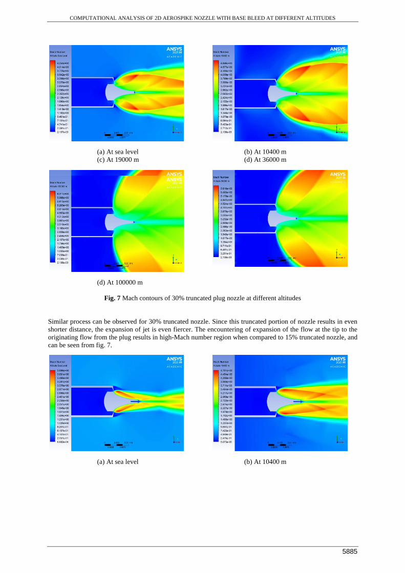
Fig. 7 Mach contours of 30% truncated plug nozzle at different altitudes
Similar process can be observed for 30% truncated nozzle. Since this truncated portion of nozzle results in even
shorter distance, the expansion of jet is even fiercer. The encountering of expansion of the flow at the tip to the
originating flow from the plug results in high-Mach number region when compared to 15% truncated nozzle, and
can be seen from fig. 7.
(a) At sea level (b) At 10400 m

Santhosh Kumara*, Mouli Bhaskarb, Manur Gautamc, Bhanu Prakashd, Sarath Kumare
5886
(c) At 19000 m (d) At 36000 m
(e) At 100000 m
Fig. 8 Mach contours of 15% truncated plug nozzle with base bleed of velocity 80m/s at different altitudes
The flow structure at the base changes drastically with the introduction of base-bleed, because of the interaction
of subsonic and supersonic flows, resulting in a better converged flow in comparison with no base bleed nozzle.
These changes can be seen from comparing fig. 8 (a) and fig. 6 (a). The effect of base-bleed is significantly less
for higher altitude.
(a) At sea level (b) At 10400 m

COMPUTATIONAL ANALYSIS OF 2D AEROSPIKE NOZZLE WITH BASE BLEED AT DIFFERENT ALTITUDES
5887
(c) At 19000 m (d) At 36000 m
(e) At 100000 m
Fig. 9 Mach contours of 30% truncated plug nozzle with base bleed of velocity 80 m/s at different altitudes
A similar trend is observed for 30% truncated nozzle with base bleed. When compared at the same altitude, with
the increase in truncation of the nozzle, the Mach number at the nozzle exit also increases. By introducing the base
bleed, the flow recirculation at the flat base is reduced, such that there will not be any sudden pressure drop at the
base of the nozzle. From figures 8, 9 & 6,7, it can be seen that the amount of variation in performance with the
introduction of the base bleed of velocity 80 m/s is significantly less.
(a) At sea level (b) At 10400 m

Santhosh Kumara*, Mouli Bhaskarb, Manur Gautamc, Bhanu Prakashd, Sarath Kumare
5888
(c) At 19000 m (d) At 36000 m
(e) At 100000 m
Fig. 10 Static Pressure change over the spike for different plug truncations at different altitudes
The above figure represents the pressure contours over the spike at different conditions. The flow coming out of
the throat experiences a huge loss in static pressure due to strong expansion. It is observed that the static pressure
over the spike of the nozzle does not significantly vary with respect to the altitude.
Conclusion:
Flow structure and performance of the truncated nozzles were compared. The static pressure variation over plug is
found to be very small with respect to altitude for different truncation ratios. The loss in performance due to under-
expansion at different altitudes is compensated by giving length truncation. Truncating the spike gave a significant
increase in Mach number at the exit of the nozzle, which can be observed for 15% and 30% truncation.
It is found that introducing lower base bleed velocities has no significant variation in the performance of the nozzle.
The higher base bleed velocities may compensate for the loss in thrust/performance due to under-expansion. It is
recommended to use truncated nozzles for better performance at higher altitudes of flight.
Based on the studied parameters, it can be concluded that the amount of truncation depends on the flight regime
and the propulsive system.
References:
1. Kumar, K. Naveen, et al. "Design and Optimization of Aerospike Nozzles using CFD." IOP Conference
Series: Materials Science and Engineering. Vol. 247. No. 1. IOP Publishing, 2017.
2. Nair, Prasanth P., Abhilash Suryan, and Heuy Dong Kim. "Study of conical aerospike nozzles with base-
bleed and freestream effects." Journal of Spacecraft and Rockets 56.4 (2019): 990-1005.
3. Ladeinde, Temitayo, and Hsun Chen. "Performance Comparison of a Full-Length and a Truncated
Aerospike Nozzle." 46th AIAA/ASME/SAE/ASEE Joint Propulsion Conference & Exhibit. 2010.
4. Bui, Trong, et al. "Flight research of an aerospike nozzle using high power solid rockets." 41st
AIAA/ASME/SAE/ASEE Joint Propulsion Conference & Exhibit. 2005.

COMPUTATIONAL ANALYSIS OF 2D AEROSPIKE NOZZLE WITH BASE BLEED AT DIFFERENT ALTITUDES
5889
5. Choudhari, Dipak J., and Uday V. Asolekar. "Efficiency analysis of an aerospike nozzle." International
Journal of Engineering Research and Applications (IJERA) ISSN (2012): 2248-9622.
6. Ajith, S., et al. "Performance Evaluation of Aerospike Nozzles for Lucrative Thrust Vector Control." 52nd
AIAA/SAE/ASEE Joint Propulsion Conference. 2016.
7. Takahashi, Hidemi, et al. "Aerodynamic characterization of linear aerospike nozzles in off-design flight
conditions." Journal of Propulsion and Power 31.1 (2015): 204-218.
8. Angelino, Gianfranco. "Approximate method for plug nozzle design." AIAA Journal 2.10 (1964): 1834-
1835.
9. Korte, J. J., et al. "Multidisciplinary approach to linear Aerospike nozzle design." Journal of Propulsion
and Power 17.1 (2001): 93-98.
10. Bani, Abdalla Ali. "Design and analysis of an axisymmetric aerospike supersonic micro-nozzle for a
refrigerant-based cold-gas propulsion system for small satellites." (2016).
11. http://www.braeunig.us/space/comb-OH.htm
12. Nazarinia, Mehdi, Arash Naghib-Lahouti, and Elhaum Tolouei. "Design and numerical analysis of
aerospike nozzles with different plug shapes to compare their performance with a conventional nozzle."
AIAC-11 Eleventh Australian International Aerospace Congress. 2005.
13. Guide, ANSYS FLUENT User. "Release 14.0, ANSYS." Inc., USA, November (2011).