comprehensive product platform planning (cp3) for a
TRANSCRIPT

COMPREHENSIVE PRODUCT PLATFORM PLANNING (CP 3) FOR A MODULARFAMILY OF UNMANNED AERIAL VEHICLES
Souma Chowdhury ∗
Syracuse UniversitySyracuse, NY, 13244
Email: [email protected]
Victor Maldonado †
Texas Tech UniversityLubbock, Texas, 79409
Email: [email protected]
Weiyang TongSyracuse University
Syracuse, NY, 13244Email: [email protected]
Achille Messac ‡
Syracuse UniversitySyracuse, NY, 13244
Email: [email protected]
ABSTRACTThe development of products with a modular structure,
where the constituent modules could be derived from a set ofcommon platforms to suit different market niches, providesunique engineering and economic advantages. However, thequantitative design of such modular product platforms couldbecome significantly challenging for complex products. TheComprehensive Product Platform Planning (CP3) methodfacilitates effective design of such product platforms. The orig-inal CP3 method is however typically suitable for scale-basedproduct family design. In this paper, we perform importantmodifications to the commonality matrix and the commonalityconstraint formulation in CP3 to advance its applicability tomodular product family design. A commonality index (CI),defined in terms of the number of unique modules in a family, is
∗Research Assistant Professor, Department of Mechanical and Aerospace En-gineering, ASME Member.
†Post-Doctoral Fellow, Department of Mechanical Engineering, ASMEMember.
‡Distinguished Professor and Department Chair. Department of Mechanicaland Aerospace Engineering, ASME Lifetime Fellow. Corresponding Author.
used to quantify the commonality objective. The new CP3 methodis applied to design a family of reconfigurable Unmanned AerialVehicles (UAVs) for civilian applications. CP3 enables thedesign of an optimum set of distinct modules, different groupsof which could be assembled to configure twin-boom UAVs thatprovide three different combinations of payload capacity andendurance. The six key modules that participate in the platformplanning are: (i) the fuselage/pod, (ii) the wing, (iii) the booms,(iv) the vertical tails, (v) the horizontal tail, and (vi) the fuel tank.The performance of each UAV is defined in terms of its rangeper unit fuel consumption. Among the best tradeoff UAV familiesobtained by mixed-discrete Particle Swarm Optimization, thefamily with the maximum commonality (CI=0.5) required a 66%compromise of the UAVs’ range/fuel-consumption performance.The platform configuration corresponding to the maximum-commonality UAV family involved sharing of the horizontal tailand fuel tank among all three UAVs and sharing of the fuselageand booms among two UAVs.
Keywords: Commonality Matrix, Modular Product Family,Platform, Reconfigurable, Unmanned Aerial Vehicle (UAV)
1 Copyright © 2013 by ASME
Proceedings of the ASME 2013 International Design Engineering Technical Conferences and Computers and Information in Engineering Conference
IDETC/CIE 2013 August 4-7, 2013, Portland, Oregon, USA
DETC2013-13181

INTRODUCTIONThedevelopment of a product line to satisfy different market
niches presents significant challenges to manufacturing indus-tries− fromproduct-conceptionto manufacturingto aftermarketservices. A product family with a common platform paradigmoffers a powerful solution to these daunting challenges. The shar-ing of common platforms by different products is expected toresult in: (i) reduced overhead and lower per product cost, (ii)streamlined supply chain, and (iii) shorter concept-to-shelf timefor new products [1]. From this perspective, the key to a success-ful product family is the effectiveness of the product platformsaround which the family is derived. Numerical optimization-based quantitative methods have been proven to be one of themost useful tools in product family design (PFD). Depending ontheir design architecture, product families have traditionally beenclassified as (1) modular (module-based), or (2) scalable (scalebased). In a scale-based product family, each individual productis generally comprised of the same set of physical design vari-ables. Different products in the family are developed by scalingthe non-platform features (design variables) such that each prod-uct satisfies a unique set of requirements. In a module-basedproduct family, distinct modules are added or substituted (on acommon platform) to develop different products [2, 3]. A pop-ular example of a modular product family is the series of SonyWalkmans [4,5], whereas a standard example of a scalable prod-uct family is Boeing’s 777 aircraft series [6]. In addition to theadvantages derived from the increased scope of platform plan-ning, modular product architecture also provides benefits such aseasier transportation, easier replacement of products, potentialfor reconfigurability, and effective evolution of product genera-tions.
However, modular product families generally presentgreater challenges to the design process owing to factorssuch as: (i) module-interdependency, (ii) possibility of inclu-sion/exclusion/replacement of modules, and (iii) definition ofeach module in terms of multiple variables (requiring simultane-ous variable evolution during platform-planning). Existing PFDmethods that address these challenges often make limiting as-sumptions such as: predefining which modules will be sharedamong product variants. On the other hand, scale-based prod-uct family methods that do not resort to this assumption are lim-ited in their scope of applicability to modular PFD. This paperpresents an advancement of the Comprehensive Product PlatformPlanning (CP3) method to design modular families that seeks toavoid such limiting assumptions. The objective of this paperis to translate the favorable quantitative attributes of CP3, such
as avoiding ”all-or-none assumption” and one-step scale-basedplatform planning, into the design of modular families. The ef-fectiveness of the modular CP3 method is then illustrated by de-signing a family of complexunmanned aerial vehiclesor UAVs(for civilian survey applications)
In this section, a brief survey of existing product family de-sign methodologies is provided, followed by an overview of theoriginal (CP3) method. The Section ends with a brief summaryof product family concepts in aircraft design, and the scope of itsapplicability (and benefits) to civilian UAVs.
Modular Product Family Design (PFD) MethodsTwo popular scale-based PFD approaches are: (i) thetwo-
step approach, and (ii) theexhaustive approach. A comprehen-sive list of differenttwo-stepmethods can be found in the bookchapter by Simpson [7]. Both these approaches make limitingassumptions that restrict their applicability to the broad scope ofproduct family design. A handful of new methods to design scal-able product families, which do not belong to the two broad cat-egories, have also been reported in the literature [8,9,10]; thesemethods address most of the limitations of the earlier methods,and also present other uniquely favorable characteristics. How-ever, a majority of these scale-based PFD methods do not read-ily apply to modular families. It is important to note that, themodifications proposed in this paper can also be applied (withminor variations) to the other recent/advanced scale-based PFDmethods, enabling them to effectively address modular familiesas well.
One of the popular approaches to module-based productfamily design conceptually divides the process into the followingthree levels (i) Architectural level: to establish a system struc-ture and its variations, (ii) Configuration level: to establish stan-dard configuration(s), and its variations of products and modules,and (iii) Instantiation level: to develop a practical product fam-ily through variable quantification and combinatorial selectionof the modules. In this paper, the instantiation level of modularPFD has been particularly addressed. The instantiation task levelis composed of the following two phases (i) Variable quantifica-tion: to develop modules across product prototypes by quantify-ing design variables; and (ii) Combinatorial selection: to developproduct prototypes by selecting desirable combinations from thefeasible ones. Based on these phases, approaches to the instanti-ation task level can be divided into the following three classes:
1. Optimization of module attributes under fixed module com-bination;
2. Optimization of module combinations using predefinedmodule candidates; and
3. Simultaneous optimization of module attributes and module
2 Copyright © 2013 by ASME
combinations.
The majority of the approaches for solving these optimizationproblems require specifying the platform (fixed module com-bination, i.e., Class 1) prior to optimization, in order to reducethe design space and render the problem computationally moretractable. Most other optimization approaches are geared towardClass 2 optimization problems, e.g., Ref. [11]. The assumptionsinvolved in these two classes may lead to sub-optimal module-based product families. Very few optimization approaches existto solve Class 3 type optimization problems, such as developedby Fujita et al. [12,13].
Several other well known methods exist in modular PFD,such as presented by Stone et al. [14], Dahmus et al. [15], Guo etal. [16], Jose et al. [17], Kalligeros et al. [18], Saron et al. [19],Yu et al. [20], and [21].
Comprehensive Product Platform Planning (CP 3):Overview
The Comprehensive Product Platform Planning (CP3)framework, introduced by Chowdhury et al. [22], seeks to coher-ently address a wide range of problem scenarios. The CP3 frame-work presents a generalized mathematical model of the platformplanning process based on the formulation of a commonality ma-trix. This model yields amixed-integer nonlinear programming(MINLP) problem with a large number of binary variables. Orig-inally, Chowdhury et al. [22] developed and implemented a Plat-form Segregating Mapping Function (PSMF) method to convertthe MINLP problem into a less expensive continuous optimiza-tion problem, and the approximated problem was solved usingconventional Particle Swarm Optimization (PSO). A reductionof the high-dimensional MINLP problem into a more tractableMINLP problem was later performed [23], and the reduced prob-lemwas solved using a mixed-discrete PSO algorithm [24].
Thecommonality matrix in the original CP3 method, as wellas other similar commonality formulations [25], do not readilyrepresent the platform-plan for modular products, where eachmodule comprisesmultiple design variables. This paper modi-fies the commonality matrix definition for application to modularfamilies. Subsequently, the commonality constraint, which en-sures feasible product platform plans, is also modified to enableeffective sharing of multivariate modules among product vari-ants. Importantly, the scaling attributes of the original CP3 modelare favorably retained, which is unique in the PFD literature. Im-portant features of this new modular CP3 model include:
1. This model facilitates sharing of entire multivariate modulesamong product variants.
2. Modules are allowed to be included or excluded, based onallowed physical product configurations.
3. If necessary (from a practical manufacturing standpoint), in-dividual design variables within particular modules are al-lowed to be independently shared or scaled (without neces-sitating the entire module to be shared or scaled correspond-ingly).
4. This model enables simultaneous identification of platform-ing modules and determination of the optimal module at-tributes (design variable quantification), during the productfamily optimization process.
The allowed physical combinations of modules is however as-sumed to be known, based on the product architecture; this as-sumption is generally valid for commercial products.
Product Family Concepts in Aircraft DesignProduct family methodologies in aircraft design are em-
ployed by some aircraft manufacturers to design a series of multi-mission capable aircraft with superior performance at a lowercost. Unlike the application of multidisciplinary design opti-mization (MDO) techniques to optimize a single aircraft for aspecific mission, product family aircraft designs are optimizedwith a certain degree of commonality while interchanging keycomponents in order to satisfy a wide range of mission require-ments. Historically, this has been accomplished though deriva-tives or variants of the baseline aircraft. For example, the originalBoeing 737-100 which first flew in 1967 has evolved (through 11major design variants in 39 years) in order to increase passengercapacity, fuel efficiency, and flight range. However, despite thesteady increase in performance, the Boeing 737 series continuesto operate primarily domestic routes. The goal of modern prod-uct family methods is to design aircraft with a significant varia-tion in performance in order to serve multiple market segments,i.e. domestic and transatlantic routes. Such a motivation is dis-cussed in the study by [26] to design a family of two blended-wing-body (BWB) aircraft with a capacity of 272 and 475 pas-sengers with built-in commonality. Other noteworthy investiga-tions includes the use of decomposition-based methods [27] andgenetic algorithm techniques [28] for aircraft family design.
In recent years, the academic community has seen an ex-plosive growth in research towards unmanned aerial vehicles(UAVs) fueled by sharp sales projections from a nascent CivilianUAV market. The industry now seeks to develop unmanned air-craft for a wide range of applications and mission profiles. Thispresents a unique opportunity to utilize product family methodsto design a modular UAV family that simultaneously meets theneeds of diverse customer requirements while reducing designand fabrication costs to the manufacturer. A methodology for thedesign of a two-UAV family operating under aerial firefightingin the vicinity of the Greek islands and maritime surveillance off
3 Copyright © 2013 by ASME

the coast of Norway is described by Freeman et al. [29]. How-ever, although the applications are different, both missions re-quire long endurance monitoring with similar camera payloads.Limited research has been done in leveraging modular productfamily concepts to allow reconfiguration of large-scale aircraftfeatures. One unique example is the work by Pate et al. [30], inwhich a family of reconfigurable aircraft was designed throughinterchangeable wings and engines. In the current paper, we con-sider a family of three UAVs designed to fulfill missions withdistinct endurance and payload/ weight requirements. Moreover,it becomes more profitable to both the manufacturer and the con-sumers (or end-users) when the UAV family is designed for in-dustries where the same end-user can take advantage of the mod-ular design and utilize all three UAV configurations.
ADVANCING CP3 FOR MODULAR PRODUCTSIn this Section, we describe the important modifications
made to the CP3 model to allow module-based platform plan-ning. The Section starts with the formulation of the new com-monality matrix and commonality constraint. Subsequently, weillustrate how one of the popular measures of commonality canbe readily derived from the new CP3 commonality matrix. TheSection ends with the formulation of the modular product familyoptimization problem that maximizes the inter-product common-ality, while maximizing the individual product performances.
Modification of the CP 3 ModelThe CP3 framework [22] introduced a compact mathemati-
cal model of the product family design problem. Key features ofthe original scale-based CP3 model are:
i. This model presents a generalized and compact mathemat-ical representation of the platform planning process, whichis independent of any optimization strategy.
ii. This model avoids the “all or none” restriction [9], therebyallowing the formation of sub-families of products.
iii. This model facilitates simultaneous (i) selection of plat-form/scaling design variables, and (ii) quantification of theoptimal design variable values.
In the original CP3 model, commonality was defined strictlyin terms of the product design variables. In this paper, we pro-vide the flexibility to define commonality among products bothin terms of individual design variables or modules (where eachmodule can be a collection of variables). “A product platform issaid to be created when more than one product variant in a familyshares a particular part.” In this case a part can be both a moduleor an individual design variable. Based on this concept, the com-monality among modular products is concisely represented using
the generalized matrix, calledcommonality matrix− representedby λ . For ease of illustration, we represent the commonality ma-trix in terms of module sharing/variation. Thecommonality ma-trix for a family of N products, comprised of a maximum ofmmodules, is given by
λ=
λ 111 · · · λ 1N
1 0 0 0 0 0 0 0 0...
...... 0 0 0 0 0 0 0 0
λ N11 · · · λ NN
1 0 0 0 0 0 0 0 0
0 0 0...
......
...... 0 0 0
0 0 0... λ 11
i · · · λ 1Ni
... 0 0 0
0 0 0...
......
...... 0 0 0
0 0 0... λ N1
i · · · λ NNi
... 0 0 0
0 0 0...
......
...... 0 0 0
0 0 0 0 0 0 0 0λ 11m · · · λ 1N
m
0 0 0 0 0 0 0 0...
......
0 0 0 0 0 0 0 0λ N1m · · · λ NN
m
λ kli =
{
1 , if λ kki = λ ll
i = 1 andXki = Xl
i0 , otherwise
}
∀ k 6= l
λ kki =
{
1 , if the ith module is included in product−k0 , if the ith module is not included in product−k
i = 1,2, . . . ,m; k, l = 1,2, . . . ,N(1)
In this matrix definition, the generic vectorXki represents theith
module in product-k, i.e., the vector of variables comprising theith module in product-k. Thecommonality matrixis a symmetricblock diagonal matrix, where theith block corresponds to theith
module. In the case of the original CP3 model, all the diagonal el-ements (λ kk
i ) were fixed at one− since all products variants werecomprised of the same set of physical design variables. However,in this new commonality matrix, the diagonal elements (λ kk
i ) areallowed to vary (during optimization) depending on the allowedproduct architecture (which is known a priori in practice). Thesebinary variables (λ kk
i ) are calledmodule-inclusion variables.The off-diagonal elements of thecommonality matrix, (λ kl
j ),
determine whether theith module is shared by product-k andproduct-l , whereλ kl
i = 1 if shared, andλ kl0 = 0 if not shared.
These off-diagonal elements are treated as binary variables dur-ing the optimization process, and are termed ascommonalityvariables[22]. If certain physical design variables (comprisingthemodules) need to be shared/scaled independently (for an ap-plication), the corresponding module-based commonality blocks
4 Copyright © 2013 by ASME
can be readily expanded into sub-blocks to account for such ascenario. In that case,λ kl
i j will determine whether thej th vari-
able in theith module is shared by product-k and product-l .Using the modified commonality matrix definition, we for-
mulate the newcommonality constraintfor modular products.The commonality constraintensures compatibility between theproduct platform planand thephysical design of each product.The newcommonality constraintis expressed as
m∑
i=1∑
∀k6=lµkl
i = 0
where
µkli =
{
λ kli
∣
∣Xki −Xl
i
∣
∣
2, if λ kk
i = λ lli = 1
0, otherwise
k, l = 1,2, . . . ,N
(2)
In this equation,∣
∣Xki −Xl
i
∣
∣
2=
(
Xki −Xl
i
)T (Xk
i −Xli
)
. The pa-rameterm represents the maximum number of physical modulesthat can form a single product variant. It is evident from Eq.2that each term in thecommonality constraint, µkl
i , becomes zeroonly if
1. theith module is not included in one or both products− inwhich case sharing is not possible; OR
2. theith module is shared by product-k and product-l ; OR3. the commonality variable is equal to zero, i.e.,λ kl
i = 0.
In the third case (above), theith module is generally not sharedby product-k and product-l .
The process of testing whether a product family (comprisingN products and a maximum ofmmodules) satisfies thiscommon-ality constraintis explained in Fig.1. In this figure, the blackarrows represent the process direction and the grey arrows rep-resent flow of information (as-needed basis). In Fig.1, the pa-rameter,M, is equal toN(N−1)/2; the tolerance parameter,ε,is used to relax the equality criterion into an inequality criterion− to allow manufacturing tolerances and/or to ease the optimiza-tion process. In Fig.1, the generic parameterXk represents theoverall design vector of product-k.
Commonality ObjectivesIn the product family design literature, the minimization
of the overhead costs (through product platform planning) isoften substituted by the maximization of a commonality mea-sure/metric that represents the net degree of inter-product com-monality. Among the proposed metrics that provide a measureof tooling cost savings attributed to component sharing, thecom-
monality indexdeveloped by Martin and Ishii [31] has been re-ported to be an effective metric [25]. This commonality indexisessentially based on the ratio of “the number of unique parts” to“the total number of parts” in the product family. For a familyof N product variants, thecommonality index(CI) can be mathe-matically defined as
CI = 1−u−max(nk)
N∑
k=1nk−max(nk)
(3)
whereu represents the actual number of unique parts in the wholeproduct family;nk represents the number of parts in thekth prod-uct. The “−max(nk)” term is included in the definition to ensurethat theCI varies between 0 and 1.
The total number of unique parts in a product family is equalto the rank of thecommonality matrixin CP3 [23]. Hence, a moregeneralized definition of the commonality index is given by
CI = 1−Rλ −mN∑
k=1nk−m
(4)
whereRλ is the rank of thecommonality matrixλ ; and nk isthe number of modules in thekth product;nk = m, ∀k, when allthe product variants are comprised of the same types of physicalmodules.
Optimization Problem FormulationEvery candidate product platform plan (in CP3) involves a
large number of binary integer variables− thecommonality vari-ablesand themodule-inclusion variables. Each block of thecommonality matrix(λi), corresponding to a module, is com-prised of
1. N(N−1)/2 commonality variables: λ kli (∀ k 6= l ); and
2. at most,N module-inclusion variables: λ kki .
In practice, the number ofmodule-inclusion variableswill be lessthanN, due to likely prior knowledge that certain modules cannotbe included/excluded from certain product variants (dependingon product architecture).
Owing to the transitivity constraints [25, 23], the common-ality variables(λ kl
i ’s) are however not necessarily independentof each other. The set of feasiblecommonality matricescanbe readily identified by applying the transitivity constraints toall the possiblecommonality matrixvariations as reported byChowdhury et al. [23]. In the case of a module-based family,
5 Copyright © 2013 by ASME

FIGURE 1. The process of applying thecommonality constraint
the possibility of module inclusion/exclusion/substitution posesadditional constraints on thecommonality variables, which canbe intuitively defined as:
λ kli ≤ λ kk
i λ lli , ∀ i = 1,2, . . . ,m; k, l = 1,2, . . . ,N (5)
This constraint ensures that a module sharing scheme (λ kli = 1) is
possible between any two products, if and only if the concernedmodule is included in these two products (λ kk
i = λ lli = 1).
In a scale-based family, the diagonal elements of thecom-monality matrixare all equal to one. With this consideration,Chowdhury et al. [23] aggregated theN(N− 1)/2 binary com-monality variables(in eachcommonality matrix block) into asingle binary string of length,L = N(N−1)/2; this string wassubsequently converted into an integer variable. For a modu-lar family, however, some of the diagonal elements (module-inclusion variables) could be unknown. Therefore, in the case ofa generalized modular family, whereNi product variants couldinclude/exclude theith module (Ni < N), we formulate a new
aggregation of the binary variables:
zi = si1×2Li−1+ si
2×2Li−2+ . . .+ siLi×20
where
Li = Ni +N(N−1)/2; si ∈ {0,1} ; i = 1,2, . . . ,Li
(6)
In the above equation,sij is the j th element of the binary string
that includes the unknownmodule inclusion variables(λ kki ), fol-
lowed by the unknowncommonality variables(λ kli ) for the ith
module.Therefore, for a product family comprising a maximum of
m modules, thecommonality matrixis replaced by a tractableset ofm integer variables, to be known asinteger commonalityvariables. Each of theseinteger commonality variables(zi ) is al-lowed to take integer values in the range[0,Li ]. The integer val-ues (in this range) that correspond to infeasible combinations ofthe binary variables can be eliminated from the allowed set priorto optimization, thereby easing the optimization process signifi-cantly. Infeasible combinations of the binary variables (i.e., in-feasiblecommonality matrices) are attributed to either violationof (i) the transitivity constraintsor (ii) themodule-inclusion con-straintsor (iii) the knowninter-module dependencies. The cre-
6 Copyright © 2013 by ASME

ation of the set of allowed integer values prior to optimizationre-lieves the application of these constraints during the optimizationprocess, and reduces the optimization complexity− a unique at-tribute of the CP3 method. It is important to note that wheninter-module relationshipsare considered, the allowed integer valuescan become combinatorial in nature.
The objectives of product family optimization in this paperare: (i) maximization of the product performances and (ii) max-imization of the net inter-product commonality, while ensuringthat the individual products satisfy their specified design require-ments. The performance objective depends on the class of prod-ucts and the user/designer standpoint, and is usually reflective ofthe product quality. The second objective in this case is givenby the commonality index4. The specified design requirementscanbe generally modeled as constraints in the optimization prob-lem. The generalized MINLP problem for a modular family ofN products, derived from the new CP3 model, can be expressedas
Max fp (X,Y)Max fc (Z)
subject tog j (X,Y)≤ 0, j = 1,2, ...., ph j (X,Y) = 0, j = 1,2, ....,qhcc(X,Z) = 0
where
X =[
X11 · · · XN
1 · · · X1i · · · XN
i · · ·X1m · · · XN
m
]T
Z = [z1 · · · zi · · · zm]k, l = 1,2, . . . ,N; i = 1,2, . . . ,m
(7)
In Eq. 7, fp and fc are the objective functions that represent theperformance and the inter-product commonality (given by Eq.4)of the product family, respectively; the generic termsg j andh j
respectively represent the inequality and the equality constraintsrelated to the physical design of the products; and the equalityconstrainthcc represents the commonality constraint given by Eq.2. In Eq. 7, the generic vectorXk
i represents the design vectorfor the ith module in thekth product (which participate in plat-form planning); and Y represents the vector of physical designvariables that do not participate in platform planning.
DESIGNING FAMILY OF MULTI-MISSION CAPABLEUAVS
In this section, we design a family ofunmanned aerial vehi-cles(UAVs), by applying the modular CP3 method developed in
this paper. The Section starts with a brief description of the civil-ian UAV applications intended for the designed aircraft family,followed by a summary of the key attributes of the UAV designformulation. The Section ends with the illustration and discus-sion of the UAV family obtained by CP3.
Civilian UAV ApplicationsThe Civilian UAV market has emerged in great part due to
strong military investment in the development of UAVs, whichsubsequently fueled interest in utilizing this technology for com-mercial aerial applications. UAVs offer a unique set of attrac-tive features, most notably long-endurance and high-risk mis-sion acceptance, which is often prohibitive for manned aircraftto perform. The biggest hindrance to the burgeoning market isthe integration of Civilian UAVs into the national airspace sys-tem (NAS), currently slated until 2015. However, this hasn’tprevented the UAV community from identifying a whole hostof aerial applications ranging from Environmental/ Scientific toSearch and Rescue missions. A NASA report summarized thekey barriers that need to be overcome for UAVs to become vi-able, cost-effective, and regulated alternatives to current tech-nologies [32]. Some of these barriers are: (i) affordability (priceandcustomization), (ii) capacity for payload flexibility, and (iii)multi-mission capability. The development of robust platformsfor modular and/or reconfigurable UAVs can offer a powerful so-lution to these challenges.
With this vision, we pursue the design of a family ofthree modular UAVs with the following applications and missionclasses:
1. Transportation of Commercial Goods. Low Endurance:3-5 hrs, High Payload: 20 lb
2. Environmental Survey. High Endurance: 22-26 hrs,Medium Payload: 7 lb
3. Search/Surveillance. Medium Endurance: 14-18 hrs, LowPayload: 3 lb
The benefit of an optimization framework that can assist tooptimally reconfigure a family of three UAVs for such distinctflight requirements is obvious; collectively they capture a widesegment/ niches of the Civilian UAV market. As an aircraft man-ufacturer, one seeks to find industries and customers that can uti-lize the modular capability of a UAV family for different aerialtasks, which offers a clear cost advantage over acquiring separateUAVs which may be designed (and optimized) for a specific typeof mission.
An example of an industry where this is pragmatic is thePetroleum industry, specifically the extraction of oil and naturalgas from offshore platforms. In such platforms located tens of
7 Copyright © 2013 by ASME

miles from shore, the supply of goods during the planning andoperational stages is a regular occurrence. While normally sup-plied by ships, UAVs may be able to rapidly and cost-effectivelytransport small cargo during routine and emergency situations.Environmental surveying is an important factor to consider priorto and after securing oil platforms on-site. In this capacity, UAVscan aid in studying the ecological effects (such as the populationof fish and water chemistry) surrounding the platform utilizingvideo cameras and hyperspectral image sensors. Finally, safetyis of prime concern and a topic which came to the national spot-light following the explosion of the BPDeepwater Horizonplat-form off the coast of Louisiana on April 21, 2010. Subsequently,it became the worst oil spill in U.S. history. To help preventsuch accidents from happening again, medium endurance UAVsare envisioned to be deployed as preventative safety measuresfor surveillance and remote detection of oil leaks in the platforminfrastructure. Alternatively, the same UAV can be utilized forpost-disaster relief efforts by searching for survivors and assess-ing the damage.
Twin-Boom UAV DesignThe family of UAVs is based on a popular design for UAVs
referred to as a “twin-boom” configuration. Its most distinctivefeature is the installation of the engine in the rear of the fuselage/pod, allowing sensitive sensors to be mounted near the nose andaway from engine obstruction. The baseline UAV design used todevelop the UAV family in this paper is derived from the fam-ily of UAVs conceived byRenAir LLC[33] for wind survey. Anill ustration of RenAir’s conceptual UAV designs (with differentpayload and endurance capabilities) is shown in Fig.2. The PFD
FIGURE 2. A scale-based family of twin-boom UAVs (courtesy ofRenAir LLC)
yielded by the (CP3) framework is heavily dependent on the per-formance objective of the UAV. For given payload and endurancespecifications, greater flight range and lower fuel consumptionare desirable (for the UAV design). As such, the net range perunit fuel consumption (in miles/gallon) is considered as the per-formance objective (to be maximized) in generating an optimumfamily of three UAVs with endurance and payload requirements(approximately) similar to that stated in the previous section.
The design formulation of the UAV performance relied onaccurate approximations of the aircraft’s initial and final cruiseweight based on the size of the carbon fiber airframe, 4-strokeinternal combustion engine, fuel, landing gear and wheels, andtypical control avionics. The expressions for endurance govern-ing the efficient flight of the aircraft is commonly known as theBreguet Endurance Equation [34] for reciprocating engines, de-fined as follows:
E =(L/D)ηp
U∞SFCln
(
11−M f uel
)
(8)
In this equation,(L/D) is thecombined lift-to-drag ratioof theentire aircraft (wing, fuselage, vertical and horizontal tail sur-faces),U∞ is thecruise speedof the aircraft, SFC is thebrakespecific fuel consumptionof the aircraft engine, andM f uel is thefuel mass fraction. Subsequently, the maximum range of the air-craft in miles (R) and the range per unit fuel consumption inmiles/gallon (orMPG) are given by:
R= E ∗U∞MPG= R/Vf uel
(9)
whereVf uel is the net volume of fuel consumed (expressed ingallons). The performance of the UAV is estimated using a seriesof analytical and empirical expressions [35, 36]. The detailedformulation of the UAV performance and constraints is howevernot within the scope of this paper, and is in part proprietary [33].
A block diagram, illustrating the modules, the module at-tributes (physical variables), the operational variables, the con-stants/ or specifications, and the performance outputs of theUAVperformance model, is shown in Fig.3. It can be seen from Fig.3 that each UAV is comprised of 6 modules: (1) wing, (2) fuse-lage or pod, (3) vertical tails, (4) horizontal tail, (5) booms, and(6) fuel tank. The modules comprise a total of 14 physical designvariables (or module attributes), as seen from Fig.3. In addition,the aircraft cruise velocityis treated as an operational variable,which does not participate in platform planning. It is importantto note that althoughpayloadis a performance attribute in prac-tice, it is an input for theUAV performance model− the payload
8 Copyright © 2013 by ASME

FIGURE 3. A block diagram of the inputs and outputs of the UAV performance model
specification is used to calculate the initial and final weights ofthe UAV.
The bounds of the 16 design variables are given in Table1.In this table, “LE Sweep Angle” denotes theleading-edge sweepangle. The variable bounds are determined based on the baselineUAV designs conceived by RenAir (Fig.2). These bounds areexpected to allow sufficient flexibility without introducing struc-tural or fabrication issues (that are not explicitly addressed in thecurrent aerodynamic performance model). The allowed airfoiltypes are integer coded, where the wing is allowed to use 7 dif-ferent non-symmetric airfoils (Eppler and NACA 4-series types)and the tails are allowed to use 2 different symmetric NACA air-foils, typical of small-medium sized unmanned aircraft.
Application of CP 3: Family of UAVs
In this paper, we apply CP3 to design a family of 3 UAVswith different endurance and payload capacity specifications. Forthis application, all the UAV variants comprise the same physicalset of modules (Fig.3). Hence, the diagonal elements of thecom-monality matrixor themodule-inclusion variablesare known apriori, i.e.,λ kk
i = 1, ∀ i,k. The optimization problem is formu-
9 Copyright © 2013 by ASME

TABLE 1 . Design variable bounds of the twin boom UAVs
Module Variable Upper Limit Lower Limit
Wing
Aspect Ratio 12.0 4.0
Taper Ratio 1.0 0.3
LE Sweep Angle 30.0◦ 0.0◦
Airfoil Type 7 1
FuselageDiameter 1.5 ft 0.25 ft
Length 6.0 ft 1.5 ft
Vertical Tails
Aspect Ratio 2.0 1.0
Taper Ratio 1.0 0.3
LE Sweep Angle 60.0◦ 0.0◦
Airfoil Type 9 8
Horizontal TailAspect Ratio 7.0 2.0
Airfoil Type 9 8
Booms Length 8.0 ft 2.5 ft
Fuel Tank Max. Fuel Volume 20 L 0.5 L
Op. Variable Cruise Velocity 146.0 ft/s 58 ft/s
lated as follows:
Max fp (X,Y)Max fc (Z)subject to
g j (X,Y)≤ 0, j = 1,2, ...., phcc(X,Z) = 0
where
X =[
X11 · · · X3
1 · · · X1i · · · X3
i · · ·X16 · · · X3
6
]T
Y =U∞Z = [z1 · · · zi · · · z6] ; zi ∈ {0,1,2,4,7}k, l = 1,2,3; i = 1,2, . . . ,6
(10)
In Eq. 10, the design vectorX includes the 14 module at-tributes/variables in the same order as listed in Fig.3. In thiscase, all 6 modules are included in all 3 UAVs, allλ kk
i = 1; theensuing allowed values for theinteger commonality variables(zi)for this 3-UAV family is shown in Eq.10. The inequality con-straints (g j ) include four primary physical design constraints thataddress (i) conflicts between fuel volume and fuselage size, (ii)conflicts between wing root chord and fuselage size, (iii) satis-
faction of the required endurances, and (iv) avoidance of aircraftstalling. The variable bounds (Table1) are also formulated asinequality constraints. The performance objective is given by thescaled average of therange per unit fuel-consumptionof the 3UAVs:
fp =1
3×MPGAS
3
∑k=1
MPGi (11)
where MPGAS is the approximaterange per unit fuel-consumptionof the Aerosonde UAV, which is equal to 1350miles/gallon [37]; and MPGi is the range per unit fuel-consumptionof the ith UAV.
The payload and endurance specifications of the three UAVs(in the family) being designed are given in Table2. These spec-ifications are derived for the three different civilian applicationsdiscussed in the Section on civilian UAV applications.
It is important to note that theUAV familydesign problem isexpected to be more complex compared to most other standardtest examples quantitatively solved in the product family litera-ture, e.g., the universal electric motor and the general aviation
10 Copyright © 2013 by ASME
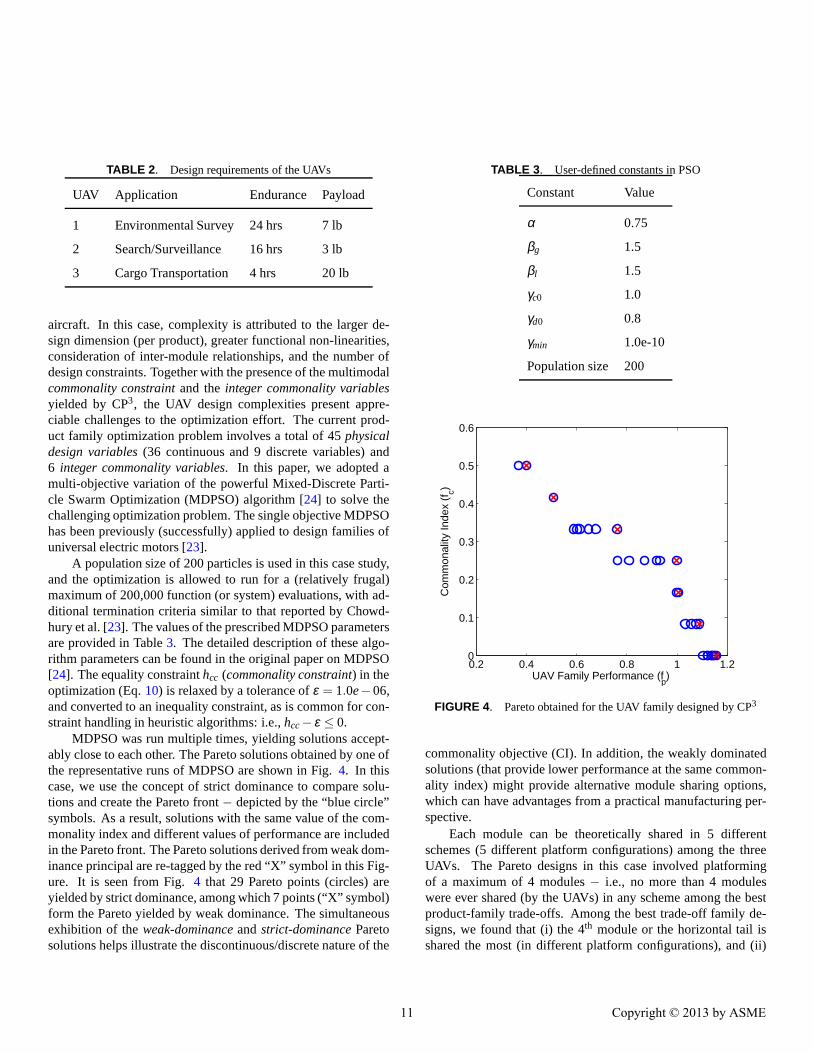
TABLE 2 . Design requirements of the UAVs
UAV Application Endurance Payload
1 Environmental Survey 24 hrs 7 lb
2 Search/Surveillance 16 hrs 3 lb
3 Cargo Transportation 4 hrs 20 lb
aircraft. In this case, complexity is attributed to the larger de-sign dimension (per product), greater functional non-linearities,consideration of inter-module relationships, and the number ofdesign constraints. Together with the presence of the multimodalcommonality constraintand theinteger commonality variablesyielded by CP3, the UAV design complexities present appre-ciable challenges to the optimization effort. The current prod-uct family optimization problem involves a total of 45physicaldesign variables(36 continuous and 9 discrete variables) and6 integer commonality variables. In this paper, we adopted amulti-objective variation of the powerful Mixed-Discrete Parti-cle Swarm Optimization (MDPSO) algorithm [24] to solve thechallenging optimization problem. The single objective MDPSOhas been previously (successfully) applied to design families ofuniversal electric motors [23].
A population size of 200 particles is used in this case study,and the optimization is allowed to run for a (relatively frugal)maximum of 200,000 function (or system) evaluations, with ad-ditional termination criteria similar to that reported by Chowd-hury et al. [23]. The values of the prescribed MDPSO parametersareprovided in Table3. The detailed description of these algo-rithm parameters can be found in the original paper on MDPSO[24]. The equality constrainthcc (commonality constraint) in theoptimization (Eq.10) is relaxed by a tolerance ofε = 1.0e−06,and converted to an inequality constraint, as is common for con-straint handling in heuristic algorithms: i.e.,hcc− ε ≤ 0.
MDPSO was run multiple times, yielding solutions accept-ably close to each other. The Pareto solutions obtained by one ofthe representative runs of MDPSO are shown in Fig.4. In thiscase, we use the concept of strict dominance to compare solu-tions and create the Pareto front− depicted by the “blue circle”symbols. As a result, solutions with the same value of the com-monality index and different values of performance are includedin the Pareto front. The Pareto solutions derived from weak dom-inance principal are re-tagged by the red “X” symbol in this Fig-ure. It is seen from Fig.4 that 29 Pareto points (circles) areyielded by strict dominance, among which 7 points (“X” symbol)form the Pareto yielded by weak dominance. The simultaneousexhibition of theweak-dominanceandstrict-dominanceParetosolutions helps illustrate the discontinuous/discrete nature of the
TABLE 3 . User-defined constants in PSO
Constant Value
α 0.75
βg 1.5
βl 1.5
γc0 1.0
γd0 0.8
γmin 1.0e-10
Population size 200
0.2 0.4 0.6 0.8 1 1.20
0.1
0.2
0.3
0.4
0.5
0.6
UAV Family Performance (fp)
Com
mon
ality
Inde
x (f
c)
FIGURE 4. Pareto obtained for the UAV family designed by CP3
commonality objective (CI). In addition, the weakly dominatedsolutions (that provide lower performance at the same common-ality index) might provide alternative module sharing options,which can have advantages from a practical manufacturing per-spective.
Each module can be theoretically shared in 5 differentschemes (5 different platform configurations) among the threeUAVs. The Pareto designs in this case involved platformingof a maximum of 4 modules− i.e., no more than 4 moduleswere ever shared (by the UAVs) in any scheme among the bestproduct-family trade-offs. Among the best trade-off family de-signs, we found that (i) the 4th module or the horizontal tail isshared the most (in different platform configurations), and (ii)
11 Copyright © 2013 by ASME
the 1st module or the wing is shared the least. The latter obser-vation is expected, since the aircraft aerodynamic performance ismost strongly influenced by the wing design; hence, the wing de-sign is most sensitive to the variations in the specified enduranceand payload.
The maximum commonality index obtained by optimizationis equal to 0.5 (leftmost Pareto points in Fig.4), which corre-sponds to a UAV family comprising 12 unique modules. Thismaximum commonality is accomplished at the cost of almosta two-thirds (66%) reduction in the average UAV performance(i.e. average UAV range/fuel-consumption). The maximum per-formance accomplished is 1.16MPGAS, which corresponds to anaverage range/fuel-consumption of 1566 miles/gallon for the 3UAVs. In the case of the maximum-performance design, thecommonality is zero, i.e., the UAV family is comprised of (themaximum possible) 18 unique modules. The individual UAVperformances given by the Pareto solutions with the maximumcommonality and the maximum performance are compared inTable4. In this table, “Max CI” represents the Pareto solutionwith the maximum commonality (among 3 UAVs), and “MaxPerf.” represents the Pareto solution with the maximum UAV-family performance (average range/fuel-consumption).
It is readily evident from Table4 that a significant com-promise in the individual UAVrange/fuel-consumptionis neces-sary to accomplish greater commonality among the UAVs. Thesecond UAV, with specified medium endurance and payload,experienced the maximum relative compromise inrange/fuel-consumption. On the other hand, the third UAV, with speci-fied low endurance and high payload, accomplished the lowestrange/fuel-consumptionin both cases (high CI and high perfor-mance cases). This observation shows that in general, high pay-loads are expected to result in lowrange/fuel-consumption. In-terestingly, although the endurance was specified to be 24, 16,and 4 hours respectively for the three UAVs, all of them endedup with relatively high endurance values of 29-36 hours for theoptimized family with maximum commonality.
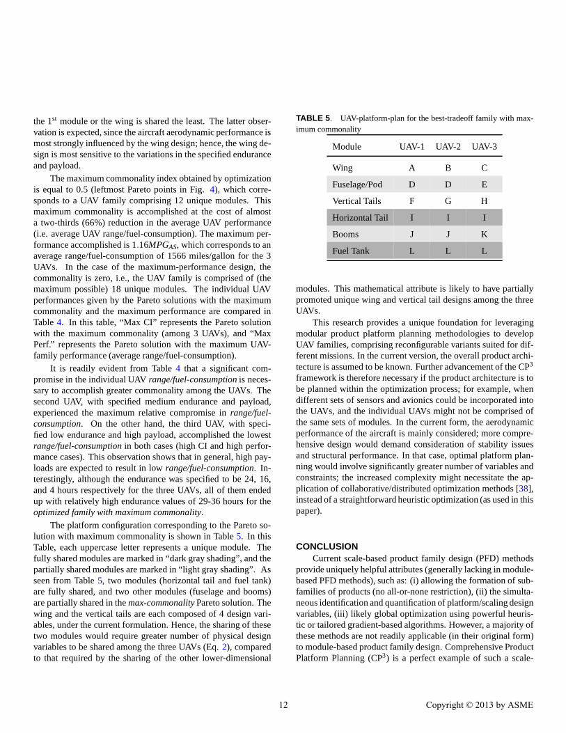
The platform configuration corresponding to the Pareto so-lution with maximum commonality is shown in Table5. In thisTable, each uppercase letter represents a unique module. Thefully shared modules are marked in “dark gray shading”, and thepartially shared modules are marked in “light gray shading”. Asseen from Table5, two modules (horizontal tail and fuel tank)are fully shared, and two other modules (fuselage and booms)are partially shared in themax-commonalityPareto solution. Thewing and the vertical tails are each composed of 4 design vari-ables, under the current formulation. Hence, the sharing of thesetwo modules would require greater number of physical designvariables to be shared among the three UAVs (Eq.2), comparedto that required by the sharing of the other lower-dimensional
TABLE 5 . UAV-platform-plan for the best-tradeoff family with max-imum commonality
Module UAV-1 UAV-2 UAV-3
Wing A B C
Fuselage/Pod D D E
Vertical Tails F G H
Horizontal Tail I I I
Booms J J K
Fuel Tank L L L
modules. This mathematical attribute is likely to have partiallypromoted unique wing and vertical tail designs among the threeUAVs.
This research provides a unique foundation for leveragingmodular product platform planning methodologies to developUAV families, comprising reconfigurable variants suited for dif-ferent missions. In the current version, the overall product archi-tecture is assumed to be known. Further advancement of the CP3
framework is therefore necessary if the product architecture is tobe planned within the optimization process; for example, whendifferent sets of sensors and avionics could be incorporated intothe UAVs, and the individual UAVs might not be comprised ofthe same sets of modules. In the current form, the aerodynamicperformance of the aircraft is mainly considered; more compre-hensive design would demand consideration of stability issuesand structural performance. In that case, optimal platform plan-ning would involve significantly greater number of variables andconstraints; the increased complexity might necessitate the ap-plication of collaborative/distributed optimization methods [38],instead of a straightforward heuristic optimization (as used in thispaper).
CONCLUSIONCurrent scale-based product family design (PFD) methods
provide uniquely helpful attributes (generally lacking in module-based PFD methods), such as: (i) allowing the formation of sub-families of products (no all-or-none restriction), (ii) the simulta-neous identification and quantification of platform/scaling designvariables, (iii) likely global optimization using powerful heuris-tic or tailored gradient-based algorithms. However, a majority ofthese methods are not readily applicable (in their original form)to module-based product family design. Comprehensive ProductPlatform Planning (CP3) is a perfect example of such a scale-
12 Copyright © 2013 by ASME

TABLE 4 . Comparing Pareto solutions with maximum commonality and maximum performance
Endurance (hrs) Payload (lbs) Range/Fuel (mpg)
UAV Max CI Max Perf. Max CI Max Perf. Max CI Max Perf.
1 36.0 24.0 7.0 7.0 553.5 1323.0
2 32.9 16.0 3.0 3.0 621.0 2470.5
3 29.4 4.0 20.0 20.0 445.5 904.5
based PFD method. In this paper, effective modifications ofthe commonality matrixand thecommonality constraintis per-formed to extend the applicability of CP3 to module-based PFD.In addition to thecommonality variablesthat regulate module-sharing between products, the newcommonality matrixdefini-tion presents module-inclusion variables that determine whethera module is included/excluded in a particular product variant. Inthe newcommonality constraint, the sharing of modules gener-ally entails the sharing of all physical-variables within the mod-ule. The newcommonality constrainthowever also allows mod-ule variables to get shared (or scale) individually if desired by thedesigner. These important modifications can also be leveraged inother popular scale-based PFD approaches, facilitating the trans-lation of their beneficial attributes to the quantitative design ofmodule-based product platforms.
The modified CP3 method is applied to design a familyof three Unmanned Aerial Vehicles (UAVs) with different en-durance and payload capacity specifications. These UAVs areintended for the following civilian applications: (i) environmen-tal survey, (ii) search/surveillance, and (iii) cargo transportation.Optimization of the UAV family is performed to maximize theaverage range/fuel-consumption while maximizing the common-ality among the three UAVs; to this end, a multi-objective varia-tion of the mixed-discrete PSO is implemented. The Pareto solu-tions obtained span from “a maximum commonality index of 0.5at a range/fuel-consumption of 541 miles/gallon” to “ a maximumrange/fuel-consumption of 1566 miles/gallon at no commonal-ity among the 3 UAVs”. We found that among the best tradeoffUAV-families, the horizontal tail is the most likely to be shared,whereas the wing is the least likely to be shared. Such a UAVfamily derived from common platforms is expected to providesignificant savings to the manufacturer, while enabling the man-ufacturer to effectively address different market segments. Fur-thermore, the development of such modular UAVs, with likelypre-flight reconfigurability, provides unique advantages such asmulti-mission capabilities at significantly reduced costs to thecustomer/user− which can be an important direction in pushingthe paradigm in civilian UAV applications. Such novelreconfig-
urability concepts can further benefit though the consideration oftheactual assembly options(and their fabrication implications)for the modules within the modular PFD process.
Future application of the modular CP3 method to de-sign more complex products, where modules can be in-cluded/excluded/substituted, will further establish the potentialof this approach for practical application.
ACKNOWLEDGEMENTThe information and the illustrations provided by RenAir
LLC regarding their UAV conceptual designs are gratefully ac-knowledged.
REFERENCES[1] Simpson, T. W., Siddique, Z., and Jiao, R. J., 2006.Product
Platform and Product Family Design : Methods and Appli-cations. Springer, New York.
[2] Simpson, T. W., Chen, W., Allen, J. K., and Mistree, F.,1996. “Conceptual design of a family of products throughthe use of the robust concept exploration method”. In6th AIAA/USAF/NASA/ISSMO Symposium on Multidis-ciplinary Analysis and Optimization, no. AIAA-96-4161-CP, AIAA, pp. 1535–1545.
[3] Simpson, T. W., 2004. “Product platform design and cus-tomization: Status and promise”.Artificial Intelligence forEngineering Design, Analysis and Manufacturing,18(1),pp. 3–20.
[4] Uzumeri, M., and Sanderson, S. W., 1995. “A frameworkfor model and product family competition”.Research Pol-icy, 24(4), July, pp. 583–607.
[5] Sanderson, S. W., and Uzumeri, M., 1997.Managing Prod-uct Families. IRWIN, USA.
[6] Sabbagh, K., 1996.Twenty-First Century Jet: The Makingand Marketing of Boeing 777. Scribner, USA.
[7] Simpson, T. W., 2006. Product Platform and Product
13 Copyright © 2013 by ASME

Family Design : Methods and Applications. Springer,New York, USA, ch. Methods for Optimizing Product Plat-forms and Product Families: Overview and Classification,pp. 133–156.
[8] Khire, R., and Messac, A., 2008. “Selection-integrated op-timization (sio) methodology for optimal design of adaptivesystems”.ASME Journal of Mechanical Design,130(10),October, pp. 101401:1–13.
[9] Khajavirad, A., Michalek, J. J., and Simpson, T. W., 2009.“An efficient decomposed multiobjective genetic algorithmfor solving the joint product platform selection and prod-uct family design problem with generalized commonal-ity”. Structural and Multidisciplinary Optimization,39(2),pp. 187–201.
[10] Chen, C., and Wang, L. A., 2008. “Modified geneticalgorithm for product family optimization with platformspecified by information theoretical approach”.Journal ofShanghai Jiaotong University (Science),13(3), pp. 304–311.
[11] Rai, R., and Allada, V., 2007. “Modular product familydesign: An agent based optimization technique”.Interna-tional Journal of Production Research,41(17), pp. 4075–4098.
[12] Fujita, K., and Yoshida, H., 2001. “Product vari-ety optimization: Simultaneous optimization of modulecombination and module attributes”. In ASME 2001International Design Engineering Technical Conferences(IDETC), no. DETC2001/DAC-21058, ASME.
[13] Fujita, K., and Yoshida, H., 2004. “Product variety op-timization simultaneously designing module combinationand module attributes”.Concurrent Engineering,12(2),pp. 105–118.
[14] Stone, R. B., Wood, K. L., and Crawford, R. H., 2000. “Aheuristic method to identify modules from a functional de-scription of a product”.Design Studies,21(1), pp. 5–31.
[15] Dahmus, J. B., Gonzalez-Zugasti, J. P., and Otto, K. N.,2001. “Modular product architecture”.Design Studies,22,pp. 409–424.
[16] Guo, F., and Gershenson, J. K., 2003. “Compari-son of modular measurement methods based on consis-tency analysis and sensitivity analysis”. In ASME 2003International Design Engineering Technical Conferences(IDETC), no. DETC2003/DTM-48634, ASME.
[17] Jose, A., and Tollenaere, M., 2005. “Modular and platformmethods for product family design: Literature analysis”.Journal of Intelligent Manufacturing,16, pp. 371–390.
[18] Kalligeros, K., de Weck, O., and de Neufville, R., 2006.“Platform identification using design structure matrices”.In Sixteenth Annual International Symposium of the Inter-
national Council On Systems Engineering (INCOSE), IN-COSE.
[19] Sharon, A., Dori, D., and de Weck, O., 2009. “Model-baseddesign structure matrix: Deriving a dsm from an object-process model”. In Second International Symposium onEngineering Systems, CESUN and MIT ESD.
[20] Yu, T. L., Yassine, A. A., and Goldberg, D. E., 2007. “Aninformation theoretic method for developing modular ar-chitectures using genetic algorithms”.Research in Engi-neering Design,18, pp. 91–109.
[21] Lewis, P., and Mattson, C., 2010. “Methodology forthe design of unmanned aircraft product families”. In6th AIAA MDO Specialists Conference, no. AIAA-2010-2836, AIAA.
[22] Chowdhury, S., Messac, A., and Khire, R., 2011. “Com-prehensive product platform planning (cp3) framework”.ASME Journal of Mechanical Design (Special Issue on De-signing Complex Engineered Systems),133(10), October,p. 101004.
[23] Chowdhury, S., Messac, A., and Khire, R., 2012. “Com-prehensive product platform planning (cp3) using mixeddiscrete particle swarm optimization and a new common-ality index”. In ASME 2012 International Design Engi-neering Technical Conferences (IDETC), no. DETC2012-70954, ASME.
[24] Chowdhury, S., Tong, W., Messac, A., and Zhang, J., 2013.“A mixed-discrete particle swarm optimization with ex-plicit diversity-preservation”. Structural and Multidisci-plinary Optimization,47(3), March, pp. 367–388.
[25] Khajavirad, A., and Michalek, J. J., 2008. “A decomposedgradient-based approach for generalized platform selectionand variant design in product family optimization”.ASMEJournal of Mechanical Design,130, July, pp. 071101:1–8.
[26] Willcox, K., and Wakayama, S., 2003. “Simultaneous opti-mization of a multiple-aircraft family”.Journal of Aircraft,40(4), pp. 616–622.
[27] Allison, J., Roth, B., Kokkolaras, M., Kroo, I., and Pa-palambros, P. Y., 2006. “Aircraft family design usingdecomposition-based methods”. In 11th AIAA/ISSMOMultidisciplinary Analysis and Optimization Conference,AIAA.
[28] Cabral, L. V., and Paglione, P., 2005. “Conceptual design offamilies of aircraft using multi objective design optimiza-tion theory and genetic algorithm techniques”. In 6th WorldCongresses of Structural and Multidisciplinary Optimiza-tion.
[29] Cabral, L. V., and Paglione, P., 2012. “Methodology forthe design of unmanned aircraft product families”. In 28thInternational Congress of the Aeronautical Sciences, ICAS.
14 Copyright © 2013 by ASME

[30] Pate, D. J., Patterson, M. D., and German, B. J., 2012.“Optimizing families of reconfigurable aircraft for multiplemissions”.L’Aerophile, 49(6), pp. 1988–2000.
[31] Martin, M., and Ishii, K., 1996. “Design for variety: amethodology for understanding the costs of product prolif-eration”. In ASME Design Engineering Technical Confer-ences and Computers in Engineering Conference, no. 96-DETC/DTM-1610, ASME.
[32] Cox, T. H., Nagy, C. J., Skoog, M. A., Somers, I. A., andWarner, R., 2005. A report overview of the civil uav capa-bility assessment. Tech. rep., NASA.
[33] RenAir, 2012. Unmanned Aerial Sysytem-based Wind Re-source Assessment Technology. www.renairtech.com.
[34] Breguet, L.“, 1921.”.L’Aerophile, 29(271).[35] Corke, T., 2002.Design of Aircraft, 1 ed. Prentice Hall.[36] Gundlach, J., 2011.Designing Unmanned Aircraft Sys-
tems: A Comprehensive Approach, 1 ed. American Instituteof Aeronautics & Astronautics.
[37] Barnard Microsystems Limited, 2012. Firstatlantic crossing by an unmanned aircraft.www.barnardmicrosystems.com.
[38] Kroo, I., 2004. Distributed multidisciplinary design andcollaborative optimization. VKI Lecture Series on Opti-mization Methods for Multicriteria/Multidisciplinary De-sign, November.
15 Copyright © 2013 by ASME