cp3 humidity
TRANSCRIPT
i
Chapter 3 Measurement of Humidity CONTENTS
3.1 Definitions and units ................................................................................................................................... 1
(1) Vapor pressure ..................................................................................................................................... 1
(2) Saturation vapor pressure .................................................................................................................... 1
(3) Dewpoint temperature ......................................................................................................................... 1
(4) Relative humidity ................................................................................................................................ 1
3.2 Hygrometers ................................................................................................................................................ 1
3.2.1 Psychrometer ............................................................................................................................................... 1
(1) Principle of measurement .................................................................................................................... 1
(2) Structure and composition ................................................................................................................... 1
(3) Psychrometric formula and psychrometric table ................................................................................. 2
(4) Calculations of vapor pressure, dewpoint temperature, and relative humidity .................................... 3
Calculation of vapor pressure ..................................................................................................................... 3
Determination of dewpoint temperature ..................................................................................................... 5
Calculation of relative humidity ................................................................................................................. 5
(5) Precautions for using the aspirated psychrometer ................................................................................ 6
(6) Sources to cause errors ........................................................................................................................ 7
(7) Maintenance ........................................................................................................................................ 7
Routine maintenance .................................................................................................................................. 7
Periodic maintenance .................................................................................................................................. 7
(8) Calibration ........................................................................................................................................... 8
(9) Repair .................................................................................................................................................. 8
(10) Transportation and installation ........................................................................................................... 8
3.2.2 Hair hygrometer ........................................................................................................................................... 9
(1) Principle of measurement and structure .............................................................................................. 9
(2) Precautions for using the hair hygrograph ......................................................................................... 10
(3) Sources to cause errors ...................................................................................................................... 10
(4) Maintenance ...................................................................................................................................... 11
Routine maintenance ................................................................................................................................ 11
Periodic maintenance ................................................................................................................................ 11
ii
(5) Calibration ......................................................................................................................................... 11
(6) Repair ................................................................................................................................................ 11
(7) Transportation and installation .......................................................................................................... 12
3.2.3 Electronic hygrometer (capacitive type) .................................................................................................... 13
(1) Structure and composition ................................................................................................................. 13
(2) Characteristics of the sensor .............................................................................................................. 14
(3) Sources to cause errors ...................................................................................................................... 14
(4) Maintenance ...................................................................................................................................... 14
Routine maintenance ................................................................................................................................ 14
Periodic maintenance ................................................................................................................................ 14
(5) Calibration ......................................................................................................................................... 15
(6) Repair ................................................................................................................................................ 15
(7) Transportation and installation .......................................................................................................... 15
3.2.4 Chilled-mirror dewpoint hygrometer ...................................................................................................... 15
(1) Structure and composition sensor(mirror) .................................................................................... 15
(2) Structure ........................................................................................................................................... 16
(3) Error factor ....................................................................................................................................... 16
(4) Maintenance ..................................................................................................................................... 16
(5) Calibration ........................................................................................................................................ 16
(6) Repair ............................................................................................................................................... 16
(7) Transportation and installation .......................................................................................................... 16
3.3 Example of calibration ................................................................................................................................. 17
(1) Measurement and calibration with chilled-mirror dewpoint hygrometer ......................................... 17
(2) Preparation ....................................................................................................................................... 17
(3) Measurement .................................................................................................................................... 18
1
Chapter 3 Measurement of Humidity
3.1 Definitions and units
(1) Vapor pressure
Vapor pressure is the partial pressure of water vapor in the air, expressed in hPa.
(2) Saturation vapor pressure
Saturation vapor pressure is the vapor pressure that is in a thermodynamic equilibrium with the surface of
water or ice, expressed in hPa.
(3) Dewpoint temperature
Dewpoint temperature is the air temperature at which the moist air saturates respect to water at a given
pressure.
The dewpoint temperature is usually equal to or lower than the actual air temperature. The temperature at
which moist air saturates with respect to ice is called the frost point temperature. the unit of these
temperatures is ℃.
(4) Relative humidity
As shown below, relative humidity (H) is the ratio of the vapor pressure (e) of the moist air to its saturation
vapor pressure (es) at its temperature, which is expressed in %.
H = (e/es) × 100 %
H = (e/esw) × 100 %
H = (e/esi) × 100 %
where Hw and esw are the saturation vapor pressure with respect to water, and Hi and esi are the saturation
vapor pressure with respect to ice, respectively.
3.2 Hygrometers
3.2.1 Psychrometer
(1) Principle of measurement
When water or ice covers the bulb of a thermometer (wet-bulb), latent heat is removed from the surface of the
bulb as the water evaporates, and the wet-bulb temperature becomes lower than the air (dry-bulb) temperature.
At a lower humidity, water evaporates more actively, so that the wet-bulb temperature lowerssharply. The
aspirated psychrometer measures humidity by measuring the difference between the dry-bulb temperature
and wet-bulb temperature.
(2) Structure and composition
The psychrometer consists of two thermometers of the same specifications, which are suspended side by side
in the air. One of them measures the actual air (dry-bulb) temperature while the other, whose bulb is covered
with a wet-bulb temperature.
2
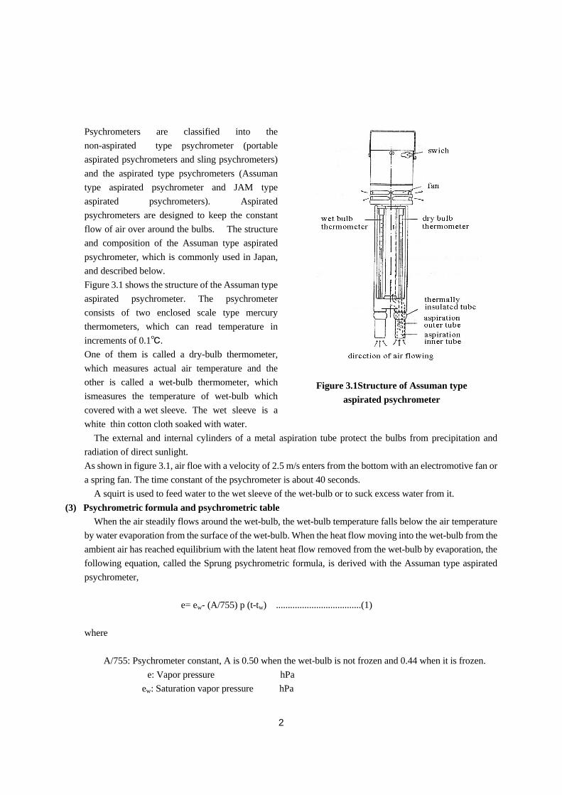
Psychrometers are classified into the
non-aspirated type psychrometer (portable
aspirated psychrometers and sling psychrometers)
and the aspirated type psychrometers (Assuman
type aspirated psychrometer and JAM type
aspirated psychrometers). Aspirated
psychrometers are designed to keep the constant
flow of air over around the bulbs. The structure
and composition of the Assuman type aspirated
psychrometer, which is commonly used in Japan,
and described below.
Figure 3.1 shows the structure of the Assuman type
aspirated psychrometer. The psychrometer
consists of two enclosed scale type mercury
thermometers, which can read temperature in
increments of 0.1℃.
One of them is called a dry-bulb thermometer,
which measures actual air temperature and the
other is called a wet-bulb thermometer, which
ismeasures the temperature of wet-bulb which
covered with a wet sleeve. The wet sleeve is a
white thin cotton cloth soaked with water.
The external and internal cylinders of a metal aspiration tube protect the bulbs from precipitation and
radiation of direct sunlight.
As shown in figure 3.1, air floe with a velocity of 2.5 m/s enters from the bottom with an electromotive fan or
a spring fan. The time constant of the psychrometer is about 40 seconds.
A squirt is used to feed water to the wet sleeve of the wet-bulb or to suck excess water from it.
(3) Psychrometric formula and psychrometric table
When the air steadily flows around the wet-bulb, the wet-bulb temperature falls below the air temperature
by water evaporation from the surface of the wet-bulb. When the heat flow moving into the wet-bulb from the
ambient air has reached equilibrium with the latent heat flow removed from the wet-bulb by evaporation, the
following equation, called the Sprung psychrometric formula, is derived with the Assuman type aspirated
psychrometer,
e= ew- (A/755) p (t-tw) ....................................(1)
where
A/755: Psychrometer constant, A is 0.50 when the wet-bulb is not frozen and 0.44 when it is frozen.
E , e: Vapor pressure hPa
ew: Saturation vapor pressure ,hPa
Figure 3.1Structure of Assuman type
aspirated psychrometer
3
,,p: Atmospheric pressure hPa
, , ,,,t: Dry-bulb temperature ℃
,, ,tw: Wet-bulb temperature ℃
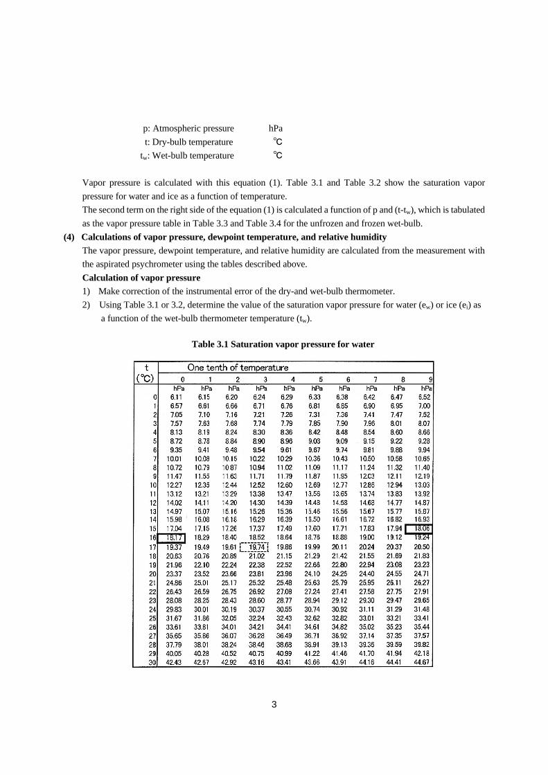
Vapor pressure is calculated with this equation (1). Table 3.1 and Table 3.2 show the saturation vapor
pressure for water and ice as a function of temperature.
The second term on the right side of the equation (1) is calculated a function of p and (t-tw), which is tabulated
as the vapor pressure table in Table 3.3 and Table 3.4 for the unfrozen and frozen wet-bulb.
(4) Calculations of vapor pressure, dewpoint temperature, and relative humidity
The vapor pressure, dewpoint temperature, and relative humidity are calculated from the measurement with
the aspirated psychrometer using the tables described above.
Calculation of vapor pressure
1) Make correction of the instrumental error of the dry-and wet-bulb thermometer.
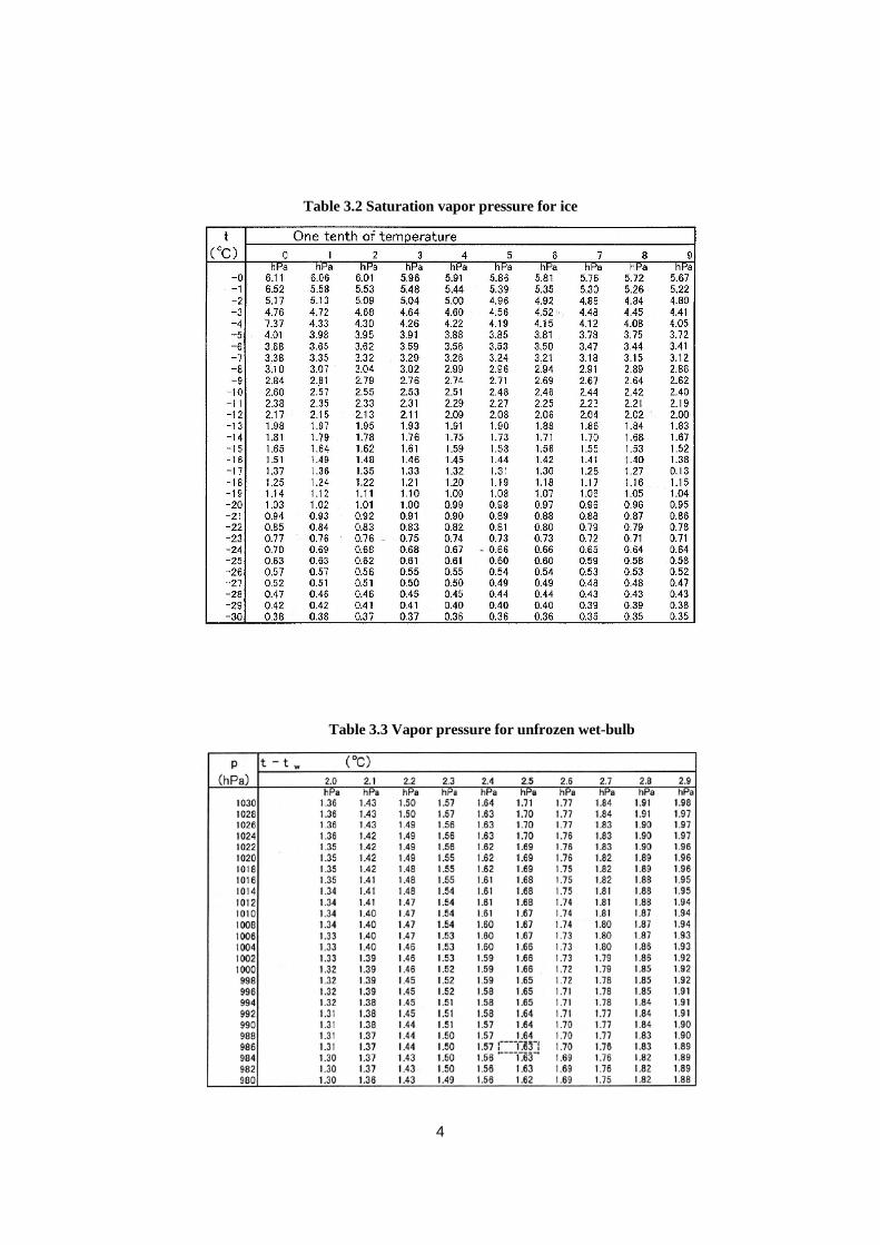
2) Using Table 3.1 or 3.2, determine the value of the saturation vapor pressure for water (ew) or ice (ei) as
a function of the wet-bulb thermometer temperature (tw).
Table 3.1 Saturation vapor pressure for water
4
Table 3.2 Saturation vapor pressure for ice
Table 3.3 Vapor pressure for unfrozen wet-bulb
5
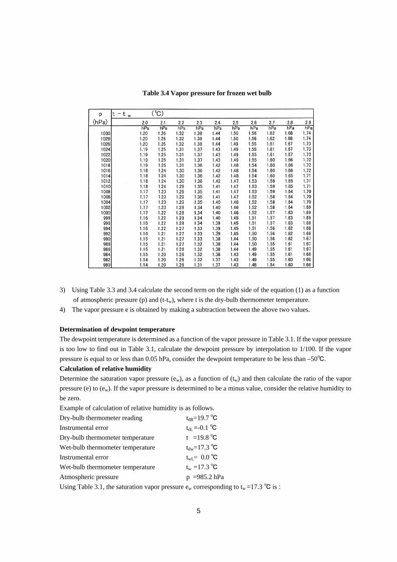
3) Using Table 3.3 and 3.4 calculate the second term on the right side of the equation (1) as a function
of atmospheric pressure (p) and (t-tw), where t is the dry-bulb thermometer temperature.
4) The vapor pressure e is obtained by making a subtraction between the above two values.
Determination of dewpoint temperature
The dewpoint temperature is determined as a function of the vapor pressure in Table 3.1. If the vapor pressure
is too low to find out in Table 3.1, calculate the dewpoint pressure by interpolation to 1/100. If the vapor
pressure is equal to or less than 0.05 hPa, consider the dewpoint temperature to be less than –50℃.
Calculation of relative humidity
Determine the saturation vapor pressure (ew), as a function of (tw) and then calculate the ratio of the vapor
pressure (e) to (ew). If the vapor pressure is determined to be a minus value, consider the relative humidity to
be zero.
Example of calculation of relative humidity is as follows.
Dry-bulb thermometer reading tdR=19.7 ℃
Instrumental error tdl,,=-0.1 ℃
Dry-bulb thermometer temperature t,,,=19.8 ℃
Wet-bulb thermometer temperature tdw=17.3 ℃
Instrumental error twl,= 0.0 ℃
Wet-bulb thermometer temperature tw,,=17.3 ℃
Atmospheric pressure p =985.2 hPa
Using Table 3.1, the saturation vapor pressure ew corresponding to tw =17.3 ℃ is :
Table 3.4 Vapor pressure for frozen wet bulb
6
ew=19.74 hPa
Using Table 3.3, the second term on the right side of the equation (1), (Ap (t- tw)/755) is calculated using
the value of (t- tw)=2.5℃ and p=985.2 hPa
Ap (t- tw)/755=1.63 hPa,
where A=0.50 is used.
Thus the vapor pressure e is calculated using the equation (1),
e=19.74-1.63
e=18.11 hPa.
Using Table 3.1, the dewpoint temperature td is determined to be
td=15.9℃.
Using again Table 3.1, the saturation vapor pressure ew corresponding to the air temperature t =19.8 ℃ is :
ew=23.08 hPa
Thus the relative humidity is calculate as follows:
H= (e/ew)×100
=(18.11/23.08)×100
=78%.
(5) Precautions for using the aspirated psychrometer
1) Supply water to the wet-bulb with distilled water or soft water, using the squirt.
If the air temperature is 0℃ or less, the water of the wet-sleeve may be frozen. In that case, make the icy
membrane around the wet-bulb as thin as possible, using warmed water.
<Notes>
a) Do not supply the wet-bulb with too much water. If too much water is supplied to the bulb suck
excess water by squirt or by attaching a brush to the bottom of the bulb. Do not wet the inside of
the aspiration tube.
b) Use water of the air temperature.
c) In the case that the air temperature is high and the humidity is low, the wet-bulb may dry up by the
time when the observer reads the temperature. In such a case, supply water to the wet-bulb
repeatedly.
2) Operate the fan for aspiration to make the air flow around the bulbs
3) Before reading a wet-bulb temperature, it is necessary that the indication is stable.
When the wet-bulb temperature is slightly below 0℃, the water of the wet-sleeve may not freeze but be
super cooled. Thus when the temperature is around or less than 0℃, see carefully the state of the
wet-bulb to find whether the wet-bulb is frozen or super cooled and use the appropriate saturation vapor
pressure table. To determine whether the wet-bulb is frozen or super cooled, gently touch the surface of
the wet-bulb with something like a needle. Degree of gloss on the surface of the wet-bulb is also useful
to check if the wet-bulb is frozen.
<Notes>
a) The time for aspiration required to stabilize the reading is typically five minutes if the temperature is
0℃ or higher. If the temperature is less than 0℃, an aspiration time longer than five minutes will be
needed.
7
b) If then evaporation from the wet-bulb is a little because of high humidity or if the wet-bulb
temperature is slightly below 0℃, it would take 10 to 20 minutes for the stabilization of reading.
c) If the wet-bulb temperature is much lower than 0℃, make calculations using the saturation vapor
pressure for ice.
4) Read the dry-bulb temperature.
5) Read the wet-bulb temperature.
6) Read the dry-bulb temperature and wet-bulb temperature again.
<Notes>
a) In the foggy condition, the wet-bulb temperature may be higher than the dry-bulb temperature. In
such a case, consider the dry-bulb temperature to be the wet-bulb temperature.
b) If the first reading and the second one are different, repeat the reading again.
(6) Sources to cause errors
a) The psychrometer constant A in the psychrometric formula varies, depending on whether the
wet-bulb is frozen or not and the incorrect determination of the wet-bulb leads to errors. So the state
of the wet-bulb should be checked especially in cold conditions before the calculation.
b) As the temperature becomes lower, air contains less vapor, and the saturation pressure becomes
lower. So the wet-bulb temperature reading error affects the vapor pressure calculations more
significantly. Because of this, much care is needed with reading the psychrometer at low
temperatures.
c) A portable aspirated psychrometer which is not subjected to forced aspiration is significantly
affected by the natural wind. When a portable aspirated psychrometer is used in a thermometer
shelter and the natural wind speed ranges from 0.3 to 4.0 m/s, the error in humidity may become as
high as 7% because the aspiration velocity in the shelter is lower than the wind speed out of the
shelter.
d) The wet-bulb temperature is affected by oil on the wet sleeve as well as by any impurities, such as
salt dissolved in the water. A dirty wet sleeve also prevents correct measurement. Deposits of dirt
on the wet-bulb after the prolonged use may cause errors.
e) Generally, the dry-bulb and wet-bulb thermometers have the same size and shape. Because the
wet-bulb has higher thermal conductivity, it responds to changes in air temperature a little more
quickly than the dry-bulb. Normally, when the air temperature changes, the wet-bulb firstly
responds, causing a temporary change of humidity indication. On the other hand, the wet-bulb
responds less quickly when a thick icy membrane is formed on the bulb.
(7) Maintenance
Routine maintenance
Make sure the aspiration fan in running properly at every observation.
Periodic maintenance
a) If the wet sleeve becomes dirty, replace it with a new one. In Japan, the sleeve is replaced twice a
month. However, the sleeve must be replaced more frequently if it is placed in the environment
with much dirt or in the sea breeze zone.
b) Wash off deposits on the wet-bulb when the wet sleeve is replaced.
8
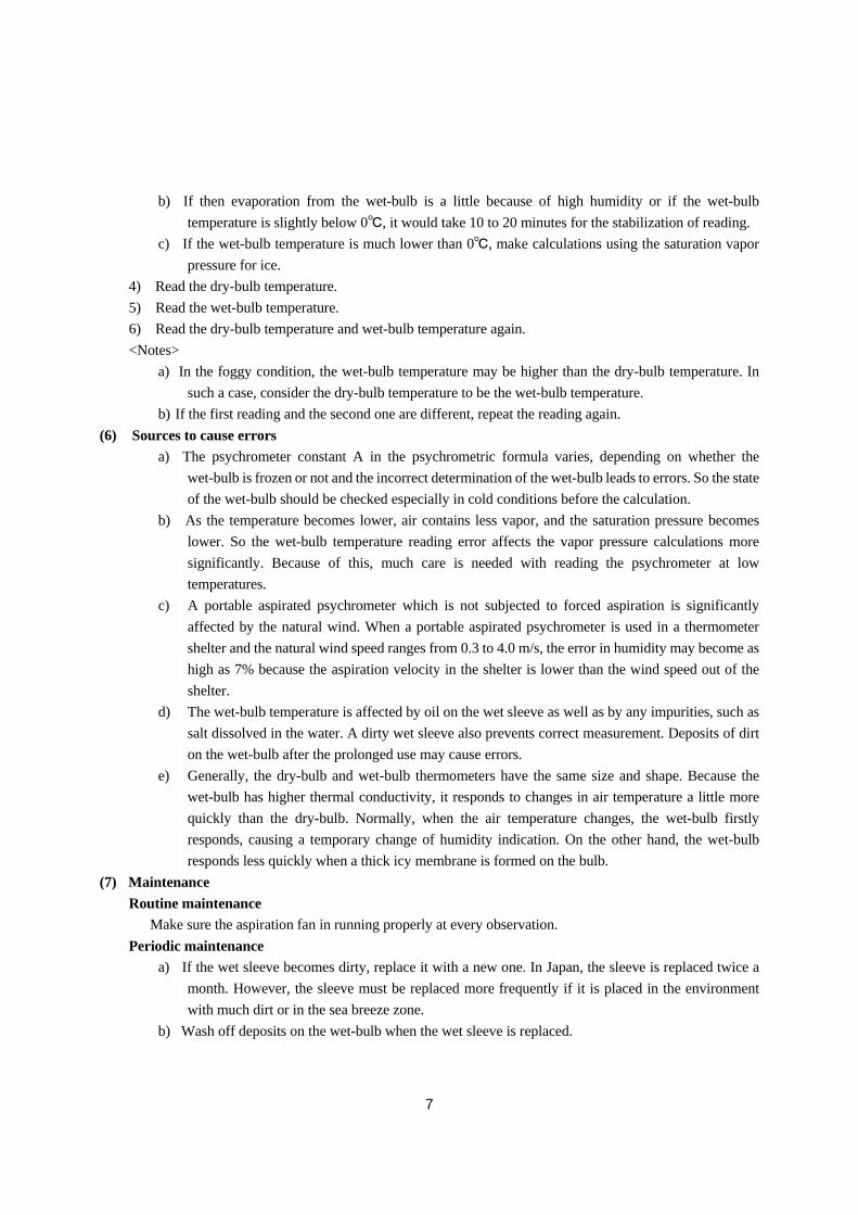
(8) Calibration
The psychrometer is calibrated by measuring
temperature, because it consists of thermometers. The
aspiration velocity of the aspirated psychrometer is
measured by the static pressure method as illustrated in
Figure 3.2. At first, a hole is made in the aspiration tube
where a thermometer bulb is placed. Next, the hole is
connected to a manometer using a probe like a Pitot tube
or a vinyl tube. Then air is led to flow through the
aspiration tube, and the differential pressure is measured
using the manometer to find the wind velocity. The
relationship between the manometer differential
pressure and the wind velocity is determined in a wind
tunnel in advance.
(9) Repair
A broken glass thermometer must be replaced since it
cannot be repaired. Refer to the instruction manual of the aspirator to repair the aspirator motor.
(10) Transportation and installation
Transportation [See 1.5(3), “Transportation of instruments”]
a) Wrap the glass parts of the psychrometer in a soft cloth, and wrap the entire psychrometer in
wrapping paper.
b) Place the psychrometer in a solid box and indicate “HANDLE WITH CARE” on the box.
Installation [See 1.5(4), “Siting and Exposure”]
a) Install the psychrometer in a wet-ventilated location protected from direct sunlight. Keep the
psychrometer away from sources of heat radiation, such as a concrete wall exposed to direct
sunlight.
b) Do no place the psychrometer near heat sources and vapor sources.
c) Place the bulbs about 1.2 to 2 ,m above the ground.
d) Suspend the psychrometer from a hanger on the supporting pole. Take readings of the
psychrometer in its suspended position or in the position that the aspiration entrance is inclined
windward.
e) place a non-aspirated type psychrometer in a thermometer shelter to protect it from precipitation,
direct sunlight and radiation.
Figure 3.2 Measurement of static pressure
9
3.2.2 Hair hygrometer
(1) Principle of measurement and structure
The hair hygrometer uses the characteristic of the hair that its length expands or shrinks response to the
relative humidity. the dimensions of various organic materials vary with their moisture content. A humidity
change takes an effect on the moisture content in such materials. The length of human hair from which liquid
are removed increases by 2 to 2.5% when relative humidity changes by 0 to 100%. Different types of human
hair show different changes in length. However, there is still a relationship between the length of hair and
relative humidity.
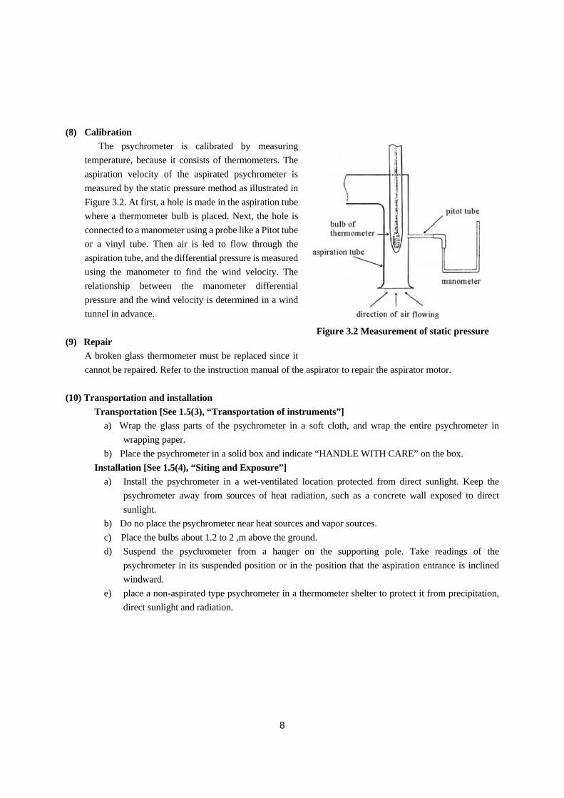
The hair hygrograph is a hair hygrometer to which a clock-driven drum is installed to record humidity no a
recording chart.
When the humidity in the air changes, a hair bundle ⑪ expands or shrinks, so hair joint metal attached to a
lever ⑩ moves, making a rotation of a main can ③. The weight of a pen arm attached to the shaft ⑥ give a
downward moment to the sub cam ④ .
Figure 3.3 Structure of hair hygrograph
①Indicator adjusting screw ②Weight ③Main cam
④Sub cam ⑤Rotation axis for main cam ⑥Rotation axis for sub cam
⑦Plate attaching sensor part of humidity , ⑧Screw attaching sub cam ⑨Connecting spring
⑩lever ⑪Hair bundle
10
The plumb ② of the main cam balances with moment
and a small change of the hair bundle ⑪ is magnified to the movement of the pen.
Since the length of the hair increases almost logarithmically with the increase of humidity, changes in
humidity are not indicated correctly when the elongation of hair is linearly recorded. The hair hygrometer
uses two special cams to put graduations on the hygrometer at equal intervals. A spring ⑨ joints cams ③ and
④ to prevent them from each other. The movement of the main cam ③ differ from that of the sub cam ④
depending on the position of the contact point of these two cams. At low humidity, the movement of the sub
cam ④ is less than that of the main cam ③. As humidity increases, the movement of the sub cam ④
increases.
The hair hygrometer is designed so that the two special cams cause the movement of the pen arm to be
proportional to the change in humidity. The hair hygrometer uses a recording chart with a humidity scale
divided into 100 equal segments. Each segment corresponds to 1%. So, humidity can be directly read from
the recording chart.
(2) Precautions for using the hair hygrograph
1) Before taking a reading of the hair hygrograph, gently tap the hygrometer to remove any mechanical
tension added to the hair bundle.
2) At every measurement with the hair hygrograph, the reading should be compared with the humidity
measured with the aspirated psychrometer at the same time. The difference of the humidity between
them is used as a correction value.
3) Time marks as well as the degree of clock accuracy should be recorded on the chart.
<Notes>
a) When making a time mark on the recording chart by moving the pen, take care to move the pen arm
downward. Moving the pen arm in the pen arm in the opposite direction(upward)makes the hair
bundle to expand, causing the hygrograph to become defective.
b) To determine the humidity from the recording chart, read the indication on the record then correct it
with correction values obtained by the procedure above.
(3) Sources to cause errors
a) Hair expands or shrinks due to changes in temperature as well as those in humidity. The expansion
or shrinkage of a hair corresponding to a temperature change of 1℃ is about 1/15 of the expansion
or shrinkage of a hair corresponding to a temperature change of 1% in usual air temperatures. Thus
no special temperature compensation is made in hair hygrograph. However, if the temperature
varies considerably, slight errors will occur. Because the hygroscopicity of hair begins to decrease
at around -15℃ and becomes almost nil at -40℃, the hair hygrometer does not serve at extremely
low air temperatures.
b) The response of hair to humidity has hysteresis. The hair length changes more when humidity
increases than when it decreases. The change of hair length observed when humidity increases is up
to 5 to 6% larger than that observed when humidity decreases.
11
c) The response time of the hair hygrometer depends on air temperature. The time constant of the hair
hygrometer, is about 10 seconds at 20℃ and about 30 seconds at -30℃.
d) After the hair hygrometer is exposed in low temperature and low humidity for a long time , reading
error increase due to the increasing of delay. This state could not be recovered until the hair is
saturated.
e) Hair is highly sensitive to contamination such as dust, ammonia, oil which adheres to hair when a
finger directly touches it, and exhaust gas.
f) Moving the pen arm to her direction the hair is tensioned makes the hair
elongate and causes a malfunction of the hair hygrometer.
g) If a hair hygrometer is left in the low humidity condition for a long time,
its reading changes causing large errors.
h) If the difference in reading between a hair hygrometer and an aspirated psychrometer is 5% or more
on average over 10 days, the hair hygrometer should be considered faulty.
(4) Maintenance
Routine maintenance
a) Clean the dusty hair bundle with dust or smoke with a soft brush.
b) If the hair bundle is extremely dirty or it has been used for several months, clean it with a painting
brush soaked with distilled warm water by gently touching the bundle.
c) Do not touch the hair bundle directly. Each of the parts of the hair hygrometer operates under slight
forces. When cleaning the parts, be sure to treat them gently
Periodic maintenance
a) Clean the hair bundle with a feather brush, wash it with a painting brush.
b) Make offset adjustments by comparing the reading of the hair hygrometer
with that of the aspirated psychrometer.
(5) Calibration
A hair hygrograph is calibrated by comparison with a working standard hygrometer in a humidity
generator chamber. Keep in mind that the response times of the hair hygrograph and the working standard
hygrometer are different. It is necessary that the temperature and humidity are kept constant in the chamber
during the comparison. The aspirated psychrometer is the simplest and the most correct working standard
hygrometer.
Even if no humidity generator is available, it is possible to make calibration by wetting the hair bundle with
water to reach the humidity of 100%. Note that if a hair bundle is soaked with too much water, offset
adjustments cannot be made correctly. The humidity in the room will be measured for calibration of the
lower humidity condition. The difference between a hair hygrograph and a working standard hygrometer is
analyzed from three or more data. The long-term stability and checked by comparisons for a prolonged
period.
(6) Repair
a) The pivots and pillows have been heat treated. If these parts are corroded, they should be ground
with an oil grind stone ensuring that they are not eccentric.
b) If ink is deposited on the pen, remove the pen from the pen arm, wipe off the ink, and clean the pen
12
in alcohol.
c) If a ink channel is clogged and ink does not flow regularly, insert a piece of thin paper through the
slit liquid.
d) If the contact points of the cams becomes dirty, polish it with a cloth moistened
with metal polish liquid.
e) Do not touch the lever because adjusting the lever of the hair hygrometer causes the change in its
magnification. Clean the other parts regularly.
(7) Transportation and installation
Transportation [See 1.5(3),”Transportation of instruments”
a) Tie the pen arm to the pen tip retainer loosely.
b) Tie the plumb attached to the main cam to the hinge of the pen arm.
c) Attach cardboard or a plate to the glass parts.
d) Insert paper between the central axis and the nuts pressing the clock-driver drum to eliminate the
backlashes above and below the clock-driver drum.
e) Wrap the humidity sensor unit in wrapping paper.
f) Records of all calibration results should be put into the instrument.
g) Attach a label indicating the type of the instrument and the name of the
observation site.
h) Wrap the whole instrument in wrapping paper. Place the instrument in a robust
box with legs so that the instruments cannot be set incorrectly. Place packing around the instrument
to avoid vibrations. Put the indication of “This Side Up” and “Handle with Care” on the box.
Installation[See 1.5 (4),”Siting and Exposure”]
a) The hair hygrometer should be installed in an thermometer shelter.
b) Do not install a hair hygrometer near animal sheds or factories using ammonia. As ammonia
damages the hair.
c) In cold areas, set a well-ventilated cover over the hair hygrometer to protect it from snow or ice
during sever conditions such as snowstorms.
d) Leave a hair hygrometer which has not been used for prolonged periods in an thermometer shelter
for two or three days before the beginning of its use.
13
3.2.3 Electronic hygrometer (capacitive type)
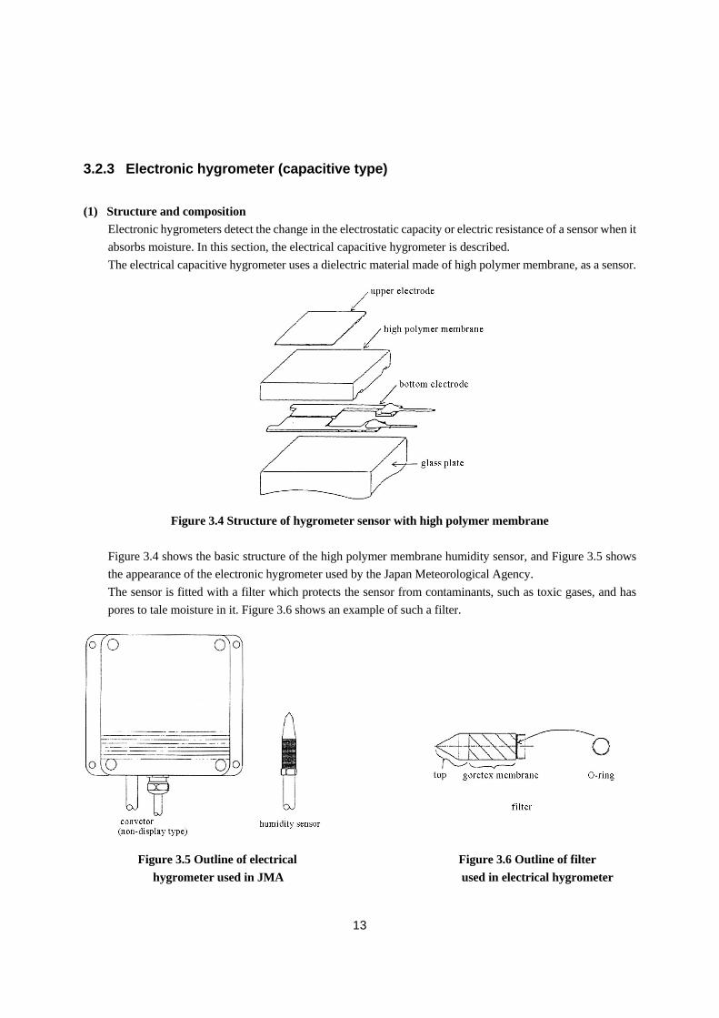
(1) Structure and composition
Electronic hygrometers detect the change in the electrostatic capacity or electric resistance of a sensor when it
absorbs moisture. In this section, the electrical capacitive hygrometer is described.
The electrical capacitive hygrometer uses a dielectric material made of high polymer membrane, as a sensor.
Figure 3.4 Structure of hygrometer sensor with high polymer membrane
Figure 3.4 shows the basic structure of the high polymer membrane humidity sensor, and Figure 3.5 shows
the appearance of the electronic hygrometer used by the Japan Meteorological Agency.
The sensor is fitted with a filter which protects the sensor from contaminants, such as toxic gases, and has
pores to tale moisture in it. Figure 3.6 shows an example of such a filter.
Figure 3.5 Outline of electrical Figure 3.6 Outline of filter
hygrometer used in JMA used in electrical hygrometer
14
(2) Characteristics of the sensor
The measurement range of the electrical capacitive hygrometer is from 0 to 100%, and its accuracy can be
improved by calibration. By calibrating with the standard hygrometer, the electrical capacitive hygrometer
attains the error of 1% or less in the range from 0 to 90% and error of 2% or less in the range from 90 to 100%.
The hysteresis becomes large when the humidity changes from high to low. It is within 1% at relative
humidity of 60-80%.
when relative humidity increases from 0 to 90% and the sensor absorbs moisture, the time constant of the
sensor is about six seconds. On the other hand, when relative humidity decreases from 90 to 0% and the
sensor releases moisture, the time constant is about 10 seconds.
For meteorological purposes, the sensor is put in a ventilation shelter to protect the sensor from
precipitation and sunlight with the aspiration speed of 2 to 4 m/s around the sensor. The time constant with
the shelter from the saturation to the room humidity is about 20 minutes, which is longer than that without the
shelter, because of the shelter’s large thermal capacity.
A high polymer membrane humidity sensor has temperature dependence of about 0.1%/℃ for the
temperature range from 5 to 30℃ and 0.2%/℃ for the temperature range from –30 to 0℃. Therefore, a
temperature sensor is installed together with the humidity sensor to compensate its temperature dependency.
(3) Sources to cause errors
a) Any difference between the ambient temperature and the sensor temperature causes an error. For
example, at 20℃ and 50%RH, a difference of 1℃ between the ambient temperature and the sensor
temperature results in an error of about 3%. At 90%RH, the error becomes up to about 6%. When
the sensor temperature is lower than the ambient temperature in a low humidity condition, dew may
form on the surface of the sensor. This will make a large measurement error. The sensor is housed
in an ventilation shelter to reduce or eliminate the difference of temperature between the sensor and
the ambient air to prevent dew formation.
b) The electronic capacitive hygrometer can be used in any environment where the human can live.
However, do not use the hygrometer in the atmosphere containing oil mist, flammable gas, dust,
organic solvents, acid, alkaline or ammonia. Using the hygrometer in the atmosphere may cause its
sensor electrodes to corrode, thus the sensor life is shortened. To prevent the sensor electrode from
corrosion, a protection filter is used to keep out dust or organic solvents.
(4) Maintenance
Routine maintenance
Routine maintenance is not needed.
Periodic maintenance
a) Compare the electrical capacitive hygrometer with the aspirated psychrometer once three months to
observe time-dependent changes.
b) Replace the protection filter with a new one twice a year. In rural areas where little soot is found ,
the interval between replacements may prolonged to a maximum of once a year.
15
(5) Calibration
If a humidity generator chamber is available, an electrical capacitive hygrometer is calibrated in the same
way as the hair hygrometer.
The sensor of the electrical hygrometer can be separated from display and recording units. This enables the
calibration in a small humidity generator chamber, in which it is easy to attain various humidity. Use
aspirated phychrometer or chilled-mirror dewpoint hygrometer as standard instrument.
(6) Repair
Because most of parts of the humidity sensor cannot be repaired, they must be replaced with new ones if they
become defective. Refer to the instruction manual of the hygrometer on the method to identify defects and to
replace parts.
(7) Transportation and installation
[See 1.5(3), “Transportation of instruments” and 1.5(4), “Siting and Exposure”]
Ask the manufacturer of the hygrometer for information about transportation, because precautions for
transportation differ by the type of the hygrometer.
The method of installation of the hygrometer sensor is basically the same as that of the aspirated
psychrometer.
3.2.4 Chilled-mirror dewpoint hygrometer
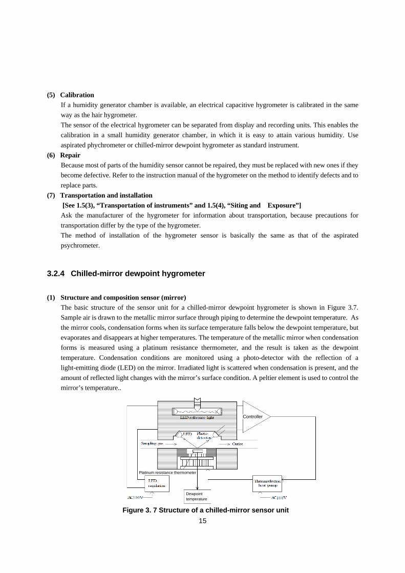
(1) Structure and composition sensor (mirror)
The basic structure of the sensor unit for a chilled-mirror dewpoint hygrometer is shown in Figure 3.7.
Sample air is drawn to the metallic mirror surface through piping to determine the dewpoint temperature. As
the mirror cools, condensation forms when its surface temperature falls below the dewpoint temperature, but
evaporates and disappears at higher temperatures. The temperature of the metallic mirror when condensation
forms is measured using a platinum resistance thermometer, and the result is taken as the dewpoint
temperature. Condensation conditions are monitored using a photo-detector with the reflection of a
light-emitting diode (LED) on the mirror. Irradiated light is scattered when condensation is present, and the
amount of reflected light changes with the mirror’s surface condition. A peltier element is used to control the
mirror’s temperature..
Figure 3. 7 Structure of a chilled-mirror sensor unit
Controller
Platinum resistance thermometer
Dewpoint temperature
16
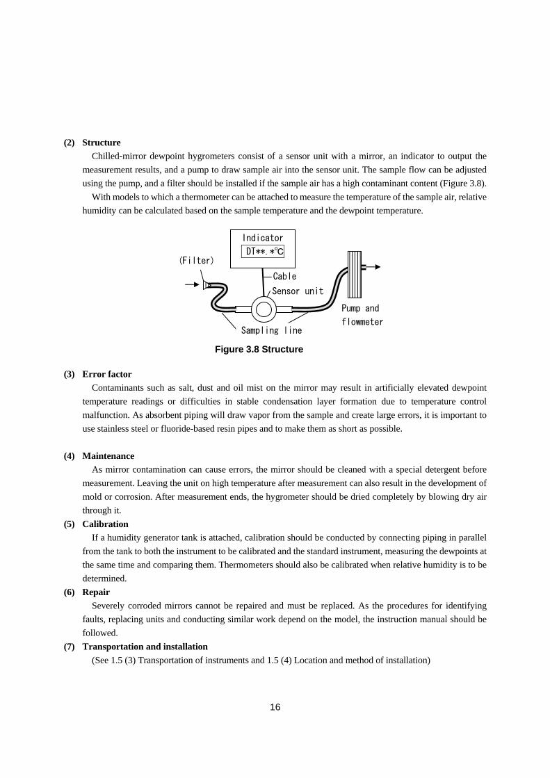
(2) Structure
Chilled-mirror dewpoint hygrometers consist of a sensor unit with a mirror, an indicator to output the
measurement results, and a pump to draw sample air into the sensor unit. The sample flow can be adjusted
using the pump, and a filter should be installed if the sample air has a high contaminant content (Figure 3.8).
With models to which a thermometer can be attached to measure the temperature of the sample air, relative
humidity can be calculated based on the sample temperature and the dewpoint temperature.
(3) Error factor
Contaminants such as salt, dust and oil mist on the mirror may result in artificially elevated dewpoint
temperature readings or difficulties in stable condensation layer formation due to temperature control
malfunction. As absorbent piping will draw vapor from the sample and create large errors, it is important to
use stainless steel or fluoride-based resin pipes and to make them as short as possible.
(4) Maintenance
As mirror contamination can cause errors, the mirror should be cleaned with a special detergent before
measurement. Leaving the unit on high temperature after measurement can also result in the development of
mold or corrosion. After measurement ends, the hygrometer should be dried completely by blowing dry air
through it.
(5) Calibration
If a humidity generator tank is attached, calibration should be conducted by connecting piping in parallel
from the tank to both the instrument to be calibrated and the standard instrument, measuring the dewpoints at
the same time and comparing them. Thermometers should also be calibrated when relative humidity is to be
determined.
(6) Repair
Severely corroded mirrors cannot be repaired and must be replaced. As the procedures for identifying
faults, replacing units and conducting similar work depend on the model, the instruction manual should be
followed.
(7) Transportation and installation
(See 1.5 (3) Transportation of instruments and 1.5 (4) Location and method of installation)
Figure 3.8 Structure
Sensor unit
Indicator
DT**.*℃
Sampling line
Cable
(Filter)
Pump and
flowmeter
17
.3.3 Example of calibration
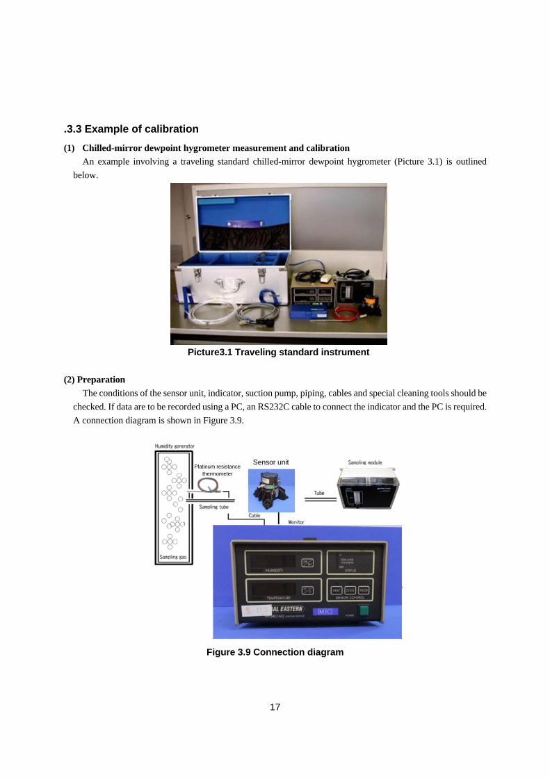
(1) Chilled-mirror dewpoint hygrometer measurement and calibration
An example involving a traveling standard chilled-mirror dewpoint hygrometer (Picture 3.1) is outlined
below.
(2) Preparation
The conditions of the sensor unit, indicator, suction pump, piping, cables and special cleaning tools should be
checked. If data are to be recorded using a PC, an RS232C cable to connect the indicator and the PC is required.
A connection diagram is shown in Figure 3.9.
Picture3.1 Traveling standard instrument
Figure 3.9 Connection diagram
Sensor unit Platinum resistance
thermometer
18
(3) Measurement
i. Check that the filter on the electric hygrometer to be calibrated is clean.
ii. Clean the mirror of the traveling standard unit using the proper tools.
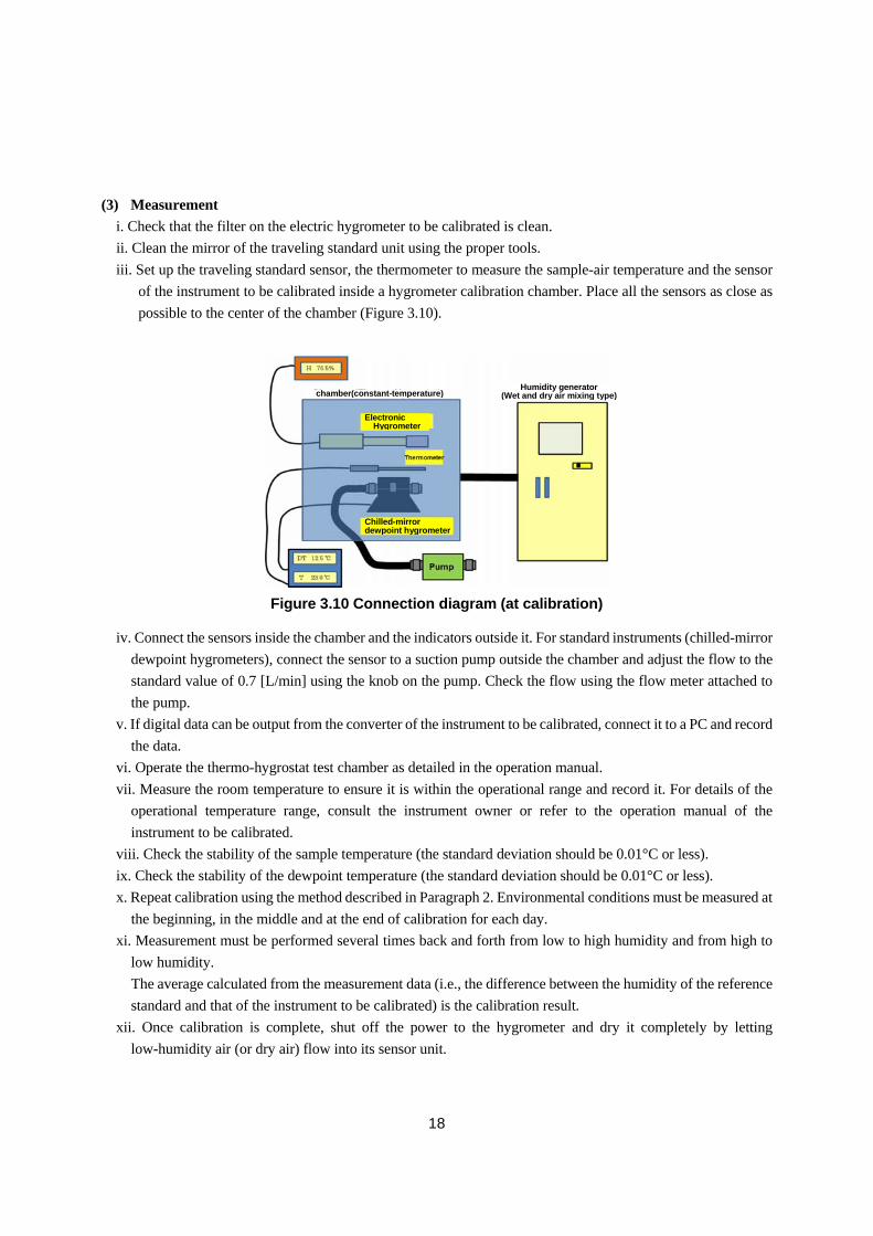
iii. Set up the traveling standard sensor, the thermometer to measure the sample-air temperature and the sensor
of the instrument to be calibrated inside a hygrometer calibration chamber. Place all the sensors as close as
possible to the center of the chamber (Figure 3.10).
iv. Connect the sensors inside the chamber and the indicators outside it. For standard instruments (chilled-mirror
dewpoint hygrometers), connect the sensor to a suction pump outside the chamber and adjust the flow to the
standard value of 0.7 [L/min] using the knob on the pump. Check the flow using the flow meter attached to
the pump.
v. If digital data can be output from the converter of the instrument to be calibrated, connect it to a PC and record
the data.
vi. Operate the thermo-hygrostat test chamber as detailed in the operation manual.
vii. Measure the room temperature to ensure it is within the operational range and record it. For details of the
operational temperature range, consult the instrument owner or refer to the operation manual of the
instrument to be calibrated.
viii. Check the stability of the sample temperature (the standard deviation should be 0.01°C or less).
ix. Check the stability of the dewpoint temperature (the standard deviation should be 0.01°C or less).
x. Repeat calibration using the method described in Paragraph 2. Environmental conditions must be measured at
the beginning, in the middle and at the end of calibration for each day.
xi. Measurement must be performed several times back and forth from low to high humidity and from high to
low humidity.
The average calculated from the measurement data (i.e., the difference between the humidity of the reference
standard and that of the instrument to be calibrated) is the calibration result.
xii. Once calibration is complete, shut off the power to the hygrometer and dry it completely by letting
low-humidity air (or dry air) flow into its sensor unit.
ElectronicHygrometer
Chilled-mirrordewpoint hygrometer
Humidity generator(Wet and dry air mixing type)chamber(constant-temperature)
Figure 3.10 Connection diagram (at calibration)