composite action in rcc and brick masonry - ijser · pdf filecomposite action in rcc and brick...
TRANSCRIPT
Composite Action in RCC and Brick MasonryPraveena Rao and Dr.B.Jena
ABSTRACT- In a wall with openings lintels are built, thus the load carried by lintels is transferred of the masonry in jambs. Lintel with masonryabove is a complex phenomenon known as the composite action. In this experimental work, the contribution of the brick masonry towards the loadcarrying capacity of the lintel is analysed in the composite action thus developed. Six specimens of sections (3 inches) 75 mm thick and (10 inches)250 mm wide R.C. lintels with 4 Nos. of 10mm diameter bars are provided for spanning openings of 4 feet and 6 feet. Shear reinforcementcomprising ties (90o bent) of 8mm diameter bars are provided at regular intervals throughout the span. These lintel-masonry test walls were testedto failure under flexure in the beam testing frame and their load-deflection curves were plotted. The failure mechanism and the cracking pattern ofthe specimen were identified as a major diagonal shear crack. The shear strength and the moment capacity of the specimens were calculated andcompared with the test results. The shear strength of the lintel-masonry specimens were calculated by adopting the methods by the British codes fordeep beams. Secondly, the empirical formula given by the Indian codes (IS 456:2000) for shear strength of beams without shear reinforcement wasmodified and adopted taking into account the compressive strength of masonry.
A relationship between the masonry units, mortar and masonry blocks given by a relation by A.W.Hendry et.al was adopted. Samples ofmasonry unit were tested in the 40 tonne UTM for the crushing strength of bricks when tested on the flat surface, on the side and the top edge of thebricks.
The basic objective of the work is to find the contribution of brick masonry towards the strength of the lintel in carrying the load abovethe openings in walls and thus acting as a structural member. Thus an alternative method of designing economic lintel sections can be adopted.
Index Terms- Composite action, brick masonry, load-deflection curves, RCC lintel, strength, shear failure.
——————————u————————
1. INTRODUCTION
omposite action of lintel with masonry is acomplex phenomenon and is governed by anumber of parameters. In a simply supported
wall-beam the load acting introduces tensile forces in thebeam and the arching action which creates a horizontalthrust at each abutment.In general, the stiffer the beam the greater the beam-bending moment since a larger proportion of the load willbe transmitted to the beam. Composite action cannot beachieved unless there is sufficient bond between the walland the beam to allow for the development of therequired shearing forces. The large compressive stressesnear the supports result in large frictional forces along theinterface of wall and lintel. The following are the majorfactors affecting it: (a) Bond/friction at the interface oflintel and masonry, (b) Crushing strength of masonry, (c)Shear strength of masonry, (d) Masonry bond, (e) Heightof masonry above lintel, (f) Reinforcement in lintel, and(g) Whether the masonry is already stressed to limit ornot.
2. LITERATURE REVIEW
Vermeltfoort and Schijndel [1] have made an attempt toassign material properties like shear strength andmodulus of elasticity randomly. They had experimentallytested the behaviour of a masonry wall with aprefabricated concrete lintel and simulated usingCOMSOL. With the help of COMSOL, they havemodelled the lintel-masonry interaction, including thevariation of mechanical properties over the volume of the
specimen. Three series of three lintel-wall combinationswere experimentally tested to failure, where the mainparameter was the support condition. The test walls had aspan of 2.8 meters; their height was 60mm for the lintelwith nine layers of masonry on top were tested with fourpoint bending test. The load at which the first crackappeared and the ultimate load was observed andverified after testing by observing load deformationgraphs.
Studies carried out at the Central BuildingResearch Institute(Roorkee) [2] on thin precast R.C.C.lintels in brick walls during 1964-65 has also shown thatthey act together, tension being taken by the lintel andcompression by the brickwork. Based on these studies, 7.5cm thick and 23 cm wide precast R.C. lintels with 3 Nos.10 mm diameter mild steel bars as main reinforcementwere recommended for spanning openings up to 1.8 m.provided the bricks used have minimum compressivestrength of 10 N/mm2, the mortar is not leaner than 1:6cement: sand mortar and height of masonry above thelintel is at least 45 cm. Twelve lintel masonry panels weremade and tested. Uniformly distributed load was appliedin stages on the panels. The strains, deflections anddevelopment of cracks were noted at each stage ofloading, till the panels failed. Masonry cubes made alongwith the panels were also tested in a 100 tonnes capacityUniversal Testing Machine to determine the stress-strainrelationship for the stresses in the masonry panels forcorresponding strains. The stress developed in thereinforcement even at the failure stage was found to beless than the permissible stress in steel. This indicates thata major portion of the load is transferred to the supportsby arch action developed in the brickwork. The ultimate
C
International Journal of Scientific & Engineering Research, Volume 7, Issue 1, January-2016 ISSN 2229-5518 297
IJSER © 2016 http://www.ijser.org
IJSER
load increased with the height of brickwork. For the sameheight, the load carrying capacity decreased withmasonry strength.
Hossain and Ali , have presented a linear elasticfinite element analysis of composite action betweenmasonry wall made from clay solid bricks and RCCsupporting beam. Isoparametric four noded rectangularelement with two degrees of freedom at each node wasused in this analysis. Initially the wall was considered asa homogenous continuum when coarse mesh was used inelement discretization. Finally, non-homogeneity of themasonry and concrete was incorporated in the model bydiscretising the bricks, mortar joints, steel reinforcementand the concrete separately along with their individualmaterial properties. They found that due to arch action,major portion of the distributed load applied at the top ofthe wall concentrates on a small portion of the beam nearthe supports. . There is a very large reduction of bendingmoment in the supporting beam due to the compositeaction of wall-beam structure. Although the load on thetop of the wall is uniformly distributed over the entirespan, due to composite action the maximum moment inthe beam does not occur at the middle of the span. Thischange of location of maximum bending moment in thesupporting beam is observed by previous investigators.In this study the maximum moment in the supportingbeam is 0.018 wL2 and is found to occur at a distance of0.14 L from the end of the support. The maximummoment in a simply supported due to uniformlydistributed load is given by Wl2 / 8 which occurs at themid span. But if, composite action of wall and supportingbeam is considered the moment at middle section of beamis obtained as 0.012 wL2, which is 1/10 th of the valueobtained from conventional formula.
3. MATERIALS
Cement used in the experiments was Portland SlagCement (PSC) conforming to IS 455-1989.
The aggregates are categorized into fineaggregates (particle size between 0.075mm and 4.75mm)and coarse aggregate (particle size larger than 4.75mm).Sand taken from river beds and pits is normally used asfine aggregate, while gravel and crushed rock arenormally used as coarse aggregate. Crushed granite of12.5mm & 20mm size are used as coarse aggregate, thesieve analysis of aggregates confirms to the specificationsof IS: 383-1970 as well as fine aggregates were used whichsatisfied the required properties for experimental workand conforms to zone as per the specification of IS: 383-1970.
Longitudinal reinforcement consisted of fourbars through of grade Fe500 throughout the span of10mm diameter along with ties of 8mm diameter equallyspaced. A tension test was conducted on the specimen of1 meter length cut from the bars used in the fabrication
and casting of the lintels. Three specimens were tested inUTM (40 tonnes capacity) and the average of the ultimatestrength of the three is considered.
The masonry was laid above the lintel specimenswith burnt clay bricks conforming to IS 1077:1992. Thebricks were tested for the compressive strength asspecified in IS 3495(part1): 1992. The bricks were acquiredfrom the same manufacturer for all the specimens testedto maintain uniformity of the properties of bricks used.The dimension of the bricks was (10 x 4.5 x 3) inches andthe percentage of water absorption was found to be 14%by weight of the bricks when immersed in water for aperiod of 24 hours.
4. EXPERIMENTAL PROGRAM
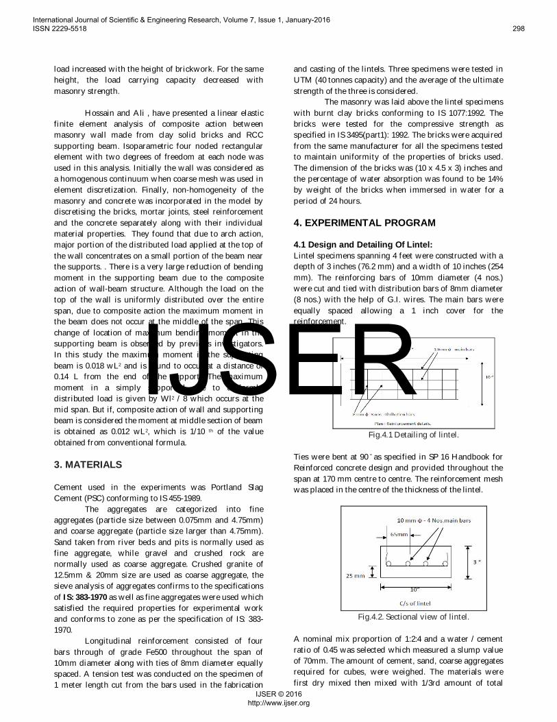
4.1 Design and Detailing Of Lintel:Lintel specimens spanning 4 feet were constructed with adepth of 3 inches (76.2 mm) and a width of 10 inches (254mm). The reinforcing bars of 10mm diameter (4 nos.)were cut and tied with distribution bars of 8mm diameter(8 nos.) with the help of G.I. wires. The main bars wereequally spaced allowing a 1 inch cover for thereinforcement.
Fig.4.1 Detailing of lintel.
Ties were bent at 90 ̊ as specified in SP 16 Handbook forReinforced concrete design and provided throughout thespan at 170 mm centre to centre. The reinforcement meshwas placed in the centre of the thickness of the lintel.
Fig.4.2. Sectional view of lintel.
A nominal mix proportion of 1:2:4 and a water / cementratio of 0.45 was selected which measured a slump valueof 70mm. The amount of cement, sand, coarse aggregatesrequired for cubes, were weighed. The materials werefirst dry mixed then mixed with 1/3rd amount of total
International Journal of Scientific & Engineering Research, Volume 7, Issue 1, January-2016 ISSN 2229-5518 298
IJSER © 2016 http://www.ijser.org
IJSER
water. Slump test is conducted to measure the degree ofworkability of mix. The cement, sand (F.A.) and coarseaggregates (C.A.) were thoroughly mixed in the required1:2:4 mix proportion in a concrete pan / paddle mixer.Uniform mixing of concrete should be ensured to getcorrect test results of the specimen. After mixing, concretewas placed in the beam mould in layers of a depth equalto approximately 1 inch. Each layer was manuallycompacted using ½ inch steel rod to eliminate voids in thespecimen. The lintel was de-moulded after a period of 24hours and kept on gunny bag curing for two weeks.
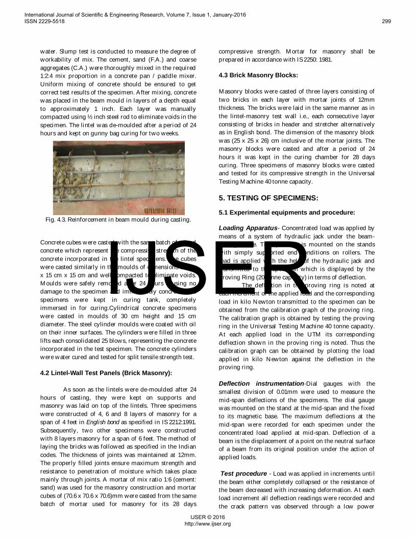
Fig. 4.3. Reinforcement in beam mould during casting.
Concrete cubes were casted with the same batch of mixedconcrete which represent the compressive strength of theconcrete incorporated in the lintel specimens. The cubeswere casted similarly in the moulds of dimensions 15 cmx 15 cm x 15 cm and well compacted to eliminate voids.Moulds were safely removed after 24 hours causing nodamage to the specimen and immediately concrete cubespecimens were kept in curing tank, completelyimmersed in for curing.Cylindrical concrete specimenswere casted in moulds of 30 cm height and 15 cmdiameter. The steel cylinder moulds were coated with oilon their inner surfaces. The cylinders were filled in threelifts each consolidated 25 blows, representing the concreteincorporated in the test specimen. The concrete cylinderswere water cured and tested for split tensile strength test.
4.2 Lintel-Wall Test Panels (Brick Masonry):
As soon as the lintels were de-moulded after 24hours of casting, they were kept on supports andmasonry was laid on top of the lintels. Three specimenswere constructed of 4, 6 and 8 layers of masonry for aspan of 4 feet in English bond as specified in IS 2212:1991.Subsequently, two other specimens were constructedwith 8 layers masonry for a span of 6 feet. The method oflaying the bricks was followed as specified in the Indiancodes. The thickness of joints was maintained at 12mm.The properly filled joints ensure maximum strength andresistance to penetration of moisture which takes placemainly through joints. A mortar of mix ratio 1:6 (cement:sand) was used for the masonry construction and mortarcubes of (70.6 x 70.6 x 70.6)mm were casted from the samebatch of mortar used for masonry for its 28 days
compressive strength. Mortar for masonry shall beprepared in accordance with IS 2250: 1981.
4.3 Brick Masonry Blocks:
Masonry blocks were casted of three layers consisting oftwo bricks in each layer with mortar joints of 12mmthickness. The bricks were laid in the same manner as inthe lintel-masonry test wall i.e., each consecutive layerconsisting of bricks in header and stretcher alternativelyas in English bond. The dimension of the masonry blockwas (25 x 25 x 26) cm inclusive of the mortar joints. Themasonry blocks were casted and after a period of 24hours it was kept in the curing chamber for 28 dayscuring. Three specimens of masonry blocks were castedand tested for its compressive strength in the UniversalTesting Machine 40 tonne capacity.
5. TESTING OF SPECIMENS:
5.1 Experimental equipments and procedure:
Loading Apparatus- Concentrated load was applied bymeans of a system of hydraulic jack under the beam-testing frame. The specimen is mounted on the standswith simply supported end conditions on rollers. Theload is applied with the help of the hydraulic jack andtransmitted to the specimen which is displayed by theProving Ring (20 tonne capacity) in terms of deflection.
The deflection in the proving ring is noted ateach increment of the applied load and the correspondingload in kilo Newton transmitted to the specimen can beobtained from the calibration graph of the proving ring.The calibration graph is obtained by testing the provingring in the Universal Testing Machine 40 tonne capacity.At each applied load in the UTM its correspondingdeflection shown in the proving ring is noted. Thus thecalibration graph can be obtained by plotting the loadapplied in kilo Newton against the deflection in theproving ring.
Deflection instrumentation-Dial gauges with thesmallest division of 0.01mm were used to measure themid-span deflections of the specimens. The dial gaugewas mounted on the stand at the mid-span and the fixedto its magnetic base. The maximum deflections at themid-span were recorded for each specimen under theconcentrated load applied at mid-span. Deflection of abeam is the displacement of a point on the neutral surfaceof a beam from its original position under the action ofapplied loads.
Test procedure - Load was applied in increments untilthe beam either completely collapsed or the resistance ofthe beam decreased with increasing deformation. At eachload increment all deflection readings were recorded andthe crack pattern vas observed through a low power
International Journal of Scientific & Engineering Research, Volume 7, Issue 1, January-2016 ISSN 2229-5518 299
IJSER © 2016 http://www.ijser.org
IJSER
illuminated magnifying glass and marked with ink.Before the next increment of load was applied, the loadand deflections were again recorded as a certain amountof load drop-off and deflection increase during therecording period was observed. After yielding and up tofailure, loads and deflections were recorded forincrements of mid-span deflection rather than load. Atvarious points throughout the test and afterwards,pictures were taken to allow the crack patterns. Thecontrol specimens were tested on completion of' thelintel-masonry panel test.
5. TESTS ON BRICKS:
5.1 Crushing Strength of Bricks
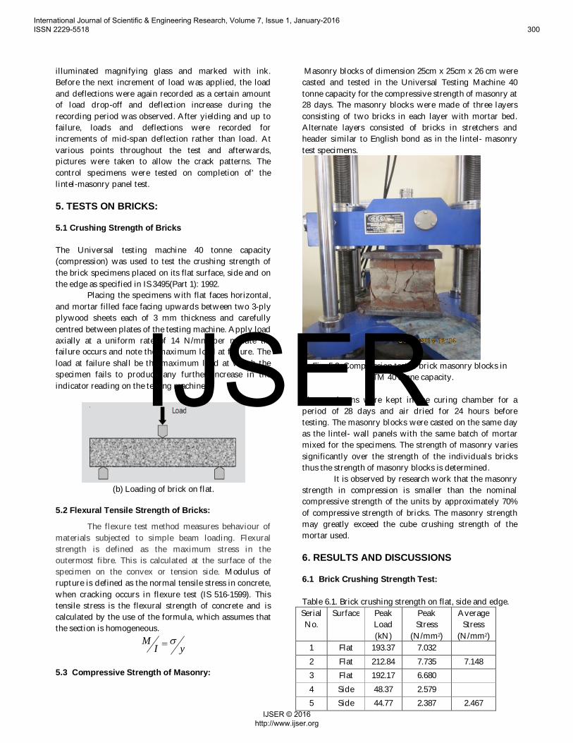
The Universal testing machine 40 tonne capacity(compression) was used to test the crushing strength ofthe brick specimens placed on its flat surface, side and onthe edge as specified in IS 3495(Part 1): 1992.
Placing the specimens with flat faces horizontal,and mortar filled face facing upwards between two 3-plyplywood sheets each of 3 mm thickness and carefullycentred between plates of the testing machine. Apply loadaxially at a uniform rate of 14 N/mm per minute tillfailure occurs and note the maximum load at failure. Theload at failure shall be the maximum load at which thespecimen fails to produce any further increase in theindicator reading on the testing machine.
(b) Loading of brick on flat.
5.2 Flexural Tensile Strength of Bricks:
The flexure test method measures behaviour ofmaterials subjected to simple beam loading. Flexuralstrength is defined as the maximum stress in theoutermost fibre. This is calculated at the surface of thespecimen on the convex or tension side. Modulus ofrupture is defined as the normal tensile stress in concrete,when cracking occurs in flexure test (IS 516-1599). Thistensile stress is the flexural strength of concrete and iscalculated by the use of the formula, which assumes thatthe section is homogeneous.
yIM s=
5.3 Compressive Strength of Masonry:
Masonry blocks of dimension 25cm x 25cm x 26 cm werecasted and tested in the Universal Testing Machine 40tonne capacity for the compressive strength of masonry at28 days. The masonry blocks were made of three layersconsisting of two bricks in each layer with mortar bed.Alternate layers consisted of bricks in stretchers andheader similar to English bond as in the lintel- masonrytest specimens.
Fig. 5.3. Compression test of brick masonry blocks inUTM 40 tonne capacity.
The specimens were kept in the curing chamber for aperiod of 28 days and air dried for 24 hours beforetesting. The masonry blocks were casted on the same dayas the lintel- wall panels with the same batch of mortarmixed for the specimens. The strength of masonry variessignificantly over the strength of the individuals bricksthus the strength of masonry blocks is determined.
It is observed by research work that the masonrystrength in compression is smaller than the nominalcompressive strength of the units by approximately 70%of compressive strength of bricks. The masonry strengthmay greatly exceed the cube crushing strength of themortar used.
6. RESULTS AND DISCUSSIONS
6.1 Brick Crushing Strength Test:
Table 6.1. Brick crushing strength on flat, side and edge.SerialNo.
Surface PeakLoad(kN)
PeakStress
(N/mm2)
AverageStress
(N/mm2)1 Flat 193.37 7.0322 Flat 212.84 7.735 7.1483 Flat 192.17 6.6804 Side 48.37 2.5795 Side 44.77 2.387 2.467
International Journal of Scientific & Engineering Research, Volume 7, Issue 1, January-2016 ISSN 2229-5518 300
IJSER © 2016 http://www.ijser.org
IJSER
6 Side 45.57 2.4367 End 20.57 2.385
8 End 19.27 2.234 2.1859 End 15.97 1.936
Thus, it is observed that the crushing strength of brick isfound to be the maximum, when tested on the flatsurface. Where as it is the minimum when loaded on thetop with a reduction of about 70%.
6.2 Brick Masonry Block Compression Test:
Table 6.2. Compressive strength of masonry blocks.Serial
No.
Dimension(cm) Wt(kg)
PeakLoad(kN)
PeakStress
(N/mm2)
1 24.5 x 24.5 x 26 29.9 97.6 1.6262 25 x 25 x 26 30.3 124.6 1.993 24.5 x 24 x 27 32.2 135.2 2.29
AvgStress
=
1.968
It can be observed from the above two tests carried out,that the compressive strength of individual units ofmasonry is about 80% higher than the compressivestrength of a block of masonry. It can be concluded thatthe reduction in strength is majorly due the occurrence ofjoints in masonry blocks which act as the weak zones offailure.
6.3 Brick Flexural Tensile Strength Test:
Table 6.3. Flexural tensile strength of brick on flat andside.Sl Wt
(kg)Dimensio
n (cm)Surface Peak
Load(kN)
Stress(N/mm2 )
Average
Stress
(N/mm2
)1 3.034 26 x 11.5 x
7Flat 2.2 2.46
2 3.52 25 x 11.5 x7
Flat 2.2 2.34 2.46
3 3.257 26 x 11 x 7 Flat 2.2 2.574 3.309 26 x 11.5 x
7.5Side 3.3 2.096
5 3.105 25 x 10.5 x7.5
Side 3.3 2.39 2.54
6 3.454 26 x 11.5 x7
Side 4.5 3.06
6.4 Mortar (1:6) Cubes Compressive Strength Test:
Table6. 4. Compressive strength of Mortar cubes.SerialNo.
Weight (kg) Peak Load(kN)
Peak Stress(N/mm2)
1 2.119 84.1 8.41
2 2.104 101.7 10.17
3 2.105 101.7 10.17
4 1.979 65.4 6.54
5 2.103 100.2 10.02
Average Stress=
9.062
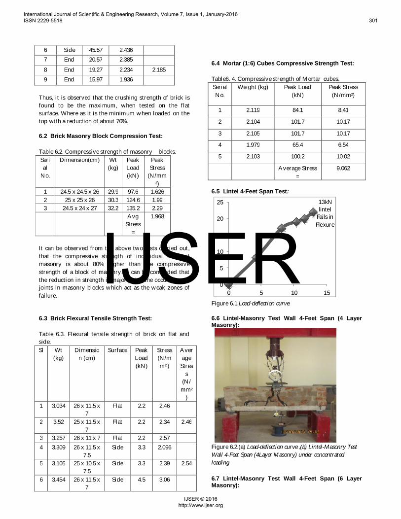
6.5 Lintel 4-Feet Span Test:
13kNlintel
Fails inFlexure
0
5
10
15
20
25
0 5 10 15
Figure 6.1.Load-deflection curve.
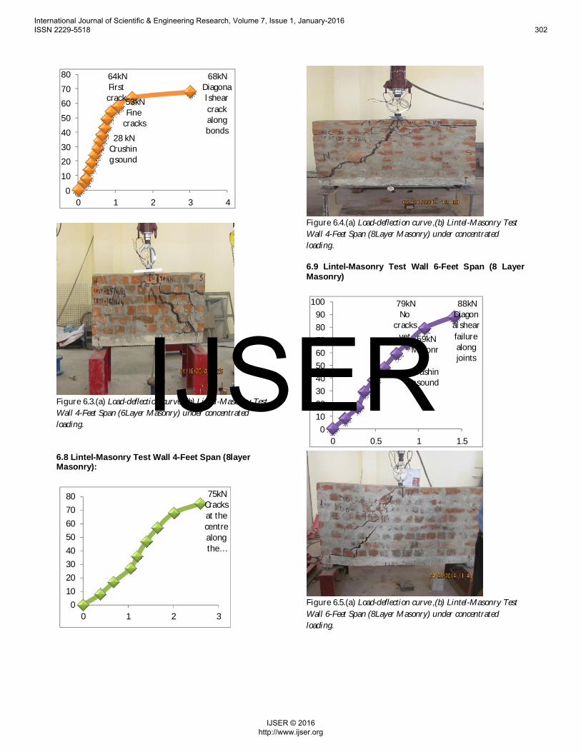
6.6 Lintel-Masonry Test Wall 4-Feet Span (4 LayerMasonry):
Figure 6.2.(a) Load-deflection curve ,(b) Lintel-Masonry TestWall 4-Feet Span (4Layer Masonry) under concentratedloading
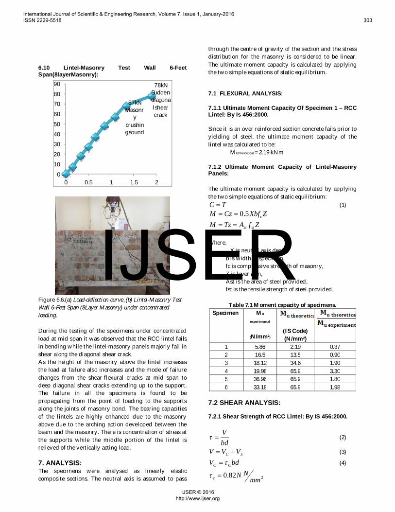
6.7 Lintel-Masonry Test Wall 4-Feet Span (6 LayerMasonry):
International Journal of Scientific & Engineering Research, Volume 7, Issue 1, January-2016 ISSN 2229-5518 301
IJSER © 2016 http://www.ijser.org
IJSER
28 kNCrushing sound
53kNFine
cracks
64kNFirst
crack
68kNDiagonal shearcrackalongbonds
0
10
20
30
40
50
60
70
80
0 1 2 3 4
Figure 6.3.(a) Load-deflection curve ,(b) Lintel-Masonry TestWall 4-Feet Span (6Layer Masonry) under concentratedloading.
6.8 Lintel-Masonry Test Wall 4-Feet Span (8layerMasonry):
75kNCracksat thecentrealongthe …
01020304050607080
0 1 2 3
Figure 6.4.(a) Load-deflection curve ,(b) Lintel-Masonry TestWall 4-Feet Span (8Layer Masonry) under concentratedloading.
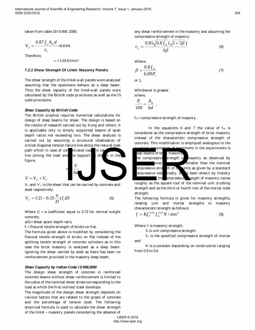
6.9 Lintel-Masonry Test Wall 6-Feet Span (8 LayerMasonry)
59kNMasonr
ycrushing sound
79kNNo
cracksyet
88kNDiagonal shearfailurealongjoints
0102030405060708090
100
0 0.5 1 1.5
Figure 6.5.(a) Load-deflection curve ,(b) Lintel-Masonry TestWall 6-Feet Span (8Layer Masonry) under concentratedloading.
International Journal of Scientific & Engineering Research, Volume 7, Issue 1, January-2016 ISSN 2229-5518 302
IJSER © 2016 http://www.ijser.org
IJSER
6.10 Lintel-Masonry Test Wall 6-FeetSpan(8layerMasonry):
57kNMasonr
ycrushing sound
78kNSuddendiagonal shearcrack
0
10
20
30
40
50
60
70
80
90
0 0.5 1 1.5 2
Figure 6.6.(a) Load-deflection curve ,(b) Lintel-Masonry TestWall 6-Feet Span (8Layer Masonry) under concentratedloading.
During the testing of the specimens under concentratedload at mid span it was observed that the RCC lintel failsin bending while the lintel-masonry panels majorly fail inshear along the diagonal shear crack.As the height of the masonry above the lintel increasesthe load at failure also increases and the mode of failurechanges from the shear-flexural cracks at mid span todeep diagonal shear cracks extending up to the support.The failure in all the specimens is found to bepropagating from the point of loading to the supportsalong the joints of masonry bond. The bearing capacitiesof the lintels are highly enhanced due to the masonryabove due to the arching action developed between thebeam and the masonry. There is concentration of stress atthe supports while the middle portion of the lintel isrelieved of the vertically acting load.
7. ANALYSIS:The specimens were analysed as linearly elasticcomposite sections. The neutral axis is assumed to pass
through the centre of gravity of the section and the stressdistribution for the masonry is considered to be linear.The ultimate moment capacity is calculated by applyingthe two simple equations of static equilibrium.
7.1 FLEXURAL ANALYSIS:
7.1.1 Ultimate Moment Capacity Of Specimen 1 – RCCLintel: By Is 456:2000.
Since it is an over reinforced section concrete fails prior toyielding of steel, the ultimate moment capacity of thelintel was calculated to be:
MUtheoretical = 2.19 kNm
7.1.2 Ultimate Moment Capacity of Lintel-MasonryPanels:
The ultimate moment capacity is calculated by applyingthe two simple equations of static equilibrium:
TC = (1)ZXbfCzM c5.0==
ZfATzM stst==
Where,X is neutral axis dept,
b is width of specimen, fc is compressive strength of masonry, Z is lever arm, Ast is the area of steel provided, fst is the tensile strength of steel provided.
Table 7.1 Moment capacity of specimens.Specimen Mu
experimental
(N/mm2)(IS Code)(N/mm2)
1 5.86 2.19 0.372 16.5 13.5 0.903 18.12 34.6 1.904 19.98 65.9 3.305 36.96 65.9 1.806 33.18 65.9 1.98
7.2 SHEAR ANALYSIS:
7.2.1 Shear Strength of RCC Lintel: By IS 456:2000.
bdV
=t (2)
SC VVV += (3)
bdV CC t= (4)
282.0 mmNNc =t
International Journal of Scientific & Engineering Research, Volume 7, Issue 1, January-2016 ISSN 2229-5518 303
IJSER © 2016 http://www.ijser.org
IJSER
taken from table 19 IS 456: 2000.
v
svyS s
dAfV
87.0= =6.8 kN
Therefore, τ = 1.53 N/mm2
7.2.2 Shear Strength Of Lintel- Masonry Panels:
The shear strength of the lintel-wall panels were analysedassuming that the specimens behave as a deep beam.Thus the shear capacity of the lintel-wall panels werecalculated by the British code provisions as well as the IScode provisions.
Shear Capacity by British Code:The British practice requires numerical calculations fordesign of deep beams for shear. The design is based onthe results of research carried out by Kong and others. Itis applicable only to simply supported beams of spandepth ratios not exceeding two. The shear analysis iscarried out by assuming a structural idealisation ofcritical diagonal tension failure line along the natural loadpath which in case of concentrated loads is taken as theline joining the load and the support as shown in thefigure.
bdV
=t
SC VVV +=Vc and V s is the shear that can be carried by concrete andsteel respectively.
tDfDaCV tC )35.01( -= (5)
Where C = a coefficient equal to 0.72 for normal weightconcrete,a/D= shear span/ depth ratio,ft = flexural tensile strength of bricks on flat.The formula given above is modified by considering theflexural tensile strength of bricks on flat instead of thesplitting tensile strength of concrete cylinders as in thiscase the brick masonry is analysed as a deep beam.Ignoring the shear carried by steel as there has been noreinforcement provided in the masonry deep beam.
Shear Capacity by Indian Code: IS 456:2000The design shear strength of concrete in reinforcedconcrete beams without shear reinforcement is limited tothe value of the nominal shear stress corresponding to theload at which the first inclined crack develops.The magnitude of the design shear strength depends onvarious factors that are related to the grade of concreteand the percentage of tension steel. The followingempirical formula is used to calculate the shear strengthof the lintel – masonry panels considering the absence of
any shear reinforcement in the masonry and assuming thecompressive strength of masonry:
bb
t6
)51(8.085.0 += ck
C
f(6)
Where,
t
ck
Pf
89.68.0
=b (7)
or 1,
Whichever is greater.where,
bdAP stt =
100 ,
fck = compressive strength of masonry.
In the equations 6 and 7 the value of fck isconsidered as the compressive strength of brick masonryinstead of the characteristic compressive strength ofconcrete. This modification is employed analogous to thepractical composition of specimens in the experiments isdeep beams of brick masonry.The compressive strength of masonry as observed byresearchers was found to be smaller than the nominalcompressive strength of the units as given by a standardcompressive test. Finally, it has been shown by Hendryet.al. [11] that the compressive strength of masonry variesroughly as the square root of the nominal unit crushingstrength and as the third or fourth root of the mortar cubestrength.The following formula is given for masonry strengths,relating unit and mortar strengths to masonrycharacteristic strength as follows:
225.065.0 / mmNfKff mb= (8)
Where, f is masonry strength, fb is unit compressive strength, fm is the specified compressive strength of mortarand K is a constant depending on construction rangingfrom 0.6 to 0.4.
International Journal of Scientific & Engineering Research, Volume 7, Issue 1, January-2016 ISSN 2229-5518 304
IJSER © 2016 http://www.ijser.org
IJSER
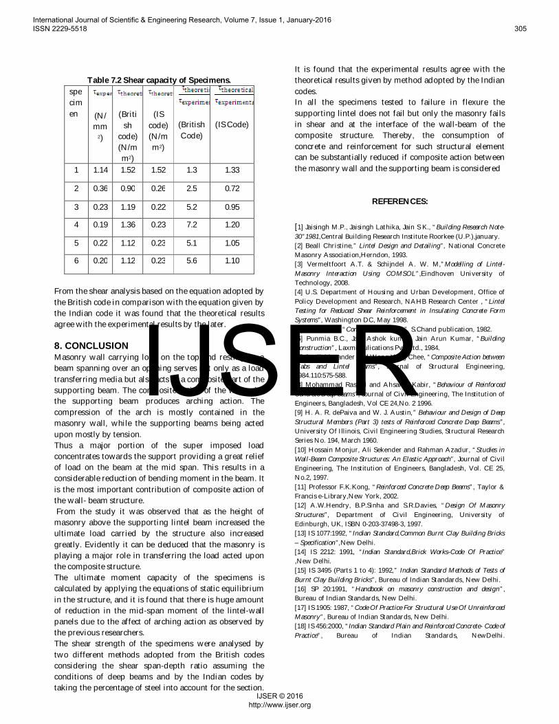
Table 7.2 Shear capacity of Specimens.specimen (N/
mm2)
(British
code)(N/mm2)
(IScode)(N/mm2)
(BritishCode)
(IS Code)
1 1.14 1.52 1.52 1.3 1.33
2 0.36 0.90 0.26 2.5 0.72
3 0.23 1.19 0.22 5.2 0.95
4 0.19 1.36 0.23 7.2 1.20
5 0.22 1.12 0.23 5.1 1.05
6 0.20 1.12 0.23 5.6 1.10
From the shear analysis based on the equation adopted bythe British code in comparison with the equation given bythe Indian code it was found that the theoretical resultsagree with the experimental results by the later.
8. CONCLUSIONMasonry wall carrying load on the top and resting on abeam spanning over an opening serves not only as a loadtransferring media but also acts as a composite part of thesupporting beam. The composite action of the wall withthe supporting beam produces arching action. Thecompression of the arch is mostly contained in themasonry wall, while the supporting beams being actedupon mostly by tension.Thus a major portion of the super imposed loadconcentrates towards the support providing a great reliefof load on the beam at the mid span. This results in aconsiderable reduction of bending moment in the beam. Itis the most important contribution of composite action ofthe wall- beam structure. From the study it was observed that as the height ofmasonry above the supporting lintel beam increased theultimate load carried by the structure also increasedgreatly. Evidently it can be deduced that the masonry isplaying a major role in transferring the load acted uponthe composite structure.The ultimate moment capacity of the specimens iscalculated by applying the equations of static equilibriumin the structure, and it is found that there is huge amountof reduction in the mid-span moment of the lintel-wallpanels due to the affect of arching action as observed bythe previous researchers.The shear strength of the specimens were analysed bytwo different methods adopted from the British codesconsidering the shear span-depth ratio assuming theconditions of deep beams and by the Indian codes bytaking the percentage of steel into account for the section.
It is found that the experimental results agree with thetheoretical results given by method adopted by the Indiancodes.In all the specimens tested to failure in flexure thesupporting lintel does not fail but only the masonry failsin shear and at the interface of the wall-beam of thecomposite structure. Thereby, the consumption ofconcrete and reinforcement for such structural elementcan be substantially reduced if composite action betweenthe masonry wall and the supporting beam is considered
REFERENCES:
[1] Jaisingh M.P., Jaisingh Lathika, Jain S K., “Building Research Note-30”1981,Central Building Research Institute Roorkee (U.P.),january.[2] Beall Christine,” Lintel Design and Detailing”, National ConcreteMasonry Association,Herndon, 1993.[3] Vermeltfoort A.T. & Schijndel A. W. M,”Modelling of Lintel-Masonry Interaction Using COMSOL”,Eindhoven University ofTechnology, 2008.[4] U.S. Department of Housing and Urban Development, Office ofPolicy Development and Research, NAHB Research Center , “LintelTesting for Reduced Shear Reinforcement in Insulating Concrete FormSystems”, Washington DC, May 1998.[5] Shetty M.S., “Concrete Technology”, S.Chand publication, 1982.[6] Punmia B.C., Jain Ashok kumar, Jain Arun Kumar, “BuildingConstruction”, Laxmi Pulications Pvt. Ltd., 1984.[7] Coull Alexander and Wong Yang Chee, “Composite Action betweenSlabs and Lintel Beams”, Journal of Structural Engineering,1984.110:575-588.[8] Mohammad Rashid and Ahsanul Kabir, “Behaviour of ReinforcedConcrete Deep beams”, Journal of Civil Engineering, The Institution ofEngineers, Bangladesh, Vol CE 24,No. 2 1996.[9] H. A. R. dePaiva and W. J. Austin,” Behaviour and Design of DeepStructural Members (Part 3) tests of Reinforced Concrete Deep Beams”,University Of Illinois, Civil Engineering Studies, Structural ResearchSeries No. 194, March 1960.[10] Hossain Monjur, Ali Sekender and Rahman Azadur, “Studies inWall-Beam Composite Structures: An Elastic Approach”, Journal of CivilEngineering, The Institution of Engineers, Bangladesh, Vol. CE 25,No.2, 1997.[11] Professor F.K.Kong, “Reinforced Concrete Deep Beams”, Taylor &Francis e-Library,New York, 2002.[12] A.W.Hendry, B.P.Sinha and S.R.Davies, “Design Of MasonryStructures”, Department of Civil Engineering, University ofEdinburgh, UK, ISBN 0-203-37498-3, 1997.[13] IS 1077:1992, “Indian Standard,Common Burnt Clay Building Bricks– Specification”,New Delhi.[14] IS 2212: 1991, “Indian Standard,Brick Works-Code Of Practice”,New Delhi.[15] IS 3495 (Parts 1 to 4): 1992,” Indian Standard Methods of Tests ofBurnt Clay Building Bricks”, Bureau of Indian Standards, New Delhi.[16] SP 20:1991, “Handbook on masonry construction and design”,Bureau of Indian Standards, New Delhi.[17] IS 1905: 1987, “Code Of Practice For Structural Use Of UnreinforcedMasonry”, Bureau of Indian Standards, New Delhi.[18] IS 456:2000, “Indian Standard Plain and Reinforced Concrete- Code ofPractice”, Bureau of Indian Standards, NewDelhi.
International Journal of Scientific & Engineering Research, Volume 7, Issue 1, January-2016 ISSN 2229-5518 305
IJSER © 2016 http://www.ijser.org
IJSER