behaviour of composite structure of rcc and … · index terms: composite structure, flyash brick...
TRANSCRIPT

International Journal of Application or Innovation in Engineering & Management (IJAIEM) Web Site: www.ijaiem.org Email: [email protected]
Volume 6, Issue 5, May 2017 ISSN 2319 - 4847
Volume 6, Issue 5, May 2017 Page 173
ABSTRACT An attempt is made to prevent shear failure in composite structure of RCC lintel and flyash brick masonry above it. Hear we consider RCC lintel and the flyash brick masonry altogether as a composite structure. In a wall openings with the lintel beam and masonry above, the two components act together in supporting the load. The composite action of lintel with masonry above is a complex phenomenon. RCC Lintel specimen of spanning 1.5 meter were constructed with the depth of 101.6 mm (4 inches) and a width of 228.6 mm (9 inches). The reinforced bars of 8mm diameter (4 nos.) were cut and tied with distribution bas of 6mm diameter (8 nos.) with the help of G.I. wires. In addition, 3nos. of concrete cube of size 150mm×150mm×150mm were tested and the compressive strength is calculated, relating to the RCC lintel-beam. Three specimens of RCC lintel (of same cross section) and brick masonry above it were tested, from that thespecimens were cast with masonry above the lintel up to three, six and nine layers in English bond of flyash brick masonry. This lintel-masonry walls were tested to failure under two point load and their load deflection curve was plotted. And the comparative study of theoretical and experimental shear strength has been done. Index Terms: composite structure, flyash brick masonry, shear failure, RCC lintel, load deflection curve, bending moment and shear force diagram
1. INTRODUCTION A lintel is a horizontal beam member placed across the openings in the wall. Lintels were ordinarily designed only to carry out triangular load of masonry. And in that the span of the beam represent as the base of triangular load at the opening of the window or door. Lintels are easy and simple to construct, contrasting the arches, the beams and the lintels both together perform as flexural members which are straddling between the two supports. Lintels are generally designed to carry out its dead weight and the weight of masonry which are above the lintel. But the lintel which are RCC beam along with masonry work on it can be treated as composite beam carrying its dead weight plus the load are coming from slab and other load. The masonry work beyond the triangle are considered to be transfer as support through arch action.
2. LITERATURE REVIEW M.P.Jaisingh, Lathikajaisingh, S.K. jain in 1981[4] on thin precast R.C.C. lintels in brick walls during 1964-65 has also shown that they act together, tension being taken by the lintel and compression by the brickwork Based on these studies, 7.5 cm thick and 23 cm wide precast R.C. lintels with 3 Nos. 10 mm diameter mild steel bars as main reinforcement were recommended for spanning openings up to 1.8 m. if the bricks utilized have least compressive strength of 10 N/mm2, the mortar is not leaner than 1:6 cement: sand mortar and height of masonry over the lintel is at least 45 cm. such thin precast lintels are being received by many construction departments. Bricks having three different strengths, 3 N/mm2, 4 N/mm2 and 6 N/mm2 approximately were used in the tests The cement: sand mortar proportions used in the tests were 1:6 and while 1:8 the height of masonry above the lintels was kept as 30 cm and 45 cm. In all, twelve lintel masonry panels were made and tested. Uniformly distributed load was applied in stages on the panels. The strains, deflections and development of cracks were noted at each stage of loading, till the panels failed. Masonry cubes made along with the panels were also tested in a 100 tonnes capacity Universal Testing Machine to determine the stress-strain relationship for the stresses in the masonry panels for corresponding strains. The first cracks started at the top of the masonry above the edges of the opening and extended downwards and outwards at an angle of about 70° to the horizontal. The development of these cracks appeared to be mainly due to the intensity of shear stress developed in brick-work near edges of openings being more than the shear strength of brickwork. As the load was increased, cracks also extended and in almost all cases, the failure occurred by the
BEHAVIOUR OF COMPOSITE STRUCTURE OF RCC AND FLYASH BRICK MASONRY
SweetaMohanty1, Dr.B.Jena2 1Civil Department, Bhubaneswar engineering college /BijuPatnaik University of Technology, India
2Civil Department, School of Civil Engineering, KIIT University, India

International Journal of Application or Innovation in Engineering & Management (IJAIEM) Web Site: www.ijaiem.org Email: [email protected]
Volume 6, Issue 5, May 2017 ISSN 2319 - 4847
Volume 6, Issue 5, May 2017 Page 174
extension of these cracks to the full depth of brick-work and separation of horizontal joint between lintel and brickwork near the supports . The load at first crack varied from 45% to 75% of the ultimate load. The actual failure loads were found to be 1.6 to 2.6 times the ultimate load computed forthe panels, considering them as reinforced brick beams. This indicates that at least part of the load is transmitted by arch action. The maximum deflection recorded at the penultimate stage of loading was found to be 1 in 232 to 1 in 381 ofthe span. This variation in deflection is due to difference in strength and height of masonry above lintel. Coull and Wong in 1984[7]represented the relative influences of a range of structural parameters on the stiffness and effective flanges width of the composite coupling beam. For the normal range of structural dimensions encountered in practice, the slab width, lintel width, and lintel depth have little influence on the effective flanges width. The composite stiffness ratio and effective flange width increase significantly with the wall openings width. The influence of elastic lintel wall junction deformation may be allowed for in the calculation of the composite stiffness by increasing the clean span of the lintel by a length equal to the lintel depth. Significant reductions in the wind stresses and deflections in the walls may be achieved by including the composite action when the lintel is relatively flexible. A.W. Hendry, B.P.Sinha and S.R.Davies in 1997[5], made a report on design of masonry structure stating structural design in masonry requires a clear understanding of the behaviour of the mortar material under various stress condition. According to their result higher compressive stresses in a brick work bed joint because of the lateral restraint on its deformation from the unit. Md M Sazzad, M MYounus Ali, S M NizamudDoulah in 2002[9], made a report on study of behaviour of reinforcement concrete deep beam under two points loading and the effect of shear reinforcement. They investigated the influence of variation of web reinforcement spacing both in vertical and horizontal on the shear strength of the deep R.C beam. They also investigated the general trend in crack pattern, the mode of failure of deep R.C. beam and the load deflection characteristics under two-point load. They observed that under two-point load, the first cracks are the diagonal cracks which are to be observed in the clear span of the deep beam. In deeper beams, diagonal cracks are developed first and in shallower beam flexural cracks developed first.
3. EXPERIMENT PROCEDURE AND OBSERVATION 3.1 Test On Brick Masonry Blocks Masonry blocks were casted of three layers consisting of two bricks. The bricks were laid in the same manner as in the lintel masonry test wall in English bond. The masonry blocks were casted and after period of 24 hours it was kept in the curing chamber for 28 days.
Figure 1 test Of Brick-Masonry Under Compression
International Journal of Application or Innovation in Engineering & Management (IJAIEM) Web Site: www.ijaiem.org Email: [email protected]
Volume 6, Issue 5, May 2017 ISSN 2319 - 4847
Volume 6, Issue 5, May 2017 Page 175
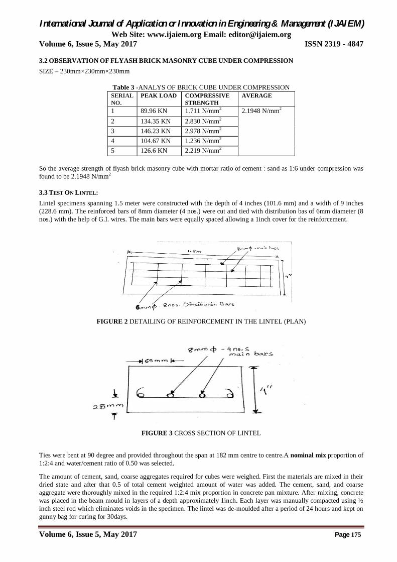
3.2 OBSERVATION OF FLYASH BRICK MASONRY CUBE UNDER COMPRESSION SIZE – 230mm×230mm×230mm
Table 3 -ANALYS OF BRICK CUBE UNDER COMPRESSION SERIAL NO.
PEAK LOAD COMPRESSIVE STRENGTH
AVERAGE
1 89.96 KN 1.711 N/mm2 2.1948 N/mm2 2 134.35 KN 2.830 N/mm2
3 146.23 KN 2.978 N/mm2
4 104.67 KN 1.236 N/mm2
5 126.6 KN 2.219 N/mm2
So the average strength of flyash brick masonry cube with mortar ratio of cement : sand as 1:6 under compression was found to be 2.1948 N/mm2
3.3 TEST ON LINTEL: Lintel specimens spanning 1.5 meter were constructed with the depth of 4 inches (101.6 mm) and a width of 9 inches (228.6 mm). The reinforced bars of 8mm diameter (4 nos.) were cut and tied with distribution bas of 6mm diameter (8 nos.) with the help of G.I. wires. The main bars were equally spaced allowing a 1inch cover for the reinforcement.
FIGURE 2 DETAILING OF REINFORCEMENT IN THE LINTEL (PLAN)
FIGURE 3 CROSS SECTION OF LINTEL
Ties were bent at 90 degree and provided throughout the span at 182 mm centre to centre.A nominal mix proportion of 1:2:4 and water/cement ratio of 0.50 was selected.
The amount of cement, sand, coarse aggregates required for cubes were weighed. First the materials are mixed in their dried state and after that 0.5 of total cement weighted amount of water was added. The cement, sand, and coarse aggregate were thoroughly mixed in the required 1:2:4 mix proportion in concrete pan mixture. After mixing, concrete was placed in the beam mould in layers of a depth approximately 1inch. Each layer was manually compacted using ½ inch steel rod which eliminates voids in the specimen. The lintel was de-moulded after a period of 24 hours and kept on gunny bag for curing for 30days.

International Journal of Application or Innovation in Engineering & Management (IJAIEM) Web Site: www.ijaiem.org Email: [email protected]
Volume 6, Issue 5, May 2017 ISSN 2319 - 4847
Volume 6, Issue 5, May 2017 Page 176
FIGURE 4PLACEMENT OF REINFORCED AND CONCRETE IN THE BEAM MOULD
3.4 OBSERVATION OF LINTEL
FIGURE 5TESTING OF LINTEL
Span= 1.5m
Table 2 -TEST RESULT FOR SPECIMEN 1 SUBJECTED TO TWO POINT LOAD
Serial no.
Provingring reading
Corresponding Load in KN
Deflection in Dial Gauge(mm)
Remarks
1 0 0 0 2 25 7.14 2.87 3 42 12 3.68
4 57 16.28 6.90 Hair crack 5 77 22 8.47
6 86 24.57 15.06 Failed

International Journal of Application or Innovation in Engineering & Management (IJAIEM) Web Site: www.ijaiem.org Email: [email protected]
Volume 6, Issue 5, May 2017 ISSN 2319 - 4847
Volume 6, Issue 5, May 2017 Page 177
FIGURE 6 - Bending Moment And Shear Force Diagram
FIGURE 7-Load And Deflection Curve
3.4.1 (a) Theoretical value of Ultimate Moment Capacity for RCC Lintel (by IS-1456:2000)
b
d

International Journal of Application or Innovation in Engineering & Management (IJAIEM) Web Site: www.ijaiem.org Email: [email protected]
Volume 6, Issue 5, May 2017 ISSN 2319 - 4847
Volume 6, Issue 5, May 2017 Page 178
Since it is an over reinforced section concrete fails prior to yielding of steel, the ultimate moment capacity of the lintel is Mu theoretical = 1.815×10⁶ N mm 3.4.1 (b) Experimental value of ultimate moment capacity for RCC lintel:
Table 3-Moment Capacity Of Rcc Lintel
3.4.2 (a) Theoretical value of Shear strength of RCC Lintel By: IS:456-2000 :
International Journal of Application or Innovation in Engineering & Management (IJAIEM) Web Site: www.ijaiem.org Email: [email protected]
Volume 6, Issue 5, May 2017 ISSN 2319 - 4847
Volume 6, Issue 5, May 2017 Page 179
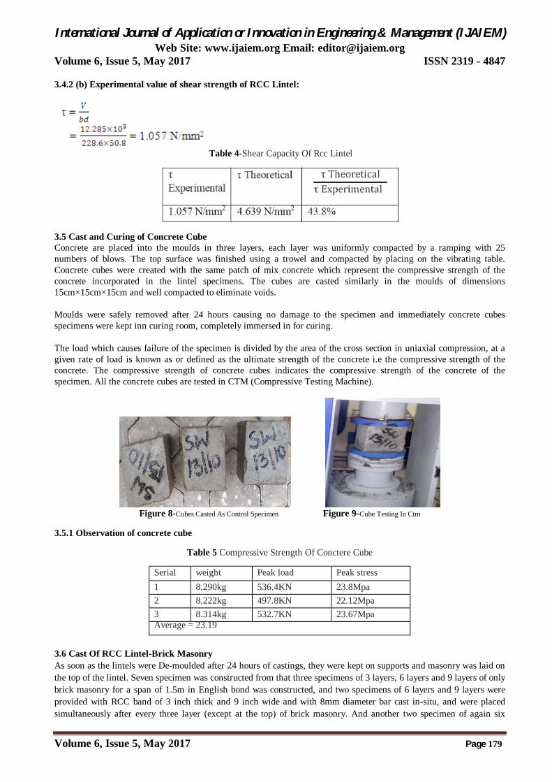
3.4.2 (b) Experimental value of shear strength of RCC Lintel:
Table 4-Shear Capacity Of Rcc Lintel
3.5 Cast and Curing of Concrete Cube Concrete are placed into the moulds in three layers, each layer was uniformly compacted by a ramping with 25 numbers of blows. The top surface was finished using a trowel and compacted by placing on the vibrating table. Concrete cubes were created with the same patch of mix concrete which represent the compressive strength of the concrete incorporated in the lintel specimens. The cubes are casted similarly in the moulds of dimensions 15cm×15cm×15cm and well compacted to eliminate voids. Moulds were safely removed after 24 hours causing no damage to the specimen and immediately concrete cubes specimens were kept inn curing room, completely immersed in for curing. The load which causes failure of the specimen is divided by the area of the cross section in uniaxial compression, at a given rate of load is known as or defined as the ultimate strength of the concrete i.e the compressive strength of the concrete. The compressive strength of concrete cubes indicates the compressive strength of the concrete of the specimen. All the concrete cubes are tested in CTM (Compressive Testing Machine).
Figure 8-Cubes Casted As Control Specimen Figure 9-Cube Testing In Ctm
3.5.1 Observation of concrete cube
Table 5 Compressive Strength Of Conctere Cube
Serial no.
weight Peak load Peak stress 1 8.290kg 536.4KN 23.8Mpa 2 8.222kg 497.8KN 22.12Mpa 3 8.314kg 532.7KN 23.67Mpa Average = 23.19
3.6 Cast Of RCC Lintel-Brick Masonry As soon as the lintels were De-moulded after 24 hours of castings, they were kept on supports and masonry was laid on the top of the lintel. Seven specimen was constructed from that three specimens of 3 layers, 6 layers and 9 layers of only brick masonry for a span of 1.5m in English bond was constructed, and two specimens of 6 layers and 9 layers were provided with RCC band of 3 inch thick and 9 inch wide and with 8mm diameter bar cast in-situ, and were placed simultaneously after every three layer (except at the top) of brick masonry. And another two specimen of again six

International Journal of Application or Innovation in Engineering & Management (IJAIEM) Web Site: www.ijaiem.org Email: [email protected]
Volume 6, Issue 5, May 2017 ISSN 2319 - 4847
Volume 6, Issue 5, May 2017 Page 180
layers and nine layers were provided with RCC band of same cross section with 8mm diameter bar were pre-cast and placed simultaneously after three layer(except at the top) was constructed.
Bricks shall be placed above the full bed of mortar and while placing, it should be slightly pressed such that the mortar should gets into all the pores of the brick surface and to ensure adhesion. All joints i.e wall and cross joints should be packed and flushed properly with cement mortar so that no hollow or spaces should be left. Properly filled joints ensure maximum strength and resistance to moisture, which mainly penetrates in the joints. In brick work the cross joints shall not be nearer than a quarter of the brick length from those in the course below or above it. The primary objective of the bond is to give strength to masonry. A mortar of mix ratio 1:6 (Cement: Sand) was used for the masonry construction and mortar cubes were casted from the same batch of mortar used for masonry for its 28 days compressive strength. Properties of mortar which are use in masonry are: Workability, Rate of stiffening, Strength, Resistance to rain penetration and durability.
FIGURE 10-CAST OF RCC LINTEL-BRICK MASONRY
3.6.1 Observation of RCC lintel-Brick Masonry (3 layers)
Figure11-Testing Of Lintel-Brick Masonry (3 Layers)
Table 4- Table 6-TEST RESULT FOR SPECIMEN 2 SUBJECTED TO TWO POINT LOAD
Serial no.
Provingring reading
Corresponding Load in KN
Deflection in Dial Gauge(mm)
Remarks
1 0 0 0 2 30 8.57 0.11 3 45 12.85 0.19 4 66 18.86 0.28 5 85 24.29 0.42 6 105 30 2.17 Failure in joint

International Journal of Application or Innovation in Engineering & Management (IJAIEM) Web Site: www.ijaiem.org Email: [email protected]
Volume 6, Issue 5, May 2017 ISSN 2319 - 4847
Volume 6, Issue 5, May 2017 Page 181
Figure 12- Bending Moment And Shear Force Diagram
Figure 13- Load And Defection Curve

International Journal of Application or Innovation in Engineering & Management (IJAIEM) Web Site: www.ijaiem.org Email: [email protected]
Volume 6, Issue 5, May 2017 ISSN 2319 - 4847
Volume 6, Issue 5, May 2017 Page 182
3.6.1.1(a) Theoretical value of Ultimate Moment Capacity for RCC Lintel and brick masonry (3 layers) (by IS-1456:2000)
As per stress-strain curve maximum strain in compression is 0.0028 mm and the maximum strain in tension is 0.0025, which is nearly equal to each other. So we consider the specimen as balanced section. So, x= D/2 = 330/2= 165mm C= 0.5 fck b x = 41.943×10³ N T= Astfy = 138.038×10³ N, which is greater than compression So here steel will not yield. Hence it is an over reinforced section. The concrete fails prior to yielding of steel, so we consider the compression zone. Z= d- x/3 = 224.2mm (lever arm) Mu= 0.5 x b fc z = 9.403×10⁶Nmm
3.6.1.1(b) Experimental value of ultimate moment capacity for RCC lintel and brick masonry(3 layers):
Table 7- Moment Capacity Of Rcc Lintel And Brick Masonry
3.6.1.2(a) Theoretical value of shear strength for RCC Lintel and brick masonry (3 layers) (by F.K.Kong, “Reinforced Concrete Deep Beams”, Taylor & Francis, New York, 2002)
Here, λ, 0.32 for brick weight b, beam thickness d, active height of the beam Ar, area of a typical web bar intersects the critical diagonal crack

International Journal of Application or Innovation in Engineering & Management (IJAIEM) Web Site: www.ijaiem.org Email: [email protected]
Volume 6, Issue 5, May 2017 ISSN 2319 - 4847
Volume 6, Issue 5, May 2017 Page 183
FIGURE 14-TESTING OF LINTEL-BRICK MASONRY (6 LAYERS)
x, effective clear shear span fck, compressive strength of brick masonry
3.6.1.2(b) Experimental value of shear strength of RCC Lintel and brick masonry (3 layers):
Table 8- Shear Capacity Of Rcc Linteland Brick Masonry
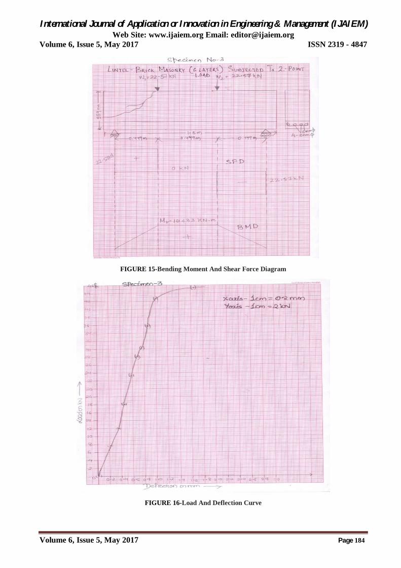
3.6.2 Observation of RCC lintel-Brick Masonry (6 layers)
Table 9- Test Result For Specimen 3 Subjected To Two Point Load
Serial no.
Provingring reading
Corresponding Load in KN
Deflection in Dial Gauge(mm)
Remarks
1 0 0 0 2 27 7.714 0.21 3 42 12 0.36 4 63 18 0.46 5 82 23.43 0.59 6 98 28 0.68 7 108 30.857 0.77 8 125 35.71 0.86 9 150 42.86 0.98 Hair crack 10 165 45.14 1.65 Suddenly fail
with diagonal
International Journal of Application or Innovation in Engineering & Management (IJAIEM) Web Site: www.ijaiem.org Email: [email protected]
Volume 6, Issue 5, May 2017 ISSN 2319 - 4847
Volume 6, Issue 5, May 2017 Page 184
FIGURE 15-Bending Moment And Shear Force Diagram
FIGURE 16-Load And Deflection Curve

International Journal of Application or Innovation in Engineering & Management (IJAIEM) Web Site: www.ijaiem.org Email: [email protected]
Volume 6, Issue 5, May 2017 ISSN 2319 - 4847
Volume 6, Issue 5, May 2017 Page 185
3.6.2.1 (a) Theoretical value of Ultimate Moment Capacity for RCC Lintel and brick masonry (6 layers) (by IS-1456:2000)
As per stress-strain curve maximum strain in compression is 0.0028 mm and the maximum strain in tension is 0.0025, which is nearly equal to each other. So we consider the specimen as balanced section. So, x= D/2 = 559/2= 279.5mm C= 0.5 fck b x = 71.049×10³ N T= Astfy = 138.038×10³ N , which is greater than compression So here steel will not yield. Hence it is an over reinforced section. The concrete fails prior to yielding of steel, so we consider the compression zone. Z= d- x/3 = 415.03mm (lever arm) Mu= 0.5 x b fc z = 29.48×10⁶Nmm 3.6.2.1(b) Experimental value of ultimate moment capacity for RCC lintel and brick masonry(6 layers):
Table 10- Moment Capacity Of Rcc Lintel And Brick Masonry
3.6.2.2 (a) Theoretical value of shear strength for RCC Lintel and brick masonry (6 layers) (by F.K.Kong, “Reinforced Concrete Deep Beams”, Taylor & Francis, New York, 2002)
Here, λ, 0.32 for brick weight b, beam thickness d, active height of the beam Ar, area of a typical web bar intersects the critical diagonal crack x, effective clear sshear span fck, compressive strength of brick masonry
International Journal of Application or Innovation in Engineering & Management (IJAIEM) Web Site: www.ijaiem.org Email: [email protected]
Volume 6, Issue 5, May 2017 ISSN 2319 - 4847
Volume 6, Issue 5, May 2017 Page 186
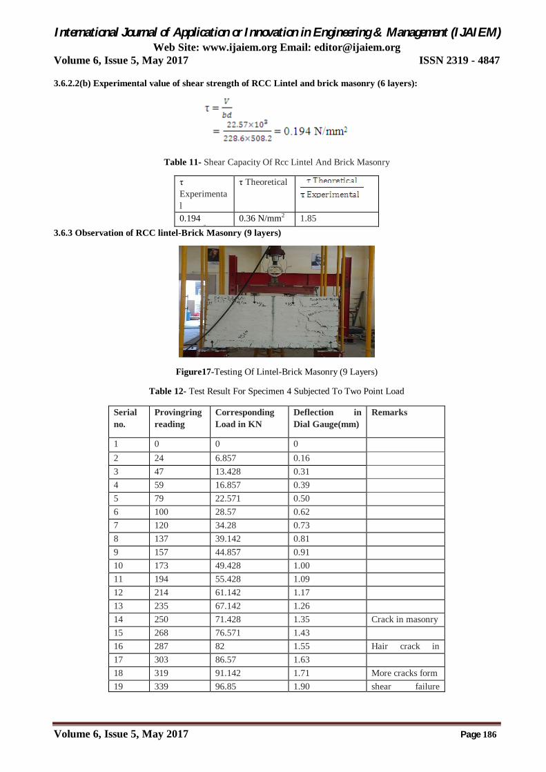
3.6.2.2(b) Experimental value of shear strength of RCC Lintel and brick masonry (6 layers):
Table 11- Shear Capacity Of Rcc Lintel And Brick Masonry
τ Experimental
τ Theoretical
0.194 N/mm2
0.36 N/mm2 1.85 3.6.3 Observation of RCC lintel-Brick Masonry (9 layers)
Figure17-Testing Of Lintel-Brick Masonry (9 Layers)
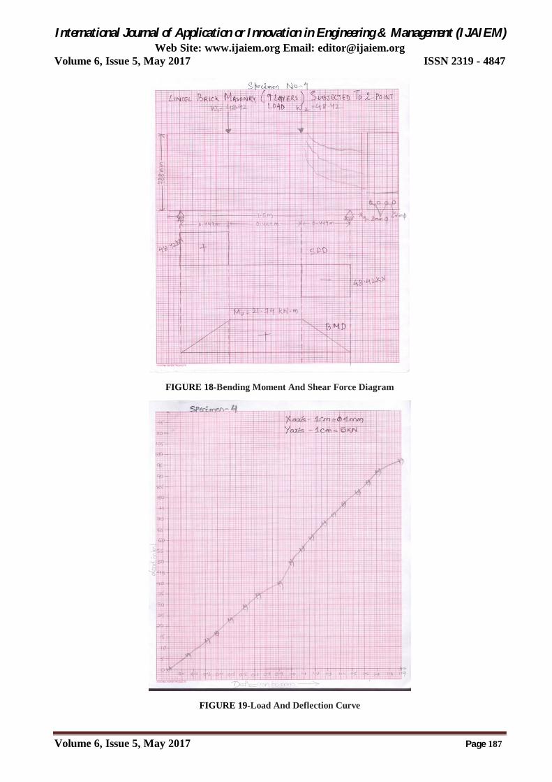
Table 12- Test Result For Specimen 4 Subjected To Two Point Load
Serial no.
Provingring reading
Corresponding Load in KN
Deflection in Dial Gauge(mm)
Remarks
1 0 0 0 2 24 6.857 0.16 3 47 13.428 0.31 4 59 16.857 0.39 5 79 22.571 0.50 6 100 28.57 0.62 7 120 34.28 0.73 8 137 39.142 0.81 9 157 44.857 0.91 10 173 49.428 1.00 11 194 55.428 1.09 12 214 61.142 1.17 13 235 67.142 1.26 14 250 71.428 1.35 Crack in masonry 15 268 76.571 1.43 16 287 82 1.55 Hair crack in
lintel 17 303 86.57 1.63 18 319 91.142 1.71 More cracks form 19 339 96.85 1.90 shear failure
International Journal of Application or Innovation in Engineering & Management (IJAIEM) Web Site: www.ijaiem.org Email: [email protected]
Volume 6, Issue 5, May 2017 ISSN 2319 - 4847
Volume 6, Issue 5, May 2017 Page 187
FIGURE 18-Bending Moment And Shear Force Diagram
FIGURE 19-Load And Deflection Curve

International Journal of Application or Innovation in Engineering & Management (IJAIEM) Web Site: www.ijaiem.org Email: [email protected]
Volume 6, Issue 5, May 2017 ISSN 2319 - 4847
Volume 6, Issue 5, May 2017 Page 188
3.6.3.1(a) Theoretical value of Ultimate Moment Capacity for RCC Lintel and brick masonry (9 layers) (by IS-1456:2000)
As per stress-strain curve maximum strain in compression is 0.0028 mm and the maximum strain in tension is 0.0025, which is nearly equal to each other. So we consider the specimen as balanced section. So, x= D/2 = 788/2= 394mm C= 0.5 fck b x = 100.156×10³ N T= Astfy = 138.038×10³ N , which is greater than compression So here steel will not yield. Hence it is an over reinforced section. The concrete fails prior to yielding of steel, so we consider the compression zone. Z= d- x/3 = 605.86 mm (lever arm) Mu= 0.5 x b fc z = 60.68×10⁶ N mm 3.6.3.1 (b) Experimental value of ultimate moment capacity for RCC lintel and brick masonry(9 layers):
Table 13- Moment Capacity Of Rcc Lintel And Brick Masonry
3.6.3.2 (a) Theoretical value of shear strength for RCC Lintel and brick masonry (9 layers) (by F.K.Kong, “Reinforced Concrete Deep Beams”, Taylor & Francis, New York, 2002)
Here, λ, 0.32 for brick weight b, beam thickness d, active height of the beam Ar, area of a typical web bar intersects the critical diagonal crack x, effective clear sshear span fck, compressive strength of brick masonry
International Journal of Application or Innovation in Engineering & Management (IJAIEM) Web Site: www.ijaiem.org Email: [email protected]
Volume 6, Issue 5, May 2017 ISSN 2319 - 4847
Volume 6, Issue 5, May 2017 Page 189
3.6.3.2 (b) Experimental value of shear strength of RCC Lintel and brick masonry (9 layers):
Table 14- Shear Capacity Of Rcc Lintel And Brick Masonry
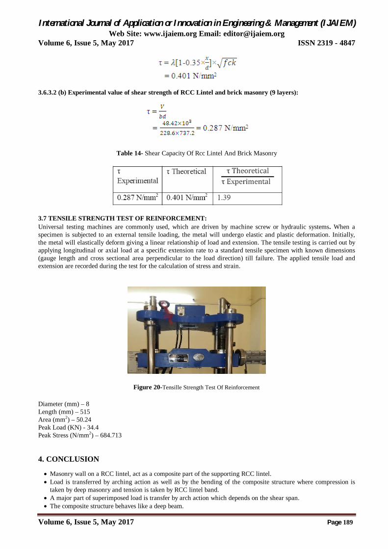
3.7 TENSILE STRENGTH TEST OF REINFORCEMENT: Universal testing machines are commonly used, which are driven by machine screw or hydraulic systems. When a specimen is subjected to an external tensile loading, the metal will undergo elastic and plastic deformation. Initially, the metal will elastically deform giving a linear relationship of load and extension. The tensile testing is carried out by applying longitudinal or axial load at a specific extension rate to a standard tensile specimen with known dimensions (gauge length and cross sectional area perpendicular to the load direction) till failure. The applied tensile load and extension are recorded during the test for the calculation of stress and strain.
Figure 20-Tensille Strength Test Of Reinforcement
Diameter (mm) – 8 Length (mm) – 515 Area (mm2) – 50.24 Peak Load (KN) - 34.4 Peak Stress (N/mm2) – 684.713
4. CONCLUSION
Masonry wall on a RCC lintel, act as a composite part of the supporting RCC lintel. Load is transferred by arching action as well as by the bending of the composite structure where compression is
taken by deep masonry and tension is taken by RCC lintel band. A major part of superimposed load is transfer by arch action which depends on the shear span. The composite structure behaves like a deep beam.

International Journal of Application or Innovation in Engineering & Management (IJAIEM) Web Site: www.ijaiem.org Email: [email protected]
Volume 6, Issue 5, May 2017 ISSN 2319 - 4847
Volume 6, Issue 5, May 2017 Page 190
The structure is supposed to be fail in shear for which horizontal RCC band are provided in between the brick masonry, but in all test we observed that the structure is failed due to joint failure making the horizontal beam ineffective.
It is observed that the flyash brick doesn’t give proper bond as compare to clay brick which is studied by other journal. [9].
REFERENCE
[1] BeallChristine,”Lintel Design and Detailing”,National Concrete Masonry Association,Herndon, 1993. [2] Punmia B.C., Jain Ashok kumar, Jain Arun Kumar, “Building Construction”, LaxmiPulications Pvt. Ltd., 1984. [3] Jaisingh M.P., JaisinghLathika, Jain S K., “Building Research Note-30”,Central Building Research Institute
Roorkee (U.P.),january, 1981 . [4] A.W.Hendry, B.P.Sinha and S.R.Davies, “Design Of Masonry Structures”, Department of Civil Engineering,
University of Edinburgh, UK, ISBN 0-203-37498-3, 1997. [5] U.S. Department of Housing and Urban Development, Office of Policy Development and Research, NAHB
Research Centre , “Lintel Testing for Reduced Shear Reinforcement inInsulating Concrete Form Systems”, Washington DC, May 1998.
[6] Coull Alexander and Wong Yang Chee, “Composite Action between Slabs and Lintel Beams”, Journal of Structural Engineering, 1984.110:575-588.
[7] Md M Sazzad, M MYounus Ali, S M NizamudDoulah “Studies of behaviour of reinforced concrete deep beam under two point loading deep and the effect of shear reinforcement” journal of Structural Engineering, Bangladesh insitude of Technology, Bangladesh, 2002.
[8] Professor F.K.Kong, “Reinforced Concrete Deep Beams”, Taylor & Francis e-Library,New York, 2002. [9] Professor B. Jena, Praveena Rao, “Composite action in RCC and brick masonry”, International jounaral of
scientific and engineering Research, Volume 7, 2016 [10] IS 456:2000, “Indian Standard Plain and Reinforced Concrete- Code of Practice”, Bureau of Indian Standards,
New Delhi. [11] SP 20:1991, “Handbook on masonry construction and design”, Bureau of Indian Standards, New Delhi. [12] SP 16:1980, “Design Aids for Reinforced concrete to IS 456:1978”, Bureau of Indians standards, New Delhi.