commercial kitchen ventilation - sustainable … · fcsi – ckv white paper – 09/22/06 i...
TRANSCRIPT
FCSI White Paper
Commercial Kitchen
Ventilation
“Best Practice” Design and Specification Guidelines
September 2006
FCSI – CKV White Paper – 09/22/06 i
Commercial Kitchen Ventilation “Best Practice” Design & Specification Guidelines
FCSI White Paper
September 22, 2006
Executive Summary The commercial kitchen exhaust ventilation system is just that—a system—and it cannot be designed to its optimum by two professions operating independently of each other. The design model must change if the problems experienced by FCSI members with CKV systems are to be diminished. This white paper takes a global look at all the factors affecting the performance of commercial kitchen ventilation (CKV) systems including design air volumes, cross drafts and location and types of makeup air diffusers. In addition to addressing the design challenge with ventilating display cooking, the white paper provides guidelines for specifying air volumes for all styles of hoods that will work for real world conditions; documents why short cycle/internally compensating hoods don’t work; sheds light on grease capture efficiency ratings, and provides language that the consultant can use to ensure hood performance including procedures for hood performance testing during commissioning. The paper contends that design of exhaust ventilation systems is inherently challenged by a disconnect that typically exists between the foodservice consultant and the mechanical engineer. This communication gap may be attributed, in part, to a general perception by designers, engineers and architects that the function and operation of an exhaust hood is more straightforward than it really is. There is an underlying, but incorrect, supposition that an exhaust hood will function satisfactorily if it is specified in accordance with its UL listed “cubic feet per minute” or “cfm” air flow capacity. This lack of communication or coordination disconnect between the mechanical system and the cooking equipment, whereby the design process does not have an effective feedback loop that identifies the elements of a good system over a poor system, means that the experience from one project is not effectively applied to the next. The recommended elements of an FCSI strategic plan, along with specific best-practice design enhancements, include:
• Deliver the “best practice” guidelines embedded within this white paper through a continuing education track for FCSI members.
• Develop specification templates and examples that will strengthen the exhaust hood system design as well as help guide the mechanical design (with respect to the CKV system).
• Develop specific display cooking ventilation guidelines and specifications, emphasizing the operational limitations and significant exhaust airflow requirements for hoods that are exposed on all four sides.
• Encourage better communication with the mechanical engineer. Although the design of the replacement air system is not, and probably never will be, the responsibility of the foodservice consultant, there must be an increased influence on this side of the design equation.
FCSI – CKV White Paper – 09/22/06 ii
• Review the mechanical drawings. Anticipate the problems that may occur during the design. Strive to influence the mechanical design when potential deficiencies are recognized.
• Utilize hood manufacturers’ software or calculations for selecting an appropriate design value for a given project. Do not base the design exhaust rate on the UL “cfm” listing for a given hood.
• Hold “spec” on the design exhaust “cfm” – it should not be negotiable within a competitive bid and the evaluation of an alternative hood proposal based on a lower UL listed ‘cfm’ value.
• Collaborate on a research project that would investigate the performance of island-canopy hood
configurations under representative display cooking challenges. The scope of this project could extend to the testing of “ventilated ceilings.”
• Eliminate the specification of short-circuit hoods – possibly as far as taking an FCSI official position against this style of hood/makeup air combination.
• Specify performance and secure a guarantee (from the ventilation system manufacturer, mechanical engineer, installing contractor, and others involved) for the performance of the CKV system. Within this context, air balancing of all exhaust and makeup air, and performance testing of CKV systems must be included in all jobs, as these actions are required by most codes, and it “closes the loop” to ensure that all aspects of the system are functioning as designed.
The challenge faced by the foodservice consultant in designing a commercial kitchen with an effective exhaust ventilation system is multifaceted. As this white paper evolved, the authors realized just how complex the problem actually is and that there is no simple solution (ideally desired by FCSI in the commissioning of this study). It will require a comprehensive educational initiative in parallel with developing clear-cut and more demanding specifications for ventilating commercial cooking equipment. The bar can be raised, but only for those FCSI members willing to commit to the professional development aspect and an increased level of effort and/or responsibility within the design of a commercial kitchen ventilation system.

FCSI – CKV White Paper – 09/22/06 iii
Contents Page
1. Commercial Kitchen Ventilation (CKV) – The Design Challenge! 1 2. The Cooking Factor (AKA the Need for Exhaust) 1
3. The Hood Factor – Capture and Containment (C&C) 3 Side Panels 3
Increased Overhang (and Reduced Rear Gap) 4
Hood Geometry 4
Mounting Height 4
Ventilated Ceilings 5
Cross Drafts 5
Makeup Air Factor 5
Short-Circuit (Internal Makeup Air) Supply 6
Four-Way Ceiling Diffusers 6
Ductwork Factor 6
Listed Hoods (…and the Fallacy of Listed “CFM”) 7
Equipment Position Factor 9
Hood Style Factor 9
ASTM Standard F-1704, Test Method for Capture and Containment Performance 10
4. CKV System Effects – Integrating with the HVAC System 11
Impact of Demand Ventilation 11
5. Grease Removal/Filtration/Odor Control 12
6. Strengthening and Incorporating Performance within Hood Specifications 15
7. Field Testing and Commissioning 17
8. Recommendations to FCSI (Meeting the CKV Design Challenge) 18
9. References 20
Exhibit 1: Specification Language to Improve Exhaust Hood Performance 21
Acknowledgements 35
FCSI – CKV White Paper – 09/22/06 1
1. Commercial Kitchen Ventilation (CKV) – The Design Challenge! From the onset of a commercial kitchen project, the design of the exhaust ventilation system is challenged by an inherent disconnect between the foodservice consultant and the mechanical engineer. This communication gap may be attributed, in part, to a general perception by designers, engineers and architects that the function and operation of an exhaust hood is more straightforward than it really is. There is an underlying supposition that the exhaust hood will function satisfactorily if it is specified in accordance with its UL listed “cubic feet per minute” (cfm) air flow capacity. In some cases, this may be far from reality! The fact that the CKV system appears to work just fine for many foodservice projects sustains a “status quo” viewpoint on the part of the consulting team. It is when a ventilation system fails to meet a client’s expectations that the problem is blamed on the exhaust hood specification and/or the mechanical design—and the “finger pointing” begins. Because of the apparent disconnect between the mechanical system and the cooking equipment, the boundary between the work of one profession and that of another often leads to grief for the Client. The typical design process also does not have an effective feedback loop that identifies the elements of a good system over a poor system—so the experience from one project is not effectively applied to the next. This probably explains why short-circuit hoods continue to be specified even though their performance on previous projects was not satisfactory. While foodservice consultants have seemingly succeeded within this design paradigm for many years, the recent popularity of display cooking and the associated application of single-island canopy hoods has intensified the CKV design challenge (as reflected by the candid experiences of FSCI members and their support of this white paper and specification guidelines). The commercial kitchen exhaust ventilation system is just that — a system — and it cannot be designed to its optimum by two different professions operating independently of each other. The design model must change if the problems with CKV systems are to be diminished. Given what we know today about commercial kitchen ventilation systems and all the factors that affect operational performance, one can begin to characterize the CKV design challenge from the standpoint of the foodservice consultant. The goal of this white paper is to explain the parameters that impact CKV system performance and provide a strategic plan and specification template that will help the foodservice consultant realize project success. The specification of the exhaust hood within the design of a commercial kitchen typically falls under the scope of the foodservice consultant whereas the design and specification of the ductwork, exhaust fan and makeup air side of the system falls under the mandate of the mechanical engineer. If the responsibility for specifying the exhaust hood were to be transferred to the mechanical engineer, along with the responsibility for the rest of the building ventilation system, (a solution suggested by some FCSI members), the design “disconnect” would simply shift to the interface between the hood and cooking equipment (the disconnect is currently at the ceiling level between the hood and the ductwork). Since the cooking equipment selection and configuration defines the exhaust requirements, it remains the foundation of the CKV system. As the mechanical engineer has little knowledge of the cooking equipment being installed beneath the hood and its associated “loading” on an exhaust hood, the dilemma in design responsibility will not be resolved so easily. It is the foodservice consultant who inherits the ultimate responsibility for the performance of the kitchen equipment and the success of the foodservice operation. If the exhaust system fails to perform, the foodservice consultant “shares the blame” regardless of whose responsibility it may have been within the design hierarchy. The ability of an exhaust hood to capture and contain (C&C) the effluent (heat, smoke, vapor and flue products) produced by the cooking equipment is a function of much more than the physical attributes of the hood and the specified exhaust capacity. Unfortunately, many of these influencing factors are overlooked in the detailed specifications (e.g., appliance positioning beneath the hood or the delivery path
FCSI – CKV White Paper – 09/22/06 2
of the replacement air). Beneficial design factors, such as overhang, hood height, and side panels or end walls, may be downplayed in terms of their significance and neglected within the specifications. Both the foodservice consultant and the mechanical engineer must learn that there is more to making a hood work effectively than simply specifying its style, size and exhaust rate. Selecting the exhaust hood is only the first step in designing a CKV system, not the last. Add in grease removal and odor control to the matrix and the design challenge intensifies. The foodservice consultant must become involved with all aspects of the system design that affect the hood’s performance, independent of who has official responsibility under the master specification and consulting chain of command. Field performance testing (and potentially a performance guarantee) must become part of the CKV system specification. 2. The Cooking Factor (AKA the Need for Exhaust) Hot air rises! An exhaust fan in the ceiling could easily remove the heat produced by the cooking equipment. But mix in smoke, volatile organic compounds, grease particles and vapor from cooking, water vapor, combustion products, and a means to capture and contain the effluent is needed to avoid health and fire hazards. While an exhaust hood, and the system components downstream, serves these purposes, the key question is always:
“What is the appropriate exhaust rate?” …and the answer always depends on:
(1) the type, energy source and use of the cooking equipment below the hood, (2) the position of this cooking equipment below the hood, (3) the style and geometry of the hood itself, and (4) how the makeup air (conditioned or otherwise) is introduced into the kitchen.
Cooking appliances are categorized by model codes and standards as light, medium, heavy, and extra heavy duty, depending on the strength of the thermal plume (i.e., heat rising off the equipment) and the quantity of grease and smoke produced. Underwriters Laboratories (UL) and some mechanical codes refer to the cooking equipment duty classifications in terms of cooking temperature (i.e., 400°F, 600°F and 700°F, respectively representing the light/medium, heavy and extra-heavy duty equipment). Both the volume and velocity of the thermal plume rising up from the appliance is a factor in determining the exhaust rate. By their nature, these thermal plumes are very turbulent and different cooking processes have different “surge” characteristics. For example, the plume from hamburger cooking is strongest when flipping the burgers. Ovens, compartment steamers and pressure fryers display very little plume until they are opened to remove food product. Open flame, non-thermostatically controlled appliances, such as underfired broilers and open top ranges, exhibit strong steady plumes. Thermostatically controlled appliances, such as griddles and fryers, have weaker plumes that fluctuate in sequence with thermostat cycling (particularly gas-fired equipment). As the plume rises by natural convection, it is captured by the hood canopy and removed by the suction created by the exhaust fan. Air in the proximity of the cooking bank then moves in to replace it. This replacement air, which must originate as outside air, is referred to as makeup air (MUA). Building codes distinguish between cooking processes that create smoke and grease (e.g., frying, griddling, or charbroiling) and those that produce only heat and moisture (e.g., dishwashing and some baking and steaming operations). Cooking that produces smoke and grease requires liquid-tight construction with a built-in fire suppression system (Type I hood), while an operation that produces only heat and moisture requires neither (Type II hood).
FCSI – CKV White Paper – 09/22/06 3
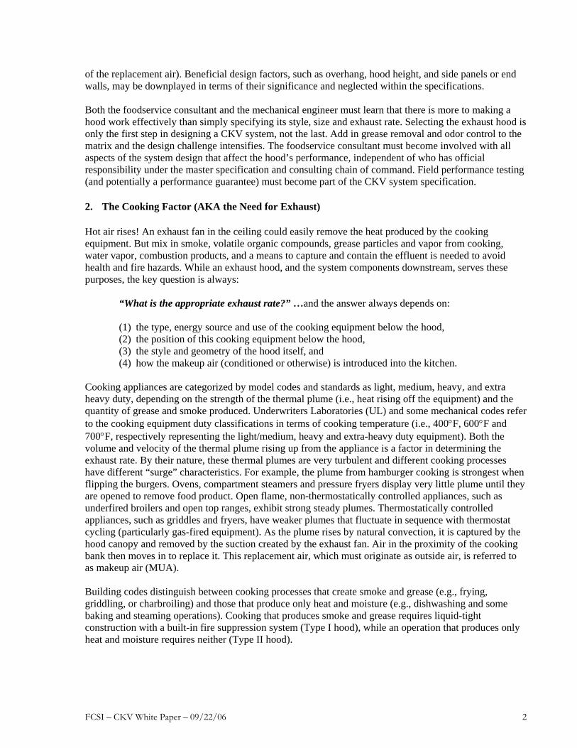
3. The Hood Factor – Capture and Containment (C&C) The design exhaust rate depends on the hood style and construction features, as well as factors mentioned above. Wall-mounted canopy hoods, island (single or double) canopy hoods, and proximity (backshelf, pass-over, or eyebrow) hoods all have different capture areas and are mounted at different heights and horizontal positions relative to the cooking equipment (Figure 1). Generally, for a given line of appliances, a single-island ceiling-hung canopy hood will require significantly more exhaust than a wall-mounted canopy hood, and a wall-mounted canopy hood requires more exhaust than a well-engineered proximity (i.e., eyebrow, backshelf or passover style) hood. The performance of a double-island ceiling-hung canopy hood tends to emulate the performance of two back-to-back wall-canopy hoods, although the lack of a physical barrier between the two hood sections makes this configuration more susceptible to cross drafts. Single-island canopy hoods present the “ultimate” capture and containment challenge in hood applications and are typically the foundation of the problems in display cooking kitchens.
Source: ASHRAE 2003 Applications Handbook, Chapter 31, Kitchen Ventilation
Side Panels
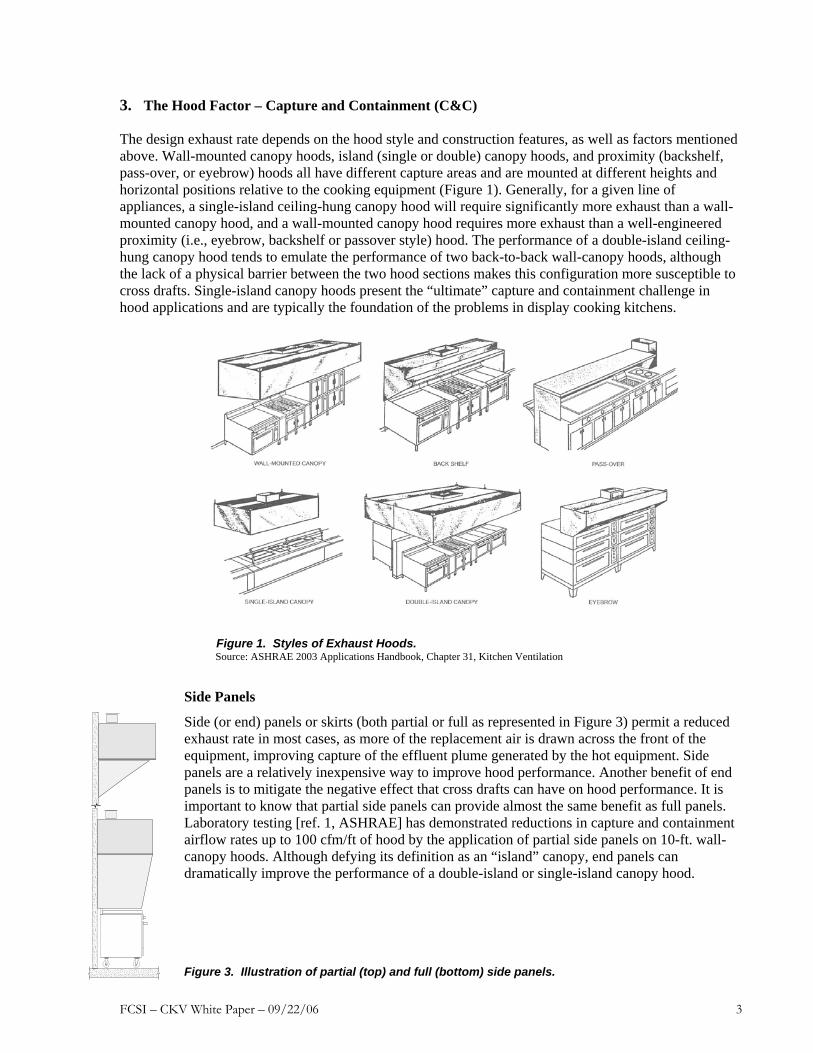
Side (or end) panels or skirts (both partial or full as represented in Figure 3) permit a reduced exhaust rate in most cases, as more of the replacement air is drawn across the front of the equipment, improving capture of the effluent plume generated by the hot equipment. Side panels are a relatively inexpensive way to improve hood performance. Another benefit of end panels is to mitigate the negative effect that cross drafts can have on hood performance. It is important to know that partial side panels can provide almost the same benefit as full panels. Laboratory testing [ref. 1, ASHRAE] has demonstrated reductions in capture and containment airflow rates up to 100 cfm/ft of hood by the application of partial side panels on 10-ft. wall-canopy hoods. Although defying its definition as an “island” canopy, end panels can dramatically improve the performance of a double-island or single-island canopy hood.
Figure 3. Illustration of partial (top) and full (bottom) side panels.
Figure 1. Styles of Exhaust Hoods.
FCSI – CKV White Paper – 09/22/06 4
Increased Overhang (and Reduced Rear Gap)
An increase in hood overhang will improve the capture ability of a canopy hood because of the increased distance between the plume and hood edges. This may be accomplished by pushing the appliances as far back to the wall as practical (not something that is practical with a single-island canopy hood). This also decreases the gap between the rear of the appliance and the back wall, further improving the capture performance of the hood. Larger overhangs are recommended for appliances that create plume surges when doors or lids are opened, such as convection and combination ovens, steam kettles, compartment steamers and pressure fryers. Larger overhangs are recommended for appliances that have larger (deeper) footprints. Specifying a deeper hood (e.g. 5 ft vs. 4 ft) will directly increase overhang, provided appliances remain as far back as possible in the hood, and is an effective solution for the oven or combination-oven and its “door-opening” challenge. Remember that code-required overhangs are minimums, not best practice. Hood Geometry The ability of a hood to capture and contain cooking effluent may be enhanced by adding passive features (e.g., angles, flanges, or geometric flow deflectors) or active features (e.g., low-flow, high-velocity jets) along the edges of the hood or within the hood reservoir. Such design features can improve hood performance over a basic box-style hood with the same nominal dimensions. These edge details help to contain an aggressive thermal plume within the hood reservoir giving more time for this effluent to be removed through the filters. Typically, a large portion of an aggressive plume (rising vertically from the cooking surface) will blow by the filter or inlet slot and circulate within the canopy of the hood and down the front and/or sides of the hood enclosure. If features is incorporated to redirect this downward flowing effluent back towards the filter, the performance of the hood (i.e., its ability to capture and contain at reduced airflows) is improved. This may comprise a simple right angle flange along the front inside edge of the hood. In other cases, a triangular sheet metal detail within the front wall of the hood has been used to achieve the same effect. In one case, a dynamic solution has been to incorporate an active high-velocity, low airflow air jet along the front edge and/or side of the hood canopy to effectively contain the effluent plume, thus providing an incremental performance benefit over the static sheet metal solution. Mounting Height
Hood mounting height (or more specifically the distance from finished floor to front lower edge of an exhaust hood) can impact the ability of the hood to capture cooking effluent. Obviously, the further the hood is from the cooking surface, the easier it is for the cooking effluent to escape the hood footprint (driven by adverse cross drafts) and not be removed from the kitchen. Recent research [ref. 1, ASHRAE] demonstrated that increasing the mounting height of a wall-mounted canopy hood from 6 ft. 6 in. to 7 ft. 6 in. required a moderate increase in exhaust rate (14%) if the heavy-duty appliance challenge was located at the end of the hood. If this heavy-duty challenge was moved to the center of the 10-ft. test hood, the effect of increased hood height was negligible. Based on this cursory research, the authors of this white paper believe that minimizing hood-mounting height remains a justifiable best practice, particularly for island canopy hoods (for which we have no test data). If the performance of a single-island canopy hood is challenged at 6 ft. 6 in., it will be even more challenged at 7 ft 6in. That said, the recent practice of specifying a hood mounting height of 6 ft. 8 in. in response to the Uniform Federal Accessibility Standards (UFAS) that calls out 80 inches (6 ft. 8 in.) for headroom, is not considered (by the authors) to be a significant factor in hood performance. Even a 7 ft. mounting height for a wall-mounted canopy, if combined best practice features such as a deeper hood with end skirts and heavy-duty appliances positioned towards the middle, is not a performance compromise.
FCSI – CKV White Paper – 09/22/06 5
Ventilated Ceilings
Ventilated ceilings are a concept that originated in Europe and was recently introduced in North America. The concept is attractive for the display cooking application, although there is an obvious concern about capture and containment performance, as well as potential grease loading of the ceiling, particularly for heavy-duty appliances such as charbroilers. At this point, there is a need for performance data and objective case-study feedback to the design community. This application is particularly appealing for an island cook line being used at a culinary school theater, or when openness and line-of-sight issues are important.
Cross Drafts Cross drafts often have a detrimental effect on all hood/appliance combinations. Cross-drafts will affect island canopy hoods more than wall-mounted canopy hoods because they have more open area allowing drafts to push or pull effluent from the hood. For example, a pedestal fan used by the kitchen staff for additional cooling can severely degrade hood performance by pushing smoke and heat from the cooking equipment into the kitchen. Delivery doors, service doors, pass-through openings and drive-through windows may be sources of cross drafts due to external and internal air pressure differences. Cross drafts also can be developed when the makeup air system is not working correctly or when it has been improperly designed to start with. Adjustments are frequently made after the initial test and balance by maintenance and servicing personnel. Safety factors are typically applied when determining the designed exhaust rate to compensate for the effect that undesired air movement within the kitchen has on hood performance. However, it may take a very large safety factor to overcome a cross draft problem in an island hood application. Makeup Air Factor The layout of the heating, ventilating, and air-conditioning (HVAC) and makeup air (MUA) supply air outlets or diffusers can affect hood performance. These can be sources that disrupt thermal plumes and hinder C&C. Air that is removed from the kitchen through an exhaust hood must be replaced with an equal volume of outside replacement (makeup) air through one or more of the following pathways:
1. Transfer air (e.g., from the dining room and/or kitchen HVAC unit) 2. Displacement diffusers (floor or wall mounted) 3. Ceiling diffusers with louvers (2-way, 3-way, 4-way) 4. Slot diffusers (ceiling) 5. Ceiling diffusers with perforated face 6. Integrated hood plenum including:
• Short circuit (internal supply) • Air curtain supply (vertical discharge along the lower front of the hood) • Front face supply (horizontal discharge from the front of the hood) • Perforated perimeter supply (vertical discharge along the top front of the hood) • Backwall supply (rear discharge behind the appliances) • Combinations of the above
Introducing makeup air into the kitchen without disrupting the ability of the hood to capture and/or without causing discomfort for the kitchen staff is a huge challenge. Dumping 8,000 cfm of MUA, for example, along the front of a 25-foot cook line does not go as smoothly in practice as it might on a theoretical air balance schedule. Another way to look at this is to never “force” air towards the hood—make the hood do the work and “pull” the air towards itself. Not only can makeup air velocities hamper the ability of the hood to capture and contain cooking effluent, locally supplied makeup air that is too cold or too hot can create an uncomfortable working environment.
FCSI – CKV White Paper – 09/22/06 6
The International Mechanical Code (IMC) requires that “the temperature differential between makeup air and the air in the conditioned space shall not exceed 10ºF. Exceptions include (1) makeup air that is part of the air conditioning system and (2) makeup air that does not decrease the comfort conditions of the occupied space. Obviously, exception number 2 falls into the “gray zone” of interpretation by both the designer and the authority having jurisdiction (AHJ). Short-Circuit (Internal Makeup Air) Supply
The application of short-circuit makeup air hoods continues (unfortunately) to be a controversial topic and deserves dedicated discussion in this white paper. These internal makeup air hoods were developed as a strategy to reduce the amount of conditioned air required by an exhaust system. By introducing a portion of the required makeup air in an untempered condition directly into the exhaust hood reservoir, the net quantity of conditioned air exhausted from the kitchen is reduced (with a corresponding assumption of reduced energy costs). Research [ref. 2 & 3 California Energy Commission] has shown however, that in the cases tested, internal makeup air cannot be introduced at a rate that is more than 15% of the C&C exhaust rate without causing spillage (despite what is shown on the air balance schedule or marketing literature). In fact, the study showed that once the threshold for C&C was exceeded, every additional “cfm” of short-circuit air introduced within the hood reservoir required that the exhaust rate be increased by another “cfm” to sustain capture. When short circuit hoods are operated at higher percentages of internal MUA they fail to capture and contain the cooking effluent, often spilling towards the back of the hood rather than along the front edge of the hood (the dynamic barrier caused by the introduction of the short-circuit air suppresses spillage along the front edge of the hood). Dilution of the thermal plume with the internal MUA can further disguise spillage, but a degraded kitchen environment is confirmation that the hood is not effectively capturing the cooking effluent. If the design exhaust rate is significantly higher than the actual rate required for C&C (i.e., includes a large safety factor), the percentage of short-circuit air can be increased accordingly, creating a condition of apparent value. Simply stated, short-circuit hoods are not recommended under any circumstances! This recommendation is endorsed by leading hood manufacturers, even though they may still include short-circuit hoods in their catalogue and competitively bid a project based on a short-circuit hood spec. In other cases, the local representative may promote the concept in pursuit of a marketing advantage and the consultant’s specification on a project. Four-Way Ceiling Diffusers
This is another performance-degrading practice that deserves special mention. Four-way diffusers located close to kitchen exhaust hoods can have a detrimental affect on hood performance, particularly when the flow through the diffuser approaches its design limit. Air from a diffuser within the vicinity of the hood should not be directed toward the hood. Discharge velocity at the diffuser face should be set at a design value such that the terminal velocity does not exceed 75 fpm at the edge of the hood capture area. It is recommended that only perforated plate ceiling diffusers be used in the vicinity of the hood, and to reduce air velocities from the diffusers for a given volume of makeup air—the more diffusers the better. This strategy tends to oppose standard HVAC system design practice, where the engineer is trying to maximize the velocity through a diffuser in order to better distribute conditioned air throughout the space. This is an example of a “best practice” that must be communicated to the mechanical engineer by the foodservice consultant. It should be one of the items that the foodservice consultant checks when reviewing the mechanical drawings. Plainly put, the slower the supply air movement around the perimeter of the hood – the better the C&C. Ductwork Factor
Another aspect of the design challenge relates to the installation of the exhaust ductwork and the potential to increase the static pressure above the design value. An extra right angle or two that was not on the drawings can add resistance, reducing the exhaust flow at the hood. In many cases, the air balance

FCSI – CKV White Paper – 09/22/06 7
contractor can correct a deficit in airflow at the expense of increased fan energy consumption. But in other cases, there may not be enough fan horsepower to accommodate the increase in fan speed needed to pull more air through the hood. And in other cases, the air balance may not be conducted with sufficient integrity to identify that a hood is operating below its design flow rate. The scope of discussion on ductwork could expand quickly to include topics such as pressure testing for liquid tightness, impact of duct velocities, clearance to combustible regulations, or the benefits of pre-fabrication. However, this section in the white paper is limited to the direct impact that ductwork could have on hood capture performance. Listed Hoods (…and the Fallacy of the “CFM” listing) Building and/or health codes typically provide basic construction and materials requirements for exhaust hoods, as well as prescriptive exhaust rates based on appliance duty and the length of the hood (cfm per linear ft.) or the open face area of the hood (cfm per ft2). Codes usually recognize exceptions for hoods that have been tested against a recognized standard, such as UL Standard 710, Exhaust hoods for commercial cooking equipment [ref. 4, Underwriters Laboratories]. Part of this UL Standard is a “cooking smoke and flare up” test. This test is essentially a capture and containment (C&C) test where “no evidence of smoke or flame escaping outside the exhaust hood” must be observed. Hoods bearing a recognized laboratory mark are called listed hoods, while those constructed to the prescriptive requirements of the building code are called unlisted hoods. Generally, a listed hood can be operated at a lower exhaust rate than an unlisted hood of comparable style and size over the same cook line. However, the design exhaust rate should be higher than the listed minimum “cfm” to incorporate some level of safety factor. UL clearly states that under the application of UL 710 “air flow rates are established under draft free laboratory conditions with the appliance cooking surface temperatures as noted. Greater exhaust and/or lesser supply air flow rates may be required for each specific installation to obtain complete vapor and smoke removal.” However, this caveat gets lost as the hood manufacturers vie for a consultant’s specification based on their agency listed ‘cfm” for a given hood type and application. Note that the listing agency does not have to be UL, even though the listing must be in accordance with the UL 710 Standard (several hood manufacturers recently have used ETL as a listing agency). Unfortunately there is a widespread belief within the design community (which tends to be propagated by the sales side of the CKV industry) that the listed minimum “cfm” value is an appropriate design exhaust rate. In many cases, this can be far from the reality. When application engineers from hood manufacturers are queried (outside the context of a competitive bidding situation) for an exhaust airflow recommendation, they will consistently suggest air flows that exceed the listed “cfm” for the hood application under consideration. But when push-comes-to-shove in the competitive arena, the listed “cfm” continues to be endorsed as a basis for design and hood selection. The ASHRAE Handbook Chapter on Kitchen Ventilation [ref. 5, ASHRAE] provides a table of typical design rates for “listed” hoods (noted as Table 1 in this white paper). This table was developed with input from the major hood manufacturers in an effort to provide a designer with a sense of realistic airflow rates for a given hood application. Unfortunately, the information in this table is not widely understood or used by foodservice consultants. Note that the upper end of the range for each hood type and appliance duty is well above typical “listed” minimum airflows for each hood type. And it is the upper end of these ranges that provides a safe starting point for the design of an exhaust ventilation system. Unless valid test data for a similar cook line and appliance configuration (not the listed values) can be provided, or a guarantee secured from the hood supplier for a reduced exhaust rate, the consultant should hold to design values toward the upper end of the ranges in Table 1. The range reflected in this table is due to the fact that there is a large variation in the cooking effluent challenge for different foodservice operations, even for the same “duty” category of appliances. It is also due to the fact that listed hoods are not created equal—some hoods work better than others. This is why it is important to select the design ventilation rate using hood manufacturers’ software tools or hood sizing formulas, rather than their “listing” values.
FCSI – CKV White Paper – 09/22/06 8
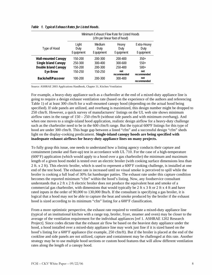
Table 1. Typical Exhaust Rates for Listed Hoods.
Minimum Exhaust Flow Rate for Listed Hoods (cfm per linear foot of hood)
Type of Hood Light Duty
Equipment
Medium Duty
Equipment
Heavy Duty
Equipment
Extra-Heavy Duty
Equipment
Wall-mounted Canopy 150-200 200-300 200-400 350+ Single Island Canopy 250-300 300-400 300-600 550+ Double Island Canopy 150-200 200-300 250-400 500+
Eye Brow 150-250 150-250 not recommended
not recommended
Backshelf/Passover 100-200 200-300 300-400 not recommended
Source: ASHRAE 2003 Applications Handbook, Chapter 31, Kitchen Ventilation For example, a heavy-duty appliance such as a charbroiler at the end of a mixed-duty appliance line is going to require a design exhaust ventilation rate (based on the experience of the authors and referencing Table 1) of at least 300 cfm/ft for a wall-mounted canopy hood (depending on the actual hood being specified). If side panels are utilized, and overhang is maximized, this design number might be dropped to 250 cfm/ft. However, a quick survey of manufacturers’ listings on the UL web site shows minimum airflow rates in the range of 150 – 250 cfm/ft (without side panels and with minimum overhang). And when one moves to a single-island hood application, realistic design airflow for a heavy-duty challenge such as the charbroiler need to be in the 600 cfm/ft range. But the typical 600ºF listings for this type of hood are under 300 cfm/ft. This huge gap between a listed “cfm” and a successful design “cfm” sheds light on the display-cooking predicament. Single-island canopy hoods are being specified with inadequate exhaust airflows for heavy-duty appliance lines on many projects. To fully grasp this issue, one needs to understand how a listing agency conducts their capture and containment (smoke and flare-up) test in accordance with UL 710. For the case of a high-temperature (600°F) application (which would apply to a hood over a gas charbroiler) the minimum and maximum length of a given hood model is tested over an electric broiler (with cooking surface dimensions less than 2 ft. x 2 ft). This electric broiler, which is used to represent a 600°F cooking challenge, is installed at one end of the test hood. The exhaust rate is increased until no visual smoke is perceived to spill while the broiler is cooking a full load of 30% fat hamburger patties. The exhaust rate under this capture condition becomes the reported minimum “cfm” within the hood’s listing. Now, any foodservice consultant understands that a 2 ft x 2 ft electric broiler does not produce the equivalent heat and smoke of a commercial gas charbroiler, with dimensions that would typically be 2 ft x 3 ft or 2 ft x 4 ft and have rated inputs in the order of 90,000 to 130,000 Btu/h. If the consultant is specifying a gas broiler, it is logical that a hood may not be able to capture the heat and smoke produced by the broiler if the exhaust hood is sized according to its minimum “cfm” listing for a 600°F classification. From a more optimistic perspective, the exhaust rate required to ventilate a mixed-duty appliance line (typical of an institutional kitchen with a range top, broiler, fryer, steamer and oven) may be closer to the average of the ventilation requirement for the individual appliances [ref 1. ASHRAE 1202 Research Project]. Since codes dictate that the exhaust air flow be based on the heaviest duty appliance under the hood, a hood installed over a mixed-duty appliance line may work just fine if it is sized based on the hood’s listing for a 600°F appliance (for example, 250 cfm/ft). But if the broiler is placed at the end of the cookline and side panels are not utilized, capture and containment may be challenged at this rate. Another strategy may be to use multiple hood sections or custom hood features that will allow different ventilation rates along the length of a canopy hood.
FCSI – CKV White Paper – 09/22/06 9
Equipment Position Factor
The minimum capture and containment rate can vary significantly based on the position of equipment under the hood. For example, a heavy-duty appliance at the end of a hood is more prone to spillage than the same appliance located in the middle of the hood. Front to back positioning of equipment (e.g., overhang) can dramatically affect the exhaust rate needed [ref. 1 & 2, ASHRAE and CEC research]. In almost all cases, the measured exhaust rates from reported research were significantly higher than the typical listed “cfm” for the style of hood being tested. Design values for exhaust capacity (of the specified hood) need to be derived from the experience of the foodservice consultant and/or input from the hood manufacturer’s engineering application group. With reference to the recommended values in Table 1, the design airflow rate should be selected from the upper end of each range, unless the designer has more specific performance information or a guarantee that the hood will perform at the lower airflows. Once specified, the exhaust “cfm” should not be negotiable on a project, despite the performance claims (based on UL Listings) of an alternative supplier. Hood Style Factor
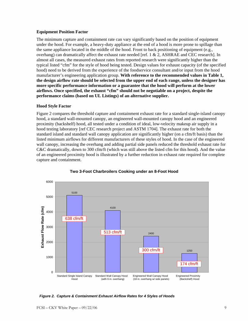
Figure 2 compares the threshold capture and containment exhaust rate for a standard single-island canopy hood, a standard wall-mounted canopy, an engineered wall-mounted canopy hood and an engineered proximity (backshelf) hood, all tested under a condition of ideal, low-velocity makeup air supply in a hood testing laboratory [ref CEC research project and ASTM 1704]. The exhaust rate for both the standard island and standard wall canopy application are significantly higher (on a cfm/ft basis) than the listed minimum airflows for different manufacturers of these styles of hood. In the case of the engineered wall canopy, increasing the overhang and adding partial side panels reduced the threshold exhaust rate for C&C dramatically, down to 300 cfm/ft (which was still above the listed cfm for this hood). And the value of an engineered proximity hood is illustrated by a further reduction in exhaust rate required for complete capture and containment.
Figure 2. Capture & Containment Exhaust Airflow Rates for 4 Styles of Hoods
Two 3-Foot Charbroilers Cooking under an 8-Foot Hood
5100
4100
2400
1250
0
1000
2000
3000
4000
5000
6000
Standard Single Island CanopyHood
Standard Wall Canopy Hood (with 6 in. overhang)
Engineered Wall Canopy Hood (18 in. overhang w/ side panels)
Engineered Proximity (Backshelf) Hood
Exha
ust F
low
Rat
e (c
fm)
638 cfm/ft
513 cfm/ft
300 cfm/ft
174 cfm/ft
FCSI – CKV White Paper – 09/22/06 10
But overhang (or appliance setback) is not a parameter that can be “played with” in a single-island canopy installation to improve its performance. In fact, when makeup air introduction schemes create havoc with the capture of the thermal plume from heavy-duty equipment such as a charbroiler, an exhaust rate as high as 600 cfm/ft (measured along one side of the canopy hood) may be far from adequate for a single-island canopy. An exhaust rate of 600 cfm/ft is well above the standard specification of foodservice consultants and/or manufacturer recommendation based on the hood’s listing for this application. This is the foundation for the failure of a display-cooking hood to perform as expected. Unfortunately, other than this study, there has been very little public-domain performance testing of island canopy hoods and the factors that affect performance. FCSI would be welcomed a co-sponsor of research to document the performance of various configurations of island canopy hoods over representative cooking appliance configurations. Besides adding the FCSI name to this research, it would aid members in serving their clients more professionally. ASTM Standard F-1704, Test Method for Capture and Containment Performance Threshold exhaust rates for a specific hood and appliance configuration may be determined by laboratory testing under the specifications of ASTM F 1704-05, Standard Test Method for Capture and Containment Performance of Commercial Kitchen Exhaust Ventilation Systems. This standard test method was developed [ref. 6, ASTM] to provide a more reliable measure of a hood’s ability to capture and contain the effluent produced by a defined cooking challenge. The phrase "hood capture and containment" is defined in ASTM-1704 as "the ability of the hood to capture and contain grease-laden cooking vapors, convective heat and other products of cooking processes”. Hood capture refers to the products getting into the hood reservoir, while containment refers to these products staying in the hood reservoir and not spilling out into the adjacent space. The phrase "minimum capture and containment" is defined as "the conditions of hood operation at which the exhaust flow rate is just sufficient to capture and contain the products generated by the appliance in idle or heavy-load cooking conditions, or at any intermediate prescribed load condition”. During a C&C test with the cooking appliances in full production, the exhaust rate is reduced until spillage of the plume is observed. The exhaust rate is then increased in fine increments until a condition of C&C is established. Similar in concept to the listed “cfm” derived from UL 710, the threshold of C&C for an ASTM 1704 test is established under ideal laboratory conditions and is only a reference point for specifying the exhaust flow of an exhaust hood. Note that the threshold exhaust rates shown in Figure 2 were established using the ASTM 1704 protocol. CKV System Effects – Integrating with the HVAC System Integration of the CKV system with the HVAC system further complicates the design challenge and often the ability of the CKV system to perform to expectations. The HVAC design details can make or break the CKV system performance because makeup air delivery to the exhaust hood can influence capture and containment. The key to avoiding performance problems is communication between the foodservice consultant and the mechanical engineer. The food service consultant needs to influence the design and participate in the review of mechanical drawings for the kitchen. Most hood manufacturers would be happy to assist the consultant in this coordinated effort and be the ‘go-between’ to speak both languages. The replacement air required for kitchen ventilation systems is always 100% of the exhaust airflow. A common design practice is to supply about 80% of replacement air using an independent makeup air unit with the remaining 20% supplied by conditioned outside air from HVAC units serving the kitchen or transfer air from adjacent spaces. CKV Lab research [ref CEC PIER study] demonstrated that supplying more than 60% of the replacement air requirement within the vicinity of the hood could challenge the hood’s ability to capture and contain, unless the exhaust rate was increased. In many climates replacement air from an independent makeup air unit is not conditioned, which may create uncomfortable conditions in the kitchen. Conventional design practice does not take full advantage of the relatively high rate of
FCSI – CKV White Paper – 09/22/06 11
occupancy ventilation air that is introduced into the dining room or other areas of the building adjacent to the kitchen that can be transferred as a contribution to the makeup requirement. Due to high design occupancies in dining rooms there is an opportunity to use occupancy ventilation air as replacement air, reducing or eliminating the fraction of replacement air from the independent makeup air unit. Since occupancy ventilation air is conditioned in most cases, transferring it to the kitchen for use as replacement air can improve comfort conditions in the kitchen. Although this strategy usually is permitted by code (note that transferring air from smoking areas of a dining room or bar may not be an acceptable option) it goes against general design practice where the mechanical engineer is comfortable specifying a dedicated makeup air supply that will replace 80 to 90% of the air being exhausted. This is another reason for the consultant to communicate with the mechanical engineer. Impact of Demand Ventilation
The concept of demand-controlled ventilation is attractive within the design of commercial kitchens. While this technology currently is lead by one manufacturer, it is anticipated that other strategies of variable speed control will emerge and that its specification in commercial kitchens will become mainstream. A primary component of demand-ventilation control is a variable frequency drive (VFD) on both the exhaust and makeup air fans. This facilitates balancing the system and allows the designer to incorporate a larger “cfm” safety factor within the exhaust hoods specification without an ongoing penalty to the foodservice operator. This safety factor can be “taken out” of the system during commissioning, but it is always there if needed (a good choice for an island canopy hood as replacing the exhaust fan is not the preferred option when the hood fails to perform). Sometimes concern may be expressed that an exhaust fan and motor assembly is not compatible with a VFD. Although possibly a problem in a retrofit, this is not a problem in a new design as it is easy for the mechanical engineer to specify a VFD compatible fan package. The economic return on a demand-ventilation control (DVC) package generally increases with the size of the project (i.e., larger hoods). FCSI consultants are often involved with institutional kitchen designs where the design exhaust rate is significant and the use of cooking equipment is very meal-period specific (e.g., hotels, hospitals, schools). This provides an attractive opportunity for demand ventilation control. The subject of demand ventilation could become a dedicated best-practice module within the scope of expanding educational resources for FCSI members. 4. Grease Removal/Filtration/Odor Control The subject of grease removal and odor control becomes an essay unto itself within this CKV white paper (and associated breakout session in future educational forums). From the perspective of the FCSI member, the effluent control challenge associated with wood-fired equipment may rival the display cooking challenge. When it comes to specifying a control package to mitigate the emissions from wood-fired equipment, everyone steps forward with their preferred technology package. But when the system fails to meet client expectations and the complaints roll in, the finger-pointing routine commences and any implied performance guarantees evaporate. Primary grease removal occurs within the hood itself, including baffle filters, cartridge style filters, and built in grease extractors. Adding to this list of primary filter devices are a number of secondary stages that include water mist, mesh filters and compact-bed filtration media. And downstream the primary and/or secondary devices, one may specify technologies or combination of technologies such as ultraviolet light (UV), electrostatic precipitators (ESP), catalysts, water-based scrubbers, and high efficiency HEPA filters. The final component of a complete (and hopefully effective) emission control package could include an odor control module comprising activated charcoal/potassium permanganate blend or an odor-masking chemical. But this comprehensive emission control package comes with a significant price tag – both in first cost and maintenance.
FCSI – CKV White Paper – 09/22/06 12
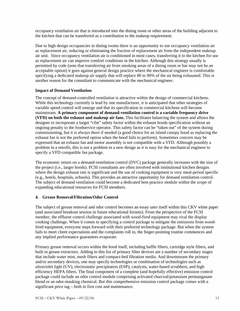
Grease production from cooking equipment and its control need to be systematically dissected to understand the challenge facing the foodservice consultant. Definitions need to be put forward that may or may not be consistent with a consultant’s understanding of grease emissions and the ability of a filtration system to remove grease from the system. ASHRAE previously funded a research project [ref ASHRAE RP 745] that provided new insights into the characteristics of the grease being produced by cooking processes. Figure 3 presents a summary of the grease emissions that were quantified for different appliances and food product. The data illustrate why a grease filtration system may fall short of the manufacturer’s claim and/or the designer’s expectation. An immediate observation is that the quantity of grease released into the air stream varies significantly from one appliance to the other. An underfired gas broiler may introduce 50 pounds of grease into an air stream for every 1000 pounds of hamburger patties cooked; while a griddle will produce only 15 pounds of air-borne grease per 1000 lb. of food cooked. And somewhat counterintuitive, a deep-fat fryer was shown to introduce very little grease into the exhaust steam. What one sees in the aggressive plume generated by a fryer is condensed water vapor from the dehydrating food product. The air quality experts refer to the solid droplets of grease in the air stream as particulate matter (PM) while grease that has not yet condensed into small particles is denoted as vapor. This vapor component may often be described as condensable particulate matter (condensable PM) because it will condense into ultra fine (sub micron) grease droplets when the air stream is cooled to ambient temperatures (e.g., less than 60°F). It is important to recognize that “condensable” grease vapor cannot be extracted by mechanical filtration until it has condensed into actual particles. In all instances, the grease vapor (i.e., a gas) sails merrily through the baffle filter and into the ductwork. This explains why there can be a build up of grease around an exhaust fan on the roof of a restaurant in a cold climate zone, while the exhaust fan on a restaurant in a southern climate is grease free. The grease breakdown for a gas broiler cooking burgers shows that less than 50% of the grease introduced into the air stream exists as particles that are larger than 2.5 microns (micrometers) in diameter. Unfortunately, particle sizes that are 2.5 microns or smaller are very difficult, if not impossible, to remove by the centrifugal forces imposed on the air stream by a baffle filter. Figure 4 illustrates the efficiency of grease removal for a high-efficiency baffle filter with respect to the different grease particle sizes. Note that below 2.5 microns in diameter, the grease extraction efficiency of the baffle filter approaches zero. In other words, the best baffle filter on the market that is installed in an exhaust hood is not going to be able to remove 50% of the grease in the thermal plume created by a charbroiler. The grease control challenge becomes clear. It’s no wonder fire protection and duct cleaning remain crucial issues in the exhaust hood business.

FCSI – CKV White Paper – 09/22/06 13
A manufacturer’s claim that their filter can remove 95% of the grease is a dramatic overstatement of reality. Although these removable baffle filters are listed in accordance with UL 1046, Standard for Grease Filters for Exhaust Ducts, this UL Standard does not measure or rate the grease removal efficiency of a grease filter or cartridge. Thus, exaggerated grease filter efficiency claims continue to propagate within the sales literature and undoubtedly confuse the foodservice consultant.
In order to remove the small grease particles and vapor from the air steam, we must utilize more sophisticated technologies downstream of the basic baffle filter. In support of the variety of secondary grease removal strategies and devices, the industry has ratified a new ASTM test method [ref. 7, ASTM 2519] for quantifying the efficiency of grease extraction with respect to particle size (see example in Figure 4). However, testing and publication of efficiency data for grease removal devices is in its infancy, so consultants must rely on their experience and intuition for a few more years. Eventually foodservice consultants will be able to specify a grease filter efficiency in accordance with ASTM F-2519 [ref ASTM] as performance data is made available by the manufacturers. The authors of this white paper believe, that in the relatively near future, it will be possible to develop a FCSI best-practice guideline for specifying grease removal devices and systems.
Figure 3. Total grease emissions by cooking process.
FCSI – CKV White Paper – 09/22/06 14
Perspective on UV Technology
Ultraviolet light (UV) as a grease control strategy is being offered by at least four hood manufacturers in the U.S. There still remains, however, very limited published data on the performance of this technology when it is applied to commercial kitchen ventilation systems. That said, the authors believe the technology has a legitimate role in mitigating grease loading in ductwork and reducing its release into the environment. But it is not a panacea for total grease and odor control. Most manufacturers acknowledge that a UV light system is not going to completely remove smoke or odors. The industry needs a test protocol for evaluating the performance of UV systems. Until such time, UV technology, along with competing (or complementary) technologies such as electrostatic precipitators (ESP), catalysts, water-based scrubbers, high efficiency HEPA filters, and activated charcoal/potassium permanganate modules must be critically evaluated by FCSI members as they gain experience from projects where they have specified these emerging technologies.
Particle Extraction Efficiency by Aerodynamic Size(Sample)
0.00
20.00
40.00
60.00
80.00
100.00
120.00
2.28 2.84 3.28 3.78 4.37 5.05 5.83 6.73 7.74 8.97
Particle Diameter (micron)
Extra
ctio
n Ef
ficie
ncy
Figure 4. Fractional efficiency of a high-efficiency baffle filter (Reference CE-CERT).

FCSI – CKV White Paper – 09/22/06 15
5. Strengthening Language and Incorporating Performance within Hood Specifications Construction Specifications Institute (CSI) publishes MasterFormat™, which is a list of standardized numbers and titles for organizing construction bidding and contract requirements, specifications, drawing notes, cost data, and building operations by work results. Most architects and engineers use this system to develop project specifications. The 1995 edition of MasterFormat included commercial kitchen hoods in Section 15870, under the design supervision of the mechanical engineer. However, many projects in the past (and present) included commercial kitchen exhaust hoods in Division 11, Equipment, under Section 11400, Foodservice Equipment. The foodservice consultant included the exhaust hoods in the equipment schedule and described other requirements under the Products part of the Section and thus had direct control over specifying the hoods. If compensating hoods (i.e., hoods with integrated makeup air supply) were required, then the consultant also had some control over how makeup air was introduced. However, diffuser and grille layout, as well as makeup air tempering were in Division 15, Mechanical, and thus under the design supervision of the mechanical engineer. In general, from the authors’ past experience, the communication between the foodservice designer and the mechanical engineer was limited to expected exhaust rates. This level of communication has proved insufficient. MasterFormat was expanded in 2004 from 16 divisions to 50 divisions due to the increasing complexity of building systems and products.1 The most significant change from the perspective of the foodservice consultant and the mechanical engineer is that commercial kitchen exhaust hoods are now included in Division 23, the new home for mechanical system specifications. Under the new format, commercial kitchen hood specifications are under Division 23, Section 38, Ventilation Hoods. Commercial kitchen hoods are under Paragraph 13 (Level 3), and the specifics for listed hoods are under Subparagraph 13 and for unlisted hoods (called Standard Commercial Kitchen Hoods in MasterFormat) are under Subparagraph 16. Table 2 shows these numbers and titles. Since it is our view that coordination in the past and present is typically poor, more effort will be needed by the foodservice consultant to assure that commercial kitchen ventilation systems (exhaust hoods and makeup air sources) are designed, specified, installed, and commissioned properly. If the exhaust hood specification is in Division 23, some may view this as taking the responsibility (and, incidentally, the liability) for hood performance away from the foodservice consultant. But in the short term, consultants are likely to get the call about the smoke filled kitchen. Regardless of whether specifications are structured using the 1995 or 2004 MasterFormat, the foodservice consultant should take steps to assure that better performance is “built-in”. These steps may include:
• Increase communications with the mechanical designer about diffuser layout, hood selection criteria, and hood accessories such as side panels.
• Insist that language be included in the hood specification that all “or equal” submissions comply with the design exhaust rate and design static pressure.
• As the concept of performance specifications matures within the CKV industry [hopefully in the short term], the consultant will be able to require that the hood manufacturer provide documentation for exhaust hood performance testing per ASTM Standard F 1704-05 [ref ASTM].
• Similarly, as more manufacturers apply standardized test methods to their grease filter technologies [probably in a longer term], the consultant will be able to require that hood or
1 In addition to expanding the number of general divisions, MasterFormat 2004 Edition adopted a six-digit numbering system in
place of the familiar five-digit system that has been used in MasterFormat since the 1978 edition. This increases the flexibility of
system while maintaining an ordered hierarchy.
FCSI – CKV White Paper – 09/22/06 16
exhaust filter suppliers provide documentation of exhaust filter grease removal efficiency performance per ASTM Standard F 2519-05 [ref ASTM].
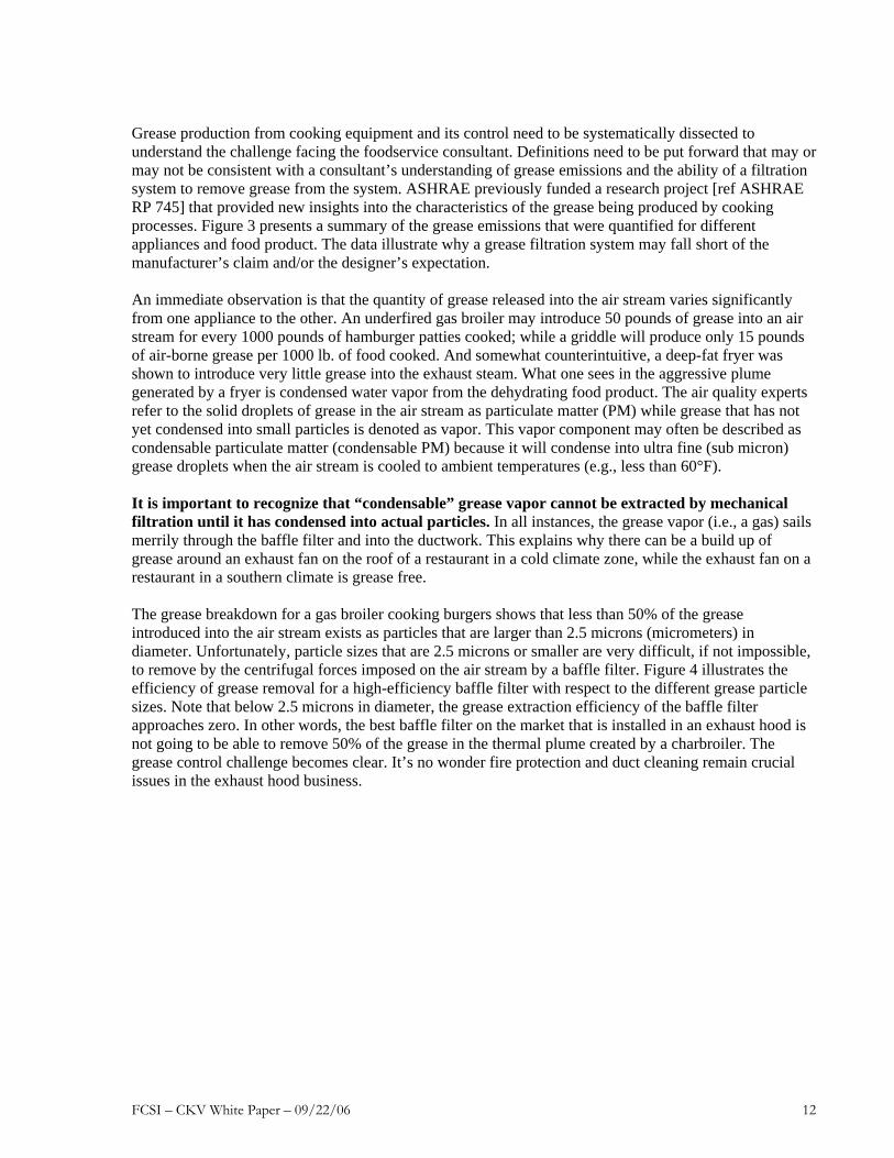
Table 2. MasterFormat 2004 Edition Titles and Numbers for Foodservice Equipment, CKV and HVAC Systems Section Number Section Title
11 00 00 EQUIPMENT 11 01 00 Operation and Maintenance of Equipment11 01 40 Operation and Maintenance of Foodservice Equipment 11 06 40 Schedules for Foodservice Equipment11 06 40.13 Foodservice Equipment Schedule11 40 00 FOODSERVICE EQUIPMENT 11 44 00 Food Cooking Equipment11 44 13 Commercial Ranges11 44 16 Commercial Ovens11 48 00 Cleaning and Disposal Equipment11 48 13 Commercial Dishwashers 23 00 00 Heating, Ventilating, and Air Conditioning 23 37 00 Air Outlets and Inlets23 37 13 Diffusers, Registers, and G rilles23 38 00 Ventilation Hoods23 38 13 Commercial-Kitchen Hoods23 38 13.13 Listed Commercial-Kitchen Hoods23 38 13.16 Standard Commercial-Kitchen Hoods 23 74 00 Packaged Outdoor HVAC Equipment23 74 23 Packaged, Outdoor, Heating-Only Makeup-Air Units23 74 23.13 Packaged, Direct-Fired, Outdoor, Heating-Only Makeup-Air Units 23 74 23.16 Packaged, Indirect-Fired, Outdoor, Heating-Only Makeup-Air Units 23 74 33 Packaged, Outdoor, Heating and Cooling Makeup Air-Conditioners 23 75 00 Custom-Packaged Outdoor HVAC Equipment23 75 23 Custom-Packaged, Outdoor, Heating and Ventilating Makeup-Air Units23 75 33 Custom-Packaged, Outdoor, Heating and Cooling Makeup Air-Conditioners 23 76 00 Evaporative Air-Cooling Equipment23 76 13 Direct Evaporative Air Coolers23 76 16 Indirect Evaporative Air Coolers23 76 19 Combined Direct and Indirect Evaporative Air Coolers
FCSI – CKV White Paper – 09/22/06 17
Field Testing and Commissioning
A performance evaluation (field test) and the commissioning of the CKV system needs to be specified within the design. The foodservice consultant must communicate this requirement to the mechanical engineer, referencing requirements in the IMC. The 2006 Edition of the International Mechanical Code (IMC) requires that a performance test be conducted on the exhaust and makeup air system. This performance test is specified as follows:
507.16 Performance Test. A performance test shall be conducted upon completion and before final approval of the installation of a ventilation system serving commercial cooking appliances. The test shall verify the rate of exhaust airflow required by Section 507.13, makeup airflow required by Section 508, and proper operation as specified in this chapter. The permit holder shall furnish the necessary test equipment and devices required to perform the tests.
507.16.1 Capture and containment test. The permit holder shall verify capture and
containment performance of the exhaust system. This field test shall be conducted with all appliances under the hood at operating temperature, with all sources of outdoor air providing makeup air for the hood operating and with all sources of recirculated air providing conditioning for the space in which the hood is located and operating. Capture and containment shall be verified visually by observing smoke or steam produced by actual or simulated cooking, such as with smoke candles, smoke puffers, etc.
Note: The use of typical smoke “bombs” is not recommended because these devices usually provide a great deal of smoke from a point source, which is not representative of most cooking processes.
FCSI – CKV White Paper – 09/22/06 18
6. Recommendations (Meeting the CKV Design Challenge) The challenge faced by the foodservice consultant in designing a commercial kitchen with an effective exhaust ventilation system is multifaceted. As this white paper evolved, the authors realized just how complex the problem actually is and how there is no straightforward solution (ideally desired by FCSI in the commissioning of this study). No silver bullet on this one! It will require a comprehensive educational initiative in parallel with developing clear-cut and more demanding specifications for ventilating commercial cooking equipment. The bar can be raised, but only for those FCSI members willing to commit to the professional development aspect and an increased level of effort and/or responsibility within the design of a commercial kitchen ventilation system. The recommended elements of an FCSI strategic plan along with specific best-practice design enhancements are summarized below:
• Deliver this “best practice” guideline (and future enhancements) through a continuing education track for FCSI members. It is imperative that foodservice consultants develop an understanding of the issues discussed in the white paper (and factors affecting the ability of an exhaust hood to function as anticipated). The foodservice consultant needs to commit to strengthening the specifications that will help secure an effective CKV system design.
• Develop specification templates and examples that will strengthen the exhaust hood system design as well as help guide the mechanical design (with respect to the exhaust system).
• Develop specific display cooking ventilation guidelines and specifications, emphasizing the limitations and large exhaust airflows required for hoods that are exposed on all four sides.
• Encourage better communication with the mechanical engineer. This is not going to happen automatically, given the current A&E design hierarchy. The foodservice consultant may need to take the initiative, which at a minimum will involve reviewing the mechanical design before the project goes out to bid. The focus of this review should be on how the mechanical engineer has chosen to deliver the makeup air into the kitchen space and the types of diffusers specified. The specified hood manufacturer can often be the “bridge” between the two professions.
• Review the mechanical drawings. Anticipate the problems that may occur during the design. Strive to influence the mechanical design when apparent problems are recognized. Although the design of the replacement air system is not, and probably never will be, the responsibility of the foodservice consultant, there must be an increased influence on this side of the equation (or at least shared responsibility for system performance). The concept of the foodservice consultant compiling a preliminary air balance schedule for the CKV system should be explored.
• The food service consultant should consider specifying (or at least recommending) the local makeup air distribution strategy and amount of air supplied (relative to the amount of air being exhausted). This is done when a compensating hood (i.e., integrated makeup air plenum) is specified on the job. But when an exhaust-only hood is specified, responsibility for the makeup air side of the equation passes onto the mechanical engineer. Since the foodservice consultant is determining where and how the air is being removed from the kitchen, the delivery of makeup air should become part of the “below the ceiling” design (even though the mechanical engineer is signing off on the air balance schedule).
• Utilize hood manufacturers’ software or calculations for selecting an appropriate design value for a given project. Do not base the design exhaust rate on the UL “cfm” listing for a given hood.
FCSI – CKV White Paper – 09/22/06 19
• Hold “spec” on the design exhaust “cfm” – it should not be negotiable within the competitive bid and the evaluation of alternative ventilation system proposals based on a lower UL listed ‘cfm’ value. The hood design static pressure specification should also be maintained.
• Eliminate the specification of short-circuit hoods – possibly as far as taking an FCSI official position against this hood/makeup air combination.
• Specify performance and secure a guarantee (from the ventilation system manufacturer, mechanical engineer, installing contractor, and others involved) for the performance of the CKV system. Within this context, air balancing of all exhaust and makeup air, and performance testing of CKV systems must be included in all jobs, as these actions are required by most codes, and it “closes the loop” to ensure that all aspects of the system are functioning as designed.
• Collaborate on a research project that would investigate the performance of island-canopy hood configurations under representative display cooking challenges. The scope of this project could extend to testing of “ventilated ceilings.” The authors believe that this type of project could receive industry support from ASHRAE and/or energy utilities and agencies. This initiative would be considered medium term, but would ultimately enhance the educational track and provide a stronger technical foundation for the display cooking ventilation guideline.
FCSI – CKV White Paper – 09/22/06 20
7. References 1. Swierczyna, R.T., P.A. Sobiski, D. Fisher. 2005. 1202-RP Effect of appliance diversity and position
on commercial kitchen hood performance. ASHRAE, Atlanta, GA.
2. Brohard, G., D.R. Fisher PE, V.A. Smith PE, R.T. Swierczyna, P.A. Sobiski. 2003. Makeup air effects on kitchen exhaust hood performance. California Energy Commission, Sacramento, CA.
3. California Energy Commission. 2003. Design guide - Improving commercial kitchen ventilation system performance. Sacramento, CA
4. Underwriters Laboratories Inc., Exhaust hoods for commercial cooking equipment. UL 710, Northbrook, IL.
5. Chapter 31, Kitchen Ventilation, 2003. HVAC Applications Handbook, American Society of Heating, Refrigeration, and Air Conditioning Engineers, Atlanta, GA.
6. American Society of Testing and Materials. 2005. Standard test method for capture and containment performance of commercial kitchen ventilation systems. ASTM Designation F1704-05, West Conshohocken, PA.
7. ASTM F 2519-05. Standard Test Method for Grease Particle Capture Efficiency of Commercial Kitchen Filters and Extractors.

Example Specification Language for Improving Hood Performance
FCSI – CKV White Paper – 09/22/06 COMMERCIAL KITCHEN HOODS MasterFormat 15870 (1995) or 233813 (2004). 21
Exhibit 1: Specification Language to Improve Exhaust Hood Performance Examples of language to improve exhaust hood performance are included for Sections 11400, 15870 (1995 MasterFormat), and 233800 (2004 MasterFormat). General Notes:
1. Exhaust hoods should be included either in Division 15 (23 for 2004 MasterFormat) or in Division 11, but not in both for the same project. MasterFormat shows exhaust hoods in the Mechanical Division (15 or 23), but trade practice frequently includes exhaust hoods in the Equipment Division (11).
2. We recommend using specification templates published by nationally recognized A/E/C organizations. The user notes provided with these templates make coordination among specification sections easier.
THIS EXHIBIT IS NOT INTENDED TO BE A COMPLETE SPECIFICATION. THE SUGGESTED LANGUAGE SHOULD BE ADAPTED AS APPROPRIATE FOR USE IN PROJECT SPECIFICATIONS.
SECTION 11400 – FOOD SERVICE EQUIPMENT
PART 1 - GENERAL
1.1 RELATED DOCUMENTS
1.2 SUMMARY
A. [Include a statement that lists the equipment covered in this section, including commercial kitchen hoods.]
1.3 DEFINITIONS
A. Listed Hood: A hood, factory fabricated and tested for compliance with UL 710 by a testing agency acceptable to authorities having jurisdiction.
B. Standard Hood: A hood, usually field fabricated, that complies with design, construction, and performance criteria of applicable national and local codes.
C. Type I Hood: A hood designed for grease exhaust applications.
D. Type II Hood: A hood designed for heat and steam removal and for other non-grease applications.
Example Specification Language for Improving Hood Performance
FCSI – CKV White Paper – 09/22/06 COMMERCIAL KITCHEN HOODS MasterFormat 15870 (1995) or 233813 (2004). 22
1.4 SUBMITTALS
A. Product Data: For the following:
1. Standard hoods. 2. Filters/baffles. 3. Fire-suppression systems. 4. Lighting fixtures inside or attached to exhaust hoods.
B. Shop Drawings: [List details that are required on the shop drawings. Items to consider are the following.]
1. Shop Drawing Scale. 2. Plan view, elevation view, sections, roughing-in dimensions, service
requirements, duct connection sizes, and attachments to other work. 3. Cooking appliances plan and elevation to confirm minimum code-required
overhang. 4. Indicate performance, exhaust and makeup air airflow, and pressure loss at actual
Project site elevation.
C. Coordination Drawings: [Coordination drawings are as important as shop drawings. Require these to avoid “field-engineered changes” that may adversely influence hood performance. Coordination drawings should include reflected ceiling plans that show the following items. This will require input from other designers and installers of the items involved.]
1. Coordination Drawing Scale: [should be the same scale as the shop drawings]. 2. Suspended ceiling assembly components. 3. Structural members to which equipment will be attached. 4. Roof framing and support members for duct penetrations. 5. Items penetrating finished ceiling, including the following:
a. Lighting fixtures. b. Air outlets and inlets. c. Speakers. d. Sprinklers. e. Access panels. f. Moldings on hoods and accessory equipment. g. [others as needed].
D. Performance Tests or Engineering Calculations: [Consider requiring the manufacturer to submit capture and containment test data if the design is very complex or will be replicated many times without additional engineering review. Bear in mind that these tests are expensive and need to be setup using appliances that will be included in the design. This may be too expensive for a given project. However, many manufacturers have engineering software that will provide satisfactory exhaust rates based on their hood characteristics. Details of these calculations should be requested to establish the basis of design.] 1. Exhaust hood performance tests in accordance with ASTM F1704-05 <OR> 2. Engineering calculations in accordance with manufacturer’s design process.

Example Specification Language for Improving Hood Performance
FCSI – CKV White Paper – 09/22/06 COMMERCIAL KITCHEN HOODS MasterFormat 15870 (1995) or 233813 (2004). 23
E. Field quality-control test reports.
1.5 QUALITY ASSURANCE
A. Standards
1. American Society for Testing and Materials: ASTM Standard F 1704-05. Standard Test Method for Capture and Containment Performance of Commercial Kitchen Ventilation Systems.
2. American Society for Testing and Materials: ASTM Standard F 2519-05. Standard Test Method for Grease Particle Capture Efficiency of Commercial Kitchen Filters and Extractors.
3. American Society for Testing and Materials: ASTM Standard F xxxx-xx. Standard Test Method for [appliance]
B. Engineering Responsibility: [State who is responsible for preparing shop drawings and a comprehensive engineering analysis. Alternatives include the manufacturer or a qualified professional engineer.]
C. Pre-installation Conference: [If a project has a complex kitchen design, consider requiring a conference at the Project site to assure appropriate coordination among the construction and design team members.]
D. Commercial Kitchen Ventilation System Commissioning: [If a Commissioning Authority will be part of the Design/Construction Team, reference Section 01810 (MasterFormat 1995] or 01 91 00 [MasterFormat 2004], Commissioning, for the administrative and procedural requirements for commissioning selected systems. Coordinate with the Architect and Commissioning Authority to include kitchen appliances, kitchen related refrigeration, and the kitchen ventilation system as part of the commissioned systems in the building. This is the best approach for assuring a guarantee that hood systems in particular will function in accordance with the design intent. The food service consultant should obtain copies of the Commissioning Authority's reports, especially the final sign-off document that states that the kitchen systems are operating per the design intent.]
1.6 SUBSTITUTIONS
A. Substitutions will not be accepted based on the following: [Exhaust flow rates are a key factor in capture and containment performance of exhaust hoods. Assuming that a sufficient engineering analysis has been provided by the design team, requests for substitution should not be based on exhaust rates.]
1. Exhaust Hoods: Exhaust rates shall be maintained at the rates shown on the contract drawings.
Example Specification Language for Improving Hood Performance
FCSI – CKV White Paper – 09/22/06 COMMERCIAL KITCHEN HOODS MasterFormat 15870 (1995) or 233813 (2004). 24
1.7 COORDINATION
A. [Require coordination of equipment layout and installation with adjacent Work, including lighting fixtures, HVAC equipment, plumbing, and fire-suppression system components.]
Example Specification Language for Improving Hood Performance
FCSI – CKV White Paper – 09/22/06 COMMERCIAL KITCHEN HOODS MasterFormat 15870 (1995) or 233813 (2004). 25
PART 2 - PRODUCTS
2.1 EXHAUST HOODS
A. Hood Materials
B. General Hood Fabrication Requirements 1. End Panels: Fabricate to dimensions shown on contract drawings with same
material and construction quality as hood. [The consultant may choose to specify alternative materials, such as polycarbonate plastic or tempered glass, for display cooking applications.]
C. Type I Exhaust Hood Fabrication 1. Available Manufacturers: [List manufacturer names have acceptable products if
more than one is suitable] a. [name of manufacturer] b. [name of manufacturer, etc.] <OR>
2. Basis-of-Design Product: [If a particular make and model are preferred from a design viewpoint, state the name and model. List others if they are acceptable]: a. [name of manufacturer] b. [name of manufacturer, etc.]
3. Furnish listed hoods labeled according to UL 710 by a testing agency acceptable
to authorities having jurisdiction <OR> 4. Furnish standard hoods designed, fabricated, and installed according to NFPA
96. 5. Hood Style: [Wall-mounted canopy] [Single-island canopy] [Double-island
canopy] [Back shelf] [Eyebrow] [Pass over]. 6. Hood Configuration: Exhaust [only] [and makeup air]. [As a general design
consideration, to minimize possible draft impacts on hood capture and containment, makeup air (and transfer air) should be introduced into spaces adjacent to the hoods as far away from the hoods as feasible and at the lowest practical velocity. Use one or more of four subparagraphs below if makeup air supply is integrated into the hood structure. If more than one hood configuration is required, use a schedule, preferably on the contract drawings, to list makeup air arrangements for each hood. Induction makeup air hoods, or "short-circuit" hoods, are not recommended and are not included in the list. Note that short-circuit hoods are not acceptable to all authorities having jurisdiction. The amount of makeup air introduced through air outlets integrated into, or close to, the hoods should not exceed the design amount specified by the Mechanical Engineer. Four-way diffusers should not be used in the kitchen.] Introduce makeup air through: a. Laminar-flow-type, perforated metal diffusers mounted in the ceiling in
front of hood canopy. Furnish laminar-flow-type diffusers with volume-control dampers.
b. Laminar-flow-type, perforated metal panels on front of hood canopy. c. Plenum at rear of hood, extending down below appliance cooking surfaces.
Example Specification Language for Improving Hood Performance
FCSI – CKV White Paper – 09/22/06 COMMERCIAL KITCHEN HOODS MasterFormat 15870 (1995) or 233813 (2004). 26
d. Metal diffusers at [front] [front and bottom] [bottom] of canopy through [perforated diffusers - recommended] [supply-air registers with adjustable guide vanes – NOT recommended].
7. Filters/Baffles: [Describe type and features. Add the statement below regarding lab testing if appropriate.] a. Filters/baffles shall be tested according to ASTM Standard F 2519-05
“Standard Test Method for Grease Particle Capture Efficiency of Commercial Kitchen Filters and Extractors” by an NRTL acceptable to authorities having jurisdiction. [Note that ASTM F 2519-05 was adopted as consensus test method in 2005 and many manufacturers may not have performed these tests yet. Testing in accordance with F 2519 will provide comparable performance results, which will allow designers and owners to weigh performance and cost criteria more objectively. Inquire with manufacturers before adding this test to a specification.]
8. Hood Controls: [If hood controls are specified in Division 15, provide a cross reference here. If controls are provided with the kitchen hoods, describe in this paragraph where the control cabinet will be located, wiring connections with adjacent hoods, controls and interlocks for exhaust fans and makeup air supply fans, interlocks with fire-suppression system, etc.]
9. Capacities and Characteristics: [If Project has more than one commercial kitchen hood configuration, include the following items in a schedule on the construction drawings. If retaining below, retain "Basis-of-Design Product" Paragraph at the beginning of this Article and insert manufacturer's name and model number there.] a. Nominal Hood Length: <Insert inches (mm).> b. Nominal Hood Width: <Insert inches (mm).> c. Canopy Height: <Insert inches (mm).> d. Exhaust Airflow: <Insert cfm (L/s).> e. Exhaust-Air Pressure Loss: <Insert inches wg (kPa).> f. Makeup Air Airflow: <Insert cfm (L/s).> g. Makeup Air Pressure Loss: <Insert inches wg (kPa).> h. Water-Supply Connection: <Insert NPS (DN).> i. Washdown Water Flow: <Insert gpm (L/s).> j. Minimum Water Pressure: <Insert psig (kPa).> k. Mist Water Flow: <Insert gpm (L/s).> l. Sanitary Drain Connection: <Insert NPS (DN).>
D. Type II Exhaust Hood Fabrication [Considerations for improvement of performance for Type II hoods are similar to those for Type I hoods. Edit suggested language for Type I Hood Fabrication for use with Type II Hoods described here.]
Example Specification Language for Improving Hood Performance
FCSI – CKV White Paper – 09/22/06 COMMERCIAL KITCHEN HOODS MasterFormat 15870 (1995) or 233813 (2004). 27
PART 3 - EXECUTION
3.1 EXAMINATION
3.2 INSTALLATION
3.3 EXISTING EQUIPMENT
3.4 CONNECTIONS
3.5 FIELD QUALITY CONTROL [These tests can be performed by the Contractor, the installing Subcontractor, or a third-party testing firm. The authority having jurisdiction may want to witness some or all of these tests (typically the AHJ will witness the fire-suppression system test). If a Commissioning Authority will be part of the project team, the CA will witness all of these tests. Coordinate wording with requirement for field quality-control test reports in "Submittals" Article.]
A. Testing Agency: [Owner will engage] [Engage] a qualified testing agency to perform tests and inspections and prepare test reports. <OR>
B. Manufacturer's Field Service: Engage a factory-authorized service representative to inspect, test, and adjust components, assemblies, and equipment installations, including connections. Report results in writing. <OR>
C. Perform tests and inspections. [Contractor performs tests with own staff, or include subparagraph below to require assistance of a factory-authorized service representative.]
1. Manufacturer's Field Service: Engage a factory-authorized service representative to inspect components, assemblies, and equipment installations, including connections, and to assist in testing.
D. Functional Performance Tests 1. Test each equipment item for proper operation. Repair or replace equipment that
is defective, including units that operate below required capacity or that operate with excessive noise or vibration.
2. Test and adjust controls and safeties. Replace damaged and malfunctioning controls and equipment.
3. Test water, drain, gas, and liquid-carrying components for leaks. Repair or replace leaking components.
4. Perform fire-suppression system performance tests required by authorities having jurisdiction.
E. Exhaust Hood Performance Test. Conduct a performance test upon completion and before final acceptance of the installation of a ventilation system serving commercial cooking appliances.
1. Furnish the necessary test equipment and devices required to perform the tests.
Example Specification Language for Improving Hood Performance
FCSI – CKV White Paper – 09/22/06 COMMERCIAL KITCHEN HOODS MasterFormat 15870 (1995) or 233813 (2004). 28
2. Verify the rate of exhaust airflow and makeup airflow required on contract drawings, and proper operation including control interlocks.
F. Exhaust Hood Capture and Containment Test.
1. Perform tests with all appliances under the hood at operating temperature, with all sources of outdoor air providing makeup air for the hood operating and with all sources of recirculated air providing conditioning for the space in which the hood is located and operating.
2. Verify capture and containment visually by observing smoke or steam produced by actual cooking, or simulated cooking, including steam, smoke candles, smoke puffers, etc.
G. Training
1. Engage a factory-authorized service representative to train Owner's maintenance personnel to adjust, operate, and maintain commercial kitchen hoods.
END OF SECTION 11400
FCSI – CKV White Paper – 09/22/06 COMMERCIAL KITCHEN HOODS MasterFormat 15870 (1995) or 233813 (2004). 29
SECTION 15870 - COMMERCIAL KITCHEN HOODS [MasterFormat 1995] OR SECTION 233813 - COMMERCIAL KITCHEN HOODS [MasterFormat 2004]
PART 1 - GENERAL
1.1 RELATED DOCUMENTS
1.2 SUMMARY
1.3 DEFINITIONS
A. Listed Hood: A hood, factory fabricated and tested for compliance with UL 710 by a testing agency acceptable to authorities having jurisdiction.
B. Standard Hood: A hood, usually field fabricated, that complies with design, construction, and performance criteria of applicable national and local codes.
C. Type I Hood: A hood designed for grease exhaust applications.
D. Type II Hood: A hood designed for heat and steam removal and for other non-grease applications.
1.4 SUBMITTALS
A. Product Data: For the following:
1. Standard hoods. 2. Filters/baffles. 3. Fire-suppression systems. 4. Lighting fixtures.
B. Shop Drawings: [List details that are required on the shop drawings. Items to consider are the following.]
1. Shop Drawing Scale. 2. Plan view, elevation view, sections, roughing-in dimensions, service requirements, duct
connection sizes, and attachments to other work. 3. Cooking appliances plan and elevation to confirm minimum code-required overhang. 4. Indicate performance, exhaust and makeup air airflow, and pressure loss at actual Project
site elevation.
C. Coordination Drawings: [Coordination drawings are often as important as shop drawings. Require these to avoid “field-engineered changes” that may adversely influence hood performance. Coordination drawings should include reflected ceiling plans that show the following items. This will require input from other designers and installers of the items involved.]
Example Specification Language for Improving Hood Performance
FCSI – CKV White Paper – 09/22/06 COMMERCIAL KITCHEN HOODS MasterFormat 15870 (1995) or 233813 (2004). 30
1. Coordination Drawing Scale: [should be the same scale as the shop drawings]. 2. Suspended ceiling assembly components. 3. Structural members to which equipment will be attached. 4. Roof framing and support members for duct penetrations. 5. Items penetrating finished ceiling, including the following:
a. Lighting fixtures. b. Air outlets and inlets. c. Speakers. d. Sprinklers. e. Access panels. f. Moldings on hoods and accessory equipment. g. [others as needed].
D. Performance Tests or Engineering Calculations: [Consider requiring the manufacturer to submit capture and containment test data if the design is very complex or will be replicated many times without additional engineering review. Bear in mind that these tests are expensive and need to be setup using appliances that will be included in the design. This may be too expensive for a given project. However, many manufacturers have engineering software that will provide satisfactory exhaust rates based on their hood characteristics. Details of these calculations should be requested to establish the basis of design.] 1. Exhaust hood performance tests in accordance with ASTM F1704-05 <OR> 2. Engineering calculations in accordance with manufacturer’s design process.
E. Field quality-control test reports.
1.5 QUALITY ASSURANCE
A. Standards
1. American Society for Testing and Materials: ASTM Standard F 1704-05. Standard Test Method for Capture and Containment Performance of Commercial Kitchen Ventilation Systems.
2. American Society for Testing and Materials: ASTM Standard F 2519-05. Standard Test Method for Grease Particle Capture Efficiency of Commercial Kitchen Filters and Extractors.
B. Engineering Responsibility: [State who is responsible for preparing shop drawings and a comprehensive engineering analysis. Alternatives include the manufacturer or a qualified professional engineer.]
C. Pre-installation Conference: [If a project has a complex kitchen design, consider requiring a conference at the Project site to assure appropriate coordination among the construction and design team members.]
D. Commercial Kitchen Ventilation System Commissioning: [If a Commissioning Authority will be part of the Design/Construction Team, reference Section 01810 (MasterFormat 1995] or 01 91 00 [MasterFormat 2004], Commissioning, for the administrative and procedural requirements for commissioning selected systems. Coordinate with the Architect and
Example Specification Language for Improving Hood Performance
FCSI – CKV White Paper – 09/22/06 COMMERCIAL KITCHEN HOODS MasterFormat 15870 (1995) or 233813 (2004). 31
Commissioning Authority to include kitchen appliances, kitchen related refrigeration, and the kitchen ventilation system as part of the commissioned systems in the building. This is the best approach for assuring a guarantee that hood systems in particular will function in accordance with the design intent. The food service consultant should obtain copies of the Commissioning Authority's reports, especially the final sign-off document that states that the kitchen systems are operating per the design intent.]
1.6 SUBSTITUTIONS
A. Substitutions will not be accepted based on the following: [Exhaust flow rates are a key factor in capture and containment performance of exhaust hoods. Assuming that a sufficient engineering analysis has been provided by the design team, requests for substitution should not be based on exhaust rates.]
1. Exhaust Hoods: Exhaust rates shall be maintained at the rates shown on the contract drawings.
1.7 COORDINATION
A. [Require coordination of equipment layout and installation with adjacent Work, including lighting fixtures, HVAC equipment, plumbing, and fire-suppression system components.]
PART 2 - PRODUCTS
2.1 HOOD MATERIALS
2.2 GENERAL HOOD FABRICATION REQUIREMENTS
A. End Panels: Fabricate to dimensions shown on contract drawings with same material and construction quality as hood. [The consultant may choose to specify alternative materials, such as polycarbonate plastic or tempered glass, for display cooking applications.]
2.3 TYPE I EXHAUST HOOD FABRICATION
[The two paragraphs below are alternatives. If using Paragraph B, coordinate with Paragraph H below.]
A. Available Manufacturers: [List manufacturer names have acceptable products if more than one is suitable]
1. [name of manufacturer]
2. [name of manufacturer, etc.]
B. Basis-of-Design Product: [If a particular make and model are preferred from a design viewpoint, state the name and model. List others if they are acceptable]
Example Specification Language for Improving Hood Performance
FCSI – CKV White Paper – 09/22/06 COMMERCIAL KITCHEN HOODS MasterFormat 15870 (1995) or 233813 (2004). 32
1. [name of manufacturer]
2. [name of manufacturer, etc.]
[The two paragraphs below are alternatives.] 3. Furnish listed hoods labeled according to UL 710 by a testing agency acceptable to
authorities having jurisdiction <OR> 4. Furnish standard hoods designed, fabricated, and installed according to NFPA 96.
C. Hood Style: [Wall-mounted canopy] [Single-island canopy] [Double-island canopy] [Back shelf] [Eyebrow] [Pass over].
D. Hood Configuration: Exhaust [only] [and makeup air]. [As a general design consideration, to minimize possible draft impacts on hood capture and containment, makeup air (and transfer air) should be introduced into spaces adjacent to the hoods as far away from the hoods as feasible and at the lowest practical velocity. Use one or more of four subparagraphs below if makeup air supply is integrated into the hood structure. If more than one hood configuration is required, use a schedule, preferably on the contract drawings, to list makeup air arrangements for each hood. Induction makeup air hoods, or "short-circuit" hoods, are not recommended and are not included in the list. Note that short-circuit hoods are not acceptable to all authorities having jurisdiction. The amount of makeup air introduced through air outlets integrated into, or close to, the hoods should not exceed the design amount specified by the Mechanical Engineer. Four-way diffusers should not be used in the kitchen.] Introduce makeup air through: 1. Laminar-flow-type, perforated metal diffusers mounted in the ceiling in front of hood
canopy. Furnish laminar-flow-type diffusers with volume-control dampers. 2. Laminar-flow-type, perforated metal panels on front of hood canopy. 3. Plenum at rear of hood, extending down below appliance cooking surfaces. 4. Metal diffusers at [front] [front and bottom] [bottom] of canopy through [perforated
diffusers - recommended] [supply-air registers with adjustable guide vanes – NOT recommended].
E. Filters/Baffles: [Describe type and features. Add the statement below regarding lab testing if appropriate.] 1. Filters/baffles shall be tested according to ASTM Standard F 2519-05 “Standard Test
Method for Grease Particle Capture Efficiency of Commercial Kitchen Filters and Extractors” by an NRTL acceptable to authorities having jurisdiction. [Note that ASTM F 2519-05 was adopted as consensus test method in 2005 and many manufacturers may not have performed these tests yet. Testing in accordance with F 2519 will provide comparable performance results, which will allow designers and owners to weigh performance and cost criteria more objectively. Inquire with manufacturers before adding this test to a specification.]
F. Hood Controls: [If hood controls are specified in Division 15, provide a cross reference here. If controls are provided with the kitchen hoods, describe in this paragraph where the control cabinet will be located, wiring connections with adjacent hoods, controls and interlocks for exhaust fans and makeup air supply fans, interlocks with fire-suppression system, etc.]
G. Capacities and Characteristics: [If the Project has more than one commercial kitchen hood configuration, include the following items in a schedule on the construction drawings. Coordinate with the "Basis-of-Design Product" Paragraph at the beginning of this Article and insert manufacturer's name and model number there.]
Example Specification Language for Improving Hood Performance
FCSI – CKV White Paper – 09/22/06 COMMERCIAL KITCHEN HOODS MasterFormat 15870 (1995) or 233813 (2004). 33
1. Nominal Hood Length: <Insert inches (mm).> 2. Nominal Hood Width: <Insert inches (mm).> 3. Canopy Height: <Insert inches (mm).> 4. Exhaust Airflow: <Insert cfm (L/s).> 5. Exhaust-Air Pressure Loss: <Insert inches wg (kPa).> 6. Makeup Air Airflow: <Insert cfm (L/s).> 7. Makeup Air Pressure Loss: <Insert inches wg (kPa).> 8. Water-Supply Connection: <Insert NPS (DN).> 9. Washdown Water Flow: <Insert gpm (L/s).> 10. Minimum Water Pressure: <Insert psig (kPa).> 11. Mist Water Flow: <Insert gpm (L/s).> 12. Sanitary Drain Connection: <Insert NPS (DN).>
2.4 TYPE II EXHAUST HOOD FABRICATION
[Considerations for improvement of performance for Type II hoods are similar to those for Type I hoods. Edit suggested language for Type I Hood Fabrication for use with Type II Hoods described here.]
PART 3 - EXECUTION
3.1 EXAMINATION
3.2 INSTALLATION
3.3 CONNECTIONS
3.4 FIELD QUALITY CONTROL [These tests can be performed by the Contractor, the installing Subcontractor, or a third-party testing firm. The authority having jurisdiction may want to witness some or all of these tests (typically the AHJ will witness the fire-suppression system test). If a Commissioning Authority will be part of the project team, the CA will witness all of these tests. Coordinate wording with requirement for field quality-control test reports in "Submittals" Article.]
A. Testing Agency: [Owner will engage] [Engage] a qualified testing agency to perform tests and inspections and prepare test reports. <OR>
B. Manufacturer's Field Service: Engage a factory-authorized service representative to inspect, test, and adjust components, assemblies, and equipment installations, including connections. Report results in writing. <OR>
C. Perform tests and inspections. [Contractor performs tests with own staff, or include subparagraph below to require assistance of a factory-authorized service representative.]
1. Manufacturer's Field Service: Engage a factory-authorized service representative to inspect components, assemblies, and equipment installations, including connections, and to assist in testing.
Example Specification Language for Improving Hood Performance
FCSI – CKV White Paper – 09/22/06 COMMERCIAL KITCHEN HOODS MasterFormat 15870 (1995) or 233813 (2004). 34
D. Tests and Inspections:
1. Functional Performance Tests a. Test each equipment item for proper operation. Repair or replace equipment that is
defective, including units that operate below required capacity or that operate with excessive noise or vibration.
b. Test and adjust controls and safeties. Replace damaged and malfunctioning controls and equipment.
c. Test water, drain, gas, and liquid-carrying components for leaks. Repair or replace leaking components.
d. Perform fire-suppression system performance tests required by authorities having jurisdiction.
2. Exhaust Hood Performance Test. Conduct a performance test upon completion and before final acceptance of the installation of a ventilation system serving commercial cooking appliances.
a. Furnish the necessary test equipment and devices required to perform the tests.
b. Verify the rate of exhaust airflow and makeup airflow required on contract drawings, and proper operation including control interlocks.
c. Perform other hood performance tests required by authorities having jurisdiction.
3. Exhaust Hood Capture and Containment Test.
a. Test shall with all appliances under the hood at operating temperature, with all sources of outdoor air providing makeup air for the hood operating and with all sources of recirculated air providing conditioning for the space in which the hood is located and operating.
b. Verify capture and containment visually by observing smoke or steam produced by actual or simulated cooking, such as with smoke candles, smoke puffers, etc.
E. Prepare test and inspection reports.
3.5 TRAINING
A. Engage a factory-authorized service representative to train Owner's maintenance personnel to adjust, operate, and maintain commercial kitchen hoods.
END OF SECTION 15870 [or 233813]
FCSI – CKV White Paper – 09/22/06 ACKNOLEDGEMENTS 35
FCSI North America would like to acknowledge and thank the Ventilation White Paper Task Force, and the following FCSI Members and industry partners who contributed to the
Commercial Kitchen Ventilation Best Practice Design and Specification Guidelines White Paper.
Ventilation White Paper Task Force Steve Carlson, FCSI; Robert Rippe Associates
Don Fisher, Fisher-Nickel, Inc. Kathleen Seelye, FFCSI; Ricca Newmark Design
Vern Smith, Architectural Energy Corporation
FCSI Members and Industry Partners Rick Anger, Hatco Corporation Rick Bagwell, Halton Company
Dan Bendall, FCSI; FoodStrategy, Inc. Ed Bernard, FCSI; Cini-Little International, Inc.
John Cornyn, FCSI, Cornyn Fasano Group Tom Costello, FFCSI; University of San Francisco Bill Eaton, FFCSI; Cini-Little International, Inc. Doug Horton, D. J. Horton and Associates, Inc.
Bob Luddy, Captive-Aire Systems, Inc. Phil Morton, Gaylord Industries, Inc.
Bob Pacifico, FFCSI; Romano Gatland Pacific Gas and Company Food Service Technology Center
John Radchenko, FCSI; Van Velzen + Radchenko Design Associates Harry Schildkraut, FCSI; S3 Consultants
Steve Tyler, FCSI, LTD Consulting Group, Inc. George Zawacki, UpYourStack