coating-reduced interferometer optics
DESCRIPTION
Coating-reduced interferometer optics. Resonant waveguide gratings S. Kroker, T. Käsebier , E.-B. Kley, A. Tünnermann. Coating-reduced interferometer optics Outline. Outline RWGs as mirrors Advanced grating concepts Fabrication Optical losses Summary & Outlook. - PowerPoint PPT PresentationTRANSCRIPT

Coating-reduced interferometer optics
Resonant waveguide gratings
S. Kroker, T. Käsebier, E.-B. Kley, A. Tünnermann

2Coating-reduced interferometer opticsOutline
Outline
• RWGs as mirrors• Advanced grating concepts• Fabrication• Optical losses
• Summary & Outlook

3Coating-reduced interferometer optics
Introduction
Introduction – coating thermal noise
stra
in s
ensi
tivity
frequency
seismic / radiation pressure
shot noise
coating thermal noise

Introduction – reducing coating thermal noise
conventional: dielectric amorphous multilayer stack
reflectivity
99.996% reflectivity
Brownian coating thermal noise
multiple beam interference:
Harry et al. , CQG (2002)
SiO2/Ta2O5
~3…8 µm
Coating-reduced interferometer opticsIntroduction
1. Possibility- optimization materials: crystalline coatings (AlxGaAs) See talk by G. Cole!
crystalline
4

5Coating-reduced interferometer opticsIntroduction - RWGs
<1 µm
high-index low-index
Popov et al., Opt. Comm .(1985)
Brückner et al., PRL (2010)
2. Possibility- alternative optical concepts + material optimization: Resonant waveguide gratings (RWGs)
Origin: weakly modulated high-index grating on low-index substrate (narrow band)
Stronger modulation: larger bandwidth
Replace low-index substrate
Replace low-index material
no coating

6Coating-reduced interferometer opticsRWG mirrors
Tantala grating on silica for 1064 nm Monolithic silicon gratings for 1550 nm
Brückner et al., Opt. Express (2008) Brückner et al., PRL (2010)
𝑅 (1064𝑛𝑚 )=(99.08±0.05 )% 𝑅 (1550𝑛𝑚 )=(99.77 ±0.01 )%
reflectivity measurements in cavity
RWGs as mirrors – so far

7
Stabilized
PDH-error signal
Reflected light
D.Friedrich et al. Opt. Express 19, 14955 (2011)
• Finesse= 790 (±100) → R ≥ 99.2(±0.1)%• Cavity stabilization with standard PDH-technique
Coating-reduced interferometer opticsCharacterization of RWGs
Tantala RWG

nh
nl
transmission
7
n=1
Functionality of RWGS – horizontal modes
~ 100% reflectivitysilicon as high-index material(nh=3.48 @ l=1550 nm)
0th diffraction order outside grating
1st diffraction ordersin grating
-1 1
p… grating period
Coating-reduced interferometer opticsFunctionality of RWGs
l/nh<p<l/nl

9
Botten et al., Opt. Act. (1981)
periodic array of slab waveguide
2nd mode
gratingridge
Functionality of RWGS – vertical (Bloch-) modes
fundamental mode
1st mode
x
z
TM-Modes
incident light
Coating-reduced interferometer opticsFunctionality of RWGs

10
Effective index dependent on:
- fill factor- period/ wavelength- polarisation- angle of incidence
High efficiency:
2 propagating modes (neff2>0)
1 propagating mode
TM-polarization
2 modes in upper layerx
Coating-reduced interferometer opticsFunctionality of RWGs
1 mode in lower layer

11
mechanism for R=100%:
• phase difference due to different effective indizes (different kz),
• reflection/ interference at boundaries
• no additional phase in lower grating
• Amplitudes of grating modes need to
cancel out
x
z
Lalanne , J. Lightwave Tech. (2006)
Karagodsky et al., Opt. Express (2009)
exact intensities and phases + physical insight
incident light
Coating-reduced interferometer opticsFunctionality of RWGs
12
Feel free to join!
D. FriedrichK. Yamamoto
S. Vyatchanin
S. Hild
… interaction of light with surface structure…
Coating-reduced interferometer optics RWGs
D. HeinertR. NawrodtS. Kroker
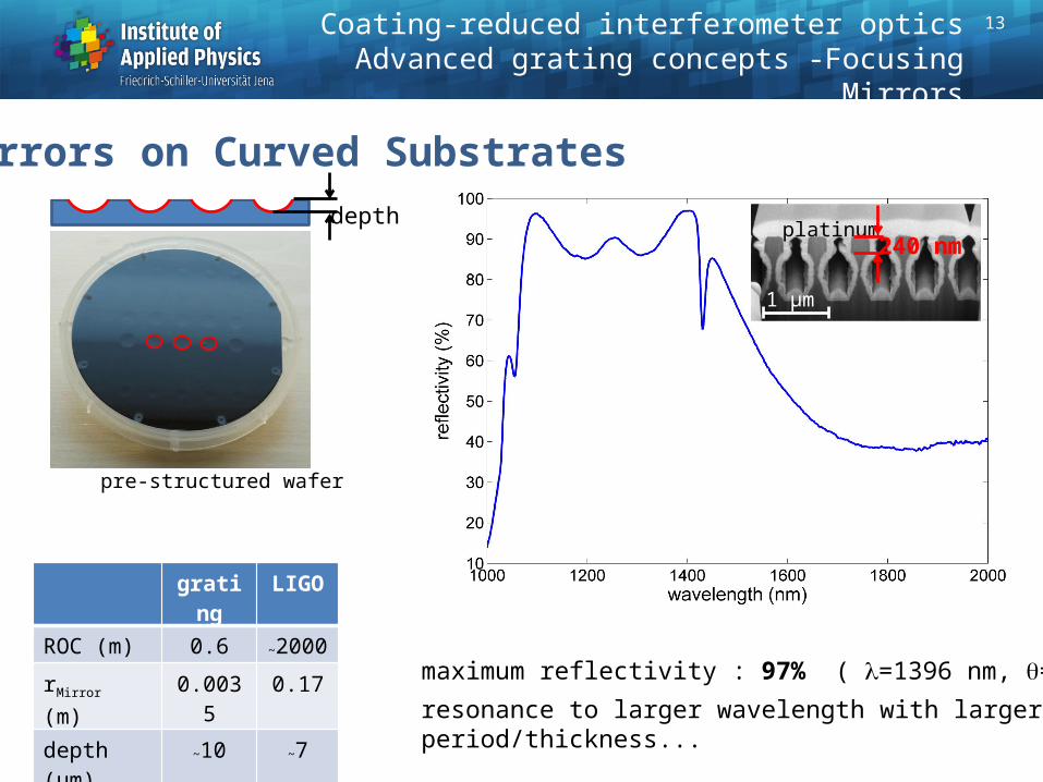
1 µm
platinum240 nm
pre-structured wafer
depth
grating LIGO
ROC (m) 0.6 ~2000
rMirror (m) 0.0035 0.17
depth (µm) ~10 ~7
Coating-reduced interferometer opticsAdvanced grating concepts -Focusing Mirrors
maximum reflectivity : 97% ( l=1396 nm, q=5°)
resonance to larger wavelength with larger period/thickness...
Mirrors on Curved Substrates
13
10
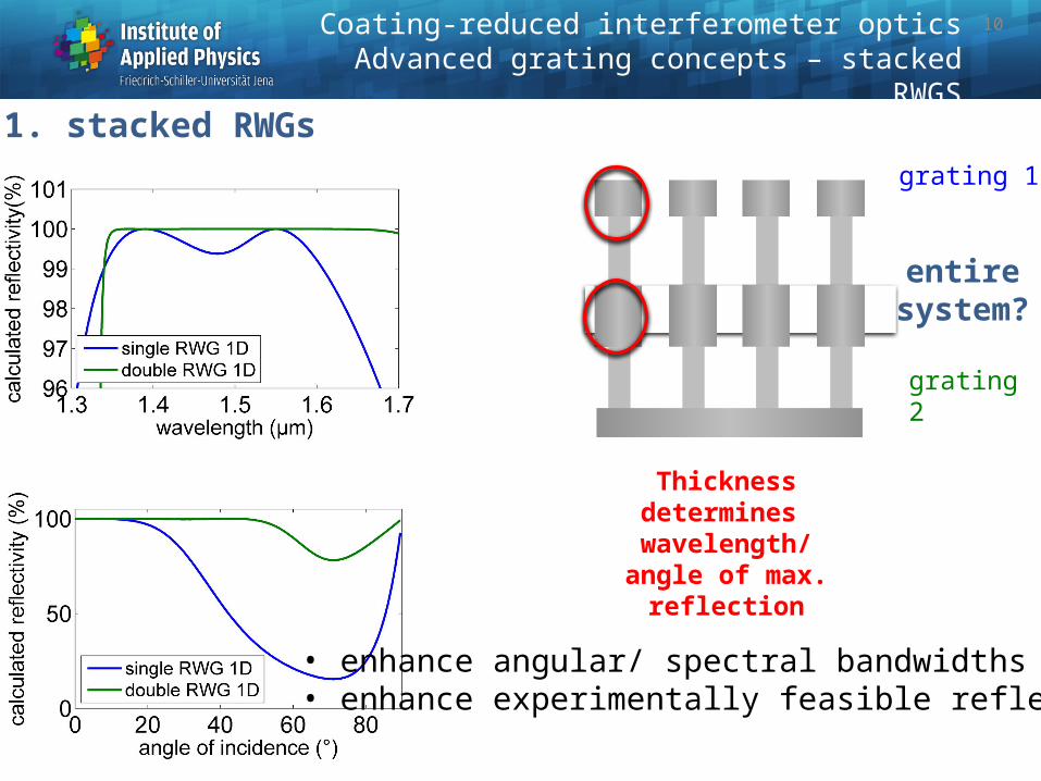
grating 1
grating 2
Thickness determines wavelength/ angle of
max. reflection
entiresystem?
1. stacked RWGs
• enhance angular/ spectral bandwidths• enhance experimentally feasible reflectivity
Coating-reduced interferometer opticsAdvanced grating concepts – stacked RWGS

2. RWGs with 2D periodicity
Coating-reduced interferometer opticsAdvanced Grating Concepts - 2D RWGs
basis for flat focusing mirrors
1 µm
2d a-Si grating
15

Combination von highly efficient mirrors with diffraction grating
high Finesseonly weak perturbation
only 0th order
Highly efficient mirror Diffraction grating
0th, ±1st orders
transversalmodulation:
Grating depth
lateral Modulation:Ridge width/
-position
Coating-reduced interferometer opticsDiffractive elements
16
High angular tolerance of reflector necessary
pmirror<l pdiff= ... 2l l
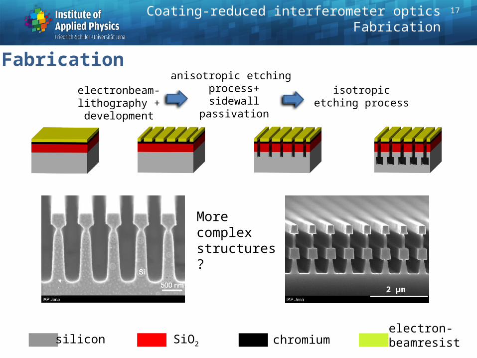
electron-beamresistsilicon SiO2
electronbeam-lithography +development
anisotropic etching process+sidewall
passivation
isotropic etching process
Fabrication
chromium
More complexstructures?
5 µm
Coating-reduced interferometer opticsFabrication
2 µm
17
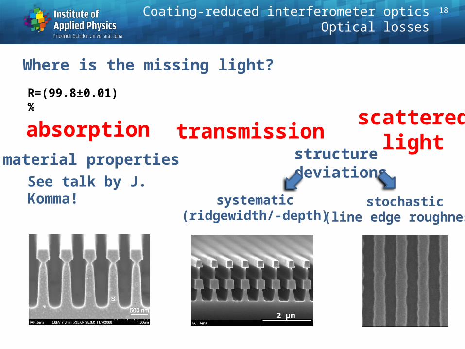
R=(99.8±0.01)%material properties structure
deviations
systematic(ridgewidth/-depth)
transmission
stochastic(line edge roughness)
scatteredlight
absorption
2 µm
Coating-reduced interferometer opticsOptical losses
Where is the missing light?
18
See talk by J. Komma!

high sensitivity
(60 e-/100 nm2)
100 nm ridges and grooves
Line edge roughness due to particle statistics in the lithographic process
10n
m
10n
m
electron impacts
low sensitivity
(8000 e-/100 nm2)
FEP 171 (9.5 µC/cm2)
18M. Heusingen, diploma thesis (2011)
Coating-reduced interferometer opticsOptical losses

20
Grating accuracy
+ 6.3 nm
- 6.6 nm
19 mm
50m
m
position [mm]
pe
riod
va
riatio
n (
pm
)
period variation < 5 pm
wave-front measurement (1 µm period grating + technology, Littrow-Mount, l=633 nm)
significantly better than interferometric gratings
Coating-reduced interferometer opticsOptical losses
wavefront placement
PV 12.8 nm < 10.3 nm
rms 1.4 nm < 1.1 nm

21
Sophisticated device for measurement of scattered light ALBATROSSat Fraunhofer Institute IOF
Measurements of scattered light at 1550 nm set up right now!
Coating-reduced interferometer opticsOptical losses

22
Summary
Coating-reduced interferometer opticsSummary
• RWGs capable of providing high reflectivity • Experiments for higher R running • Origin of optical losses to be identified• Thermal noise to be investigated