large binocular telescope interferometer adaptive … binocular telescope interferometer adaptive...
TRANSCRIPT

Large Binocular Telescope Interferometer Adaptive Optics:On-sky performance and lessons learned
Vanessa P. Baileya, Philip M. Hinza, Alfio T. Puglisib, Simone Espositob, VidhyaVaitheeswarana, Andrew J. Skemera, Denis Defrerea, Amali Vaza, Jarron M. Leisenringa
aSteward Observatory, University of Arizona, 933 N Cherry Ave., Tucson, AZ, USA;bOsservatorio Astrofisico di Arcetri, Largo E. Fermi 5, 50125 Firenze, Italy
ABSTRACT
The Large Binocular Telescope Interferometer is a high contrast imager and interferometer that sits at thecombined bent Gregorian focus of the LBT’s dual 8.4 m apertures. The interferometric science drivers dictate0.1” resolution with 103 − 104 contrast at 10 µm, while the 4 µm imaging science drivers require even greatercontrasts, but at scales >0.2”. In imaging mode, LBTI’s Adaptive Optics system is already delivering 4 µmcontrast of 104 − 105 at 0.3′′ − 0.75′′ in good conditions. Even in poor seeing, it can deliver up to 90% StrehlRatio at this wavelength. However, the performance could be further improved by mitigating Non-CommonPath Aberrations. Any NCPA remedy must be feasible using only the current hardware: the science camera,the wavefront sensor, and the adaptive secondary mirror. In preliminary testing, we have implemented an “eyedoctor” grid search approach for astigmatism and trefoil, achieving 5% improvement in Strehl Ratio at 4 µm,with future plans to test at shorter wavelengths and with more modes. We find evidence of NCPA variability onshort timescales and discuss possible upgrades to ameliorate time-variable effects.
Keywords: Adaptive Optics, Large Binocular Telescope, Infrared, Non-Common Path Aberrations
1. SCIENTIFIC MOTIVATION
Exoplanetary science is maturing as a field, to the point where not only detection but characterization ofexoplanets and their environments is possible. While transit and radial velocity surveys provide populationstatistics for inner planets, and the opportunity to characterize the most closely orbiting ones, they cannot yetcharacterize in detail planets located in the habitable zones of extrasolar systems, much less those in the outerreaches. Direct imaging and spectroscopy are already utilized to characterize the properties of gas giant planetsin wide orbits, and are likely to play a significant role in the future characterization of terrestrial analogues.
High-contrast, high-resolution instrumentation is necessary to achieve these goals. In the outer exosolarsystems, imaging gas giant exoplanets around their bright host stars requires contrasts of 104−106 at separationsof 0.75” or less. Future terrestrial planet finding missions searching for reflected visible light from Earth-likeplanets will require contrasts of 109 or more at even smaller inner working angles. At this level, the aggregatelight reflected by the dust co-orbiting with the planet, it’s “exozodiacal light,” can swamp the planet’s signal.It is essential to understand the exozodi population of nearby stars in order to design effective terrestrial planetfinding surveys in the future.
The Large Binocular Telescope Interferometer (LBTI1–4) will be used to characterize both the exozodi and gi-ant planet populations around nearby stars. The Hunt for Observable Signatures of Terrestrial Systems (HOSTS)survey5 will measure the 10 µm thermal emission from exozodiacal dust. To derive meaningful population statis-tics, LBTI much reach sensitivities of 10–30 zodis (1 zodi is defined as the integrated flux of Earth’s zodiacallight); this requires 10 µm contrasts of up to 104 at 0.1”. Simultaneously, in order to set detection limits of 1− 5Jupiter masses at < 100 AU, the LBTI Exozodi Exoplanet Common Hunt (LEECH) survey6 will require 4 µmcontrasts of 103 − 105 at separations of 0.2 − 1′′.
These two science drivers dictate the design of LBTI and its Adaptive Optics (AO) system. LBTI sits at thecombined bent Gregorian focus of the Large Binocular Telescope’s (LBT) two 8.4 m mirrors. It consists of two
Send email correspondence to VB at [email protected]
arX
iv:1
410.
4634
v1 [
astr
o-ph
.IM
] 1
7 O
ct 2
014

science channels: a 1− 5 µm camera (LMIRCam7,8) and an 8− 13 µm camera (NOMIC9). Exoplanet detectioncan be achieved with “conventional” high-contrast direct imaging at 1 − 5 µm. In this mode, the light fromthe two apertures is not coherently combined, but instead independently imaged on the LMIRCam focal plane.The two images may be either overlapped or separated, depending on whether raw sensitivity or redundant PSFmeasurement is more important to the particular observing goal. However, the resolution set at 10 µm by the8.4 m apertures is too coarse to probe typical exozodi spatial scales. Therefore, LBTI coherently combines thelight from the two LBT apertures to create an interferometer with a baseline of 23 m for this application.10
Both applications require exquisite wavefront control and low thermal background contribution from the opticalelements; these requirements shape the design of the AO system.
In this paper we describe the LBTI AO system hardware and current performance. We detail the effectsof Non-Common Path Aberrations (NCPA) on image quality and our current mitigation strategy. Finally, wedescribe limitations of our current approach and our future plans for NCPA mitigation.
2. LBTI AO HARDWARE
LBTI AO consists of two independent natural guide star adaptive optics systems, one for each LBT aperture.These are near-clones of the LBT First Light AO (FLAO) systems.11 Each system consists of a dedicated visiblelight pyramid wavefront sensor (PWFS) and an Adaptive Secondary Mirror (ASM). A dichroic entrance windowto LBTI sends the < 1 µm wavelength light directly into the PWFS while transmitting the IR light to LBTI.In dual-aperture “binocular” observing mode, each AO system is operated independently. The telescope controlsoftware executes the commands necessary for binocular pointing.
Rather than opting for the traditional AO layout, where deformable mirrors are added to the existing opticaltrain, the LBT has incorporated its deformable mirrors directly into the telescope design in the form of ASMs.12,13
The ASMs can be set in either adaptive mode or fixed mode and are therefore used by both AO and seeing-limited LBT instruments. In other words ASMs nominally replace fixed secondary mirrors at the LBT forall applications. The primary benefit for LBTI of this scheme is that it adds no additional warm optics inthe system.14 With only three warm optics ahead of LBTI (the primary, secondary and tertiary mirrors) thetelescope contribution to the thermal IR background is minimized.
The ASM itself is a voice coil-actuated thin shell design that is robust against actuator failure and can becalibrated on the telescope. Each 0.9 m diameter mirror has 672 voice coil actuators that float the 1.6 mm Zerodurshell above its reference body. Voice coil actuators have a large stroke, negating the need for a “woofer/tweeter”deformable mirror pair, although during closed loop operation, tip/tilt and low order aberrations are periodicallyoffloaded to the telescope active optics to free up ASM stroke. The voice coil design is robust against actuatorfailure. In contrast to microelectromechanical (MEM) mirrors, where failed actuators “stick” in place, failedvoice coil actuators “float,” meaning that although they cannot be actively controlled, they smoothly followthe local mirror figure. Another advantage to the LBT ASM design is that the AO system can be end-to-endcalibrated in situ. This is because the LBT is a Gregorian design, so by placing a retroretlecting optic at the ASMfocus, the ASM can be illuminated by an artificial source built into the wavefront sensor. Our reconstructors arebuilt with a Karhunen Loeve modal basis,12 and we have successfully controlled up to 400 modes on sky.
LBTI, like any AO instrument on LBT, has a dedicated wavefront sensor. Figure 1 details the opticallayout. Our visible light PWFS is nearly identical to the FLAO PWFS,15,16 except that because LBTI has afixed orientation relative to the telescope, we do not need pupil rerotating optics. The heart of the unit is afour-sided pyramid-shaped optic placed at a focal plane in the WFS, where it splits the PSF into 4 quadrants(implementing the Foucault knife-edge test in X and Y simultaneously). These four quadrants are reimagedinto four pupil images on the CCD. The relative intensities of the pixels at corresponding locations in the fourpupil images is determined by the local slope of the wavefront. A modulating tip/tilt mirror placed before thepyramid modulates the PSF around the tip of the pyramid, with typical amplitudes of several λ/D, to increasethe dynamic range of the system by preventing slope saturation.
The most distinct advantage of PWFSs is that the number of subapertures is dictated solely by the numberof pixels across the pupil images; variable CCD binning makes the number of subapertures a dynamic quantity.With this flexibility, LBTI can guide on the brightest stars in the sky as well as those with R ∼ 16 mag. CCD read
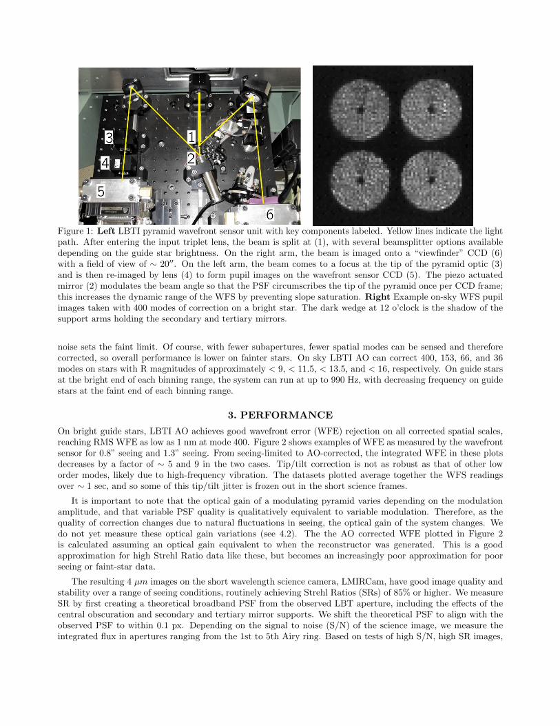
Figure 1: Left LBTI pyramid wavefront sensor unit with key components labeled. Yellow lines indicate the lightpath. After entering the input triplet lens, the beam is split at (1), with several beamsplitter options availabledepending on the guide star brightness. On the right arm, the beam is imaged onto a “viewfinder” CCD (6)with a field of view of ∼ 20′′. On the left arm, the beam comes to a focus at the tip of the pyramid optic (3)and is then re-imaged by lens (4) to form pupil images on the wavefront sensor CCD (5). The piezo actuatedmirror (2) modulates the beam angle so that the PSF circumscribes the tip of the pyramid once per CCD frame;this increases the dynamic range of the WFS by preventing slope saturation. Right Example on-sky WFS pupilimages taken with 400 modes of correction on a bright star. The dark wedge at 12 o’clock is the shadow of thesupport arms holding the secondary and tertiary mirrors.
noise sets the faint limit. Of course, with fewer subapertures, fewer spatial modes can be sensed and thereforecorrected, so overall performance is lower on fainter stars. On sky LBTI AO can correct 400, 153, 66, and 36modes on stars with R magnitudes of approximately < 9, < 11.5, < 13.5, and < 16, respectively. On guide starsat the bright end of each binning range, the system can run at up to 990 Hz, with decreasing frequency on guidestars at the faint end of each binning range.
3. PERFORMANCE
On bright guide stars, LBTI AO achieves good wavefront error (WFE) rejection on all corrected spatial scales,reaching RMS WFE as low as 1 nm at mode 400. Figure 2 shows examples of WFE as measured by the wavefrontsensor for 0.8” seeing and 1.3” seeing. From seeing-limited to AO-corrected, the integrated WFE in these plotsdecreases by a factor of ∼ 5 and 9 in the two cases. Tip/tilt correction is not as robust as that of other loworder modes, likely due to high-frequency vibration. The datasets plotted average together the WFS readingsover ∼ 1 sec, and so some of this tip/tilt jitter is frozen out in the short science frames.
It is important to note that the optical gain of a modulating pyramid varies depending on the modulationamplitude, and that variable PSF quality is qualitatively equivalent to variable modulation. Therefore, as thequality of correction changes due to natural fluctuations in seeing, the optical gain of the system changes. Wedo not yet measure these optical gain variations (see 4.2). The the AO corrected WFE plotted in Figure 2is calculated assuming an optical gain equivalent to when the reconstructor was generated. This is a goodapproximation for high Strehl Ratio data like these, but becomes an increasingly poor approximation for poorseeing or faint-star data.
The resulting 4 µm images on the short wavelength science camera, LMIRCam, have good image quality andstability over a range of seeing conditions, routinely achieving Strehl Ratios (SRs) of 85% or higher. We measureSR by first creating a theoretical broadband PSF from the observed LBT aperture, including the effects of thecentral obscuration and secondary and tertiary mirror supports. We shift the theoretical PSF to align with theobserved PSF to within 0.1 px. Depending on the signal to noise (S/N) of the science image, we measure theintegrated flux in apertures ranging from the 1st to 5th Airy ring. Based on tests of high S/N, high SR images,
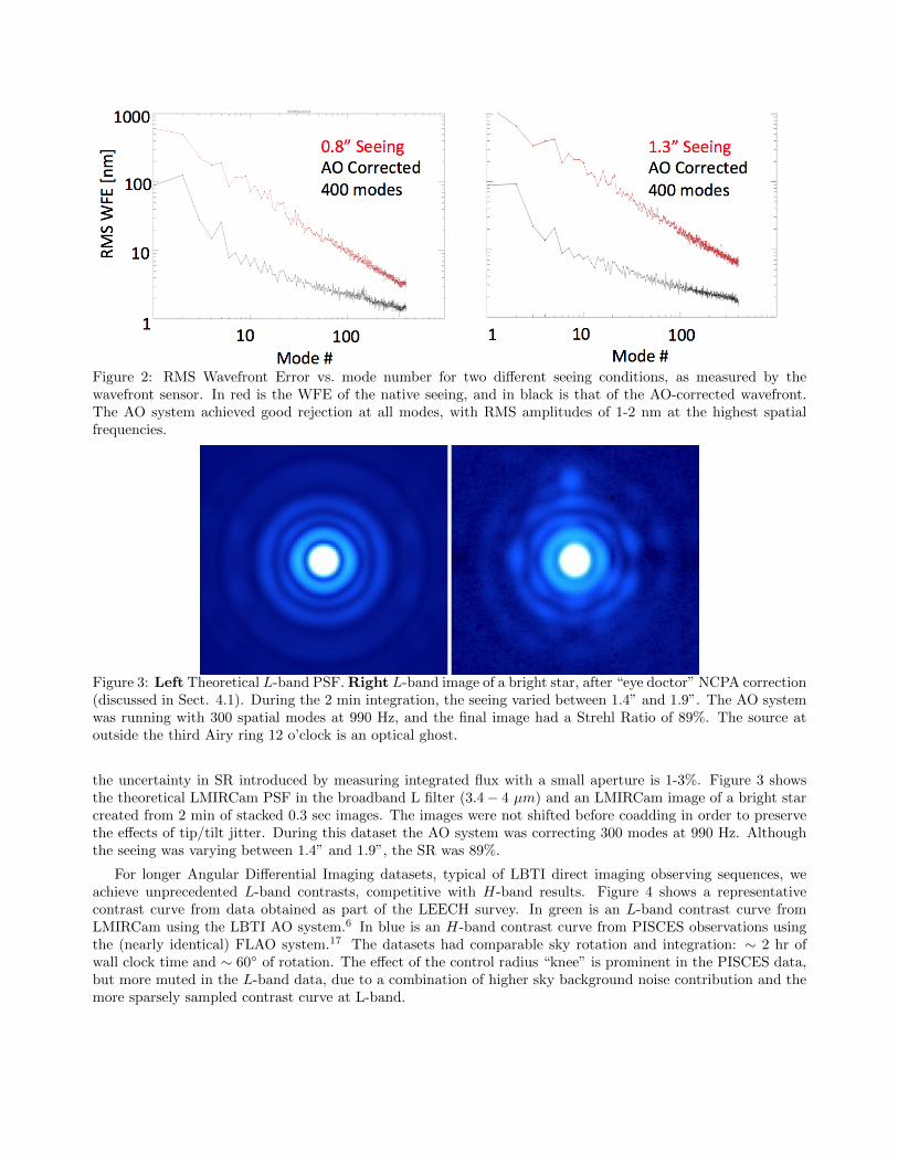
Figure 2: RMS Wavefront Error vs. mode number for two different seeing conditions, as measured by thewavefront sensor. In red is the WFE of the native seeing, and in black is that of the AO-corrected wavefront.The AO system achieved good rejection at all modes, with RMS amplitudes of 1-2 nm at the highest spatialfrequencies.
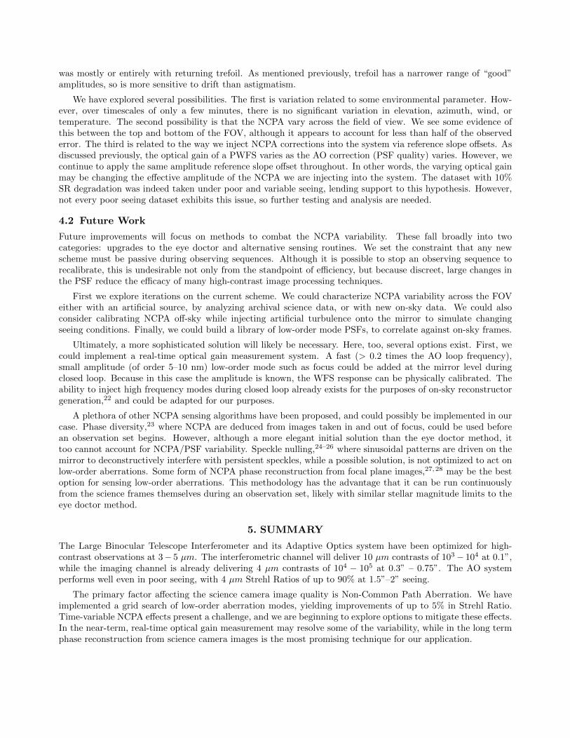
Figure 3: Left Theoretical L-band PSF. Right L-band image of a bright star, after “eye doctor” NCPA correction(discussed in Sect. 4.1). During the 2 min integration, the seeing varied between 1.4” and 1.9”. The AO systemwas running with 300 spatial modes at 990 Hz, and the final image had a Strehl Ratio of 89%. The source atoutside the third Airy ring 12 o’clock is an optical ghost.
the uncertainty in SR introduced by measuring integrated flux with a small aperture is 1-3%. Figure 3 showsthe theoretical LMIRCam PSF in the broadband L filter (3.4 − 4 µm) and an LMIRCam image of a bright starcreated from 2 min of stacked 0.3 sec images. The images were not shifted before coadding in order to preservethe effects of tip/tilt jitter. During this dataset the AO system was correcting 300 modes at 990 Hz. Althoughthe seeing was varying between 1.4” and 1.9”, the SR was 89%.
For longer Angular Differential Imaging datasets, typical of LBTI direct imaging observing sequences, weachieve unprecedented L-band contrasts, competitive with H-band results. Figure 4 shows a representativecontrast curve from data obtained as part of the LEECH survey. In green is an L-band contrast curve fromLMIRCam using the LBTI AO system.6 In blue is an H-band contrast curve from PISCES observations usingthe (nearly identical) FLAO system.17 The datasets had comparable sky rotation and integration: ∼ 2 hr ofwall clock time and ∼ 60◦ of rotation. The effect of the control radius “knee” is prominent in the PISCES data,but more muted in the L-band data, due to a combination of higher sky background noise contribution and themore sparsely sampled contrast curve at L-band.

Figure 4: Contrast curve for bright stars observed with LMIRCam/LBTIAO (green) and PISCES/FLAO (blue).Datasets are comparable in terms of rotation (∼ 60◦) and wall clock time (∼ 2 h). LBTI is delivering the highestcontrast L-band images of any instrument to date.
3.1 NCPA
For bright guide stars and average-to-good seeing conditions, the primary factor limiting LMIRCam image qualityis not the AO-corrected wavefront but Non-Common Path Aberrations (NCPA). The left panel of Figure 5 showsan example LMIRCam 4 µm PSF, and the right panel shows the residuals after subtraction of the PSF azimuthalaverage. The prominent cross pattern is the result of ∼ 200 nm RMS of astigmatism; the effects of ∼ 50 nm oftrefoil are less pronounced. The overall Strehl Ratio of the PSF is ∼ 85%; typical 4 µm SRs range from 80-90%.Theoretical SRs at 4 µm exceed 95%, so mitigating NCPA could significantly impact the image quality delivered.Improving the SR would not only increase the core flux (increase the peak signal on faint companions), but alsodecrease the flux in the first Airy ring and beyond (decrease the photon noise and variability at small innerworking angles). In order to remain competitive with other extreme-AO systems such as GPI,18 SPHERE,19
SCExAO,20 and P1640,21 LBTI must implement NCPA correction.
4. MITIGATING NON-COMMON PATH ABERRATIONS
LBTI does not have dedicated NCPA measurement hardware. We explore solutions that can be executed usingthe science camera and WFS alone to sense NCPA.
4.1 Eye Doctor
We have implemented a simple method for measuring NCPA that we dub the “eye doctor” approach. We runthis routine during set-up for observations. We execute a grid search over one or more low-order aberrations todetermine the amplitude that yields the best PSF on the science camera. We first inject aberrations into the AOsystem by modifying the WFS reference slope offsets, then take a short (< 1 sec) science camera exposure of theresulting PSF. We build slope offsets from the system AO reconstructor itself; the low order Karhunen Loeve

Figure 5: Effects of Non-Common Path Aberrations on LMIRCam 4 µm PSFs. Left: Original PSF withSR∼ 85%. Middle: Residuals after subtraction of azimuthally averaged PSF profile, highlighting asymmetriesin the first Airy ring. Right: PSF after using “eye doctor” routine to correct only astigmatism and trefoil(∼ 200 nm RMS total), yielding SR∼ 90%.
−300nm Z2 −180nm Z2 −60nm Z2 40nm Z2 160nm Z2 280nm Z2 400nm Z2
−300nm Z4 −220nm Z4 −140nm Z4 −40nm Z4 40nm Z4 120nm Z4 200nm Z4
−300nm Z5 −200nm Z5 −100nm Z5 0nm Z5 100nm Z5 200nm Z5 300nm Z5
−300nm Z6 −200nm Z6 −100nm Z6 0nm Z6 100nm Z6 200nm Z6 300nm Z6
Figure 6: Example LMIRCam images (log stretch) from an “eye doctor” grid search of astigmatism and trefoil.The title above each postage stamp is the RMS amplitude and mode number. The varying asymmetry of thefirst Airy ring is the most visible signature of the injected aberrations.
modes approximate astigmatism, trefoil, etc. We search one mode at a time, applying the best amplitude of agiven mode before beginning the search on the next mode. Figure 6 shows an example run including astigmatismand trefoil. Note that a larger amplitude of astigmatism than trefoil is necessary to appreciably impact the PSFmorphology.
Although Strehl Ratio is the metric we are ultimately trying to maximize, we find it is not a robust metricfor evaluation of PSF quality in short exposures. The “peak flux” metric (equivalent to SR) is calculated byfitting a 2D Gaussian profile to the core of the PSF and taking its maximum. The peak flux is quite susceptibleto degradation from tip/tilt jitter as well as to brief seeing bursts. Instead, we use a “symmetry” metric wherewe subtract the azimuthal average of the PSF and sum the absolute value of the residuals outside the PSF core.Figure 7 compares the two metrics for one particularly discrepant run, where the symmetry metric returns asensible value but the peak flux metric does not. The symmetry metric is designed to be sensitive to perturbations

Peak(Vlux(sometimes(wildly(wrong((
15&
−15nm Z4 −11nm Z4 −7nm Z4 −2nm Z4 2nm Z4 6nm Z4 10nm Z4
−15nm Z2 −9nm Z2 −3nm Z2 2nm Z2 8nm Z2 14nm Z2 20nm Z2
−15nm Z5 −10nm Z5 −5nm Z5 0nm Z5 5nm Z5 10nm Z5 15nm Z5
−15nm Z6 −10nm Z6 −5nm Z6 0nm Z6 5nm Z6 10nm Z6 15nm Z6
−15nm Z2 −9nm Z2 −3nm Z2 2nm Z2 8nm Z2 14nm Z2 20nm Z2
−15nm Z4 −11nm Z4 −7nm Z4 −2nm Z4 2nm Z4 6nm Z4 10nm Z4
−15nm Z5 −10nm Z5 −5nm Z5 0nm Z5 5nm Z5 10nm Z5 15nm Z5
−15nm Z6 −10nm Z6 −5nm Z6 0nm Z6 5nm Z6 10nm Z6 15nm Z6
−20 −10 0 10 20
0.4
0.5
0.6
0.7
0.8
0.9
1
Method Comparison
Gauss peakMax 5 pxSymmetry
−20 −10 0 10 200.9
0.92
0.94
0.96
0.98
1
Gauss peak
−20 −10 0 10 20
0.9
0.92
0.94
0.96
0.98
1
amplitude [nm]
Max 5 px
−20 −10 0 10 20
0.4
0.5
0.6
0.7
0.8
0.9
1
amplitude [nm]
Symmetry
O400&&&&&&&O200&&&&&&&&&&0&&&&&&&&&&&200&&&&&&&400&RMS&Amplitude&[nm]&
PSF&Quality&
−20 −10 0 10 20
0.4
0.5
0.6
0.7
0.8
0.9
1
Method Comparison
Gauss peakMax 5 pxSymmetry
−20 −10 0 10 200.9
0.92
0.94
0.96
0.98
1
Gauss peak
−20 −10 0 10 20
0.9
0.92
0.94
0.96
0.98
1
amplitude [nm]
Max 5 px
−20 −10 0 10 20
0.4
0.5
0.6
0.7
0.8
0.9
1
amplitude [nm]
Symmetry
O400&&&&&&&O200&&&&&&&&&&0&&&&&&&&&&&200&&&&&&&400&RMS&Amplitude&[nm]&
Beue
r&&
Figure 7: Comparison of symmetry and peak flux metrics, for a case where the two produce particularly discrepantresults. Top: PSF sequence from LMIRCam, both raw frames and PSF azimuthal average-subtracted frames(core masked). The amplitudes of the aberrations span -300 nm RMS to +300 nm RMS. Bottom: Resultsof symmetry and peak methods for the sequence above. The peak method mistakenly selects the amplitudecorresponding to the image at the far right.
of the brightest Airy ring(s). Although it is well-suited to the effects of low-order NCPA, a different metric maybe necessary for extension to high-order NCPA, whose effects are evident only in lower signal-to-noise regionsof the PSF. We note that azimuthal asymmetry is insensitive to modes such as focus or sphere, except that theeffects of other modes may become more pronounced as the PSF is defocused. Therefore, a hybrid approach,using peak flux for focus-like modes and symmetry for all others, is optimal in some cases.
Several tests of this approach remain. First, we have only had the opportunity to test the eye doctor routineat 4 µm (both narrowband and broadband filters) and with astigmatism, trefoil, and coma. The addition ofmore modes is trivial and we expect it to yield further improvements in SR. Second, we wish to determine whatimprovements can be realized at near-IR wavelengths. A simple scaling with the Marechal approximation tellsus that 90% SR at 4 µm corresponds to SR of 30–70% at J–K bands, and this is left to future testing. Third,we have only tested on R < 7 stars. For efficiency, we would ideally take science camera exposures of 1 sec orless. We expect to have sufficient S/N on the first Airy ring in a single image for L < 8.5− 9 stars. This limit isset by the photon noise from the bright sky background. We estimate that at H-band, where we are read-noiselimited for short exposures, we could reach H = 12.5 mag. For long wavelength observations of targets > 9thmag, it would be expedient to calibrate NCPA in the NIR, because we expect the contribution to NCPA fromthe filters themselves to be small.
We have uncovered limitations to the eye doctor approach. We executed the script once before observations,followed by longer sets of science camera frames to assess PSF quality and stability. Although some sets hadexcellent stability, others exhibited rapid degradation. In the worst example, the SR degraded by 10% in lessthan 10 min after executing the NCPA startup script. In each case where the PSF degraded, the problem
was mostly or entirely with returning trefoil. As mentioned previously, trefoil has a narrower range of “good”amplitudes, so is more sensitive to drift than astigmatism.
We have explored several possibilities. The first is variation related to some environmental parameter. How-ever, over timescales of only a few minutes, there is no significant variation in elevation, azimuth, wind, ortemperature. The second possibility is that the NCPA vary across the field of view. We see some evidence ofthis between the top and bottom of the FOV, although it appears to account for less than half of the observederror. The third is related to the way we inject NCPA corrections into the system via reference slope offsets. Asdiscussed previously, the optical gain of a PWFS varies as the AO correction (PSF quality) varies. However, wecontinue to apply the same amplitude reference slope offset throughout. In other words, the varying optical gainmay be changing the effective amplitude of the NCPA we are injecting into the system. The dataset with 10%SR degradation was indeed taken under poor and variable seeing, lending support to this hypothesis. However,not every poor seeing dataset exhibits this issue, so further testing and analysis are needed.
4.2 Future Work
Future improvements will focus on methods to combat the NCPA variability. These fall broadly into twocategories: upgrades to the eye doctor and alternative sensing routines. We set the constraint that any newscheme must be passive during observing sequences. Although it is possible to stop an observing sequence torecalibrate, this is undesirable not only from the standpoint of efficiency, but because discreet, large changes inthe PSF reduce the efficacy of many high-contrast image processing techniques.
First we explore iterations on the current scheme. We could characterize NCPA variability across the FOVeither with an artificial source, by analyzing archival science data, or with new on-sky data. We could alsoconsider calibrating NCPA off-sky while injecting artificial turbulence onto the mirror to simulate changingseeing conditions. Finally, we could build a library of low-order mode PSFs, to correlate against on-sky frames.
Ultimately, a more sophisticated solution will likely be necessary. Here, too, several options exist. First, wecould implement a real-time optical gain measurement system. A fast (> 0.2 times the AO loop frequency),small amplitude (of order 5–10 nm) low-order mode such as focus could be added at the mirror level duringclosed loop. Because in this case the amplitude is known, the WFS response can be physically calibrated. Theability to inject high frequency modes during closed loop already exists for the purposes of on-sky reconstructorgeneration,22 and could be adapted for our purposes.
A plethora of other NCPA sensing algorithms have been proposed, and could possibly be implemented in ourcase. Phase diversity,23 where NCPA are deduced from images taken in and out of focus, could be used beforean observation set begins. However, although a more elegant initial solution than the eye doctor method, ittoo cannot account for NCPA/PSF variability. Speckle nulling,24–26 where sinusoidal patterns are driven on themirror to deconstructively interfere with persistent speckles, while a possible solution, is not optimized to act onlow-order aberrations. Some form of NCPA phase reconstruction from focal plane images,27,28 may be the bestoption for sensing low-order aberrations. This methodology has the advantage that it can be run continuouslyfrom the science frames themselves during an observation set, likely with similar stellar magnitude limits to theeye doctor method.
5. SUMMARY
The Large Binocular Telescope Interferometer and its Adaptive Optics system have been optimized for high-contrast observations at 3− 5 µm. The interferometric channel will deliver 10 µm contrasts of 103 − 104 at 0.1”,while the imaging channel is already delivering 4 µm contrasts of 104 − 105 at 0.3” – 0.75”. The AO systemperforms well even in poor seeing, with 4 µm Strehl Ratios of up to 90% at 1.5”–2” seeing.
The primary factor affecting the science camera image quality is Non-Common Path Aberration. We haveimplemented a grid search of low-order aberration modes, yielding improvements of up to 5% in Strehl Ratio.Time-variable NCPA effects present a challenge, and we are beginning to explore options to mitigate these effects.In the near-term, real-time optical gain measurement may resolve some of the variability, while in the long termphase reconstruction from science camera images is the most promising technique for our application.

ACKNOWLEDGMENTS
We gratefully acknowledge the hard work and dedication of past and present members of the LBTI team in-cluding: Tom McMahon, Paul Arbo, Teresa Bippert-Plymate, Elwood Downey, Olivier Durney, Paul Grenz,William Hoffmann, Manny Montoya, Mitch Nash, T. J. Rodigas, and Elliot Solheid. We also thank the LBTOstaff for their help and support during our commissioning and observing runs. LBTI is funded by a NASA grantin support of the Exoplanet Exploration Program (NSF 0705296). VB was supported by the NSF GraduateResearch Fellowship Program (DGE-1143953). Observations reported here were obtained at the LBT Observa-tory. The LBT is an international collaboration among institutions in the United States, Italy and Germany.LBT Corporation partners are: The University of Arizona on behalf of the Arizona university system; IstitutoNazionale di Astrofisica, Italy; LBT Beteiligungsgesellschaft, Germany, representing the Max-Planck Society,the Astrophysical Institute Potsdam, and Heidelberg University; The Ohio State University, and The ResearchCorporation, on behalf of The University of Notre Dame, University of Minnesota and University of Virginia.
REFERENCES
1. Hinz, P. M., Solheid, E., Durney, O., and Hoffmann, W. F., “NIC: LBTI’s nulling and imaging camera,”Proceedings of SPIE 7013, 701339 (2008).
2. Hinz, P. M., Bippert-Plymate, T., Breuninger, A., Connors, T., Duffy, B., Esposito, S., Hoffmann, W., Kim,J., Kraus, J., McMahon, T., Montoya, M., Nash, R., Durney, O., Solheid, E., Tozzi, A., and Vaitheeswaran,V., “Status of the LBT Interferometer,” Proceedings of SPIE 7013, 701328 (July 2008).
3. Hinz, P., Arbo, P., Bailey, V., Connors, T., Durney, O., Esposito, S., Hoffmann, W., Jones, T., Leisenring, J.,Montoya, M., Nash, M., McMahon, T., Pinna, E., Puglisi, A., Skemer, A., Skrutskie, M., and Vaitheeswaran,V., “First AO-corrected interferometry with LBTI: steps towards routine coherent imaging observations,”Proceedings of SPIE 8445, 84450U (Sept. 2012).
4. Hinz, P. M., Bailey, V. P., Defrere, D., Downey, E. C., Esposito, S., Hill, J. M., Hoffmann, W. F., Montoya,M., McMahon, T., Puglisi, A. T., Skemer, A. J., Skrutskie, M. F., and Vaitheeswaran, V., “Commissioningthe LBTI for use as a nulling interferometer and coherent imager,” Proceedings of SPIE 9146, in press(2014).
5. Danchi, W. C., Bailey, V., Bryden, G., Defrere, D., Haniff, C. A., Hinz, P. M., Kennedy, G., Mennesson,B., Millan-Gabet, R., Rieke, G. H., Roberge, A., Serabyn, E., Skemer, A., Stapelfeldt, K. R., Weinberger,A., and Wyatt, M., “The LBTI hunt for observable signatures of terrestrial planetary systems: a key NASAscience program on the road to exoplanet imaging missions,” Proceedings of SPIE 9146, in press (2014).
6. Skemer, A. J., Apai, D., Bailey, V. P., Biller, B. A., Bonnefoy, M., Brandner, W., Buenzli, E., Close, L. M.,Crepp, J., Defrere, D., Desidera, S., Eisner, J., Esposito, S., Fortney, J., Henning, T. F. E., Hinz, P. M.,Hofmann, K.-H., Leisenring, J. M., Males, J. R., Millan-Gabet, R., Morzinski, K. M., Pascucci, I., Patience,J., Rieke, G. H., Schertl, D., Schlieder, J. E., Skrutskie, M. F., Su, K. Y. L., Weigelt, G. P., Woodward,C. E., and Zimmerman, N., “High contrast imaging at the LBT: the LEECH exoplanet imaging survey,”Proceedings of SPIE 9148, in press (2014).
7. Skrutskie, M. F., Jones, T., Hinz, P., Garnavich, P., Wilson, J., Nelson, M., and Solheid, E., “The LargeBinocular Telescope mid-infrared camera (LMIRcam): final design and status,” Proceedings of SPIE 7735,77353H (2010).
8. Leisenring, J. M., Skrutskie, M. F., Hinz, P. M., Skemer, A., Bailey, V., Eisner, J., Garnavich, P., Hoffmann,W. F., Jones, T., Kenworthy, M., Kuzmenko, P., Meyer, M., Nelson, M., Rodigas, T. J., Wilson, J. C., andVaitheeswaran, V., “On-sky operations and performance of LMIRcam at the Large Binocular Telescope,”Proceedings of SPIE 8446, 84464F (Sept. 2012).
9. Hoffmann, W. F., Hinz, P. M., Defrere, D., Leisenring, J. M., Skemer, A. J., Arbo, P. A., Montoya, M., andMennesson, B., “Operation and performance of the mid-infrared camera, NOMIC, on the Large BinocularTelescope,” Proceedings of SPIE 9147, in press (2014).
10. Defrere, D., Hinz, P. M., Downey, E. C., Hill, J. M., Mennesson, B., Skemer, A. J., Vaz, A., Ashby, D. S.,Bailey, V. P., Zappellini, G. B., Christou, J. C., Danchi, W. C., Grenz, P., Hoffmann, W. F., Leisenring,J. M., McMahon, T., Millan-Gabet, R., Montoya, M., and Vaitheeswaran, V., “Co-phasing the LargeBinocular telescope: status and performance of LBTI/PHASEcam,” Proceedings of SPIE 9146, in press(2014).

11. Esposito, S., Riccardi, A., Pinna, E., Puglisi, A., Quiros-Pacheco, F., Arcidiacono, C., Xompero, M.,Briguglio, R., Agapito, G., Busoni, L., Fini, L., Argomedo, J., Gherardi, A., Brusa, G., Miller, D. L.,Guerra, J. C., Stefanini, P., and Salinari, P., “Large Binocular Telescope Adaptive Optics System: newachievements and perspectives in adaptive optics,” Proceedings of SPIE 8149, 814902 (2011).
12. Riccardi, A., Xompero, M., Briguglio, R., Quiros-Pacheco, F., Busoni, L., Fini, L., Puglisi, A., Esposito, S.,Arcidiacono, C., Pinna, E., Ranfagni, P., Salinari, P., Brusa, G., Demers, R., Biasi, R., and Gallieni, D.,“The adaptive secondary mirror for the Large Binocular Telescope: optical acceptance test and preliminaryon-sky commissioning results,” Proceedings of SPIE 7736, 77362C (July 2010).
13. Christou, J. C., Brusa Zappellini, G., Guerra Ramon, J. C., Miller, D. L., Wagner, M., and Lefebvre, M. J.,“Living with adaptive secondary mirrors: 365/7/24,” Proceedings of SPIE 9148, in press (2014).
14. Lloyd-Hart, M., “Thermal performance enhancement of adaptive optics by use of a deformable secondarymirror,” Publications of the Astronomical Society of the Pacific 112, 264–272 (2000).
15. Tozzi, A., Stefanini, P., Pinna, E., and Esposito, S., “The double pyramid wavefront sensor for LBT,”Proceedings of SPIE 7015, 701558–701558–9 (2008).
16. Esposito, S., Riccardi, A., Fini, L., Puglisi, A. T., Pinna, E., Xompero, M., Briguglio, R., Quiros-Pacheco,F., Stefanini, P., Guerra, J. C., Busoni, L., Tozzi, A., Pieralli, F., Agapito, G., Brusa-Zappellini, G., Demers,R., Brynnel, J., Arcidiacono, C., and Salinari, P., “First light AO (FLAO) system for LBT: final integration,acceptance test in Europe and preliminary on-sky commissioning results,” Proceedings of SPIE 7736, 773609(July 2010).
17. Skemer, A. J., Hinz, P. M., Esposito, S., Burrows, A., Leisenring, J., Skrutskie, M., Desidera, S., Mesa, D.,Arcidiacono, C., Mannucci, F., Rodigas, T. J., Close, L., McCarthy, D., Kulesa, C., Agapito, G., Apai, D.,Argomedo, J., Bailey, V., Boutsia, K., Briguglio, R., Brusa, G., Busoni, L., Claudi, R., Eisner, J., Fini, L.,Follette, K. B., Garnavich, P., Gratton, R., Guerra, J. C., Hill, J. M., Hoffmann, W. F., Jones, T., Krejny,M., Males, J., Masciadri, E., Meyer, M. R., Miller, D. L., Morzinski, K., Nelson, M., Pinna, E., Puglisi,A., Quanz, S. P., Quiros-Pacheco, F., Riccardi, A., Stefanini, P., Vaitheeswaran, V., Wilson, J. C., andXompero, M., “First Light LBT AO Images of HR 8799 bcde at 1.6 and 3.3um: New Discrepancies betweenYoung Planets and Old Brown Dwarfs,” The Astrophysical Journal 753, 14 (2012).
18. Macintosh, B. A., Graham, J. R., Palmer, D. W., Doyon, R., Dunn, J., Gavel, D. T., Larkin, J., Oppen-heimer, B., Saddlemyer, L., Sivaramakrishnan, A., Wallace, J. K., Bauman, B., Erickson, D. A., Marois,C., Poyneer, L. A., and Soummer, R., “The Gemini Planet Imager: from science to design to construction,”Proceedings of SPIE 7015, 701518 (2008).
19. Dohlen, K., Beuzit, J.-l., Feldt, M., Mouillet, D., Puget, P., Antichi, J., Baruffolo, A., Baudoz, P., Berton,A., Boccaletti, A., Carbillet, M., Charton, J., Claudi, R., Downing, M., Fabron, C., Feautrier, P., Fedrigo,E., Fusco, T., Gach, J.-l., Gratton, R., Hubin, N., Kasper, M., Langlois, M., Longmore, A., Moutou, C.,Petit, C., Pragt, J., Rabou, P., Rousset, G., Saisse, M., Schmid, H.-M., Stadler, E., Stamm, D., Turatto,M., and Wildi, F., “SPHERE, a Planet Finder instrument for the VLT,” Proceedings of SPIE 6269, 62690Q(2006).
20. Guyon, O., Martinache, F., Garrel, V., Vogt, F., Yokochi, K., and Yoshikawa, T., “The Subaru Corona-graphic Extreme AO (SCExAO) System: Wavefront Control and Detection of Exoplanets with CoherentLight Modulation in the Focal Plane,” Proceedings of SPIE 7736, 773624 (July 2010).
21. Hinkley, S., Oppenheimer, B. R., Zimmerman, N., Brenner, D., Parry, I. R., Crepp, J. R., Vasisht, G., Ligon,E., King, D., Soummer, R., Sivaramakrishnan, A., Beichman, C., Shao, M., Roberts, Jr., L. C., Bouchez,A., Dekany, R., Pueyo, L., Roberts, J. E., Lockhart, T., Zhai, C., Shelton, C., and Burruss, R., “A NewHigh Contrast Imaging Program at Palomar Observatory,” Publications of the Astronomical Society of thePacific 123, 74–86 (2011).
22. Pinna, E., Quiros-Pacheco, F., Riccardi, A., Briguglio, R., Puglisi, A., Busoni, L., Arcidiacono, C., Ar-gomedo, J., Xompero, M., Marchetti, E., and Esposito, S., “First on-sky calibration of an high orderadaptive optics system,” Proceedings of SPIE 8447, 84472B (Sept. 2012).
23. Gonsalves, R. A., “Phase retrieval and diversity in adaptive optics,” Optical Engineering 21(5), 829 (1982).
24. Malbet, F., Yu, J. W., and Shao, M., “High-dynamic-range imaging using a deformable mirror for spacecoronography,” Publications of the Astronomical Society of the Pacific 107, 386–398 (1995).

25. Borde, P. and Traub, W., “High-contrast imaging from space: Speckle nulling in a low-aberration regime,”The Astrophysical Journal 638, 488–498 (2006).
26. Savransky, D., Macintosh, B. A., Thomas, S. J., Poyneer, L. A., Palmer, D. W., De Rosa, R. J., and Hartung,M., “Focal plane wavefront sensing and control for ground-based imaging,” Proceedings of SPIE 8447,84476S (Sept. 2012).
27. Codona, J. L. and Kenworthy, M., “Focal Plane Wavefront Sensing Using Residual Adaptive Optics Speck-les,” The Astrophysical Journal 767, 100 (Apr. 2013).
28. Martinache, F., “The Asymmetric Pupil Fourier Wavefront Sensor,” Publications of the Astronomical Societyof the Pacific 125, 422–430 (2013).