1 the status of melody: an interferometer simulation program amber bullington stanford university...
TRANSCRIPT
1
The Status of Melody: An Interferometer Simulation Program
Amber Bullington
Stanford University
Optics Working Group
March 17, 2004
G040131-00-D
2
Outline
Melody overview» Program functionality» New features
Predicting interferometer behavior under thermal load with Melody» Predictions of Power Recycling Cavity Sideband
Gain» Symmetric/Asymmetric Interferometer losses» Mode Shapes
Ref: Beausoleil et al., Model of Thermal Wave-Front Distortion in Interferometric Gravitational Wave Detectors I: Thermal Focusing, JOSA B, June 2003
3
Melody Overview
Simulate thermally loaded interferometer in Matlab» Any passive interferometer configuration
» Gain (ex. recycling cavity gain)
» Thermal lensing, deformation curvature
» Field profiles
Variable parameters: » Input power
» Modulation frequency, depth
» Number of modes
» Test mass parameters: substrate/coating absorption and scattering, curvature, etc.
» Tilt angle
4
Modal Expansion for Self-Consistent Fields
IFO fields represented as a finite set of Hermite-Gauss Modes» X-arm serves as a reference for the basis
IFO described in matrix form» Operators (matrices) for aperture diffraction, wavefront curvature mismatch,
thermal focusing, thermoelastic surface deformation, tilt
Self-consistent fields1. Compute absorbed power in substrate and coatings, update thermal
operators
2. Maximize recycled powera. Independently move ITMs for maximum carrier power
b. Adjust beamsplitter for dark port condition
c. Adjust recycling mirror for maximum recycled carrier power
3. Recompute the intracavity fields and repeat steps 1 and 2 until the recycled power has stabilized to the desired accuracy
5
New Features
Scripts with relevant interferometer parameters» Test mass curvature and substrate absorption from G. Billingsley’s
website
» Relevant mode cleaner configurations also included
Pre-computed file creation more user friendly Field surface plots and beam cross-sections
» Carrier, sidebands plotted directly
» Phase camera emulator (next release)
Test mass tilt Gravitational wave response

6
LIGO PRC Sideband Characteristics
Melody simulates an optimized IFO
Too little thermal loading predicted for LHO 2k, LLO 4k
Too much thermal loading causes early SB rollover in LHO 4k
» Peak gain at 2.5 W input power
» Melody predicts peak gain at 11 W input power
Possible causes:» Optic curvature
» Asymmetric Losses in each arm
5 10 15
10
20
30
40
50
60
TOTAL INPUT POWER (W)
SB
PO
WE
R G
AIN
PRC INDIVIDUAL SB GAIN
carrierupper sblower sb
0 1 2 3 4 50
0.05
0.1
0.15
0.2
INPUT POWER IN EACH SB (W)
AS
SB
PW
R/I
NP
UT
SB
PW
R
FRACTION OF INDIV SB PWR AT AS PORT
upper sblower sb
0 2 4 6 8 100
2
4
6
8x 10
-3
TOTAL INPUT SB POWER (W)
SB
PW
R/I
NP
UT
SB
PW
R
FRACTION OF TOTAL INPUT SB PWR AT AS PORT
0 2 4 6 8 100
5
10
15
TOTAL INPUT SB POWER (W)
TO
TA
L S
B P
OW
ER
GA
IN
PRC SB GAIN
Data from MelodyUsing LHO 4k
Parameters
Peak Gain ~ 35
Data from LHO 4k
2.5W SB Rollover
Peak Gain ~ 25Expected Gain ~ 35
0 20
0.5 4.5Courtesy A. Gretarsson

7
Symmetric vs. Asymmetric Losses
0 2 4 6 8 100
10
20
30
40
50
TOTAL INPUT POWER (W)
SB
PO
WE
R G
AIN
PRC INDIVIDUAL SB GAIN
carrierupper sblower sb
0 2 4 6 8 100
0.1
0.2
0.3
0.4
0.5
TOTAL INPUT POWER (W)
DP
PO
WE
R/I
NP
UT
PO
WE
R P
ER
SB DARK PORT TRANSMISSION
carrierupper sblower sb
0 1 2 3 4 50
0.005
0.01
0.015
0.02
TOTAL INPUT SB POWER (W)
SB
PW
R/I
NP
UT
SB
PW
R
FRACTION OF TOTAL INPUT SB PWR AT AS PORT
0 1 2 3 4 50
2
4
6
8
10
12
TOTAL INPUT SB POWER (W)
TO
TA
L S
B P
OW
ER
GA
IN
PRC SB GAIN
0 2 4 6 8 100
10
20
30
40
50
TOTAL INPUT POWER (W)
SB
PO
WE
R G
AIN
PRC INDIVIDUAL SB GAIN
carrierupper sblower sb
0 2 4 6 8 100
0.1
0.2
0.3
0.4
0.5
TOTAL INPUT POWER (W)
DP
PO
WE
R/I
NP
UT
PO
WE
R P
ER
SB
DARK PORT TRANSMISSION
carrierupper sblower sb
0 1 2 3 4 50
0.005
0.01
0.015
0.02
TOTAL INPUT SB POWER (W)
SB
PW
R/I
NP
UT
SB
PW
R
FRACTION OF TOTAL INPUT SB PWR AT AS PORT
0 1 2 3 4 50
2
4
6
8
10
12
TOTAL INPUT SB POWER (W)
TO
TA
L S
B P
OW
ER
GA
IN
PRC SB GAIN
0 5 10 15 200
10
20
30
40
50
60
TOTAL INPUT POWER (W)
SB
PO
WE
R G
AIN
PRC INDIVIDUAL SB GAIN
carrierupper sblower sb
0 5 10 15 200
0.2
0.4
0.6
0.8
TOTAL INPUT POWER (W)
DP
PO
WE
R/I
NP
UT
PO
WE
R P
ER
SB
DARK PORT TRANSMISSION
carrierupper sblower sb
0 2 4 6 8 100
0.5
1
1.5
2x 10
-3
TOTAL INPUT SB POWER (W)
SB
PW
R/I
NP
UT
SB
PW
R
FRACTION OF TOTAL INPUT SB PWR AT AS PORT
0 2 4 6 8 100
5
10
15
TOTAL INPUT SB POWER (W)
TO
TA
L S
B P
OW
ER
GA
IN
PRC SB GAIN
0 5 10 15 200
10
20
30
40
50
60
TOTAL INPUT POWER (W)
SB
PO
WE
R G
AIN
PRC INDIVIDUAL SB GAIN
carrierupper sblower sb
0 5 10 15 200
0.2
0.4
0.6
0.8
TOTAL INPUT POWER (W)
DP
PO
WE
R/I
NP
UT
PO
WE
R P
ER
SB DARK PORT TRANSMISSION
carrierupper sblower sb
0 2 4 6 8 100
0.5
1
1.5
2x 10
-3
TOTAL INPUT SB POWER (W)
SB
PW
R/I
NP
UT
SB
PW
R
FRACTION OF TOTAL INPUT SB PWR AT AS PORT
0 2 4 6 8 100
5
10
15
TOTAL INPUT SB POWER (W)
TO
TA
L S
B P
OW
ER
GA
IN
PRC SB GAIN
0 2 4 6 8 100
10
20
30
40
50
TOTAL INPUT POWER (W)
SB
PO
WE
R G
AIN
PRC INDIVIDUAL SB GAIN
carrierupper sblower sb
0 2 4 6 8 100
0.2
0.4
0.6
0.8
TOTAL INPUT POWER (W)
DP
PO
WE
R/I
NP
UT
PO
WE
R P
ER
SB DARK PORT TRANSMISSION
carrierupper sblower sb
0 0.2 0.4 0.6 0.8 10
0.2
0.4
0.6
0.8
1
0 2 4 6 8 100
10
20
30
40
50
TOTAL INPUT POWER (W)
SB
PO
WE
R G
AIN
PRC INDIVIDUAL SB GAIN
carrierupper sblower sb
0 2 4 6 8 100
0.2
0.4
0.6
0.8
TOTAL INPUT POWER (W)D
P P
OW
ER
/IN
PU
T P
OW
ER
PE
R S
B DARK PORT TRANSMISSION
carrierupper sblower sb
0 0.2 0.4 0.6 0.8 10
0.2
0.4
0.6
0.8
1
Symmetric, Low Loss Asymmetric, ITMx AR High Loss Symmetric, ITM High Loss
0 20 0 10 0 10
0 20 0 10 0 10
8
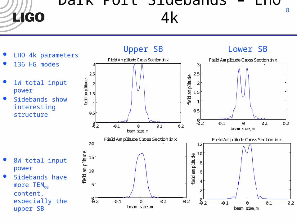
Dark Port Sidebands – LHO 4k
-0.2 -0.1 0 0.1 0.20
0.5
1
1.5
2
2.5
3
beam size, m
fiel
d am
plit
ude
Field Amplitude Cross Section in x
-0.2 -0.1 0 0.1 0.20
0.5
1
1.5
2
2.5
3
beam size, m
fiel
d am
plit
ude
Field Amplitude Cross Section in y
-0.2 -0.1 0 0.1 0.2-4
-2
0
2
4
beam size, m
phas
e, r
adia
ns
Phase Cross Section of Beam in x
-0.2 -0.1 0 0.1 0.2-4
-2
0
2
4
beam size, m
phas
e, r
adia
ns
Phase Cross Section of Beam in y
-0.2 -0.1 0 0.1 0.20
5
10
15
20
beam size, m
field
am
pli
tud
e
Field Amplitude Cross Section in x
-0.2 -0.1 0 0.1 0.20
5
10
15
20
beam size, mfi
eld
am
pli
tud
e
Field Amplitude Cross Section in y
-0.2 -0.1 0 0.1 0.2-4
-2
0
2
4
beam size, m
ph
ase
, ra
dia
ns
Phase Cross Section of Beam in x
-0.2 -0.1 0 0.1 0.2-4
-2
0
2
4
beam size, m
ph
ase
, ra
dia
ns
Phase Cross Section of Beam in y
-0.2 -0.1 0 0.1 0.20
2
4
6
8
10
12
beam size, m
fiel
d a
mp
litu
de
Field Amplitude Cross Section in x
-0.2 -0.1 0 0.1 0.20
2
4
6
8
10
12
beam size, m
fiel
d a
mp
litu
de
Field Amplitude Cross Section in y
-0.2 -0.1 0 0.1 0.2-4
-2
0
2
4
beam size, m
ph
ase,
rad
ian
s
Phase Cross Section of Beam in x
-0.2 -0.1 0 0.1 0.2-4
-2
0
2
4
beam size, m
ph
ase,
rad
ian
s
Phase Cross Section of Beam in y
LHO 4k parameters 136 HG modes
1W total input power Sidebands show
interesting structure
8W total input power Sidebands have more
TEM00 content, especially the upper SB
Upper SB Lower SB
-0.2 -0.1 0 0.1 0.20
0.5
1
1.5
2
2.5
3
beam size, m
fiel
d a
mp
litu
de
Field Amplitude Cross Section in x
-0.2 -0.1 0 0.1 0.20
0.5
1
1.5
2
2.5
3
beam size, m
fiel
d a
mp
litu
de
Field Amplitude Cross Section in y
-0.2 -0.1 0 0.1 0.2-4
-2
0
2
4
beam size, m
ph
ase,
rad
ian
s
Phase Cross Section of Beam in x
-0.2 -0.1 0 0.1 0.2-4
-2
0
2
4
beam size, m
ph
ase,
rad
ian
s
Phase Cross Section of Beam in y
9
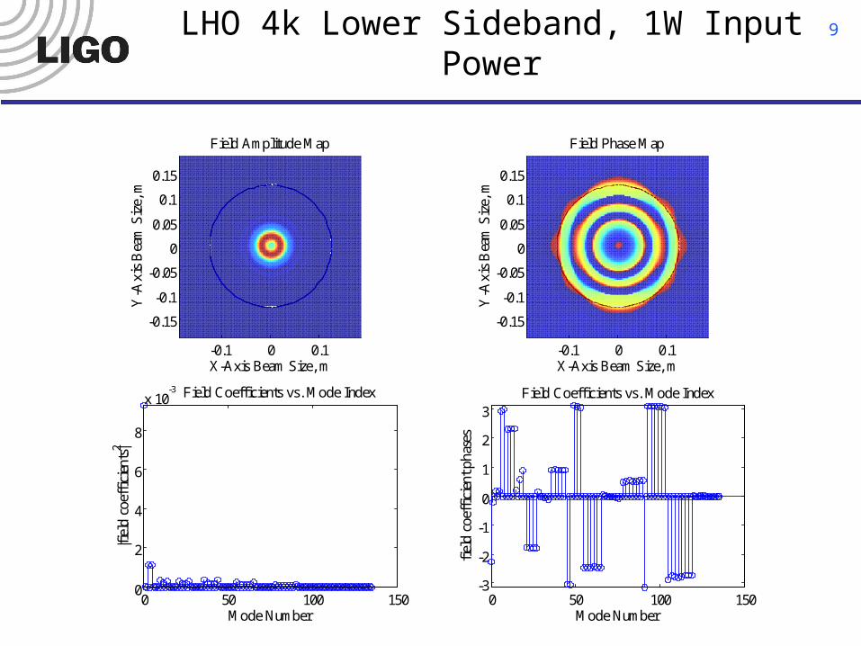
LHO 4k Lower Sideband, 1W Input Power
-0.1 0 0.1
-0.15
-0.1
-0.05
0
0.05
0.1
0.15
X-Axis Beam Size, m
Field Amplitude MapY
-Axi
s B
eam
Siz
e, m
-0.1 0 0.1
-0.15
-0.1
-0.05
0
0.05
0.1
0.15
X-Axis Beam Size, m
Field Phase Map
Y-A
xis
Bea
m S
ize,
m
0 50 100 1500
2
4
6
8
x 10-3
Mode Number
|fiel
d co
effi
cien
ts|2
Field Coefficients vs. Mode Index
0 50 100 150-3
-2
-1
0
1
2
3
Mode Number
fiel
d co
effi
cien
t pha
ses
Field Coefficients vs. Mode Index
10
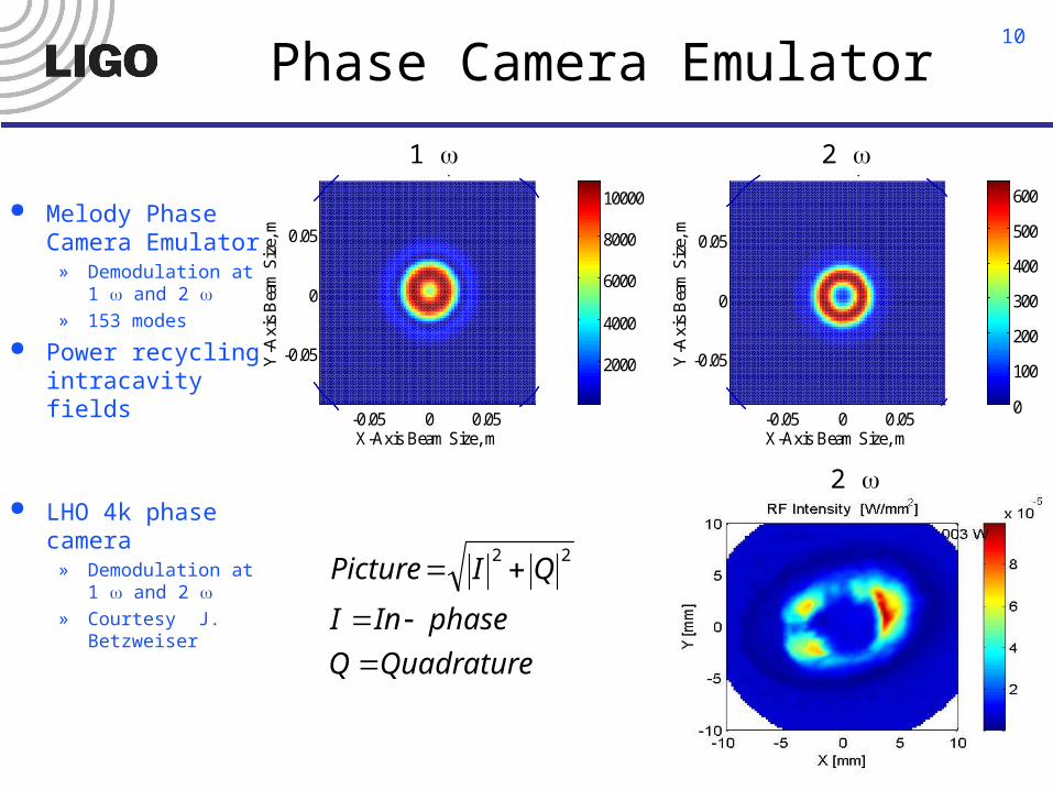
Phase Camera Emulator
Melody Phase Camera Emulator
» Demodulation at 1 and 2
» 153 modes
Power recycling intracavity fields
LHO 4k phase camera
» Demodulation at 1 and 2
» Courtesy J. Betzweiser
2
-0.05 0 0.05
-0.05
0
0.05
X-Axis Beam Size, m
1 w Map
Y-A
xis
Bea
m S
ize,
m
2000
4000
6000
8000
10000
-0.05 0 0.05
-0.05
0
0.05
X-Axis Beam Size, m
2 w Map
Y-A
xis
Bea
m S
ize,
m
0
100
200
300
400
500
600
2 1
QuadratureQ
phaseInI
QIPicture
22
11
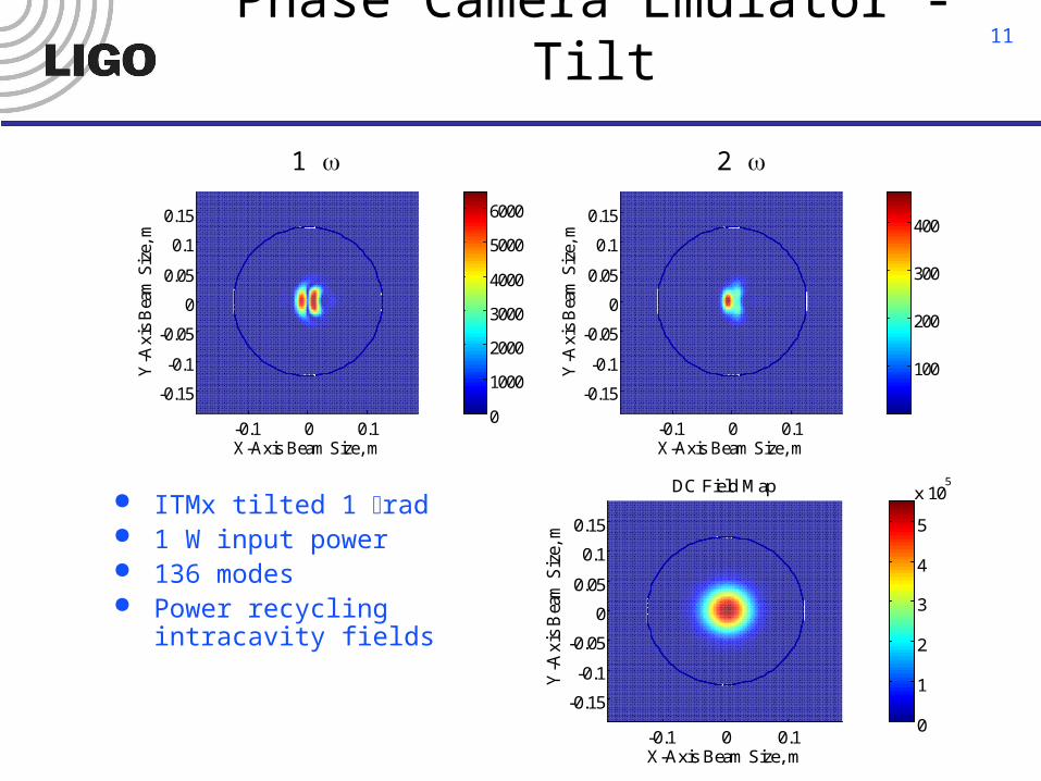
Phase Camera Emulator - Tilt
-0.1 0 0.1
-0.15
-0.1
-0.05
0
0.05
0.1
0.15
X-Axis Beam Size, m
1 w Map
Y-A
xis
Bea
m S
ize,
m
0
1000
2000
3000
4000
5000
6000
-0.1 0 0.1
-0.15
-0.1
-0.05
0
0.05
0.1
0.15
X-Axis Beam Size, m
2 w Map
Y-A
xis
Bea
m S
ize,
m
100
200
300
400
ITMx tilted 1 rad 1 W input power 136 modes Power recycling intracavity
fields
-0.1 0 0.1
-0.15
-0.1
-0.05
0
0.05
0.1
0.15
X-Axis Beam Size, m
DC Field Map
Y-A
xis
Bea
m S
ize,
m
0
1
2
3
4
5
x 105
1 2
12
Summary
Melody uses Hermite-Gauss modes to represent IFO fields
New features can be used to compare IFO behavior to simulations
Recycling cavity gain, mode shapes, thermal lensing, response to asymmetric loss, etc. can be simulated
Next release …» Phase camera emulator» Cross section plots» Astigmatism» Thermal Compensation
And beyond …» Thermal loading with inhomogeneous absorption