cnc applications - mae.ufl.edu manufacturing... · • cnc – computer numerical control Øcnc...
TRANSCRIPT

CNC ApplicationsHistory and Terminology

Background & Definitions (Chapter 1)
• Requirements for a skilled machinist
Ø Serve a 4 year apprenticeship including classes in algebra, trigonometry, print reading, and drafting along with 8,000 hoursof on-the-job-training.
Ø The machinist must purchase several thousand dollars worth of precision tools.
Ø Machinists often make a lower hourly wage than other skilled trades such as electricians and plumbers.
Ø Production operations often require a very skilled person to perform the same operations over and over which most machinists find boring.
Background & Definitions (continued)
• During the 1930’s and 1940’s, there was much labor unrest between machinists and management at large companies. Work stoppages and strikes angered management.
• At the same time, World War II increased the complexity of parts required for common products.
• The most complicated product at the time was the jet aircraft which required large quantities of complex, high-precision components.
Background & Definitions (continued)
• The combination of labor problems and more complicated components precipitated the introduction of automatic machines that could be programmed to produce different parts.
• Automatic machines had been available since the US Civil War (1861-1865), but the machines could only produce one part and required large amounts of time to set up to produce a different part.
• An electronically controlled machine that could be easily changed to produce a different part was required.

Background & Definitions (continued)
• NC – Numerical Control
Ø The first successful electronically programmed automatic machine was a joint project between Massachusetts Institute of Technology (MIT) and the US Air Force in the mid 1950’s. It was a three axis milling machine controlled by a room full of vacuumtube electronics. Even though it was unreliable, it set the stage for modern machines. The controller was called Numerical Control, or NC.
Ø The Electronics Industry Association (EIA) defines NC as "a system in which actions are controlled by the direct insertion of numerical data at some point.“
Ø NC machines were controlled electronically, without the use of acomputer.

Background & Definitions (continued)
• CNC – Computer Numerical ControlØ CNC machines use a computer to assist and improve
functionality of number and code control.
Ø In the 1960’s, CNC machines became available with timesharing on mainframe computers. True NC machines continued to be built.
Ø By the 1970’s, specialized computers were being manufactured for CNC controls. By the late 1970’s, no true NC machines were being made, only CNC.
Ø During the 1980’s, many machine manufactures took advantage of PC technology to increase the reliability and decrease the cost of CNC controls.
Ø Today, all machines are CNC although the term NC is still used, but not in its original definition.
Machine Control Systems
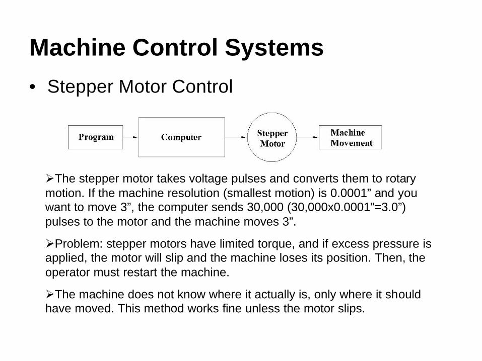
• Stepper Motor Control
ØThe stepper motor takes voltage pulses and converts them to rotary motion. If the machine resolution (smallest motion) is 0.0001” and you want to move 3”, the computer sends 30,000 (30,000x0.0001”=3.0”)pulses to the motor and the machine moves 3”.
ØProblem: stepper motors have limited torque, and if excess pressure is applied, the motor will slip and the machine loses its position. Then, the operator must restart the machine.
ØThe machine does not know where it actually is, only where it should have moved. This method works fine unless the motor slips.

Machine Control Systems (continued)
• Servo Motor Control
ØThe servo motor has a feedback loop to check the machine’s actual position. If the program tells the computer to move 3”, the servo motor starts turning and does not stop until the feedback loop tells the computer that the machine has actually moved 3”
ØAdvantage: servo motors have high torque capabilities to take heavy cuts at high speeds. It stops and gives an alarm when the motor is over-torqued.
ØAdvantage: the machine always knows its actual position.

Modern CNC Machine Characteristics
Ø Massive, usually four times heavier than an equivalent conventional (manual) machine.
Ø Large motors with high speed capabilities to take advantage of modern cutting tools. Horsepower and spindle speeds are generally four to ten times faster than conventional machines.
Ø Automatic tool changers that hold from eight to hundreds of cutting tools that are quickly changed under program control.
Ø High accuracies. The minimum resolution of most machines is 0.0001” or 0.001mm, and some machines are capable of manufacturing parts to that accuracy, depending on the process. Ball screws practically eliminate backlash (slop) in the movement screws.

Modern CNC Machine Accuracy
ØAccuracy of CNC machines depends on their rigid construction, care in manufacturing, and the use of ball screws to almost eliminate slop in the screws used to move portions of the machine. These pictures show the precision balls which re-circulate in the nut.
Photo courtesy Thompson Ball Screw.
Graphic courtesy BSA Co.

Tailstock Bed
Saddle
Cross Slidewith Turret
Headstock
Chuck
Cutter
+Z Direction
+X Direction
CNC ApplicationsIntroduction to Turning Centers

Turning CentersA Turning Center is simply a CNC lathe with a multi-station turret and an enclosure.
Tailstock Bed
Saddle
Cross Slidewith Turret
Headstock
Chuck
Cutter
+Z Direction
+X Direction
Notice the turret attached to the cross slide.
Note: the CNC control and the enclosure are not shown.

Characteristics of Turning Centers
• Turret is on the far side to ease part loading and unloading.
• Heavy for increased rigidity.• High spindle speeds to effectively use hard
cutters.• Powerful motors.• Communication capabilities.

Haas SL-20A Typical Turning Center
The Haas SL-20 turning center has a 20 HP motor, 45-4000 RPM spindle, ten tools in the turret, 8" cutting diameter and 20" between centers. It weighs 9000 lbs.
Turning Center Coordinate System
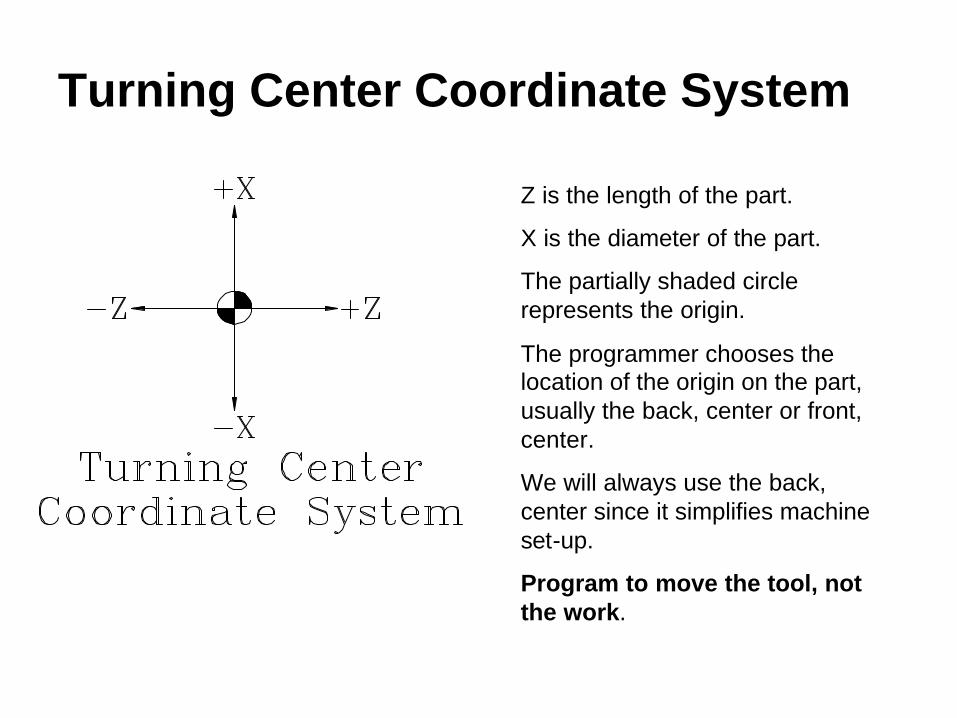
Z is the length of the part.
X is the diameter of the part.
The partially shaded circle represents the origin.
The programmer chooses the location of the origin on the part, usually the back, center or front, center.
We will always use the back, center since it simplifies machine set-up.
Program to move the tool, not the work.
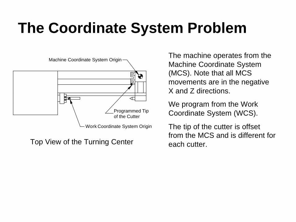
The Coordinate System Problem
The machine operates from the Machine Coordinate System (MCS). Note that all MCS movements are in the negative X and Z directions.
We program from the Work Coordinate System (WCS).
The tip of the cutter is offset from the MCS and is different for each cutter.
Machine Coordinate System Origin
Work Coordinate System Origin
Programmed Tipof the Cutter
Top View of the Turning Center

The Solution
• We can easily measure the distance from the MCS to the WCS and enter it into the machine control. This is called a Fixture Offset.
• We can easily measure the distance from the MCS to the tip of the each cutter and enter the values in the machine control. These values are called Tool Offsets.
Separating the Programmer from the Machine• The programmer chooses the WCS on the centerline of
the part, generally at the back, and then programs the cutter movement from there.
• The programmer calls the correct fixture offset and tool offset numbers in the program (we’ll cover these codes later).
• So, the programmer does not have to be concerned with any machine specific measurements.
Incremental vs. Absolute Programming
AB
CD
E
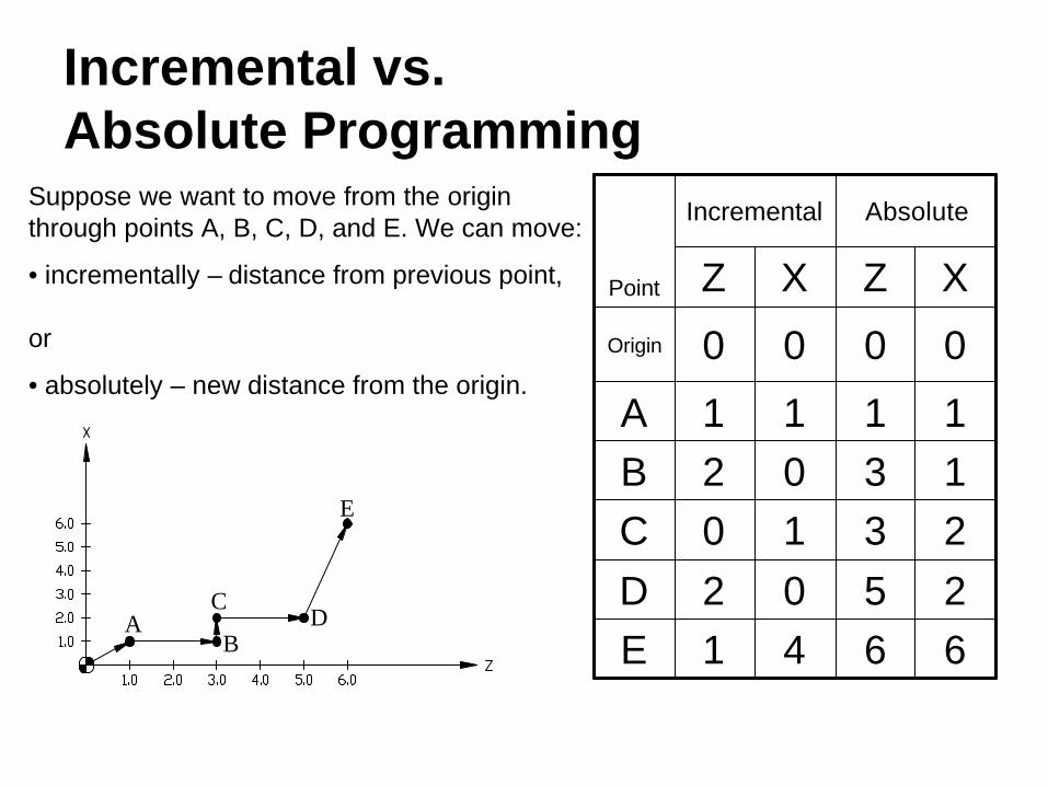
Suppose we want to move from the origin through points A, B, C, D, and E. We can move:
• incrementally – distance from previous point,
or
• absolutely – new distance from the origin.
1302B
0000Origin
6641E2502D2310C
1111A
XZXZ
AbsoluteIncremental
Point

Incremental vs. Absolute Programming (continued)• Notice in the previous table that each move in
incremental mode is the distance from the previous point, while each move in absolute is the distance from the origin, regardless of the previous point.
• Most programmers initially think incremental programming is easier.
• However, editing for program changes is much easier in absolute mode.
• About 95% of all programming is done in absolute mode.• The remaining 5% is for special cases such as repetitive
features where incremental can be a real time saver.
Photo courtesy ISCAR Metals.
CNC ApplicationsSpeed and Feed Calculations

Turning Center Cutters
What types of cutters are used on CNC turning Centers?Ø Carbide (and other hard materials) insert turning
and boring toolsØ High Speed Steel (HSS) drills and taps
Where do I find information for calculating RPM and feed rates?Ø Cutting tool manufacturer (first choice)Ø Machining Data HandbookØ Machinery’s Handbook (we’ll use this option)

Standard Insert ShapesV – used for profiling, weakest insert, 2 edges per side.
D – somewhat stronger, used for profiling when the angle allows it, 2 edges per side.
T – commonly used for turning because it has 3 edges per side.
C – popular insert because the same holder can be used for turning and facing. 2 edges per side.
W – newest shape. Can turn and face like the C, but 3 edges per side.
S – Very strong, but mostly used for chamfering because it won’t cut a square shoulder. 4 edges per side.
R – strongest insert but least commonly used.
See the “Tooling” thumb tab in the Machinery’s Handbook.
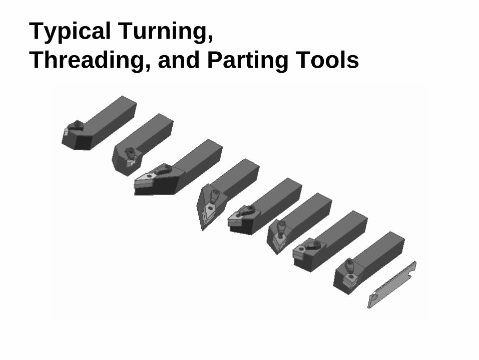
Typical Turning, Threading, and Parting Tools
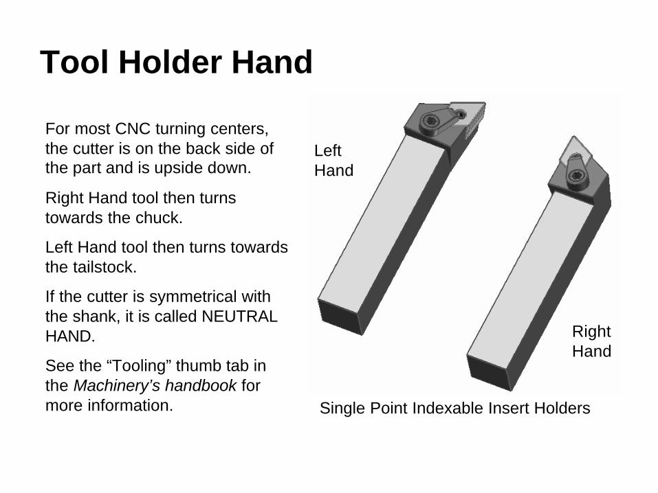
Tool Holder Hand
For most CNC turning centers, the cutter is on the back side of the part and is upside down.
Right Hand tool then turns towards the chuck.
Left Hand tool then turns towards the tailstock.
If the cutter is symmetrical with the shank, it is called NEUTRAL HAND.
See the “Tooling” thumb tab in the Machinery’s handbook for more information.
Left Hand
Right Hand
Single Point Indexable Insert Holders

Tooling Considerations
• Tooling choices depend on the type of workpiece, the machine, and the desired surface finish.
• Harder workpieces require harder cutters.• Modern cutters require the turning center to have
high spindle speeds and powerful motors.

Cutting Speed
• What is cutting speed?– Not RPM– Relative speed of the work and cutter– Units in feet/minute (fpm)– Usually designated as V, cs, or S– Tabulated in the book based on material, cutter
type, and type of cut (roughing or finishing)– Needed to calculate RPM

Calculating Turning RPM
• The formula for calculating RPM is given on page 1016 as:
Where V = cutting speed to be looked up in the handbookp = 3.14D = diameter being cut
When punching buttons on your calculator, do this:
Note the difference between this and the actual formula.To use this formula, we must first find V in the handbookSee page 1022 for a list of the tables.
DV
RPMN××
==π12
=÷÷× DV π12

Types of Cuts
• Roughing – primary considerations:ØJust removing metal, surface finish does not matter.ØRequires a strong cutter.ØGenerally have deep depth of cuts and fast feed
rates.ØThe cutting speed is generally adjusted slower to
keep heat down.

Types of Cuts (continued)
• Finishing – primary considerations:ØMust meet required surface finish and size
specifications.ØRequires a hard cutter to hold its shape well.ØGenerally have small depth of cuts and slow feed
rates.ØThe cutting speed is generally adjusted upward to
give a better surface finish.
Surface Finish Requirements
Insert
h
Feed
N o s e R a d i u s
rf
h×
=8
2
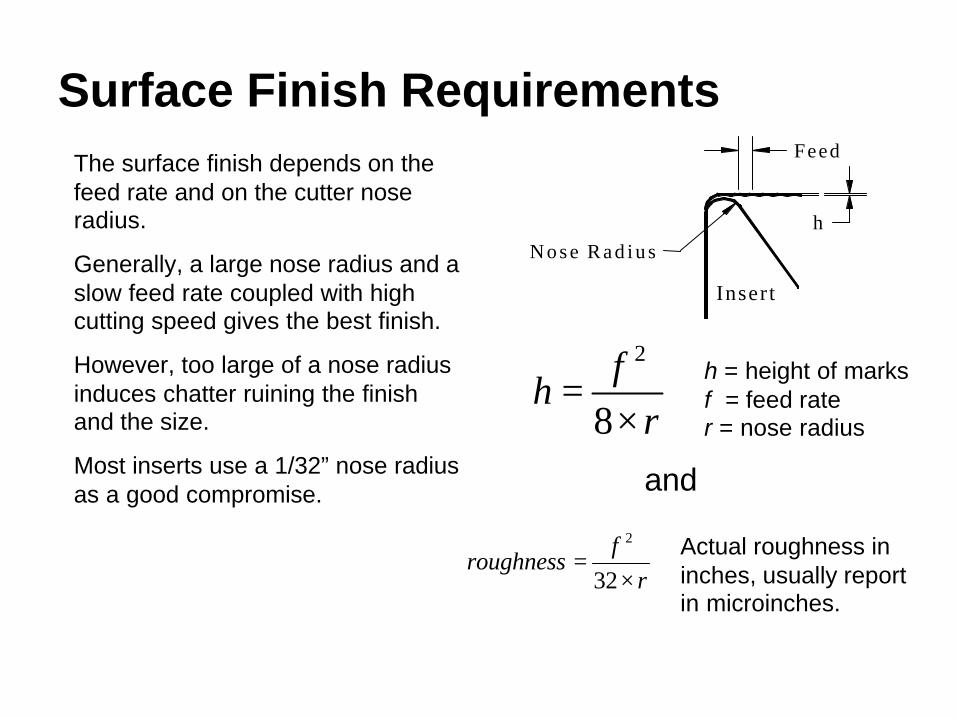
The surface finish depends on the feed rate and on the cutter nose radius.
Generally, a large nose radius and a slow feed rate coupled with high cutting speed gives the best finish.
However, too large of a nose radius induces chatter ruining the finish and the size.
Most inserts use a 1/32” nose radius as a good compromise.
rf
roughness×
=32
2
h = height of marksf = feed rater = nose radius
Actual roughness in inches, usually report in microinches.
and

General Feed and Depth of Cut Recommendations• Roughing:Ø 0.1” to 0.25” depth of cut (radial)Ø 0.012 inches per revolution (ipr) to 0.018 ipr feed rate
• Finishing:Ø 0.03” to 0.05” depth of cut (radial)Ø 0.006 ipr to 0.010 ipr feed rate
Note 1: the depth of cut should not be less than the tool nose radius unless special finishing inserts are being used.Note 2: smaller feed rates can be used if special finishing inserts are being used.

Calculating RPM for Turning Operations with Hard Cutters
• Use this procedure for carbide, ceramic, and cermet inserts.
• We will adjust the cutting speed based on the desired depth of cut and feed rate.
Calculating Turning RPM (continued)
Six step process:1. Select depth of cut - as deep as possible.2. Select feed - appropriate for roughing or finishing.3. Find the original cutting speed in the tables. (See the listing
on page 1022 for the appropriate table.)4. Find the feed and depth of cut factors in Table 5a,
page 1035.5. Modify the original cutting speed based on step 4.6. Calculate the RPM.
Note: All data will be found in the “Machining” thumb tab in theMachinery’s Handbook.

Calculating Turning RPM (continued)
Example: Take 0.250 depth of cut, 0.012 feed in quenched and tempered 8620 steel with a Brinell hardness of 300, hard coated carbide cutter, 2.5” diameter part.
Step 1: Depth of cut given at 0.25”.
Step 2: Feed rate given as 0.012 ipr.

Calculating Turning RPM (continued)Step 3: From Table 1, page 1029, locate cutting parameters for this material
Material
Hardness
Cutting Parameters

Calculating Turning RPM (continued)
Step 3 (continued): From Table 1, page 1029, we find
Vopt = 585 fpm ipr Vavg = 790 fpm Fopt = 0.017
Note that the table lists cutting speed as S rather than V as used everywhere else. Note that the feed rates are given in 0.001 ipr, so the 17 listed for Fopt is actually 0.017 ipr.

Calculating Turning RPM (continued)
Step 4: Once we have located the optimum and average cutting speeds and the optimum feed, we finish our calculation using the data and process described in Table 5A, page 1035.

Calculating Turning RPM (continued)First,
calculate the ratio of the feeds.
Second, calculate the ratio of the cutting speeds
Third, find the feed factor where the step 1 row and step 2 column cross.
Fourth, determine the nearest depth of cut and
lead angle column
Fifth, find the depth of cut factor where the step 1row crosses the step 4 column.
Sixth, calculate the final cutting speed.
Calculating Turning RPM (continued)
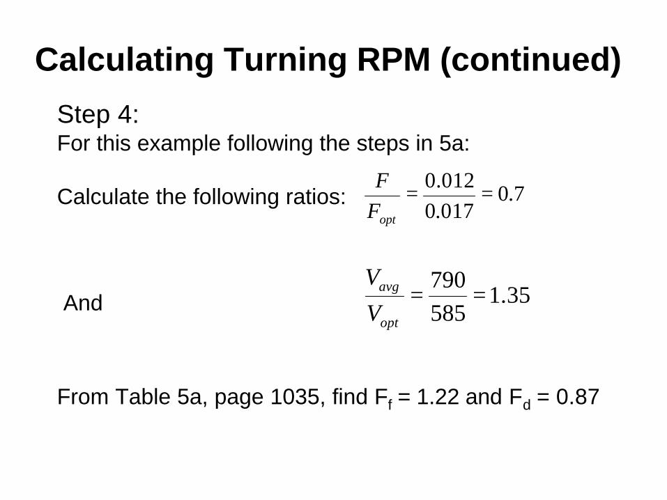
Step 4: For this example following the steps in 5a:
Calculate the following ratios:
And
From Table 5a, page 1035, find Ff = 1.22 and Fd = 0.87
7.0017.0012.0 ==
optFF
35.1585790
==opt
avg
V
V

Calculating Turning RPM (continued)
Step 5: As shown at the bottom of Table 5a,
V = Vopt Ff Fd
Where V = cutting speed to be used (fpm)Vopt = optimum cutting speed from the table
based on material hardness and type ofcutter
Ff = feed factor from Table 5aFd = depth of cut factor from Table 5a
For this example, V = (585)(1.22)(0.87) = 621 fpm

Calculating Turning RPM (continued)Step 6: Finally, calculate the RPM with
For this example:
RPM = 12 x 621 ÷ p ÷ 2.5 = 949 RPM
DV
RPMN××
==π12

CNC ApplicationsProgramming Turning Centers
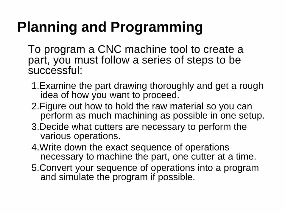
Planning and ProgrammingTo program a CNC machine tool to create a part, you must follow a series of steps to be successful:1.Examine the part drawing thoroughly and get a rough
idea of how you want to proceed.2.Figure out how to hold the raw material so you can
perform as much machining as possible in one setup.3.Decide what cutters are necessary to perform the
various operations.4.Write down the exact sequence of operations
necessary to machine the part, one cutter at a time.5.Convert your sequence of operations into a program
and simulate the program if possible.

What is a block?
• The machine reads the program one line at a time.• Each line is called a block.• Blocks do not extend past one line.• The order of information on a block does not matter:
• However, most programmers use the following order:
• We’ll go over the meaning of each letter as the course progresses.
G0 X3.0 Z1.75 is the same as Z1.75 G0 X3.0
N G X Y Z I J K U V W A B C P Q R F S T M H

G and M Codes
The machine operation is divided into two basic types:ØG codes also called preparatory codesq tell the machine what type of movement or
function should be performed. For example, rapid moves, linear feed moves, arc feed moves, thread cutting, etc.
ØM codes also called miscellaneous functionsq turn the spindle on and off, coolant on and off,
etc.
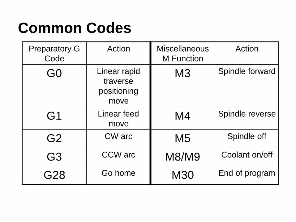
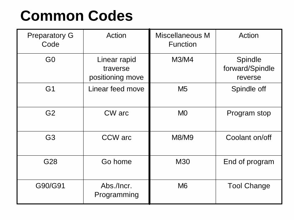
Common Codes
End of programM30Go homeG28
Coolant on/offM8/M9CCW arcG3
Spindle offM5CW arcG2
Spindle reverseM4Linear feed move
G1
Spindle forwardM3Linear rapid traverse
positioning move
G0
ActionMiscellaneous M Function
ActionPreparatory G Code
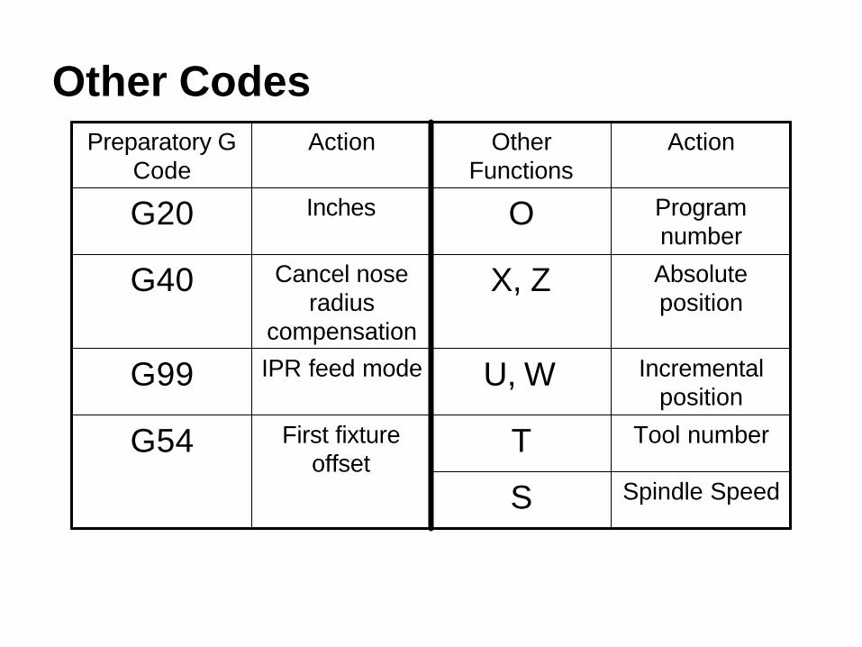
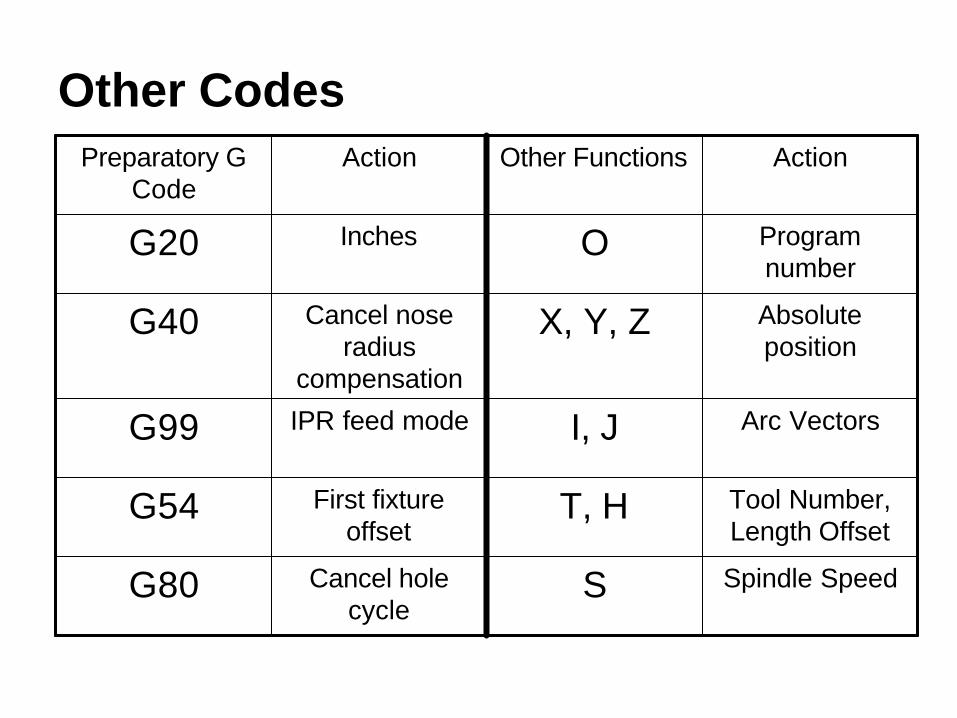
Other Codes
Spindle SpeedS
Tool numberTFirst fixture offset
G54
Incremental position
U, WIPR feed modeG99
Absolute position
X, ZCancel nose radius
compensation
G40
Program number
OInchesG20
ActionOther Functions
ActionPreparatory G Code

Modal
• Most codes are modal – they stay in effect until something changes them.
• We only program what changes, nothing extra. For example:
G0 Z3.0G0 X2.0 Z3.0G1 X2.0 Z1.5 F0.012G1 X2.5 Z1.5 F0.012
G0 Z3.0X2.0G1 Z1.5 F0.012X2.5
Difficult to follow, and changes require considerable effort.
Easy to read and change!
Works, but poor stylePreferred

Notes on Turning Center G & M Codes• Most machines only allow one M code per block.• The capital “Oh” for the program number is the only “Oh”
in the program. All others are zeros (0). Be sure you do not mistype.
• The tool code (T) is four digits – the first two for the tool number, the second two for the offset number. They are usually the same.
• All alpha characters must be in uppercase.

Notes on Number Formats
All numbers except zero require a decimal point, otherwise the machine defaults to its resolution. For example:
X3.0 works fineX3. works fineX3 the machines interprets as X0.0003Z0 works fineZ0. works fine

Special Notes for Sending a Turning Center Home• The G28 code is used to send the machine home.• G28 requires a move through an intermediate point.• We generally position the tool clear of the part before
sending it home, so the intermediate point is not used.• To give it a point, we incrementally program a 0
movement like this:– G28 U0 which means go home in X incrementally
through a point 0 distance from the current location– G28 W0 means the same for the Z direction

Program Functions Fall into just Four (4) Categories1. Program Start2. Tool Change3. Program End4. Machining Functions
The first 3 are generally the same for all programs for a given machine.
Note that they will be different for different machines. You must know your machine by reading the machine manual!

Program Functions for the Haas SL-20 Turning Center• The CNC language is not 100% standard across all
machine and control manufacturers.• Haas machines use fairly generic programming that is
similar to most Fanuc compatible machines. Fanuc is probably the most common machine controller.
• Again, you must know your machine by reading the machine manual!

Haas SL-20 Program Start
Starting character for file transferProgram number set to 999, note the capital “Oh”Initial conditionsGo home in the X directionGo home in the Z directionLoad tool 2 with offset 2Load the first fixture offsetSet the spindle to 4000 RPM in the forward directionRapid to the first Z location, zzz is the numerical valueRapid to the first X location (G0 is modal), turn the coolant on, xxx is the numerical value
Machining moves follow
%O999G20 G40 G99G28 U0G28 W0T0202G54S4000 M3G0 ZzzzXxxx M8...
ExplanationProgram

Haas SL-20 Tool Change
Turn the coolant offGo home in the X directionGo home in the Z directionLoad the next tool and offsetLoad the fixture offsetSet the spindle speed and directionRapid to the first Z location, zzz is the numerical valueRapid to the first X location (G0 is modal), turn the coolant on, xxx is the numerical value
Machining moves follow
M9G28 U0G28 W0T0303G54S3500 M3G0 ZzzzXxxx M8...
ExplanationProgram

Haas SL-20 Program End
Turn the coolant offTurn the spindle offGo home in the X directionGo home in the Z directionEnd of program M codeEnd of file character for file transfer
M9M5G28 U0G28 W0M30%
ExplanationProgram

A Simple Turning Center Program
Problem Statement:
Face up to 1/8” (0.125”) off the end of a 1.250” diameter 1117 CD steel bar that is 175 Hb using a hard, coated carbide C shaped insert at 0.004 ipr feed.
0.125
2.250
1.250
Material: 1117 CD Steel 175HB

Follow Planning and Programming Steps (1-3)
1. Examine drawing2. How will we hold the raw material – in a collet.3. Decide what cutters to use – given hard, coated
carbide C shaped insert. Since f<favg, use Vavg=1410 fpm giving
448025.1
14101212=
××
=××
==ππ D
VRPMN
Since the machine only goes 4500RPM, we’ll use 4000RPM to stay a little under the maximum.
Follow Planning and Programming Steps (4)
4. Write down the exact sequence of operations:A. Rapid position the cutter in ZB. Rapid position the cutter 0.1” away from the part
in XC. Face to X0. at F0.004D. Move away 0.050” in ZE. Rapid position 0.1” away from the part in XF. Program end.
Follow Planning and Programming Steps (5)
5. Convert the sequence of operations to a program:
Program StartFacing
Program End

The Actual Program
Program Start
A. Rapid to position in ZB. Rapid 0.1 away from part (0.2 on diameter)C. Feed to X is 0 (center of the part)D. Feed 0.050” away from the faceE. Rapid back to 0.1” away from part in X
F. Rapid home in XG. Rapid home in Z
Program End
% O999G20 G40 G99 G28 U0 G28 W0T0202 G54 S4000 M3 G0 Z2.25X1.350 M8G1 X0 F.006Z2.3G0 X1.350M9 M5 G28 U0 G28 W0 M30 %
ActionProgram Codes

Cutter atHome Position
A
B Cutter in Positionto Cut
CFacingCutMove
Small Clearance
D
Rapid MoveClear of Part
E
Rapid Home First in XThen in Z
G
F
(Program Start)
What the Machine Does

An Animation of the Machine’s Movement
Select this link to start the animation.
Notes on the animation:
1. The isometric view orientation is the same as the earlier views of the complete machine with the tailstock to the right.
2. The animation shows the motion of the cutter, but it does not differentiate between rapid and feed moves.
3. The cutter is upside-down because the spindle is going forward (CCW is this view) and the cutter is on the back side of the part.
4. Sorry, I can’t make the part rotate or chips fly!

Running a Program for the First Time
1.Install all cutters in the proper holders.2. Install the fixture or chuck on the machine and
establish the WCS.3. Set the cutter offsets.4. Simulate the program on the machine.5. Slow rapid traverse down as low as possible.6. Initiate the single step cycle with your hand on the
E-stop button at all times.7. Carefully watch the operations, press the feed hold
button to take notes for any corrections.8. Install a part and go to step 5.

CNC ApplicationsIntroduction to Machining Centers

Machining Centers
A machining center is simply a CNC milling machine with an automatic tool changer and an enclosure.
There are a number of different types of machining centers differentiated by the number of programmable axes.
Three Axis Machining Center
Column
Spindle Motor
Table
Saddle
Head
XY
Z
Cutting Tool
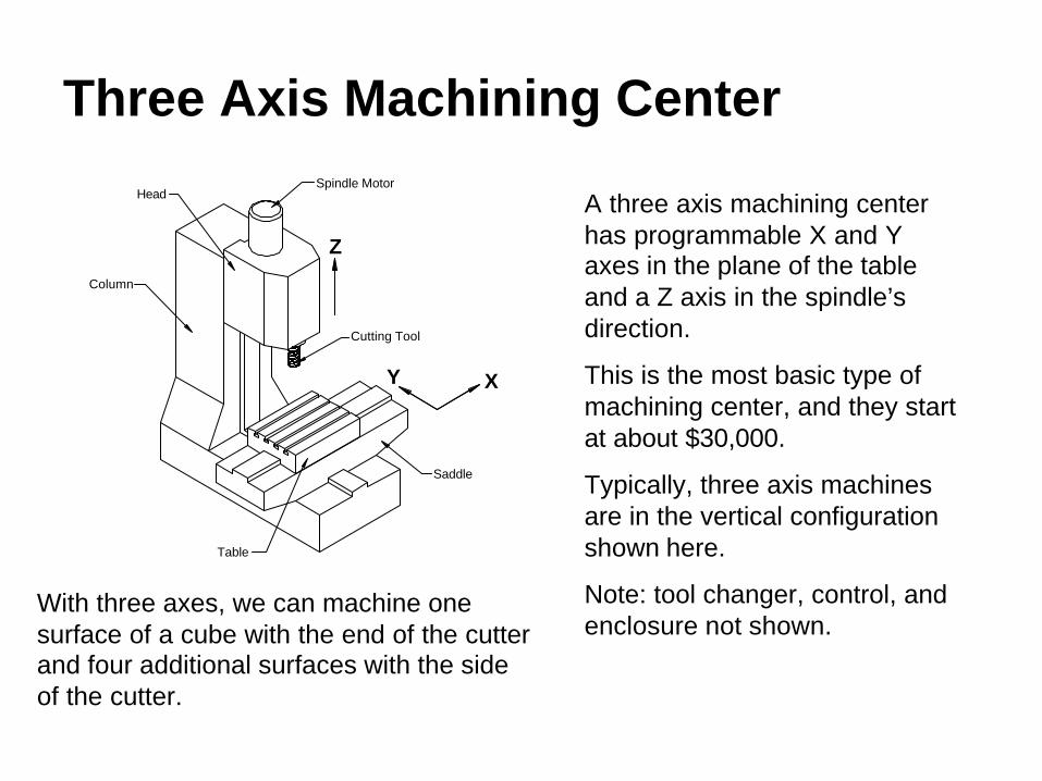
A three axis machining center has programmable X and Y axes in the plane of the table and a Z axis in the spindle’s direction.
This is the most basic type of machining center, and they start at about $30,000.
Typically, three axis machines are in the vertical configuration shown here.
Note: tool changer, control, and enclosure not shown.
With three axes, we can machine one surface of a cube with the end of the cutter and four additional surfaces with the side of the cutter.

Horizontal Three Axis MachineColumn
Saddle
TableCutter
Spindle
Head
The illustration depicts a three axis horizontal machining center.
Note the different orientation of the X, Y, and Z axes.
This type of machine starts at about $90,000.
Again, the tool changer, control, and enclosure are not shown.
We can still only machine one surface of a cube with the end of the cutter and four additional surfaces with the side of the cutter.
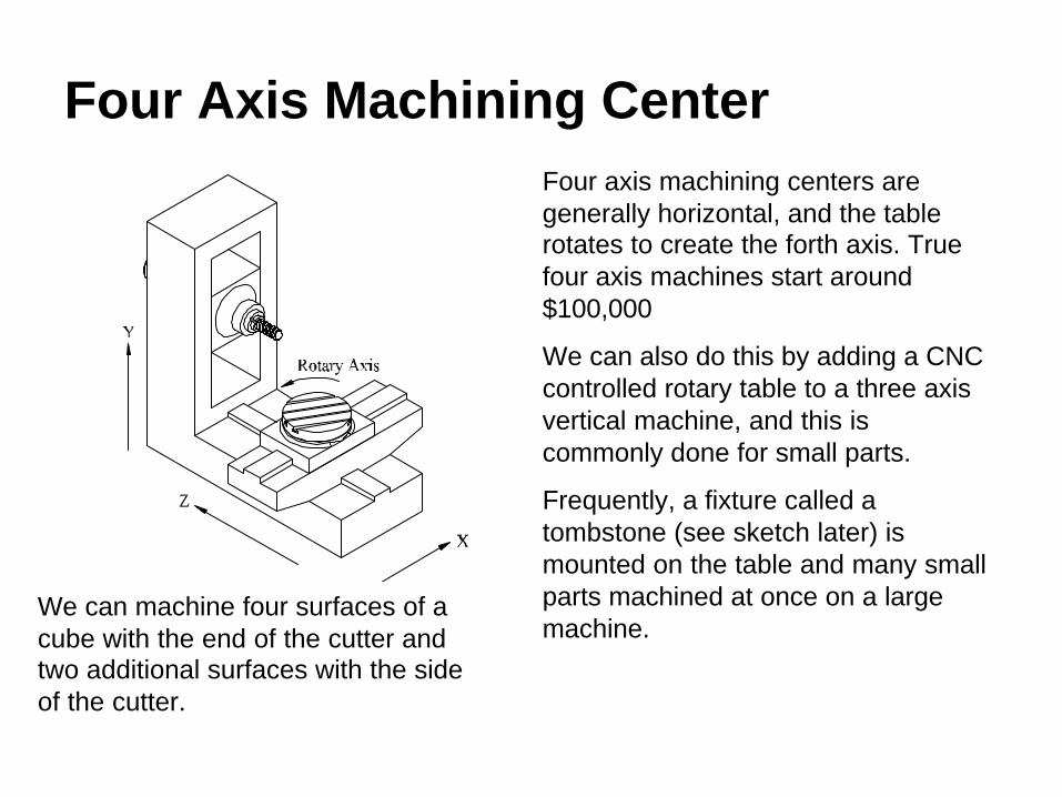
Four Axis Machining CenterFour axis machining centers are generally horizontal, and the table rotates to create the forth axis. True four axis machines start around $100,000
We can also do this by adding a CNC controlled rotary table to a three axis vertical machine, and this is commonly done for small parts.
Frequently, a fixture called a tombstone (see sketch later) is mounted on the table and many small parts machined at once on a large machine.
We can machine four surfaces of a cube with the end of the cutter and two additional surfaces with the side of the cutter.

Five Axis Machining Center
Be prepared to spend about $250,000 for a true five axis machine. Notice that it is very similar to the four axis machine except the spindle rotates from horizontal to vertical.
These machines are used to machine complex parts and molds in the aerospace and automotive industries.
We can machine five sides of a cube with the end of the cutter and six sides with the side of the cutter.
Besides complex geometry, we can often machine a part in one setup on a five axis machine that would require two or more setups in a simpler machine. This results in a more accurate part.

Machining Center with Pallet Changer
First Palletwith tombstone
in placefor machining.
Second pallet waitingto be swappedinto position.
Most machining centers can be fitted with a pallet changer to increase productivity.
On a plain machine, it sits idle while the operator removes the completed parts and loads the fixture with new ones.
With a pallet changer, the operator unloads and reloads one pallet while the machine works on the other. This way, the machine continuously cuts parts.

Machining Center Coordinate System
Work Coordina te Sys tem(WCS)
Mach ine Coord ina te Sys tem (MCS)at the center , end of the spindlewhen head is in i t s uppermost pos i t ion ,saddle is a l l the way towards the operator ,and the table i s a l l the way lef t .

The Haas VF-1
We will be using a Haas VF-1 three axis machining center with the following specifications: 20hp, 7500 RPM, 710ipm rapid, 300ipm feed, 20 CAT40 tools, 20”x16”x20” travel, 7100lbs!
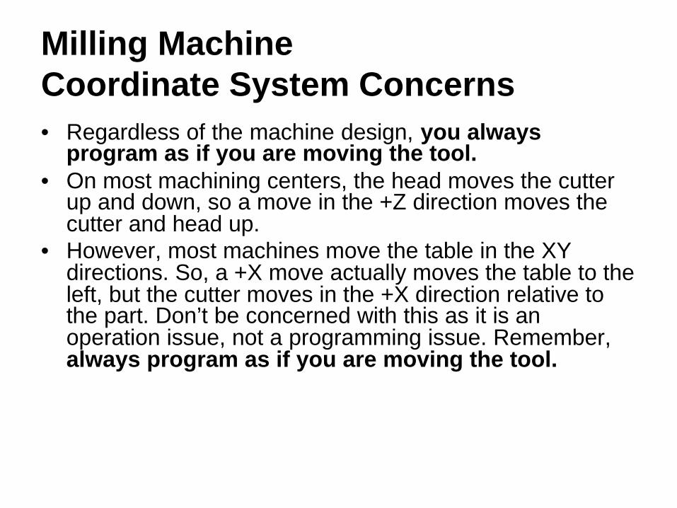
Milling Machine Coordinate System Concerns• Regardless of the machine design, you always
program as if you are moving the tool.• On most machining centers, the head moves the cutter
up and down, so a move in the +Z direction moves the cutter and head up.
• However, most machines move the table in the XY directions. So, a +X move actually moves the table to the left, but the cutter moves in the +X direction relative to the part. Don’t be concerned with this as it is an operation issue, not a programming issue. Remember, always program as if you are moving the tool.

Milling Machine CoordinateSystem Concerns (continued)• Read the Turning Centers Introduction if you have not
already done so.• As with the lathe, a fixture offset is entered into the
machine controller which includes the distance the machine moves from the MCS 0,0,0 to the WCS 0,0,0 position on the part.
• As with the lathe, the programmer picks the WCS on the part. This is more complicated because of the extra Y axis.
• The length of each tool is also entered into the machine control, so the machine compensates for the WCS and the length of the cutter.

Separating the Programmer from the Machine• As with the lathe, the programmer chooses the WCS on
the part, and then programs the cutter movement from there.
• The programmer calls the correct fixture offset and tool length offset numbers in the program (we’ll cover these codes later).
• So, once again, the programmer does not have to be too concerned with any machine specific measurements.

Incremental and Absolute Programming on Machining Centers
G91 G0 X3.Y2.X0.5
G90 G0 X3.Y2.0X3.5
G0 U3.W2.U0.5
G0 X3.Z2.X3.5
Notice that G90 signifies absolute coordinates and G91 signifies incremental, and both use X,Y,Z.
Notice the use of X,Z for absolute and U,W for incremental.
Incremental0,0,0 start
Absolute0,0,0 start
Incremental0,0 start
Absolute0,0 start
Machining CentersTurning Centers
Just as with turning centers, machining centers can be programmed with absolute or incremental coordinates, but machining centers use a different format:

Incremental vs. Absolute Programming• As with turning centers, most machining center
programming will be done in absolute mode.• Editing for program changes is much easier in absolute
mode, and absolute programs are much easier to follow.
• Certain repetitive operations such as drilling multiple holes lend themselves to incremental programming, and we will cover this later in the course.

Tooling for Machining Centers
CNC Applications

Cutting Tools
Most machining centers use some form of HSS or carbide insert endmillas the basic cutting tool.
Insert endmills cut many times faster than HSS, but the HSS endmills leave a better finish when side cutting.Photo courtesy ISCAR.

Cutting Tools (continued)
Facemills flatten large surfaces quickly and with an excellent finish. Notice the engine block being finished in one pass with a large cutter.Photo courtesy ISCAR.

Cutting Tools (continued)
Ball endmills (both HSS and insert) are used for a variety of profiling operations such as the mold shown in the picture.
Slitting and side cutters are used when deep, narrow slots must be cut.Photos courtesy ISCAR.

Milling Feed Direction
Remember, all CNC machines are equipped with ball screws to minimize slop when changing feed directions. The other advantage to ball screws is they allow climb milling instead of conventional milling as done on most manual machines.
Climb milling has many advantages including better surface finish, longer tool life, and the cutter deflects away from the work rather than into it.
Always climb mill on a CNC machining center!

Drills, Taps, and Reamers
Common HSS tools such as drills, taps, and reamers are commonly used on CNC machining centers. Note that a spot drill is used instead of a centerdrill. Also, spiral point or gun taps are used for through holes and spiral flute for blind holes. Rarely are hand taps used on a machining center.Drawings courtesy Precision Twist Drill.
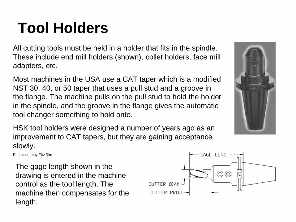
Tool HoldersAll cutting tools must be held in a holder that fits in the spindle. These include end mill holders (shown), collet holders, face mill adapters, etc.
Most machines in the USA use a CAT taper which is a modified NST 30, 40, or 50 taper that uses a pull stud and a groove in the flange. The machine pulls on the pull stud to hold the holder in the spindle, and the groove in the flange gives the automatictool changer something to hold onto.
HSK tool holders were designed a number of years ago as an improvement to CAT tapers, but they are gaining acceptance slowly.Photo courtesy Fitz-Rite
The gage length shown in the drawing is entered in the machine control as the tool length. The machine then compensates for the length.
Fixtures
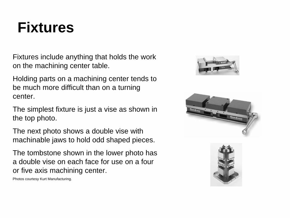
Fixtures include anything that holds the work on the machining center table.
Holding parts on a machining center tends to be much more difficult than on a turning center.
The simplest fixture is just a vise as shown in the top photo.
The next photo shows a double vise with machinable jaws to hold odd shaped pieces.
The tombstone shown in the lower photo has a double vise on each face for use on a four or five axis machining center.Photos courtesy Kurt Manufacturing.

More Fixtures
When parts can’t be held in a vise, a custom fixture must be used. Fixtures for high production parts are often custom designed and manufactured at great expense.
For small runs of odd-shaped parts, many manufacturers have turned to modular fixturing. As shown in the upper drawing, modular fixturing consists of many precision ground pieces that fit together to hold all sorts of parts as shown in the lower photo.Drawing and photo courtesy Bluco.
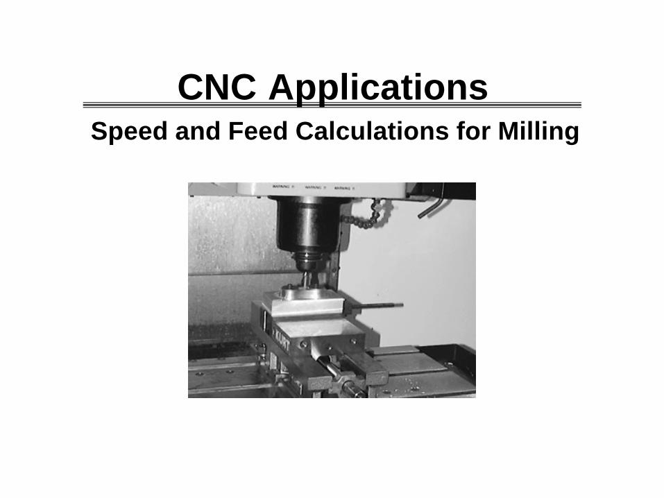
Speed and Feed Calculations for Milling
CNC Applications

Calculating RPM for Milling Operations with HSS Cutters
DV
RPMN××
==π12
We use the same basic formula as for turning, except D is now the cutter diameter:
Tables 10 through 16 list milling data. Table 6 must be used for copper alloys.

Example Milling RPM Calculation
• Mill 4140 steel with a Brinell hardness of 200 with a ½” HSS endmill.
• From Table 11, page 1047, we find V = 75 fpm, so:
5735.07512 =÷÷×= πRPM

Feed Rates for Milling• Feed for milling cutters is usually tabulated as inches per
tooth (ipt), but feed rates on milling machines are programmed in inches per minute (ipm). The equation on page 1041 in the Handbook is given as fm = ft nt N
• Where – fm is the feed rate in ipm we want to set the mill at.– ft is the feed rate in inches per tooth, ipt.– nt is the number of teeth on the cutter we are going to
use.– N is the RPM we already calculated.
• See Table 15a, pages 1054-1055, for values of f t with HSS cutters.

Example Milling Feed Rate Calculation
Mill 4140 steel with a Brinell hardness of 200 with a ½” 4 flute HSS endmill and a ¼” depth of cut.
We already calculated the RPM at 573,
From Table 15a, ft = 0.001“
fm = 0.001 x 4 x 573 = 2.3 IPM
Feed Rate Concerns
• Feed rates for facemill and slotting cutters vary widely.• Slow feed rates give a better finish, but sometimes this
actually dulls the cutter faster than a more rapid feed rate.
• Data for carbide insert milling cutters should be obtained from the insert manufacturer. Unlike lathe cutters which are fairly standard, milling cutters vary widely between manufacturers, so use your manufacturer’s data.
Calculating RPM for Drilling Operations with HSS Cutters
• The RPM formula for drilling is the same as for turning and milling, except D is now the drill diameter.
• Tables 17-23 lists data for drilling, reaming, and threading.
• Note: deeper holes require slower cutting speeds becausethe coolant cannot reach the cutting edge effectively.
• Feed rates for drilling are given in a paragraph on page1060. Note that the values are given in inches/revolution(ipr). If you need ipm, multiply ipr by RPM.

Drilling RPM and Feed Calculation Example• Drill cold drawn free cutting brass, C36000, with a 1”
drill. From Table 23, page 1072, we find V = 175 fpm, so:
• From page 1060, the feed would be between 0.007 and 0.015 ipr.
• To find ipm, use ipm = Feed x RPM = 0.015 x 668 = 10 ipm
668117512 =÷÷×= πRPM

Programming Machining Centers
CNC Applications

Planning and Programming
Just as with the turning center, you must follow a series of steps to create a successful program:
1. Examine the part drawing thoroughly and get a rough idea of how you want to proceed.
2. Figure out how to hold the raw material so you can perform asmuch machining as possible in one setup.
3. Decide what cutters are necessary to perform the various operations. This is more critical on machining centers because the holder and fixture can interfere with the work.
4. Write down the exact sequence of operations necessary to machine the part, one cutter at a time.
5. Convert your sequence of operations into a program and simulate the program if possible.

G and M Codes
Just as with turning centers, machining centers have two basic types of codes:ØG codes also called preparatory codesq tell the machine what type of movement or function should
be performed. For example, rapid moves, linear feed moves, arc feed moves, thread cutting, etc.
ØM codes also called miscellaneous functionsq turn the spindle on and off, coolant on and off, etc.
We already noted the G90/G91 for absolute and incremental programming. Another code unique to machining centers is M6 – tool change.
Common Codes
Tool ChangeM6Abs./Incr. Programming
G90/G91
End of programM30Go homeG28
Coolant on/offM8/M9CCW arcG3
Program stopM0CW arcG2
Spindle offM5Linear feed moveG1
Spindle forward/Spindle
reverse
M3/M4Linear rapid traverse
positioning move
G0
ActionMiscellaneous M Function
ActionPreparatory G Code
Other Codes
Cancel hole cycle
G80 Spindle SpeedS
Tool Number, Length Offset
T, HFirst fixture offset
G54
Arc VectorsI, JIPR feed modeG99
Absolute position
X, Y, ZCancel nose radius
compensation
G40
Program number
OInchesG20
ActionOther FunctionsActionPreparatory G Code

Modal
• Most codes are still modal – they stay in effect until something changes them.
• We only program what changes, nothing extra. For example:
G1 Z-.8 F20.0G1 Y2.4 Z-0.8G0 Y2.4 Z0.1G0 Z0.1 Y-0.4
G1 Z-.8 F20.0Y2.4G0 Z0.1Y-0.4
Difficult to follow, and changes require considerable effort.
Easy to read and change!
Works, but poor stylePreferred

Notes on Machining Center G & M Codes• Most machines only allow one M code per block.
• The capital “Oh” for the program number is the only “Oh” in the program. All others are zeros (0). Be sure you do not mistype.
• Unlike the lathe, the tool code (T) is two digits, we’ll cover how to handle the length offset shortly.
• All alpha characters must be in uppercase.
• Don’t forget to put decimal points on all numbers except 0’s! Remember, the machine thinks X3 really is X0.0003.
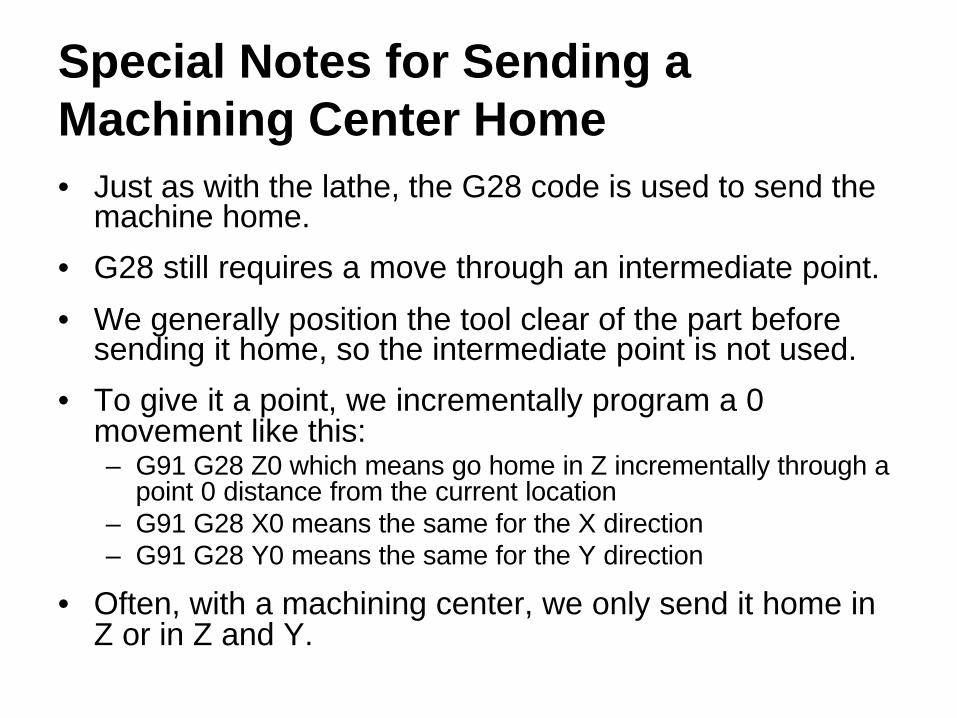
Special Notes for Sending a Machining Center Home• Just as with the lathe, the G28 code is used to send the
machine home.
• G28 still requires a move through an intermediate point.
• We generally position the tool clear of the part before sending it home, so the intermediate point is not used.
• To give it a point, we incrementally program a 0 movement like this:– G91 G28 Z0 which means go home in Z incrementally through a
point 0 distance from the current location– G91 G28 X0 means the same for the X direction– G91 G28 Y0 means the same for the Y direction
• Often, with a machining center, we only send it home in Z or in Z and Y.

Handling Tools on a Machining Center
Cancel length offsetG49
Offset number ttHtt
Load the length offsetG43
Do the tool changeM6
Call up tool number ttTtt
FunctionCode Changing tools is very machine specific, so be sure you know your machine!
Generally, the five codes shown in the table load the tool and the length offset as we’ll demonstrate on the next few slides.

Cutter Length Offset on a Machining Center (1)
Recall that in the Z direction, the MCS is at the end of the spindle, and the fixture offset measures the distance from the MCS to the WCS so the machine can compensate for the location of the part.
End of Spindlewith Drive Key
MCS 0
WCS 0
Z
X
Without length compensation, a move to Z0 on the part would bury the drive keys into the part causing a crash.
Workpiece

Cutter Length Offset on a Machining Center (2)
Length compensation subtracts the tool length from the distance between the MCS and WCS in the Z direction, so now the programmer is programming the center, end of the cutter.
WCS 0
Z
X
Tool Length
With Length Compensation,You are Programming this Point.
Now, a move to Z0 on the part brings the end of the cutter to the part.
Workpiece

Cutter Length Offset on a Machining Center (3)
With proper length compensation as shown, the programmer can safely program in the WCS with little regard to the cutter except to insure that the flutes are long enough and the toolholder does not interfere with the workpiece or with the fixture.
WCS 0
Z
X
Tool 3 in the Spindle
G0 G90 G43 H3 Z0Brings the cutter down to the top of the part.
Workpiece

Program Functions fall into just four (4) Categories1. Program Start2. Toolchange3. Program End4. Machining Functions
The first 3 are generally the same for all programs for a given machine.
Note that they will be different for different machines. You must know your machine by reading the machine manual!

Program Functions for the Haas VF-1 Machining Center• Remember, the CNC language is not 100% standard
across all machine and control manufacturers.• Haas machines use fairly generic programming that is
similar to most Fanuc compatible machines. Be especially careful of tool changes and sending the machine home!
• Again, you must know your machine by reading the machine manual!
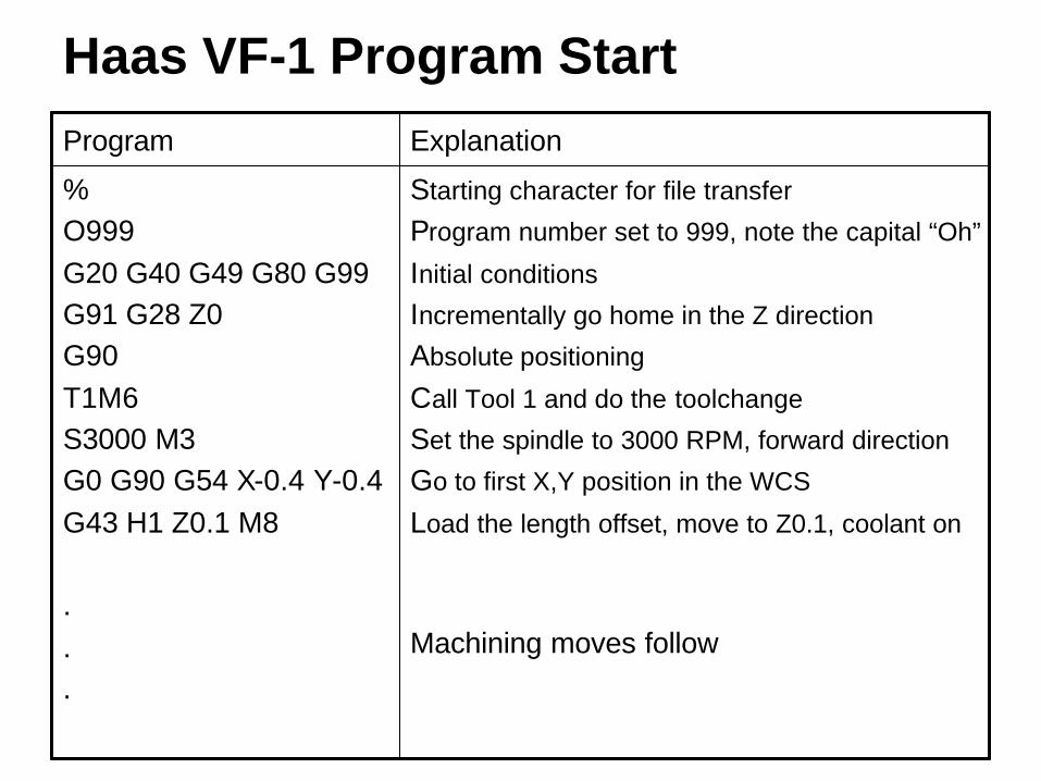
Haas VF-1 Program Start
Starting character for file transfer
Program number set to 999, note the capital “Oh”
Initial conditions
Incrementally go home in the Z direction
Absolute positioning
Call Tool 1 and do the toolchange
Set the spindle to 3000 RPM, forward direction
Go to first X,Y position in the WCS
Load the length offset, move to Z0.1, coolant on
Machining moves follow
%O999G20 G40 G49 G80 G99G91 G28 Z0G90T1M6S3000 M3G0 G90 G54 X-0.4 Y-0.4G43 H1 Z0.1 M8
.
.
.
ExplanationProgram
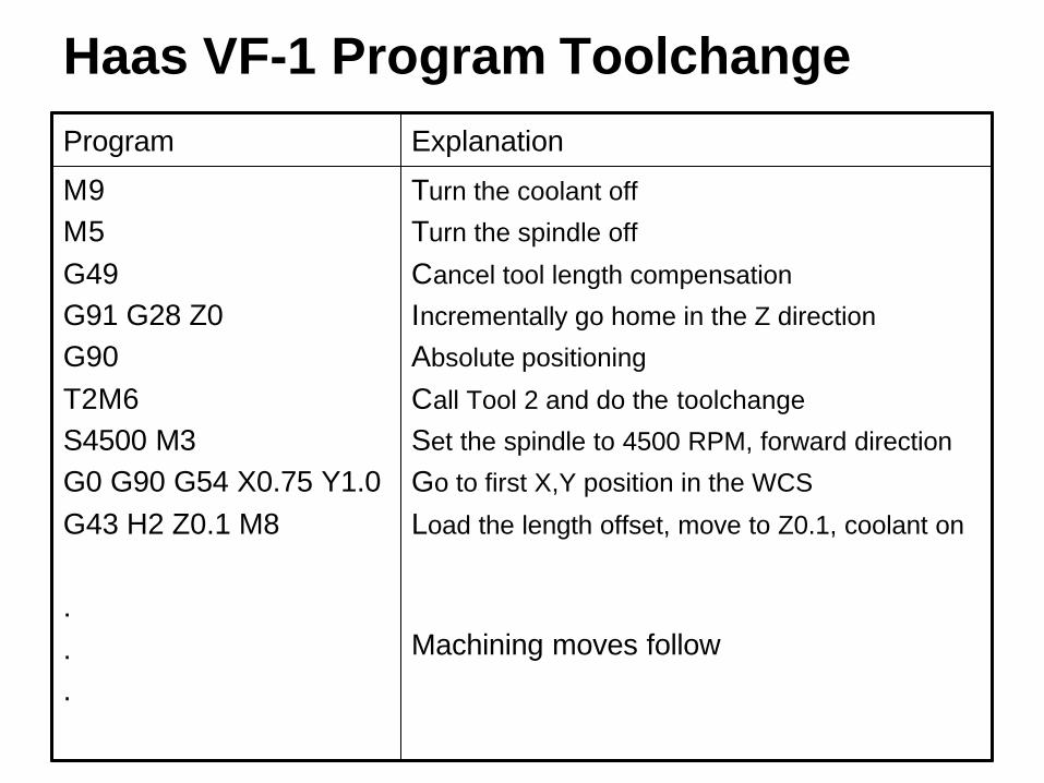
Haas VF-1 Program Toolchange
Turn the coolant off
Turn the spindle off
Cancel tool length compensation
Incrementally go home in the Z direction
Absolute positioning
Call Tool 2 and do the toolchange
Set the spindle to 4500 RPM, forward direction
Go to first X,Y position in the WCS
Load the length offset, move to Z0.1, coolant on
Machining moves follow
M9M5G49G91 G28 Z0G90T2M6S4500 M3G0 G90 G54 X0.75 Y1.0G43 H2 Z0.1 M8
.
.
.
ExplanationProgram

Haas VF-1 Program End
Turn the coolant off
Turn the spindle off
Cancel tool length compensation
Incrementally go home in the Z direction
Home in the Y direction to make unloading the part easier
Absolute positioning
End of program M code
End of file character for file transfer
M9M5G49G91 G28 Z0G28 Y0G90M30%
ExplanationProgram

Machining Center Example #1
CNC Applications

Problem Statement
0.700
3.000
2.000
Machine the length and thickness of the part shown below. The part is made from ¾”x2” 6061 CD aluminum which is saw cut to approximately 3 1/8” length. Perform all machining with a 2 flute, ¾” diameter, HSS endmillwhich is tool 1 on the machine.

Planning and Programming (1)
1. Examine the part drawing thoroughly and get a rough idea of how you want to proceed.
A. Pick the WCS in the lower left corner of the part on the finished upper surface:
B. Machine one end with the part against a stop.
C. Program stop, flip the part, and machine the 3” length.
D. Machine 0.050” off the top of the part leaving the final 0.700” thickness.

Planning and Programming (2-3)
2. How will we hold the part? In a 6” vise up on 1/8” wide parallels that hold the part only 3/8” into the vise jaws. A stop on the right positions the part.
3. Decide what cutters to use – given a ¾” diameter 2 flute HSS endmill. From the Machinery’s Handbook, we note that this endmill has 1 5/16” of useable flute length.
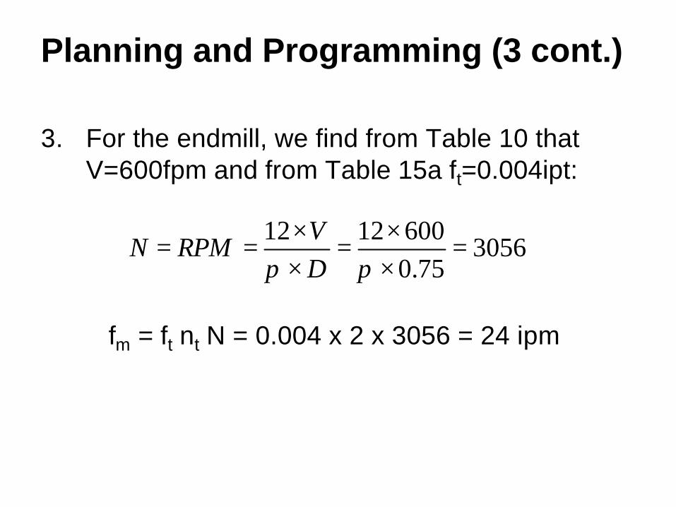
Planning and Programming (3 cont.)
3. For the endmill, we find from Table 10 that V=600fpm and from Table 15a ft=0.004ipt:
305675.0
6001212=
××
=××
==ππ D
VRPMN
fm = ft nt N = 0.004 x 2 x 3056 = 24 ipm
Planning and Programming (4)
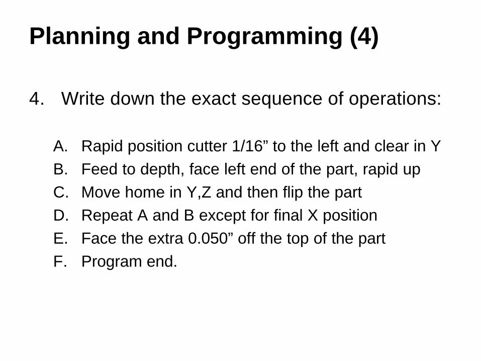
4. Write down the exact sequence of operations:
A. Rapid position cutter 1/16” to the left and clear in YB. Feed to depth, face left end of the part, rapid upC. Move home in Y,Z and then flip the partD. Repeat A and B except for final X positionE. Face the extra 0.050” off the top of the partF. Program end.
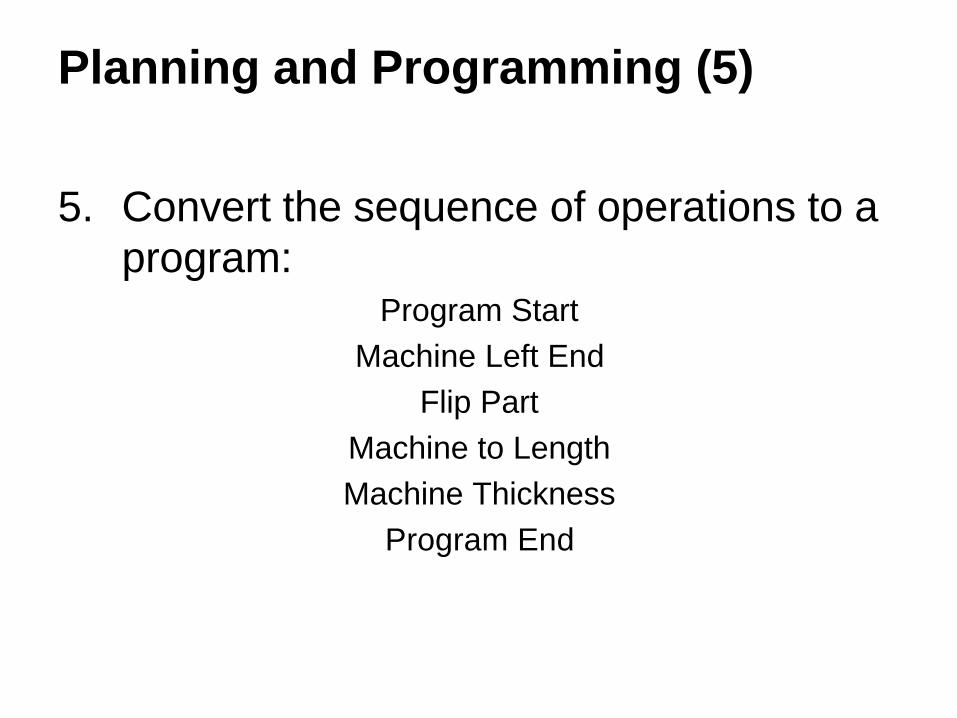
Planning and Programming (5)
5. Convert the sequence of operations to a program:
Program StartMachine Left End
Flip PartMachine to LengthMachine Thickness
Program End

An Overview of the Process
X
YZ
0.700
Excess Material from Saw Cut
0.050" Initial Clearance
0.050" Material to Remove
2.000
3.000
Notes:
1. Both ends of the part are saw cut. We will make one cut leaving 1/16” excess stock and then flip the part and remove the excess length.
2. We will initially position at Z0.1, but realize that we chose the Z=0 plane on the top of the FINISHED part, so we will only have 0.050” clearance as the detail view shows.
3. Remember, program as if the cutter moves in all 3 directions, even though the part moves in the X,Y directions.
4. Remember, we are programming the center of the cutter. All cuts must be offset by the cutter radius,

The First Portion of the Program
Program Start
Load tool 1, ¾” HSS endmillSet the spindle RPM and directionGo to initial position in the WCS using fixture offset G54Rapid to clearance with length compensation, coolant on
Start of Machining
Feed to depth – below part so a large burr is not leftCut the end of the part until clear in YRapid to clearance planeCoolant offSpindle offGo home in Z first to avoid hitting anything that sticks upThen, go home in YAbsolute positioning again to cancel the G91Program stop
%O999G20 G40 G49 G80 G99G91 G28 Z0G90T1 M6S3056 M3G0 G90 G54 X-0.437 Y-0.4G43 H1 Z0.1 M8
G1 Z-0.8 F24.Y2.1G0 Z0.1M9M5G91 G28 Z0G28 Y0G90M0
ActionProgram Codes
What the Machine Does
Select this link to start the animation.
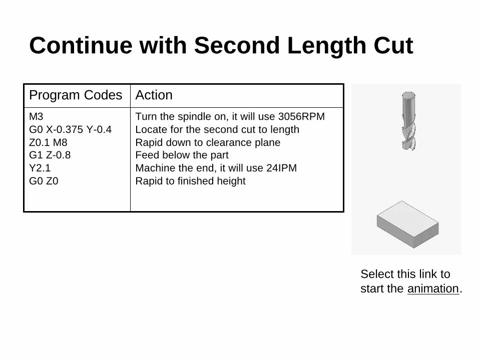
Continue with Second Length Cut
Turn the spindle on, it will use 3056RPMLocate for the second cut to lengthRapid down to clearance planeFeed below the partMachine the end, it will use 24IPMRapid to finished height
M3G0 X-0.375 Y-0.4Z0.1 M8G1 Z-0.8Y2.1G0 Z0
ActionProgram Codes
Select this link to start the animation.

Face the Top
Position for first passRepeat passes
.
.
.
Coolant offSpindle offCancel length compensationGo home in Z firstThen go home in YAbsolute modeEnd of programEnd of file
Y1.75G1 X3.4G0 Y1.125G1 X-0.4G0 Y0.5G1 X3.4G0 Y0G1 X-0.4M9M5G49G91 G28 Z0G28 Y0G90M30%
ActionProgram Codes
Select this link toStart the animation.

Constant Cutting Speed (CSS) for Turning Centers
CNC Applications
Constant Cutting Speed (CSS)
DV
RPMN××
==π12
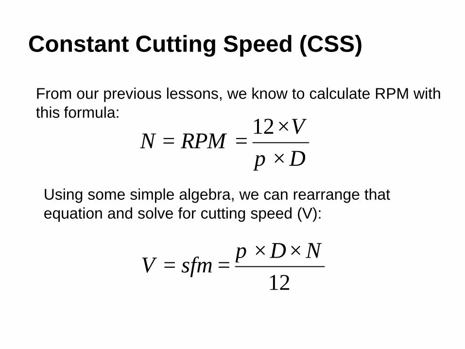
From our previous lessons, we know to calculate RPM with this formula:
12ND
sfmV××
==π
Using some simple algebra, we can rearrange that equation and solve for cutting speed (V):

Compare Cutting Speed when Facing
RPMN 5734
60012=
××
=π
We’ll face a 4” diameter part starting with V=600fpm. We calculate RPM as:
Now, we’ll work backwards and calculate the cutting speed (V) at the maximum diameter and towards the center at 0.25” diameter given a constant RPM=573.
fpmV 60012
5734=
××=
πfpmV 5.37
1257325.0
=××
=π

What does this mean?
• Any particular cutting speed is valid at only one RPM and diameter.
• As we decrease diameter at a constant RPM, cutting speed falls until it is zero when the cutter is at the part centerline.
• This decrease in cutting speed results in poor surface finish and shorter cutter life since hard cutters generally perform better at higher cutting speeds.
How do we fix the problem?
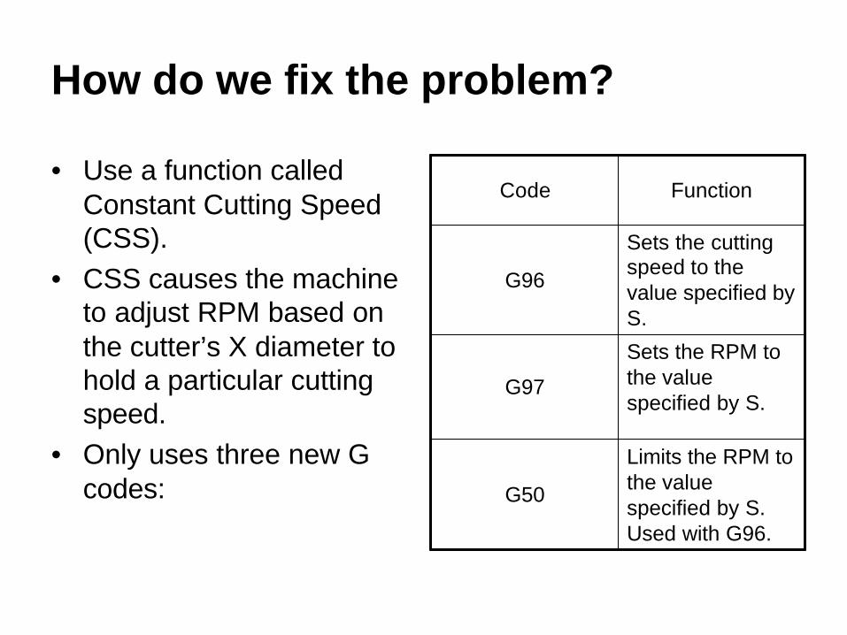
• Use a function called Constant Cutting Speed (CSS).
• CSS causes the machine to adjust RPM based on the cutter’s X diameter to hold a particular cutting speed.
• Only uses three new G codes:
Limits the RPM to the value specified by S. Used with G96.
G50
Sets the RPM to the value specified by S.
G97
Sets the cutting speed to the value specified by S.
G96
FunctionCode

A Sample CSS Program
Program Start
Limit the RPM to 4000 (slightly less than the machine max).Change to CSS, 600 fpm, machine sets RPM based on cutter position.
Machining
Set the RPM to 1800 constant (won’t change with cutter position).
More machining
Change to CSS, 600 fpm (modal), machine sets RPM.
% O999G20 G40 G99 G28 U0 G28 W0T0202 G54G50 S4000G96 S600 M3
.
.
.G97 S1800
.
.
.G96
ActionProgram Codes
CSS Comments
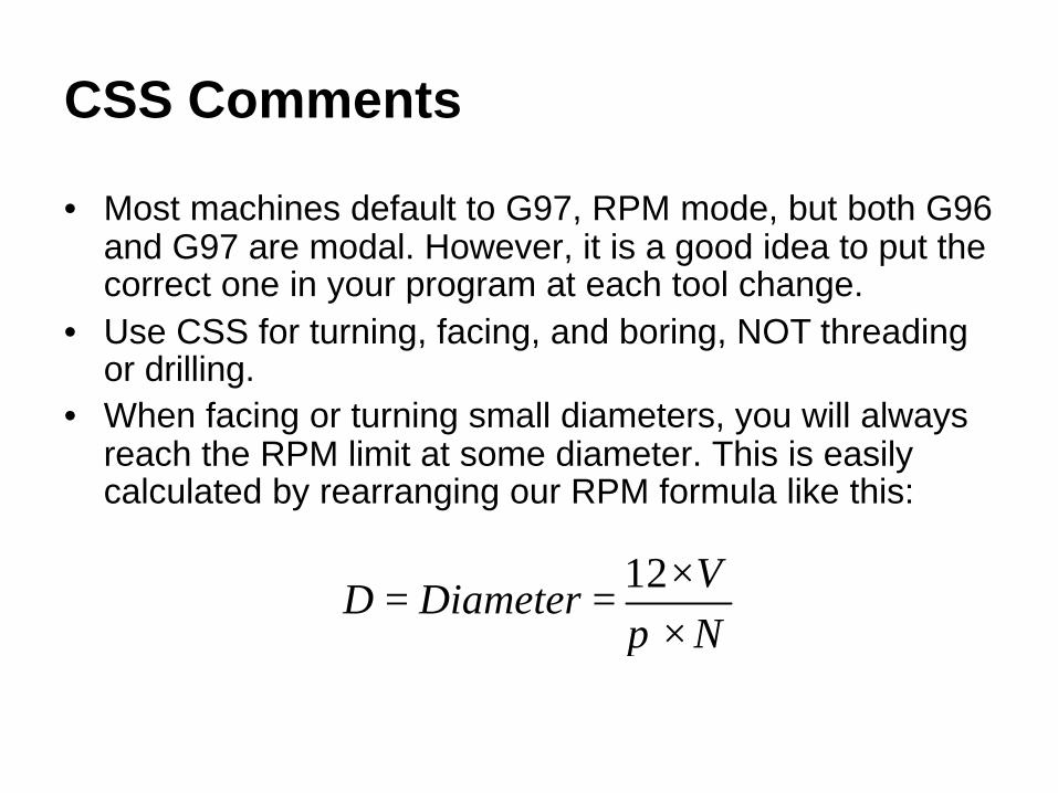
• Most machines default to G97, RPM mode, but both G96 and G97 are modal. However, it is a good idea to put the correct one in your program at each tool change.
• Use CSS for turning, facing, and boring, NOT threading or drilling.
• When facing or turning small diameters, you will always reach the RPM limit at some diameter. This is easily calculated by rearranging our RPM formula like this:
NV
DiameterD××
==π12

Example of Cutting Speed –Diameter Limit
From our previous program, we used 600 fpm. At an RPM limit of 4000RPM and 600fpm cutting speed, we can calculate the diameter as:
"573.040006001212
=××
=××
==ππ N
VDiameterD
So, any X value less than 0.573” means the cutting speed will be less than 600fpm with the corresponding poorer surface finish and shorter cutter life.

Rectangular Cycles for Turning Centers
CNC Applications
A Common Task
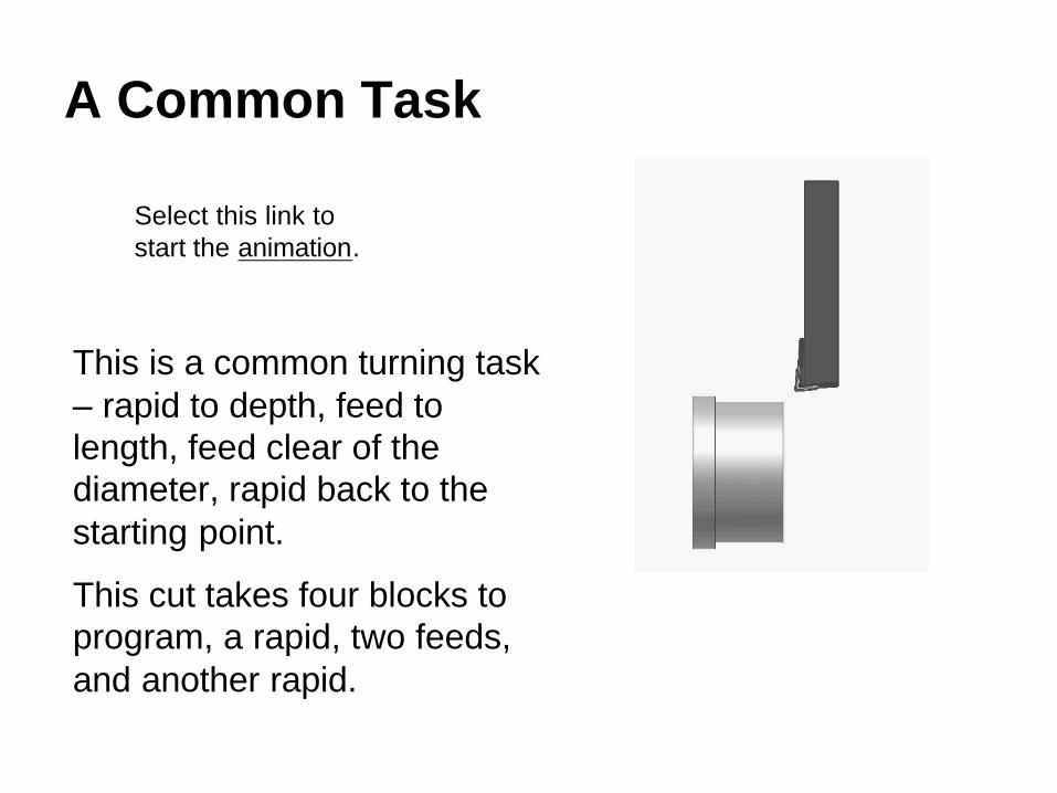
This is a common turning task – rapid to depth, feed to length, feed clear of the diameter, rapid back to the starting point.
This cut takes four blocks to program, a rapid, two feeds, and another rapid.
Select this link tostart the animation.

What is a Cycle?
• Normally, we only perform one positioning or cutting task in each block.
• However, tasks such as the four block turning sequence just provided are so common that control designers have incorporated CYCLES to reduce programming time.
• A cycle combines multiple moves into a single programmed block.

The Rectangular Turning Cycle
To use the rectangular turning cycle, you must first position the cutter at the Cycle Start Point. The cutter will also end up at the cycle start point at the end of the cycle. The program looks like this:
G90 Xnewx Znewz Fnewf
The cutter rapids to the newx diameter, feeds to the newz length, feeds to the starting X value, and then rapids back to the starting Z value. You get four blocks for just one programmed!
2
3
4
1
CycleStartPoint
New XPosition
New ZPosition

Additional G90 Notes
• The rectangular turning cycle (G90) is modal which is handy for repeat cuts.
• You can change newx and newz in succeeding cuts, and you can add a feed rate on any cut or just use the previous one.
• G90 only works in the direction shown. There are additional cycles for facing, boring, and turning towards the tailstock.
• What does G90 do on a machining center? (Hint: it has nothing to do with cycles.)

A G90 Turning Example
Ø4.000
0.500
1.5002.250
Ø3.000 Ø3.500
We will turn the 3.000” and 3.500” diameter steps on this part at 800fpm using the 80 degree C shaped insert in tool 2.

Follow Planning and Programming Steps (1-5)1. Examine drawing2. How will we hold the raw material – in a 3 jaw chuck.3. Decide what cutters to use – given hard, coated carbide C shaped
insert, and the cutting speed is also given (800fpm). We’ll use constant cutting speed (css) and let the machine calculate and adjust the RPM based on the X position of the cutter.
4. Write down the exact sequence of operations:A. Rapid position the cutter in Z 0.25” away from the face.B. Rapid position the cutter 0.125” away from the part in X (radial).C. Take 0.125” radial cuts (0.25” from diameter) using the G90 turning
cycle. Note: we are not taking finishing cuts in this example.D. Program end.
5. Convert the sequence of operations to a program:Program StartTurn the StepsProgram End
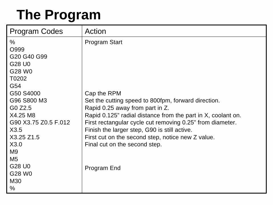
The Program
Program Start
Cap the RPMSet the cutting speed to 800fpm, forward direction.Rapid 0.25 away from part in Z.Rapid 0.125” radial distance from the part in X, coolant on.First rectangular cycle cut removing 0.25” from diameter.Finish the larger step, G90 is still active.First cut on the second step, notice new Z value.Final cut on the second step.
Program End
% O999G20 G40 G99 G28 U0 G28 W0T0202 G54G50 S4000 G96 S800 M3 G0 Z2.5X4.25 M8G90 X3.75 Z0.5 F.012X3.5X3.25 Z1.5X3.0M9 M5 G28 U0 G28 W0 M30 %
ActionProgram Codes

The Animation
Remember, the animation does not show the difference between rapid and feed moves. When actually run on the machine, the rapid moves are much faster than the feed moves.
Select this link tostart the animation.
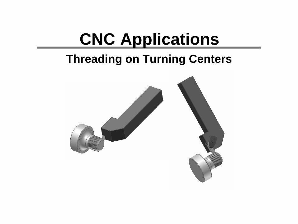
Threading on Turning Centers
CNC Applications
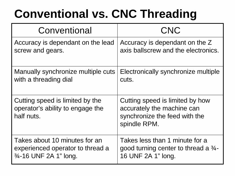
Conventional vs. CNC Threading
Takes less than 1 minute for a good turning center to thread a ¾-16 UNF 2A 1” long.
Takes about 10 minutes for an experienced operator to thread a ¾-16 UNF 2A 1” long.
Cutting speed is limited by how accurately the machine can synchronize the feed with the spindle RPM.
Cutting speed is limited by the operator’s ability to engage the half nuts.
Electronically synchronize multiple cuts.
Manually synchronize multiple cuts with a threading dial
Accuracy is dependant on the Z axis ballscrew and the electronics.
Accuracy is dependant on the lead screw and gears.
CNCConventional
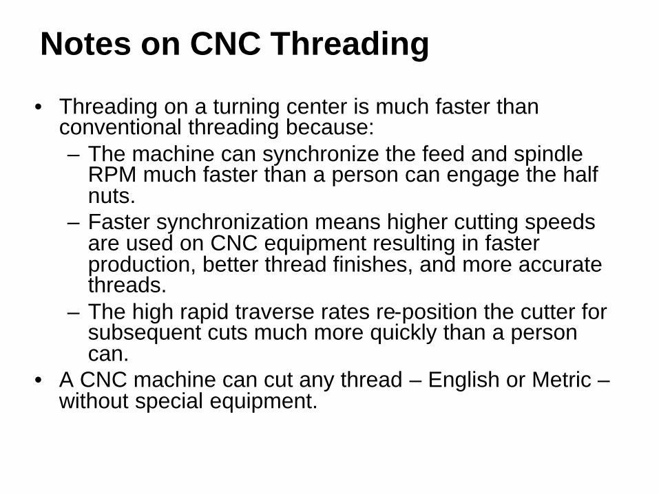
Notes on CNC Threading
• Threading on a turning center is much faster than conventional threading because:– The machine can synchronize the feed and spindle
RPM much faster than a person can engage the half nuts.
– Faster synchronization means higher cutting speeds are used on CNC equipment resulting in faster production, better thread finishes, and more accurate threads.
– The high rapid traverse rates re-position the cutter for subsequent cuts much more quickly than a person can.
• A CNC machine can cut any thread – English or Metric –without special equipment.

Threading Tool Offsets
Tool offset at thetip of the cutter.Be careful when threadingnear shoulders.
Tool offset at theside of the cutter.
You might have to adjust Zto get enough threads.
You can set the tool offset for a threading tool at the tip or at the side. The X value is the same in either case, only the Z value differs. As noted below, setting at the side helps prevent running into shoulders but may not have enough threads, while setting at the tip gives the correct thread length with increased risk of hitting a shoulder. Be aware of the method being used.

Insuring Thread Accuracy
0.1 Clearance
Enough room to synchronize.
While CNC machines are fast, they are not infallible. You must have enough clearance between the end of the part and the cutter’s start point for the feed motors to synchronize with the spindle. Most machine manuals have a formula for this distance which depends on RPM and thread pitch.
If you cut a thread that has the correct pitch diameter but still won’t fit a GO gage, increase this distance.
Be sure you have enough room to move around a live center or tailstock if one is being used!

Right Hand or Left Hand?
Right Hand Thread – spindle is going forward (M3) and the cut is towards the headstock.
Left Hand Thread – spindle is going reverse (M4) and the cut is towards the headstock.
To complicate things further, we can reverse the spindle rotations, cutter hands, and cut directions shown above and end up with the same thing. However, the two pictures shown above are the most common methods of threading, so be sure you understand them.
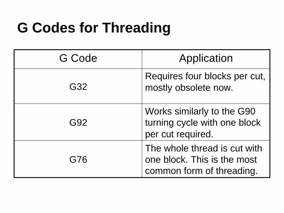
G Codes for Threading
The whole thread is cut with one block. This is the most common form of threading.
G76
Works similarly to the G90 turning cycle with one block per cut required.
G92
Requires four blocks per cut, mostly obsolete now.G32
ApplicationG Code

A Threading Example
3/4-16 UNF 2A
1.000
2.000
We’ll do this program twice –once with G92 and again with G76. In both cases, we’ll assume that the profile is already turned, and we will do the threading at 400fpm.

2
3
4
1
CycleStartPoint
New XPosition
New ZPosition
The G92 Rectangular Threading Cycle
G92 works the same as G90 except for the synchronization between spindle and cutter to create the threads. Start the cutter at the Cycle Start Point. The cutter will also end up at the cycle start point at the end of the cycle. Each block looks like this:
G92 Xnewx Znewz Flead
Note that lead is actual pitch calculated as 1/tpi for single start threads. Also, many turning centers use E instead of F on threading cycles. Know your machine!

Follow Planning and Programming Steps (1-3)1. Examine the drawing. We have to find some data from
the Machinery’s Handbook for a ¾-16 UNF 2A thread:• Major Diameter Range: 0.7391-0.7485”• Minor Diameter (Maximum): 0.674”• Lead = Pitch = 1/tpi = 1/16 = 0.0625”
2. How will we hold the raw material – in a collet chuck.3. Decide what cutters to use – given a tough, coated
carbide threading insert, and the cutting speed is also given (400fpm). We have to calculate the RPM since CSS should not be used when threading:
203775.0
4001212=
××
=××
==ππ D
VRPMN

Follow Planning and Programming Steps (4-5)4. Write down the exact sequence of operations:
A. Rapid position the cutter in Z 0.25” away from the face.B. Rapid position the cutter 0.1” away from the part in X (radial).C. Based on the Machinery’s Handbook data, we’ll assume the blank is
0.745” diameter to start, and we’ll take 6 passes at the following X values:
0.725 0.7050.690 0.6800.677 0.674
D. Program end.5. Convert the sequence of operations to a program:
Program StartMake the Threading Passes
Program EndNote: on our machine, the threading tool offset is taken from the side, not the point, of the cutter, so our threads will be somewhat short which we can adjust for in the program if we need to.

The Program with G92
Program Start
Load the threading tool
Set the RPM, forward direction.Rapid 0.25 away from part in Z.Rapid 0.1” radial distance from the part in X, coolant on.First threading cycle cut removing 0.020” from diameter.Second threading cut, G92 is still active.
Final threading cut, just a light pass.
Program End
% O999G20 G40 G99 G28 U0 G28 W0T0505 G54G97 S2037 M3 G0 Z2.25X0.945 M8G92 X0.720 Z1.0 F0.0625X0.705X0.690X0.680X0.677X0.674M9 M5 G28 U0 G28 W0 M30 %
ActionProgram Codes

Threading Animation
Note: the animation does not show the cutter moving to the start point or to home after machining the thread. It only shows the G92 cycle blocks.
Again, this is just an animation. The machine would cut the thread much faster than the animation shows.
Select this link tostart the animation.

G76 Threading Cycle
Cutting threads is so common, the CNC designers have created the G76 cycle to cut the entire thread in one pass. The format looks like this:
G76 Xrootx Zendz Itaper Kheight Dpass1 Flead Aangle
Where: rootx = minor diameter of the thread (required)endz = the ending Z value of the thread (required)taper = amount of taper when cutting a tapered thread (optional)height = radial height of the thread (required)pass1 = depth of the first pass (Note, most machines do not
allow a decimal point on D, so an integer must beused.) (required)
lead = pitch for a single start thread which is 1/tpi (required)angle = angle to enter the thread (optional)

General Comments about G76
• If you leave I off, the cycle produces a straight thread which is most common.
• If you leave A off, the cutter feeds straight in (see the next two slides for a more detailed description of A).
• The cycle works for both ID and OD threads based on the cycle start point and the values of X and Z.
• The cycle automatically decides how many passes to take depending on the value of K and D. Each pass is smaller than the previous pass.
• Some machines have more control over the number of passes and the depth of the final pass. Know your machine!
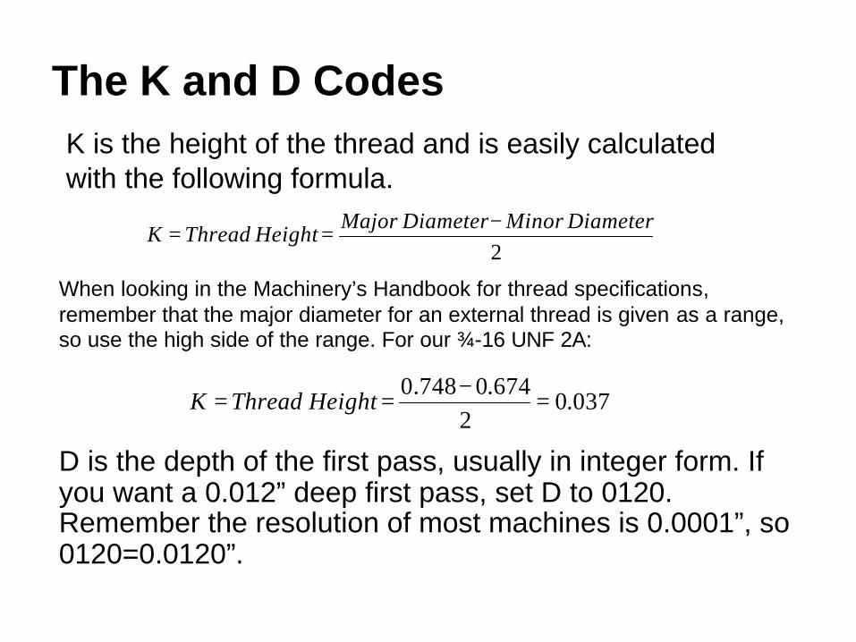
The K and D Codes
2 DiameterMinorDiameterMajorHeightThreadK −==
K is the height of the thread and is easily calculated with the following formula.
D is the depth of the first pass, usually in integer form. If you want a 0.012” deep first pass, set D to 0120. Remember the resolution of most machines is 0.0001”, so 0120=0.0120”.
When looking in the Machinery’s Handbook for thread specifications, remember that the major diameter for an external thread is given as a range, so use the high side of the range. For our ¾-16 UNF 2A:
037.02
674.0748.0 =
−== HeightThreadK

Deciphering the A Code
Thread Included Angle1/2 of A
As shown in the diagram below, a thread has an included angle. The most common angles are 60o for both metric and inch V threads and 29o for ACME threads. By changing the value of A, we can change the infeed angle of the threading cutter. The infeed angle is always ½ the value of A specified in the G76 cycle.
Notes:
1. Some machines will not accept a decimal point on A!
2. Some machines limit A to common thread angles, others allow any value.

Threading Feed Angle
A0 A60A20A60 – the machine actually feeds at 30o, or down the trailing flank. All cutting takes place on the insert’s leading edge, which is easiest on the cutter. The trailing flank usually has a poor finish. This is how most conventional (manual) threading is done.
A0 – the default. The cutter feeds straight in, and the insert cuts equally on both flanks. This is hard on the cutter, but both flanks usually have a good finish.
A20 – the machine actually feeds at 10o. Most cutting takes place on the leading flank, but some takes place on the trailing flank. A good compromise since it is fairly easy on the cutter, leaves a good finish, and tends to minimize chatter.

The Program with G76
Program Start
Load the threading tool
Set the RPM, forward direction.Rapid 0.25 away from part in Z.Rapid 0.1” radial distance from the part.Cuts the entire thread in one block!
Program End
% O999G20 G40 G99 G28 U0 G28 W0T0505 G54G97 S2037 M3 G0 Z2.25X0.945 M8G76 X0.674 Z1.0 D0120 K0.037 A20 F0.0625M9 M5 G28 U0 G28 W0 M30 %
ActionProgram Codes

Then, we move the start point of the threading cycle over by the pitch (0.0625”) and cut another thread in between those we just cut like this:
For single start threads (the most common), the lead is equal to the pitch. Or, in threading terms, the amount of advancement for one turn is equal to the distance between the threads.
Occasionally, we have to cut multiple start threads where the lead is an even multiple of the pitch. For example, to cut a ¾-16 double lead thread, we would cut a ¾-8 thread half-way deep like this:
Cutting Multiple Lead Threads

Cutting a Double Lead Thread with G76
Program Start
Load the threading tool
Set the RPM, forward direction.Rapid 0.25 away from part in Z.Rapid 0.1” radial distance from the part.Cuts the first thread, note the lead.Re-position the starting point.Cut the second thread.
Program End
% O999G20 G40 G99 G28 U0 G28 W0T0505 G54G97 S2037 M3 G0 Z2.25X0.945 M8G76 X0.674 Z1.0 D0120 K0.037 A20 F0.125G0 Z2.3125G76 X0.674 Z1.0 D0120 K0.037 A20 F0.125
M9 M5 G28 U0 G28 W0 M30 %
ActionProgram Codes

Programming Arcs
CNC Applications

Why Program Arcs?
• Many components have radius features which require machining.
• Arc programming on turning centers eliminates the need for form tools and results in a better finish.
• For machining centers, we can easily cut arcs which would otherwise require a complicated setup on a rotary table.
• For machining centers, internal radii such as the corner of pockets always machine better with an arc move rather than depending on the cutter to leave the radius.
• We have much more flexibility in choosing cutters on both machining and turning centers.

Arc OverviewTo program an arc, you must know the coordinates of the following three points:
1. Arc Start Point
2. Arc End Point
3. Arc Center Point
Notes:
On machining centers, you are programming the center of the cutter, so you must account for the radius of the cutter.
The cutter must be tangent to the arc at the start point and at the end point.
G02 Clock Wise Arc
G03 Counter Clock Wise Arc
Cutter PathArc Start Point
Arc End PointArc Center Point
J
Cutter Path
Arc Start PointArc End Point
Arc Center PointI

General Format for Arc Blocks on Machining Centers
G2 Xendx Yendy Ivectorx Jvectory FnewfG3 Xendx Yendy Ivectorx Jvectory FnewfWhere:
endx,endy are the coordinates of the Arc End Point.vectorx,vectory are the X and Y distances from the ArcStart Point to the Arc Center Point.
newf is a new feed rate, if desired. If Fnewf is left off,the last active feedrate will be used (F is modal).Refer to the picture on the previous page for definitions.

I and J for Machining Centers
Many people have trouble understanding I and J when they are really quite simple. I and J are signed X,Y directions from the Arc Start Point to the Arc Center point.The illustration shows an arc of <90 degrees which has both I and J values. 0, 90, 180, and 270 degree arcs always have either I or J as zero.Note for this example that I is a positive number while J is a negative number.
I
J
Arc End PointArc Start Point
Arc Center Point
Programmed Path
Tangent Point
Tangent Point

I and J (continued)
Mathematically, you can calculate I and J as:
I = XArcCenterPoint-XArcStartPoint J= YArcCenterPoint-YArcStartPoint
You can describe I and J as:
I=Distance from the Arc Start Point to the Arc Center point in X
J=Distance from the Arc Start Point to the Arc Center point in Y
Notice the difference between the mathematical definition and the written description of I and J. You can use either method to find I and J, but be sure you get the sign correct!

An Example With NumbersWe’ll mill the programmed path with a 1” diameter (0.5” radius) cutter. After finding the coordinates of the three points as shown, we calculate I and J as:
I = 3.0 – 3.0 = 0
J = 3.0 – 4.5 = -1.5
And the program segment would look like this:
G0 X-0.75 Y4.5G1 Z-0.25X3G2 X4.5 Y3.0 J-1.5G1 Y-0.75
Note that G2 and G3 are modal. A common mistake is to forget a G1 when a linear move follows an arc as in this example.
4.000
4.000
R1.000
Arc Start Point(3.0, 4.5)
Arc End Point(4.5, 3.0)
Arc Center Point(3.0, 3.0)
Programmed Path
J-1.5

General Format for Arc Blocks on Turning Centers
G2 Xendx Zendz Ivectorx Kvectorz FnewfG3 Xendx Zendz Ivectorx Kvectorz FnewfWhere:
endx,endz are the coordinates of the Arc End Point.vectorx,vectorz are the X and z distances from the ArcStart Point to the Arc Center Point.
newf is a new feed rate, if desired. If Fnewf is left off, the last active feedrate will be used (F is modal).
Note the only difference from machining centers is Y and J are replaced with Z and K.
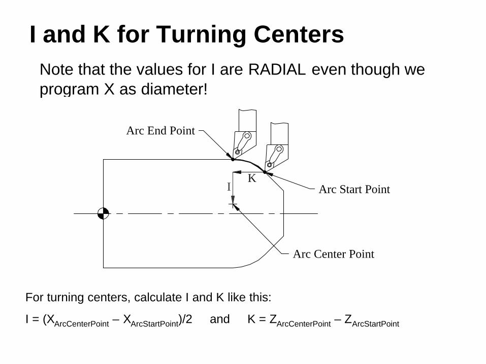
I and K for Turning CentersNote that the values for I are RADIAL even though we program X as diameter!
For turning centers, calculate I and K like this:
I = (XArcCenterPoint – XArcStartPoint)/2 and K = ZArcCenterPoint – ZArcStartPoint
KI
Arc Center Point
Arc Start Point
Arc End Point
Special Notes for Arcs on Turning Centers• Machining center arc programming must allow for the
radius of the cutter, turning center arc programming generally does not.
• The insert nose radius for a turning cutter does cause some inaccuracy in the arc formation which we will address later in the course.
• For now, ignore the insert nose radius and just remember it is a problem we will solve shortly.

A Turning Center Example
We’ll take a finish pass across the 1” diameter, the 0.750” radius, and the 2.5” diameter using a 55 degree (shape D) carbide insert cutter. Ø1.000
Ø2.500
1.000
3.000
R0.750

How the Machine Moves
Program Start
A. Rapid to position inZ and X, coolant
B. Feed to Arc Start C. Form arcD. Feed clear in Z
and X
% O999G20 G40 G99 G28 U0 G28 W0T0303 G54 S2800 M3 G0 Z3.25X1.0 M8G1 Z1.75 F.006G2 X2.5 Z1.0 I0.75G1 Z-0.25X2.75M9 M5 G28 U0 G28 W0 M30 %
ActionProgram Codes
I = (2.5 – 1.0)/2 = 0.75
K = 1.75 – 1.75 = 0
I0.75
Arc Start PointX=1.0, Z=1.75
Arc End PointX=2.5, Z=1.0
Arc Center PointX=2.5, Z=1.75
AB
CD
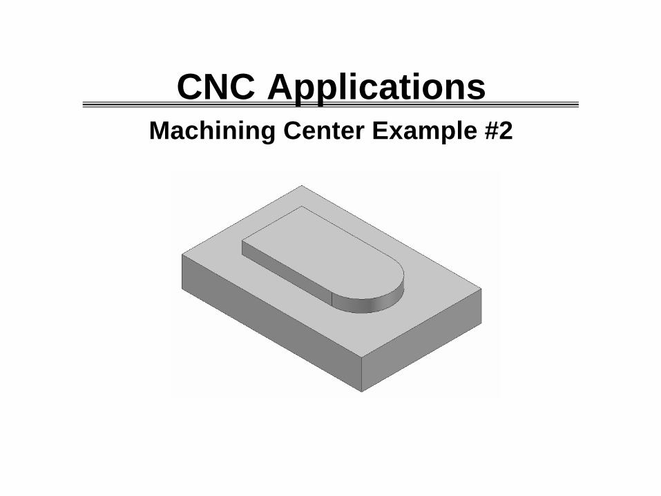
Machining Center Example #2
CNC Applications
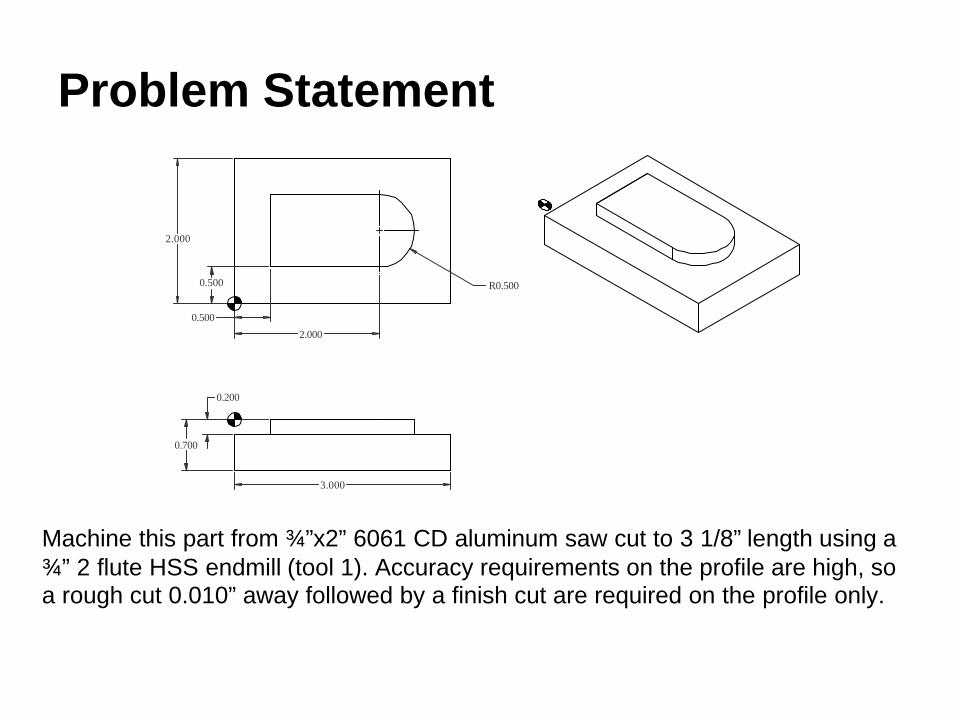
Problem Statement
3.000
0.200
0.700
0.500
2.000
R0.5000.500
2.000
Machine this part from ¾”x2” 6061 CD aluminum saw cut to 3 1/8” length using a ¾” 2 flute HSS endmill (tool 1). Accuracy requirements on the profile are high, so a rough cut 0.010” away followed by a finish cut are required on the profile only.

Planning and Programming (1)
1. Examine the part drawing thoroughly and get a rough idea of how you want to proceed.
A. Pick the WCS in the lower left corner of the part on the finished upper surface before machining the profile:
B. Machine one end with the part against a stop.
C. Program stop, flip the part, and machine the 3” length.
D. Machine 0.050” off the top of the part leaving the final 0.700” thickness.
E. Rough and finish the profile.F. Remove remaining “tails” in the
corners.

Planning and Programming (2-3)
2. How will we hold the part? In a 6” vise up on 1/8” wide parallels that hold the part only 3/8” into the vise jaws. A stop on the right positions the part.
3. Decide what cutters to use – given a ¾” diameter 2 flute HSS endmill. From the Machinery’s Handbook, we note that this endmill has 1 5/16” of useable flute length.

Planning and Programming (3 continued)
3. For the endmill, we find from Table 10 that V=600fpm and from Table 15a ft=0.004ipt:
305675.0
6001212=
××
=××
==ππ D
VRPMN
fm = ft nt N = 0.004 x 2 x 3056 = 24 ipm

Planning and Programming (4)
4. Write down the exact sequence of operations:
A. Rapid position cutter 1/16” to the left and clear in YB. Feed to depth, face left end of the part, rapid upC. Move home in Y,Z and then flip the partD. Repeat A and B except for final X positionE. Face the extra 0.050” off the top of the partF. Rough machine the profile leaving 0.010”.G. Finish machine the profile.H. Machine off excess material left in the corners nearest the
radius.I. Program end.

Planning and Programming (5)
5. Convert the sequence of operations to a program:
Program StartMachine Left End
Flip PartMachine to LengthMachine Thickness
Rough ProfileFinish Profile
Machine CornersProgram End

Don’t Redo Work
• Notice that the machine-to-length and machine-to-thickness operations required for this part are exactly the same as in Machining Center Example 1.
• We will simply copy the first program and add additional blocks to create this program.
• This is easily done by doing “Save As” in Notepad or other editor and then adding to the new file.
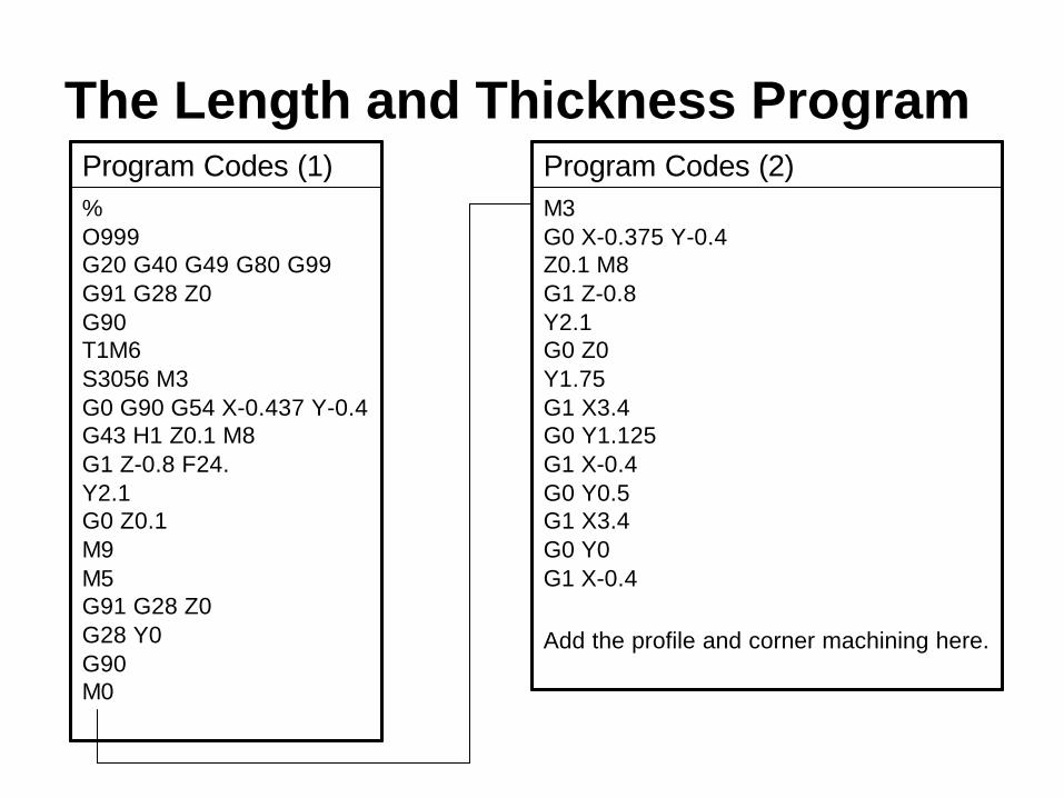
The Length and Thickness Program
%O999G20 G40 G49 G80 G99G91 G28 Z0G90T1M6S3056 M3G0 G90 G54 X-0.437 Y-0.4G43 H1 Z0.1 M8G1 Z-0.8 F24.Y2.1G0 Z0.1M9M5G91 G28 Z0G28 Y0G90M0
Program Codes (1)M3G0 X-0.375 Y-0.4Z0.1 M8G1 Z-0.8Y2.1G0 Z0Y1.75G1 X3.4G0 Y1.125G1 X-0.4G0 Y0.5G1 X3.4G0 Y0G1 X-0.4
Add the profile and corner machining here.
Program Codes (2)
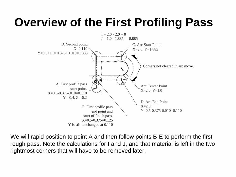
Overview of the First Profiling Pass
Corners not cleared in arc move.
A. First profile passstart point.
X=0.5-0.375-.010=0.110Y=-0.4, Z=-0.2
B. Second point.X=0.110
Y=0.5+1.0+0.375+0.010=1.885
C. Arc Start Point.X=2.0, Y=1.885
Arc Center Point.X=2.0, Y=1.0
D. Arc End PointX=2.0Y=0.5-0.375-0.010=0.110
E. First profile passend point and
start of finish pass.X=0.5-0.375=0.125
Y is still unchanged at 0.110
I = 2.0 - 2.0 = 0J = 1.0 - 1.885 = -0.885
We will rapid position to point A and then follow points B-E to perform the first rough pass. Note the calculations for I and J, and that material is left in the two rightmost corners that will have to be removed later.

The Blocks for the First Profile Pass
.Position at point A.
.Feed to point B.Feed to point C.Machine arc to point D.Feed to point E.
G0 Y-0.4X0.110Z-0.2G1 Y1.885X2.0G2 Y0.110 J-0.885G1 X0.125
ActionProgram Codes
Select this link tostart the animation.

Overview of the Finish Profiling Pass
We will continue feeding without pause after the roughing pass to points F-H. Then, we will feed completely off the part to the left in preparation for machining the excess corner material. Notice that J has changed from the rough pass.
I = 2.0 - 2.0 = 0J = 1.0 - 1.875 = -0.875
E. First profile passend point and
start of finish pass.X=0.5-0.375=0.125
Y is still unchanged at 0.110
H. Arc End PointX=2.0Y=0.5-0.375=0.125
Arc Center Point.X=2.0, Y=1.0
G. Arc Start Point.X=2.0, Y=1.875
F. Second point.X=0.125
Y=0.5+1.0+0.375=1.875

The Blocks for the Finish Profile Pass
Feed to point F.Feed to point G.Arc to point H.Feed off the part.
Y1.875X 2.0G2 Y0.125 J-0.875G1 X-0.4
ActionProgram Codes
Select this link tostart the animation.

Overview of Machining Corners
After finishing the second profile pass, we’ll rapid up to Z0.25 to clear the part and then move over to point J. We will then go back down to Z-0.2 and feed across the corners. The program ends by lifting up and then going home in Z and Y.
I. End of finish profile pass.X = -0.4, Y = 0.125, Z = -0.2
J. Start point formachining corners.X = 3.0, Y = 2.4, Z = -0.2
K. End point formachining corners.X = 3.0, Y = -0.4, Z = -0.2
Must lift to Z0.25before making this move.
Machine the Corners
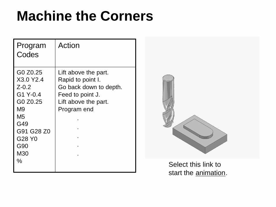
Lift above the part.Rapid to point I.Go back down to depth.Feed to point J.Lift above the part.Program end
.
.
.
.
.
G0 Z0.25X3.0 Y2.4Z-0.2G1 Y-0.4G0 Z0.25M9M5G49G91 G28 Z0G28 Y0G90M30%
ActionProgram Codes
Select this link tostart the animation.

The Final Program
G0 Z0.25X3.0 Y2.4Z-0.2G1 Y-0.4G0 Z0.25M9M5G49G91 G28 Z0G28 Y0G90M30%
M3G0 X-0.375 Y-0.4Z0.1 M8G1 Z-0.8Y2.1G0 Z0Y1.75G1 X3.4G0 Y1.125G1 X-0.4G0 Y0.5G1 X3.4G0 Y0G1 X-0.4G0 Y-0.4
X0.110Z-0.2G1 Y1.885X2.0G2 Y0.110 J-0.885G1 X0.125
%O999G20 G40 G49 G80 G99G91 G28 Z0G90T1M6S3056 M3G0 G90 G54 X-0.437 Y-0.4G43 H1 Z0.1 M8G1 Z-0.8 F24.Y2.1G0 Z0.1M9M5G91 G28 Z0G28 Y0G90M0
Program Codes

Hole Cycles
CNC Applications

Why so Many Hole Cycles?
• Creating holes is the most common machining operation since nearly all machined parts have at least one hole.
• Machining centers have many hole cycles including drilling, deep hole drilling, peck drilling, tapping, boring, etc.
• Turning centers usually have fewer hole cycles than machining centers, but they still have generally drilling, peck drilling, and tapping.
• Hole cycles for machining and turning centers are usually very similar.
Codes for Hole Cycles
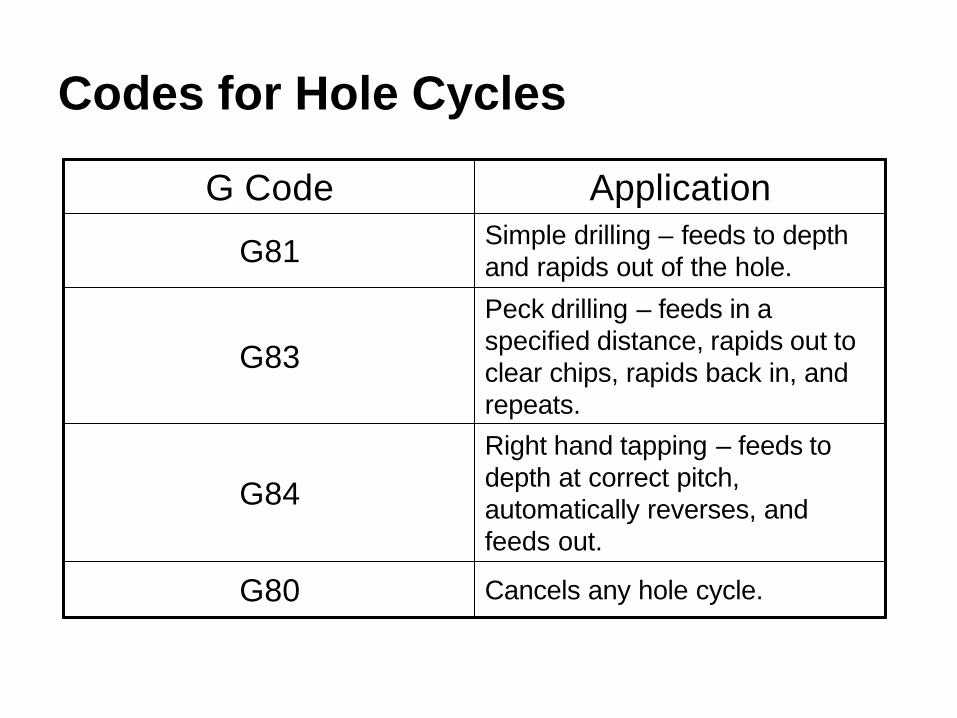
Cancels any hole cycle.G80
Right hand tapping – feeds to depth at correct pitch, automatically reverses, and feeds out.
G84
Peck drilling – feeds in a specified distance, rapids out to clear chips, rapids back in, and repeats.
G83
Simple drilling – feeds to depth and rapids out of the hole.G81
ApplicationG Code

A Simple Example
We will learn the basics of hole cycles by programming a machining center to create the holes in this part. We will start with spot drilling, continue with peck drilling, and finish with tapping.
1.000
3.000
1.000
3.000
1.000
4.000
4x Ø0.25 x 0.755/16-18 UNC - 2B x0.50w Ø0.50 X 90°

Planning and Programming (1)
1. Examine the part drawing thoroughly and get a rough idea of how you want to proceed.
A. Pick the WCS in the lower left corner of the part on the upper surface:
B. Assume length and thickness are already finished.
C. Spot drill all holes deep enough for the countersink.
D. Drill all the holes with a ¼” drill.
E. Tap all the holes with a spiral flute tap since the holes are blind.

Planning and Programming (2-3)
2. How will we hold the part? In a 6” vise up on 1/8” wide parallels. These thin parallels will not interfere with the holes, even if they went through the part. A stop on the right positions the part.
3. Decide what cutters to use – a 5/8” diameter spot drill (T12), a jobber’s length ¼” drill (T19), and a 5/16-18 spiral flute drill (T20).
Spot drill RPM = 12x600 / (p x0.625) = 3667 RPM¼” drill RPM = 12x600 / (p x0.25) = 9167 RPM, use 7000RPMTap RPM = choose 1500 RPM, machine will not tap at full RPM

Planning and Programming (4-5)4. Write down the exact sequence of operations:
A. Rapid cutters 0.1” above the part over the lower, left hole.
B. Perform the spot drilling, then do the other three holes.
C. Tool change, repeat A-B for the ¼” drill.D. Tool change, repeat A-B for the 5/16-18 tap.E. Program end.
5. Convert the sequence of operations to a program:Program Start
Spot Drill HolesPeck Drill Holes
Tap HolesProgram End

Spot DrillingWhen drilling holes on a machining center, a spot drill locates the hole prior to actual drilling. On conventional machines, centerdrillsare generally used for the same function, but the spot drill has three advantages over the centerdrill:
1. The spot drill does not have a small diameter point to break off and ruin the part.
2. By programming the spot depth carefully, we can generally eliminate countersinking.
3. Spot drills are commonly available with a 90o
point angle which generates a 45o chamfer, and other angles are available if desired.
The primary application of a centerdrill is to provide a location for a live center point when turning. People generally use them to spot holes, but spot drills work better.
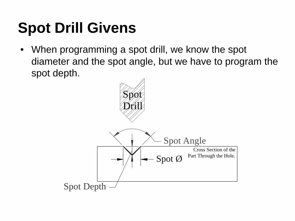
Spot Ø
Spot Depth
SpotDrill
Cross Section of the Part Through the Hole.
Spot Angle
Spot Drill Givens• When programming a spot drill, we know the spot
diameter and the spot angle, but we have to program the spot depth.

Calculating Spot Drill Depth
Spot Depth1/2 Spot Diameter
1. Spot
2. Split into 2 equal 45-45-90 triangles.
3. Look at one triangle:
Calculating spot depth with a 90o spot drill is quite easy as shown in these three steps. As you can see, spot depth is simply ½ of spot diameter.
Actually, your spot will be somewhat larger than calculated since spot drills are not ground to a sharp point. If your countersink has tight tolerances, you will have to adjust for it in the program.
Remember, Spot Depth = ½ Spot Diameter

The G81 Drilling CycleTo use the drilling cycle, follow these programming steps:1. Load the tool.2. Position over the first hole.3. Move to a Z distance above the part while turning on
tool length offset.4. Call the cycle with:
G81 Xnewx Ynewy Zdepth FfeedWhere newx and newy are the hole position, depth is the Z location at the bottom of the hole, and feed is the desired feed rate.

The G81 Drilling Cycle (continued)
5. Move to each succeeding hole and drill it.
Note: All hole cycles are modal, so only the X,Y location of the next hole is needed and the machine will move there and repeat the cycle.
G80 or G0 may be used to cancel the cycle.

The Spot Drilling Portion of the Program
Program Start
Load tool 12, 5/8” HSS spot drill.Set the spindle RPM and direction.Locate over the first hole in the WCS, set fixture offset.Rapid to clearance with length compensation, coolant on.Drill the hole. The cycle will retract to the initial Z0.1Move to the next hole and drill it, G81 is modal.Move to the next hole and drill it. Move to the next hole and drill it. Cancel the drilling cycle.
.The remainder of the program follows.
.
%O999G20 G40 G49 G80 G99G91 G28 Z0G90T12M6S3667 M3G0 G90 G54 X1.0 Y1.0G43 H12 Z0.1 M8G81 Z-0.25 F15.Y3.0X3.0Y1.0G80
.
.
.
ActionProgram Codes

Spot Drilling Animation
Note: The animation shows the spot drill in its initial position over the first hole and at the initial Z0.1 height. The animation ends at the G80.
Select this link tostart the animation.

Drilling Concerns• Prints generally give hole
depth to the full diameter and do not account for the drill point:
• We must program the depth to the point of the drill. We can calculate the additional depth as follows:
Print DepthProgrammed Depth
(180-Point Angle)/2
Drill Radius
Additional Depth
Radius Drill x 2
PointAngle180Depth Additional
−
= TAN
For our example with a 0.25” drill and a 118o point angle, the additional depth comes out to 0.075”

The G83 Peck Drilling CycleThis cycle works much the same as the G81 except for Q, the peck depth:G83 Xnewx Ynewy Zdepth Qpeckdepth Ffeed
Where newx and newy are the hole position, depth is the Z location at the bottom of the hole, peckdepth is the amount the drill feeds before backing out of the hole to clear chips, and feed is the desired feed rate.
For our example, we will use Q0.25, so it will make four pecks.

Look at G83 – Peck 1
First Pass 0.25 deep from the initial Z0.1, stops at Z-0.15, then rapids back out to Z0.1.

Look at G83 – Peck 2
Second Pass. Rapids just short of previous depth, feeds another 0.25 deep to Z-0.4, then rapids back out to Z0.1.

Look at G83 – Peck 3
Third Pass. Rapids just short of previous depth, feeds another 0.25 deep to Z-0.65, then rapids back out to Z0.1.

Look at G83 – Peck 4
Final Pass. Rapids just short of previous depth, feeds to final depth of Z-0.825, then rapids back out to Z0.1.
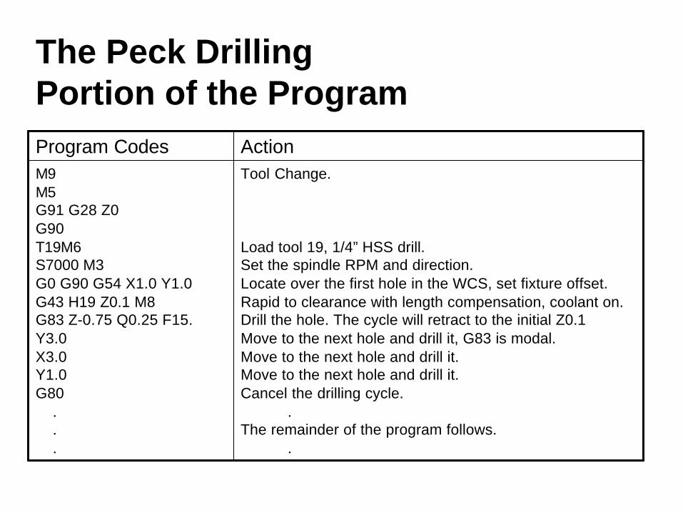
The Peck Drilling Portion of the Program
Tool Change.
Load tool 19, 1/4” HSS drill.Set the spindle RPM and direction.Locate over the first hole in the WCS, set fixture offset.Rapid to clearance with length compensation, coolant on.Drill the hole. The cycle will retract to the initial Z0.1Move to the next hole and drill it, G83 is modal.Move to the next hole and drill it. Move to the next hole and drill it. Cancel the drilling cycle.
.The remainder of the program follows.
.
M9M5G91 G28 Z0G90T19M6S7000 M3G0 G90 G54 X1.0 Y1.0G43 H19 Z0.1 M8G83 Z-0.75 Q0.25 F15.Y3.0X3.0Y1.0G80
.
.
.
ActionProgram Codes

Peck Drilling Animation
Note: The animation only shows drilling the first hole to save time. The program will then move the drill to the following holes and it will repeat the drilling cycle. The drill will stop over the last hole at the initial Z0.1 height.
Select this link tostart the animation.
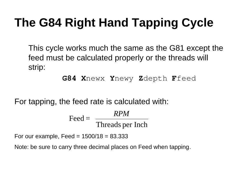
The G84 Right Hand Tapping Cycle
This cycle works much the same as the G81 except the feed must be calculated properly or the threads will strip:
G84 Xnewx Ynewy Zdepth Ffeed
For tapping, the feed rate is calculated with:
=
Inchper ThreadsFeed
RPM
For our example, Feed = 1500/18 = 83.333
Note: be sure to carry three decimal places on Feed when tapping.

Tapping Concerns
3-4 Threads Chamfered
Watch pointed taps!
Plug taps are the most common taps used on CNC equipment and they always have 3-4 threads chamfered. If the tap length is set for the end of the tap, this extra distance must be programmed. It is easy to calculate as:
Extra distance = 3/tpi
For our example, this comes to 0.167 which we will round to 0.17”.
Be careful of pointed taps! If the tap length is set from the point, then the program must account for this extra depth as well.
Always be sure the tap will not hit the hole bottom!

Tapping Portion of the Program
Tool Change.
Load tool 20, 5/16-18 tap.Set the spindle RPM and direction.Locate over the first hole in the WCS, set fixture offset.Rapid to clearance with length compensation, coolant on.Tap the hole. The cycle will retract to the initial Z0.1Move to the next hole and tap it, G84 is modal.Move to the next hole and tap it. Move to the next hole and tap it. Cancel the cycle.
.Program End.
.
M9M5G91 G28 Z0G90T20M6S1500 M3G0 G90 G54 X1.0 Y1.0G43 H19 Z0.1 M8G84 Z-0.67 F83.333Y3.0X3.0Y1.0G80M9M5G49
G91 G28 Z0G28 Y0G90M30%
ActionProgram Codes

Tapping Animation
Click here to start the animation.
Note: The animation shows the tap in its initial position over the first hole and at the initial Z0.1 height. The animation ends at the G80.
Note that the G84 cycle automatically reverses the spindle and feeds the tap out.
Select this link tostart the animation.

Hole with a Retract Plane
CNC Applications

A Common Problem
When drilling these holes, we have to stay clear of the boss, but we don’t want the drill to start feeding above the part.
There is an easy solution to this problem – use an R plane.
1.0002.000
1.500 1.000
1.0003.000
4.000
0.750
3.2504.000
5/16-18 UNC - 2B x0.50w Ø0.3 X 90°
4x Ø0.25 x 0.75
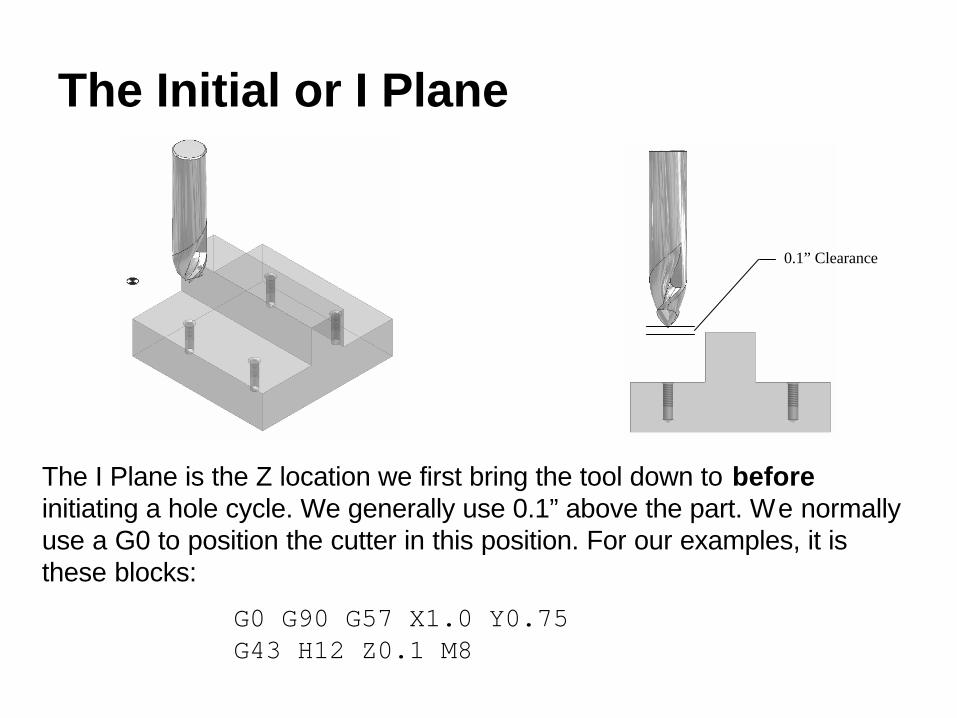
The Initial or I Plane
The I Plane is the Z location we first bring the tool down to beforeinitiating a hole cycle. We generally use 0.1” above the part. We normally use a G0 to position the cutter in this position. For our examples, it is these blocks:
G0 G90 G57 X1.0 Y0.75G43 H12 Z0.1 M8
0.1” Clearance
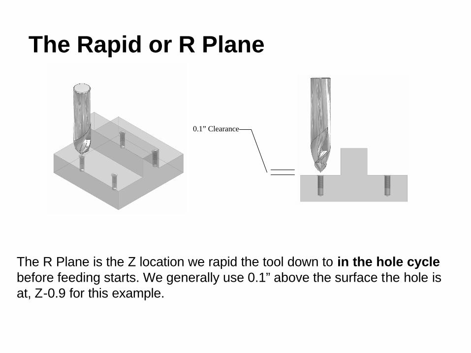
The Rapid or R Plane
The R Plane is the Z location we rapid the tool down to in the hole cyclebefore feeding starts. We generally use 0.1” above the surface the hole is at, Z-0.9 for this example.
0.1” Clearance

Programming the R PlaneTo add an R plane to any hole cycle, we just add R with the Z value to the cycle. For this example:
G81 Z-1.15 R-0.9 F15.
This works for all cycles as follows:
G83 Z-1.75 Q0.25 R-0.9 F15.
G84 Z-1.67 R-0.9 F83.333
The only problem is that holes on the same side of an obstruction cause wasted time because the cutter rapids up and down from the R plane. To solve this problem, we use G98 and G99.
After drilling this hole, return to the R plane. G99
After drilling this hole, return to the I plane. This is usually the default.G98
ApplicationG Code

The Spot Drilling Portion of the Program with R Plane
Program Start
Load tool 12, 5/8” HSS spot drillSet the spindle RPM and directionLocate over the first hole in the WCS, set fixture offset.Rapid to the I plane with length compensation, coolant onDrill the hole. The cycle will retract to the R plane Z=-0.9Drill the next hole, retract to I plane Z=0.1 to clear part.Retract to the R plane Z=-0.9 Retract to the I plane Z=-0.1 Cancel the drilling cycle.
.The remainder of the program follows.
.
%O999G20 G40 G49 G80 G99G91 G28 Z0G90T12M6S3667 M3G0 G90 G57 X1.0 Y0.75G43 H12 Z0.1 M8G81 Z-1.15 R-0.9 F15. G99X3.0 G98Y3.25 G99X1.0 G98G80
.
.
.
ActionProgram Codes

Spot Drilling Animation with R Plane
The animation starts with the spot drill at Z0.1 and ends with the G80. Notice how the drill only retracts to Z-0.9 between holes on the same side of the obstruction.
Select this link tostart the animation.
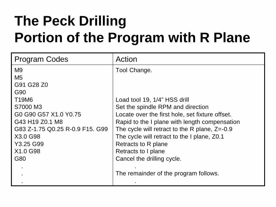
The Peck Drilling Portion of the Program with R Plane
Tool Change.
Load tool 19, 1/4” HSS drillSet the spindle RPM and directionLocate over the first hole, set fixture offset.Rapid to the I plane with length compensationThe cycle will retract to the R plane, Z=-0.9The cycle will retract to the I plane, Z0.1Retracts to R planeRetracts to I planeCancel the drilling cycle.
.The remainder of the program follows.
.
M9M5G91 G28 Z0G90T19M6S7000 M3G0 G90 G57 X1.0 Y0.75G43 H19 Z0.1 M8G83 Z-1.75 Q0.25 R-0.9 F15. G99X3.0 G98Y3.25 G99X1.0 G98G80
.
.
.
ActionProgram Codes

Tapping Portion of the Program
Tool Change.
Load tool 20, 5/16-18 tap.Set the spindle RPM and direction.Locate over the first hole in the WCS.Rapid to clearance with length compensation.Tap the hole. The cycle will retract to the R plane, Z-0.9Move to the next hole and tap it, retracts to I plane, Z0.1Retracts to R plane, Z-0.9 Retracts to I plane, Z0.1 Cancel the cycle.
.Program End.
.
M9M5G91 G28 Z0G90T20M6S1500 M3G0 G90 G57 X1.0 Y0.75G43 H19 Z0.1 M8G84 Z-1.67 R-0.9 F83.333 G99X3.0 G98Y3.25 G99X1.0 G98G80M9M5G49
G91 G28 Z0G28 Y0G90M30%
ActionProgram Codes

Tool Nose Radius Compensationon Turning Centers
CNC Applications

Facing and Straight Turning
• When facing or straight turning, the tool nose radius has no effect on the part other than leaving a radius on inside corners.
Theoretical sharp point is what we program.
This tangent point finishes diameters.
This tangent point finishes faces.

The ProblemWhen turning tapers or radii, the tool nose radius leaves excess material as shown here:
Excess Material Here

The Solution
1. Manually program the exact tangent points. This is time consuming since it requires trig calculations or accurate CAD drawings to locate the tangent points.
2. Use tool nose radius compensation. The tool nose radius is entered into the machine controller, and the program turns on compensation for finish cuts only, and then turns it off. The machine calculates the tangent points so we can continue programming as if the cutter has a sharp point.

Tool Nose Radius G Codes
Compensate for tool nose radius to the RIGHT of the programmed path.
G42
Compensate for tool nose radius to the LEFT of the programmed path.
G41
Cancel tool nose radius compensation.G40
ApplicationG Code
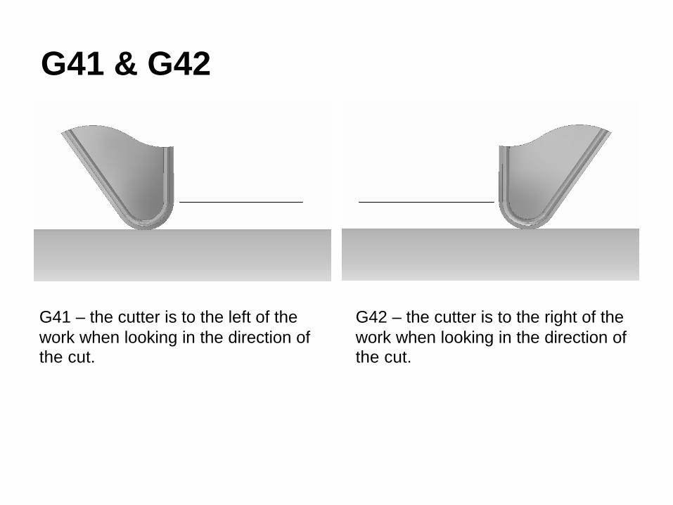
G41 & G42
G41 – the cutter is to the left of the work when looking in the direction of the cut.
G42 – the cutter is to the right of the work when looking in the direction of the cut.

Turning Nose Radius Compensation On
Start Point of Finish Passwith Compenation On,0.1 Away in Z.
Compensation Point, 0.1 AwayFrom Start Point in Z, 0.2 in X.
Turn Nose Radious Compensationon in This Move.
To turn compensation on, the machine must move at least the distance of the nose radius in X and Z. For easy calculations, back away from the start point 0.1 in Z and 0.2 in X. Remember X is diameter based, so 0.2 in X is actually 0.1 radially.

Turning Nose Radius Compensation Off
Feed Moves Clearof the Part.
Feed Move to TurnNose Radius Compensation Off.
To turn compensation off, we feed the cutter completely off the work and then make a move larger than the nose radius while calling G40.
Note: Do not reverse the Z direction with nose radius compensation on! The machine may get confused, and then later cuts may be off by some multiple of the nose radius. Always call G40 BEFORE reversing the Z direction!

A G42 Example
Ø2.500 Ø1.500
R0.375
0.2500.625
1.000
2.000
Ø1.750
0.25x45°
We will program ONLY the finish pass on this part using G42 right tool nose radius compensation. We are given 800fpm cutting speed and 0.006ipr feed.
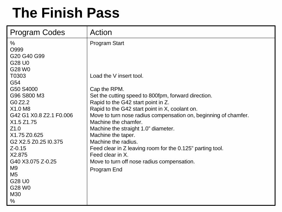
The Finish Pass
Program Start
Load the V insert tool.
Cap the RPM.Set the cutting speed to 800fpm, forward direction.Rapid to the G42 start point in Z.Rapid to the G42 start point in X, coolant on.Move to turn nose radius compensation on, beginning of chamfer.Machine the chamfer.Machine the straight 1.0” diameter.Machine the taper.Machine the radius.Feed clear in Z leaving room for the 0.125” parting tool.Feed clear in X.Move to turn off nose radius compensation.Program End
% O999G20 G40 G99 G28 U0 G28 W0T0303 G54G50 S4000G96 S800 M3 G0 Z2.2X1.0 M8G42 G1 X0.8 Z2.1 F0.006X1.5 Z1.75Z1.0X1.75 Z0.625G2 X2.5 Z0.25 I0.375 Z-0.15X2.875G40 X3.075 Z-0.25M9 M5 G28 U0 G28 W0 M30 %
ActionProgram Codes

The Final Pass
Select this link tostart the animation.

Tool Radius Compensationfor Machining Centers
CNC Applications

Why Cutter Diameter Compensation?• When machining finished surfaces with the side of a
milling cutter (generally called profiling), the accuracy of the finished surface depends on the cutter accuracy and how closely the cutter diameter matches the programmed size.
• Cutters wear causing size changes in profiled surfaces.• Reground endmills are always smaller than nominal size.
Note: this feature is also frequently called Cutter Radius Compensation. We use Diameter Compensation to avoid confusion with turning center operation.

How Does Cutter Diameter Compensation work?
• The programmer programs for a nominal size cutter (0.750” for our T1, for example) for rough cuts.
• The programmer calls cutter diameter compensation for THE FINISH PASS ONLY, and programs as if the cutter has zero diameter.
• The set-up person enters the nominal size in the machine controller.
• Parts are measured as they are manufactured, and the operator enters small deviations to keep the parts on size (generally called wear offsets). The machine automatically adjusts for the wear offsets.

Cutter Diameter Compensation Codes
tt is the tool number. D tells the controller where to find the cutter’s diameter.
Dtt
Compensate for the cutter to the RIGHT of the programmed path. G42
Compensate for the cutter to the LEFT of the programmed path. G41
Cancel cutter diameter compensation.G40
ApplicationCode
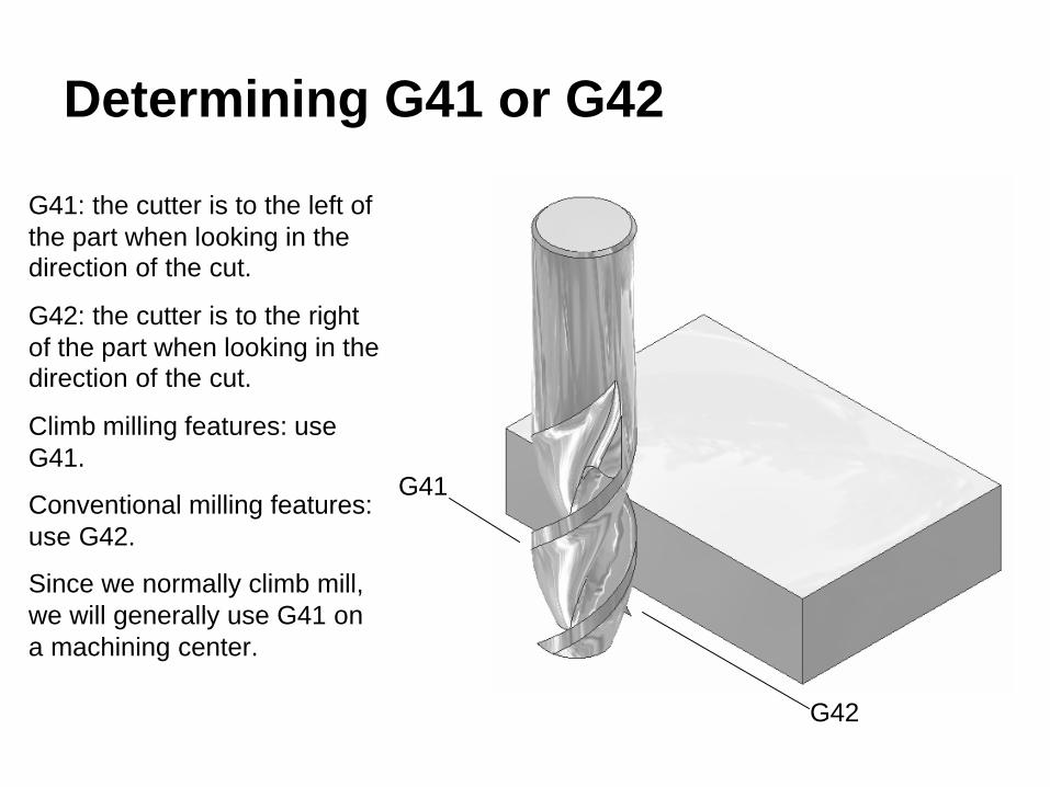
Determining G41 or G42
G41
G42
G41: the cutter is to the left of the part when looking in the direction of the cut.
G42: the cutter is to the right of the part when looking in the direction of the cut.
Climb milling features: use G41.
Conventional milling features: use G42.
Since we normally climb mill, we will generally use G41 on a machining center.

Turning Cutter Diameter Compensation On• Prior to compensation, you must take into account the
cutter’s radius and locate the cutter offset by its radius.• In the move turning compensation on, try to make the
move as perpendicular to the following move as possible, and try to turn compensation on with the cutter off the part. Note: the D code should be in the same block as the G41 or G42.
• The move to turn compensation on should be equal or greater than the cutter’s radius.
• Once compensation is on, ignore the cutter’s size and program as if the cutter has 0 diameter. This usually simplifies programming, especially arc programming.
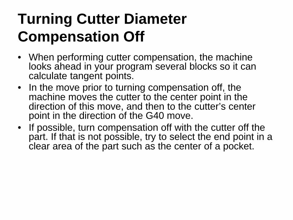
Turning Cutter Diameter Compensation Off• When performing cutter compensation, the machine
looks ahead in your program several blocks so it can calculate tangent points.
• In the move prior to turning compensation off, the machine moves the cutter to the center point in the direction of this move, and then to the cutter’s center point in the direction of the G40 move.
• If possible, turn compensation off with the cutter off the part. If that is not possible, try to select the end point in a clear area of the part such as the center of a pocket.

A Graphical Look at Cutter Diameter Compensation
Move to turn compensation off. Choose the destination point taking into account thatyou are now programming the center ofthe cutter.
In the move prior to the G40,the machine looks ahead and seesthat the next block contains the G40.Hence, it stops the center of the cutterat the coordinate given in this move.
Initial position of the cutter priorto the G41. You must program
the center of the cutter at this point.
Move to turn on compensation.It should be as perpendicularto the following move aspossible.
At the end of the G41 move, program as if the cutterhas 0 diameter. So, program the part size directly. Themachine offsets the cutter the correct amount.
Compensated moves. Program thepart dimensions directly ignoring the
cutter's size.
Part
Final position of the cutter.Compensation is off, programthe cutter's center.

A Compensation Example
0.375
1.6252.000
0.375
2.625
3.000
0.200
0.700
We’ll program this part with a ¾” endmill, T1. We’ll assume the length and thickness are already machined. So, we will take one roughing pass leaving 0.010” on the profile, and then we will finish the profile with tool diameter compensation.
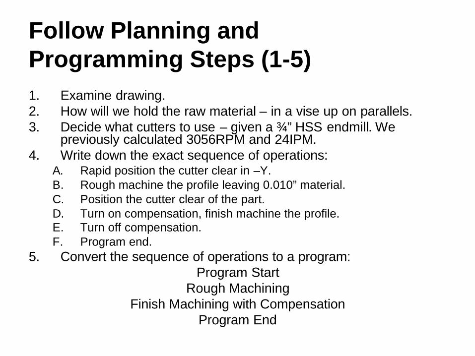
Follow Planning and Programming Steps (1-5)1. Examine drawing.2. How will we hold the raw material – in a vise up on parallels.3. Decide what cutters to use – given a ¾” HSS endmill. We
previously calculated 3056RPM and 24IPM.4. Write down the exact sequence of operations:
A. Rapid position the cutter clear in –Y.B. Rough machine the profile leaving 0.010” material.C. Position the cutter clear of the part.D. Turn on compensation, finish machine the profile.E. Turn off compensation.F. Program end.
5. Convert the sequence of operations to a program:Program Start
Rough MachiningFinish Machining with Compensation
Program End
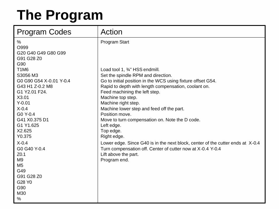
The Program
Program Start
Load tool 1, ¾” HSS endmill.Set the spindle RPM and direction.Go to initial position in the WCS using fixture offset G54.Rapid to depth with length compensation, coolant on.Feed machining the left step.Machine top step.Machine right step.Machine lower step and feed off the part.Position move.Move to turn compensation on. Note the D code.Left edge.Top edge.Right edge.Lower edge. Since G40 is in the next block, center of the cutter ends at X-0.4Turn compensation off. Center of cutter now at X-0.4 Y-0.4Lift above the part.Program end.
%O999G20 G40 G49 G80 G99G91 G28 Z0G90T1M6S3056 M3G0 G90 G54 X-0.01 Y-0.4G43 H1 Z-0.2 M8G1 Y2.01 F24.X3.01Y-0.01X-0.4G0 Y-0.4G41 X0.375 D1G1 Y1.625X2.625Y0.375X-0.4G0 G40 Y-0.4Z0.1M9M5G49G91 G28 Z0G28 Y0G90M30%
ActionProgram Codes

Program Animation
The animation starts with the cutter in its initial XY location and Z depth after the G43 line. The animation ends with the G0 Z0.1
Select this link tostart the animation.

Parting on Turning Centers
CNC Applications

The Parting Operation• Parting and grooving are very similar except parting
removes the part from the end of a bar while grooving adds a groove to the part’s profile.
• Parting of small parts can be done with a G1 to feed in and a G0 to rapid out.
• Larger parts should use the G75 parting cycle which pecks the cut so the chips break up.
• Be careful of parting parts completely off unless the machine has a parts catcher. Flying parts can damage tooling!
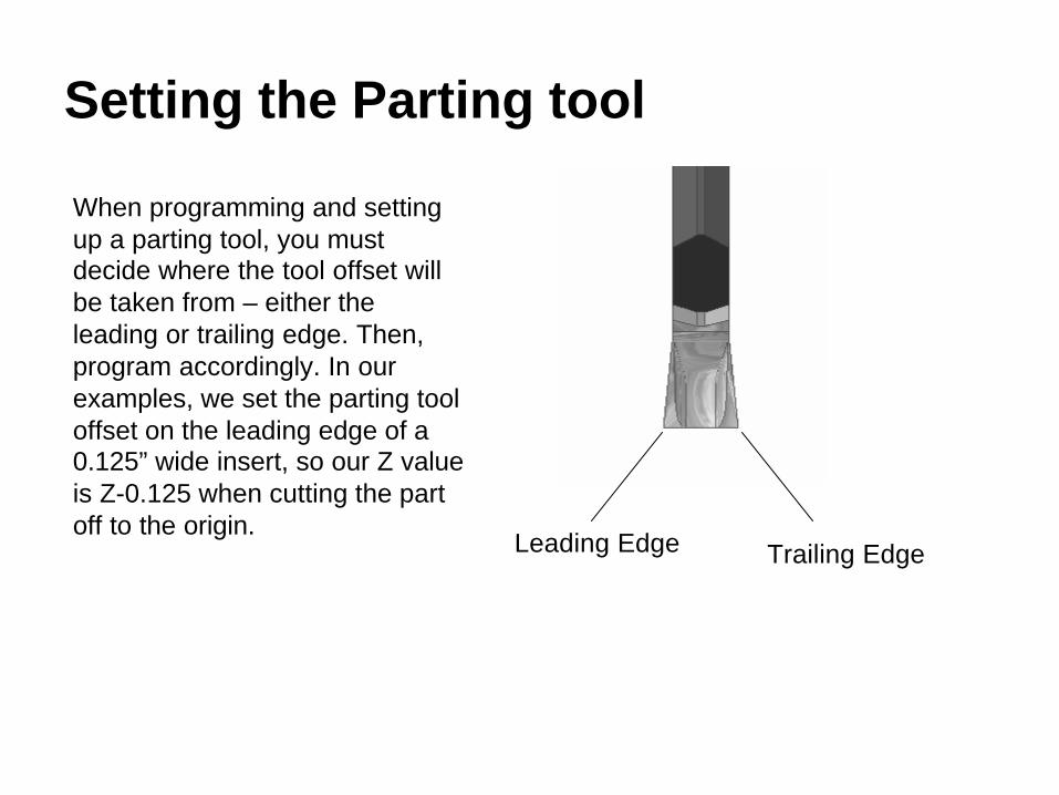
Setting the Parting tool
Trailing EdgeLeading Edge
When programming and setting up a parting tool, you must decide where the tool offset will be taken from – either the leading or trailing edge. Then, program accordingly. In our examples, we set the parting tool offset on the leading edge of a 0.125” wide insert, so our Z value is Z-0.125 when cutting the part off to the origin.
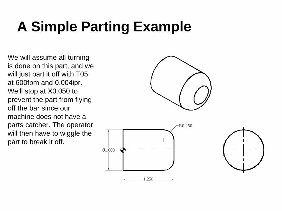
A Simple Parting Example
Ø1.000
1.250
R0.250
We will assume all turning is done on this part, and we will just part it off with T05 at 600fpm and 0.004ipr. We’ll stop at X0.050 to prevent the part from flying off the bar since our machine does not have a parts catcher. The operator will then have to wiggle the part to break it off.

Parting
Program Start
Load the parting tool.
Cap the RPM.Set the cutting speed to 600fpm, forward direction.Rapid to the starting point for parting in Zand in X.Feed in.Rapid out to the initial point.Program end.
% O999G20 G40 G99 G28 U0 G28 W0T0505 G54G50 S4000G96 S600 M3 G0 Z-0.125X1.1G1 X0.050 F0.004G0 X1.1M9 M5 G28 U0 G28 W0 M30 %
ActionProgram Codes

The G75 Parting CycleSmall parts may be parted off by simply feeding the cutter straight into the part and then rapiding away, but larger parts require the G75 peck cycle to break the chips up and prevent them from clogging the cutter. The format is as follows:
G75 Xendx Qpeckdepth FfeedWhere endx = X diameter at the bottom, generally 0 or slightly more than 0
peckdepth = how much to advance at a timefeed = feed rate for the parting cycle
Like all cycles, you must position the cutter at the cycle start point using G0 blocks. Then, at the end of the cycle, the cutter will return to its cycle start point.
The next program shows the parting cycle being used to cut off our same example part.

Parting with G75
Program Start
Load the parting tool.
Cap the RPM.Set the cutting speed to 600fpm, forward direction.Rapid to the cycle starting point for parting in Zand in X.Parting peck cycle with 0.25” pecks. Returns to X1.1Program end.
% O999G20 G40 G99 G28 U0 G28 W0T0505 G54G50 S4000G96 S600 M3 G0 Z-0.125X1.1G75 X0.050 Q0.25 F0.004M9 M5 G28 U0 G28 W0 M30 %
ActionProgram Codes
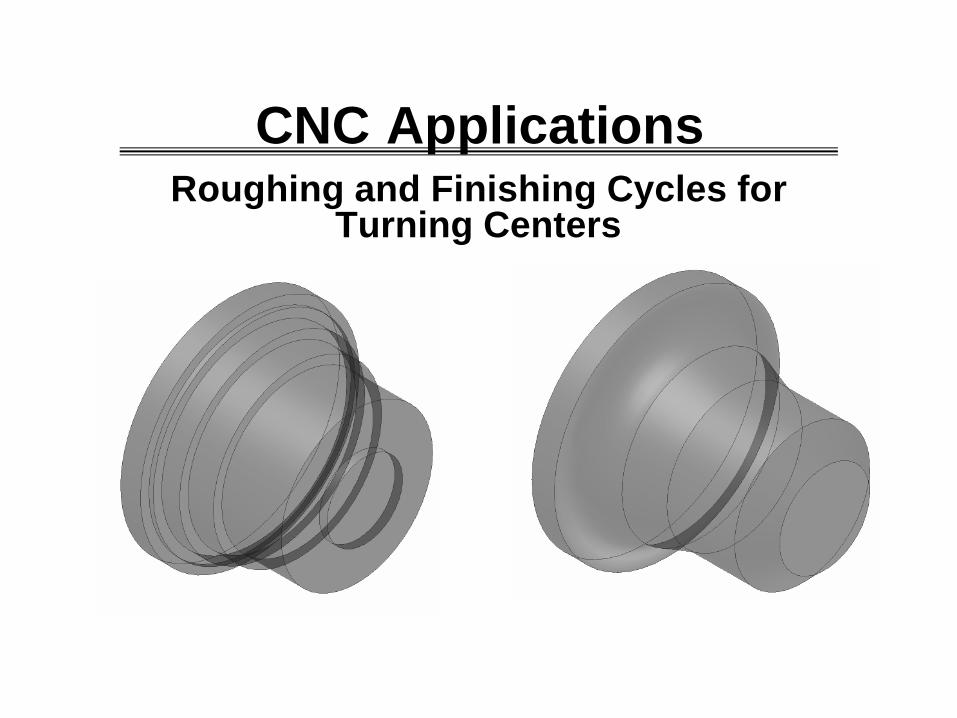
Roughing and Finishing Cycles for Turning Centers
CNC Applications

The Problem
In turning, we frequently encounter parts similar to the examples we have been using with multiple diameters, tapers, chamfers, and radii. These features pose problems for roughing.
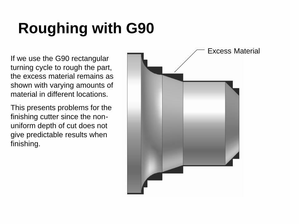
Roughing with G90Excess Material
If we use the G90 rectangular turning cycle to rough the part, the excess material remains as shown with varying amounts of material in different locations.
This presents problems for the finishing cutter since the non-uniform depth of cut does not give predictable results when finishing.

What We Really WantExcess Material
What we really want is a roughing cycle that leaves a uniform amount of material so the finishing cutter will perform its job properly.
Since this is such a common occurrence in turning, the control manufacturers use G71 to rough leaving a specified amount of excess material and G70 to finish.
These two cycles greatly simplify programming complex parts.

Program Format with G71 and G70
.
G71 P10 Q20 U0.06 W0.005 D1250 F0.012 S600N10 G0 …..N20 G0 G40 …
Tool Change – Load the Finishing Tool, Turn Comp On.G70 P10 Q20.
Load roughing tool and locate at initial point.
Program lines between N10 and N20 describe the FINISH pass only. The machine roughs for us.
The Finishing Cycle refers back to the same program lines that the roughing cycle used since those lines describe the finish pass.
Your program loads the roughing tool and locates it at the cycle start point. The feed and speed values in the G71 line are used for roughing. Any speed and feed values in the N10-N20 program lines are used for finishing. The machine roughs based on the finish pass data. Then, load the finish tool and the G70 uses the same N10-N20 lines to cut the finish pass.
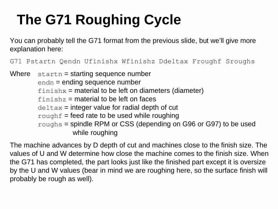
The G71 Roughing CycleYou can probably tell the G71 format from the previous slide, but we’ll give more explanation here:
G71 Pstartn Qendn Ufinishx Wfinishz Ddeltax Froughf Sroughs
Where startn = starting sequence numberendn = ending sequence numberfinishx = material to be left on diameters (diameter)finishz = material to be left on facesdeltax = integer value for radial depth of cutroughf = feed rate to be used while roughingroughs = spindle RPM or CSS (depending on G96 or G97) to be used
while roughing
The machine advances by D depth of cut and machines close to the finish size. The values of U and W determine how close the machine comes to the finish size. When the G71 has completed, the part looks just like the finished part except it is oversize by the U and W values (bear in mind we are roughing here, so the surface finish will probably be rough as well).
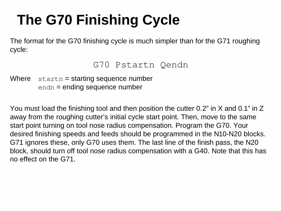
The G70 Finishing CycleThe format for the G70 finishing cycle is much simpler than for the G71 roughing cycle:
G70 Pstartn QendnWhere startn = starting sequence number
endn = ending sequence number
You must load the finishing tool and then position the cutter 0.2” in X and 0.1” in Z away from the roughing cutter’s initial cycle start point. Then, move to the same start point turning on tool nose radius compensation. Program the G70. Your desired finishing speeds and feeds should be programmed in the N10-N20 blocks. G71 ignores these, only G70 uses them. The last line of the finish pass, the N20 block, should turn off tool nose radius compensation with a G40. Note that this has no effect on the G71.

A G71/G70 Example
Ø2.500 Ø1.500
R0.375
0.2500.625
1.000
2.000
Ø1.750
0.25x45°
Note that this is the same example we did for tool nose radius compensation. However, in this program we will rough the part at 600fpm and 0.012ipr feed with a C insert tool T02. Then we will finish the profile at 800fpm and 0.006ipr with a V insert T03. Finally, we will part the tool off with an 1/8” wide parting tool T05 at 600 fpm and 0.004ipr. We will use G41 nose radius compensation for the finish cut with T03 only.

Follow Planning and Programming Steps (1-5)1. Examine drawing.2. How will we hold the raw material – in a 3 jaw chuck.3. Decide what cutters to use – given the following (use CSS for all cutters):
• Roughing – C insert at 600fpm and 0.012ipr, T02• Finishing – V insert at 800fpm and 0.006ipr, T03• Parting – 1/8” wide parting tool at 600fpm and 0.004ipr, T05
4. Write down the exact sequence of operations:A. Face the part to length using T02.B. Rough the profile leaving 0.060” excess on diameters and 0.005” on faces.C. Finish the profile with cutter compensation.D. Part to X0.050 with the G75 parting cycle.E. Program end.
5. Convert the sequence of operations to a program:Program Start
FaceRough TurnFinish Turn
PartProgram End

Facing
Program Start
Load the C insert tool.
Cap the RPM.Set the cutting speed to 600fpm, forward direction.Rapid to the starting point for facing in Zand in X.Rough Face
Position for finish facing
Increase cutting speed for finishing, G96 is still active.Finish facing.Move to initial position for the roughing cycle in Zand in X..Remainder of the program follows..
% O999G20 G40 G99 G28 U0 G28 W0T0202 G54G50 S4000G96 S600 M3 G0 Z2.005X2.875G1 X0 F0.012G0 Z2.1X2.875Z2.00S800G1 X0 F0.006G0 Z2.1X2.875...
ActionProgram Codes

Roughing & Finishing
Roughing cycle parameters.Move to the start of the chamfer, 0.1 clear in Z.Set finishing cutting speed (G71 uses 600).Machine the chamfer.Machine the straight 1.0” diameter.Machine the taper.Machine the radius.Feed clear in Z leaving room for the parting tool.Feed clear in X.Move to turn off nose radius compensation.
Tool change.
Load the V insert tool.
Move to tool nose compensation point in Zand in X.Turn on tool nose radius compensation.Perform the finishing cycle.
Remainder of the program follows.
G71 P10 Q20 U0.060 W0.005 D1250 S600 F0.012 N10 G0 X0.8
S800G1 X1.5 Z1.75 F0.006Z1.0X1.75 Z0.625G2 X2.5 Z0.25 I0.375 Z-0.15X2.875
N20 G40 X3.075 Z-0.25M9 M5 G28 U0 G28 W0 T0303 G54G50 S4000G96 S800 M3 G0 Z2.2X3.075G41 X2.875 Z2.1G70 P10 Q20...
ActionProgram Codes

How the G71 Works
Cycle Start Point
1. Rapid to depth, each cut D deep.
2. Feeds over to the profile,follows profile to previous cut.
3. Rapids to initial Z.

How the G70 Works
G41 Start Point
Cycle start pointwith G41 on.
G40 called inblock N20.
Initial rapid movein cycle, block N10.
Cutter returns to cycle start point.
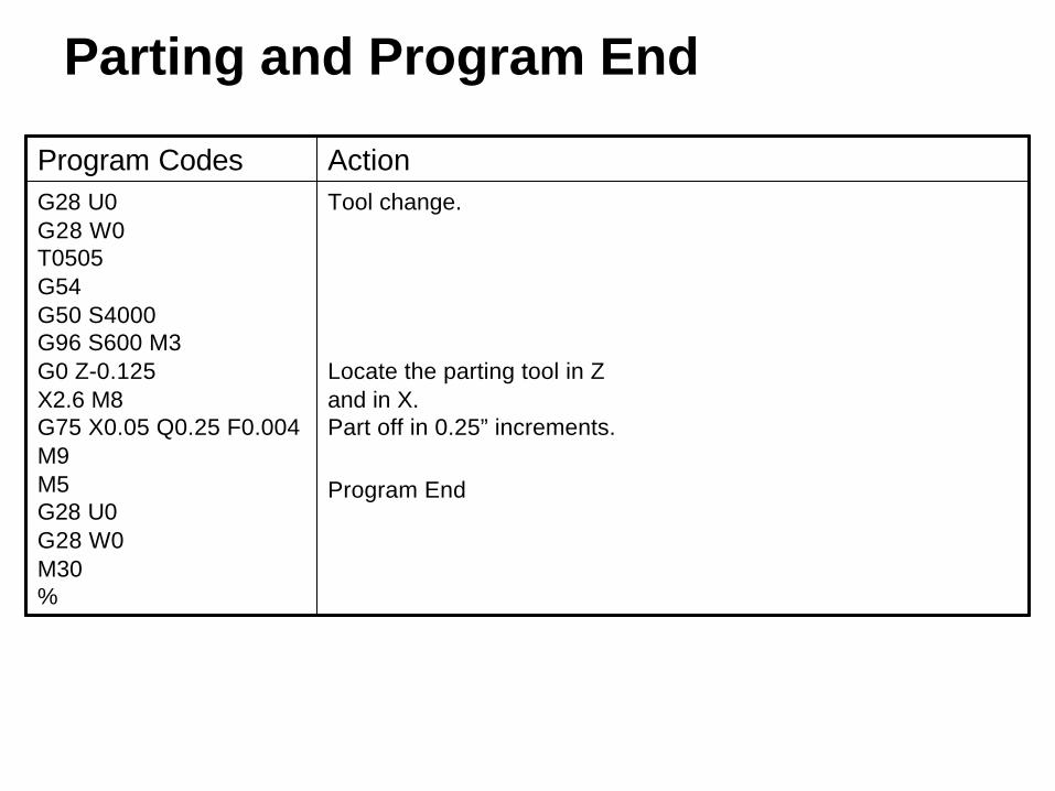
Parting and Program End
Tool change.
Locate the parting tool in Zand in X.Part off in 0.25” increments.
Program End
G28 U0 G28 W0T0505 G54G50 S4000 G96 S600 M3 G0 Z-0.125X2.6 M8G75 X0.05 Q0.25 F0.004M9 M5 G28 U0 G28 W0 M30 %
ActionProgram Codes
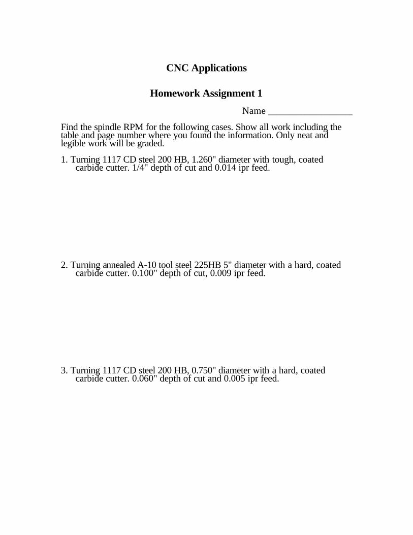
CNC Applications
Homework Assignment 1
Name _________________
Find the spindle RPM for the following cases. Show all work including thetable and page number where you found the information. Only neat andlegible work will be graded.
1. Turning 1117 CD steel 200 HB, 1.260" diameter with tough, coatedcarbide cutter. 1/4" depth of cut and 0.014 ipr feed.
2. Turning annealed A-10 tool steel 225HB 5" diameter with a hard, coatedcarbide cutter. 0.100" depth of cut, 0.009 ipr feed.
3. Turning 1117 CD steel 200 HB, 0.750" diameter with a hard, coatedcarbide cutter. 0.060" depth of cut and 0.005 ipr feed.

Homework Assignment 2
Name _________________
Find the spindle RPM and feed rate in IPM for the following cases. Show allwork including the table and page number where you found the information.Only neat and legible work will be graded.
1. Milling CD wrought aluminum with a 3/4” diameter 2 flute HSS end millwith 0.25 depth of cut.
2. Milling C36000 CD free cutting brass 100 HB with a 3" diameter 24 toothHSS slotting cutter. Use the fastest feed possible.
3. Milling 8620 steel 200 HB with a 1" diameter HSS endmill with 4 teeth at1/8” depth of cut.
4. Milling annealed A-2 tool steel 225 HB with a 6" diameter HSS facemillwith 8 teeth. Use the slowest feed possible.

CNC Applications
Turning Center Assignment 1
Name _________________ Write a program for the CNC turning center to make the following part:
The part is made from 1117 steel at 200 HB with a rough bar size of 1.260". Make two facing cuts at 1/16" depth each and turn the part with T0202, and then part of the part with T0505. When parting off, stop at X0.050 so the part does not fly off. Turn in the following items: 1. A printout of the program with an explanation of each program line. 2. A drawing with plotted points for each move made in the program.
Reference these points to the program. 3. All speed and feed calculations.

CNC Applications
Turning Center Assignment 2
Name _________________ Write a program for the turning center to make the following part:
The part is made from 1117 steel at 200 HB with a rough bar size of 1.260". With T0202, make two facing cuts at 1/16" depth each leaving 0.005 to finish, and then rough turn the part leaving 0.080 for finish on diameters and 0.005 on faces. Use G90 for roughing. Finish with T0303 and thread with T0404. When parting off with T0505, stop at X0.050 so the part does not fly off. Justify your speeds and feeds for each cut. Turn in the following items: 1. A printout of the program with an explanation of each program line. 2. Speed and feed calculations.

CNC Applications
Turning Center Assignment 3
Name _________________ Write a program for the turning center to make the following part:
The part is made from 1117 steel at 200 HB with a rough bar size of 1.260". With T0202, make two facing cuts at 1/16" depth each leaving 0.005 to finish, and then rough turn the part leaving 0.080 for finish on diameters and 0.005 on faces. Use G90 for roughing. Finish with T0303 using tool nose radius compensation, and thread with T0404. Cut the 1"R with tool 1 before threading. When parting off with T0505, stop at X0.050 so the part does not fly off. Justify your speeds and feeds for each cut. Turn in the following items: 1. A printout of the program with an explanation of each program line. 2. Speed and feed calculations.

CNC Applications
Turning Center Assignment 4
Name _________________ Write a program for the turning center to make the following part:
The part is made from 1045 steel at 200 HB with a rough bar size of 1.262". With T0505, make two facing cuts at 1/16" depth each leaving 0.005 to finish, and then rough turn the part leaving 0.080 for finish on diameters and 0.005 on faces using G71. Be sure to use nose radius compensation. Use G70 for finishing with T0303. Thread with T0404. Use G75 for parting with T0505, and stop at X0.050 so the part does not fly off. Turn in a printout of the program with an explanation of each program line.
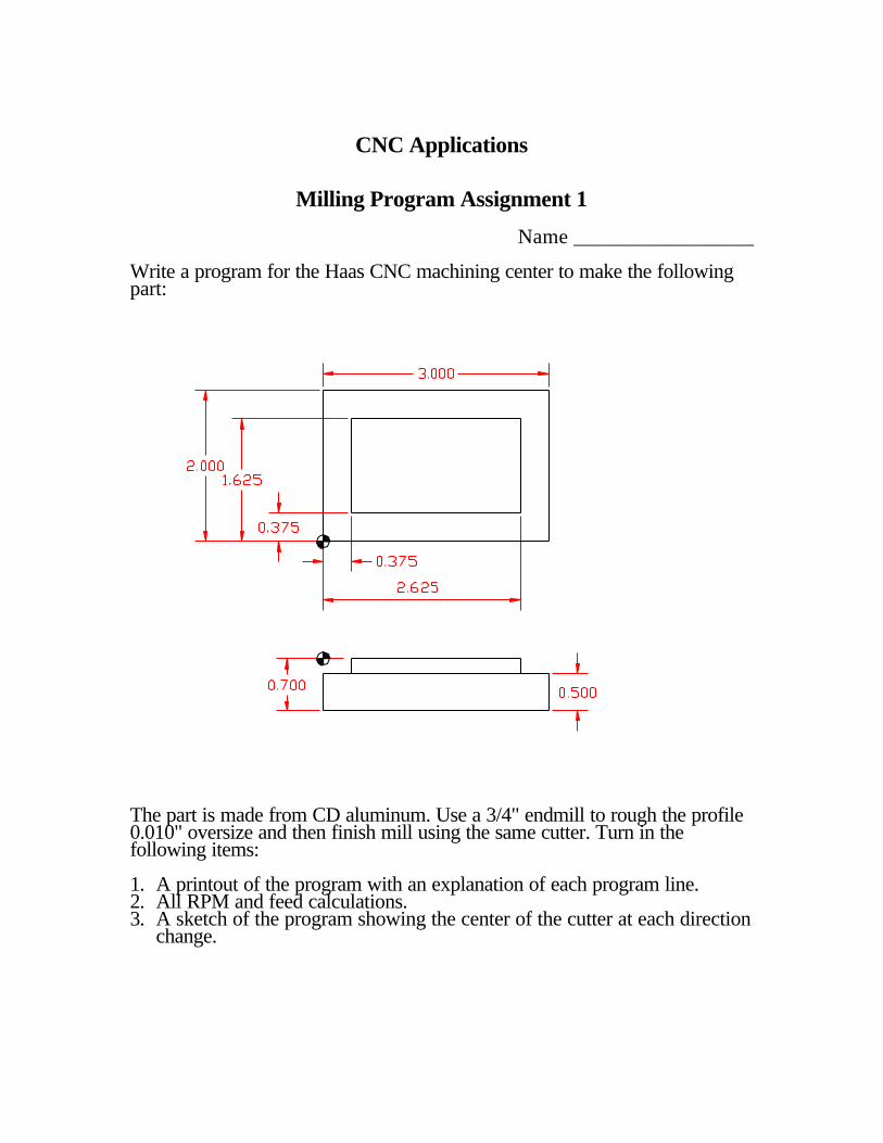
CNC Applications
Milling Program Assignment 1
Name _________________
Write a program for the Haas CNC machining center to make the followingpart:
The part is made from CD aluminum. Use a 3/4" endmill to rough the profile0.010" oversize and then finish mill using the same cutter. Turn in thefollowing items:
1. A printout of the program with an explanation of each program line.2. All RPM and feed calculations.3. A sketch of the program showing the center of the cutter at each direction
change.

CNC Applications
Milling Program Assignment 2
Name _________________
Write a program for the Haas CNC machining center to make the followingpart:
The part is made from CD aluminum. Use a 3/4" endmill to rough all features0.010" oversize and then finish mill using the same cutter. Turn in thefollowing items:
1. A printout of the program with an explanation of each program line.2. All RPM and feed calculations.3. A sketch of the program showing the center of the program at each
direction change.

CNC Applications
Machining Center Program Assignments 3 & 4
Name _________________
Write two programs for the Haas machining center to make the following part. Program 3 machines all features except the holes with a ¾” endmill (T1) and a ¼” endmill (T17). Program 4 centerdrills (T20), drills (T19), and taps (T18) only.
Turn in the following items: 1. All speed and feed calculations. 2. A printout of the programs.

CNC Applications
Machining Center Program Assignments 5 & 6
Name _________________ Write two programs for the Haas machining center to make the following
parts. Program 5 machines the length and thickness of the female part with a ¾” endmill (T1) and mills the pocket with a ½” endmill (T2). Program 6 mills the length, thickness, and boss of the male part with a ¾” endmill (T1). Use G41 cutter diameter compensation for the pocket and boss. The two parts should fit together snugly when finished.
Turn in the following items: 1. All speed and feed calculations. 2. A printout of the programs.