computer numeric control (cnc) machine operation · computer numeric control (cnc) machine...
TRANSCRIPT
Computer Numeric Control(CNC) Machine Operation
Juan P. CorreaENT 4499 - Culmination

IntroductionWelcome to the world of learning CNC operation. CNC stands for Computer Numeric Control. CNC machines are automated, computer programmed cutting machines. CNC machines can cut through metal, wood, plastics, foam and other materials. Because of their precision and speed they are widely used in the entertainment industry.
My goal this semester was to see how much I could learn about CNC including familiarizing myself with various Computer Aided Machining (CAM) softwares. I drafted projects, conducted interviews, read books and spent a week at Showman Fabricators shadowing operators.

CNC History● 1949-1953 US Government contracts The Parsons Corp and
MIT to develop the first NC system
● 1953 The Cincinnati Tool Co. converts a milling machine into a 3-Axis (X,Y,Z) automatic mill driven by a servo motor.
● 1956 Alfred Herbert Ltd develops the first NC tool path operated control system in the UK
● 1960-1970 Revolutionary advances make CNC reality. Geometries are controlled and changed by programs. Development and lead time is reduced. Manufacturing small batches and “one-offs” becomes profitable.
● 2015-Future CNC machines have become an essential part of manufacturing industries and are more available and affordable than ever. DIY kits allow individuals to have one in their home.

Basic CNC Machine AnatomyCNC machines come in different sizes and configurations. However most machines share the same basic parts and mechanics.
1. Bed
2. Gantry ( X and Y axis)
3. Gantry Track and Guide Rail
4. Tool
5. Spindle & Spindle Motor
6. Servo Motor
1 4
6
2
3
5
The Precix 1110 3-Axis Milled used at NYCCT. Specs: 5’X10’ bed, 18000rpm spindle, Single tool.
7
7. E-Stop
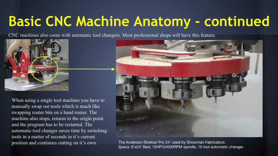
Basic CNC Machine Anatomy - continuedCNC machines also come with automatic tool changers. Most professional shops will have this feature.
The Anderson Stratos/ Pro 24’ used by Showman Fabricators. Specs: 6’x24’ Bed, 15HP/24000RPM spindle, 10 tool automatic changer.
7
When using a single tool machine you have to manually swap out tools which is much like swapping router bits on a hand router. The machine also stops, returns to the origin point and the program has to be restarted. The automatic tool changer saves time by switching tools in a matter of seconds in it’s current position and continues cutting on it’s own.

ConceptBasic CNC machines work based on the Cartesian coordinate system (3 - axis (X,Y,Z) planes). The material is is usually laid on the bed of the machine and secured by suction. Below is a brief explanation of how a CNC Machine moves to cut a shape.
A) The spindle spins the tool as it plunges down into the material on the Z axis
C) In this case the machine moves in the X,Y axis while drilling holes in the Z axis
X, Y Travel, Z Axis Cutting (Top View)
X, Y Axis(Top View)
Z-Axis(Profile View)
X
Y Path and Movement of Spindle
B) To cut this shape, the tool path may begin its travel on either the X or Y axis depending on the “G” Code.
Mechanics
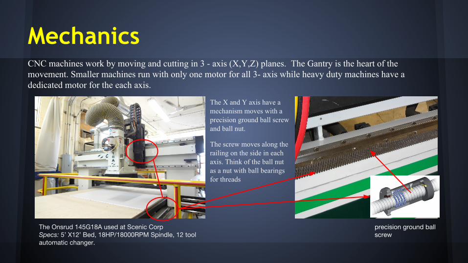
The Onsrud 145G18A used at Scenic CorpSpecs: 5’ X12’ Bed, 18HP/18000RPM Spindle, 12 tool automatic changer.
CNC machines work by moving and cutting in 3 - axis (X,Y,Z) planes. The Gantry is the heart of the movement. Smaller machines run with only one motor for all 3- axis while heavy duty machines have a dedicated motor for the each axis.
precision ground ball screw
The X and Y axis have a mechanism moves with a precision ground ball screw and ball nut.
The screw moves along the railing on the side in each axis. Think of the ball nut as a nut with ball bearings for threads

The “G” CodeThe “G” code is what makes CNC machines run. The code gives the machine the instructions on what tools it needs, speeds and the tool path to run. CAM software generates the G code which is then transferred into the machine control center.
Common G - Code commands
G90 - Absolute Mode
G80 - Cancel Canned Cycles
G40 - Cancel Cutter Compensation
G0 - Move in Rapid Mode
N100 is the number of the line of code. It’s always a good idea to see how many lines of code you have generated as some machines have a limited number of lines they can process at one time and will require that you break up the code into “different jobs”.

The “G” Code - Continued
Brief Example of a functioning Code%T2 M6S1400 M03G0 G54 X0 Y0G43 H1 Z1.X - 1.625 Y -.625%
Explaining The Code% in some machines it is used to mark the start and end of the program
T2 is # of the tool to be installed M6 installs the tool
S1400 is the spindle speed (1,400RPM) M03 turns on the spindle
G0 sets the machine to move in rapid mode (100% of a defined speed in inches per minute, i.e 400 in/min)
G54 sets the absolute starting point. X0 Y0 in this case it is 0 on the X-Axis and 0 on the X-Axis. (this may be defined anywhere on the material being cut)
G43 picks up a tool to the offset length H1 defines offset length (.001mm) Z1. Raises the tool in the Z-Axis by 1 inch in rapid mode
The “G” Code - Continued
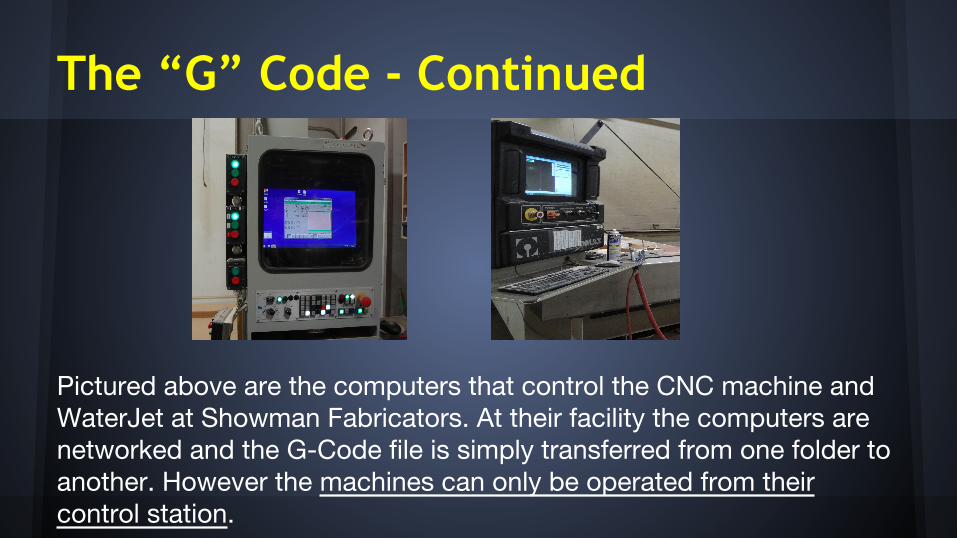
Pictured above are the computers that control the CNC machine and WaterJet at Showman Fabricators. At their facility the computers are networked and the G-Code file is simply transferred from one folder to another. However the machines can only be operated from their control station.

Data Chain
CAD
● “Save As” or “Export” the File as a DXF
CAMDXF
● Once exported, the file can be opened by the CAM software. It is CAM that you can set up the dimension of your material, tool order and generate G code.
G-CodeCNC ComputerCNC Machine Software
● The G-Code is transferred into a folder which the CNC’s computer can access. The code is sometimes generated as a .txt file.
● The G-Code is loaded into the CNC machine’s proprietary software and runs the program

Computer Aided Machine (CAM) SoftwareOne of the challenges in training as a CNC operator is learning various types of CAM software. At Showman Fabricators they use Sigmanest, Enroute, OMAX Layout (WaterJet). While at Scenic Corp and NYCCT Architecture uses RhinoCAM. However, NYCCT Engineering uses MasterCAM. In addition you must also familiarize yourself with the software used to actually operate the machine

ToolingCNC machines can be thought of as big fancy computerized routers. In order to get the product you want you must choose the right tool. Like materials, tools also come in different shapes and sizes. In addition some are more robust than others.

Tooling - continuedTools come in different types for different jobs. In the entertainment industry realized that some bits are de facto standards for almost every job. The type of material, thickness and hardness are things to consider when choosing the tool(s) for the Job. The tool that you use will help decide on your settings for spindle speed, plunge rate, and feed rate
Most Commonly used bits: Upcut Spiral O Flute Chipbreaker bitsCompression Bit (Carbide Coated)Engraving Bits
Settings to Consider for tool and Material being cut
- Spindle Speed (SS) - Plunge Rate (PR) - Feed Rate (FR)
SS measured in RPM - Rotations Per minute
PR and FR measured in IPM - Inches Per Minute

Tooling - continuedTool Properties and Descriptions
Single Flute - Upcut Spiral O FluteThis tool is mainly used to cut plexiglass. The upcut feature pushes the chips up so that they don’t weld back into the piece being cut.
Single Flute Bottom view
Material: 1 ½” Plexiglass
Machine: Stratos/Pro 24’
Tool Width : ½”
Settings:SS: 18,000 RPMPR: 450 IPMFR: 500 IPM

Tooling - continuedTool Properties and Descriptions
Chip-Breaker/Hogger This tool is mainly used to cut deep into hard or very thick materials. The spike like extrusions give a rough edge to the cut but it does the job quickly. A finer tool is usually used to go over the area to smooth out the cut
3 Flute Bottom view
Material: 1 ½” MDF
Machine: Stratos/Pro 24’
Tool Width : ¾”
Settings:SS: 18,000 RPMPR: 500 IPMFR: 600 IPM

Tooling - continuedTool Properties and Descriptions
Compression Bit This tool is the most widely used bit in entertainment fabrication shops (about 60% for Scenic Corp). The tool has spirals in 2 different directions. This gives clean finish on both sides when cutting through veneer and composite materials. The spirals also help move chips out of the tool path
Material: ½” MDO
Tool Width : ⅜ “
Machine: Stratos/Pro 24’
Settings:
SS: 18,000 RPMPR: 300 IPMFR: 200 IPM
3 Flute Bottom view

Tooling - continuedTool Properties and DescriptionsEngraving BitsThese tools are used to do exactly what the name says. I found that when engraving is not critical most operators will use whatever tool is first to cut and set the depth of the cut to about 1/8”- 3/16”.
Material: ½” Plexi
Tool: ¼” V-Cut Aluminum bit Machine: Roland MDX-540
Settings:SS: 800 RPMPR: 40 IPMFR: 50 IPM
¼” V-Groove AluminumCarbide Tip Engraving Bit

What can we make with CNC Machines?- A Detailed Brick Wall
- Signs
- Cool Furniture

Things I did make