cms pixels upgrade co2 cooling transfer lines · • construction & commissioning of plant and...
TRANSCRIPT

CMS Pixels upgrade CO2 cooling transfer lines
Draft spec – for introduction
Paola Tropea & Hans Postema
5 December 2012
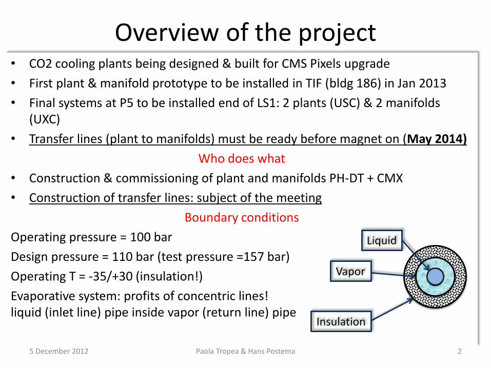
• CO2 cooling plants being designed & built for CMS Pixels upgrade
• First plant & manifold prototype to be installed in TIF (bldg 186) in Jan 2013
• Final systems at P5 to be installed end of LS1: 2 plants (USC) & 2 manifolds (UXC)
• Transfer lines (plant to manifolds) must be ready before magnet on (May 2014)
Who does what
• Construction & commissioning of plant and manifolds PH-DT + CMX
• Construction of transfer lines: subject of the meeting
Boundary conditions
Operating pressure = 100 bar
Design pressure = 110 bar (test pressure =157 bar)
Operating T = -35/+30 (insulation!)
Evaporative system: profits of concentric lines! liquid (inlet line) pipe inside vapor (return line) pipe
Overview of the project
Liquid
Vapor
Insulation
5 December 2012 Paola Tropea & Hans Postema 2
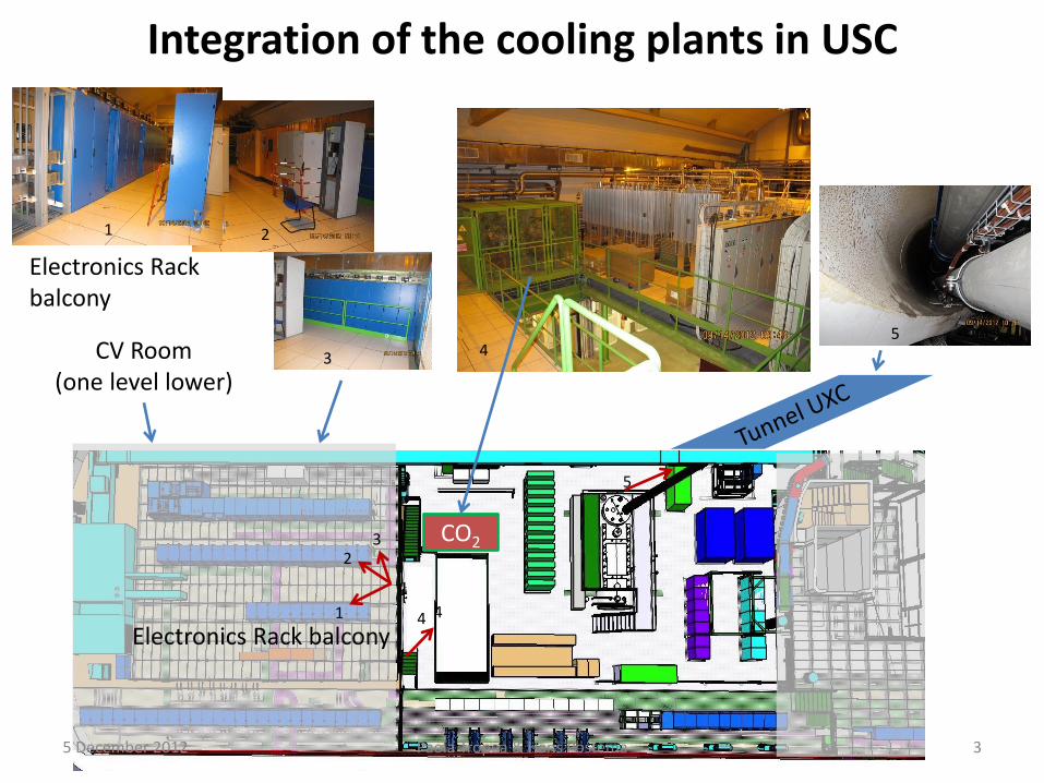
Integration of the cooling plants in USC
Electronics Rack balcony
1 2
3 4 CV Room (one level lower)
5
CO2
4 1
2 3
5
Electronics Rack balcony 4
5 December 2012 Paola Tropea & Hans Postema 3

CO2 cooling system in USC: foot print 4
13
5
3000
1680
10
00
Cooling Plant
Accumulator 600x900
1680
Cooling Plant
access from both sides
10
00
Accumulator 600x900
Electronics Racks (x2)
Two concentric transfer lines (insulated, vacuum?), one per cooling plant from USC to UXC
5 December 2012 Paola Tropea & Hans Postema 4

3
1 2
USC55 UXC55
Transfer lines from USC to UXC Preliminary sketch – integration studies on-going
-Z E
nd
+
Z E
nd
TX
54 Manifolds
Manifolds
CO2 plants
5 December 2012 Paola Tropea & Hans Postema 5

Plumbing
Manifolds in UXC
Freon Chiller (CV room)
Tunnel to UXC
Pneumatic Air &
5 December 2012 Paola Tropea & Hans Postema 6

CO2 Plumbing: Plant to Manifolds
Plug! (Insulation)
Rail system 2 insulated, concentric tubes through the ~20m tunnel
Jerome
5 December 2012 Paola Tropea & Hans Postema 7

Experiment Cavern
Transfer lines exit area in UXC from USC
5 December 2012 Paola Tropea & Hans Postema 8

Transfer lines in UXC: from the UXC entrance to the manifolds Option 1) over CMS: abandoned Option 2) along the wall: ok
5 December 2012 Paola Tropea & Hans Postema 9

In the USC (1)
5 December 2012 Paola Tropea & Hans Postema 10
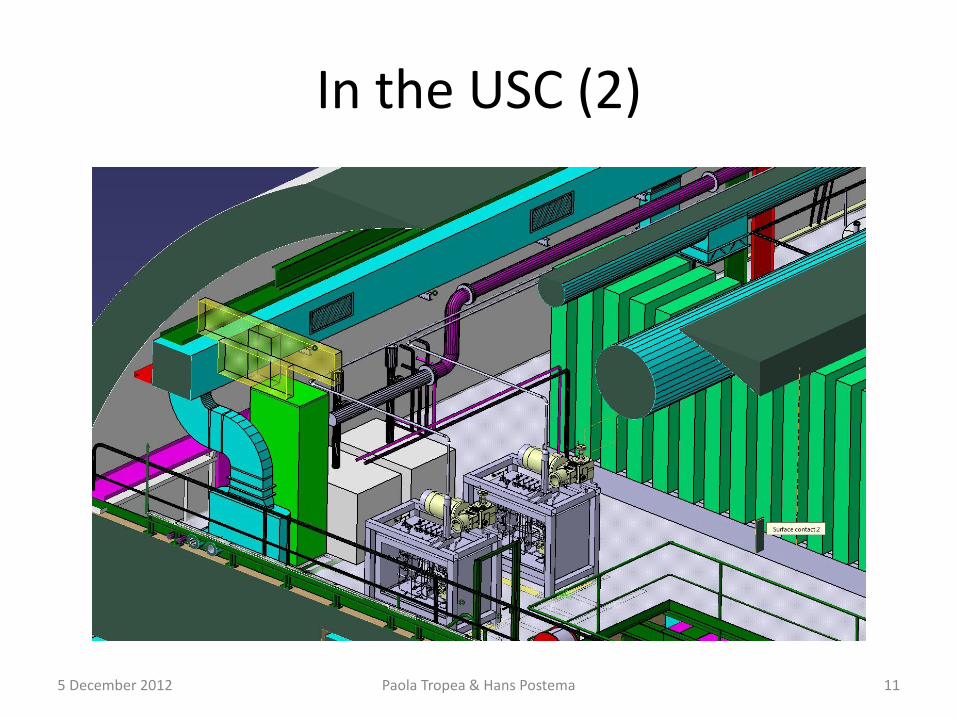
In the USC (2)
5 December 2012 Paola Tropea & Hans Postema 11

In the USC (3)
5 December 2012 Paola Tropea & Hans Postema 12

In the UXC (1)
5 December 2012 Paola Tropea & Hans Postema 13
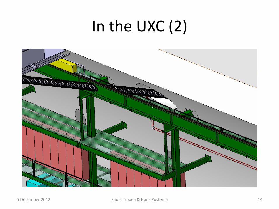
In the UXC (2)
5 December 2012 Paola Tropea & Hans Postema 14

In the UXC (3)
5 December 2012 Paola Tropea & Hans Postema 15

To Pixel Detector: Branch to existing copper tubes
5 December 2012 Paola Tropea & Hans Postema 16

Possible products?
Sept 2010
Vacuum Insulated Lines for CO2 (VICO2-Lines)
General
VICO2-Lines are specially designed to transfer liquid or gaseous CO2 with low pressure
drops and a very low heat in leak.
Characteristics
VICO2-Lines have a very low heat in-leak because of the high static
vacuum level. By their design pressure of 40 bar(g) and design temperature
of -78C , these lines are very well suited for many application in several industries.
Description
DeMaCo’s VICO2-Lines basically consists of an inner stainless steel
pipe, which transfers the (liquef ed) CO2, and an outer stainless steel
pipe which forms the vacuum jacket.
The VIP is manufactured in pre-fabricated spools. Normally DeMaCo
supplies spools with a process line of pipe Ø28x1 with a length up
to 5m. Other diameters and / or longer lengths can be supplied at
all times.
The spools are evacuated in our workshop. To ensure a longer pe-
riod of high quality vacuum each spool is helium leak tested and a
vacuum retention test of 24 hours is executed on all spools.
DeMaCo Holland bv
Oester 2
Postbus 4
NL 1723 ZG Noord-Scharwoude
www.DeMaCo.nl
Tel.: +31(0)226 33 21 00
Fax: +31(0)226 33 21 11
ISO 9001 - ISO 3834-2 - PED H/H1 - VCA**
For the connection of the lines, two types of couplings are available. The process lines can be connected by welding or by an union coupling. Both
couplings are conventional insulated and covered with a removable stainless steel sleeve.
Alternative Design conditions, materials, Dimensions, QA or other special requirements can be designed by DeMaCo and shall be quoted on request.
Advantages of DeMaCo VICO2-lines
● Low Price / Short delivery time because of the simple design
● Smaller outer diameter compared to conventional insulated pipe lines
● Up to 30 times lower heat in-leak than conventional insulated pipe lines
● Easy to install
● No external insulation required
● After delivery up to f ve years maintenance free
● Easy extension, re-routing, dismantling and re-using of the line without
af ecting the vacuum of the spools
Additional features
● Appendages (valves, safety valves, gas vents, etc.)
● Cryogenic engineering and design
● On-site measurements
● Erection
● Annual inspection
● Maintenance of the spools (evacuation)
● On-site services
5 December 2012 Paola Tropea & Hans Postema 17

Schedule
• Sept 2012/Mar 2013 – Design
• Dec 2012 / Mar 2013 – Specifications
• Feb 2013/April 2013 - Verification of the design on site
• May 2013 - CMS Technical Coordination review on transfer line project
• June 2013 – Tender
• Sep 2013 – Place the order
• 2014 - Installation on site
• May 2014 - Mandatory availability of the transfer lines
5 December 2012 Paola Tropea & Hans Postema 18

Estimated dimensions (1)
• Inner tube needs about 10 mm diameter
• 110 bar design pressure
• Elastic limit above 1.5x110=165 bar (PED)
• Test at 1.43x110=157 bar (PED)
• 316L tube 12x1 mm, allowable working pressure: 200 bar, source: Swagelok
• Pressure reduction due to bending: TBD
• Increase in wall thickness is acceptable, if required
5 December 2012 Paola Tropea & Hans Postema 19

Estimated dimensions (2)
• Outside tube: DN25
• Pressures identical to inner tube
• EN ISO 1127, 33.7 mm OD, 3.2 mm wall, design pressure 244 bar, source Outo Kumpu
• Elbows with straight ends, ISO R=2D 33.7x3.2 mm, design pressure: 155 bar, source Outo Kumpu
• Welding methods: – By hand
– Orbital welding
– Orbital welding with filler material
5 December 2012 Paola Tropea & Hans Postema 20

Vacuum jacket
• Requesting DEMACO advice on spacing between outer tube and vacuum jacket
• Inner and outer tube have, by design, virtually the same temperature. No thermal expansion issue expected
• Thermal expansion issue between tube (-30 C) and jacket (+25 C)
• Requesting DEMACO advice on solution
5 December 2012 Paola Tropea & Hans Postema 21

Overall goals
• Writing specification for tender • Including DEMACO advice • Respecting your production capabilities • Optimization of cost by including DEMACO
experience • Optimize between on-site and off-site work • Avoiding differences in safety approach between
PED, DEMACO and CERN safety • Receive preliminary approval from safety before
placing the order
5 December 2012 Paola Tropea & Hans Postema 22
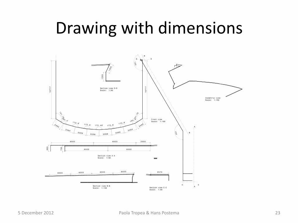
Drawing with dimensions
5 December 2012 Paola Tropea & Hans Postema 23