city construction standards & specifications
TRANSCRIPT

CITY CONSTRUCTION
STANDARDS & SPECIFICATIONS
DEBBIE MANNS, CITY MANAGER
ROBERT RIVERA, DIRECTOR OF PUBLIC WORKS
April 20, 2019
Public works construction management department

TABLE OF CONTENTS
DIVISION A GENERAL CONDITIONS
Section Page
A.1 INTRODUCTION A-1
A.2 COMMENCEMENT OF WORK A-1
A.3 USE OF City RIGHT-OF-WAY A-1
A.4 OTHER STANDARDS A-1
A.5 SAMPLING AND TESTING A-2
A.6 LEGAL RESTRICTIONS AND PERMITS A-2
A.7 PUBLIC CONVENIENCE AND SAFETY A-2
A.8 CHEMICAL USAGE A-3
A.9 PROTECTION OF PROPERTY A-3
A.10 RESTORATION OF PROPERTY A-3
A.11 WORK IN STREETS A-4
A.12 DISTRUPTION TO EXISTING SYSTEM OPERATION A-5
A.13 EROSION AND SEDIMENT CONTROL A-5
A.14 SURVEY AND CONSTRUCTION STAKES A-5
A.15 SURVEY BENCH MARKS AND MONUMENTS A-5
A.16 NAMEPLATES A-5
A.17
CHARACTER OF WORKMEN, SUPERINTENDENTS, AND EQUIPMENT A-6
A.18 SANITARY PROVISIONS A-6
A.19
CONFORMITY WITH PLANS AND ALLOWABLE DEVIATIONS A-6
A.20 SUBSTITUTIONS OR "APPROVED EQUALS" A-6
A.21 INSPECTION BY OTHER AGENCIES A-6
A.22 DEFECTIVE AND UNAUTHORIZED WORK A-6
A.23 WARRANTY A-7
A.24 UTILITY EASEMENTS A-7
A.25 INSTALLING NEW UTILITIES A-8
A.26 CERTIFICATION AND SUBMITTAL'S PARAGRAPH A-8
A.27 RECORD DRAWING A-8
A.28 PLANS SUBMITTALS A-8
DIVISION B
TECHNICAL REQUIREMENTS
Section B.1
UTILITY EXCAVATION, TRENCHING, AND BACKFILLING
B.1.1 GENERAL B-1
B.1.2 MATERIALS B-1
B.1.2.1 SHEETING AND BRACING B-1
B.1.2.2 CONCRETE B-1
B.1.3 TRENCHING B-1
B.1.3.1 TRENCH DEMINSIONS B-1
B.1.3.2 TRENCH GRADE B-1
B.1.3.3 UTILITY BEDDING B-1
B.1.3.4 UNSUITABLE MATERIAL BELOW TRENCH GRADE B-2
B.1.3.5 EXTRA UTILITY BEDDING MATERIAL B-2
B.1.3.6 SHEETING AND BRACING B-2
Section Page
B.1.3.7 EXCAVATED MATERIAL B-2
B.1.3.8 MATERIAL DISPOSAL B-2
B.1.3.9 BORROW B-2
B.1.3.10 ROCK EXCAVATION B-2
B.1.3.11 DEWATERING B-2
B.1.3.12 OBSTRUCTIONS B-3
B.1.3.13 BACKFILL IN EXISTING TRAFFIC ZONES - GENERAL B-3
B.1.3.13.1
BASE MATERIAL IN AREAS WITH HIGH GROUND WATER B-3
LEVEL OR OTHERWISE PRONE TO MOISTURE
B.1.3.13.2 PIPE ZONE B-3
B.1.3.13.3 SECOND AREA B-3
B.1.3.13.4 SHOULDER RESTORATION B-4
B.1.3.13.5 COMPACTION METHODS B-4
B.1.3.13.6 DENSITY TESTS B-4
B.1.3.14 BACKFILL IN NEW TRAFFIC ZONES B-4
B.1.3.15 BACKFILL IN NONTRAFFIC ZONES B-4
B.1.3.16 PROTECTIVE CONCRETE SLAB B-4
B.1.3.17 SEED AND MULCH B-4
B.1.3.18 TREE PROTECTIONS B-4
Section B.2
CASING PIPE - BORING AND JACKING
B.2.1 GENERAL B-5
B.2.2 CASING PIPE MATERIALS AND INSTALLATION B-5
B.2.3 CARRIER PIPES B-6
B.2.4 DIRECTIONAL BORING B-6
B.2.5 DIRECTIONAL DRILLING B-6
PART 1 - GENERAL
B.2.5.1.1 SCOPE B-6
B.2.5.1.2 ALTERNATIVES B-6
B.2.5.1.3 SYSTEM DESCRIPTION / DESIGN REQUIREMENTS B-6
B.2.5.1.4 SUBMITTALS B-6
B.2.5.1.5 QUALITY ASSURANCE B-7
B.2.5.1.5.1 QUALIFICATIONS B-7
B.2.5.1.5.2
REGULATORY REQUIREMENTS B-7
1.6 DELIVERY, STORAGE, HANDLING, & ENVIRONMENTAL REQUIREMENTS B-7
PART 2 - PRODUCTS
2.1 MATERIALS B-7
PART 3 - EXECUTION
3.1 PREPARATOIN B-7
3.2 INSTALLATION B-7
3.3 TESTING B-8
Section B.3
PIPE, FITTINGS, VALVES, AND APPURTENANCES
B.3.1 GENERAL B-8
B.3.2 PIPE AND FITTINGS B-9
B.3.2.1 GENERAL B-9
B.3.2.2 DUCTILE IRON, GENERAL B-9 B.3.2.2.1 PIPE B-9
B.3.2.2.2 FITTINGS B-9
Section Page
B.3.2.2.3 JOINTS B-9
B.3.2.2.4 COATINGS AND LININGS B-9
B.3.2.2.5 POLYETHYLENE WRAP B-10
B.3.2.3 POLYVINYL CHLORIDE (PVC) Water Mains, Reuse Mains, and Force Mains B-10
B.3.2.4 POLYVINYL CHLORIDE (PVC) Gravity Sewer Pipe B-10
B.3.2.5 POLYETHYLENE PLASTIC SERVICES Water and Reuse B-11
B.3.2.6 SPECIAL ITEMS B-11
B.3.2.6.1 EXPANSION JOINTS B-11
B.3.2.6.2 FLANGED COUPLING ADAPTERS B-11
B.3.2.6.3 CAST COUPLINGS B-11
B.3.2.6.4 SLEEVES AND WALL PIPES B-12
B.3.2.6.5 TAPPING SADDLES B-12
B.3.2.6.6 TAPPING SLEEVES B-12
B.3.2.6.7 SERVICE SADDLES B-12
B.3.3 VALVES B-12
B.3.3.1 GENERAL B-12
B.3.3.2 GATE VALVES B-12
B.3.3.2.1 UNDERGROUND SERVICE B-12
B.3.3.2.2 ABOVEGROUND SERVICE B-12
B.3.3.2.3 TAPPING VALVES B-12
B.3.3.2.4 VALVES LESS THAN TWO INCHES B-12
B.3.3.2.5 ACTUATORS B-13
B.3.3.3 CHECK VALVES (CV) B-13
B.3.3.3.1 GENERAL SERVICE B-13
B.3.3.3.2 CHECK VALVES TWO INCHES AND SMALLER B-13
B.3.3.4 PVC BALL VALVES B-13
B.3.3.5 CORPORATION STOPS AND CURB STOPS B-13
B.3.3.6 SLUICE GATES B-13
B.3.3.7 AIR RELEASE VALVES - AIR AND VACUUM VALVES B-13
B.3.3.7.1 SEWER SERVICE B-13
B.3.3.7.2 WATER SERVICE (VENT ONLY) B-13
B.3.3.8 SPECIAL ITEMS B-13

B.3.3.8.1 VALVE BOXES B-13
B.3.4 INSTALLATION B-13
B.3.4.1 GENERAL REQUIREMENTS B-13
B.3.4.2 DUCTILE IRON (DI) PIPE B-15
B.3.4.3 POLYVINYL CHLORIDE (PVC) PIPE) B-15
B.3.4.4 STEEL PIPE - GALVANIZED (GS) AND BLACK (BS) B-15
B.3.4.5 VALVES B-15
Section B.4
GENERAL PROVISIONS
B.4.1 GENERAL B-16
B.4.2 RELATED STANDARDS B-16
B.4.3 GENERAL REQUIREMENTS B-16
B.4.3.1 EQUIPMENT INSTALLATION B-16
B.4.3.2 MODIFICATIONS TO EXISTING EQUIPMENT B-16
B.4.3.3 SALVAGE B-16
B.4.3.4 EQUIPMENT OPERATING TESTS B-16
B.4.3.5 MANUFACTURER SUPERVISION B-16
B.4.3.6 OPERATING INSTRUCTIONS AND PARTS LISTS B-16
DIVISION C
SANITARY SEWER FACILITIES
Section C.1
SANITARY GRAVITY SEWERS
C.1.1 GENERAL C-1
C.1.2 DESIGN STANDARDS C-1
C.1.2.1 REQUIRED REFERENCE C-1
C.1.2.2 SYSTEM DESIGN C-1
C.1.2.2.1 AVERAGE DESIGN FLOWS C-1
C.1.2.2.2 PEAK DESIGN FLOWS C-1
C.1.2.2.3 SEWER SIZE COMPUTATION C-2
C.1.2.2.4 DESIGN CONSIDERATIONS C-2
C.1.3 STANDARD REQUIREMENTS C-2
C.1.3.1 GENERAL C-2
C.1.3.2 APPROVED PIPE C-3
C.1.3.3 SANITARY SEWER MANHOLES C-3
C.1.3.4 TERMINAL LAMPHOLES C-4
C.1.3.5 PIPE DEPTH AND PROTECTION C-4
C.1.3.6 PIPE BEDDING C-4
C.1.3.7 SPECIAL EXTERIOR PROTECTION FOR CORROSION C-4
C.1.3.8 CONNECTIONS AT STRUCTURES C-4
C.1.3.9 TRANSITION CONNECTIONS C-4
C.1.3.10 PIPE CUTTING C-4
C.1.3.11 SERVICE CONNECTIONS C-4
C.1.4 TESTING C-5
C.1.4.1 C-5
C.1.4.2 C-5
C.1.4.3 TELEVISON INSPECTION C-5
C.1.4.4 DEFLECTION TESTING C-5

C.1.4.5 SMOKE TESTING C-5
C.1.4.6 RECORD DRAWINGS "AS-BUILT" C-5
Section C.2
SANITARY SEWER FORCE MAINS
C.2.1 GENERAL C-6
C.2.2 DESIGN STANDARDS C-6
C.2.2.1 REQUIRED REFERENCE C-6
C.2.2.2 SYSTEM DESIGN C-6
C.2.2.3 OPERATIONAL COST CONSIDERATIONS C-6
C.2.3 STANDARD REQUIREMENTS C-6
C.2.3.1 GENERAL C-6
C.2.3.2 APPROVED PIPE, FITTINGS AND VALVES C-7
C.2.3.3 JOINT RESTRAINING C-7
C.2.3.4 PIPE DEPTH AND PROTECTION C-7
C.2.3.5 CONNECTIONS AT STRUCTURES C-7
C.2.3.6 SPECIAL EXTERIOR PROTECTION FOR CORROSION C-7
C.2.3.7 AIR AND VACUUM VENTING C-7
C.2.3.8 VALVE LOCATIONS C-8
C.2.3.9 CLEAN-OUT CONNECTIONS C-8
C.2.3.10 TERMINAL DISCHARGE C-8
C.2.3.10.1 DISCHARGE INTO MANHOLES C-8
C.2.3.10.2 DISCHARGE INTO PUMPING STATION WET WELLS C-8
Section Page
C.2.3.11 IDENTIFICATION C-8
C.2.4 TESTING C-8
C.3.1 GENERAL C-9
C.3.2 DESIGN STANDARDS C-9
C.3.2.1 REQUIRED REFERENCE C-10
C.3.2.2 DESIGN FLOWS C-10
C.3.2.3 PUMP SELECTION C-10
C.3.2.4 WET WELL DESIGN C-10
C.3.3 GENERAL REQUIREMENTS C-11
C.3.3.1 SITE C-11
C.3.3.2 STRUCTURES C-11
C.3.3.3 HOISTING EQUIPMENT C-11
C.3.3.4 PIPING SYSTEM FOR LIFT STATIONS C-11
C.3.3.5 STATION WATER SYSTEM C-12
C.3.3.6 PRESSURE GAUGES AND GAUGE CONNECTIONS C-12
C.3.3.7 EMERGENCY PUMP CONNECTIONS C-12
C.3.3.8 SEWAGE PUMPS AND MOTORS C-12
C.3.3.8.1 GENERAL C-12
C.3.3.8.2 PUMP CONSTRUCTION C-13
C.3.3.8.3 C-13
C.3.3.8.4 C-13
C.3.3.8.5 C-13
C.3.3.8.6 PUMP TEST C-13
C.3.3.8.7 PUMP WARRANTEE C-14
C.3.3.8.8 FACTORY SERVICES C-14

C.3.3.8.9 EXPERIENCE CLAUSE C-14
C.3.3.9 TELEMETERING SYSTEM C-14
C.3.3.10 EMERGENCY GENERATORS C-14
C.3.4 LIFT STATION CONSTRUCTION C-14
C.3.4.2 ACCESS FRAME AND GUIDES C-14
C.3.4.3 VALVE VAULT C-14
C.3.4.4 GRIP-EYE C-15
C.3.4.5 SWING CHECK VALVE C-15
C.3.5 RESPONSIBILITIES C-15
C.3.6 CONTROL PANEL C-15
C.3.6.1 GENERAL REQUIREMENTS C-15
C.3.6.2 C-16
C.3.6.3 C-16
C.3.6.4 C-16
C.3.6.5 ELAPSED TIME METERS C-16
C.3.6.6 CONVENIENCE RECEPTABLE C-16
C.3.7 ELECTRICAL CONTROLS C-16
C.3.7.1 INTENT OF SPECIFICATIONS C-16
C.3.7.2 WIRING C-16
C.3.7.3 ENCLOSURE C-16
C.3.8
LEVEL-RESPONSIVE AUTOMATIC PUMP AND ALARM CONTROL C-17
C.3.8.1 C-17
C.3.8.2 LIQUID LEVEL PUMP CONTROLLER C-17
C.3.8.3 MAIN POWER DISCONNECT C-17
C.3.8.4 ELECTRICAL JUNCTION BOX C-18
Section Page
C.3.8.5 LOCAL ALARM SYSTEM C-18
C.3.9 MANUFACTURER'S SHOP DRAWING C-18
C.3.10 WARRANTY C-19
C.3.11 EVALUATION OF MATERIALS C-19
C.3.12 INSPECTION C-20
C.3.13 START-UP / FINAL ACCEPTANCE C-20
DIVISION D
POTABLE WATER FACILITIES
Section D.1
WATER DISTRIBUTION SYSTEMS
D.1.1 GENERAL D-1
D.1.2 DESIGN STANDARDS D-1
D.1.2.1 REQUIRED REFERENCE D-1
D.1.2.2 SYSTEM DESIGN D-1
D.1.2.2.1 NORMAL FLOW DEMANDS D-1
D.1.2.2.2 SYSTEM SIZE COMPUTATION D-1
D.1.2.2.3 VALVE LOCATIONS D-1
D.1.2.2.4 PIPELINE HORIZONTALS SEPARATION D-1
D.1.3 STANDARD REQUIREMENTS D-2
D.1.3.1 GENERAL D-2

D.1.3.2 APPROVED PIPE, FITTINGS, AND VALVES D-2
D.1.3.3 FIRE HYDRANTS D-2
D.1.3.3.1 HYDRANT DESIGN D-2
D.1.3.3.2 HYDRANT SPACING D-3
D.1.3.3.3 HYDRANT ELEVATION D-3
D.1.3.3.4 HYDRANT CONNECTION TO FIRE MAIN D-3
D.1.3.3.5 HYDRANTS PROTECTION (BOLLARDS) D-3
D.1.3.4 RESTRAINED JOINTS D-3
D.1.3.5 PIPE DEPTH AND PROTECTION D-3
D.1.3.6 CONNECTIONS AT STRUCTURES D-3
D.1.3.7 SPECIAL EXTERIOR PROTECTION FOR CORROSION D-4
D.1.3.8 AIR VENTING AND BLOW-OFFS D-4
D.1.3.9 IDENTIFICATION AND TRACE GROUND WIRE D-4
D.1.3.10 SERVICE CONNECTIONS D-4
D.1.3.11 BULK WATER METER APPLICATIONS (THREE INCH AND LARGER) D-4
D.1.3.12 BACKFLOW PREVENTION D-5
D.1.3.12.1
BACKFLOW PREVENTION ENFORCEMENT, NEW SERVICES D-5
D.1.3.12.2 BACKFLOW PREVENTION DEVICES D-5
D.1.3.12.3 FIRE SERVICE D-5
D.1.3.12.4 IRRIGATION SYSTEMS D-5
D.1.4 TESTING D-5
D.1.5 DISINFECTING D-6
Section D.2
POLICY FOR CROSS CONNECTION CONTROL
D.2.1 GOVERNING AGENCIES D-7
D.2.1.1 AUTHORITY D-7
D.2.1.2 ENFORCEMENT D-7
D.2.1.3 CROSS-CONNECTION DETECTION AND PREVENTION D-7
D.2.2 DEFINITIONS D-7
Section Page
D.2.2.1 BACKFLOW D-7
D.2.2.2 BACKFLOW PREVENTION ASSEMBLY D-7
D.2.2.3 BACKPRESSURE D-7
D.2.2.4 BACKSIPHONAGE D-7
D.2.2.5 COMBINED WATER SYSTEM D-7
D.2.2.6 CITY D-7
D.2.2.7 CROSS CONNECTION D-7
D.2.2.8 DISTRIBUTION SYSTEM D-7
D.2.2.9 FIRE SYSTEM D-7
D.2.2.10 NONPOTABLE WATER D-8
D.2.2.11 POTABLE WATER D-8
D.2.2.12 POTABLE WATER SYSTEM D-8
D.2.2.13 WATER PURVEYOR D-8

D.2.3 CROSS CONNECTION CONTROL REQUIREMENTS D-8
D.2.3.1 SERVICE CONNECTIONS D-8
D.2.4
BACKFLOW PREVENTION ASSEMBLIES AND APPLICATIONS D-8
D.2.4.1 REDUCED PRESSURE ZONE (RPZ) ASSEMBLY D-8
D.2.4.2 DOUBLE CHECK VALVE ASSEMBLY (DCVA) D-8
D.2.4.3 PRESSURE VACUUM BREAKER (PVB) D-8
D.2.4.4 ATMOSPHERIC VACUUM BREAKER (AVB) D-8
D.2.4.5 DUAL CHECK VALVE (DCV) D-8
D.2.5 INSTALLATION OF BACKFLOW PREVENTION ASSEMBLIES D-8
D.2.5.1 LOCATION D-8
D.2.5.2 INSTALLATION D-8
D.2.6 TESTING BACKFLOW PREVENTION ASSEMBLIES D-8
D.2.6.1 REQUIREMENTS D-8
D.2.7 MAINTENANCE OF BACKFLOW PREVENTION ASSEMBLIES D-9
D.2.7.1 REPAIRS D-9
D.2.7.2 REINSPECTION D-9
D.2.7.3 MAINTENANCE D-9
D.2.8 CROSS CONNECTION CONTROL REQUIREMENTS D-9
D.2.8.1 RESIDENTIAL POTABLE CONNECTIONS D-9
D.2.8.1.1
RESIDENTIAL POTABLE CONNECTIONS (EXISTING WELL) D-9
D.2.8.2 RESIDENTIAL IRRIGATION CONNECTIONS D-9
D.2.8.3 COMMERCIAL AND INDUSTRIAL POTABLE CONNECTIONS D-9
D.2.8.4 COMMERCIAL AND INDUSTRIAL IRRIGATION CONNECTIONS D-9
D.2.8.5 COMMERCIAL AND INDUSTRIAL FIRE SPRINKLER CONNECTIONS D-9
D.2.9 RETROFITTING OF EXISTING SERVICES D-9
D.2.10 APPROVAL OF BACKFLOW PREVENTION ASSEMBLIES D-10
D.2.10.1 APPROVED ASSEMBLIES D-10
D.2.10.2 INSTALLATION APPROVAL D-10
D.2.11 PENALTIES D-10
D.2.11.1 LOW HAZZARD NONCOMPLIANCE D-10
D.2.11.2 HIGH HAZZARD NONCOMPLIANCE D-10
DIVISION E REUSE WATER FACILITIES
Section E.1
REUSE DISTRIBUTION SYSTEMS
E.1.1 GENERAL E-1
E.1.2 DESIGN STANDARDS E-1
E.1.2.1 REQUIRED REFERENCE E-1
Section Page
E.1.2.2 SYSTEM DESIGN E-1
E.1.3 STANDARD REQUIREMENTS E-1
E.1.3.1 GENERAL E-1
E.1.3.2 APPROVED PIPE, FITTINGS, AND VALVES E-1
E.1.3.3 RESTRAINED JOINTS E-2
E.1.3.4 PIPE DEPTH AND PROTECTION E-2

E.1.3.5 CONNECTIONS AT STRUCTURES E-2
E.1.3.6 SPECIAL EXTERIOR PROTECTION FOR CORROSION E-2
E.1.3.7 AIR VENTING AND BLOW-OFFS E-2
E.1.3.8 IDENTIFICATION AND TRACER GROUND WIRE E-2
E.1.3.9 SERVICE CONNECTIONS E-2
E.1.3.10 BULK WATER METER APPLICATIONS (THREE INCH AND LARGER) E-3
E.1.3.11 BACKFLOW PREVENTION E-3
E.1.3.12 E-3
E.1.4 TESTING E-3
DIVISION F STANDARD DETAILS
DETAIL 1 BULK METER - WITH SINGLE B.F.P DETAIL 2 BULK METER INSTALLATION - WITH PARALLEL B.F.P DETAIL 3 FENCE SPECIFICATIONS – DOUBLE GATE DETAIL 3A FENCE SPECIFICATIONS – SINGLE GATE
DETAIL 4 STANDARD AIR RELEASE VALVE ASSEMBLY (VERTICAL PIPE LAYOUT)
DETAIL 5 SEWER AIR RELEASE VALVE ASSEMBLY - WITH ODOR CONTROL SYSTEM
DETAIL 6 STANDARD AIR RELEASE VALVE ASSEMBLY
ABOVE GROUND VERTICAL PIPE LAYOUT
DETAIL 7 SEWER AIR RELEASE VALVE - WITH ODOR CONTROL SYSTEM & COVER
ABOVE GROUND OFFSET PIPE LAYOUT
DETAIL 8 AIR RELEASE VALVE UNDERGROUND (FORCE MAINS) TRAFFIC STYLE
DETAIL 9 DOUBLE DETECTOR CHECK VALVE ASSEMBLY / BACKFLOW PREVENTER
DETAIL 10 REDUCED PRESSURE BACKFLOW PREVENTER
(SINGLE SERVICE: 3", 4", 6", 8")
DETAIL 11 REDUCED PRESSURE BACKFLOW PREVENTER
(SINGLE SERVICE: 3/4", 1", 1-1/2", 2")
DETAIL 12 DOUBLE CHECK VALVE ASSEMBLY / BACKFLOW PREVENTER
(SINGLE SERVICE: 3/4", 1", 1-1/2", 2")
DETAIL 12A DOUBLE CHECK VALVE ASSEMBLY/BACKFLOW PREVENTER (IN BOX)
DETAIL 13 REDUCED PRESSURE BACKFLOW PREVENTER PARALLEL INSTALLATION
(3/4", 1", 1-1/2", 2")
DETAIL 14 BACKFLOW PREVENTER PARALLEL INSTALLATION - REDUCED PRESSURE ZONE
(3/4", 1", 1-1/2", 2")
DETAIL 15 BULK REUSE METER INSTALLATION ON EXISTING SYSTEM
DETAIL 16 SINGLE NEAR SIDE WATER SERVICE - 3/4"
SINGLE NEAR SIDE REUSE SERVICE - 1"
POLYETHYLENE TUBING
DETAIL 17 SINGLE FAR SIDE WATER SERVICE - 3/4"
SINGLE FAR SIDE REUSE SERVICE - 1"
POLYETHYLENE TUBING
DETAIL 18 DOUBLE NEAR SIDE WATER SERVICE - 3/4"
DOUBLE NEAR SIDE REUSE SERVICE - 1"

POLYETHYLENE TUBING DETAIL 19 WATER AND REUSE LATERAL SERVICE 3/4"
(DOUBLE - FAR SIDE ) POLYETHYLENE TUBING
DETAIL 20 WATER AND REUSE LATERAL SERVICE 1-1/2" OR 2" SERVICE LATERAL PVC (SCH40)
DETAIL 21 STANDARD 40' (DETACHED) SINGLE FAMILY TYPICAL UTILITY CONNECTION DETAIL
DETAIL 22 FIRE HYDRANT PARALLEL TO THE MAIN
DETAIL 24 FIRE HYDRANT PERPENDICULAR TO THE MAIN
DETAIL 25 PERMANENT BLOW-OFF DETAIL
DETAIL 26 VALVE EXTENSION RODS
DETAIL 27 VALVE BOX DETAIL SLIP TYPE
DETAIL 28 TYPICAL HYDRANT GUARDS
DETAIL 29 FILLING AND FLUSHING CONNECTION
DETAIL 30 JACK AND BORE CARRIER DETAIL
DETAIL 31 DIRECTIONAL DRILLING
DETAIL 32 PIPE LAYING CONDITIONS STANDARD UNPAVED AREAS
DETAIL 33 PIPE LAYING CONDITIONS FLOWABLE FILL BACKFILL
STANDARD EXISTING PAVED AREAS AND ROADWAYS
DETAIL 34 WATER, REUSE, AND FORCE MAIN TAPPING DETAIL W/ VALVE LOCATION
DETAIL 35 JACK AND BORE DETAIL
DETAIL 36 STANDARD MANHOLE (BENCH AND INVERTS)
DETAIL 37 DROP MANHOLE (BENCH AND INVERTS)
DETAIL 38 STANDARD MANHOLE
DETAIL 39 DROP MANHOLE
DETAIL 40 MANHOLE SHALLOW CONSTRUCTION (CLOSED BOTTOM)
DETAIL 41 SEWER LATERAL CONNECTION
DETAIL 42 SANITARY SEWER - SINGLE WYE CONNECTION AND TYPICAL CLEAN-OUT
DETAIL 43 SANITARY SEWER - DOUBLE WYE CONNECTION AND TYPICAL CLEAN-OUT
DETAIL 44 TRACER WIRE RISER
DETAIL 45 TRACER WIRE AT VALVE RISER
DETAIL 46 POTABLE WATER HOSE BIB WITH 3/4" RPZ BACK FLOW PREVENTER
DETAIL 47 THRU DETAIL 54 RESERVED

DETAIL 55 TYPICAL RESIDENTAIL FORCE MAIN TAP
DETAIL 56 STANDARD LIFT STATION DETAILS (WELL LAYOUT AND LIDS)
DETAIL 57 STANDARD LIFT STATION DETAILS (WET WELL, VAULT AND PIPING)
DETAIL 58 LIFT STATION PUMP OUT DETAIL
DETAIL 59 JOINT / WALL / SLEEVE DETAIL STANDARD LIFT STATIONS
DETAIL 60 PRESSURE GUAGE BLOWOFF AND WET WELL PROBE ASSEMBLY
DETAIL 61 STANDARD LIFT STATION MAIN AND RTU PANEL CONFIGURATION
DETAIL 62 STANDARD LIFT STATION MAIN RTU PANEL LAYOUTS
DETAIL 63 STANDARD LIFT STATION RTU PANEL LAYOUTS
DETAIL 64 DCV BELOW GROUND INSTALL DETAIL 65 TRENCH & PIPE BACKFILL
DETAIL 66 THICKENED EDGE SIDEWALK
DETAIL 67 TYPICAL SIDEWALK
DETAIL 68 REPAIR AND RESURFACING OF FLEXIBLE PAVEMENT
DETAIL 69 THRU DETAIL 99 RESERVED
DIVISION G
MISCELLANEOUS DETAILS
DETAIL 100 PROJECT SIGN DETAIL 101 CONNECTION DETAIL AT EXISTING ASPHALT PAVEMENT
DETAIL 102 DRIVEWAY APRON DETAIL
DETAIL 103 DROP CURB
DETAIL 104 MH RISER RING DETAIL 105 MIAMI CURB
DETAIL 106 PAVING AROUND EXISTING STRUCTURES
DETAIL 107 R & R ASPHALT BASE
DETAIL 109 TYPICAL CONCRETE PAVEMENT SECTION
DETAIL 110 VALLEY GUTTER CURB
DETAIL 115 DOG HOUSE MH
DETAIL 116 TRAFFIC BEARING METER BOX
DETAIL 117 CONFLICT MH
DETAIL 118 ASPHALT OVERLAY-EXISTING STORM STRUCTURE
DETAIL 119 PAVING AROUND EXISTING STORM STRUCTURE
DETAIL 120 ASPHALT REMOVAL AND REPLACE W/CONCRETE AROUND STORM STRUCTURE
DETAIL 121 FIRE DEPARTMENT CONNECTION
DIVISION A
GENERAL CONDITIONS

A - 1
DIVISION A
GENERAL CONDITIONS
A.1 INTRODUCTION:
The specifications and standards presented herein are to ensure uniformity and quality of construction of potable water, sanitary sewer, and reclaimed water facilities within City of New Port Richey. These specifications shall be used in the design and construction of such systems to be installed in City of New Port Richey, and applicable provisions herein shall be incorporated into all plans and specifications for new systems or connections to existing systems. In case of conflicts, the following precedence will apply: City ordinance, City-approved contracts, these design standards, specifications, and drawings.
A.1.1 Terminology:
Contractor - The Builder, Contractor, or other individual, company, or corporation responsible for the construction of potable water and/or sanitary sewer facilities covered by these standards. City - The City of New Port Richey, governed by New Port Richey City Council, whose offices are located in the City of New Port Richey City Hall, 5919 Main St., New Port Richey, Florida 34652. Director - The Director of the City of New Port Richey Public Works Department or his au-thorized representative. Department - The City of New Port Richey Public Works Department (NPRPWD). Engineer - Engineer of Record. NPRPWD - The City of New Port Richey Public Works Department.
Owner – The public body or authority, corporation, association, firm or person with whom the Contractor has entered into agreement and for whom the work is to be provided.
A.2 COMMENCEMENT OF WORK:
A.2.1 No construction work shall be started prior to approval of the plans and specifications by the NPRPWD or by other interested agencies having jurisdiction. No work shall be started until a "Notice to Proceed" has been issued by the NPRPWD when the owner is the City of New Port Richey. A.2.2 On projects of which City of New Port Richey is the owner, no work shall commence until a project sign has been installed as directed by the NPRPWD. For sign details, refer to Division F: Miscellaneous Details – Detail 100.
A.3 USE OF City RIGHT-OF-WAY: Permission for use of City right-of-way shall be obtained from the Development Services Department located at 5915 Main Street, New Port Richey. A.4 OTHER STANDARDS: These standards and specifications contain certain abbreviated references to standards or specifications of various organizations including, but not limited to, the following: AASHTO, American Association of State Highway Traffic Officials
ANSI, (USASI, ASA), American National Standards Institute (formerly United States of
America Standards Institute, formerly the American Standards Association)

A - 2
APWA, American Public Works Association
ASTM, American Society for Testing and Materials
AWWA, American Water Works Association
CSI, Construction Standards Institute
DIPRA, Ductile Iron Pipe Research Association
EPA, Environmental Protection Agency, United States
FDEP, Florida Department of Environmental Protection
FDOT, Florida Department of Transportation, State of Florida
FM, Factory Mutual
NEC, National Electrical Code
NEMA, National Electrical Manufacturers Association
NSF, National Sanitation Foundation
OSHA, Occupational Safety and Health Administration (U.S. Department of Labor)
SWFWMD, Southwest Florida Water Management District
TSS(S), Ten State Standards; i.e., Recommended Standards for Wastewater Facilities
(RSWF)*
TSS (W), Ten State Standards; i.e., Recommended Standards for Water Works*
UL, Underwriters Laboratories
*Available from Health Research, Inc., P.O. Box 7126, Albany, New York 12224, (518) 439-7286 When standards or specifications are indicated herein by reference, the referenced portion shall apply to the most recent edition of the publication and shall have the same force and effect, to the extent indicated by the references thereto, as if they were included herein in their entirety. A.5 SAMPLING AND TESTING:
A.5.1 Except as otherwise provided, sampling and testing of materials, and the laboratory methods and testing equipment used, when required, shall be in accordance with the latest published standards (including published tentatives) or methods of ASTM, AASHTO, AWWA, or other such organizations recognized as authoritative for the type of test required. A.5.2 The testing of samples and materials shall be made at the expense of the Contractor, unless otherwise specifically authorized or approved in writing. All test results shall be submitted to the Engineer. The City of New Port Richey may require additional testing if site condition or workmanship warrants it.
A.6 LEGAL RESTRICTIONS AND PERMITS: The Contractor at all times shall observe and comply with all Federal, State, County, and other laws, codes, ordinances, and regulations in any manner affecting the conduct of the work. He shall further procure all permits and licenses, pay all charges and fees, and give all notices necessary and incidental to the due and lawful prosecution of the work. City of New Port Richey will be responsible for State, regional, and Federal permits for which the City is the owner. A.7 PUBLIC CONVENIENCE AND SAFETY:

A - 3
A.7.1 Proposed construction materials or excavated soil/debris shall be stored away from road/alley intersections to avoid obscuring or visibility of any traffic signs or on coming vehicular traffic and pedestrian traffic. Roadway closure is prohibited. The Contractor shall submit a Maintenance of Traffic (MOT) plan for approval by the Public Works Director or authorized field representative prior to closing existing road or alley. A.7.2 Precaution shall be exercised at all times for the protection of persons and property. The safety provisions of applicable laws, building codes and construction codes shall be observed. Machinery, equipment and other hazards shall be guarded in accordance with the safety provisions of OSHA, the City Ordinance and the Manual of Accident Prevention in Construction, published by the Associated General Contractors of America.
A.8 CHEMICAL USAGE: All chemicals used during project construction or furnished for project operations, whether herbicide, pesticide, disinfectant, polymer, reactant, or of other classification, must show approval of either U.S. Environmental Pro-tection Agency or U.S. Department of Agriculture. Use of all such chemicals and disposal of residues shall be in strict conformance with environmental regulations. A.9 PROTECTION OF PROPERTY:
A.9.1 The Contractor shall not enter upon private property for any purpose without first obtaining written permission, and he shall use every precaution necessary to prevent damage or injury to any public or private property, trees, fences, property survey monuments and underground structures, etc., on and adjacent to the site of the work. If work is to be performed in an easement on private property, then affected property owners shall be notified 48 hours in advance of construction. A.9.2 The Contractor shall not do any work that would affect any railway track, pipeline, telephone, power transmission line, or other utilities or structure, or enter upon the right-of-way or other lands appurtenant thereto, until authority therefore has been secured from the proper persons. Utility location agencies, such as "Sunshine One-Call", shall be given sufficient notice prior to construction. A.9.3 The Contractor shall be responsible for all damage or injury to property of any character resulting from any act, omission, neglect, or misconduct in his manner or method of executing said work, from his non-execution of said work, or from defective work or materials, and he shall not be released from said responsibility until the work shall have been completed and accepted and the Warranty requirements fulfilled. A.9.4 When or where any direct or indirect damage or injury is done to public or private property by or on account of any act, omission, neglect, or misconduct in the execution of the work, or in consequence of the non-execution thereof on the part of the Contractor, he shall restore such property, at his own expense, to a condition equal to that existing before such damage or injury was done by repairing, rebuilding, or otherwise restoring, as may be directed, or he shall make good such damage or injury in a manner acceptable to the damaged or injured party.
A.10 RESTORATION OF PROPERTY:
A.10.1 Responsibility. All damage as a result of construction work done to existing structures, wetland areas, roadway pavement, driveways, other paved areas, fences, utilities, traffic control devices, and any other obstruction not specifically named herein, shall be repaired, restored, or replaced by the Contractor unless otherwise specified. A written agreement between the Contractor and property owner shall be executed “if the Contractor stores materials, equipment and/or disturbs the existing ground. The Contractor shall restore existing property to the original condition or better.” A.10.2 Temporary Repairs. All damage named in Paragraph A.10.1 above shall be at least

A - 4
temporarily repaired, restored, or replaced immediately following construction efforts at that location. Temporary restoration shall mean putting the affected area back into a safe, usable condition. In no case shall trenches remain open over night within a street right-of-way unless specific approval is granted by the Director, or his designee. A.10.3 Permanent Repairs. All damage named in Paragraph A.10.1 above shall be permanently repaired, restored, or replaced not later than the 30th calendar day following the completion of construction at that location unless otherwise stipulated. Permanent repairs will be accomplished in a professional workmanship-like manner in accordance with specifications contained herein, or contract documents, if addressed. The Contractor may be relieved of the 30-day time limit above only by specific written agreement with the Director or a higher authority. A.10.4 City Retribution. In the event that the Contractor fails to make the permanent repairs within the time specified in Paragraph A.10.3 above, the City, at its option, will, with its own resources or by contract with others, cause the repair, restoration, or replacement of the affected area to be accomplished. The costs of such work will then be deducted either from the next pay request or from any other monies owed the Contractor by the City. A.10.5 Protection and Restoration of Easements on and/or Road Right-of-Way, and Private Property: During the course of construction, the Contractor shall take special care and provide adequate protection in order to minimize damage to vegetation, surfaced areas, and structures within the con-struction right-of-way, easement, or site, and take full responsibility for the replacement or repair thereof. The Contractor shall immediately repair any damage to private property created by encroachment thereon. Should the removal or trimming of valuable trees, shrubs, or grass be required to facilitate the installation within the designated construction area, this work shall be done in cooperation with the City and/or local communities in which the work takes place. Said valuable vegetation, removed or damaged, shall be replanted, if possible, or replaced by items of equal quality, and maintained until growth is re-established. Topsoil damaged in the course of work shall be replaced with at least a four-inch layer of suitable material. Following construction completion, the work area along the route of the installation shall be finish graded to elevations compatible with the adjacent surface, with grassing or hand raking required within developed areas. A.10.6 Sidewalk and Driveway Restoration: Existing sidewalks and driveways removed, disturbed, or destroyed by construction shall be replaced or repaired in accordance with FDOT Standard Specifications for Road and Bridge Construction and City of New Port Richey Standards for Design and Construction for Water, Waste Water & Reclaimed Water Facilities.
A.10.7 Cleanup: Work site cleanup and property restoration shall follow behind construction operations without delay. In order to facilitate an acceptable construction site, debris and waste materials shall be removed from the site daily and trenching length versus pipe laying shall be coordi-nated to preclude overnight trench opening. Construction site maintenance, along with ongoing cleanup and final property restoration acceptance, shall be as directed and approved by the Engineer, or the City, if necessary.
A.11 WORK IN STREETS:
A.11.1 Traffic Control: The Contractor shall provide bypasses, crossings, and other means for the maintenance of one-way traffic in all streets, and two-way traffic wherever possible, in all streets where work is in progress. Construction operations shall be carried on only between 7:00 a.m. and 7:00 p.m. on Monday through Friday, except for operations specified for alternate times or in cases of emergency. The Contractor shall plan and schedule his operations to impose the least possible interference with normal traffic flow. The Contractor is required to have a City-approved traffic control plan for each situation which may occur during the course of construction. Maintenance of Traffic (MOT) Plan shall be submitted to the Public Works Director for approval. The MOT Plan shall be submitted three (3) working days prior to commencing proposed work or road closure. Contractor shall provide all customers with written notification stating Dates and Times work will commence in affected areas.

A - 5
A.11.2 Guardrails and Barricades: The Contractor shall provide, erect, and maintain FDOT approved barricades, danger signals, and signs on all intercepted streets or highways and in other locations where required for the protection of the work and the safety of the public. Barricades or obstructions which encroach on, or, are adjacent to, public rights-of-way shall be provided with lights which shall be kept burning at all times between sunset and sunrise. Conformity with State, County, and local laws and regulations is required in the use of streets and highways. The Contractor shall be responsible for all damages resulting from any neglect or failure to meet these requirements. All traffic control devices shall be inspected on a daily basis by Contractor for proper placement and operation. A.11.3 Traffic and Services: Adequate means of access to all public and private properties during all stages of construction shall be provided. Unless approval in writing is secured from the utility company or City, there shall be no interruption of service to present customers of such utilities requiring repairs, changes, or modifications caused by the construction work. A.11.4 Applicable Codes: The State of Florida Department of Transportation Roadway and Traffic Design Standards, Uniform Manual for Traffic Control Devices, and the Pasco County Right-of-Way Ordinance shall be followed as applicable.
A.12 DISRUPTION TO EXISTING SYSTEM OPERATION: The Contractor shall perform operations necessary for connecting to the existing system at times of minimum flow rate. Said operations shall be accomplished expeditiously in order to minimize service disruption. All schedules shall be coordinated with, and approved by, the NPRPWD. A plan for connection shall be submitted to the NPRPWD a minimum of 3 working days prior to connection. A.13 EROSION AND SEDIMENT CONTROL: During all dewatering or other operations involving the use and disposal of water, suitable means shall be provided by the Contractor to minimize soil erosion, siltation, and sedimentation of natural or artificial ditches, drainage channels, streams, lakes, or other waterways. The Engineer must approve such means proposed by the Contractor prior to any dewatering, pumping, or other water-involved operations in above areas. If required, in the opinion of the Engineer, methods such as stilling basins, baffles, siltation basins, matting, spread-disposal, recharge pits, etc., shall be used by the Contractor to minimize siltation and bank erosion, with said methods in full compliance with FDEP and SWFWMD standards and requirements. Copies of all approved applicable permits from Federal, State, and local agencies shall be in the possession of the Contractor prior to commencing any work. A.14 SURVEY AND CONSTRUCTION STAKES: It shall be the responsibility of the Contractor to provide and set in place all construction stakes and marks for lines, grades and measurements necessary or required for the proper prosecution and control of the work. He shall be responsible for the accuracy and preservation of the stakes and marks. The plans shall also show or describe the reference points or monuments from which the Contractor shall lay out the work and the Contractor shall scrupulously preserve these reference points. He shall immediately restore any damaged, dislodged, or lost reference points at his expense. The contractor shall not leave the construction stakes unattended over extended period of time, without rechecking stakes for disturbance caused by vandalism. A.15 SURVEY BENCH MARKS AND MONUMENTS:
The Contractor shall carefully maintain all bench marks, monuments, and other reference points. Survey monuments or bench marks which have to be disturbed by this construction work shall be carefully witnessed before removal and replaced upon completion of the work by a Professional Land Surveyor, registered in and by the State of Florida. A.16 NAMEPLATES:

A - 6
With the exceptions noted, each piece of equipment shall be provided with a substantial nameplate of non-corrodible metal, securely fastened in place and clearly and permanently inscribed with the manufacturer's name, model or type designation, serial number, principal rated capacities, electrical or other power characteristics, and similar information as appropriate. This requirement shall not apply to standard, manually operated valves, or accessories and specialties not having an electrical drive or connection. However, all valves shall be permanently identified as to type, size, and direction and number of turns to open. A.17 CHARACTER OF WORKMEN, SUPERINTENDENTS, AND EQUIPMENT: The Contractor shall employ superintendents, foremen, and workmen who are careful and competent. When City of New Port Richey is the owner, the NPRPWD may demand the removal of any person or persons employed by the Contractor on the work who shall be incompetent, unsafe, or negligent in the proper per-formance of their duties, or neglect or refuse to comply with the directions given. A.18 SANITARY PROVISIONS: The Contractor shall provide and maintain in a neat and sanitary condition such accommo-dations for the use of his employees as may be necessary to comply with the requirements and regulations of OSHA, State, local health department, or other agencies having jurisdiction. A.19 CONFORMITY WITH PLANS AND ALLOWABLE DEVIATIONS: The entire installation and each part thereof shall be constructed in the position required, the finished surfaces of structures shall conform to the elevations and gradients specified, and all parts of both substructures and superstructures shall be in proper alignment and adjustment. The Contractor shall provide all frames, forms, false work, shoring, guides, anchors, and temporary structures that may be required to ensure these results. The Contractor shall not deviate or make changes without the written approval from the Engineer and/or have a revised plan from the “Engineer of Record” prior to commencing work. A.20 SUBSTITUTIONS OR "APPROVED EQUALS": Whenever a material or article required is specified or shown on the approved plans by using the name of the proprietary product or of a particular manufacturer or vendor, it shall be considered that this was done only for the purpose of establishing a standard of quality for the specified materials. Any material or article which will perform the function imposed by the general design will be considered equal and satisfactory, provided the NPRPWD is assured the material or article so proposed is of like substance, form, and function. Such substitutions shall not be purchased or installed without written approval from the Director. Substitution may be restricted due to inventory control. A.21 INSPECTION BY OTHER AGENCIES: The U.S. Environmental Protection Agency, the U.S. Department of Labor, the Florida Department of Environmental Regulation, and other authorized governmental agencies having legal interest in the project shall have free access to the site for inspecting materials and work, and the Contractor shall afford them all necessary facilities and assistance for doing so. Any instructions to the Contractor resulting from these inspections shall be given through the Engineer. These rights of inspection shall not be construed to create any contractual relation between the Contractor and these agencies. A.22 DEFECTIVE AND UNAUTHORIZED WORK:
A.22.1 All work that has been rejected or condemned shall be repaired, or, if it cannot be satisfactorily repaired, shall be removed and replaced at the Contractor's expense. Materials not conforming to the requirements of the specifications shall be removed immediately from the site of the work and replaced with satisfactory material by the Contractor at his own expense.

A - 7
A.22.2 Upon reasonable cause, due justification by, and at the request of the NPRPWD, the Contractor shall, at any time before final acceptance of the work, remove or uncover such portions of the finished work as may be directed. After examination, the Contractor shall restore the said portions of the work to the condition required by the approved plans and specifications. If the work uncovered is rejected, then the Contractor is responsible for restoration, as well as repair. Otherwise, the NPRPWD will bear responsibility. A.22.3 Failure to reject any defective work or material during construction shall not prevent later rejection upon discovery prior to acceptance or obligate the City to final acceptance.
A.23 WARRANTY:
A.23.1 One-Year Warranty Period: If, within one year after the date of substantial completion or such longer period of time as may be prescribed by laws or regulations, or by the terms of any applicable special guarantee required by the contract documents, or by any specific provision of the contract documents, any work is found to be defective, the Contractor shall promptly, without cost to the City and in accordance with written instructions from the Engineer, either correct such defective work, or if it has been rejected by the City, remove it from the site and replace it with non-defective work. If the Contractor does not promptly comply with the terms of such instructions, the City may have the defective work corrected or the rejected work removed and replaced, and all direct, indirect, and consequential costs of such removal and replacement (including, but not limited to, fees and charges of engineers, architects, attorneys, and other professionals) will be paid by the Contractor. In special circumstances where a particular item of equipment is placed in continuous service before substantial completion of all the work, the warranty period for that item may start to run from an earlier date if so provided by the specifications or by written amendment.
A.23.2 Emergency Repairs: During the time that a utilities construction project is either under construction or under a warranty period, emergencies which arise must be handled as the situation dictates. Inasmuch as each situation is unique due to time, place, and circumstance, the following guidelines will be used to the extent possible: (a) An emergency is defined as a situation which develops suddenly and demands immediate action to halt a worsening condition. (b) Upon notification of an emergency situation, the NPRPWD will respond as rapidly as possible to bring the situation under control; i.e., to terminate the emergency. The Contractor will be notified of the situation, as soon as practical by the NPRPWD, and the NPRPWD will endeavor to make this notification within 12 hours. Repairs which must be performed in the aftermath of an emergency are the responsibility of the Contractor. (c) Those non-emergency type repairs must be complete or at least in progress within seven calendar days of notification by the NPRPWD. (d) Any repairs accomplished under this section by the NPRPWD are subject to be billed to the Contractor.
A.24 UTILITY EASEMENTS: Required minimum utility easements in subdivisions, residential and commercial, are as follows: (a) Along streets - 10 feet.
(b) Between lots - 15 feet. (c) Other dimensions as required by NPRPWD.

A - 8
A.25 INSTALLING NEW UTILITIES: The following items are required by the NPRPWD prior to water meter installation:
A.25.1 A request letter and Letter of Certification from the Engineer of Record, stating all lines or lift stations, etc., have been inspected, tested, and installed according to the Engineer of Record's specifications and as-built drawings. Show calculations and test results according to AWWA standards. A.25.2 All inspections of both the water system and/or sanitary sewer system and/or reclaimed water system must be completed and approved by City of New Port Richey Utilities. The approval letter from the City must be provided. A.25.3 If the water and/or sanitary sewer system and/or reclaimed water system construction was permitted through FDEP, a letter from FDEP stating that the facilities have been approved and may be put into service must be provided.
A.26 CERTIFICATION AND SUBMITTAL’S PARAGRAPH: If the construction of the potable water, reclaimed water and/or sanitary sewer system was permitted by the City of New Port Richey, please request a letter of release to place water supply into service and/or domestic wastewater collection/transmission systems a “Certification of Completion of Construction” form must be submitted. The submittal shall include the following: o Three sets of “Record Drawing” plans o One electronic copy on CD in CAD format o One electronic copy on CD (compressed JPG 256 gray scale file format) o Test results/”Letter of Acceptance” from FDEP o Other government regulatory permits o Submit information to: City of New Port Richey Director of Public Works Department 6420 Pine Hill Road Port Richey, Fl., 34668 A.27 RECORD DRAWING: The Contractor shall maintain continuous “record” data for the project; including accurate records of location, length and elevations of all underground utilities, inlets/manholes, structures, road pavement, curbing, sidewalks, landscaping, etc. Any changes to the plans must be approved by the Engineer’s Representative and the Contractor shall identify all revisions promptly on the job set plans (copy) in Red. The Record Drawings shall be prepared by a registered Florida Land Surveyor. The Contractor is responsible for the accuracy of such data (Record Drawing) and shall bear all costs. The Contractor shall submit three hard copies of Record Drawings (blue prints) and one electronic copy on a Compact Disc CD (compressed JPG format and CAD format). A.28 PLANS SUBMITTALS: A.28.1 INTRODUCTION: The following Public Works Department Standards are intended to be a framework and guide for private development and City of New Port Richey (NPR) projects plan submittals. The final authority for any deviation shall be approved by the Director of Public Works or his designee. Opportunity exists for betterment, correction and upgrade of these standards. A.28.2 FORMAT OF PLANS: A. GENERAL:

A - 9
1. The proposed improvement plans shall be drawn in accordance with the City of New Port Richey “D” standard sheets size (24” x 36”). 2. Drafting methods: a. Consultants employed by the City for improvement projects, shall developed and prepared plans with CAD. b. For private development projects the proposed improvements should be prepared by Computer Aided Design (CAD). However the engineer does have the option to prepare plans or draw plans using black ink on mylar. Drawings shall be prepared with text accurately drawn with a minimum letter size height of 1/8 inch. The lines weight or size shall be light or thinner for existing and for proposed lines shall be heavier weight. The drafting principle for line weights shall be consistent for either existing or proposed items in accordance with American National Standards Institute (ANSI). 3. The title block of each sheet shall contain the name of project, subdivision and location, the type of improvement shown on the sheet and the extent of such improvements. 4. Information shown on the plans shall be neat, clearly organized and not cluttered. 5. The engineer of record shall sign and seal each sheet of the plans. 6. The sheets shall be numbered consecutively and shall show the total number of sheets. 7. Plan scales shall be shown graphically and numerically. 8. Survey benchmark descriptions shall be shown on each sheet. B. COVER SHEET: 1. A plan cover sheet is required for all improvements. 2. Tract or Parcel Map (Section, Township and range) number shall be shown. 3. A vicinity map with a north arrow will be required. 4. Show Site data information for private development. 5. Identified Utility companies. C. GENERAL NOTES, SYMBOL LEGEND AND KEY MAP: 1. The plans shall contain general notes and/or specific underground utility notes. 2. All plans shall show the appropriate symbols for existing: right of way, easements, property lines, roads, sidewalks, trees, landscaping, structures, above and below ground utilities, etc. A separate symbols legend shall be shown for proposed improvements. Symbols shown on the plans and symbols shall be consistent. 3. As directed by the Public Works Dept. a “Key Map” with north arrow drawn to minimum 200 scale depicting development and showing all storm water, potable water and sanitary sewer facilities including manholes, gate valves, etc., all water pressure zone boundaries and the sewer flow direction. 4. General notes and details shall be on page(s) separate from the plan and Profile sheet, thus allowing more space for the actual drawing. References may be made on the plan sheets to general notes and details. D. PLAN AND PROFILE SHEETS: 1. The plan and profile sheets for proposed improvement shall show sufficient details of all existing structures, underground utilities and proposed improvements to allow for proper construction and

A - 10
inspection. Grade elevations and invert elevations shall be identified on the plans or profile plans to provide proper tie in connections. 2. Graphical and numerical scales shall be shown on both plan and profile and all details shall be drawn to scale. 3. The horizontal scale for plan and profile shall be the same. The scale shall be 1 inch = 10 or 20 or 30 or 40 feet. 4. The vertical scale for the profile shall be 1 inch = 2 or 4 feet. If a scale of 1” to 8’ is used, a note shall be added “caution double scale”. 5. Each sheet shall have a north arrow pointing up, left or right. 6. Stationing numbers shall be from left to right and in the following format: 1+00.00 7. Depending on site conditions the City may require cross section plans, this will be determined by the Public Works Dept. 8. When plan or profile continued to another sheet, the drawing on each sheet shall be extended 50 feet past the match line. 9. All existing utilities shall be shown, labeled, dimensioned and elevations on plan and profile. 10. Water, reclaimed water and sewer plans are to be shown on the same sheet. 11. All reference drawings shall be identified. 12. All proposed utilities shall be identified with the appropriate materials and dimensions: ERCP, RCP, HDPE, PVC, DIP, class, pipe diameter, pipe length and percent of slope, etc. 13. Include this note on plans: The Contractor shall provide at least two working days notice to “SUNSHINE ONE-CALL OF FLORIDA” at 1- 800-432-4770 BEFORE DIGGING” in order to permit Utility Owners to be notified. After receiving notification from SSOC, they will identify underground utilities in advance of the proposed construction work. E. DETAILS PLANS: Proposed details drawings used for Water Distribution, Wastewater Collection, and Reclaimed Water Distribution systems shall comply with the City of New Port Richey Standards for Design and Construction of Water, Wastewater, and Reclaimed Water Facilities. The storm sewer drawing detail shall comply with the NPR Street Department Roadway and Drainage Design Standards and/or Florida Department of Transportation (FDOT). F. REFERENCES STANDARDS: All references standards or design shall comply with; City of New Port Richey Standards for Design and Construction of Water, Wastewater and Reclaimed water Facilities, ANSI, ASTM, APWA, AWWA, AASHTO, and FDOT. Specifications or other standard specifications shall be based on the latest revisions. G. SUBMITTAL: The engineer shall submit a minimum of three copies of plans or specifications as directed by NPR Public Works Department. All plans submitted shall include three additional sets of “tabloid–size drawing” on all

A - 11
projects. A transmittal letter with each submittal is always required. The plan cover sheet must include the following: a. Date b. Show percentage of completion for NPR projects (30%, 60%, 90% or Final). Private development project must identify “Preliminary” or identified as “Final” at the 100% review. c. Identified Utility companies. H. RECORD DRAWING: Provide General Note to read “The Contractor shall maintain continuous record data for the project; including accurate records of location, length and elevations of all underground utilities, inlets/manholes structures, road pavement, curbing, sidewalks, landscaping, etc. Any changes to the plans must be approved by the Engineer’s Representative and the Contractor shall identify all revisions promptly on the job set plans (copy) in Red. The Record Drawings shall be prepared by a registered Florida Land Surveyor. The Contractor is responsible for the accuracy of such data (Record Drawing) and shall bear all costs. The Contractor shall submit three hard copies of Record Drawings (blue prints) and one electronic copy on a Compact Disc (CD) of (JPG format & CAD format).” A.28.3 SUPPORTIVE INFORMATION: a. SUPPORTING CALCULATIONS – CRITERIA b. CONSTRUCTION COST ESTIMATE (NPR Projects) The Design Engineer shall prepare an engineers construction cost estimate for the proposed improvements. Cost estimate shall be itemized with appropriate units, not lump sum where applicable.

DIVISION B
TECHNICAL REQUIREMENTS

B - 1
DIVISION B
TECHNICAL REQUIREMENTS
SECTION B.1
UTILITY EXCAVATION, TRENCHING, AND BACKFILLING B.1.1 GENERAL: The provisions set forth in this section shall be applicable to all underground sewer water, and reclaimed water piping installations, regardless of location, unless prior approval is received from the NPRPWD for special design considerations. B.1.2 MATERIALS: B.1.2.1 SHEETING AND BRACING: B.1.2.1.1 Wood sheeting to be left in place shall be pressure-treated with preservative in accordance with the current requirements of the American Wood Preservers Association Manual of Recommended Practice. The creosote oil used shall conform to the requirements of the State of Florida Department of Transportation, Standard Specifications for Road and Bridge Construction, when tested in accordance with AASHTO T60. B.1.2.1.2 Steel sheeting to be left in place shall be as specified in ASTM Designation A328. B.1.2.2 CONCRETE: Required concrete shall comply with the applicable provi-sions of Section B.2 and shall have a minimum 3,000 pounds per square inch compressive strength with fiber mesh unless otherwise specified. B.1.3 TRENCHING: B.1.3.1 TRENCH DIMENSIONS: The minimum width of the trench shall be equal to the outside diameter of the pipe, plus 12 inches, and the maximum width of trench, measured at the top of the pipe, shall not exceed the outside pipe diameter plus three feet, unless otherwise shown on the drawing details or approved by the Engineer. Trench walls shall be maintained vertical from the bottom of the trench to a line measured two feet above the top of the pipe. (See Water and Sewer Details.) Trench sloping and benching shall conform to the latest edition of OSHA Excavation Standards. B.1.3.2 TRENCH GRADE: Standard trench grade shall be defined as the bottom surface of the utility to be constructed or placed within the trench. Trench grade for utilities in rock or other noncushioning material shall be defined as six inches below the outside of the bottom of the utility, which twelve inches shall be backfilled with extra utility bedding material. Excavation below trench grade that is done in error shall be backfilled to trench grade with granular material and compacted. B.1.3.3 UTILITY BEDDING: The bottom of the trench shall be shaped to provide firm bedding for the utility pipe. The utility shall be firmly bedded in undisturbed firm soil, or hand-shaped un-yielding material. The bedding shall be shaped so that the pipe barrel will be in continuous contact therewith for its full length and shall provide a minimum bottom segment support for the pipe equal to 0.5 of the outside diameter of the barrel. Bedding shall be installed in accordance with ANSI/AWWA C150/A21.50. Special bed-ding may be required due to depth of cover, impact loadings, or other conditions.
B - 2
B.1.3.4 UNSUITABLE MATERIAL BELOW TRENCH GRADE: Soil unsuitable for a proper foundation encountered at or below trench grade, such as muck or other deleterious material, shall be removed for the full width of the trench and to the depth required to reach suitable foundation material, unless special design considerations receive prior approval from the NPRPWD. Backfilling below trench grade shall be in compliance with the applicable provisions of Subsection B.1.3.13, "Backfill", with material as specified under Paragraphs B.1.3.13.1 and B.1.3.13.2 of this section. B.1.3.5 EXTRA UTILITY BEDDING MATERIAL: When rock or other noncush-ioning material is encountered at trench grade, excavation shall be extended to six inches below the outside of the bottom of the utility, and a cushion of granular material rock shall be provided. Utility bedding material shall be installed as specified under Paragraph B.1.3.13.2. B.1.3.6 SHEETING AND BRACING: In order to prevent damage to property, injury to persons, erosion, cave-ins, or excessive trench widths, adequate sheeting and bracing shall be pro-vided, as required, and/or directed by the Engineer, in accordance with accepted standard practice. Sheeting shall be removed when the trench has been backfilled to at least one-half its depth, or when removal would not endanger the construction of adjacent structures. When required, to eliminate excessive trench width or other damage, sheeting, bracing, or shoring shall be left in place and the top cut off at an elevation of 2.5 feet below finished grade, unless otherwise directed. All sheeting and bracing will be in accordance with OSHA Safety and Health Regulation for Construction. B.1.3.7 EXCAVATED MATERIAL: Excavated material to be used for backfill shall be neatly and safely deposited at the sides of the trenches where space is available. Where stockpiling of excavated material is required, the Contractor shall be responsible for obtaining the sites to be used and shall maintain his operations to provide for natural drainage and not present an unsightly appearance. All sites shall be restored after fill is removed. B.1.3.8 MATERIAL DISPOSAL: Excess, unsuitable, or cleared and grubbed material resulting from the utility installation shall be removed from the work site and disposed of at location(s) secured by the Contractor, unless otherwise directed by the Engineer or City Representative, in which case the material will remain the property of the City. Excess excavated material shall be spread on the disposal site and graded in a manner to drain properly and not disturb existing drainage conditions. This applies only to projects on which New Port Richey is the owner. B.1.3.9 BORROW: Should there be insufficient satisfactory material from the ex-cavations to meet the requirements for fill material, borrow shall be obtained from pits secured by the Contractor. All borrow shall meet the provisions of these specifications. B.1.3.10 ROCK EXCAVATION: Rock excavation shall be defined as excavation of any hard natural substance which cannot be removed by a one- cubic-yard bucket and requires the use of explosives and/or special impact tools such as jackhammers, sledges, chisels, or similar devices specifically designed for use in cutting or breaking rock. B.1.3.11 DEWATERING: Utilities shall be laid "in the dry", unless otherwise ap-proved. Trench excavations may be dewatered by using one or more of the following methods: well point system; sumps with pumps or other method(s) as approved by the Engineer. Dewatering systems shall be utilized in accordance with good standard practice and must be efficient enough to lower the water level in advance of the excavation and maintain it continuously to keep the trench bottom and sides firm and dry. If the material encountered at trench grade is suitable for the passage of water without destroying the sides or utility foundation of the trench, sumps may be provided at intervals at the side of the main trench excavation, with pumps used to lower the water level by taking their suction from said sumps. Discharge from dewatering shall be disposed of in such a manner which is not in violation of the City of New Port Richey’s Storm Water Ordinance for Storm Water Illicit Discharges. The Discharge shall not interfere with normal drainage of the area in which the work is being performed, create a public nuisance, or form ponding. All discharge shall be in accordance with any SWFWMD issued permits. The operations shall not cause injury to any portion of the work completed, or in progress, or to the surface of streets, or to private property. The proposed dewatering method(s) and

B - 3
schedule shall be approved by the Engineer and necessary regulatory agencies prior to construction. Addi-tionally, where private property will be involved, advance written permission shall be obtained by the Contractor. B.1.3.12 OBSTRUCTIONS: It shall be the Contractor's responsibility to acquaint himself with existing conditions and to locate structures and utilities along the proposed utility alignment in order to avoid conflicts. Where actual conflicts are unavoidable, work shall be coordinated with the facility owner and performed so as to cause as little interference as possible with the service rendered by the facility disturbed. All affected utilities and "Call Candy" shall be notified prior to excavation in their vicinity. B.1.3.13 BACKFILL IN EXISTING TRAFFIC ZONES: B.1.3.13 GENERAL: Backfill material shall be clean earth fill composed of sand, clay and sand, sand and rock, crushed rock, or an approved combination thereof. Backfilling shall be divided into three specified areas: 1. From trench grade to a point 12 inches above the top of the utility, called the pipe zone. 2. From the top of the pipe zone to the bottom of the base course. 3. From the bottom of the replacement base course to the replacement surface. B.1.3.13.1 BASE MATERIAL IN AREAS WITH HIGH GROUND WATER LEVEL OR OTHERWISE PRONE TO MOISTURE: Base material in areas subject to influence by ground water or other wet conditions shall be as follows: Base material shall be crushed concrete, large aggregate. This crushed concrete shall have an LBR of 150. Installation, compaction, and testing shall be the same as for lime rock base. B.1.3.13.2 PIPE ZONE: Granular material shall be carefully placed and tamped around the lower half of the utility before backfilling to the top of the pipe. Bedding material in areas below the water table shall be #89 stone place approved filter fabric cloth over the width and length of granular material prior to placing suitable backfill. Backfilling shall be carefully continued until the fill is 12 inches above the top of the utility, using the best available material from the excavation, if approved. The material shall be lowered to within two feet above the top of pipes before it is allowed to fall, unless the material is placed with approved devices that protect the pipes from impact. The pipe zone shall exclude stones, or rock fragments larger than three inches in diameter. B.1.3.13.3 SECOND AREA: The remainder of the trench, above the pipe zone and below the base course, shall be backfilled and compacted in layers not exceeding 12 inches, except that the last two lifts shall not exceed six inches per lift. Compaction of EACH LIFT shall be equal to 100% of maximum density as determined by AASHTO Specification T-99, as specified under "TESTING REQUIREMENTS", below. B.1.3.13.4 SHOULDER RESTORATION: The shoulder extends eight feet from the edge of pavement. Backfill in the shoulder area as follows: a. Use LBR 30 or better fill in the top 24 inches of the trench, in 12 inch lifts.

B - 4
b. Field density tests in top 24 inches only; one required in each lift; minimum of 200 feet spacing or a minimum of one test per day if less that 200 LF is installed. c. Test for compaction to 100%, AASHTO T-99, method C or D. B.1.3.13.5 COMPACTION METHODS: The above specified compaction shall be accomplished using accepted standard methods (powered tampers, rammer compactors, vibratory rollers, etc.) Flooding or puddling with water is not acceptable. B.1.3.13.6 DENSITY TESTS: Density tests for determination of the above specified compaction shall be made by a testing laboratory approved by the NPRPWD and at the expense of the Contractor, or as otherwise specified. Test locations will be determined by the Engineer or the City’s designated representative, but in any case, shall be spaced not more than 200 feet apart where the trench cut is continuous in pavements or areas to be paved. Tests shall also be made where a trench crosses a paved roadway or future paved roadway. If any test results are unsatisfactory, the Contractor shall re-excavate, re-compact the backfill, and retest, at his expense until the desired compaction is obtained. Additionally, compaction tests shall be made to each side of an unsatisfactory test, as directed, to determine the extent of re-excavation and re-compaction as necessary. B.1.3.14 BACKFILL IN NEW TRAFFIC ZONES: Compaction and testing requirements for backfill in areas of new road construction shall be the same as for "Existing Traffic Zones", except: a. One compaction test shall be required 24 inches above the top of the pipe. b. Although trench must be backfilled and compacted in 12-inch lifts as required in "Existing Traffic Zones", compaction tests are only required in the top 24 inches of the trench. B.1.3.15 BACKFILL IN NONTRAFFIC ZONES: Backfill must be placed as specified to natural density or to 98% of AASHTO T-99, whichever is greater. B.1.3.16 PROTECTIVE CONCRETE SLAB: Protective concrete slabs shall be installed over the top of trenches, where required to protect the installed utility against excessive loads, or when insufficient cover exists B.1.3.17 SEED AND MULCH: Fertilizing, seeding, and mulching operations will be carried out in accordance with DOT Standard Specifications, Section 570-4. Areas designated to be seeded shall first be fine graded to match the surrounding areas and shall be sown only where the operations shall not be undertaken when wind velocities exceed 15 mph or the soil is unduly wet or otherwise not in a tillable condition. The Contractor shall properly water and otherwise maintain all seeded and mulched areas until final acceptance by the NPRPWD. Any areas which fail to show a "catch" or uniform stand shall be reseeded and such reseeding shall be repeated, at no additional cost, until final acceptance. Maintenance procedures shall comply with the applicable requirements of DOT Standard Specifications, Section 570-5. (Note: This paragraph applies to NPRPWD projects only.) B.1.3.18 TREE PROTECTIONS: The Contractor shall protect the tree roots system and/or canopy. Pruning of roots or canopy shall be inspected by the City Representative. The Contractor shall protect existing trees from back fill materials, debris, chemical and/or parked construction equipments or cars. Prior to site clearing the Contractor shall provide protection around the trees with 2x4 wood stakes (see Details). The Contractor shall not remove any trees without prior approval from the City of New Port Richey.

B - 5
SECTION B.2
CASING PIPE - BORING AND JACKING B.2.1 GENERAL: B.2.1.1 The provisions of this section shall be the minimum standards for the in-stallation of casing pipe by the boring and jacking method for placement of sewer and water pipelines. B.2.1.2 In general, all underground pipelines crossing existing City Streets, Pasco County and Florida State highways and railroads shall be installed under these traffic ways within bored and jacked steel casing pipe. Specific crossing requirements shall be obtained in advance from the authority having jurisdiction. B.2.1.3 It shall be the responsibility of the Engineer to submit the necessary permit documents and data to the appropriate authority and receive approval thereof. B.2.2 CASING PIPE MATERIALS AND INSTALLATION: B.2.2.1 Casing pipes crossing under City streets or County or State roadways shall be located at suitable approved alignments in order to eliminate possible conflict with existing or future utilities and structures, with a minimum 36-inch depth of cover between the top of the casing pipe and the surface of the roadway. Casings shall be new prime steel pipe conforming to the requirements of ASTM Designation A-139. The minimum casing pipe size and wall thickness shall be as shown in the following table for the sewer or water carrier pipe size indicated. For sizes not included therein, or for special design considerations, approval shall be obtained from the Director. Carrier Pipe Casing Pipe Casing Wall Thickness (Inches) (Inches) (Inches) 4 12 5/16 6 16 5/16 8 16 5/16 10 24 3/8 12 24 3/8 16 30 1/2 20 36 1/2 24 42 1/2 30 48 1/2 36 54 5/8 42 60 5/8 48 66 5/8 NOTE: Carrier pipe must be ductile iron, utilizing push-on joints with socket clamps, or mechanical joints with retainer-type ring glands (mega-lugs) or self- restraining joints.
B.2.2.2 For casing pipe crossings under roadways, railroads, or other installations not within the jurisdiction of New Port Richey, the Contractor shall comply with the regulations of said authority in regard to design, specifications, and construction. State highway casing installations shall be as specified in the Florida Department of Transportation, "Utility Accommodation Guide"; and for railroads, the American Railway Engineering Association, Part 5, Section 5.2, "Specifications for Pipelines Conveying Nonflammable Substances", shall be applicable. However, in no case shall the minimum casing pipe diameter and wall thickness, for a specific carrier pipe size, be less than that specified under Paragraph B.2.2.1.

B - 6
B.2.2.3 The boring and jacking operations shall be done simultaneously, with continuous installation, until the casing pipe is in final position. Correct line and grade shall be carefully maintained. Add-on sections of casing pipe shall be full-ring welded to the preceding length, developing watertight total pipe strength joints. The casing installation shall produce no upheaval, settlement, cracking, movement, or distortion of the existing roadbed or other facilities. Following placement of the carrier pipe within the steel casing, masonry plugs are to be installed at each open end. Said plugs shall be suitable for restraining the external earth load, while allowing internal drainage. B.2.2.4 Casing pipe holes shall be mechanically bored through the soil by a cutting head on a continuous auger mounted inside the pipe. The auger shall extend a minimum distance beyond the end of the casing pipe to preclude formation of voids outside of the pipe shell. B.2.2.5 The casing pipe shall be adequately protected to prevent crushing or other damage under jacking pressures. Backstops shall be provided for adequately distributing the jack thrust without causing deformation of the soil or other damage. Should the casing pipe be damaged, such damaged portion, if not in the hole, shall be replaced; however, if inserted, the encasement pipe shall be abandoned in place, grouted full, and suitably plugged, and an alternate installation made. B.2.2.6 Required boring and jacking pits or shafts shall be excavated and main-tained to the minimum dimension. Said excavations shall be adequately barricaded, sheeted, braced, and dewatered, as required, in accordance with the applicable portions of Section B.1, "Utility Excavation, Trenching, and Backfilling", and OSHA requirements. B.2.3 CARRIER PIPES: Sewer and water carrier pipes to be installed within the spe-cified casings shall be ductile iron pipe, equipped with restrained joint connections. Pipe and fittings shall comply with the applicable provisions of these Standards, with minimum Ductile Iron Pipe Class 50. Stainless steel, galvanized, or epoxy-coated casing spacers specifically designed for the size and diameter of the respective casing and carrier pipe shall be installed in accordance with the manufacturer's requirements. B.2.4 DIRECTIONAL BORING: Casing pipe holes shall be mechanically bored through the soil by a cutting head on a continuous auger mounted inside the pipe. The auger shall extend a minimum distance beyond the end of the casing pipe to preclude formation of voids outside of the pipe shell. B.2.5 DIRECTIONAL DRILLING: PART 1 GENERAL 1.1 SCOPE: Pipe directional drilling shall be constructed under highways, railroads, water bodies, etc. where shown on the drawings, and shall be of the pipe size, thickness, length, location and detail as indicated thereon and specified hereinafter. The work shall be performed by qualified contractors experienced and regularly engaged in this type of work. All necessary materials, equipment, labor, environmental protection, traffic protection devices, etc. shall be on the job site before starting the work. 1.2 ALTERNATIVES: The design of this system is specific to the following named materials, equipment, supplier(s), and/or specialty contractors. Different materials, equipment, supplier(s), and/or specialty contractors will be considered though there may be significant redesign required to incorporate these into the full design intent. Alternatives will be evaluated as potential alternates as described elsewhere in the Contract Documents. 1.3 SYSTEM DESCRIPTION / DESIGN REQUIREMENTS: The radii of curvature of the planned crossing shall not exceed the manufacturer’s recommended design criteria for the pipe size, wall thickness, and material being installed or 40 times its diameter, whichever is less. 1.4 SUBMITTALS: Shop drawings shall include descriptive information as required to fully describe the products, materials, installation, overall performance, and to state deviations from specified requirements.

B - 7
Submittals shall include, but shall not be limited to the following: A. Contractor’s resume and list of previous projects in the area B. Equipment to be used C. Installation procedures, routes, lengths, cover, angles, etc. D. Carrier pipe specifications, segment lengths, predicted pull back stresses, etc. 1.5 QUALITY ASSURANCE: 1.5.1 QUALIFICATIONS: The work shall be performed by qualified contractors and personnel experienced and regularly engaged in this type of work. 1.5.2 REGULATORY REQUIREMENTS: The Contractor shall strictly adhere to Florida Department of Transportation Utility Accommodation Guide, AASHTO Standards and requirements of any other agency, whether public or private, having jurisdiction over the highway, railroad, water body, etc. concerned. Requirements may be established either verbally from an on-site representative, may be in the form of a written notice or permit, or may be transmitted through the Engineer. No construction or mobilization shall be started until the necessary permits have been obtained, a copy of the permit is at the job site, and proper notice and approval for construction has been obtained from the Owner. 1.6 DELIVERY, STORAGE, HANDLING, & ENVIRONMENTAL REQUIREMENTS: Load, handle, transport, and unload all materials and equipment in such a manner that they are not excessively stressed, deformed, or otherwise damaged. Once delivered, protect all materials, equipment, and packaged materials from damage and deterioration from all sources. Materials and equipment shall be stored in a dry areas not be placed in direct contact with the ground. Materials and/or equipment damaged due to careless delivery, storage, or handling shall be immediately removed and replaced at no additional cost to the Owner. PART 2 PRODUCTS 2.1 MATERIALS: 2.1.1 Polyethylene (PE) pressure pipe and tubing 1/2-inch through 3-inch in diameter shall conform to the requirements of AWWA C 901 with standard code designation of PE 3408. Pipe and tubing shall be connected to standard flare of compression fittings in accordance with manufacturer recommendations. 2.1.2 PE pressure pipe 4-inch through 24-inch in diameter shall conform to the requirements of AWWA C 906 with ductile iron pipe equivalent outside diameter. The polyethylene-pipe and fittings shall be made from prime virgin resins exhibiting a cell classification of PE 345434C as defined in ASTM D3350 with an established hydrostatic design basis of 1600 psi for water at 73 degrees F. The resin shall be listed by the PPI (Plastic Pipe Institute) in its pipe-grade registry Technical Report (TR) 4, "Listing of Plastic Pipe Compounds". PART 3 EXECUTION 3.1 PREPARATION: 3.1.1 Prior to construction, the drilling contractor shall field verify the limits of the planned crossing, including space requirements for equipment staging, pipe stringing operations, etc. In addition the contractor shall review available survey and geotechnical information for data relevant to space requirements, equipment needs, length requirements, entry and exit angles, cover requirements, radii of curvature, etc. 3.2 INSTALLATION:

B - 8
3.2.1 The pipe shall be installed to the dimensions shown on the drawings and shall be laid to the proper line and grade if so indicated. 3.2.2 The drilling equipment and exit pits shall be located, sheeted, shored, etc. as necessary to prevent undermining or disturbing existing structures or utilities. Where sheeting is installed, it shall be left in place and cut off two (2) feet below finished grade. All excess or unsuitable excavated material shall be disposed of at a suitable spoil area unless directed otherwise. The Contractor shall provide adequate barricades, protective railings, temporary fencing, and traffic warning devices to secure the open pits at all times during construction. 3.2.3 PILOT HOLE: The drilling contractor shall establish the horizontal and vertical alignment of the finished pipeline by first drilling a pilot hole and verifying alignment with data feedback from electronic guidance systems and surface tracking equipment. 3.2.4 REAMING: After reaming and verification of alignment operations, the Contractor shall use an appropriate tool to open the pilot hole to an appropriate diameter to receive the carrier pipe. Reaming shall be carried out using mud rotary drilling methods and result in an oversized hole consistent with the pipe size, depth, radius of curvature, pull back stresses, soil types, etc. as addressed during the shop drawing phase. 3.2.5 PULL BACK: The carrier pipe shall be pulled back through the reamed hole in one continuous operation utilizing appropriate pipe handling, cradling, bending, and inspection methods. Axial tension force readings, pull back velocities, mud flow circulation rates, footages, etc. shall be recorded and furnished to the Owner’s Representative. 3.2.6 AS-BUILT DRAWINGS: The contractor shall prepare, and furnish to the Owner’s Representative, accurate information regarding the final course followed by the reaming operation including the final pipeline alignment. 3.3. TESTING: 3.3.1 The finished pipe installation shall be cleaned and tested in accordance with other applicable portions of the Contract Documents. Testing shall be consistent with the class of pipe installed and the intended operating pressure of the system.
SECTION B.3
PIPE, FITTINGS, VALVES, AND APPURTENANCES B.3.1 GENERAL: B.3.1.1 This section includes the material and installation standards for pipe, fit-tings, valves, and appurtenances, as applicable to sewerage and water installations. B.3.1.2 The data included herein generally makes no reference to the service utilization for the item specified and are to be used as the standards for approved materials indicated under

B - 9
specific facility installations, as set forth in other sections. B.3.1.3 Required specialty items not included under this section shall be high quality and consistent with approved standards of the industry for the applicable service installation. B.3.2 PIPE AND FITTINGS: B.3.2.1 GENERAL: All pipe and fittings shall be clearly marked with the name or trademark of the manufacturer, the batch number, the location of the plant, and strength designation, as applicable. Tracing wire shall consist of two wires; No.10 AWG stranded copper color coated according to utility type being installed. Wires shall be placed directly over the PVC pipe and into a color coded terminal box with a minimum two feet of coiled end (pigtails). All pipe shall be laid with a two-inch metallic warning tape, appropriately color coded and imprinted with the type of service, 12 inches to 18 inches below final grade, directly above the utility for identification and ease of location. The appropriate tape color codes are as follows: Green - Sanitary force main Blue - Potable water Purple - Treated effluent for reuse B.3.2.2 DUCTILE IRON, GENERAL: B.3.2.2.1 PIPE: Pipe shall be in accordance with ANSI A21.52, Class 50 (minimum), unless heavier class is required for conditions. B.3.2.2.2 FITTINGS: Ductile iron pipe fittings shall conform to ANSI/AWWA C110/A21.10, 350 psi minimum pressure rating. B.3.2.2.3 JOINTS: a) "Push-on" and mechanical joints shall be in accor-dance with ANSI/AWWA C111/A21.11. (b) Restrained joint assemblies with mechanical joint pipe shall be coupled with retaining-type ring glands as manufactured by EBBA, "Mega-Lug", Tyler "MJR", "Uni-Flange" or approved equal. (c) Restrained "push-on" joint pipe shall be as designed and manufactured by American Ductile Iron Pipe Company "T. R. Flex" or approved equal. (d) Flexible-type joints shall be of the boltless type, with a maximum allowed joint deflection of 15 degrees, and shall be "Flex-Lok" as manufactured by American Cast Iron Pipe Company, or approved equal. (e) Flanged pipes and connections, including all bolts, nuts, and gaskets, shall be in accordance with ANSI/AWWA C115/A21.15. B.3.2.2.4 COATINGS AND LININGS: (a) Ductile iron pipe for gravity sewage service shall receive an interior coating of 401 - Epoxy. (b) Ductile iron pipe and fittings for water and force main service shall receive an exterior asphaltic coating and shall be cement mortar lined and bituminous sealed in accordance with ANSI/AWWA C151/A21.51.
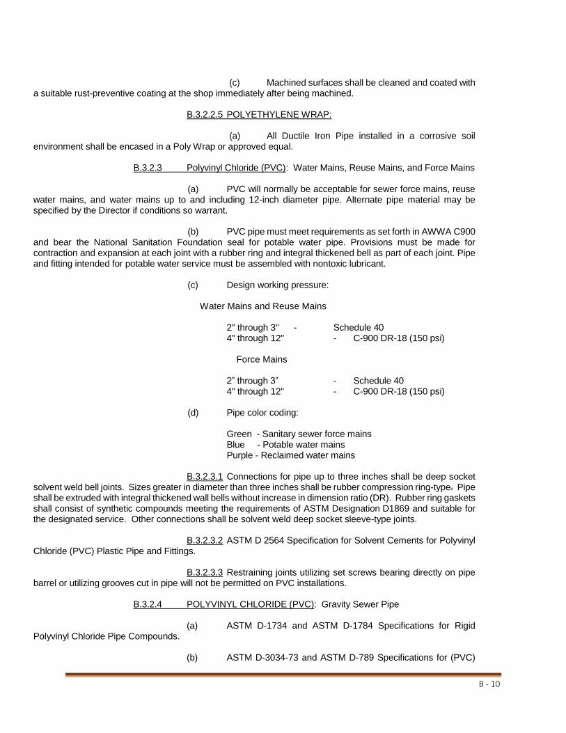
B - 10
(c) Machined surfaces shall be cleaned and coated with a suitable rust-preventive coating at the shop immediately after being machined. B.3.2.2.5 POLYETHYLENE WRAP: (a) All Ductile Iron Pipe installed in a corrosive soil environment shall be encased in a Poly Wrap or approved equal. B.3.2.3 Polyvinyl Chloride (PVC): Water Mains, Reuse Mains, and Force Mains (a) PVC will normally be acceptable for sewer force mains, reuse water mains, and water mains up to and including 12-inch diameter pipe. Alternate pipe material may be specified by the Director if conditions so warrant. (b) PVC pipe must meet requirements as set forth in AWWA C900 and bear the National Sanitation Foundation seal for potable water pipe. Provisions must be made for contraction and expansion at each joint with a rubber ring and integral thickened bell as part of each joint. Pipe and fitting intended for potable water service must be assembled with nontoxic lubricant. (c) Design working pressure:
Water Mains and Reuse Mains 2" through 3" - Schedule 40 4" through 12" - C-900 DR-18 (150 psi) Force Mains 2” through 3” - Schedule 40 4" through 12" - C-900 DR-18 (150 psi) (d) Pipe color coding: Green - Sanitary sewer force mains Blue - Potable water mains Purple - Reclaimed water mains B.3.2.3.1 Connections for pipe up to three inches shall be deep socket solvent weld bell joints. Sizes greater in diameter than three inches shall be rubber compression ring-type. Pipe shall be extruded with integral thickened wall bells without increase in dimension ratio (DR). Rubber ring gaskets shall consist of synthetic compounds meeting the requirements of ASTM Designation D1869 and suitable for the designated service. Other connections shall be solvent weld deep socket sleeve-type joints. B.3.2.3.2 ASTM D 2564 Specification for Solvent Cements for Polyvinyl Chloride (PVC) Plastic Pipe and Fittings. B.3.2.3.3 Restraining joints utilizing set screws bearing directly on pipe barrel or utilizing grooves cut in pipe will not be permitted on PVC installations. B.3.2.4 POLYVINYL CHLORIDE (PVC): Gravity Sewer Pipe (a) ASTM D-1734 and ASTM D-1784 Specifications for Rigid Polyvinyl Chloride Pipe Compounds. (b) ASTM D-3034-73 and ASTM D-789 Specifications for (PVC)

B - 11
Plastic Pipe (SDR-35 and SDR-26) Bell and Spigot. (c) ASTM D-3212 flexible gasketed joints for PVC sewer compres-sion-type. The gasket shall comply with ASTM F-477. B.3.2.5 POLYETHYLENE PLASTIC SERVICES: Water and Reuse (a) All main line taps to be made using double strap cast iron ser-vice saddles with epoxy coating. (b) Corporation stops to be provided with all service saddles and taps. (c) All one-inch service lines to be of 200 psi rated type III, Grade 34, Class C, PE 3408 Polyethylene Tubing made of virgin quality polyethylene. Material shall have no failures after 5000 hours testing in accordance with ASTM D-1693, Condition C. Tubing shall be CTS size, SDR9. (Driscopipe 5100 ULTRA-LINE or Vanguard Manuf.) Double Services and road crossings to be 1-inch tubing. Single same-side services may be 1" tubing of same specification. (d) All one-inch service lines crossing under any road rights-of-way or permanently paved or concreted areas to be provided with a two-inch Schedule 40 or SDR 21 PVC casing. Casing to extend a minimum of two feet on either side of pavement extend beyond the limits of sidewalks if applicable. Minimum size for polyethylene services crossing roadways shall be one-inch. Single service crossovers for 3/4" meters will be reduced before the meter. (e) One-inch double service lines to terminate in a 3/4-inch X 3/4-inch X 1-inch compression brass wye with parts interchangeable with Ford Pak-Joint fittings. (f) All service "pigtails" to be 3/4” poly tubing (Driscopipe 3408 or equivalent) four foot in length terminating at property line corners. (g) All "pigtails" to be provided with 3/4-inch brass ball valves with locking wings. Ball valves to be 3/4 CTS compression X 3/4-inch meter coupling compatible with Ford Pak-Joint. Curb Stop connection shall be an integral part of the ball valve. (h) All fittings and stops to be of high quality water works brass. No PVC fittings or adapters will be permitted. (i) Pipe or tubing shall comply with AWWA C901, D-2239 (Pipe), and D-2737 (Tubing), be approved for potable water service by the National Sanitation Foundation, and bear the NSF seal. The product shall be rated for a minimum working pressure of 150 psi. Fittings shall be brass, equipped with compression-type connections, "Pak-Joint", as manufactured by Ford Meter Box Co., Wabash, Indiana, or approved equal. Must be compatible with existing equipment. B.3.2.6 SPECIAL ITEMS: B.3.2.6.1 EXPANSION JOINTS: Pipe expansion joints shall be suitable for the applicable service with a minimum 150 psi working pressure and shall be Style No. 500, as manufactured by Mercer Rubber Company, or approved equal. B.3.2.6.2 FLANGED COUPLING ADAPTERS: Units shall be as manufactured by Nappco Baker, Ontario, California, or approved equal, with Type 601, for pipe sizes to 12 inches; and Type 602, for larger sizes; and shall be compatible with ANSI Standard B16.1, 125 lb. flanges. B.3.2.6.3 CAST COUPLINGS: Units shall be as manufactured by Nappco Baker, Ontario, California, or approved equal, as follows: Type 228 (connecting equal outside diameter

B - 12
pipes); Type 236 (reducing coupling). Gaskets shall be suitable for the applicable service conditions. B.3.2.6.4 SLEEVES AND WALL PIPES: Units shall have integral annular ring water-stops, and also conform to other requirements for cast iron fittings specified in this section. Sleeves and wall pipes to have laying length and ends required for proper installations shall be "Link-Seal" or equal. B.3.2.6.5 TAPPING SADDLES: Units shall be fabricated of ductile iron or epoxy-coated steel with stainless steel hardware and suitable for either wet or dry installation and shall be as manufactured by Nappco Baker, Ontario, California, or approved equal. The sealing gasket shall be the "O"-Ring type suitable for the applicable service. Tie straps and bolts shall be Stainless Steel. B.3.2.6.6 TAPPING SLEEVES: Units shall be as manufactured by Romac Industries, Inc. Seattle, Washington. Tapping sleeves shall be of 304 stainless steel and shall provide a full circumferential seal. Full circle tapping sleeves shall be used on all size-on-size taps as well as existing AC pipes and class 200 pipe. B.3.2.6.7 SERVICE SADDLES: Saddles shall be as manufactured by Nappco Baker, Ontario, California, or approved equal. Saddles shall be double strap. Sealing gaskets shall be suitable for the applicable service and straps shall be corrosion resistant alloy steel. B.3.3 VALVES: B.3.3.1 GENERAL: The valve type, size, rating, flow direction arrow, if applicable, and manufacturer shall be clearly marked on each unit. Valves shall open left (counterclockwise), with an arrow cast in the metal of operating hand wheels and nuts indicating the direction of opening. B.3.3.2 GATE VALVES (GV): B.3.3.2.1 UNDERGROUND SERVICE (GENERAL): Valves two inches and larger shall be iron body, bronze-mounted, conforming to AWWA C509, resilient wedge, non-rising stem-type, and consist of an encapsulated disc with elastomer seat upon a cast iron body resulting in a bubble-tight seal at full differential pressure of 200 psi and shall be equipped with two-inch square cast iron wrench nuts. Valves four inches and over shall be mechanical joint connections. Valves shall be Kennedy 1571X or approved equal. B.3.3.2.2 ABOVEGROUND SERVICE (GENERAL): Valves shall be iron body, bronze-mounted resilient wedge gate valves, conforming to AWWA C-509. Valves shall have cast aluminum or cast iron hand wheels or chain operators with galvanized steel chains, as required. B.3.3.2.3 TAPPING VALVES: Valves shall conform to the specifications set forth under Paragraphs B.3.3.2.1 and B.3.3.2.2 (preceding), for the applicable service conditions. Additionally, units shall be comparative with the connecting sleeve or saddle and specially designed for wet tapping installation operations. B.3.3.2.4 VALVES LESS THAN TWO INCHES: Valves shall be bronze, wedge disc, non-rising stem-type, and 200 psi minimum working pressure, equipped with ductile iron operating hand wheels. Valves shall be Hammond IB645 or approved equal.

B - 13
B.3.3.2.5 ACTUATORS: Valves 18 inches and larger shall be equipped with approved gearing actuators, with sealed enclosures for buried or submerged service, and shall be furnished by the valve manufacturer. Position indicators shall be furnished as required. B.3.3.3 CHECK VALVES (CV): B.3.3.3.1 GENERAL SERVICE: Water valves shall be iron body, bronze-mounted, stainless steel hinge pin, outside lever and spring operated, swing nonslam-type, and equipped with removable inspection covers. Units shall be rated for 200 psi minimum working pressure and shall permit full flow area equal to that of the connecting pipe. Valves shall be as manufactured by Kennedy Valve Co., or approved equal. Sewer valves shall be lever and weight type. B.3.3.3.2 CHECK VALVES TWO INCHES AND SMALLER: Valves shall be bronze body and disc, swing check-type, with removable inspection covers, and rated for 200 psi minimum working pressure. B.3.3.4 PVC BALL VALVES: Polyvinyl chloride (PVC) ball valves shall be provided, as required, for chemical service installations and shall be full port area, No. 8903, as manufactured by Walworth Company, or approved equal. B.3.3.5 CORPORATION STOPS AND CURB STOPS: Units shall be brass, equipped with connections compatible with the connecting service pipe-type; must have pack joint type connections for polyethylene tubing with locking collars. These stops shall have a teflon coated ball valve such as the "pak-joint" valve manufactured by Ford Meter Box Co., Wabash, Indiana. These items must be compatible with existing equipment. B.3.3.6 SLUICE GATES: Gates and appurtenances shall comply with the pro-visions of AWWA Standard C501, "Sluice Gates". Type of gate design, materials of construction, method of operation, and other special considerations shall be as required for the specific installation and service condition. B.3.3.7 AIR RELEASE VALVES – AIR AND VACUUM VALVES: B.3.3.7.1 SEWER SERVICE: Automatic Air Release Valves shall be Model S-020 and Air/Vacuum Valves Model K-020 Manufactured by A.R.I.(7928 Sebago Court Orlando, FL 32835) or approved equal. Valves shall have a minimum inlet size of two inches. B.3.3.7.2 WATER SERVICE (VENT ONLY): Valves shall be cast iron body, suitable for domestic water service, rated for a minimum 150 psi working pressure, equipped with a vacuum ball to prevent air return, and shall be as manufactured by Valve and Primer Corporation, Chicago, Illinois, or approved equal, shall be Model No. 200 series, sized appropriately for the application. Valves shall have a minimum inlet size of one inch. B.3.3.8 SPECIAL ITEMS: B.3.3.8.1 VALVE BOXES: Units shall be adjustable, ductile iron, slip-type, minimum interior diameter of five inches, with covers cast with the applicable inscription in legible lettering on the top: "SEWER", "WATER", "REUSE", and shall be of the color specified in Paragraph B.3.2.1. Boxes shall be suitable for the applicable surface loading and valve size, and shall be as manufactured by CDR Corporation, M & H Valve and Fitting Company, U.S. Foundry and Mfg. Corporation, or approved equal. B.3.4 INSTALLATION: B.3.4.1 GENERAL REQUIREMENTS: B.3.4.1.1: Piping, fittings, valves, and appurtenances shall be installed in

B - 14
accordance with these Standards and in general with the manufacturer's recommendations for the applicable service. B.3.4.1.2: Piping shall be installed along straight line and grade between fittings, manholes, or other defined points, unless other definite lines of alignment deflection or grade change have been established. Modification to approved alignment or grade during construction shall receive prior approval from the Engineer and all resulting design conflicts shall be resolved by the Engineer prior to proceeding. Pipe joint deflection shall not exceed the manufacturer's recommendation. B.3.4.1.3: Materials shall be cleaned and maintained clean, with all coatings protected from damage. The interior of the pipe shall be free of dirt and debris, and when work is not in progress; all open ends shall be plugged. B.3.4.1.4: Pipe, valves, fittings, or other items shall be inspected prior to installation and any items showing a fracture or other defect shall be rejected. Additionally, any pipe or fitting which has received a severe blow that may have caused an incipient fracture, even though not visible, shall also be rejected. However, ductile iron pipe showing an end crack, with no fracture indicated beyond that visible, may be salvaged by cutting off the damaged section 12 inches past, providing the remaining pipe is sound. B.3.4.1.5: Underground piping shall not be driven to grade by striking it. When the pipe has been properly bedded, enough compacted backfill shall be placed to hold the utility in correct alignment. If necessary, precaution shall be taken to prevent flotation. B.3.4.1.6: Jointing shall be by the manufacturer's approved method and shall not require undue force to accomplish full satisfactory seating and assembly. Connections at structures shall be cut accurately and worked into place without forcing and shall align with the connecting point. “Home line” shall not be pushed beyond plain sight when pipe is homed into the bell. Flanged joints shall be made up tight, but with care taken to prevent undue strain upon equipment or other items. Suitable flange filler rings shall be installed where required to provide suitable joints. The installation shall be permanently watertight, with no visible leakage at joints, connections with structures, or other locations, under operational or testing conditions. Material that in jointing does not remain completely seated and/or watertight shall be rejected. B.3.4.1.7: Underground pressure piping systems shall be thoroughly restrained with approved restraining devices such as Mega-Lugs, Uni-Flanges, etc. Pipe shall be restrained for 40' each way from 45o ells, and 60 feet in each direction from 90o ells, tees, and plugs for pipe up to 12”. Restraint distances for pipe over 12” will be determined by the engineer. Concrete thrust blocks will not be accepted. B.3.4.1.8: Exposed systems shall be supported as necessary to hold the piping and appurtenances in a firm, substantial manner to the required lines and grades indicated, with no undue piping stresses transmitted to equipment or other items. Piping within buildings shall be adequately supported from floors, walls, ceilings, or beams. Supports from the floor shall be by suitable saddle stands or piers. Piping along walls shall be supported by satisfactory wall brackets, or saddles, or by wall brackets with adjustable hanger rods. For piping supported from the ceiling, approved rod hangers of a type capable of screw adjustment after erection of the piping shall be used. Pipe aboveground outside of buildings shall be supported on concrete supports or pre-manufactured adjustable pipe supports. B.3.4.1.9: Proper provision for pipe expansion or contraction shall be pro-vided by installation of expansion joints or other suitable methods. Additionally, flexible connections shall be provided to expedite equipment or piping system removal. B.3.4.1.10: Sub aqueous pipe laying may be permitted where conditions make it impractical to lay pipe "in the dry", provided the Contractor submits his plans for laying pipe under water to the Engineer and obtains advance approval thereof. All sub aqueous crossings shall be made in accordance with all approved permits.

B - 15
B.3.4.1.11: Installation of Fire Line mains for water and reclaim distribution shall be constructed with a minimum of 8” diameter pipe. B.3.4.2 DUCTILE IRON (DI) PIPE: Installation shall be performed in accordance with the applicable provisions of AWWA Standard C600. The opening cut in the pipe wall for installation of tapping saddles and sleeves shall be made by a special tapping machine designed for this specific service. All pipe cutting shall be accomplished by power-operated abrasive wheel or saw cutters, or other methods approved by the pipe manufacturer. Where required, Polyethylene Encasement shall be installed as set forth under AWWA C105. B.3.4.3 POLYVINYL CHLORIDE (PVC) PIPE: Lubrication and/or solvent used for pipe and fitting joints shall be nontoxic (NSF approved for potable water). Following making, solvent-type joints shall not be disturbed for five minutes and shall not have internal pressure applied for 24 hours, or as recommended by the pipe manufacturer. B.3.4.4 STEEL PIPE - GALVANIZED (GS) AND BLACK (BS): Threaded ends shall be connected as specified under the applicable provisions of AWWA Standard C202, with exposed threads of underground galvanized piping protected with two coats of bituminous paint prior to backfilling. Required welding shall be as specified in AWWA Standard C206. Flanged connections shall be installed in accordance with AWWA Standard C207. The exterior of underground black steel pipe shall be protected by coating and wrapping as specified under AWWA Standard C203, or other methods receiving prior approval from the Director. B.3.4.5 Valves: B.3.4.5.1 GENERAL: Valves shall be carefully inspected, opened wide, and then tightly closed, and all the various nuts and bolts thereon shall be tested for tightness. Special care shall be taken to prevent joint materials, stones, or other substances from becoming lodged in the valve seat. Valves, unless otherwise required, shall be set with their stems vertically above the centerline of the pipe. Any valve that does not operate correctly shall be adjusted to operate properly or removed and replaced. B.3.4.5.2: Buried valves shall be installed vertically where depth of cover permits. Where depth of cover does not permit, the valves shall be mounted horizontally and provided with 90-degree adapters to allow vertical operation. Extension stems shall be provided on all buried valves when the operating nut is deeper than three feet below the final grade, with sufficient stem extension to place the nut not more than two feet below grade. Where extension stems are required within valve boxes, approved insert stem guides shall be provided and attached securely to valve operating nut. All valve locations to be marked on the roadway or curb with a neatly painted four-inch by six-inch stripe. Curb shall be scored with a power saw prior to painting. Paint shall be of a type recommended for exterior concrete surfaces. Color shall correspond to the requirements of Section B.3.2.1. B.3.4.5.3: Valve boxes shall be carefully centered over the operating nuts of underground valves to permit a valve wrench to be easily fitted to the nut. Valve Box centering spacers such as made by American Flow Control (B59434 and B59435) or equivalent shall be used. The tops of valve boxes shall be set to the required grade. Valve box adjustment risers may be used, where it is acceptable and/or as required by the City. The valve box shall not transmit surface loads directly to either the pipe or valve. Care shall be taken to prevent earth and other material from entering the valve boxes. Any valve box that becomes out of alignment or is not to grade shall be dug out and adjusted. Concrete pads will be provided around boxes, two feet by two feet by six inches, with data plates providing information as to valve type and size. B.3.4.5.4: Where floor stands and/or extension stems are required for exposed valves, adjustable wall brackets and extension stems shall be furnished. Brackets shall not be more than six feet apart, unless otherwise approved by the Engineer with floor stands and guides set so that the stems shall run smoothly and in true alignment. Stands and guides shall be firmly anchored to the concrete.
SECTION B.4

B - 16
GENERAL PROVISIONS
B.4.1 GENERAL: The provisions of this section shall be applied, where relevant, to all water, wastewater and reclaimed water facility installations, where City of New Port Richey is the owner. B.4.2 RELATED STANDARDS: The technical requirements included within Division B shall be applicable to all water, wastewater and reclaimed water facility construction and/or modification, unless specifically indicated otherwise within Divisions C, D, and E. B.4.3 GENERAL REQUIREMENTS: B.4.3.1 EQUIPMENT INSTALLATION: All equipment shall be installed satis-factorily and properly for the specified service, and in accordance with the manufacturer's recommendations. All required piping, electrical connections, and other necessary items shall be furnished and connected in order to provide a complete operating facility. B.4.3.2 MODIFICATIONS TO EXISTING EQUIPMENT: Should modifications to existing City equipment be required in order to achieve the required operational facility, the Engineer shall coordinate all designs and construction procedures with the NPRPWD and receive advance approval therefrom. Additionally, the Engineer shall consult with, and obtain the written recommendations of, the existing equipment manufacturer regarding any such modifications, and include all such information in the approval presentation. B.4.3.3 SALVAGE: Existing equipment and materials that are to be removed during the course of modification work, including pumps, motors, and pump parts; pipe, valves, and fittings; electrical and control parts; and other salvageable items, shall remain the property of City of New Port Richey. The Contractor shall be responsible for transporting salvaged items to the storage area designated by the City. Special care shall be taken for the protection and elimination of damage to said items. Material shall be cleaned prior to delivery to the City. If determined by the NPRPWD staff that the salvaged materials are of no use or value to the city it shall be the contractors’ responsibility to dispose of the materials in accordance with local regulatory requirements. B.4.3.4 EQUIPMENT OPERATING TESTS: Following the installation and final adjustment, all equipment shall be test operated under normal and full load conditions for a period of not less than two hours. Any faults or deficiencies that may appear shall be promptly corrected and the system retested for satisfactory operation. The tests shall be performed in the presence of the authorized representative from the NPRPWD and the Project Engineer. After completion of unit operating tests, the completed facility shall be placed "on stream" and tested in operation under normal conditions for a period of not less than five days to test the suitability of each type of equipment and control, and to demonstrate that each item was properly installed, adjusted, and is functioning in accordance with requirements. During this period, the Contractor shall instruct designated employees of the City in the proper care, operation, and maintenance of all equipment and materials. The Contractor shall furnish all electricity, gas, lubricants, water, and other materials required to make tests and shall replace or repair all material or equipment found to be defective or deficient. Timing and performance of tests shall be coordinated with the NPRPWD. B.4.3.5 MANUFACTURER SUPERVISION: The Contractor shall require manu-facturers furnishing primary equipment to provide the services of a qualified technical representative for such periods as are necessary to supervise proper installation; perform final adjustments and testing for the operational system; and instruct operating personnel in the use of the equipment. The manufacturer shall certify in writing to the NPRPWD as to the correct installation and operation of their equipment. B.4.3.6 OPERATING INSTRUCTIONS AND PARTS LISTS: The Contractor shall furnish, for each piece of operating equipment, three complete, neatly bound sets and digital .PDF format giving the information listed below:

B - 17
(a) Clear and concise instructions for the operation, adjustment, and lubrication and other maintenance of the equipment. These instructions shall include a complete lubrication chart. (b) List of all parts for the equipment, with catalog numbers and other data necessary for ordering replacement parts. (c) All warranty information for the materials or devices and contact information for requesting warranty work or service.

DIVISION C
SANITARY SEWER FACILITIES

C - 1
SECTION C.1
SANITARY GRAVITY SEWERS C.1.1 GENERAL: C.1.1.1 This section includes general technical criteria for the design and instal-lation of sanitary gravity sewer systems. Plans and specifications and engineering reports shall be prepared in accordance with the minimum and applicable provisions of the Recommend Standards for Wastewater Facilities (RSWF). The plans and specifications or engineering report shall be signed and sealed by a Professional Engineer registered in Florida. C.1.1.2 The relevant provisions included in Division B, "Technical Require-ments - General", and shown on "Standard Details - Sanitary Sewerage Systems" and "Standard Location Plan - Underground Utilities" shall be applicable to this section, unless otherwise indicated herein or changed in writing by the Director. C.1.2 DESIGN STANDARDS: C.1.2.1 REQUIRED REFERENCE: The Contractor shall comply with the appli-cable requirements specified within the New Port Richey, Florida, Land Development Code, and as established by the FDEP Rules and regulations. The criteria set forth in Chapter 20, "Design of Sewers", of the "Ten State Standards - Recommended Standards for Sewage Works" shall be used as a design guide. Conflicts will be brought to the attention of the Director. C.1.2.2 SYSTEM DESIGN: C.1.2.2.1 AVERAGE DESIGN FLOWS: The sewer system design shall be based on full ultimate development as shown in the following table:
Design Flow - Residential Estimated Flow Single-Family Unit - Normal 3br/2bath 250 gpd Single-Family Unit - Retirement subdivision 170 gpd Multi-Family Unit - Normal type 170 gpd Multi-Family Unit - Retirement subdivision 220 gpd The average daily flow (ADF) from domestic units shall be calculated at the minimum rate of 100 gallons per capita per day (gpd), which will normally cover infiltration; but should conditions be unfavor-able, an additional allowance shall be included. Flow requirements from commercial, industrial, institutional, or other special development areas shall be established from existing records, or by estimated projections using the best available data; however, in no case shall a rate of less than 1,000 gallons per acre per day be used, unless specifically approved otherwise. The progressive summation of the previously described contributions shall constitute the ADF for specific sections of the sewer system. C.1.2.2.2 PEAK DESIGN FLOWS: Gravity sewer systems shall be designed on the basis of ultimate development maximum rates of flow, which will be the product of selected peak factors times the accumulative Maximum Monthly Average Daily Flow (MMADF) for the subject portion. In general, the following peak factors shall be applicable for the range of average daily flow rates indicated (million gallons per day - mgd), unless larger values are required for specific conditions or prior approval is received from the Engineer for modification thereof.
FLOW RANGE (MMADF), MGD PEAK
FACTOR
-- to 0.100 3.8
0.101 to 0.250 3.5

C - 2
0.251 to 1.000 3.0
1.001 to 4.000 2.4 C.1.2.2.3 SEWER SIZE COMPUTATION: Sanitary sewers shall be sized to provide ample capacity for the required peak flow rates. The minimum allowable size for any sewer, other than service connections, shall be eight inches in diameter. All sewers shall be designed at slopes providing minimum velocities of not less than two feet per second when flowing full or half full. Said computation shall be based on Kutter's Formula, using a roughness coefficient ("N") of not less than 0.013, unless justifiably approved otherwise. In general, the following minimum slopes shall be provided for sewer sizes to 24 inches:
SEWER SIZE (INCHES)
MINIMUM SLOPE, % (FEET PER 100 FEET)
8 0.4
10 0.28
12 0.22
14 0.17
15 0.15
16 0.14
18 0.12
20 0.11
21 0.1
24 0.08 C.1.2.2.4 DESIGN CONSIDERATIONS: (a) Sewer pipes 24 inches in diameter or less shall be installed with straight alignment and grade between manholes, with manhole spacing not to exceed 400 feet. (b) All sanitary sewer pipes shall terminate at manholes. (c) Sewer pipes of diverse sizes shall always join at manholes, with no size conversions between. Where different sizes join, the pipes shall be placed at elevations where the depth points are equal, unless higher points are required. If the entrance pipe elevation exceeds two feet above the effluent sewer, drop manhole connections shall be provided. (d) Flow direction changes in excess of 90 degrees within manholes shall not be permitted. When directional changes exceed 45 degrees, an extra flow line elevation drop (0.1'±) across manholes shall be provided. (e) Where design velocities greater than 15 feet per second are attained, due to topography or other reasons, special equipment shall be provided for sewer protection, as approved by the Director. (f) Minimum size of gravity main is eight inches; minimum slope for an eight-inch main is 0.40 percent. C.1.3 STANDARD REQUIREMENTS: C.1.3.1 GENERAL: The materials of construction and general installation proce-dures shall comply with the specific applicable standards set forth under Section B.1, "Utility Excavation,

C - 3
Trenching, and Backfilling", Section B.2, "Casing Pipe - Boring and Jacking", and Section B.3, "Pipe, Fittings, Valves and Appurtenances", as well as the Standard Details section. C.1.3.2 APPROVED PIPE: The types tabulated below, with the restrictions indi-cated, are approved for sanitary gravity sewer construction:
PIPE AND FITTINGS RESTRICTIONS
DUCTILE IRON (DI) PIPE (CL-150) & REQUIRED AT INVERTS
FITTINGS - INTERIOR 401 - EPOXY COATING BELOW 18 FEET
PLASTIC SEWER (PVC) - SDR-35 ALLOWED AT INVERTS 0-12 FEET
PLASTIC SEWER (PVC) - SDR-26 MAY BE USED 12-18 FEET C.1.3.3 SANITARY SEWER MANHOLES: C.1.3.3.1 Manholes shall be precast concrete, as detailed. Alternate manhole materials and designs shall receive prior approval from the Engineer. The minimum inside diameter of manholes shall be 48 inches for sewer sizes to 21 inches in diameter or less, with submittal of special designs for larger pipes. C.1.3.3.2 Precast reinforced manholes shall be in accordance with ASTM Designation C478, with preformed flexible plastic joint sealer conforming to Federal Specification SS S-00210 - (GSA-FSS), "Ram-Nek", as manufactured by the K. T. Snyder Company, Inc., Houston, Texas, or approved equal. Installation of precast manholes shall comply with the details shown on "Standard Detail Sheets" and in accordance with the manufacturer's recommendations. C.1.3.3.3 Manhole frames and covers shall be grey cast iron or ductile iron heavy-duty conforming to ASTM Designation A48, Class 30, and shall be U.S. Foundry and Manufacturing Corp., or approved equal. Covers shall have no perforations and shall be marked with the word "SANITARY". Sewer frames and covers shall be fully bedded in mortar to the correct finish grade elevation, with adjustment brick courses placed below, as detailed, for precast manholes. Frames shall be suitable for the future addition of cast iron rings for upward adjustment of top elevation. All frames and covers shall meet HS20-44 load requirements. C.1.3.3.4 Manhole flow channels shall be as shown on the "Standard Detail Sheets" with smooth and carefully shaped bottoms, built-up sides and benching constructed from concrete. Channels shall conform to the dimension of the adjacent pipe and provide changes in size, grade, and alignment evenly. C.1.3.3.5 The interior surfaces of all manholes shall be protected by the application of Spectraguard by Concrete Conservation, Inc. This includes walls, chimneys, floors, benches, invert channels, lids, and all joints after grouting. Exterior surfaces shall receive two coats of Koppers Bitumastic Black Solution, or approved equal, for moisture protection, applied at a minimum rate of 375 sq. ft. per gallon per coat. Surface preparation and paint application shall comply with the manufacturer's recommendations. C.1.3.3.6 Where additional pipe connections or modification of existing factory-made openings are required on new or existing pre-cast concrete manholes, all cutting relative thereto shall be performed only by abrasive wheel saw. It is specifically noted that such connections to existing manholes shall be installed in accordance with the details for new units shown on "Standard Detail Sheets" and shall be sleeved and caulked watertight with non-shrinking grout. C.1.3.3.7 Manholes shall be designed and constructed within road

C - 4
rights-of-way and shall be specifically located either in the pavement or within four feet of the edge of curb. In no case will manholes be located within backyard easements or any location not readily accessible to maintenance vehicles and equipment. C.1.3.4 TERMINAL LAMPHOLES: Lampholes shall not be allowed. C.1.3.5 PIPE DEPTH AND PROTECTION: The minimum allowable cover for gravity sewers shall be three feet from the top of the pipe to finish grade. However, should this depth not be feasible, where grade depressions along the alignment are unavoidable, protective concrete slabs shall be provided over the pipe and/or ductile iron or C-900 PVC pipe shall be installed within the limits of the lesser cover. In no case shall pipe cover be less than 18 inches, unless special design considerations have been approved by the Engineer. Where navigable waterways are crossed, ductile iron pipe shall be installed across and to ten feet each side of the bottom. Additionally, approved utility crossing signs shall be placed on the pipe alignment at each side of the waterway. Sign shall be approved by the NPRPWD. C.1.3.6 PIPE BEDDING: Special care shall be exercised in design and installation to provide adequate bedding for the type of pipe used, taking into consideration trench width and depth, superimposed loadings above grade, and the material below trench grade. Pipe loading capabilities shall be computed in accordance with established design criteria and special supporting bedding or facilities shall be provided as required by the Engineer (see Section B.1.3). C.1.3.7 SPECIAL EXTERIOR PROTECTION FOR CORROSION: Extra protection shall be provided for underground cast or ductile iron pipe and fittings within areas of severe corrosive conditions. This shall be accomplished by the installation of polyethylene encasement, as specified in Section B.7, through the area of concern. The soil test evaluation to determine the necessity for extra protection in suspect areas shall be as set forth in ANSI Standard A21.5. Additionally, where other existing utilities are known to be cathodically protected, cast or ductile iron pipe crossing said utility shall be protected for a distance of 20 feet to each side; and when installed parallel to and within ten feet of same, protection shall also be provided. C.1.3.8 CONNECTIONS AT STRUCTURES: Where sanitary sewers connect to structures, pipe joints shall be provided at the wall face. When it is necessary to extend sewers through structures, such as conflicting elevation storm drain bypassing chambers, the pipe within shall be ductile iron with no inside joints. "Link-Seal" or equal shall be used at all wet well and wall penetrations. C.1.3.9 TRANSITION CONNECTIONS: Where pipes of alternate materials (VC to CI, etc.) are to be connected between manholes, suitable approved transition couplings shall be installed. Couplings shall be "Fernco" as manufactured by Fernco Inc., Davison, Mich., C-T Adapters" as manufactured by Can-Tex Industries, Mineral Wells, Texas, or approved equal. Special designed units may be submitted for approval; however, concrete collars are not acceptable. C.1.3.10 PIPE CUTTING: The cutting of ductile iron pipe for installation length adjustment, or connections for future services to existing sewers, shall be in strict compliance with the methods specified in AWWA C600. C.1.3.11 SERVICE CONNECTIONS: Service laterals will not empty directly into manholes. Installation shall be as shown on Detail Sheet "Service Connection Details"; including the wye branches installed in the sewer main at the point of connections, and the service pipe and required fittings extend to the property line, perpendicular to said line, terminating with plugged ends or fittings, as indicated. The mini-mum service pipe size shall be four inches in diameter for a single service and six inches in diameter for a double service. On curbed streets, the exact location for each installed service shall be marked by painting a two-inch by four-inch green stripe on the concrete curb. Paint shall be of a type recommended for exterior concrete. Curb shall be scored with a power saw prior to painting. Where no curb exists or is planned, locations shall be adequately marked by a method approved by the NPRPWD. The end of the service lateral shall be marked with a two-inch by four-inch wooden stake or a two- inch PVC stake extending three feet aboveground

C - 5
and painted green. Service lines to building shall conform to the local Plumbing Code. All service connections between city maintained facilities and the lines to the building shall have a cleanout installed at the property line for maintenance access. The clean out shall be a “Double Sweep” configuration and shall be sized based on the type of service lateral installed; 4” for Single Services and 6” for Double Services. The top of all cleanout assembly’s shall be set at a grade 2” above the surrounding area. Any cleanout installed within an area where vehicle traffic or equipment loading is possible shall be installed with a Steel Ring and Cover and Concrete Pad. C.1.4 TESTING: C.1.4.1 The Contractor shall perform testing of all sanitary gravity sewers, as set forth in the following, and shall conduct said tests in the presence of representatives from the NPRPWD with two days' advance notice provided. C.1.4.2 The installed gravity sewers shall be "lamped" between manholes or other structures in order to ascertain that they are clear and in correct alignment. The concentricity of the lamp image received shall be such that the diameter of said image shall have no vertical reduction from that of the pipe inside diameter and not more than 20 percent horizontal reduction. Testing shall not proceed until all facilities are complete in place and concrete cured. All piping shall be thoroughly cleaned prior to testing to clear the lines of all foreign matter. Lines shall be flushed with water prior to lamping to aid in the detection of dips in the line. Lines which have dips which retain greater than one inch of water may be subject to repair at the discretion of the NPRPWD. C.1.4.3 TELEVISION INSPECTION: New gravity sewer mains shall be television inspected at the expense of the contractor. Videos shall be furnished on a DVD format, in color, and of suitable clarity and quality for good definition. All television inspections shall also include log sheets depicting manhole locations including manhole or structure numbers which correspond to the numbering system used in the plan set. All television logs shall include accurate measurements to each service tap taken from the center of the manhole structure. All lines shall be flushed with water immediately prior to the television inspection in order to identify Dips, or Elevation problems with the line. C.1.4.4 DEFLECTION TESTING: New gravity sewer mains are subject to deflection testing at the discretion of the NPRPWD. Tests will be conducted using a 92.5 percent mandrel. The mandrel shall be pulled through the sewer line by hand, using a 150-pound test line. If the mandrel cannot traverse the pipe as such, then the deficiency must be corrected. The intent is to require testing of lines which appear to be defective or otherwise unsatisfactory. C.1.4.5 SMOKE TESTING: New gravity sewer mains may be smoke tested by the NPRPWD at the discretion of the NPRPWD. Any defects detected as a result of the testing shall be promptly repaired by the Contractor. C.1.4.6 RECORD DRAWINGS “AS-BUILT”: New Gravity Sewer, Force Main Sewer and Lift Stations shall not receive final acceptance by the NPRPWD until accurate approve Record Drawing “As-Built information is received. These documents must include accurate drawings of the utilities installed including but not limited to: Field changes such as additional fittings installed during construction, measurements from edge of pavement or other fixed location to the new utility, Conflict resolutions made in the field, Actual distanced of pipe between Manholes. Actual measurements for service taps both at the main tap and the termination point at the edge of the ROW or Easement taken from the center of manhole structures, all final elevations for utilities installed. These documents shall be provided as Full Plan Sets and Marked “Record Drawings” The documents shall be sealed by a certified land surveyor. A minimum of (3) Full plan sets shall be supplied to the city for review. Electronic copies shall also be provided in both CAD format and 256 Grey Scale Compressed JPG.

C - 6
SECTION C.2
SANITARY SEWER FORCE MAINS C.2.1 GENERAL: C.2.1.1 This section includes the general requirements for design and installation of force main systems serving sanitary sewer pumping stations. C.2.1.2 The relevant provisions set forth in Division B, "Technical Requirements", and shown on "Standard Details - Sanitary Sewer Systems" and "Standard Location Plan - Underground Utilities" shall be applicable to this section unless otherwise indicated herein or approved by the Director. C.2.2 DESIGN STANDARDS: C.2.2.1 REQUIRED REFERENCE: The Contractor shall comply with the applic-able design and installation requirements as specified within the Pasco County Land Development Code, and as established by the FDEP Rules and Regulations. C.2.2.2 SYSTEM DESIGN: Force main systems shall be either six inches or eight inches in diameter (unless specifically approved by the NPRPWD on an individual basis) and of adequate size to efficiently transmit the total ultimate peak operational flows, applied by the connected sewage pumping station(s), to the point of discharge. Consideration shall be given to possible future connecting pumping stations and this probability shall be reviewed with the NPRPWD. Capacity computations shall be coordinated with the proposed pumping systems(s), along with any future flow requirements, if applicable. In order to provide ade-quate pipeline cleansing, force main flow velocity shall not be less than two feet per second at ultimate design minimum pumping capacity; however, with multiple pumping station systems or phase development, this requirement may not be possible and the system design shall receive special attention regarding cleaning main-tenance. C.2.2.3 OPERATIONAL COST CONSIDERATIONS: For Type II and Type III lift stations (see Section C.3, Paragraph C.3.4), in addition to initial capital expenditure, long-term pumping station operational costs shall also receive consideration when sizing force main systems. Should a pipe size option be available within the design limits, the cost of sewage pumps and motors, force main system, and pump operating power (computed for design average daily flow rate for ten years at existing electricity cost) shall be compared to like amounts for the alternate designs. The final force main size selection shall be directed towards the system with the least long-range capital and operational cost. Said cost analysis shall be subject to review by the NPRPWD. C.2.3 STANDARD REQUIREMENTS: C.2.3.1 GENERAL: The materials of construction and general installation proce-dures shall comply with the specific applicable standards set forth under Section B, "Utility Excavation, Trenching, and Backfilling", "Casing Pipe - Boring and Jacking", and "Pipe, Fittings, Valves, and Appurte-nances", as well as "Standard Details - Sanitary Sewer Systems".
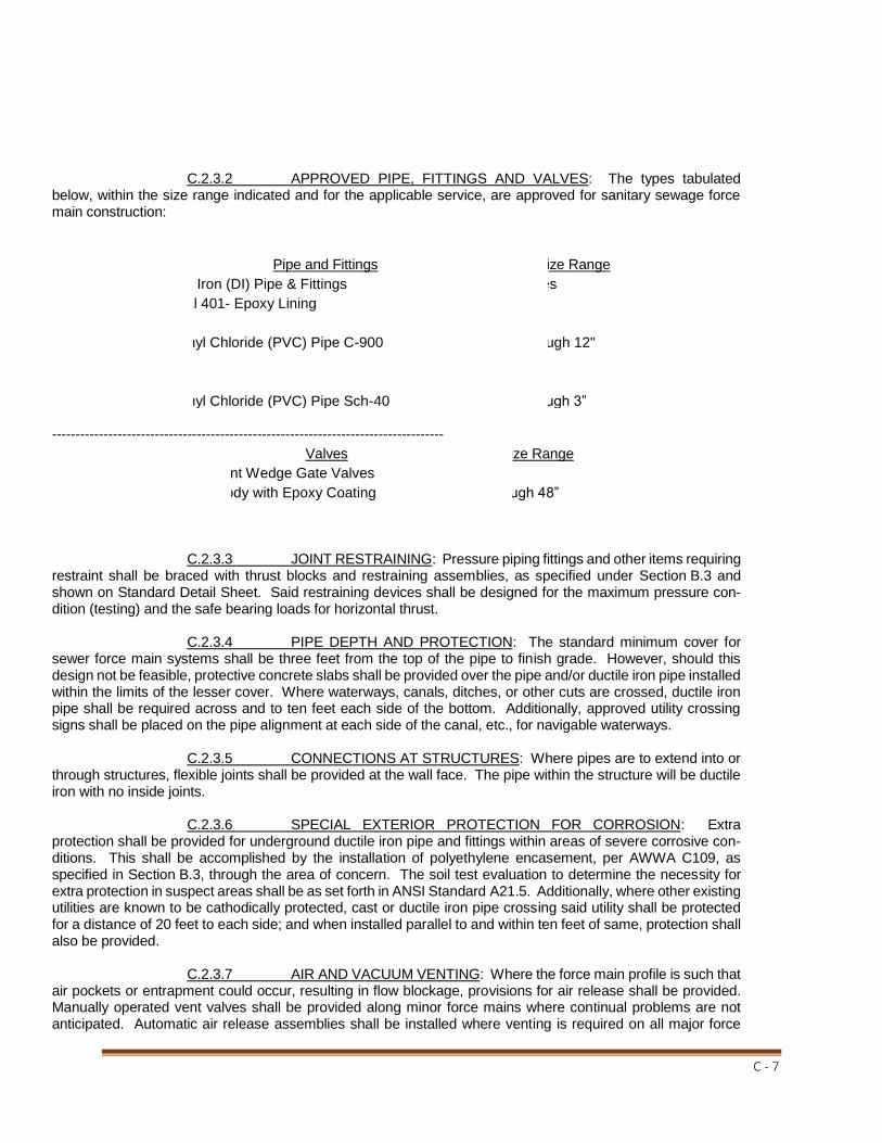
C - 7
C.2.3.2 APPROVED PIPE, FITTINGS AND VALVES: The types tabulated below, within the size range indicated and for the applicable service, are approved for sanitary sewage force main construction:
Pipe and Fittings Size Range
Ductile Iron (DI) Pipe & Fittings All sizes
Internal 401- Epoxy Lining
Polyvinyl Chloride (PVC) Pipe C-900 4" through 12"
DR-18
Polyvinyl Chloride (PVC) Pipe Sch-40 2” through 3” ------------------------------------------------------------------------------------
Valves Size Range
Resilient Wedge Gate Valves
Iron Body with Epoxy Coating 2” through 48” C.2.3.3 JOINT RESTRAINING: Pressure piping fittings and other items requiring restraint shall be braced with thrust blocks and restraining assemblies, as specified under Section B.3 and shown on Standard Detail Sheet. Said restraining devices shall be designed for the maximum pressure con-dition (testing) and the safe bearing loads for horizontal thrust. C.2.3.4 PIPE DEPTH AND PROTECTION: The standard minimum cover for sewer force main systems shall be three feet from the top of the pipe to finish grade. However, should this design not be feasible, protective concrete slabs shall be provided over the pipe and/or ductile iron pipe installed within the limits of the lesser cover. Where waterways, canals, ditches, or other cuts are crossed, ductile iron pipe shall be required across and to ten feet each side of the bottom. Additionally, approved utility crossing signs shall be placed on the pipe alignment at each side of the canal, etc., for navigable waterways. C.2.3.5 CONNECTIONS AT STRUCTURES: Where pipes are to extend into or through structures, flexible joints shall be provided at the wall face. The pipe within the structure will be ductile iron with no inside joints. C.2.3.6 SPECIAL EXTERIOR PROTECTION FOR CORROSION: Extra protection shall be provided for underground ductile iron pipe and fittings within areas of severe corrosive con-ditions. This shall be accomplished by the installation of polyethylene encasement, per AWWA C109, as specified in Section B.3, through the area of concern. The soil test evaluation to determine the necessity for extra protection in suspect areas shall be as set forth in ANSI Standard A21.5. Additionally, where other existing utilities are known to be cathodically protected, cast or ductile iron pipe crossing said utility shall be protected for a distance of 20 feet to each side; and when installed parallel to and within ten feet of same, protection shall also be provided. C.2.3.7 AIR AND VACUUM VENTING: Where the force main profile is such that air pockets or entrapment could occur, resulting in flow blockage, provisions for air release shall be provided. Manually operated vent valves shall be provided along minor force mains where continual problems are not anticipated. Automatic air release assemblies shall be installed where venting is required on all major force

C - 8
mains and at critical points on lesser mains. At profile break points on major force mains, such as tops of hills, etc., where free flow will occur during operation or after pumping stops, combined air release and vacuum valve assemblies may be required. Air and vacuum valves and/or air release valves shall be as specified under Section B.3 and shall be suitably housed in a properly vented underground chamber (manhole). All interior surfaces of the structure and the valves are required to be coated with coal tar epoxy. All Air Release and Vacuum Release valves shall be as manufactured by A.R.I., Inc. Specific Model numbers shall be based on pipe sizes and service operation. C.2.3.8 VALVE LOCATIONS: Valves shall be installed on all subsidiary force mains at the point of connection to the major main in order to isolate said pipeline for maintenance. Where force mains are to be extended, valves shall be placed at the future connection point to preclude line shutdown at the time of extension. At future connection branches or ends, the valves shall not be installed within the run of individual force mains, nor for pipe sizes in excess of 14 inches, without special consideration. Valve locations shall be marked as stated in Section B.3.4.5.2. All valves placed at the end of a line for future connection shall include a blind plug installed on the valve to prevent accidental opening and environmental impact. C.2.3.9 CLEAN-OUT CONNECTIONS: Should force mains appear to be susceptible to sedimentation clogging, as created by depressed crossings or extended low flow (velocity) peri-ods, suitable clean-out connections shall be provided. Clean-outs, such as plugged wye or tee fittings, shall be located to facilitate the subject maintenance operation. This requirement shall be reviewed with the NPRPWD. C.2.3.10 TERMINAL DISCHARGE: Force mains shall enter the terminal facility (gravity sewer manhole, pumping station wet well or other) at a point equal to or below the operational water level of said receiving unit. C.2.3.10.1 DISCHARGE INTO MANHOLES: Force mains entering gravity manholes shall discharge at invert level. A properly formed and directed channel shall be provided to ensure a smooth transition of flow. All manhole receiving discharge from a Force Main shall be internally lined with Spectraguard Lining System. C.2.3.10.2 DISCHARGE INTO PUMPING STATION WET WELLS: Force mains entering wet wells shall be provided with a top vented drop pipe that terminates below the normal operating water level. The drop pipe shall be located to avoid conflicts with pumps, floats, and other equipment and shall be securely fastened to the wet well wall with stainless steel bolts and hardware. C.2.3.11 IDENTIFICATION: All installed underground sanitary sewage force mains shall be marked with a continuous tape located directly above the pipe 12 inches to 18 inches below grade. Said tape shall be a minimum two inches in width and shall be metallic-backed, green, and marked "FORCE MAIN BURIED BELOW". Additionally all installed underground sanitary sewage force mains shall have a Minimum (2) 10 AWG Solid Copper “Green” Continuous Locator Wire installed for the entire length of the pipe run. This Locator Wire shall terminate in locating box station locations or other approved areas as reviewed by the NPRPWD. (See Standard Details – Details 44 & 45.) C.2.4 TESTING: C.2.4.1 The Contractor shall perform hydrostatic testing of all sanitary sewage force mains, as set forth in the following, and shall conduct said tests in the presence of representatives from the Engineer and NPRPWD with two days' advance notice provided. C.2.4.2 Piping and appurtenances to be tested shall be within sections between valves or adequate plugs, with prior approval from the Engineer. Testing shall not proceed until concrete thrust blocks are in place and cured, or other restraining devices installed. All piping shall be thoroughly cleaned and flushed prior to testing to clear the lines of all foreign matter. While the piping is being filled with water, care shall be exercised to permit the escape of air from extremities of the test section, with additional release cocks provided if required.

C - 9
C.2.4.3 Hydrostatic testing shall be performed at 150 psi for two hours. The testing shall continue for an uninterrupted period of not less than two hours. Testing shall be in accordance with the applicable provisions as set forth in Section 4.1 of AWWA Standard C600. The allowable rate of leakage shall be less than the number of gallons per hour determined by the following formula: SD(P) ½ L = ____________ 133,200 L = Allowable leakage in gallons per hour S = Length of pipe tested in feet D = Nominal diameter of the pipe in inches P = Average test pressure maintained during the leakage test in pounds per square inch gauge C.2.4.4 The testing procedure shall include the continued application of the speci-fied pressure to the test system, for the one-hour period, by way of a pump taking supply from a container suitable for measuring water loss. The amount of loss shall be determined by measuring the volume displaced from said container. C.2.4.5 Should the test fail, necessary repairs shall be accomplished by the Contractor and the test repeated until within the established limits. The Contractor shall furnish the necessary labor, water, pumps, gauges, and all other items required to conduct the required sanitary sewage force main testing and shall perform the necessary system repairs required to comply with the specified hydrostatic test.
SECTION C.3 LIFT STATIONS, PUMPS, AND CONTROLS
C.3.1 GENERAL: C.3.1.1 The work included under this section consists of the furnishing and installing of pumps, controls and related equipment for Pump Stations as specified herein and as shown on the drawings. ALL METEL COMPONENTS IN THE WETWELL, WITH THE EXCEPTION OF THE PUMPS, MOTORS AND STATION PIPING SHALL BE ALUMINUM OR STAINLESS STEEL. THE PUMPS, MOTORS, CONTROL PANEL, FRAME AND COVER, SHALL BE SUPPLIED BY THE PUMP SUPPLIER TO INSURE UNIT RESPONSIBILITY. The contractor shall furnish and install two totally submersible sewage pumps as manufactured by Flygt or approved equal, conforming to size, voltage, phase and pumping capability determined on an individual basis. C.3.1.2 This section includes the general requirements for the design criteria and installation of lift stations, pumps, and controls. C.3.1.3 The relevant provisions included in Division B, “Technical Requirements – General”, Section C.1 – “Sanitary Gravity Sewers”, Section C.2 – “Sanitary Sewage Force Mains”, and shown on the attached “Standard Detail Sheet” shall be applicable to this section, unless otherwise indicated herein or approved by the Director. C.1.3.4 On projects where the NPRPWD is the owner, pumps, appurtenances, and controls will be supplied by the same supplier. C.3.2 DESIGN STANDARDS:

C - 10
C.3.2.1 REQUIRED REFERENCE: The plans shall comply with the applicable regulations established by the Florida Department of Environmental Regulation. Additionally, the criteria provided in Chapter 30 - “Sewage Pumping Stations”, of the Ten State Standards – “Recommended Standards for Sewage Works” may generally be utilized as design guidelines, if not in conflict with State, City, or other regulatory agency requirements. C.3.2.2 DESIGN FLOWS: Sewage pumping stations shall be designed for the total ultimate development flow from all contributory areas. Said contributions shall include the immediate gravity system, subsidiary sources, and known or projected future development within the designated station service area. The design of average daily flow shall be computed at the unit rates set forth under Paragraph C.1.2.2.1, Section C.1 – “Sanitary Gravity Sewers”. The maximum required pumping capability shall be the product of selected peak factors times the Maximum Monthly Average Daily Flow (MMADF) from the total service area. In general, the following factors shall be applicable for the range of flow contributions indicated (million gallons per day – average daily flow: MGD-ADF), unless larger values are required or smaller amounts are justified, with prior approval from the Department.
Flow Range (MMADF) Peak Factor
-- to 0.100 mgd 3.8
0.101 to 0.250 mgd 3.5
0.251 to 1.000 mgd 3.0
1.001 to 4.000 mgd 2.4 C.3.2.3 PUMP SELECTION: C.3.2.3.1 Pumping stations shall have a minimum of two pumps per unit. Where the peak design flow exceeds 1,000 GPM, three or more units may be required in the facility. In all cases, standby pumping capability shall be provided, such that if any one pump is out of service, an alternate pump is available at equal or greater capacity. Pumps shall be manufactured by Flygt Company or approved equal with a minimum of a five-year warranty on major parts. Pumps shall be submersible type. C.3.2.3.2 The selected sewage pump system shall have the minimum capability of pumping the design peak flow at the maximum computed system Total Dynamic Head (TDH) requirements. Additionally, final selection shall be coordinated with force main systems sizing as described under Paragraph C.2.2.3, Section C.2 – “Operational Costs Considerations,” C.3.2.3.3 Head-capacity curves shall be prepared for the proposed pumping system in order to determine the various operational conditions. Hydraulic computations shall be in accordance with good engineering practice, with pipe friction loss calculated by the “Hazen-Williams Formula”, using standard frict6ion factors based on the material utilized; however, not greater than “C = 140”, unless the justification for higher values is authorized by the Engineer. The system head capacity analysis shall provide the following and be subject to review by the NPRPWD: a) System operation under peak flow conditions, with one pump or multiple parallel pumping, as designed. Should the receiving force main system be interconnected to additional pumping stations, hydraulic design conditions shall also include said pumping systems operating at rated capacity. b) Pumping capability with one pump running, all units operating in parallel and other combinations, if applicable. c) For multiple pumping station force main systems, the one pump maximum capacity under minimum flow contribution conditions from the other connected facilities shall be calculated. C.3.2.4 WET WELL DESIGN: The wet well structure shall
C - 11
provide a capacity, between operational water levels, sufficient to allow a minimum of five minutes between successive starts of the pumps, under the following condition: Influent rate of one-half the maximum one pump capacity (Paragraph C.3.2.3.3(c), if applicable); and one pump running at said maximum. Additionally, wet wells shall provide sufficient space for installed equipment, required suction pipe submergence and spacing, and shall not be less than six feet in minimum horizontal dimension or provide less than 24 inches between shutoff (low water) and lead pump start levels. Low water level shall be set to allow pumps to remain completely submerged at shut-off. In general, the normal operational water level shall provide a positive suction head for the sewage pumps. Operational maximum or high water levels shall not exceed the invert elevation of the lower influent pipe, with high water alarm no higher than the 0.8 point of said pipe. A minimum size hopper bottom shall be provided, with the wet well floor sloping to said bottom at a slope of not less than one to one (1:1). Interior of Wet Well and piping will be coated with Spectrashield by Concrete Conservation, Inc. (6525 Greenland Road, Jacksonville, FL 32241-4354). C.3.3 GENERAL REQUIREMENTS: C.3.3.1 SITE: Pumping stations shall be installed on readily accessible sites not requiring trespassing through or onto private property to gain access and must be approved by the NPRPWD. Sites shall have adequate area provided for operation and maintenance of the facility and shall be well drained and not subject to flooding. Site fencing shall be provided when specifically requested by NPRPWD. C.3.3.2 STRUCTURES: Where buildings and/or structures are constructed, the relevant provisions of the City of New Port Richey Building Codes shall apply with special design considerations for the following, where applicable. All State and Federal safety codes shall be complied with. C.3.3.2.1 Pumping stations structures shall be of adequate size to allow easy access to all operating equipment for service and maintenance. C.3.3.2.2 Structural openings shall be provided through walls or roofs to facilitate equipment removal, including pumps and motors, standby generators, communitors or bar screens, and other large items. C.3.3.2.3 Structural provisions shall be made for future pumping station expansion, if anticipated or planned. C.3.3.2.4 Should hoisting equipment be scheduled for initial or future installation, adequate ceiling height and structural considerations shall be provided. C.3.3.3 HOISTING EQUIPMENT: Where required in large installations, in order to assist in maintenance operations, hoisting equipment shall be provided to lift pumps, motors, chlorine cylinders, and other heavy equipment. Hoists shall be sized to accommodate the load for which provided and may be hand operated to a capacity of two tons. Those units above two-ton capacity and where one-ton chlorine cylinders are to be lifted shall be motor-driven. Hoists shall be trolley-mounted from a continuous beam over chlorine cylinder storage and operation areas, and at all other locations insofar as possible, to allow lateral movement of the hoisted item. Where hoisting equipment cannot be permanently installed or at minor equipment items, hoist eyes shall be installed over the unit. C.3.3.4 PIPING SYSTEM FOR LIFT STATIONS: C.3.3.4.1 APPROVED PIPE, FITTINGS AND VALVES: The following material or item shall be suitable for the indicated operational service: a) Gravity Sewer Influent Pipe and Fittings (within the limits of the site) – Ductile iron (no size limit), with interior 401 epoxy coating. b) Sewage Pressure Pipe and Fittings – Ductile iron (four inch minimum), with interior lining.

C - 12
c) Sewage Service Valves – Gate valves (resilient wedge), with non-rising stems and operating nuts suitable for underground service with flanged end connections. d) Potable or Non-potable Water – Galvanized steel or polyvinyl chloride pipe and fittings, with appropriate gate valves (see Section B.3). e) Chlorine Solution – Schedule 80 polyvinyl chloride pipe and fittings with PVC ball valves for control. f) Fuel oil or Gas – Black steel pipe and fittings with exterior protection for underground installation (see Section B.3). C.3.3.4.2 CONNECTIONS AT STRUCTURES: Where cast or ductile iron pipes are to extend into or through structures from the exterior, flexible connections (mechanical or push-on type joints) shall be provided at the exterior wall face. C.3.3.4.3 WALL PIPES OR SLEEVES: For pipes passing through structural walls, “Link-Seal” or equal shall be installed. C.3.3.4.4 PIPING FLEXIBILITIY: In order to provide for expansion and contraction or expedite installation and maintenance, flexible connections (flanged coupling adapters, expansion joints, couplings, etc.) may be required within flanged piping systems. C.3.3.4.5 SUPPORTS AND RESTRAINING: Special consideration shall be given to the support and restraining for piping systems (see Section B.7). This requirement shall apply to both interior and exterior systems, with restraining of flanged pressure piping required where flexible connections are used. C.3.3.5 STATION WATER SYSTEM: All sewage pumping stations shall be proved with a station water system with adequate capacity and pressure, for wash down or pump seal water. Hose bibs shall be provided as specified to facilitate maintenance, with special large capacity units installed for wet well wash down and hose provided therefore. Water system shall have a hose-bib vacuum breaker. Minimum size wash-down water supply line shall be one inch. Backflow prevention shall be provided which is compliant with City Requirements: A lift station is considered a “high hazard” area, thus requiring reduced pressure zone assembly (RPZ). Reduced Pressure Zone assemblies in commercial installation will be tested annually by the City of New Port Richey. The tests will be performed by certified backflow prevention technicians in accordance with procedures and guidelines established by the University of Southern California Foundation for Cross Connection Control and Hydraulic Research. C.3.3.6 PRESSURE GAUGES AND GAUGE CONNECTIONS: Gauge connections shall be provided on each sewage pump discharge pipe, inside the valve vault ahead of the check valve. One gauge will be required per lift station. The gauge shall read in pounds per square inch, with a range suitable for the required service, and shall be four-inch dial, stainless steel case, “Duragauge”, as manufactured by Ashcroft, of approved equal. Gauges shall be equipped with diaphragms (neoprene or stainless steel), or other separating device, to preclude sewage from entering the mechanism. C.3.3.7 EMERGENCY PUMP CONNECTIONS: Connections shall be provided for emergency auxiliary pumping. The connection device will normally be a three-inch “Cam-Loc”; however, a larger size may be specified by the NPRPWD, if necessary. C.3.3.8 SEWAGE PUMPS AND MOTORS: C.3.3.8.1 GENERAL: Sewage pumping units shall be capable of handling raw, unscreened sewage and shall be capable of passing a sphere of at least three-inches in diameter. The pumps shall be easily removable for inspection or service, requiring no bolts, nuts or other fastenings to be removed and no need for personnel to enter the pump well. Each pump shall be fitted with a
C - 13
stainless steel wire rope and “grip eye” of adequate strength and length to permit raising the pump for inspection. Pumps shall be electric motor driven and of a proven design that has been in sewage service under similar conditions for at least five years. Pumps shall provide the required peak design performance requirements and be suitable for operation within the total hydraulic range of operation. C.3.3.8.2 PUMP CONSTRUCTION: The stator casing, oil casing and impeller shall be of grey iron construction, with all parts coming into contact with sewage protected by a coat of rubber-asphalt paint. All external bolts and nuts shall be of stainless steel. A replaceable wear ring designed for abrasion resistance shall be installed at the inlet of the pump to provide protection against wear to the impeller. The impeller shall be of a non-clog design, capable of passing solids, fibrous material, and heavy sludge and constructed with a long thruway with no acute turns. Each pump shall be provided with a tandem double mechanical seal running in an oil reservoir, composed of two separate lapped face seals. The lower consisting of one stationary and one positively driven rotating tungsten-carbide ring, with each pair held in contact by a separate spring. The seals shall require neither maintenance nor adjustment, and shall be easily replaceable. Conventional double mechanical seals with a single or double spring between the rotating faces, requiring constant differential pressure to effect sealing and subject to opening and penetration by pumping forces shall not be considered equal to the tandem seal specified. C.3.3.8.3: A sliding guide bracket shall be an integral part of the pumping unit and pump casing shall have a machined connecting flange to connect with the cast iron discharge connection, which shall be bolted to the floor of the sump and so designed as to receive the pump connecting flange without the need of any bolts or nuts. C.3.3.8.4: Sealing of the pumping unit to the discharge connection shall be accomplished by a simple linear downward motion of the pump with the entire weight of the pumping unit guided by no less than two guide ears to and pressing tightly against the discharge connection; no portion of the pump shall bear directly on the floor of the sump and no rotary motion of the pump shall be required for sealing. Sealing at the discharge connection by means of a diaphragm, O-ring, or similar method of sealing will not be accepted as an equal to a metal contact of the pump discharge and mating discharge connection specified. C.3.3.8.5: Pump motor shall be housed in an air-filled watertight casing and shall have Class F insulated stator windings which shall be heat shrink fitted into the stator housing. The use of bolts, pins or other fastening devices requiring penetration of the stator housing shall not be acceptable. The motor shall be Nema Design, B rated, 155 degrees C to permit continuous operation, in a totally, partially, or non-submerged condition. The pump shall be capable of running dry continuously in a totally dry condition. Before final acceptance, a field running test demonstrating this ability, with twenty-four (24) hours of continuous operation under the above conditions, shall be performed for all pumps being supplied, if required. Cable junction box and motor shall be separated by a stator-lead sealing gland or terminal board which shall isolate motor from any water or solids gaining access through pump cable. Pump motor cable shall be suitable for submersible pump applications and shall be permanently embossed on the cable. C.3.3.8.6 PUMP TEST: The pump manufacturer shall perform the following tests on each pump before shipment from the factory: 1. Megger the pump for insulation breaks or moisture. 2. Prior to submergence the pump shall be run dry and checked for correct rotation. 3. Pump shall be run thirty (30) minutes in a submerged condition. 4. Pump shall be removed from test tank, meggered immediately for moisture; oil plugs removed for checking of upper seal and possible water intrusion of stator housing. 5. A written certified test report giving the above information shall be supplied with each pump at the time of shipment when required.

C - 14
C.3.3.8.7 PUMP WARRANTEE: The pump manufacturer shall warrant the pumps being supplied to the owner against defects in workmanship and materials for use, operation and service. The manufacturer shall submit the published warranty with the submittal drawings. C.3.3.8.8 FACTORY SERVICE: Authorized factory approved service facilities and factory trained mechanics shall be available within 120 miles of the project location. C.3.3.8.9 EXPERIENCE CLAUSE: The pump manufacturer shall have a minimum of 10,000 similar units installed and operating for not less than five (5) years in the State of Florida. C.3.3.9 TELEMETERING SYSTEM: All sewage pumping stations shall be equipped for and connected with the New Port Richey Telemetry (SCADA) System. The necessity for telemetering, whether immediate connection is to be accomplished or controls provided for future accommodation shall be reviewed with the Director. Should said installation be required, the system shall be compatible with the existing City facility. As Manufactured by Digital Controls Corporation, 10871 75th Street North, Largo, Florida 33777, 1—800-335-5219 or 1-727-547-1622. C.3.3.10 EMERGENCY GENERATORS: Standby emergency generators may be required at Type III sewage pumping stations which are at critical points in the sewer system. Pumping stations designed for a present capacity of 1,000 GPM or more should be discussed with the NPRPWD about the possibility of requiring such a system. Said installation shall be a diesel engine generator of adequate size to automatically start and operate the pump(s) required for design flow conditions, lights, controls, and other critical items. The engine generator installation shall be in accordance with all applicable codes and the manufacture’s recommendations. The facility shall be as manufactured by Caterpillar, Onan, Kohler, or approved equal. C.3.4 LIFT STATION CONSTRUCTION: C.3.4.1 Lift stations are divided into three categories as follows: Type I: Duplex Station: Two-pump station up to 14 hp range, three-phase, 110/230V equipment. Wet well is sized six feet in diameter minimum. Type II: Modified Duplex Station: Two-pump station, 10-47 hp range, three-phase, 230V equipment. Wet well is sized eight feet to ten feet in diameter. Type III: Triplex Station: Three-pump station, 20 hp and greater, three-phase, 230V equipment. Wet well is greater than ten feet in diameter and sized as required by the Engineer. These specifications are not intended to dictate design requirements for triplex stations. Type III stations are designed for future upgrade and require pipe and valve sizing for the maximum anticipated loads. C.3.4.2 ACCESS FRAME AND GUIDES: The aluminum access frames and covers are to be manufactured with ¼” thick one-piece aluminum extruded frame, having a continuous concrete anchor as part of the one-piece extrusion. Door panels are ¼” thick aluminum diamond plate, capable of withstanding a live load of 150 p.s.f., with a safety factor of 3x. The doors shall have stainless steel hinges with tamper-proof fasteners. All hardware shall be stainless steel. Doors will open to a full 90 degrees and will be locked automatically in that position by a stainless steel positive locking arm and release handle. Doors will close flush with the top of the frame and rest on a ½” wide lip, for added support, around the inside perimeter of the frame. C.3.4.3 VALVE VAULT: Sizing of the access frames and covers will be as per plans and/or recommendations of the pump and valve suppliers. Covers shall be of adequate size to permit servicing of equipment through them. The interior of the valve vault shall be coated with Spectrashield by Concrete Conservation, Inc. (6525 Greenland Road, Jacksonville, Florida 32241-4354).
C - 15
C.3.4.4 GRIP-EYE: In lieu of the lifting cable, the pump manufacturer shall furnish a special, cast GRIP-EYE and a 12” long stainless steel chain permanently attached to the pump bail. A separate stainless steel “fish” cable shall also be furnished to positively allow the GRIP-EYE to engage the lifting chain and raise the pump. C.3.4.5 SWING CHECK VALVE: M & H Weighted or spring type lever of the type and size called for in the plans and specifications shall be furnished and installed. The design of the valve shall be such that it keeps solids, stringy material, grit, rags, etc. moving. The Clapper shall clear the water way providing “full flow” equal to the nominal size. The Clapper shall be resistant to grease, petroleum product, animal and vegetable fats, diluted concentration of acids and alkaline (pH 4-10), tearing and abrasion. The body and cover shall be of grey cast iron, Class 35. Flange drilling shall be according to ANSI B-16.1. class 125. C.3.5 RESPONSIBILITIES: C.3.5.1: All work shall be in accordance with these Design Standards and Specifications. C.3.5.2: The Engineer shall be responsible for coordinating of all design with the NPRPWD. C.3.5.3: The NPRPWD shall approve all designs and determine the requirements for future upgrading of all lift stations. Lift stations requiring upgrading shall be designed and constructed to meet the anticipated flows of the development. C.3.5.4: An overall layout of the entire development, including phasing, shall be required. Lift stations shall be designed for the ultimate build-out. Lift stations shall require an easement and access road as follows unless otherwise approved by NPRPWD: Easement of right-of-way with a crowned roadway with adequate drainage. Roadway shall be ten feet wide with eight inches of lime rock with compaction equal to 98 percent maximum density as determined by AASHTO Specification T-99. The roadway shall have a smooth finish of one inch minimum asphaltic concrete and provide unobstructed access to the wet well. Site shall be secured with a six-foot chain link fence (see Standard Details – Detail 3 “Fence Specifications) when specifically requested by NPRPWD. C.3.6 CONTROL PANEL C.3.6.1 GENERAL REQUIREMENTS: It is the intention that this specification shall cover a complete Electrical Lift Station Pump Control System as hereinafter described, and all necessary appurtenances which might normally be considered a part of the complete electrical system for this installation. All of the automatic control equipment is to be supplied by one manufacturer. It shall be factory assembled, wired and tested, and covered by complete electrical drawings and instructions. Control, alternation, logic function, alarm and all other control components used in the control system shall be performed by solid-state components which shall be standard catalog items of the system manufacturer, with proven field performance. At least one module of each type used in the system shall be stocked by the system manufacturer for system expansion or renewal parts purposes. The modules shall be of a compatible, integrated control family with a full range of control/protective/alternation/telemetry capabilities and associated housings, enclosure system and appurtenances to perform a variety of functions as required by this specification to disallow non-standard, “one of a kind”, experimental, unproven combinations of equipment. All equipment shall be guaranteed against defects in material and workmanship for a period of one year from date of Owner’s final inspection and acceptance to the effect that any defective equipment shall be repaired or replaced without cost of obligation to the Owner. C.3.6.2: The pump control panel shall be furnished by the pump supplier and installed in a location as shown on the plans to operate (2) Flygt submersible pumps of the HP and voltage as designated by the City. C.3.6.3: The control function will provide for the operation of the lead pump under normal conditions.

C - 16
If the incoming flow exceeds the pumping capacity of the lead pump, the lag pump will automatically start to handle this increased flow. As the flow decreases, pumps will be shut off at the elevation shown on the plans. In the event of a malfunction or a flow that exceeds the capacity of the pumps, a high or low level audible alarm and light will be excited to indicate the alarm conditions. A reset function shall lock out the audible alarm; however, the alarm light shall release only with the correction of the high level condition. C.3.6.4: The control panel shall conform to all requirements necessary to operate two Flygt submersible pumps. Submittal drawings, electrical data and schematics, will be submitted to the NPRPWD for approval prior to fabrication of this panel to insure that the pumps will operate properly. C.3.6.5 ELAPSED TIME METERS: The panel shall include a non-resetable type elapsed time meter for each starter mounted on the inner door to record the accumulated running time of each pump. C.3.6.6 CONVENIENCE RECEPTABLE: The panel shall have a GFI receptacle mounted on the inner door to provide plug-in with 120V power with ground protection. This receptacle shall be protected by a separate 30 ampere trip rated circuit breaker. C.3.7 ELECTRICAL CONTROLS C.3.7.1 INTENT OF SPECIFICATION: The Contractor shall furnish and install a pump control panel designed to automatically operate the pumps as described herein. The pumps will operate in a specified sequence, in response to variations in the liquid level. C.3.7.2 WIRING: All wiring shall have not less than 600 volt insulation and all power wiring and bus shall be in complete conformity with the National Electrical Code. All Control Wiring shall be as manufactured by Spectro Wire & Cable PN – UL1015-16/26 “Tin Plated”. Control wiring shall be color coded. All job connections required to conveniently replace control components shall be made at approved type terminal blocks with marker strips or similar approved means. C.3.7.3 ENCLOSURE: The described equipment shall be housed in a type 4X stainless steel enclosure arranged for integral pole or pedestal mounting where shown on the drawings. Minimum size will be 36”W x 48”H x 12”D. This weatherproof, tamper-proof, rain tight enclosure shall be designed specifically for mounting in an unprotected outdoor location. It shall have a gasketed, continuously hinged, front weather door with locking capability, and an adjustable 140 stainless steel hold-open arm. It shall have an internally mounted (aluminum) hinged dead front panel so that the components normally actuated by operating personnel are accessible without opening the dead front and yet are not exposed to the elements or to unauthorized personnel. All major components and sub-assemblies shall be identified as to function with laminated, engraved bakelite nameplates, or similar approved means. The following described equipment shall be furnished in each panel and matched to the specific pumping station equipment: C.3.7.3.1: The control panel shall have two integral mechanically interlocked Square D FAL Frame magnetic circuit breakers, with a minimum amperage interrupting capacity of 10,000, 240V symmetrical RMS amps to transfer power from normal to emergency service. The circuit breakers shall be sized per NEC requirements for this specific application. A single rotary disconnect transfer switch is not acceptable. Generator receptacle shall be an Arktite Model AR2042 supplied as needed and called for by specification. It shall be weatherproof and mounted on the side of the enclosure be the panel manufacturer. C.3.7.3.2: A Square D FAL Frame industrial type circuit breaker shall be supplied as branch circuit protection for each pump motor. The circuit breaker must have a minimum ampere interrupting capacity of 10,000 240V symmetrical RMS amps. C.3.7.3.3: A NEMA rated full-voltage across the line magnetic motor starter with ambient-compensated, quick-trip class 20 NEMA overload sensing in each phase motor. Overload protection shall be provided by accurately sized replaceable heater elements.

C - 17
C.3.7.3.4: A 1-7/32” diameter “hand/off/auto” three (3) position, rotary, oil tight, heavy duty type selector switch shall be furnished for each pump. C.3.7.3.5: An inner door mounted pilot LED, operated from a respective starter auxiliary contact, shall be provided to indicate a “pump running” condition. The pilot LED shall be a LED type with replaceable bulb. C.3.7.3.6: A control panel circuit breaker shall be provided and operable throughout the inner door of the control panel to provide a disconnect means and short circuit protection for any 120 VAC control power transformer (750 VA standard) shall be provided where required. C.3.7.3.7: A running time meter, measuring hours and tenths of hours of operation up to 99999.9 hours shall be furnished for each pump motor indicated. This shall be a 120 volt AC device operating from the control voltage by an auxiliary contact of the motor starter and shall show operation by means of a visible, rotating element. C.3.7.3.8 PHASE MONITOR: A phase loss/imbalance/reversal, under-voltage protection assembly shall be furnished with adjustable nominal voltage setting and three line voltage fuses. This device shall drop-out pumps if all phases drop below 90% or if one phase drops below 80-83% nominal voltage, or upon phase reversal. This devise shall have a 5-second drop-out delay. C.3.7.3.9 LIGHTING ARRESTOR: A lightning arrestor shall be supplied on the exterior of the control panel and connected to each line of the incoming side of the power input terminals. The arrestor shall protect the controls against damage due to lightning strikes on the incoming power line. C.3.8 LEVEL-RESPONSIVE AUTOMATIC PUMP AND ALARM CONTROL C.3.8.1: An automatic pump control system shall operate the pumps in accordance with variation in the wet well liquid level. The automatic control system shall employ a solid-state bubbler system to sense the liquid level. The automatic control system shall be a bubbler type level sensor and pump controller system designed for lift station use. It shall be calibrated for a 0 to 10 foot operating range. For duplex stations the controller shall be a Digital Control 11928-3 or 11928-4 or approved equal. For triplex stations the controller shall be a Digital Control 11967-3 or 11967-4 or approved equal. C.3.8.2 LIQUID LEVEL PUMP CONTROLLER: The system shall sense the station wet well sewage level over a calibrated range; display it on a 4-inch LED bar graph on the face of the controller, provide for display and setup of all controller set points, and provide automatic operation of the station pumps and alarms as hereinafter or otherwise described. The control system shall be completely functional and include not less than the following features: o Controller with air system to be an integrated standard product of an experienced manufacturer o 0 to 10’ wet well level range o 40 segment LED bar graph level display o Independent on and off set points for each pump o Solid-state automatic pump alternation o High and low level alarms o Front panel test capability o Integrated bubbler system with automatic and timed purging o Float backup capability o Time delay between pump starts o One year factory warranty on parts and labor C.3.8.3 MAIN POWER DISCONNECT: Shall include a knife switch sized as required for

C - 18
disconnecting main power to panel box and will be housed in a separate enclosure mounted behind the main panel box an indicated on the detail drawing. This disconnect enclosure shall be of a stainless steel weatherproof construction. Where required by the power company, an additional disconnect will be provided prior to the meter. C.3.8.4 ELECTRICAL JUNCTION BOX: A junction box (12” x 12” x 6” minimum) with stainless steel non-corroding, heavy-duty type terminal strips shall be installed below the panel box. The junction box will be of 304 stainless steel construction with weatherproof cover and fittings. Three explosion-proof vapor seals will be installed between panel box and junction box for the float circuits, motor No. 1, and motor No.2. Three removable vapor seals shall be installed between the junction box and the wet well. Separate conduits will be provided between the wet well and the junction box for the float switch conductors, pump No. 1 conductors, and pump No. 2 conductors. C.3.8.5 LOCAL ALARM SYSTEM: A weatherproof, high/low water, flashing alarm light assembly, including a high impact resistance lexan red lens shall be included. The alarm light bulb shall be replaceable from inside the control panel without having to remove the weatherproof red lens from the panel. A weatherproof externally mounted electronic 12VDC alarm horn with alarm silence circuit mounted internally & externally shall also be provided. Note: All electrical components to be Square “D” or approved equivalent. C.3.9 MANUFACTURER’S SHOP DRAWING C.3.9.1: The Developer’s Engineer shall provide, along with the preliminary drawings, engineering data clearly marked with the name of the project, equipment, and fabricated materials to be furnished by the Manufacturer to the City. Note: Three sets of shop drawings will be provided. C.3.9.2: Shop drawings will include information on pumps, guide rails, control panel, electrical schematics, access doors, and any other requirements necessary to complete the lift station installation. C.3.9.3: Data shall include drawings and descriptive information in sufficient detail to show the kind, size, arrangement, and operation of component materials and devices; the external connections, anchorages, and support required; and dimensions needed for installation and correlation with other materials and equipment. All part numbers and catalog data required for ordering spares and replacements shall be provided. C.3.9.4: The NPRPWD’s approval of drawings returned marked “APPROVED” or “APPROVED AS NOTED” will not constitute a blanket approval of all other dimensions, quantities, and details of the materials, equipment, device, or item shown and does not relieve any responsibility for errors or deviations from the requirements. C.3.9.5: The submitted drawings and data shall be published by the manufacturer and shall include, but not be limited to, the following: a) Mechanical Equipment 1) Assembly drawings, nomenclature, and materials list. 2) Outline dimensions and weights. 3) Drawings, method of anchoring equipment, and piping connection details sufficient to permit design of supportive structures and connections. b) Electric Motors 1) Name of Manufacturer.

C - 19
2) Type, model, and frame size. 3) Motor horsepower. 4) Full load speed. 5) Construction. 6) Temperature rise and class of insulation. 7) Service factor. 8) Voltage, frequency, number of phases. 9) Full load current. 10) Locked rotor current. 11) Motor efficiencies at ½, ¾, and full load. c) Controls and Wiring Diagram 1) Wiring diagram of all electrical and control components. 2) Assembly drawings, nomenclature, and materials list. 3) Outline and dimensions and heights. 4) Method of anchoring control panels, and electrical connection details sufficient to permit design of supportive structures and connections. 5) Detail description of components. C.3.9.6: Each pump shall be tested in the Manufacturer’s shop to demonstrate the proper operation of all components. The testing shall determine overheating of bearings, motors, or other components. C.3.10 WARRANTY C.3.10.1: In order to ensure the proper performance and compatibility of interacting components within the intent of these specifications, the pumps, control center, access frame, and associated appurtenances shall be warranted by the same supplier. C.3.10.2: The pump manufacturer shall warrant the pumps and accessories being supplied to the City against defects in workmanship and materials for a minimum of one year under normal use, operation, and service. In addition, the manufacturer shall replace certain parts which shall become defective through normal use and wear on a progressive schedule of cost for a period of five years; parts included are the mechanical schedule of cost for a period of five years; parts included are the mechanical seal, impeller, pump housing, wear ring, and ball bearings. The warranty shall be in published form from the manufacturer and apply to all similar units. C.3.11 EVALUATION OF MATERIALS C.3.11.1: The evaluation of the shop drawings shall be on the basis of conformance to these specifications. C.3.11.2: The evaluation shall be based on Manufacturer’s data submitted and shall include the

C - 20
following considerations: a) Equipment and materials to be provided. b) Owner’s requirement for inventory of spare parts. c) Project design changes which would be required to accommodate proposed equipment and materials. d) Maintenance and frequency of inspection to ensure reliability and performance of the equipment. e) Experience and performance record of the Manufacturer, and/or the Manufacturer’s local representative, work of comparable size and availability of qualified field service personnel. f) Manufacturer’s service facilities, experience, and availability of qualified field service personnel. C.3.12 INSPECTION Inspection shall be coordinated with the NPRPWD. The inspection shall be conducted in two phases as follows. Phase I: Mechanical phase, including piping, receiving manhole, wet well, and valve pit shall be performed by the NPRPWD. Phase II: Electrical phase, including control panel, pumps, and distribution system shall be performed jointly between the NPRPWD, and the City of New Port Richey Building Inspections Division. Note: General Contractor shall require the services of a licensed Electrical Contractor during the electrical construction phase of the lift station. Contractor will be responsible for removing pumps from wet well for inspection. C.3.13 START-UP/FINAL ACCEPTANCE C.3.13.1: The NPRPWD shall be notified 48-hours prior to start-up of the lift station. During start-up, the Manufacturer’s representative shall be present at the job site. The Manufacturer’s representative shall be responsible for delivery of the following: a) Three Parts Manuals in paper and digital format. b) Three Pump O/M Manuals in paper and digital format. c) Three complete sets of schematics and Final As-Built on paper and digital images, JPEG compressed and/or CAD. d) Five sets fuses/bulbs. C.3.13.2: The NPRPWD inspectors will adhere to the following lift station check list. The Contractor shall be responsible for, but not limited to, the following: a) Alignment of lift station, access road, control panel, and fencing shall be constructed as indicated on the plot plan. Control panel doors must open such that the Operator does not have his back to the wet well. Unobstructed access must be provided to wet well. b) The 90-degree bends located at top of the discharge line shall not be installed into the grout. c) The ends of stainless steel guide rails shall have the threaded ends cut off. All guide rails shall be attached to access lid frame with approved bracket assemblies. Intermediate guide rail supports shall be

C - 21
provided per Manufacturer’s recommendations. Guide rails shall be Schedule 40 Stainless Steel piping. d) Wet well and valve pit lifting eyes shall be removed below surface and grouted flush after installation to avoid any tripping hazards. e) Concrete work to be of professional quality with nonskid broom finish. f) A two-inch PVC drain pipe shall be installed between wet well and valve vault. A “P” trap shall be installed on the drain pipe within the wet well. g) Force main check valves shall be installed in the proper flow direction. Shut-off valves must be resilient wedge gate valves. h) All discharge elbows shall be level and plumb to ensure all guide rails will work properly and pumps seat properly and can be removed easily. i) All adapter flanges shall be installed according to drawings to allow easy removal of valves. Torque all bolts according to the Manufacturer’s recommendations. j) All conduit and fittings for conductors between the junction box and the wet well shall be two-inch (minimum) PVC pipe, Schedule 40, unless otherwise noted. k) All electrical component penetrations of the panel box shall be properly sealed to prevent water intrusion. l) Water service shall be installed on the panel box mounting post with galvanized retaining straps. Components shall include a lock-wing ball valve, hose bib, and RPZ devise as specified in Section D.2.8.3. C.3.13.3: Upon completion of the work and prior to the release of any assurances of completion or performance bond, contact the NPRPWD for information on requirements for the preparation of assurances of maintenance for water and wastewater utility systems.

DIVISION D
POTABLE WATER FACILITIES

D - 1
DIVISION D
POTABLE WATER FACILITIES
SECTION D.1
WATER DISTRIBUTION SYSTEMS D.1.1 GENERAL: D.1.1.1: This section sets forth the general requirements for design and installa-tion of water distribution systems for potable service. D.1.1.2: The relevant provisions specified in Division B, "Technical Re-quirements", shall be applicable to this section unless otherwise indicated herein or changed in writing by the Director. D.1.2 DESIGN STANDARDS: D.1.2.1 REQUIRED REFERENCE: The plans shall comply with the design and installation requirements as specified by the "Ten States Standards for Water Works", unless otherwise indicated herein or approved by the Public Works Department. D.1.2.2 SYSTEM DESIGN: D.1.2.2.1 NORMAL FLOW DEMANDS: Flow demands for design shall be calculated on the basis of full ultimate development as known, or projected. The average daily flow for domestic use shall be calculated at the minimum rate of 215 gallons per day per single-family residence. Maximum-day demand to be used for design shall be computed by using peak factors of 1.67 for individual customers and 1.25 for bulk service customers. Flow demands for commercial, industrial, or other special developments shall be established from existing records or by estimated projections, using the best available data. D.1.2.2.2 SYSTEM SIZE COMPUTATION: The minimum design for water distribution systems shall provide for at least 100 percent of the combined maximum-day demand rate and required fire flow for said rate, with special provisions for peak flows in excess thereof. The allowable minimum service pressure under said design condition shall not be less than 20 psi. Design computation shall be by the "Hardy Cross" procedure for developments larger than 250 units, or other applicable methods, as dictated by the system configuration. Design flows and method of computation shall be subject to review and approval by the Engineer. D.1.2.2.3 VALVE LOCATIONS: Valves shall be provided for all branch connections, loop ends, fire hydrant stubs, or other locations, as required to provide an operable, easily main-tained and repaired water distribution system. Valves are to be placed so that the maximum allowable length of water main required to be shut down for repair work shall be 500 feet in commercial, industrial, or high density residential districts, or 1,000 feet in other areas. Water mains ending as stub-outs, intended for future expansion, shall terminate with a line size gate valve and temporary blow-off, so designed that water service is not interrupted during tie-in. Valve locations shall be marked as specified in Section B.3.4.5.2. A two by four wooden stake, painted blue, shall temporarily mark valve boxes during construction. Hydrant valves shall be installed as not to exceed six (6) feet from the center of the fire hydrant. D.1.2.2.4 PIPELINE HORIZONTALS SEPARATION: Minimum pipeline separations shall be observed as follows:

D - 2
Water - Sewer ----- 10 Feet
Water - Reclaimed ----- 3 Feet Edge to Edge
5 Feet Center to Center D.1.3 STANDARD REQUIREMENTS: D.1.3.1 GENERAL: The materials of construction and general installation proce-dures, with the exception of fire hydrants (Paragraph D.1.3.3, following), shall comply with the specific applicable standards set forth under the section "Utility Excavation, Trenching, and Backfilling", the section "Casing Pipe - Boring and Jacking", and the section "Pipe Fittings, Valves, and Appurtenances", as well as "Standard Details - Water Distribution Systems". D.1.3.2 APPROVED PIPE, FITTINGS, AND VALVES: The types tabulated below, within the size range indicated and for the applicable service, are approved for water distribution system construction:
PIPE AND FITTINGS SIZE RANGE
Ductile Iron (DI) Pipe & Fittings - Cement Mortar Lined All Sizes
Polyvinyl Chloride (PVC) Pipe AWWA C-900, DR-18 4" through 12"
Polyvinyl Chloride (PVC) Pipe Schedule 40 2" through 3"
Polyethylene Plastic Pipe and Brass Fittings Service Connections
D.1.3.3 FIRE HYDRANTS: Fire Hydrants used in extension to or replacement of the City of New Port Richey water system shall be as follows: (a) Kennedy Guardian model #K81 or American Hydrant B-84-B (b) No substitutions will be accepted unless specifically allowed by the City of New Port Richey Public Works Department. D.1.3.3.1 HYDRANT DESIGN: 1) Basic design will be the dry barrel type which prevents the operating threads from coming in contact with the service water. It will be of the compression type, opening against the pressure and closing with the pressure. 2) The operating threads will be contained in an operating chamber sealed at the top and bottom with an "O" ring seal. The chamber will contain a lubricating grease or oil. 3) Hydrant barrel will be of the "Breakaway Type" made in two sections with the flange or break feature located approximately 2" above the ground line. 4) Main valve opening of the hydrant will not be less than 5-1/4". 5) Hydrant nozzles will consist of two 2-1/2" nozzles and one 4-1/2" pump nozzle. Threads shall be in accordance with the National Standard Hose Coupling Thread (NST) specifications.
VALVES SIZE RANGE
Gate Valves (GV) - Resilient Wedge 48" Maximum
Side actuators made be required above 16"
Corporation Stops and Curb stops only "Service Connections Only" Service Connections

D - 3
6) The hydrant will be so designed to permit the removal of all working parts from the hydrant up through the barrel without disturbing the earth around the hydrant or disassembling the barrel. 7) Main valve seat will be made of bronze and threaded into a bronze retaining ring. Or it may be threaded into a heavy bronze bushing in the hydrant base. 8) Hydrant will be designed with an antifriction bearing so located that it will reduce the torque required to operate the hydrant. 9) Hydrants shall be painted with one coat of red paint at the factory and two finish coats of Amarillo Yellow Rust Oleum #3446 Industrial Enamel paint after installation. 10) The Main valve stem will be made in two sections with a breakable coupling. 11) Hydrants shall be left-to-open (counter clockwise) and shall have a National Standard 1-1/2" pentagon operating nut. 12) Hydrant base connection will be 6" and will be mechanical joint with fittings. All hydrants will be shop tested in accordance with the latest AWWA Specifications C-502. Constrained joint assemblies shall be used which have bolted mechanical and swivel joints from the hydrant tee through to the hydrant. Constrained joints shall absorb all thrust and prevent movement of the hydrant. Thrust block as sole means of restraint will NOT be accepted. D.1.3.3.2 HYDRANT SPACING: Hydrants shall be placed 750 feet apart in residential areas. Hydrants shall be placed 500 feet apart in commercial areas. Proposed hydrant locations must be approved by the City of New Port Richey Fire Marshall for Sub Division and Commercial. Hydrants may be placed closer then indicated to meet Fire code occupancy types and/or loads. Field adjustments may be approved by PWD to avoid conflicts if necessary. Any request for modification or alteration of this requirement must be reviewed and approved by the City of New Port Richey Development Review Committee on an individual basis only. D.1.3.3.3 HYDRANT ELEVATION: No hydrant shall be installed where the finished grade is less than 20 inches or more than 30 inches to the center line of the main discharge fire pumper connection orifice or lowest opening. D.1.3.3.4 HYDRANT CONNECTION TO FIRE MAIN: The Contractor shall connect all proposed hydrant assembly to a 8” diameter (min.) fire main. D.1.3.3.5 HYDRANTS PROTECTION (BOLLARDS): The Contractor shall construct steel bollards around Fire hydrants as directed by the City of New Port Richey Public Works Department. Steel bollards shall be 6” diameter and a minimum of 72” long filled with concrete (a minimum 2,500 PSI). Top of bollards shall be installed 36” above proposed grade. Bollards shall be painted one coat primer made by Rust Oleum and two coats of yellow paint made by Rust Oleum #3446 Industrial Enamel “Amarillo Yellow”. D.1.3.4 RESTRAINED JOINTS: Pressure piping fittings and other items requiring restraint shall be braced with restraining assemblies, as specified under Section B.3. Said restraining devices shall be designed for the maximum pressure condition (testing) and the safe bearing loads for horizontal thrust. D.1.3.5 PIPE DEPTH AND PROTECTION: The standard minimum cover for water distribution systems shall be three feet from the top of the pipe to finish grade. However, should this design not be feasible, protective concrete slabs may be required over the pipe within the limits of the lesser cover. Where waterways, canals, ditches, or other cuts are crossed, protective concrete slabs may also be required across and to ten feet each side of the bottom. Additionally, approved utility crossing signs shall be placed on the pipe alignment at each side of the canal, etc. D.1.3.6 CONNECTIONS AT STRUCTURES: Where pipes are to extend into or

D - 4
through structures, flexible joints shall be provided at the wall face. D.1.3.7 SPECIAL EXTERIOR PROTECTION FOR CORROSION: Extra protection shall be provided for underground ductile iron pipe and fittings within areas of severe corrosive con-ditions. This shall be accomplished by the installation of polyethylene encasement, AWWA C105, as specified in Section B, through the area of concern. The soil test evaluation to determine the necessity for extra protection in suspect areas shall be as set forth in ANSI Standard A21.5. Additionally, where other existing utilities are known to be cathodically protected, ductile iron pipe crossing said utility shall be protected for a distance of 20 feet to each side, and when installed parallel to and within ten feet of, protection shall also be provided. Steel pipe shall not be installed in severe corrosion areas. D.1.3.8 AIR VENTING AND BLOW-OFFS: Where the water main profile is such that air pockets or entrapment could occur, resulting in flow blockage, methods for air releases shall be provided. Air venting capabilities shall be provided for distribution mains by appropriately placing fire hydrants, blow-offs, or other manual devices. At critical points on major mains, automatic air release assemblies shall be installed, with valves as specified under Section B. Special care shall be taken to preclude any cross-connection possibility in the design of automatic air release valve application. All dead-end water mains, temporary or permanent, shall be equipped with a manually operated blow-off at the terminal. D.1.3.9 IDENTIFICATION AND TRACE GROUND WIRE: All proposed underground water mains (2” diameter and over) shall be marked with a continuous metallic tape located directly over the pipe, tape should be between 12 inches to 18 inches below proposed finish grade. Said tape shall be a minimum of two inches in width and shall be metallic backed, blue and marked “WATER MAIN BURIED BELOW.” Tracer ground wire shall consist of two wires; No. 10 solid copper coated blue. Wires shall be placed directly over the PVC pipe and into the valve box with four feet (minimum) of coiled ends (pigtails). (See Standard Details – Detail 44 & 45) D.1.3.10 SERVICE CONNECTIONS: Connections to water mains shall be made by drilling the appropriate size hole and installing of service saddles or in-line fittings. A corporation stop shall be placed at the saddle or fitting, with the service line extended to the property line, perpendicular to said line, and terminating with a lock-wing ball valve curb stop, pending meter installation (RE: Section B for material specifications and Detail Sheet for "Typical Service Connection Details"). On curbed streets, the exact location for each installed service shall be marked by neatly painting a blue two-inch by four-inch stripe in the concrete curb, the curb shall be shall be scored with a power saw prior to painting. Where no curb exists or is planned, locations shall be adequately marked by a method approved by the Public Works Department. Paint shall be as recommended for exterior concrete application. Water services shall terminate at property corners, secured to a two by four stake painted blue. D.1.3.11 BULK WATER METER APPLICATIONS (THREE INCH AND LARGER): All bulk water meters to be installed to City of New Port Richey Utilities specifications with appropriate backflow preventer (see detail specification sheet). A basic rule for determining proper meter type for specific applications stipulates that a compound meter be used where people live or shop and a turbine meter be used where people work (industrial applications). A compound meter would normally be specified for the following applications: (a) Residential (b) Light commercial (c) Shopping centers and malls (d) Adult congregate living facilities

D - 5
(e) Apartment complexes (f) Condominiums A turbine meter would normally be specified for the following applications: (a) Industrial plants (b) Hospitals (c) Any facility requiring high, constant flow rates. D.1.3.12 BACKFLOW PREVENTION: D.1.3.12.1 BACKFLOW PREVENTION ENFORCEMENT, NEW SERVICES: All potable water connections to any commercial or industrial establishment will require the installation of a reduced pressure zone backflow preventer as a component of the customer's installation unless this requirement is specifically waived in writing by the Director. D.1.3.12.2 BACKFLOW PREVENTION DEVICES: All backflow prevention devices installed for the purpose of protecting the distribution system shall meet or exceed the City of New Port Richey's backflow prevention device specifications. The New Port Richey Public Works Department shall be sole judge of product quality and conformity to applicable standards and shall maintain a current list of approved devices which shall be available to the public. All backflow prevention devices shall have met the testing requirements of the University of Southern California Foundation for Cross Connection Control and Hydraulic Research and be fully acceptable to the Florida Department of Environmental Protection. Only the following will be considered acceptable backflow prevention devices: air gap; reduced pressure zone backflow preventer; double check valve assembly backflow preventer; pressure vacuum breaker backflow preventer. D.1.3.12.3 FIRE SERVICE: All commercial fire sprinkler systems will require, as a minimum, a double detector check valve assembly backflow preventer when connected to a potable water system. If a booster pump is installed, a reduced pressure zone backflow preventer will be required. D.1.3.12.4 IRRIGATION SYSTEMS: All commercial irrigation systems will require, as a minimum, a reduced pressure zone assembly when connected to a potable water system. D.1.4 TESTING: D.1.4.1: The Contractor shall perform hydrostatic testing of all water distribution systems, as set forth in the following, and shall conduct said tests in the presence of representatives of the Engineer and the NPRPWD, with two days' advance notice provided. D.1.4.2: Testing shall not proceed until restraining devices installed. All piping shall be thoroughly cleaned and flushed prior to testing to clear the lines of all foreign matter. While the piping is being filled with water, care shall be exercised to permit the escape of air from extremities of the test section, with additional release cocks provided, if required. D.1.4.3: Hydrostatic testing shall be performed at 150 psi pressure, unless otherwise approved by the Director for a period of not less than two hours. Testing shall be in accordance with the applicable provisions as set forth in Section 13 of AWWA Standard C600. The allowable rate of leakage shall be less than the number of gallons per hour determined by the following formula: SD (P)½
D - 6
L = ____________ 133,200 L = Allowable leakage in gallons per hour S = Length of pipe tested, feet D = Nominal diameter of the pipe in inches P = Average test pressure maintained during the leakage test in pounds per square inch gauge D.1.4.4: The testing procedure shall include the continued application of the speci-fied pressure to the test system for the two-hour period by way of a pump taking supply from a container suitable for measuring water loss. The amount of loss shall be determined by measuring the volume displaced from said container. D.1.4.5: Should the test fail, necessary repairs shall be accomplished by the Contractor and the test repeated until within the established limits. The Contractor shall furnish the necessary labor, water, pumps, gauges, and all other items required to conduct the required water distribution system testing and perform necessary repairs. D.1.5 DISINFECTING: D.1.5.1: Disinfection shall not begin until the new water system is tied into the existing water system. The Contractor shall disinfect all sections of the water distribution system, and receive approval thereof from the appropriate agencies, prior to placing in service. Advance notice shall be provided to the Public Works Department before disinfecting procedures start. The disinfection shall be accomplished in accordance with the applicable provisions of the AWWA Standards for "Disinfecting Water Mains" and all ap-propriate approval agencies such as FDEP. D.1.5.2: Care shall be taken to provide disinfection to the total system and extrem-ities shall be carefully flushed to accomplish this end. At no time during the disinfection process shall pressure be applied to the system. After disinfection has been accomplished, samples of water for bacteriological analysis shall be collected and submitted to and as directed by the FDEP or other appropriate approval agency. Should these samples or subsequent samples prove to be unsatisfactory, then the piping shall be disinfected until a sufficient number of satisfactory samples are obtained. Water samples for bacteria testing shall be taken in two consecutive days. Water main samples points shall not be placed more than 500 feet apart. Testing shall be required when installation of a 2 inch diameter pipe or larger with 50 feet of length or more. Bacteria testing method shall be in accordance with FDEP. Samples shall be taken by an approved independent sampling contractor. D.1.5.3: The Contractor shall furnish all equipment and materials and perform the work necessary for the disinfecting procedures, including additional disinfection as required. D.1.5.4: Under no conditions shall the tie-in valve between the new water system and the existing potable system be opened until satisfactory bacteriological samples are received and the Contractor must provide a Letter of Acceptance from FDEP to the Public Works for final approval and approved by the Public Works Department. All flushing of the new water system shall be performed and carefully monitored by the Public Works Department. The Contractor is not to operate any tie-in valves unless so

D - 7
instructed by and in the presence of a representative of the Public Works Department.
SECTION D.2
POLICY FOR CROSS CONNECTION CONTROL 033005
D.2.1 GOVERNING AGENCIES: D.2.1.1 Authority: The intent of this policy is to establish parameters and procedures for eliminating existing cross connections and preventing future cross connections within the New Port Richey water system. The City of New Port Richey Land Development Code has adopted these Utility Standards by reference and provides legal authority for the enforcement of these standards. The Department of Environmental Regulation Rules and Regulations, Chapter 62-555 Florida Administrative Code provide legal authority for establishing a cross connection control program. D.2.1.2 Enforcement: The City of New Port Richey Public Works Department is granted authority to inspect any and all water service connections serviced by the Utility and take appropriate action to ensure the potable integrity of the system. The City is given the legal right to immediately disconnect any customer from the system if the service is determined to constitute a high hazard cross connection. D.2.1.3 Cross-Connection Detection and Prevention: This policy will include the establishment of a routine program to detect and prevent Cross-Connections. Water services and cross-connection control devices will be subject to regular inspection. When any cross-connection violation becomes known, the Public Works Department will deny or immediately discontinue service to the premises by providing for a physical break in the service line until the customer has corrected the condition(s) in conformance with City codes and state and local statutes relating to plumbing and water supplies and the regulations adopted pursuant thereto. If the physical break is accomplished by removal of the meter, the customer will be required to pay a re-installation fee before resumption of service. D.2.2 DEFINITIONS: D.2.2.1 Backflow: Flow of water or other liquid into the potable water distribution system from an unintended source. D.2.2.2 Backflow Prevention Assembly: A mechanical device designed to allow water to flow in only one direction. D.2.2.3 Backpressure: Backflow caused when upstream water pressure beyond the service connection exceeds present water pressure within the distribution system. D.2.2.4 Backsiphonage: Backflow caused by negative pressure in the water distribution system. D.2.2.5 Combined Water System: System which provides both drinking water and water for fire protection. D.2.2.6 City: The City of New Port Richey Public Works Department, New Port Richey, Florida. D.2.2.7 Cross Connection: A connection between a potable water system and a system of unknown quality. Cross connections are classified as either High Hazard or Low Hazard. D.2.2.8 Distribution System: Piping system owned and operated by the water purveyor for the purpose of providing potable water to the community. D.2.2.9 Fire System: Water system designed for the sole purpose of providing

D - 8
water for fire protection. D.2.2.10 Nonpotable Water: Water which is not certified as fit for human consumption. D.2.2.11 Potable Water: Water which has been treated, tested, and certified as fit for human consumption. D.2.2.12 Potable Water System: Water system designed for the primary purpose of providing drinking water. D.2.2.13 Water Purveyor: Authority providing drinking water to the community. D.2.3 CROSS CONNECTION CONTROL REQUIREMENTS: D.2.3.1 Service Connections: All connections to the City system shall be designed, installed, and maintained in a manner to prevent contamination of the distribution system. A backflow prevention assembly may be required at the service connection as a method of on-site containment. D.2.4 BACKFLOW PREVENTION ASSEMBLIES AND APPLICATIONS: D.2.4.1 Reduced Pressure Zone (RPZ) Assembly: This device may be utilized in a high hazard situation when either backpressure or backsiphonage may occur. D.2.4.2 Double Check Valve Assembly (DCVA): This device may be used in a low hazard situation when backsiphonage may occur. D.2.4.3 Pressure Vacuum Breaker (PVB): This device may be utilized in a high hazard situation when backsiphonage may occur. This assembly is used primarily with lawn irrigation systems. D.2.4.4 Atmospheric Vacuum Breaker (AVB): This device may not be used as a Backflow Prevention Device. D.2.4.5 Dual Check Valve (DCV): This device may not be used as a Backflow Prevention Device. D.2.5 INSTALLATION OF BACKFLOW PREVENTION DEVICES: D.2.5.1 Location: The primary location for all backflow assemblies shall be directly behind the water meter at the service connection. Alternate locations must be approved by the City of New Port Richey D.2.5.2 Installation: The consumer is responsible for installation of any and all required backflow prevention assemblies. The installation must be in accordance with the manufacturer's requirements and City specifications. D.2.6 TESTING BACKFLOW PREVENTION ASSEMBLIES: D.2.6.1 Requirements: All reduced pressure zone, double check valve assembly, and pressure vacuum breaker backflow prevention assemblies in commercial installations will be tested annually by the utility customer. A successful test of the device shall be completed by a Certified Backflow Prevention Tester and the results sent to the City of New Port Richey Department of Public Works. All residential customers will be responsible for having their backflow devices tested every two years. A successful test of the device shall be completed by a Certified Backflow Prevention Tester and the results sent to the City of New Port Richey Department of Public Works. All tests performed shall be in accordance with procedures and guidelines

D - 9
established by the University of Southern California Foundation for Cross Connection Control and Hydraulic Research. A backflow prevention assembly will be considered noncompliant if the device fails to meet minimum requirements set forth by this agency. D.2.7 MAINTENANCE OF BACKFLOW PREVENTION ASSEMBLIES: D.2.7.1 Repairs: Repairs to backflow prevention assemblies will be the responsibility of the consumer. All repairs must be performed in accordance with manufacturer's recommendations and are subject to City inspection. D.2.7.2 Reinspection: All backflow assemblies will be reinspected by the City following any repairs by the consumer. D.2.7.3 Maintenance: The consumer will be required to maintain the backflow assembly and the surrounding site in a manner by which the device is both accessible and operational. D.2.8 CROSS CONNECTION CONTROL REQUIREMENTS: D.2.8.1 Residential Potable Connections: Backflow prevention assemblies will not normally be required on potable residential service connections unless a hazardous situation exists or reuse water is provided. If reuse water is available for residential irrigation, a double check valve assembly must be installed on the potable service connection. D.2.8.1.1 Residential Potable Connections (Existing Well): All residential customers requesting a potable water meter where there is an existing on-site well shall be required to install a Reduce Pressure Zone assembly on the potable service connection. Prior to the activation of the potable water service, the city shall be provided access to the property and shall verify that a physical disconnection from the well piping and the potable water piping has been completed. D.2.8.2 Residential Irrigation Connections: All residential irrigation systems connected to potable water will require a backflow prevention assembly at the point of connection. Under normal conditions, a double check valve assembly or a pressure vacuum breaker will be adequate; however, if an on-site well exists, chemical injection is utilized, or a source of toxic contamination is present, a reduced pressure zone assembly will be required. D.2.8.3 Commercial and Industrial Potable Connections: All commercial and industrial potable connections will require a reduced pressure zone assembly installed at the service connection. D.2.8.4 Commercial and Industrial Irrigation Connections: All commercial and industrial irrigation connections will require a backflow prevention assembly at the point of connection. A reduced pressure zone assembly is required. D.2.8.5 Commercial and Industrial Fire Sprinkler Connections: Any connection installed for the purpose of providing water service to a building fire sprinkler system must be protected by a double detector check valve assembly; however, if a booster pump system is installed on the fire line, a reduced pressure zone backflow preventer will be required. D.2.9 RETROFITTING OF EXISTING SERVICES: D.2.9.1 Requirements: Existing water service connections not equipped with a backflow prevention assembly will be retrofitted as required to comply with Section D.2.8 of this document. D.2.9.2 Notification: The City will notify in writing each water customer not conforming with this policy. The notification letter will outline requirements and establish a deadline for compliance.

D - 10
D.2.10 APPROVAL OF BACKFLOW PREVENTION ASSEMBLIES: D.2.10.1 Approved Assemblies: Any assembly installed within the New Port Richey water system must meet the performance criteria set forth by the University of Southern California Foundation for Cross Connection Control and Hydraulic Research. D.2.10.2 Installation Approval: All backflow assembly installations will be inspected by the City subject to the specifications defined within the City of New Port Richey Utilities Standards for Design and Construction of Water and Wastewater Facilities. D.2.11 PENALTIES: D.2.11.1 Low Hazard Noncompliance: Any customer of the New Port Richey water system found to be in noncompliance with the requirements of this policy will be so notified in writing. A 30-day grace period will be established, during which time the consumer will modify the system to comply with this policy. Failure to comply could result in discontinued service and/or penalty fines. D.2.11.2 High Hazard Noncompliance: If a high hazard backflow situation is detected, the connection will be immediately disconnected. The service will not be restored until the proper backflow assembly is installed and the source of contamination is eliminated.
DIVISION E
REUSE WATER FACILITIES
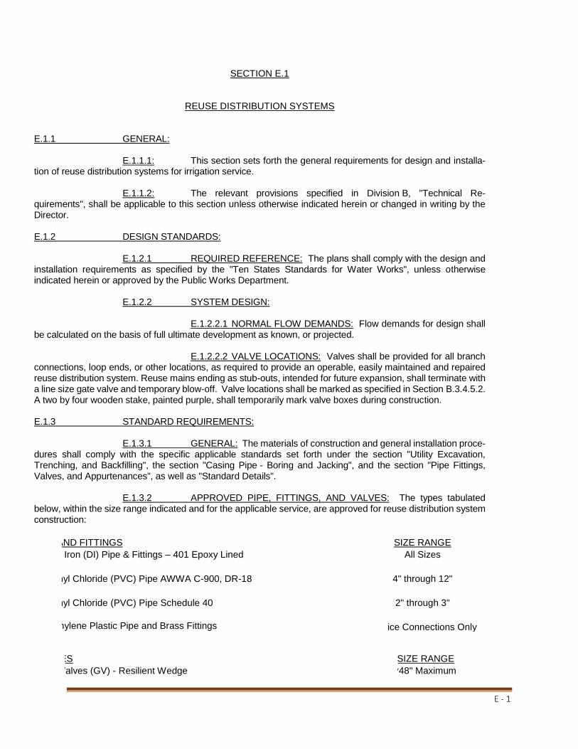
E - 1
SECTION E.1
REUSE DISTRIBUTION SYSTEMS E.1.1 GENERAL: E.1.1.1: This section sets forth the general requirements for design and installa-tion of reuse distribution systems for irrigation service. E.1.1.2: The relevant provisions specified in Division B, "Technical Re-quirements", shall be applicable to this section unless otherwise indicated herein or changed in writing by the Director. E.1.2 DESIGN STANDARDS: E.1.2.1 REQUIRED REFERENCE: The plans shall comply with the design and installation requirements as specified by the "Ten States Standards for Water Works", unless otherwise indicated herein or approved by the Public Works Department. E.1.2.2 SYSTEM DESIGN: E.1.2.2.1 NORMAL FLOW DEMANDS: Flow demands for design shall be calculated on the basis of full ultimate development as known, or projected. E.1.2.2.2 VALVE LOCATIONS: Valves shall be provided for all branch connections, loop ends, or other locations, as required to provide an operable, easily maintained and repaired reuse distribution system. Reuse mains ending as stub-outs, intended for future expansion, shall terminate with a line size gate valve and temporary blow-off. Valve locations shall be marked as specified in Section B.3.4.5.2. A two by four wooden stake, painted purple, shall temporarily mark valve boxes during construction. E.1.3 STANDARD REQUIREMENTS: E.1.3.1 GENERAL: The materials of construction and general installation proce-dures shall comply with the specific applicable standards set forth under the section "Utility Excavation, Trenching, and Backfilling", the section "Casing Pipe - Boring and Jacking", and the section "Pipe Fittings, Valves, and Appurtenances", as well as "Standard Details". E.1.3.2 APPROVED PIPE, FITTINGS, AND VALVES: The types tabulated below, within the size range indicated and for the applicable service, are approved for reuse distribution system construction:
PIPE AND FITTINGS SIZE RANGE
Ductile Iron (DI) Pipe & Fittings – 401 Epoxy Lined All Sizes
Polyvinyl Chloride (PVC) Pipe AWWA C-900, DR-18 4" through 12"
Polyvinyl Chloride (PVC) Pipe Schedule 40 2" through 3"
Polyethylene Plastic Pipe and Brass Fittings Service Connections Only
VALVES SIZE RANGE
Gate Valves (GV) - Resilient Wedge *48" Maximum

E - 2
E.1.3.3 RESTRAINED JOINTS: Pressure piping fittings and other items requiring restraint shall be braced with thrust blocks or other restraining assemblies, as specified under Sec-tion B.3. Said restraining devices shall be designed for the maximum pressure condition (testing) and the safe bearing loads for horizontal thrust, if thrust blocking is used. E.1.3.4 PIPE DEPTH AND PROTECTION: The standard minimum cover for reuse distribution systems shall be three feet from the top of the pipe to finish grade. However, should this design not be feasible, protective concrete slabs may be required over the pipe within the limits of the lesser cover. Where waterways, canals, ditches, or other cuts are crossed, protective concrete slabs may also be required across and to ten feet each side of the bottom. Additionally, approved utility crossing signs shall be placed on the pipe alignment at each side of the canal, etc. E.1.3.5 CONNECTIONS AT STRUCTURES: Where pipes are to extend into or through structures, flexible joints shall be provided at the wall face. E.1.3.6 SPECIAL EXTERIOR PROTECTION FOR CORROSION: Extra protection shall be provided for underground ductile iron pipe and fittings within areas of severe corrosive con-ditions. This shall be accomplished by the installation of polyethylene encasement, AWWA C105, as specified in Section B, through the area of concern. The soil test evaluation to determine the necessity for extra protection in suspect areas shall be as set forth in ANSI Standard A21.5. Additionally, where other existing utilities are known to be cathodically protected, ductile iron pipe crossing said utility shall be protected for a distance of 20 feet to each side, and when installed parallel to and within ten feet of, protection shall also be provided. Steel pipe shall not be installed in severe corrosion areas without appropriate protection. E.1.3.7 AIR VENTING AND BLOW-OFFS: Where the reuse main profile is such that air pockets or entrapment could occur, resulting in flow blockage, methods for air releases shall be provided. Air venting capabilities shall be provided for distribution mains by appropriately placing blow-offs or other manual devices. At critical points on major mains, automatic air release assemblies shall be installed, with valves as specified under Section B. All dead-end reuse mains, temporary or permanent, shall be equipped with a manually operated blow-off at the terminal. E.1.3.8 IDENTIFICATION AND TRACER GROUND WIRE: All proposed underground water mains (2” diameter and over) shall be marked with a continuous metallic tape located directly over the pipe, tape should be between 12 inches to 18 inches below proposed finish grade. Said tape shall be a minimum of two inches in width and shall be metallic backed, blue and marked “WATER MAIN BURIED BELOW.” Tracer ground wire shall consist of two wires, No.10 solid copper coated purple. Wires shall be placed directly over the PVC pipe and into the valve box with four feet (minimum) of coiled ends (pigtails). (See Standard Details – Detail 44 & 45) E.1.3.9 SERVICE CONNECTIONS: Connections to reuse mains shall be made by drilling the appropriate size hole and installing of service saddles or in-line fittings. A corporation stop shall be placed at the saddle or fitting, with the service line extended to the property line, perpendicular to said line, and terminating with a lock wing ball valve curb stop (RE: Section B for material specifications and Detail Sheet for "Typical Service Connection Details"). The minimum size for reuse service connection shall be one inch. On curbed streets, the exact location for each installed service shall be marked by neatly painting a purple two-inch by four-inch stripe in the concrete curb; curb to be scored with a power saw prior to painting. Paint shall be as recommended for exterior concrete application. Where no curb exists or is planned, locations shall be adequately marked by a method approved by the Public Works Department. Reuse services shall terminate at property corners, secured to a two by four stake painted purple. Cross-Connection between reclaimed water and potable water is strictly prohibited.
*Side actuators made be required above 16"
Corporation Stops and Curb Stops Service Connections Only

E - 3
E.1.3.10 BULK WATER METER APPLICATIONS (THREE INCH AND LARGER): All bulk water meters to be installed to New Port Richey Utilities specifications (see detail specification sheet). Meters will be the turbine-type unless otherwise specified by the Director. E.1.3.11 BACKFLOW PREVENTION: The potable connections for areas receiving reuse irrigation water will be provided with a DCVA. E.1.3.12: All installed underground reuse mains shall be marked with a continuous tape located directly over the pipe 12 inches to 18 inches below grade. Said tape shall be a minimum of two inches in width and shall be metallic-backed, purple, and marked "REUSE MAIN BURIED BELOW". E.1.4 TESTING: E.1.4.1: The Contractor shall perform hydrostatic testing of all reuse distribution systems, as set forth in the following, and shall conduct said tests in the presence of representatives of the Engineer and the Public Works Department, with two days' advance notice provided. E.1.4.2: Testing shall not proceed until restraining devices have been installed. All piping shall be thoroughly cleaned and flushed prior to testing to clear the lines of all foreign matter. While the piping is being filled with water, care shall be exercised to permit the escape of air from extremities of the test section, with additional release cocks provided, if required. E.1.4.3: Hydrostatic testing shall be performed at 150 psi pressure, unless otherwise approved by the Director for a period of not less than two hours. Testing shall be in accordance with the applicable provisions as set forth in Section 13 of AWWA Standard C600. The allowable rate of leakage shall be less than the number of gallons per hour determined by the following formula: SD (P)½ L = ____________ 133,200 L = Allowable leakage in gallons per hour S = Length of pipe tested, feet D = Nominal diameter of the pipe in inches P = average test pressure maintained during the leakage test in pounds per square inch gauge E.1.4.4: The testing procedure shall include the continued application of the speci-fied pressure to the test system for the two-hour period by way of a pump taking supply from a container suitable for measuring water loss. The amount of loss shall be determined by measuring the volume displaced from said container. E.1.4.5: Should the test fail, necessary repairs shall be accomplished by the Contractor and the test repeated until within the established limits. The Contractor shall furnish the necessary labor, water, pumps, gauges, and all other items required to conduct the required reuse distribution system testing and perform necessary repairs.

DIVISION F
CITY – STANDARD DETAILS

PROVIDED FOR INFORMATIONAL
PURPOSES ONLY.
NO MODIFICATIONS WITHOUT
WRITTEN NPRPW APPROVAL

PROVIDED FOR INFORMATIONAL
PURPOSES ONLY.
NO MODIFICATIONS WITHOUT
WRITTEN NPRPW APPROVAL

PROVIDED FOR INFORMATIONAL
PURPOSES ONLY.
NO MODIFICATIONS WITHOUT
WRITTEN NPRPW APPROVAL
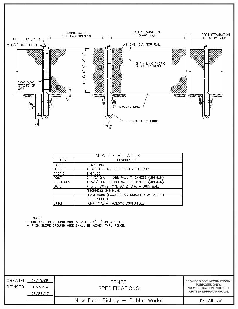
PROVIDED FOR INFORMATIONAL
PURPOSES ONLY.
NO MODIFICATIONS WITHOUT
WRITTEN NPRPW APPROVAL

PROVIDED FOR INFORMATIONAL
PURPOSES ONLY.
NO MODIFICATIONS WITHOUT
WRITTEN NPRPW APPROVAL

PROVIDED FOR INFORMATIONAL
PURPOSES ONLY.
NO MODIFICATIONS WITHOUT
WRITTEN NPRPW APPROVAL
24"
36"
#57 WHITE STONE
18"

PROVIDED FOR INFORMATIONAL
PURPOSES ONLY.
NO MODIFICATIONS WITHOUT
WRITTEN NPRPW APPROVAL

PROVIDED FOR INFORMATIONAL
PURPOSES ONLY.
NO MODIFICATIONS WITHOUT
WRITTEN NPRPW APPROVAL
24"
36"
18"

PROVIDED FOR INFORMATIONAL
PURPOSES ONLY.
NO MODIFICATIONS WITHOUT
WRITTEN NPRPW APPROVAL

PROVIDED FOR INFORMATIONAL
PURPOSES ONLY.
NO MODIFICATIONS WITHOUT
WRITTEN NPRPW APPROVAL

PROVIDED FOR INFORMATIONAL
PURPOSES ONLY.
NO MODIFICATIONS WITHOUT
WRITTEN NPRPW APPROVAL

PROVIDED FOR INFORMATIONAL
PURPOSES ONLY.
NO MODIFICATIONS WITHOUT
WRITTEN NPRPW APPROVAL

PROVIDED FOR INFORMATIONAL
PURPOSES ONLY.
NO MODIFICATIONS WITHOUT
WRITTEN NPRPW APPROVAL

PROVIDED FOR INFORMATIONAL
PURPOSES ONLY.
NO MODIFICATIONS WITHOUT
WRITTEN NPRPW APPROVAL

PROVIDED FOR INFORMATIONAL
PURPOSES ONLY.
NO MODIFICATIONS WITHOUT
WRITTEN NPRPW APPROVAL

PROVIDED FOR INFORMATIONAL
PURPOSES ONLY.
NO MODIFICATIONS WITHOUT
WRITTEN NPRPW APPROVAL

PROVIDED FOR INFORMATIONAL
PURPOSES ONLY.
NO MODIFICATIONS WITHOUT
WRITTEN NPRPW APPROVAL

PROVIDED FOR INFORMATIONAL
PURPOSES ONLY.
NO MODIFICATIONS WITHOUT
WRITTEN PNPRPW APPROVAL

PROVIDED FOR INFORMATIONAL
PURPOSES ONLY.
NO MODIFICATIONS WITHOUT
WRITTEN PNPRPW APPROVAL

PROVIDED FOR INFORMATIONAL
PURPOSES ONLY.
NO MODIFICATIONS WITHOUT
WRITTEN NPRPW APPROVAL

PROVIDED FOR INFORMATIONAL
PURPOSES ONLY.
NO MODIFICATIONS WITHOUT
WRITTEN NPRPW APPROVAL

PROVIDED FOR INFORMATIONAL
PURPOSES ONLY.
NO MODIFICATIONS WITHOUT
WRITTEN NPRPW APPROVAL

PURPOSES ONLY.
PROVIDED FOR INFORMATIONAL
NO MODIFICATIONS WITHOUT
WRITTEN NPRPW APPROVAL

PROVIDED FOR INFORMATIONAL
PURPOSES ONLY.
NO MODIFICATIONS WITHOUT
WRITTEN NPRPW APPROVAL

PROVIDED FOR INFORMATIONAL
PURPOSES ONLY.
NO MODIFICATIONS WITHOUT
WRITTEN NPRPW APPROVAL

PROVIDED FOR INFORMATIONAL
PURPOSES ONLY.
NO MODIFICATIONS WITHOUT
WRITTEN NPRPW APPROVAL

PROVIDED FOR INFORMATIONAL
PURPOSES ONLY.
NO MODIFICATIONS WITHOUT
WRITTEN NPRPW APPROVAL

PROVIDED FOR INFORMATIONAL
PURPOSES ONLY.
NO MODIFICATIONS WITHOUT
WRITTEN NPRPW APPROVAL

PROVIDED FOR INFORMATIONAL
PURPOSES ONLY.
NO MODIFICATIONS WITHOUT
WRITTEN NPRPW APPROVAL
36" MIN.
EXISTING PAVEMENT
EXISTING BASE
0.40 CY CONC. MIN. (3000 P.S.I.)
24" MIN.
UNDISTURBEDSOIL
48" MIN.
BE USED FOR PROTECTION OFFIRE HYDRANTS & BACK FLOW
PAINT SAFETY YELLOW
6" SCH. 40 STEEL PIPE (MIN.) SHALL
EXISTING GRADE
HYDRANT GUARD
45°
4'0" (TYP.)
(TYP.)
INSTALLATION
TYPICAL HYDRANT GUARD
LAYOUT
AND SET IN CONCRETE.BOTH ARE TO BE FILLED WITH
PREVENTION ASSEMBLIES.

PROVIDED FOR INFORMATIONAL
PURPOSES ONLY.
NO MODIFICATIONS WITHOUT
WRITTEN NPRPW APPROVAL

PROVIDED FOR INFORMATIONAL
PURPOSES ONLY.
NO MODIFICATIONS WITHOUT
WRITTEN NPRPW APPROVAL

PROVIDED FOR INFORMATIONAL
PURPOSES ONLY.
NO MODIFICATIONS WITHOUT
WRITTEN NPRPW APPROVAL

PROVIDED FOR INFORMATIONAL
PURPOSES ONLY.
NO MODIFICATIONS WITHOUT
WRITTEN NPRPW APPROVAL

PROVIDED FOR INFORMATIONAL
PURPOSES ONLY.
NO MODIFICATIONS WITHOUT
WRITTEN NPRPW APPROVAL

PROVIDED FOR INFORMATIONAL
PURPOSES ONLY.
NO MODIFICATIONS WITHOUT
WRITTEN NPRPW APPROVAL

PROVIDED FOR INFORMATIONAL
PURPOSES ONLY.
NO MODIFICATIONS WITHOUT
WRITTEN NPRPW APPROVAL

PROVIDED FOR INFORMATIONAL
PURPOSES ONLY.
NO MODIFICATIONS WITHOUT
WRITTEN NPRPW APPROVAL

PROVIDED FOR INFORMATIONAL
PURPOSES ONLY.
NO MODIFICATIONS WITHOUT
WRITTEN NPRPW APPROVAL

PROVIDED FOR INFORMATIONAL
PURPOSES ONLY.
NO MODIFICATIONS WITHOUT
WRITTEN NPRPW APPROVAL

PROVIDED FOR INFORMATIONAL
PURPOSES ONLY.
NO MODIFICATIONS WITHOUT
WRITTEN NPRPW APPROVAL

PROVIDED FOR INFORMATIONAL
PURPOSES ONLY.
NO MODIFICATIONS WITHOUT
WRITTEN NPRPW APPROVAL

PROVIDED FOR INFORMATIONAL
PURPOSES ONLY.
NO MODIFICATIONS WITHOUT
WRITTEN NPRPW APPROVAL

PROVIDED FOR INFORMATIONAL
PURPOSES ONLY.
NO MODIFICATIONS WITHOUT
WRITTEN NPRPW APPROVAL

PROVIDED FOR INFORMATIONAL
PURPOSES ONLY.
NO MODIFICATIONS WITHOUT
WRITTEN NPRPW APPROVAL

PROVIDED FOR INFORMATIONAL
PURPOSES ONLY.
NO MODIFICATIONS WITHOUT
WRITTEN NPRPW APPROVAL

PROVIDED FOR INFORMATIONAL
PURPOSES ONLY.
NO MODIFICATIONS WITHOUT
WRITTEN NPRPW APPROVAL

PROVIDED FOR INFORMATIONAL
PURPOSES ONLY.
NO MODIFICATIONS WITHOUT
WRITTEN NPRPW APPROVAL


PROVIDED FOR INFORMATIONAL
PURPOSES ONLY.
NO MODIFICATIONS WITHOUT
WRITTEN NPRPW APPROVAL

PROVIDED FOR INFORMATIONAL
PURPOSES ONLY.
NO MODIFICATIONS WITHOUT
WRITTEN NPRPW APPROVAL

PROVIDED FOR INFORMATIONAL
PURPOSES ONLY.
NO MODIFICATIONS WITHOUT
WRITTEN NPRPW APPROVAL

PROVIDED FOR INFORMATIONAL
PURPOSES ONLY.
NO MODIFICATIONS WITHOUT
WRITTEN NPRPW APPROVAL

PROVIDED FOR INFORMATIONAL
PURPOSES ONLY.
NO MODIFICATIONS WITHOUT
WRITTEN NPRPW APPROVAL

PROVIDED FOR INFORMATIONAL
PURPOSES ONLY.
NO MODIFICATIONS WITHOUT
WRITTEN NPRPW APPROVAL
UN11956XX

PROVIDED FOR INFORMATIONAL
PURPOSES ONLY.
NO MODIFICATIONS WITHOUT
WRITTEN NPRPW APPROVAL

PROVIDED FOR INFORMATIONAL
PURPOSES ONLY.
NO MODIFICATIONS WITHOUT
WRITTEN NPRPW APPROVAL

PROVIDED FOR INFORMATIONAL
PURPOSES ONLY.
NO MODIFICATIONS WITHOUT
WRITTEN NPRPW APPROVAL

PROVIDED FOR INFORMATIONAL
PURPOSES ONLY.
NO MODIFICATIONS WITHOUT
WRITTEN NPRPW APPROVAL

PROVIDED FOR INFORMATIONAL
PURPOSES ONLY.
NO MODIFICATIONS WITHOUT
WRITTEN NPRPW APPROVAL

PROVIDED FOR INFORMATIONAL
PURPOSES ONLY.
NO MODIFICATIONS WITHOUT
WRITTEN NPRPW APPROVAL

PROVIDED FOR INFORMATIONAL
PURPOSES ONLY.
NO MODIFICATIONS WITHOUT
WRITTEN NPRPW APPROVAL

PROVIDED FOR INFORMATIONAL
PURPOSES ONLY.
NO MODIFICATIONS WITHOUT
WRITTEN NPRPW APPROVAL

DIVISION G
CITY – MISCELLANEOUS DETAILS

PROVIDED FOR INFORMATIONAL
PURPOSES ONLY.
NO MODIFICATIONS WITHOUT
WRITTEN NPRPW APPROVAL
GATEWAY TOTROPICAL
FLORIDA


PROVIDED FOR INFORMATIONAL
PURPOSES ONLY.
NO MODIFICATIONS WITHOUT
WRITTEN NPRPW APPROVAL


PROVIDED FOR INFORMATIONAL
PURPOSES ONLY.
NO MODIFICATIONS WITHOUT
WRITTEN NPRPW APPROVAL
*


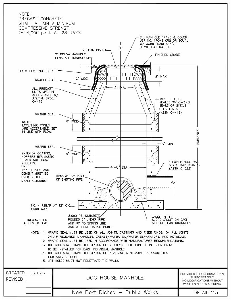
PROVIDED FOR INFORMATIONAL
PURPOSES ONLY.
NO MODIFICATIONS WITHOUT
WRITTEN NPRPW APPROVAL

PROVIDED FOR INFORMATIONAL
PURPOSES ONLY.
NO MODIFICATIONS WITHOUT
WRITTEN NPRPW APPROVAL

PROVIDED FOR INFORMATIONAL
PURPOSES ONLY.
NO MODIFICATIONS WITHOUT
WRITTEN NPRPW APPROVAL


PROVIDED FOR INFORMATIONAL
PURPOSES ONLY.
NO MODIFICATIONS WITHOUT
WRITTEN NPRPW APPROVAL