standard technical specifications for utilities and ... · standard technical specifications for....
TRANSCRIPT

Standard Technical Specifications for
Utilities and Related Construction August 2015
TABLE OF CONTENTS
8/24/15 TOC-1 PC-STS
DIVISION 00 – PROCUREMENT AND CONTRACTING REQUIREMENTS 00 75 00 Special Provisions and Supplemental Technical Specifications DIVISION 01 – GENERAL REQUIREMENTS 01 32 33 Color Audio-Video Construction Records 01 35 00 Special Project Procedures 01 42 01 Reference Standards and Definitions 01 45 17 Pipeline Pressure and Leakage Testing Requirements 01 55 26 Traffic Regulation 01 57 00 Control of Work 01 57 13 Erosion and Sedimentation Control 01 58 01 Project Identification Signs 01 78 39 Project Record Documents DIVISION 02 – EXISTING CONDITIONS (NOT USED) DIVISION 03 – CONCRETE 03 10 01 Concrete Materials DIVISION 04 – MASONRY (NOT USED) DIVISION 05 – METALS (NOT USED) DIVISION 06 – WOOD, PLASTICS, AND COMPOSITES (NOT USED) DIVISION 07 – THERMAL AND MOISTURE PROTECTION (NOT USED) DIVISION 08 – OPENINGS (NOT USED) DIVISION 09 – FINISHES 09 91 00 Painting and Protective Coatings
TABLE OF CONTENTS
8/24/15 TOC-2 PC-STS
DIVISION 10 – SPECIALTIES (NOT USED) DIVISION 11 – EQUIPMENT (NOT USED) DIVISION 12 – FURNISHINGS (NOT USED) DIVISION 13 – SPECIAL CONSTRUCTION (NOT USED) DIVISION 14 – CONVEYING EQUIPMENT (NOT USED) DIVISION 21 – FIRE SUPPRESSION (NOT USED) DIVISION 22 – PLUMBING (NOT USED) DIVISION 23 – HEATING, VENTILATING, AND AIR CONDITIONING (HVAC) (NOT USED) DIVISION 25 – INTEGRATED AUTOMATION (NOT USED) DIVISION 26 – ELECTRICAL (NOT USED) DIVISION 27 – COMMUNICATIONS (NOT USED) DIVISION 28 – ELECTRONIC SAFETY AND SECURITY (NOT USED) DIVISION 31 – EARTHWORK 31 23 33 Excavation and Backfill for Pipes 31 23 34 Excavation and Backfill for Structures DIVISION 32 – EXTERIOR IMPROVEMENTS 32 12 01 Stabilized and Asphalt Roadway Restoration 32 13 01 Concrete Sidewalks, Driveways, and Gutters 32 92 01 Seeding and Sodding DIVISION 33 – UTILITIES 33 01 31 Sanitary Sewer Cured in Place Pipelining 33 01 32 Sanitary Sewer Cleaning and Televising 33 01 33 Manhole Rehabilitation 33 01 34 Sanitary Sewer Pipe Repairs

TABLE OF CONTENTS
8/24/15 TOC-3 PC-STS
33 01 35 Multi-component Stress Panel Manhole Liner System 33 01 36 Urethane/ Epoxy, Polyurea Manhole Liner System 33 01 37 Polyurethane Manhole Liner System 33 01 38 Polymorphic Resin Manhole Liner System 33 01 39 Calcium Aluminate Manhole Liner System 33 01 40 CIPP Structural Lateral Connection Lining 33 05 20 Jacking and Boring 33 05 21 Horizontal Directional Drilling Standard Small Diameter Installations 33 05 22 Horizontal Directional Drilling
Subaqueous Crossings and Large Diameter Installations 33 11 01 Potable Water Main Piping and Appurtenances 33 13 01 Disinfection of Potable Water Mains 33 32 00 Submersible Wastewater Pumping Stations 33 33 01 Gravity Sewers 33 34 00 Sanitary Sewage Force Mains and Appurtenances 33 35 01 Reclaimed Water Main Piping and Appurtenances 33 39 00 Sanitary Sewer Structures DIVISION 34 –TRANSPORTATION (NOT USED) DIVISION 35 – WATERWAY AND MARINE CONSTRUCTION (NOT USED) DIVISION 40 – PROCESS INTEGRATION 40 95 01 Wastewater Pump Station SCADA Remote Telemetry Unit (RTU) DIVISION 41 – MATERIAL PROCESSING AND HANDLING EQUIPMENT (NOT USED) DIVISION 42 – PROCESS HEATING, COOLING, AND DRYING EQUIPMENT (NOT USED)

TABLE OF CONTENTS
8/24/15 TOC-4 PC-STS
DIVISION 43 – PROCESS GAS AND LIQUID HANDLING, PURIFICATION, AND STORAGE EQUIPMENT (NOT USED)
DIVISION 44 – POLLUTION CONTROL EQUIPMENT(NOT USED) DIVISION 45 – INDUSTRY SPECIFICATION MANUFACTURING EQUIPMENT(NOT USED) DIVISION 48 – ELECTRICAL POWER GENERATION (NOT USED) 48 11 30 Standby Diesel Generators
8/24/15 PC – Job # Special Provisions and Supplemental Technical Specifications
00 75 00-1
SECTION 00 75 00 1 2
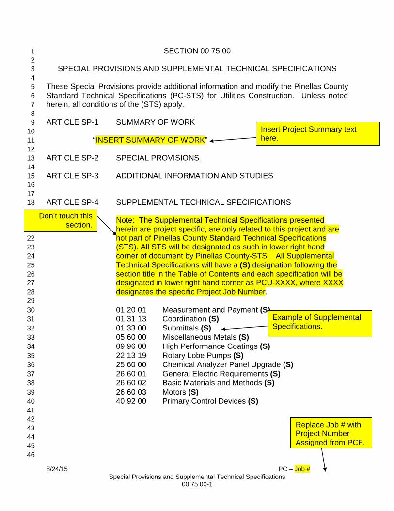
SPECIAL PROVISIONS AND SUPPLEMENTAL TECHNICAL SPECIFICATIONS 3 4 These Special Provisions provide additional information and modify the Pinellas County 5 Standard Technical Specifications (PC-STS) for Utilities Construction. Unless noted 6 herein, all conditions of the (STS) apply. 7 8 ARTICLE SP-1 SUMMARY OF WORK 9
10 “INSERT SUMMARY OF WORK” 11 12
ARTICLE SP-2 SPECIAL PROVISIONS 13 14 ARTICLE SP-3 ADDITIONAL INFORMATION AND STUDIES 15 16 17 ARTICLE SP-4 SUPPLEMENTAL TECHNICAL SPECIFICATIONS 18
19 Note: The Supplemental Technical Specifications presented 20 herein are project specific, are only related to this project and are 21 not part of Pinellas County Standard Technical Specifications 22 (STS). All STS will be designated as such in lower right hand 23 corner of document by Pinellas County-STS. All Supplemental 24 Technical Specifications will have a (S) designation following the 25 section title in the Table of Contents and each specification will be 26 designated in lower right hand corner as PCU-XXXX, where XXXX 27 designates the specific Project Job Number. 28
29 01 20 01 Measurement and Payment (S) 30 01 31 13 Coordination (S) 31 01 33 00 Submittals (S) 32 05 60 00 Miscellaneous Metals (S) 33 09 96 00 High Performance Coatings (S) 34 22 13 19 Rotary Lobe Pumps (S) 35 25 60 00 Chemical Analyzer Panel Upgrade (S) 36 26 60 01 General Electric Requirements (S) 37 26 60 02 Basic Materials and Methods (S) 38 26 60 03 Motors (S) 39 40 92 00 Primary Control Devices (S) 40
41 42 43 44 45 46
Insert Project Summary text here.
Example of Supplemental Specifications.
Don’t touch this section.
Replace Job # with Project Number Assigned from PCF.
8/24/15 PC – Job # Special Provisions and Supplemental Technical Specifications
00 75 00-2
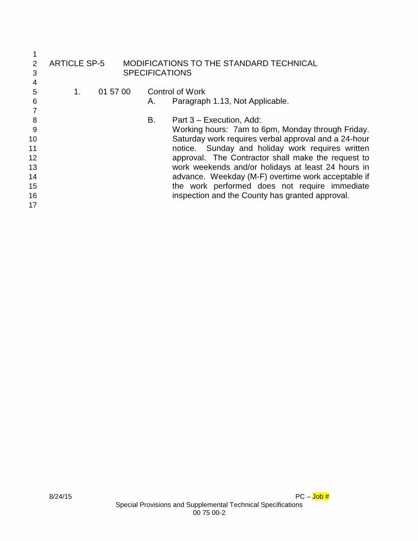
1 ARTICLE SP-5 MODIFICATIONS TO THE STANDARD TECHNICAL 2
SPECIFICATIONS 3 4 1. 01 57 00 Control of Work 5 A. Paragraph 1.13, Not Applicable. 6 7
B. Part 3 – Execution, Add: 8 Working hours: 7am to 6pm, Monday through Friday. 9 Saturday work requires verbal approval and a 24-hour 10 notice. Sunday and holiday work requires written 11 approval. The Contractor shall make the request to 12 work weekends and/or holidays at least 24 hours in 13 advance. Weekday (M-F) overtime work acceptable if 14 the work performed does not require immediate 15 inspection and the County has granted approval. 16
17

8/24/15 PC – Job # Special Provisions and Supplemental Technical Specifications
00 75 00-3
TECHNICAL SPECIFICATION CHECKLIST 1
Project Name: Insert Title 2 Project Number: XXXX 3
4 The following sections of the Standard Technical Specifications will apply to this 5 contract if marked “X” as shown below: 6 7 00 75 00 X Special Provisions and Supplemental Technical Specifications 01 32 33 Color Audio-Video Construction Records 01 35 00 Special Project Procedures 01 42 01 Reference Standards and Definitions 01 45 17 Pipeline Testing Requirements 01 55 26 Traffic Regulation 01 57 00 Control of Work 01 57 13 Erosion and Sedimentation Control 01 58 01 Project Identification Signs 01 78 39 X Project Record Documents 03 10 01 Concrete Materials 09 91 00 Painting and Protective Coatings 31 23 33 Excavation and Backfill for Pipes 31 23 34 Excavation and Backfill for Structures 32 12 01 Stabilized and Asphalt Roadway Restoration 32 13 01 Concrete Sidewalks, Driveways and Gutters 32 92 01 Seeding and Sodding 33 01 31 Sanitary Sewer Cured in Place Pipelining 33 01 32 Sanitary Sewer Cleaning and Televising 33 01 33 Manhole Rehabilitation 33 01 34 Sanitary Sewer Pipe Repairs 33 01 35 Multi-Component Stress Panel Manhole Liner System 33 01 36 Urethane/Epoxy, Polyurea Manhole Liner System 33 01 37 Polyurethane Manhole Liner System 33 01 38 Polymorphic Resin Manhole Liner System 33 01 39 Calcium Aluminate Manhole Liner System 33 01 40 CIPP Structural Lateral Connection Lining 33 05 20 Jacking and Boring 33 05 21 Horizontal Directional Drilling
33 05 22 Horizontal Directional Drilling – Subaqueous Crossings and Large Diameter Installations
33 11 01 Potable Water Main Piping and Appurtenances 33 13 01 Disinfection of Potable Water Mains 33 32 00 Submersible Wastewater Pumping Stations 33 33 01 Gravity Sewers 33 34 00 Sanitary Sewage Force Mains and Appurtenances 33 35 01 Reclaimed Water Main Piping and Appurtenances 33 39 00 Sanitary Utility Sewerage Structures
Insert Title and Project Number Assigned from PCF.
8/24/15 PC – Job # Special Provisions and Supplemental Technical Specifications
00 75 00-4
40 95 01 Wastewater Pump Station SCADA Remote Telemetry Unit (RTU) 48 11 30 Standby Diesel Generators 13 34 19 Metal Building Systems
END OF SECTION 1

COLOR AUDIO-VIDEO CONSTRUCTION RECORDS 7/07/15 01 32 33 -1 PC-STS
SECTION 01 32 33 1 2
COLOR AUDIO-VIDEO CONSTRUCTION RECORDS 3 4 5 PART 1 - GENERAL 6 7 1.01 DESCRIPTION 8 9
A. Audio/Video DVDs of all work areas in the Contract shall be prepared by 10 the Contractor. 11
12 B. Contractor To Prepare Audio/Video Recording - Prior to commencing the 13
Work, the Contractor shall have a continuous color audio/video recording 14 taken along the entire length of the Project including all affected project 15 areas. Streets, easements, rights-of way, lots or construction sites within 16 the Project must be recorded to serve as a record of pre-construction 17 conditions. Two copies of the recordings and video log shall be submitted 18 to the County. The ENGINEER shall designate those areas, if any, to be 19 omitted from or added to the audio-visual coverage. All DVDs and written 20 records shall become property of the County. 21
22 C. Scheduling Of Audio/Video Recording - No construction shall begin prior 23
to review and approval of the recordings covering the Project construction 24 area(s) by the County. The County shall have the authority to reject all or 25 any portion of a recording not conforming to specifications and order that 26 it be redone at no additional charge. The Contractor shall reschedule 27 unacceptable coverage within seven days after being notified. Recordings 28 shall not be made more than 30 days prior to construction in any area. 29
30 D. Professional Videographers - The Contractor shall engage the services of 31
a professional videographer known to be skilled and regularly engaged in 32 the business of preconstruction color audio-video documentation. The 33 videographer through the Contractor shall furnish to the Engineer a list of 34 all equipment to be used for the audio-video recording, i.e., 35 manufacturer’s name, model number, specifications and other pertinent 36 information. 37
38 E. Additional information to be furnished by the videographer is the names 39
and addresses of two references that the videographer has performed 40 color audio-video taping for on projects of a similar nature within the last 41 12 months. Engineer’s approval of the selected videographer is required 42 prior to taking first audio-video recording. 43
44 F. Equipment - All equipment, accessories, materials and labor to perform 45
this service shall be finished by the Contractor. The total audio-video 46
COLOR AUDIO-VIDEO CONSTRUCTION RECORDS 7/07/15 01 32 33 -2 PC-STS
system shall reproduce bright, sharp, clear pictures with accurate colors 1 and shall be free from distortion, tearing, rolls or any other form of 2 imperfection. The audio portion of the recording shall reproduce the 3 commentary of the camera operator with proper volume, clarity and be 4 free from distortion and interruptions. In some instances, audio-video 5 coverage may be required in areas not accessible by conventional 6 wheeled vehicles. Such coverage shall be obtained by walking. The color 7 video camera used in the recording shall be of Industrial Grade and shall 8 have EIA Standard NTSC type color - 1.0V 75 OHMS. Video output from 9 camera shall be capable of horizontal resolution of 350 lines at center and 10 utilize a minimum of 8:1 zoom with a 2/3” Newvicon tube or CCD pick-up 11 element for optimum color imagery plus minimum lag through of one foot 12 candle. The recording shall be transferred to DVDs compatible for 13 playback with any Region 1 American TV Standard DVD player. 14
15 G. Recorded Information, Audio - Each recording shall begin with the current 16
date, project name and be followed by the general location, i.e., viewing 17 side and direction of progress. Accompanying the video recording shall 18 be a corresponding and simultaneously recorded audio recording. This 19 audio recording, exclusively containing the commentary of the camera 20 operator or aide, shall assist in viewer orientation and in any needed 21 identification, differentiation, clarification, or objective description of the 22 features being shown in the video portion of the recording. The audio 23 recording shall also be free from any conversations. 24
25 H. Recorded Information - Video - All video recordings must continuously 26
display transparent digital information to include the date and time of 27 recording. The date information shall contain the month, day and year. 28 The time information shall contain the hour, minutes and seconds. 29 Additional information shall be displayed periodically. Such information 30 shall include, but not be limited to, project name, contract number, 31 direction of travel and the viewing side. This transparent information shall 32 appear on the extreme upper left hand third of the screen. Camera pan, 33 tilt, zoom-in and zoom-out rates shall be sufficiently controlled such that 34 recorded objects will be clearly viewed during video playback. In addition, 35 all other camera and recording system controls, such as lens focus and 36 aperture, video level, pedestal, chrome, white balance, and electrical 37 focus shall be properly controlled or adjusted to maximize picture quality. 38 The construction documentation shall be recorded in SP mode. 39
40 I. Viewer Orientation - The audio and video portions of the recording shall 41
maintain viewer orientation. To this end, overall establishing views of all 42 visible house and business addresses shall be utilized. In areas where 43 the proposed construction location will not be readily apparent to the video 44 viewer, highly visible yellow flags shall be placed, by the Contractor, in 45 such a fashion as to clearly indicate the proposed centerline of 46

COLOR AUDIO-VIDEO CONSTRUCTION RECORDS 7/07/15 01 32 33 -3 PC-STS
construction. When conventional wheeled vehicles are used as 1 conveyances for the recording system, the vertical distance between the 2 camera lens and the ground shall not exceed 10 feet. The camera shall 3 be firmly mounted such that transport of the camera during the recording 4 process will not cause an unsteady picture. 5
6 J. Lighting - All taping shall be done during time of good visibility. No taping 7
shall be done during precipitation, mist or fog. The recording shall only be 8 done when sufficient sunlight is present to properly illuminate the subjects 9 of recording and to produce bright, sharp video recordings of those 10 subjects. 11
12 K. Speed Of Travel - The average rate of travel during a particular segment 13
of coverage shall be directly proportional to the number, size and value of 14 the surface features within that construction areas zone of influence. The 15 rate of speed in the general direction of travel of the vehicle used during 16 taping shall not exceed 44 feet per minute. 17
18 L. Video Log/Index - All DVDs shall be permanently labeled and shall be 19
properly identified by number and project title. Each DVD shall have a log 20 of its contents. The log shall describe the various segments of coverage 21 contained on the DVD in terms of the names of the streets or location of 22 easements, coverage beginning and end, directions of coverage, video 23 unit counter numbers, engineering survey or coordinate values (if 24 reasonably available) and the date. 25
26 M. Area Of Coverage - Recording coverage shall include all surface features 27
located within the zone of influence of construction supported by 28 appropriate audio coverage. Such coverage shall include, but not be 29 limited to, existing driveways, sidewalks, curbs, pavements, drainage 30 system features, mailboxes, landscaping, culverts, fences, signs, 31 Contractor staging areas, adjacent structures, etc. within the area covered 32 by the project. Of particular concern shall be the existence of any faults, 33 fractures, or defects. Coverage shall be limited to one side of the site, 34 street, easement or right-of-way at any one time. 35
36 N. Costs Of Video Services - The cost to complete the requirements under 37
this section shall be included in the contract items provided in the 38 proposal sheet. There is no separate pay item for this work. 39
40 PART 2 - PRODUCTS (NOT USED) 41 42 PART 3 - EXECUTION (NOT USED) 43 44
END OF SECTION 45

SPECIAL PROJECT PROCEDURES 8/24/15 01 35 00 - 1 PC-STS
SECTION 01 35 00 1 2
SPECIAL PROJECT PROCEDURES 3 4 PART 1 – GENERAL 5 6 1.01 EXISTING UTILITIES 7
8 A. Where existing utility lines (water, gas, telephone, power, etc.) are 9
intersected by proposed Work, the Contractor shall give a minimum of 10 forty-eight (48) hours notice to the owners of such utilities to permit them to 11 locate their lines prior to construction. The "Call Sunshine" Utility Notification 12 Center shall be contacted at 1-800-432-4770 at least forty-eight (48) hours 13 prior to start of excavation. Utilities, which are not members of the Utility 14 Notification Center, shall be contacted individually by the Contractor. 15
16 17
18 1.02 REPAIRS 19 20 A. WORK SCHEDULE AND EMERGENCY RESPONSE TIME 21 22
1. Emergency response by the Contractor will be required within one 23 hour of notice by telephone of required repair. The arrival of a repair 24 crew will be required within two hours of the Contractor's assessment 25 of the emergency situation. 26
27 2. The County will furnish the Contractor with the size, approximate 28
depth and general location of the proposed repair. The Contractor 29 shall be required to commence work on each assignment within ten 30 (10) consecutive calendar days after the date contained in each 31 written Notification to Proceed (unless such time is extended in 32 writing by the County), and will be obligated to pursue the Work on 33 each assignment with expeditious continuity until completion. The 34 County may order the Contractor to proceed with the Work at a faster 35 rate should a backlog of projects develop. In all cases, the 36 Contractor will be required to begin restoration work within two 37 working days and complete restoration work within ten (10) 38 consecutive calendar days following approval of the repair by the 39 Engineer. At the County's option, the maximum number of repairs 40 assigned to the Contractor at one time may be a maximum of fifteen 41 (15). 42
3. Each notification to proceed shall be accompanied by or preceded by 43 two copies of the appropriate Atlas Sheet(s), plus other information 44 including photographs (when available). 45
46
SPECIAL PROJECT PROCEDURES 8/24/15 01 35 00 - 2 PC-STS
B. Field Layout 1 2
1. The County supplied Atlas Sheet, street address and other pertinent 3 information will identify the general location of the repair. If there is 4 evidence of the defect visible from the surface, such as a depression, 5 the Contractor shall center his excavation on the evidence. If there is 6 any question as to the general location described by the County, the 7 Contractor shall approach the Engineer and address the questions 8 before beginning with the excavation. 9
10 C. Restoration Schedule 11 12 1. All restoration work must be completed within ten (10) consecutive 13
calendar days following approval of work at any given site. If the 14 restoration work does not progress to the satisfaction of the Engineer, 15 the Contractor may be directed to cease repair operations until such 16 time as the Engineer may deem the restoration work completed to a 17 degree permitting the resumption of repair work or the County may 18 elect to perform any such restoration work and bill the Contractor for 19 same. (At Engineer's discretion, payment shall be made by the 20 Contractor direct to the County, or a like amount deducted by the 21 County from monies due the Contractor for Work completed under 22 this Contract). 23
24 1.03 POTABLE WATER, RECLAIMED WATER AND SANITARY SEWER SYSTEM 25
CONSTRUCTION 26 27 A. Starting Project 28
29 1. The Contractor shall notify the Pinellas County Inspector and the 30
Engineer FORTY-EIGHT (48) HOURS prior to starting construction 31 (Saturday, Sunday and Holidays excluded). Upon notification, a 32 meeting will be scheduled between the Pinellas County Inspector 33 and the Contractor to review the plans. 34
35 B. Required Field Documents 36 37 1. The Contractor MUST have the following on the job site at all times 38
and readily available prior to any construction: 39 40 a. The Pinellas County approved "Contractor's Copy" of 41
construction plans stamped by the Florida Department of 42 Environmental Protection (FDEP) or other permitting agency. 43
44 2. All required permits including: 45
46
SPECIAL PROJECT PROCEDURES 8/24/15 01 35 00 - 3 PC-STS
a. F.D.O.T. 1 b. County 2 c. Florida Department of Environmental Protection (FDEP) 3
d. City/Municipality 4 5
C. If field conditions require deviation from the approved plans, the 6 Contractor shall notify the Project Engineer of the required change. The 7 Project Engineer will make the necessary changes and submit a revised 8 set of plans to the appropriate agency or agencies for approval. 9
10 D. All construction is subject to inspection and certain tasks require that the 11
Pinellas County Inspector be on the site to properly document the 12 procedure, test results and/or material used. On the occasions that the 13 Pinellas County Inspector is required on site to observe these tasks, 14 FORTY-EIGHT (48) hours advance notice will be required (Saturday, 15 Sunday and Holidays excluded). 16
17 E. Should the Contractor suspend work on any given project, the Contractor 18
shall provide written notification detailing the reason for the suspension to 19 Pinellas County within two business days. Additionally, forty-eight (48) 20 hours advance, written notice will be required for a restart of the project. 21
22 F. Should any materials be installed or backfilled prior to inspection by the 23
Pinellas County Inspector, the facilities are subject to uncovering, 24 exposing, and/or disassembly for inspection. It is preferred that all 25 material expected to be required for the project be on site for initial 26 material inspection prior to commencing the project. Material thus 27 delivered to the job site will be protected and stored as to insure 28 preservation of quality and fitness. 29
30 G. Meters shall not be installed on potable and reclaimed water systems until 31
all cleanup work is completed and a final inspection has been made by the 32 Pinellas County Utilities Inspector. 33
34 H. All projects requiring a or Florida Department of Environmental Protection 35
Permit will not receive water service until the Pinellas County Utilities 36 receives a SEALED copy of the Engineer's Certificate of Completion and 37 Compliance (As-built plans, if applicable) and a Release Form from the 38 Florida Department of Environmental Protection (FDEP). The following 39 must also be provided, if applicable: 40
41 1. Deed and Agreement to Deed to pipelines and appurtenances as 42
additions to Pinellas County Utilities. 43 44 2. Deed of Conveyance to pipelines 45 46

SPECIAL PROJECT PROCEDURES 8/24/15 01 35 00 - 4 PC-STS
3. Release of Lien/Cost Statement 1 2 4. Easement 3 4 I. Taps 5 6 1. All taps on existing, in service, pressurized mains for development 7
projects will normally be made by Pinellas County personnel. All 8 taps for pressure testing and chlorination will be saddle taps, made 9 by the Contractor. 10
11 2. The Pinellas County Inspector must be present when the 12
Contractor is working on an existing, in service, pressurized main. 13 The Contractor shall notify all Pinellas County customers (via 14 doorknob hangers) forty-eight (48) hours in advance of any 15 discontinuance of service associated with this work. UNDER NO 16 CIRCUMSTANCES WILL THE CONTRACTOR PERFORM ANY 17 TASK THAT INVOLVES AN EXISTING, IN SERVICE, 18 PRESSURIZED MAIN WITHOUT THE PINELLAS COUNTY 19 INSPECTOR PRESENT ON SITE. 20
21 3. On development projects, the Project Engineer and/or Contractor 22
will be responsible for staking the location of taps after verifying that 23 the field conditions will permit said location and obtaining 24 concurrence of the Pinellas County Inspector. Following the 25 inspector's field check of the tap location, the inspector will 26 schedule the tap through Pinellas County providing all required 27 paperwork is in order. The inspector will be notified of the day and 28 time for the tap. 29
30 J. Additional Requirements for Tapping Asbestos Cement Pipe 31 32 1. All taps in asbestos cement (AC) pipe shall be made with the pipe 33
under pressure using only a tap machine having a built-in flush 34 valve and the flush valve must remain open during the entire 35 procedure. All taps shall be made with the pipe in a wet condition. 36 The pipe shall remain wet throughout the entire tapping process. 37 Extreme care should be taken to prevent any cutting dust from 38 becoming airborne and personal protective equipment should be 39 worn as the condition warrants. 40
41 2. Coupons from the tapping procedure shall be placed in a "zip lock" 42
type bag in the wet condition. The bag shall be marked with the 43 address where the tap was made and kept for disposal. 44
45

SPECIAL PROJECT PROCEDURES 8/24/15 01 35 00 - 5 PC-STS
3. Water samples shall be taken, as special situations arise or as 1 determined necessary by Utilities Water Quality Management, from 2 the closest in line point downstream from the tap position. Samples 3 shall be taken from this same point before and after the tap has 4 been completed. 5
6 4. Open sample source and let water run for three to five minutes. 7
Collect sample in an approved container, available from the Utilities 8 lab, marking the container with the same location information as the 9 coupon. Fill out the chain of custody sheet, also available from the 10 Utilities lab. and deliver sample to the Utilities lab. The Utilities lab 11 will send the sample off for analysis. 12
13 5. Disposal of the removed coupons shall follow procedures issued by 14
Pinellas County Utilities, Solid Waste Department. Removed and 15 bagged coupons shall be delivered to Utilities General Maintenance 16 facility located at 6730 142nd Avenue N. Largo, where an 17 authorized disposal barrel shall be located. The person delivering 18 the coupon shall be required to sign a drop off log. 19
20 K. Additional Requirements for Tapping Concrete Pressure Pipe 21 22
1. Requirements for tapping concrete pipe shall be addressed on a 23 case-by-case basis and specifications for such shall be included in 24 the Special Provisions. Specifications shall be developed based on 25 the pipe manufacturer's recommendations for the specific 26 application. 27
28 2. All requirements shall be in accordance with the pipe 29
manufacturer's and the tapping device manufacturer's 30 recommendations. 31
32 PART 2 – PRODUCT (Not Used) 33 34 PART 3 – EXECUTION (Not Used) 35 36 37
END OF SECTION 38
REFERENCE STANDARDS AND DEFINITIONS 7/07/15 01 42 01 - 1 PC-STS
SECTION 01 42 01 1 2 REFERENCE STANDARDS AND DEFINITIONS 3 4 5 PART 1 - GENERAL 6 7 1.01 REQUIREMENTS INCLUDED 8 9
A. Abbreviations and acronyms are used in the Contract Documents to 10 identify reference standards. 11
12 1.02 QUALITY ASSURANCE 13 14
A. Application: When a standard is specified by reference, comply with 15 requirements and recommendations stated in that standard, except when 16 requirements are modified by the Contract Documents, or applicable 17 codes establish stricter standards. 18
19 B. Publication Date: The publication in effect on the date of issue of 20
Contract Documents, except when a specific publication date is specified. 21 22
23 1.03 ABBREVIATIONS, NAMES, AND ADDRESSES OF ORGANIZATIONS 24 25
A. Obtain copies of referenced standards direct from publication source, 26 when needed for proper performance of Work, or when required for 27 submittal by Contract Documents. 28
29 AA Aluminum Association 30
900 19th Street NW 31 Washington, DC 20006 32
33 AASHTO American Association of State Highway 34
and Transportation Officials 35 444 North Capitol Street, NW Suite 249 36
Washington, DC 20001 37 38 ABPA American Backflow Prevention Association 39 PO Box 3051 40 Bryan, Texas 77805-3051 41
42 ACI American Concrete Institute 43
38800 Country Club Drive 44 Farmington Hills, MI 48331 45
46 47

REFERENCE STANDARDS AND DEFINITIONS 7/07/15 01 42 01 - 2 PC-STS
AI Asphalt Institute 1 2696 Research Park Drive 2 Lexington KY 40511 3
4 AISC American Institute of Steel Construction 5
One East Wacker Drive 6 Suite 3100 7 Chicago, IL 60601-2001 8
9 AISI American Iron and Steel Institute 10
1140 Connecticut Avenue 11 Suite 705 12 Washington DC 20036 13
14 ANSI American National Standards Institute 15
1819 L Street, NW 16 Washington, DC 20036 17
18 ASME American Society of Mechanical Engineers 19
Three Park Avenue 20 New York, NY 10016-5990 21
22 ASTM American Society for Testing and Materials 23
100 BarrHarbor Drive 24 West Conshohoken, PA, 19428 25
26 AWWA American Water Works Association 27
6666 W. Quincy Avenue 28 Denver, CO 80235 29
30 AWS American Welding Society 31
550 N.W. LeJeune Road 32 Miami, FL 33126 33
34 CRSI Concrete Reinforcing Steel Institute 35
933 N. Plum Grove Road 36 Schaumburg, IL 60173-4758 37 38
CSI Construction Specifications Institute 39 99 Canal Center Plaza, Suite 300 40 Alexandria, VA 22314 41
42 FS Federal Specification General Services 43
Administration Specifications and Consumer 44 Information Distribution Section (WFSIS) 45 470 L'enfant Plaza – Suite 8100 46
Washington, DC 20407 47 48 49
REFERENCE STANDARDS AND DEFINITIONS 7/07/15 01 42 01 - 3 PC-STS
NEMA National Electrical Manufacturers' Association 1 1300 North 17th Street 2 Suite 1847 3 Rosslyn, VA 22209 4
5 PCA Portland Cement Association 6
5420 Old Orchard Road 7 Skokie, IL 60077 8
9 PCI Prestressed Concrete Institute 10
209 W. Jackson Blvd. 11 Chicago, IL 60606 12
13 SSPC Society for Protective Coatings 14 40 24th Street,. 6th floor 15 Pittsburgh, PA 15222 16 17 UL Underwriters' Laboratories, Inc. 18 333 Pfingston Road 19 Northbrook, IL 60062 20 21 USC University of Southern California 22
Foundation for Cross-connection Control and 23 Hydraulic Research 24 Los Angeles, CA 90089 25
26 B. The following terms when used within these specifications shall be 27
defined as follows: 28 29
ADMINISTRATION – shall mean the Pinellas County Administration. 30 31 APPLICANT – Shall mean any person making a request for service to be 32 rendered or furnished by the County. 33 34 BACKFLOW PREVENTION DEVICES – shall mean either double check 35 valves (DPV) or reduced pressure (RP) principle devices which protect the 36 potable water system at the service connection by isolating within the 37 customers premises actual or potential pollution or contamination through 38 cross-connection. 39 40 41 FLORIDA DEPARTMENT OF ENVIRONMENTAL PROTECTION (FDEP) 42 – shall mean the particular agency that is the delegated authority for the 43 Safe Drinking Water Act Program effective July 9, 2007 which includes all 44 permitting and compliance for public drinking water programs.. 45 46
REFERENCE STANDARDS AND DEFINITIONS 7/07/15 01 42 01 - 4 PC-STS
PRIVATE FIRE LINES – shall mean unmetered fire lines installed on 1 private property which serves fire hydrants, sprinkler systems or such 2 intermittent usages. 3 4 PRESSURE REDUCING VALVE – shall mean a device utilized to reduce 5 the pressure in a water or reclaimed water main to a preset value, usually 6 to provide proper service pressures. Also known as a PRV. 7 8 9 WATER QUALITY DIVISION – shall mean that division of the Pinellas 10 County Utilities that is responsible for the supervision of proper 11 chlorination of new or existing water lines. Works in conjunction with the 12 inspector to flush, chlorinate and draw samples for testing. They do not 13 get involved past master meters, dual check valve assembly (DCVA)'s or 14 domestic water lines. 15
16 PART 2 - PRODUCTS (NOT USED) 17 18 PART 3 - EXECUTION (NOT USED) 19 20 21 END OF SECTION 22
PIPELINE PRESSURE AND LEAKAGE TESTING REQUIREMENTS 7/07/15 01 45 17 - 1 PC-STS
SECTION 01 45 17 1 2
PIPELINE PRESSURE AND LEAKAGE TESTING REQUIREMENTS 3 4 PART 1 – GENERAL 5 6 1.01 SCOPE OF WORK 7 8
A. The Contractor shall pressure and leakage test all pressure pipelines as 9 specified herein. All piping, and equipment shall be tested in the field in 10 the presence of the Engineer or the County’s representative. 11
12 B. Prior to testing, all mains shall be flushed and pigged to remove all sand 13
and other foreign matter. Flushing shall be terminated at the direction of 14 the Engineer or County’s representative. The Contractor shall dispose of 15 the flushing water without causing a nuisance or property damage and in 16 compliance with the National Pollution Discharge Elimination System 17 (NPDES) and all applicable jurisdictions. 18
19 C. No testing shall be done until all joints are restrained. Temporary thrust 20
blocks or reverse deadmen may be used with the County’s prior approval. 21 22 1.02 SCHEDULING 23 24
A. All leakage testing, as defined herein, shall be completed by the 25 Contractor under the supervision of the Pinellas County Utilities Inspector. 26
27 B. All leakage tests must be scheduled through the Pinellas County Utilities 28
Inspector, with twenty-four (24) hours minimum notice and ONLY AFTER 29 THE CONTRACTOR ACHIEVES A SUCCESSFUL PRE-PRESSURE 30 TEST. 31
32 PART 2 – PRODUCTS (NOT USED) 33 34 PART 3 - EXECUTION 35 36 3.01 GENERAL 37 38
A. All corporation stops used for testing and service lines shall be installed by 39 the Contractor prior to pressure testing. 40
41 B. All hydrant control valves must be open while pressure testing. 42
43 C. All blow-off standpipes and injection points shall be removed upon 44
satisfactory completion of sampling and testing. Corporation stops shall 45 remain in line. 46
47

PIPELINE PRESSURE AND LEAKAGE TESTING REQUIREMENTS 7/07/15 01 45 17 - 2 PC-STS
D. Teflon tape shall be used on all threaded joints to avoid contamination (No 1 pipe dope allowed). 2
3 E. It is the Contractor's sole responsibility to place sample points where 4
designated by the Pinellas County Health Department. 5 6
F. The Contractor shall backfill all pipe and thrust blocking before pressure 7 testing unless the Engineer directs certain joints or connections left 8 uncovered. Where thrust blocking is provided the pressure test shall not 9 be made until at least five days after the thrust blocking has been 10 installed. A high early strength concrete may be used to reduce this time. 11
12 G. Each valved section of pipe shall be slowly filled with water and a pump 13
shall be hooked to the pipe in a manner satisfactory to the Engineer to 14 supply the test pressure. The pump, pipe connection and all necessary 15 apparatus shall be furnished by the Contractor. 16
17 H. While the system is being filled with water, air shall be carefully and 18
completely exhausted. If permanent air vents are not located at all high 19 points, the Contractor shall install corporation stops or fittings and valves 20 at such points so the air can be expelled as the pipe system is slowly filled 21 with water. Service shall be tested as part of the main pipeline. 22
23 3.02 PRESSURE TEST FOR DUCTILE IRON AND PVC PIPE 24 25
A. All newly laid pipe, including fitting and valves shall be pressure tested by 26 the Contractor, in accordance with AWWA C600 and C605 to verify the 27 integrity of the pipeline before the leakage test is scheduled with the 28 County. 29
30 B. Test pressures and durations shall be as follows: 31 32
Pressure (psi) Duration (hrs) 1. Sewage force mains 150 2 2. Reclaimed water mains 150 2 3. Potable water mains 150 2 4. Fire mains 200 2
33 C. All exposed pipe, fittings, valves, joints and appurtenances shall be 34
carefully examined during the open-trench test. Any cracked or defective 35 pipe, fittings, valves or appurtenances discovered in consequence of this 36 test shall be removed and replaced with acceptable material and the test 37 shall be repeated to the satisfaction of the Engineer. 38
39 40 41
42

PIPELINE PRESSURE AND LEAKAGE TESTING REQUIREMENTS 7/07/15 01 45 17 - 3 PC-STS
3.03 LEAKAGE TEST FOR DUCTILE IRON AND PVC PIPE 1 2
A. A leakage test shall be conducted in the presence of the Engineer and 3 County Inspector, after the pressure test has been satisfactorily 4 completed. The Contractor shall, as before, furnish all pumps, pipe, 5 connections and other items required to satisfactorily complete the 6 leakage test. The leakage test shall have a duration of two hours at the 7 pressure specified for the pressure test. No pipe installation will be 8 accepted if the leakage is greater than that determined by the formula for 9 mechanical and push-on joints per hour: 10
11 SDP1/2 L= Allowable leakage [gph] 12 L = ---------- S= Length of pipe tested [feet] 13 148,000 D= Nominal diameter of pipe [inches] 14
P= Average pressure during test [psig] 15 16 17 18
19 20 21 22 23 24
25 26 27 28 29 30 31 32 33 34 35 36 B. The Engineer, or his duly authorized representative, shall witness these 37
tests. The Contractor shall be responsible for finding and repairing leaks. 38 No additional cost may be incurred by the County due to repairs because 39 of failure of either test. The Engineer has the authority to determine the 40 number of repairs that will be made within a given length of pipe and has 41 the right to request the Contractor to remove and relay a section of pipe if 42 such does not comply with the established leakage rates as calculated 43 using the formula above. 44
45
150 psi (per 1000ft.) (Table 5.4 AWWA C
600-05 & Table 2 C605-5)
2 0.17 4 0.33 6 0.50 8 0.66 10 0.83 12 0.99 16 1.32 18 1.49 20 1.66 24 1.99 30 2.48 36 2.98 42 3.48 48 3.97 54 4.47
PIPELINE PRESSURE AND LEAKAGE TESTING REQUIREMENTS 7/07/15 01 45 17 - 4 PC-STS
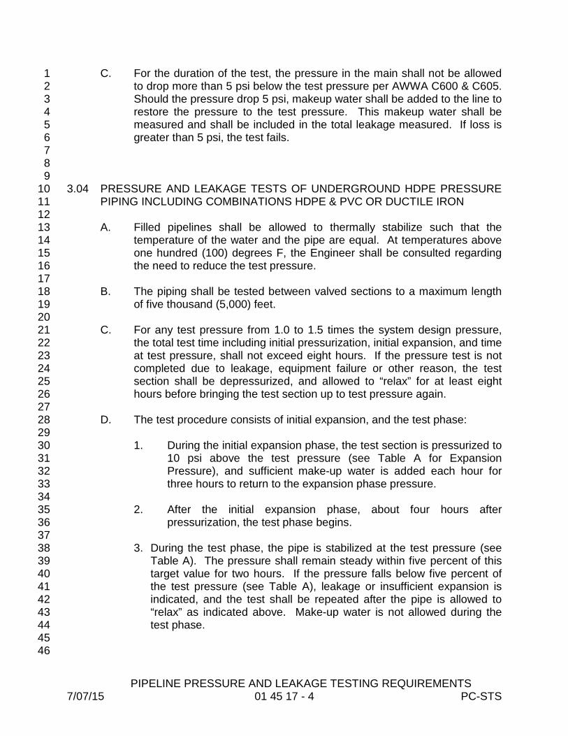
C. For the duration of the test, the pressure in the main shall not be allowed 1 to drop more than 5 psi below the test pressure per AWWA C600 & C605. 2 Should the pressure drop 5 psi, makeup water shall be added to the line to 3 restore the pressure to the test pressure. This makeup water shall be 4 measured and shall be included in the total leakage measured. If loss is 5 greater than 5 psi, the test fails. 6
7 8 9 3.04 PRESSURE AND LEAKAGE TESTS OF UNDERGROUND HDPE PRESSURE 10
PIPING INCLUDING COMBINATIONS HDPE & PVC OR DUCTILE IRON 11 12 A. Filled pipelines shall be allowed to thermally stabilize such that the 13
temperature of the water and the pipe are equal. At temperatures above 14 one hundred (100) degrees F, the Engineer shall be consulted regarding 15 the need to reduce the test pressure. 16
17 B. The piping shall be tested between valved sections to a maximum length 18
of five thousand (5,000) feet. 19 20 C. For any test pressure from 1.0 to 1.5 times the system design pressure, 21
the total test time including initial pressurization, initial expansion, and time 22 at test pressure, shall not exceed eight hours. If the pressure test is not 23 completed due to leakage, equipment failure or other reason, the test 24 section shall be depressurized, and allowed to “relax” for at least eight 25 hours before bringing the test section up to test pressure again. 26
27 D. The test procedure consists of initial expansion, and the test phase: 28
29 1. During the initial expansion phase, the test section is pressurized to 30
10 psi above the test pressure (see Table A for Expansion 31 Pressure), and sufficient make-up water is added each hour for 32 three hours to return to the expansion phase pressure. 33
34 2. After the initial expansion phase, about four hours after 35
pressurization, the test phase begins. 36 37
3. During the test phase, the pipe is stabilized at the test pressure (see 38 Table A). The pressure shall remain steady within five percent of this 39 target value for two hours. If the pressure falls below five percent of 40 the test pressure (see Table A), leakage or insufficient expansion is 41 indicated, and the test shall be repeated after the pipe is allowed to 42 “relax” as indicated above. Make-up water is not allowed during the 43 test phase. 44
45 46
PIPELINE PRESSURE AND LEAKAGE TESTING REQUIREMENTS 7/07/15 01 45 17 - 5 PC-STS
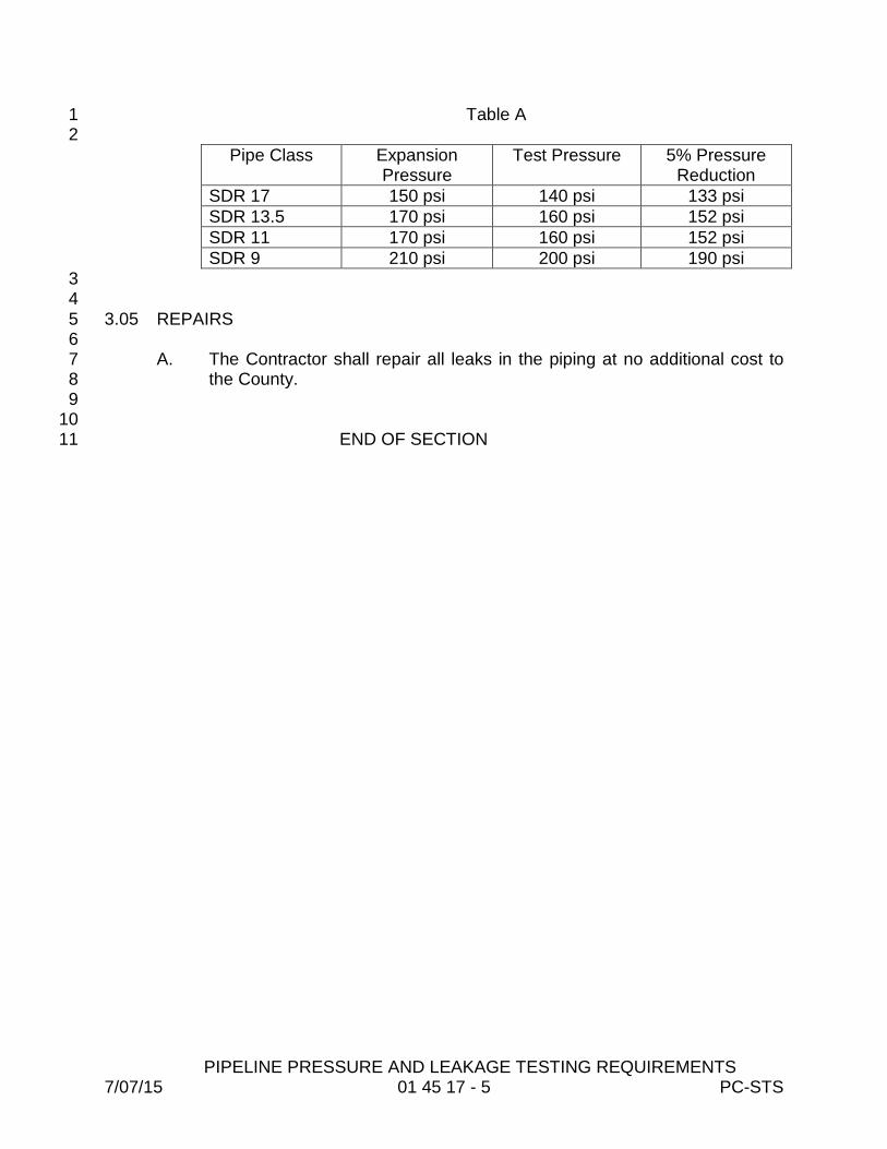
Table A 1 2
Pipe Class Expansion Pressure
Test Pressure 5% Pressure Reduction
SDR 17 150 psi 140 psi 133 psi SDR 13.5 170 psi 160 psi 152 psi SDR 11 170 psi 160 psi 152 psi SDR 9 210 psi 200 psi 190 psi 3 4
3.05 REPAIRS 5 6
A. The Contractor shall repair all leaks in the piping at no additional cost to 7 the County. 8
9 10
END OF SECTION 11

TRAFFIC REGULATION 7/07/15 01 55 26 - 1 PC-STS
SECTION 01 55 26 1 2
TRAFFIC REGULATION 3 4
PART 1 – GENERAL 5 6 1.01 WORK INCLUDED 7 8
A. This item will consist of providing, installing, moving, replacing, 9 maintaining, cleaning and removal upon completion of Work, all signs, 10 barricades, pavement markings, barriers, cones, lights, signals and other 11 devices necessary for the safe movement of all vehicular and pedestrian 12 traffic through and within the Project. 13
14 B. The Contractor shall arrange his work so that there will be as little 15
disruption of traffic as possible. 16 17
C. The Contractor shall have a Certified Worksite Traffic Supervisor in 18 accordance with the General Conditions. 19
20 1.02 REFERENCES 21 22
A. U.S. Department of Transportation (FHWA) Manual of Uniform Traffic 23 Control Devices as adopted by the Florida Department of Transportation 24 (latest edition). 25
26 B. Florida Department of Transportation Design Standards, latest edition. 27 28 C. Florida Department of Transportation Standard Specification for Road and 29
Bridge Construction, latest edition. 30 31
1.03 SUBMITTALS 32 33 A. The Contractor shall obtain approval from the City, County or State 34
Agency having jurisdiction over the road or highway for any road crossings 35 and detours required. 36
37 B. Maintenance of Traffic (MOT) plans, if provided in the Contract Drawings, 38
are considered a minimum requirement and it is the Contractor’s 39 responsibility to provide a safe traffic, pedestrian and working environment 40 in accordance with the governing regulations. Contractor shall adjust the 41 MOT plan as necessary to meet the field conditions at no additional cost 42 to the County. 43
44 C. If MOT plans are not provided in the Contract Drawings, a detailed traffic 45
control plan and MOT plan shall be developed and submitted by the 46 Contractor to such Agencies having jurisdiction over the road for their 47 approval, and said approval shall be obtained prior to commencing 48 construction. 49

TRAFFIC REGULATION 7/07/15 01 55 26 - 2 PC-STS
1 D. Any deviations from the Contract Drawings, or MOT plans specifically 2
developed by the Contractor, shall be submitted to the applicable 3 permitting entity for approval, and said approval shall be obtained, prior to 4 commencement of construction. If the alternative MOT plan is deemed 5 incomplete or unacceptable the Contractor will be required to submit a 6 revised plan. This process will repeat itself until the revised plan is 7 accepted by all parties. Contractor will not be granted or approved any 8 costs or delay resulting from the review process or field adjustments. 9
10 E. All traffic control plans shall be prepared by a Florida Certified Traffic 11
Planner. 12 13
PART 2 – PRODUCTS 14 15 2.01 INSTALLATION STANDARDS 16 17
A. All signs, barricades, pavement markings, traffic signals and channelizing 18 devices used to handle traffic shall be provided for and erected in 19 accordance with the FDOT Design Standards (latest edition) and to the 20 details indicated in the above referenced standards. Traffic signs shall be 21 high-intensity flat-surface reflective sheeting. 22
23 PART 3 – EXECUTION 24 25 3.01 GENERAL 26 27
A. In order that the Contractor may properly provide required traffic controls, 28 the Contractor shall notify the appropriate agencies a minimum of two 29 working days prior to any construction affecting traffic flow. 30
31 3.02 MAINTENANCE OF TRAFFIC LANE AND ROAD CLOSURES 32 33
A. The Contractor shall arrange his work so that there will be as little 34 disruption of traffic as possible. 35
36 B. The Contractor shall be approved by the City, County or State Agency 37
having jurisdiction over the road or highway for any road crossings and 38 detours required. A detailed traffic control plan shall be submitted by the 39 Contractor to such Agencies having jurisdiction over the road for their 40 approval at least three weeks prior to commencing construction. 41
42 C. In the event that a road closure is approved by the permitting Agency, the 43
Contractor will be responsible for any rerouting of traffic occasioned by the 44 closure and will provide all necessary barricades, signs, guards, lights, 45 etc. in accordance with the Agency's approval of such closure. 46
47 3.03 ACCESS TO PROPERTIES 48
TRAFFIC REGULATION 7/07/15 01 55 26 - 3 PC-STS
1 A. When construction activities necessitate the closing of a street to through-2
traffic, the Contractor shall notify all affected emergency services entities 3 of the closed road. If no other means of access is available, the 4 Contractor shall maintain, at all times, a 10-foot-wide lane adjacent to the 5 work area, free of construction equipment and obstructions, for the use of 6 emergency vehicles. 7
8 B. The Contractor shall provide continuous access to properties adjacent to 9
work areas. 10 11
3.04 LOCAL TRAFFIC 12 13
A. The roads shall be kept open to two-way traffic during construction, except 14 one lane traffic will be permitted provided experienced flag personnel are 15 used. Necessary barricades, safety vests and flags shall be used. No 16 residences or places of business will be isolated. Suitable access shall be 17 provided whenever construction interferes with the existing means of 18 access. 19
20 3.05 PEDESTRIAN TRAFFIC 21 22
A. The Contractor shall take precautions to ensure the safety of pedestrians 23 passing near work areas. This may entail the erection of a temporary 24 fence on the construction side of pedestrian passageways to delineate 25 out-of-bounds areas. The pedestrian passageways shall remain open and 26 clean of dirt and debris at all times unless pedestrian safety cannot be 27 assured, then the Contractor may close off the sidewalk(s) with signs and 28 fences and shall direct pedestrians to use other suitable routes. 29 Pedestrian passageways shall be cleared and swept in the vicinity of 30 construction. 31
32 B. The Contractor shall pay close attention to the issue of pedestrian safety. 33
The Contractor shall institute measures, including, but not limited to, 34 temporary surfaces and channeling devices, to ensure the safe passage 35 of pedestrians. 36
37 3.06 BUS STOPS 38 39
A. The Contractor shall take care to minimize disruption to existing bus stops. 40 If a bus stop cannot be preserved, then the Contractor shall make 41 provisions for its relocation. The Contractor shall be responsible for all 42 coordination regarding the temporary relocation of bus stops 43
44 END OF SECTION 45
46 47 48

CONTROL OF WORK 7/07/15 01 57 00 - 1 PC-STS
SECTION 01 57 00 1 2 CONTROL OF WORK 3 4 PART 1 - GENERAL 5 6 1.01 SCOPE OF WORK 7 8
A. The Work to be done consists of the furnishing of all labor, materials and 9 equipment, and the performance of all Work included in this Contract. 10 11
B. The Contractor shall furnish all labor, superintendence, materials, plant, 12 power, light, heat, fuel, water, tools, appliances, equipment, supplies and 13 other means of construction necessary or proper for performing and 14 completing the Work. He shall perform and complete the Work in the 15 manner best calculated to promote rapid construction consistent with safety 16 of life and property and to the satisfaction of the County, and in strict 17 accordance with the Contract Documents. The Contractor shall clean up the 18 Work and maintain it during and after construction, until accepted, and shall 19 do all Work and pay all costs incidental thereto. He shall repair or restore all 20 structures and property that may be damaged or disturbed during 21 performance of the 22
Work. 23 24 C. The Contractor shall supervise and direct the Work in accordance with 25
Pinellas County Utilities Standard Technical Specifications. 26 27 D. The cost of incidental work described in these Construction Specifications, 28
for which there are no specific Contract Items, shall be considered as part of 29 the general cost of doing the Work and shall be included in the prices for the 30 various Contract Pay Items. 31
32 E. The Contractor shall provide and maintain such modern plant, tools, and 33
equipment as may be necessary to perform in a satisfactory and acceptable 34 manner all the Work required by this Contract. Only equipment of 35 established reputation and proven efficiency shall be used. The Contractor 36 shall be solely responsible for the adequacy of his workmanship, materials 37 and equipment, prior approval of the County notwithstanding. 38
39 F. Public Utilities and Structures 40
41 1. Public utility installations and structures shall be understood to include 42
all poles, tracks, pipes, wires, conduits, house service connections, 43 vaults, manholes and all other appurtenances and facilities pertaining 44 thereto whether owned or controlled by the County, other governmental 45 bodies or privately owned by individuals, firms or corporations, used to 46 serve the public with transportation, traffic control, gas, electricity, 47

CONTROL OF WORK 7/07/15 01 57 00 - 2 PC-STS
telephone, sewerage, drainage, water or other public or private property 1 which may be affected by the Work shall be deemed included 2 hereunder. The Contractor shall protect all public utility installations and 3 structures from damage during the Work, except those specifically 4 designated to be removed or relocated. The Contractor shall so 5 arrange his operations as to avoid any damage to any buried public 6 utility installation or structure. All required protective devices and 7 construction shall be provided by the Contractor at his expense. All 8 existing public utilities damaged by the Contractor, which are shown on 9 the Plans or have been located in the field by the utility, shall be 10 repaired by the Contractor, at his expense. No separate payment shall 11 be made for such protection or repairs to public utility installations or 12 structures. 13
14 2. Public utility installations or structures owned or controlled by the 15
County or other governmental body, which are shown on the Plans to 16 be removed, relocated, replaced or rebuilt by the Contractor, shall be 17 considered as a part of the general cost of doing the Work and shall be 18 included in the prices Bid for the various contract items. No separate 19 payment shall be made therefor. 20
21 3. Where public utility installations or structures owned or controlled by the 22
County or other governmental body are encountered during the course 23 of the Work, and are not indicated on the Plans or in the Specifications, 24 and when, removal, relocation, replacement or rebuilding is necessary 25 to complete the Work under this Contract, such work shall be 26 accomplished by the utility having jurisdiction, or if required, by the 27 Contractor. 28
29 4. The Contractor shall give written notice to governmental utility 30
departments and other owners of public utilities of the locations of his 31 proposed construction operations, at least forty-eight (48) hours in 32 advance of breaking ground in any area or on any unit of the Work. 33 This can be accomplished by making the appropriate contact with the 34 "Underground Utility Notification Center for Excavators (Call 35 Sunshine)." 36
37 5. The maintenance, repair, removal, relocation or rebuilding of public 38
utility installations and structures, when accomplished by the Contractor 39 as herein provided, shall be done by methods approved by the utility 40 and the County. 41
42 G. The Contractor shall not enter upon private property for any reason without 43
securing prior permission from the property owner. 44 45

CONTROL OF WORK 7/07/15 01 57 00 - 3 PC-STS
H. During the progress of the Work the Contractor shall keep the work site free 1 from an accumulation of rubbish, waste materials or any type of debris 2 resulting from the construction. 3
4 1.02 DRAWINGS AND SPECIFICATIONS 5 6
A. The Contractor shall furnish each of the subcontractors, manufacturers, and 7 suppliers such copies of the Contract Documents as may be required for 8 their work. 9
10 1.03 MATERIALS AND EQUIPMENT 11 12
A. All transactions with the manufacturers or subcontractors shall be through 13 the Contractor. 14
15 B. All materials and equipment shall be new, unless otherwise provided. The 16
Contractor shall furnish satisfactory evidence as to the type and quality of 17 materials or equipment to be furnished and installed on this Project. 18
19 C. Materials of fabrication and construction to be furnished and permanently 20
installed in the Project shall be of the best quality. The workmanship of 21 construction, fit and finish on the Project shall be equal to the highest 22 standards of the industry. As indicated above, all materials and equipment 23 and/or components thereof shall be new and shall not have been in service 24 at any other installation. 25 26
D. The Contractor shall deliver materials in ample quantities to insure the most 27 speedy and uninterrupted progress of the Work so as to complete the Work 28 within the allotted time. The Contractor shall also coordinate deliveries in 29 order to avoid delay in, or impediment of, the progress of the work of any 30 related Contractor. The Contractor shall replace, at his own expense, all 31 such material(s) found to be damaged in shipment or handling or defective in 32 manufacture. The cost of the replacement material and labor of installation 33 for the replacement of previously installed material found to be defective prior 34 to the final acceptance of the work shall also be the responsibility of the 35 Contractor. 36
37 E. All materials and equipment to be incorporated into the Project shall be 38
loaded and unloaded by a method that will provide protection against 39 damage. Every precaution shall be taken to prevent damage or injury to the 40 equipment and material during transporting and handling. Proper and 41 suitable power equipment shall be used in the loading or unloading process. 42 Under no condition shall any items of equipment be dropped or rolled from a 43 truck or dragged over the ground after being unloaded. When a crane or 44 similar type equipment is used in loading or unloading, a suitable lifting sling 45 and hook shall be used. 46

CONTROL OF WORK 7/07/15 01 57 00 - 4 PC-STS
F. It will be the responsibility of the Contractor to store delivered materials or 1 equipment in a secure area. The Contractor will be responsible for any 2 damages resulting from vandalism or other reasons. Replacement of 3 materials or equipment lost, stolen, damaged or destroyed, due to careless 4 or improper storage, will be the Contractor's responsibility. All stored 5 materials shall be easily and readily accessible for inspection by the County’s 6 representative. 7
8 G. The Contractor shall, unless otherwise stated in the Contract Documents, 9
furnish with each type, kind or size of equipment, one complete set of 10 suitably marked high grade special tools and appliances which may be 11 needed to adjust, operate, maintain or repair the equipment. Such tools and 12 appliances shall be furnished in approved painted steel cases, properly 13 labeled and equipped with good grade cylinder locks and duplicate keys. 14
15 H. Each piece of equipment shall be provided with a substantial nameplate, 16
securely fastened in place and clearly inscribed with the manufacturer's 17 name, year of manufacture, serial number, weight and principal rating data. 18
19 I. The Contractor shall have on hand sufficient proper equipment and 20
machinery of ample capacity to facilitate the Work and to handle all 21 emergencies normally encountered in work of this character. 22
23 J. Equipment shall be erected in a neat and workmanlike manner on the 24
foundations at the locations and elevations shown on the Drawings. All 25 equipment shall be correctly aligned, leveled and adjusted for satisfactory 26 operation and shall be installed so that proper and necessary connections 27 can be made readily between the various units. 28
29 K. The Contractor shall furnish, install and protect all necessary anchor and 30
attachment bolts and all other appurtenances needed for the installation of 31 the devices included in the equipment specified.Stainless steel anchor bolts 32 shall be ample size and strength for the purpose intended. Substantial 33 templates and working drawings for installation shall be furnished. 34
35 L. The Contractor shall, at his own expense, furnish all materials and labor for, 36
and shall properly bed in non-shrink grout, each piece of equipment on its 37 supporting base that rests on masonry foundations. Grout shall completely 38 fill the space between the equipment base and the foundation. All metal 39 surfaces coming in contact with concrete or grout shall receive a coat of coal 40 tar epoxy. 41
42 M. Obtaining Materials From Pinellas County Utilities 43
44 1. Any material obtained from the Utilities Department shall be 45
thoroughly inspected by the Contractor so as to determine any 46
CONTROL OF WORK 7/07/15 01 57 00 - 5 PC-STS
defects, damage or unsoundness of the materials. Items accepted by 1 the Contractor shall be signed for by his authorized representative, 2 and the Contractor shall be responsible for such items from the time 3 he picks them up to the time they are installed and accepted by the 4 Utilities Department. 5
6 2. Upon acceptance of any material from Pinellas County Utilities, the 7
Contractor shall be responsible for loading the material at the storage 8 yard and unloading the material at the job site and for the safe 9 transportation of the material between those locations 10
11 1.04 INSPECTION AND TESTING 12 13
A. The Contractor shall be fully responsible for the proper operation of 14 equipment during tests and instruction periods and shall neither have, nor 15 make any claim for damage, which may occur to equipment prior to the time 16 when the County formally takes over the operation thereof. 17
18 B. When requested, the Contractor shall furnish authoritative evidence in the 19
form of Certificates of Manufacture that the materials to be used in the work 20 have been manufactured and tested in conformity with the Contract 21 Documents. These certificates shall be notarized and shall include copies of 22 the results of physical tests and chemical analyses, where necessary, that 23 have been made directly on the product or on similar products of the 24 manufacturer. 25
26 C. As soon as conditions permit, the Contractor shall furnish all labor, materials, 27
and instruments and shall make preliminary field tests. If the preliminary field 28 tests reveal that the system does not comply with the requirements of the 29 Contract Documents, the Contractor shall, prior to the acceptance tests, 30 make all changes, adjustments and replacement required. 31
32 D. Upon completion of the Work and prior to final payment, all equipment and 33
piping shall be subjected to acceptance tests as specified or required to 34 prove compliance with the Contract Documents. 35
36 E. The Contractor shall furnish labor, fuel, energy, and all other materials, 37
equipment and instruments necessary for all acceptance tests, at no 38 additional cost. The Supplier shall assist in the final field tests as applicable. 39
40 F. Any defects in the materials and equipment or their failure to meet the tests, 41
guarantee or requirements of the Contract Documents shall be promptly 42 corrected by the Contractor. If the Contractor fails to make these corrections 43 or if the improved materials and equipment, when tested, shall again fail to 44 meet the guarantees or specified requirements, the materials and equipment 45 may be rejected and removed from the site at the Contractor’s expense. 46

CONTROL OF WORK 7/07/15 01 57 00 - 6 PC-STS
1.05 FIRST AID 1 2
A. The Contractor shall keep upon the site, at each location where work is in 3 progress, a completely equipped first aid kit and shall provide ready access 4 thereto at all times when people are employed on the work. 5
6 1.06 ADJACENT STRUCTURES AND PROPERTY 7 8
A. The Contractor shall also be entirely responsible and liable for all damage or 9 injury as a result of his operations to all other adjacent public and private 10 property, structures of any kind and appurtenances thereto met with during 11 the progress of the Work. The cost of protection, replacement in their 12 original locations and conditions or payment of damages for injuries to such 13 adjacent public and private property and structures affected by the Work, 14 whether or not shown on the Drawings or specified, shall be included in the 15 various Contract Items and no separate payments will be made therefore. 16
17 B. Contractor is expressly advised that the protection of buildings structures, 18
tunnels, tanks, pipelines, etc. and related work adjacent to and in the vicinity 19 of his operations, wherever they may be, is solely his responsibility. 20 Conditional inspection of buildings or structures in the immediate vicinity of 21 the Project, which may reasonably be expected to be affected by the Work, 22 shall be performed by and be the responsibility of the Contractor. 23
24 C. Contractor shall, before starting operations, make an examination of the 25
interior and exterior of the adjacent structures, buildings, facilities, etc., and 26 record by noted, measurements, photographs, etc., conditions which might 27 be aggravated by open excavation and construction. Repairs or replacement 28 of all conditions disturbed by the construction shall be made to the 29 satisfaction of the County. This does not preclude conforming to the 30 requirements of the Insurance Underwriters. 31
32 1.07 PROTECTION, REMOVAL AND REPLACEMENT OF TREES AND SHRUBS 33 34
A. The Contractor shall comply with all local tree ordinances. When, in the 35 opinion of the Engineer, trees or shrubs can be protected in place, the 36 Contractor shall endeavor to protect the trees or shrubs as necessary. 37 When, in the opinion of the Engineer, trees must be removed to permit 38 construction, the Contractor shall consider the price for removing, cutting, 39 trimming, replacing trees and shrubs incidental to the laying of pipe and no 40 additional payment shall be made unless specifically called for in the 41 Contract Documents. 42
43 B. The Contractor is responsible for acquiring necessary permits and replacing 44
trees as required by local ordinances and the Pinellas County Department of 45 Environmental Management. The Contractor shall provide the services of an 46 approved tree specialist when it is necessary to trim or cut a branch from a 47
CONTROL OF WORK 7/07/15 01 57 00 - 7 PC-STS
tree. 1 1.08 PROTECTION OF WORK AND PUBLIC 2 3
A. Barriers and Lights 4 5
1. The Contractor shall provide and maintain proper and adequate 6 barricades, construction signs, torches, flashers, construction tapes, 7 flagmen, guards or other traffic control devices as may be necessary 8 to provide the required safety and protection to the public at and 9 around the perimeter of the construction areas. The Contractor shall 10 provide suitable barricades, red lights, "danger" or "caution" or "street 11 closed" signs and watchmen at all places where the work causes 12 obstructions to the normal traffic or constitutes in any way a hazard to 13 the public. The Contractor shall comply with all City, County or State 14 regulations. 15
16 B. Smoke Prevention 17
18 1. A strict compliance with ordinances regulating the production of 19
emission of smoke will be required. No open fires will be permitted. 20 21
C. Noise 22 23
1. The Contractor shall eliminate noise to as great an extent as 24 practicable at all times. Air compressing plants shall be equipped with 25 silencers and the exhaust of all gasoline, diesel, motors or other 26 power equipment shall be provided with mufflers. The Contractor 27 shall strictly observe all local regulations and ordinances covering 28 noise control. 29
30 2. If mufflers and silencers cannot achieve the necessary noise 31
reduction, other noise abatement procedures shall be instituted by the 32 Contractor, such as installation of 3/4-inch plywood baffles positioned 33 to break off line-of-sight from the noise source to affected residences 34 and/or commercial structures. 35
36 D. Access to Public Services 37
38 1. Neither the materials excavated nor the materials or plant used in the 39
construction of the work shall be placed to prevent free access to all 40 fire hydrants, valves or manholes. 41
42 E. Dust Prevention 43
44

CONTROL OF WORK 7/07/15 01 57 00 - 8 PC-STS
1. It is the responsibility of the Contractor to control all dust problems 1 that may occur during the construction, with required watering.. Dust 2 control will be required seven days a week. 3
F. Safety 4 5
1. The Contractor will be responsible for initiating, maintaining and 6 supervising all safety precautions and programs in connection with the 7 Project. He will take all necessary precautions for the safety of and 8 will provide the necessary protection to prevent damage, injury or loss 9 to all employees on the Project and other persons who may be 10 affected thereby, all the work and all material or equipment to be 11 incorporated therein, whether in storage on or off the site. 12
13 2. The Contractor shall comply with all applicable laws, ordinances, 14
rules, regulations and orders of any public body having jurisdiction. 15 He will erect and maintain, as required by the conditions and progress 16 of the work, all necessary safeguards for safety and protection. He 17 will notify owners of adjacent utilities when prosecution of the work 18 may affect them. The Contractor will remedy all damage, injury or loss 19 of any property caused, directly or indirectly, in whole or in part, by the 20 Contractor, any subcontractor or anyone directly or indirectly 21 employed by any one of them or anyone for whose acts of any of 22 them be liable. 23
24 3. In emergencies affecting the safety of persons or the work or property 25
at the site or adjacent thereto, the Contractor, without special 26 instruction or authorization from the Engineer or Pinellas County 27 Inspector, shall act to prevent threatened damage, injury or loss. He 28 will give Pinellas County prompt written notice of any significant 29 change in the Work or deviations from the approved plans required 30 relating to the emergency. 31
32 4. It is the Contractor's responsibility to comply with the Occupational 33
Safety and Health Administration safety standards. 34 35 5. Standard 29 CFR 1926.650, Subpart P, trench safety standards are in 36
effect during the period of construction of the Project. 37 38
6. The Contractor shall comply with all Occupational Safety and Health 39 Association (OSHA) requirements for work in confined spaces. This 40 shall include, but not be limited to, provision of a force-ventilated 41 working space. 42
43 7. Hard hats shall be worn at the work site by all personnel as required 44
by all local, state and federal guidelines. The Engineer is authorized 45 to halt the work if this requirement is not met. 46

CONTROL OF WORK 7/07/15 01 57 00 - 9 PC-STS
1 2 3 G. Pollution Control 4
5 1. The Contractor shall provide for adequate protection against polluting 6
any private or public lands, streams, ponds, lakes, sanitary or storm 7 drainage systems, etc., by the disposal of surplus materials in the 8 form of solids or liquids or any other deleterious materials (fuels, oils, 9 bitumens, etc.) 10
11 1.09 CUTTING AND PATCHING 12 13
A. The Contractor shall do all cutting, fitting or patching of his portion of the 14 work that may be required to make the several parts thereof join and 15 coordinate in accordance with the Drawings and Specifications. The work 16 must be done by competent workmen skilled in the trade required. 17
18 1.10 CLEANING 19 20
A. During construction of the Work, the Contractor shall, at all times, keep the 21 site of the work and adjacent premises as free from material, debris and 22 rubbish as is practicable and shall remove the same from any portion of the 23 site. 24
25 B. At the conclusion of the Work, all erection plant, tools, temporary structures 26
and materials belonging to the Contractor shall be promptly taken away, and 27 he shall remove and promptly dispose of all water, dirt, rubbish or any other 28 foreign substances. 29
30 C. The Contractor shall thoroughly clean all equipment and materials installed 31
by him and shall deliver such materials and equipment undamaged in a 32 bright, clean, polished and new operating condition. 33
34 1.11 EROSION CONTROL, WETLANDS AND STORM SEWERS 35 36 A. Protection Against Siltation and Bank Erosion 37 38 1. The Contractor shall arrange his operations to minimize siltation and 39
bank erosion on construction sites and on existing or proposed water 40 courses, drainage ditches, wetlands and other areas of concern. 41
42 2. The Contractor, at his own expense, shall remove any siltation deposits 43
and correct any erosion problems, which result from his construction 44 operations. 45
3. The Contractor shall be solely responsible for any fines resulting from 46
CONTROL OF WORK 7/07/15 01 57 00 - 10 PC-STS
the encroachment of any environmentally protected areas. 1 2 3 B. Protection of Wetland Areas 4 5 1. The Contractor shall properly dispose of all surplus material, including 6
soil, in accordance with Local, State and Federal regulations. Under no 7 circumstances shall surplus material be disposed of in wetland areas as 8 defined by the Florida Department of Environmental Protection, 9 Southwest Florida Water Management District, U.S. Army Corps of 10 Engineers, etc. 11
12 C. Sanitary & Storm Sewer Systems 13 14 1. The Contractor shall be entirely responsible for the satisfactory 15
replacement of storm sewer and installation of sanitary sewer systems 16 in substantial conformance to the approved Drawings. It is strongly 17 recommended that no roadway base or paving be constructed until the 18 Contractor has performed televising of these lines to his and the 19 County's satisfaction, and all storm sewer and sanitary sewer invert 20 grades are verified in the field. The lamping of lines and verification of 21 elevations in no way absolves the Contractor from any of his 22 contractual obligations. 23
24 1.12 RESTORATION OF PROPERTY 25 26
A. Responsibility. All damage as a result of construction work done to existing 27 structures, wetland areas, roadway pavement, driveways, other paved areas, 28 fences, utilities, traffic control devices and any other obstruction not 29 specifically named herein, shall be repaired, restored or replaced by the 30 Contractor unless otherwise specified. 31
32 B. Temporary Repairs. All damage named in Paragraph A above shall be at 33
least temporarily repaired, restored or replaced immediately following 34 construction efforts at that location. Temporary restoration shall mean 35 putting the affected area back into a safe, usable condition. In no case shall 36 trenches remain open over night within a street right-of-way unless specific 37 approval is granted by the County. 38
39 C. Permanent Repairs. All damage named in Paragraph A above shall be 40
permanently repaired, restored, or replaced before final completion. 41 Permanent repairs shall be accomplished in a professional workmanship-like 42 manner. 43
44 D. In all areas disturbed by the work, the Contractor shall grade and restore the 45
site to a condition as good or better than existed before construction. 46
CONTROL OF WORK 7/07/15 01 57 00 - 11 PC-STS
Sodded areas shall be sodded with sod matching the existing adjacent sod. 1 Any drives, walks, pavements, structures, survey monuments, property 2 corner markers, trees, shrubs, or any other public or private property 3 damaged or destroyed by the work shall be restored or replaced at the 4 Contractor's expense. 5
6 1.13 MAINTENANCE OF TRAFFIC 7 8 A. Maintenance of Traffic shall be in accordance with Specification 01 55 26, 9
Traffic Control. 10 11 1.14 MATERIALS 12 13
A. All materials installed in the County’s easements or rights-of-way shall be 14 approved in the County’s Materials Specification Manual regardless of whether 15 these facilities are to be owned by the County or are to be privately owned. 16
17
18
19 PART 2 – PRODUCTS (Not Used) 20 21 PART 3 – EXECUTION (Not Used) 22
23 24
END OF SECTION 25

EROSION AND SEDIMENTATION CONTROL 7/07/15 01 57 13 - 1 PC-STS
SECTION 01 57 13 1 2
EROSION AND SEDIMENTATION CONTROL 3 4 5 6 PART 1 - GENERAL 7 8 1.01 WORK INCLUDED 9 10
A. Take every reasonable precaution throughout construction to prevent the 11 erosion of soil and the sedimentation of streams, bays, storm systems or 12 other water impoundments, ground surfaces, or other property as required 13 by State and Local regulations. 14
15 1.02 RELATED WORK 16 17
A. Provide protective covering for disturbed areas upon suspension or 18 completion of land-disturbing activities. Permanent vegetation shall be 19 established at the earliest practicable time. Temporary and permanent 20 erosion control measures shall be coordinated to assure economical, 21 effective, and continuous erosion and siltation control throughout the 22 construction and post construction period. 23
24 1.03 REGULATORY REQUIREMENTS 25 26
A. Prevent damage to properties outside the construction limits from siltation 27 due to construction of the project. Assume all responsibilities to the 28 affected property owners for correction of damages, which may occur. 29 Erosion control measures shall be performed conforming to the 30 requirements of, and in accordance with plans approved by applicable 31 state and local agencies and as per the erosion control portion of the 32 construction drawings and these specifications. The Contractor shall not 33 allow mud and debris to accumulate in the streets. Should the Contractor 34 pump water from trenches during construction, appropriate siltation 35 preventative measures shall be taken prior to discharge of pumped water 36 into any storm drain or stream. The Contractor shall dispose of the water 37 without causing a nuisance, property damage and in compliance with the 38 National Pollution Discharge Elimination System (NPDES) and all 39 applicable jurisdictions. 40
41 PART 2 - PRODUCTS 42 43 2.01 GENERAL 44 45
A. Open mesh biodegradable mulching cloth. 46

EROSION AND SEDIMENTATION CONTROL 7/07/15 01 57 13 - 2 PC-STS
1 B. Fertilizer shall be 10-10-10 grade or equivalent. 2 3 C. Lime shall be Dolomitic Agricultural Ground limestone, per FDOT Section 4
982. 5 6
D. Provide permanent grass seed in accordance with Section 32 92 01. 7 8
E. Provide temporary grass seed in accordance with Section 32 92 01. 9 10
F. Silt fence shall consist of non-biodegradable filter fabric (Trevira, Mirafi, 11 etc.), per FDOT Section 985, wired to galvanized wire mesh fencing and 12 supported by wood or metal posts. 13
14 G. Floating turbidity barriers per FDOT Section 985 and FDOT Standard 15
Index 103. 16 17 H. Staked turbidity barriers 18 19 I. Rock bags 20
21 J. Erosion Stone: FDOT Section 530 22
1. Sand-Cement Riprap 23 2. Concrete Block 24 3. Rubble 20 to 300 pounds each 25
26 K. Filter Fabric for placement under Riprap shall meet the requirements 27
FDOT Section 985. 28 29 L. Baled hay or straw in accordance with FDOT Section 104. 30 31 M. Drain pipe with sock (sedimentation control) shall be used to prevent and 32
control soil erosion runoff and intrusion into stormwater drainage systems. 33 34
1. Drain sock products such as “ADSSock” or approved equal. 35 2. Sock material shall be on ultra-porous filter (synthetic wrap 36
material) fitted snuggly over pipe. Material shall be 100 percent 37 knitted polyester (or approved equal), equivalent opening size of 30 38 to 40, burst strength of 100-135 (ASTM D 3786), fiber size of 100-39 200 denier filament, 2.5 to 3.5 ounces per square yard (ASTM D 40 3776). 41
3. Approval of material is required by County prior to use. 42 4. Drain pipe with sock shall span the entire opening of the inlet. 43
44 45 46
EROSION AND SEDIMENTATION CONTROL 7/07/15 01 57 13 - 3 PC-STS
PART 3 - EXECUTION 1 2 3.01 CLEARING 3 4
A. Clearing and grubbing shall be scheduled and performed in such a 5 manner that subsequent grading operation and erosion control practices 6 can follow immediately thereafter. Excavation, borrow, and embankment 7 operations will be conducted as a continuous operation. All construction 8 areas not otherwise protected shall be planted with permanent vegetative 9 cover within 30 working days after completion of active construction. 10
11 3.02 STABILIZING 12 13
A. The angle for graded slopes and fills shall be no greater than the angle, 14 which can be retained by vegetative cover or other adequate erosion 15 control devices or structures. All disturbed areas outside of embankment 16 left exposed will, within 30 working days of completion of any phase of 17 grading, be planted or otherwise provided with either temporary or 18 permanent ground cover, devices, or structures sufficient to restrain 19 erosion. 20
21 3.03 REGULATORY REQUIREMENTS 22 23
A. Whenever land disturbing activity is undertaken on a tract, a ground cover 24 sufficient to restrain erosion must be planted or other wise provided within 25 30 working days on that portion of the tract upon which further active 26 construction is to be undertaken. 27
28 B. If any earthwork is to be suspended for any reason whatsoever for longer 29
than 30 calendar days, the areas involved shall be seeded with vegetative 30 cover or otherwise protected against excessive erosion during the 31 suspension period. Suspension of work in any area of operation does not 32 relieve the Contractor of the responsibility for the control of erosion in that 33 area. 34
35 PART 4 - CONSTRUCTION PHASE 36 37 4.01 PRACTICES 38 39
A. Avoid dumping soil or sediment into any stream bed or watercourse. 40 41
B. Maintain an undisturbed vegetative buffer where possible between a 42 natural watercourse and trenching and grading operations. 43
44 C. Avoid equipment crossings of streams, creeks, and ditches where 45
practicable.46
EROSION AND SEDIMENTATION CONTROL 7/07/15 01 57 13 - 4 PC-STS
1 PART 5 - SEDIMENT CONTROL FEATURES 2 3 5.01 GENERAL 4 5
A. All devices (silt fences, retention areas, etc.), for sediment control shall be 6 constructed at the locations indicated prior to beginning excavation on the 7 site. All devices shall be properly maintained in place until a structure or 8 paving makes the device unnecessary or until directed to permanently 9 remove the device. 10
11 5.02 DESIGN APPLICATIONS 12 13
A. Mulch shall be used for temporary stabilization of areas subject to 14 excessive erosion, and for protection of seed beds after planting where 15 required. 16
17 B. Filter Fabric, drain pipe with sock, or other approved methods shall be 18
placed and secured over the grates of each existing inlet, grating or storm 19 pipe opening near the area of excavation to prevent silt and debris from 20 entering the storm systems. 21
C. Silt fences, hay bales and floating turbidity barriers shall be used as 22 shown on the plans or as directed by the Project Representative to restrict 23 movement of sediment from the site. 24
25 D. Establish vegetative cover on all unpaved areas disturbed by the work. 26
27 1. Preparation of Seedbed. Areas to be seeded shall be scarified a 28
depth of four inches until a firm, well pulverized, uniform seedbed is 29 prepared. Fertilizer shall be applied during the scarification process 30 in accordance with the following rates. 31 a. Fertilizer - 10 to 15 pounds per 1,000 square feet 32
2. Seeding. Disturbed areas along embankments shall be 33 permanently seeded with mix specified in Section 32-92-01. 34
35 3. Mulch all areas immediately after seeding. Mulch shall be applied 36
and anchored as specified herein before. 37 38 5.03 MAINTENANCE 39 40
A. Maintain all temporary and permanent erosion control measures in 41 functioning order. Temporary structures shall be maintained until such 42 time as vegetation is firmly established and grassed areas shall be 43 maintained until completion of the project. Areas which fail to show a 44 suitable stand of grass or which are damaged by erosion shall be 45 immediately repaired. No additional payment will be made to the 46
EROSION AND SEDIMENTATION CONTROL 7/07/15 01 57 13 - 5 PC-STS
Contractor for the re-establishment of erosion control devices, which may 1 become damaged, destroyed, or otherwise rendered unsuitable for their 2 intended function during the construction of the Project. 3
4 B. Remove all silt, sediment and debris buildup on a regular basis to 5
maintain functioning storm systems and erosion control devices. 6 7 5.04 REMOVAL OF SEDIMENT CONTROL DEVICES 8 9
A. Near completion of the project, when directed by the County’s's agent, the 10 Contractor shall dismantle and remove the temporary devices used for 11 sediment control during construction. All erosion control devices in 12 seeded areas shall be left in place until the grass is established. Seed 13 areas around devices and mulch after removing or filling temporary 14 control devices. Cleanup all areas. 15
16 END OF SECTION 17
PROJECT IDENTIFICATION SIGNS 8/24/15 01 58 01 - 1 PC-STS
SECTION 01 58 01 1 2
PROJECT IDENTIFICATION SIGNS 3 4
PART 1 - GENERAL 5 6 1.01 REQUIREMENTS INCLUDED 7 8
A. Furnish, install and maintain project identification sign on Pinellas County 9 Projects. 10
11 B. Remove sign on completion of construction. 12
13 1.02 PROJECT IDENTIFICATION SIGNS 14 15
A. Signs shall be not less than thirty-two (32) square feet in area, with 16 painted graphic content to include the following and as shown on the 17 following page: 18
19 1. Title of Project 20 2. Name of Owner 21 3. Names and titles of authorities as directed by County 22 4. Names and title of: 23
a. Engineer 24 b. Professional Consultants 25
5 Prime Contractor 26 6. Major subcontractors 27
7. Project Cost 28 8. Pinellas County Web Page 29 9. County logo 30 10. Other logos subject to the requirements of the Project. 31
32 B. Graphic design, style of lettering and colors: As approved by the 33
Engineer, subject to the approval of the County. 34 35 C. Erect on the site at a lighted location of high public visibility, as approved 36
by the Engineer and the County. 37 38
1.03 QUALITY ASSURANCE 39 40
A. Sign Painter: Professional experience in type of work required. 41 42
B. Finishes, Painting: Adequate to resist weathering and fading for 43 scheduled construction period. 44
45 46

PROJECT IDENTIFICATION SIGNS 8/24/15 01 58 01 - 2 PC-STS
1 PART 2 - PRODUCTS 2 3 2.01 SIGN MATERIALS 4 5
A. Structure and Framing: May be new or used, wood or metal, in sound 6 condition, structurally adequate to work and suitable for specified finish. 7
8 B. Sign Surfaces: Exterior softwood plywood with medium density overlay, 9
standard large sizes to minimize joints. 10 11
1. Thickness: As required by standards to span framing members, to 12 provide even, smooth surface without waves or buckles. 13
14 C. Rough Hardware: Galvanized. 15
16 D. Paint: Exterior quality, as specified below. 17
18 1. Wood 19
20 a. Surface Preparation: Sand smooth, seal knots with white 21
shellac (fill holes with vinyl putty after prime). 22 23

PROJECT IDENTIFICATION SIGNS 8/24/15 01 58 01 - 3 PC-STS
b. Prime: Painted trim and siding - white pigmented non-1 penetrating alkyd based primer appled at the rate of 3.0 mils 2 dry film thickness. 3
4 c. Finish: Painted trim and face - apply two coats semi-gloss 5
modified acrylic latex applied at a rate of at least 2.0 mils dry 6 film thickness, per coat. 7
8 2. Steel 9
10 a. Surface Preparation: Commercial blast according to the 11
Steel Structures Painting Council Specifications SP-6. 12 13 b. Prime: One coat of a combination of lead chromate rust 14
inhibitive and synthetic pigmented alkyd resins, minimum 1.5 15 mils dry film thickness. If shop coat is damaged, reprime 16 base areas in field. 17
18 c. Finish: Two coats of semi-gloss medium to long oil alkyd 19
resin coating, 1.5 mils dry film thickness per coat. 20 21
3. Use Bulletin colors for graphics. 22 23 PART 3 - EXECUTION 24 25 3.01 PROJECT IDENTIFICATION SIGN 26 27
A. Paint exposed surfaces of supports, framing and surface material; one 28 coat of primer and one coat of exterior paint. 29
30 B. Paint graphics in styles, sizes and colors selected. 31
32 3.02 MAINTENANCE 33 34
A. Maintain signs and supports in a neat, clean condition; repair damages to 35 structures, framing or sign. 36
37 3.03 REMOVAL 38 39
A. Remove signs, framings, supports and foundations at completion of 40 Project. 41
42 43
END OF SECTION 44
PROJECT RECORD DOCUMENTS 7/07/15 01 78 39 - 1 PC-STS
SECTION 01 78 39 1 2
PROJECT RECORD DOCUMENTS 3 4 5 PART 1 – GENERAL 6 7 1.01 REQUIREMENTS INCLUDED 8 9
A. Contractor shall maintain at the site one record copy of: 10 11
1. Drawings. 12 2. Specifications. 13 3. Addenda. 14 4. Change Orders and other modifications to the Contract. 15 5. Engineer's field orders or written instructions. 16 6. Approved shop drawings, working drawings and samples. 17 7. Field test records. 18 8. Construction photographs. 19 9. Detailed Progress Schedule. 20 21
1.02 MAINTENANCE OF DOCUMENTS AND SAMPLES 22 23
A. Store documents and samples in Contractor's field office apart from 24 documents used for construction. 25
26 B. File documents and samples in accordance with CSI format. 27
28 C. Maintain documents in a clean, dry, legible, condition and in good order. 29
Do not use record documents for construction purposes. 30 31
D. Make documents and samples available at all times for review by the 32 Engineer and County. 33
34 E. As a prerequisite for monthly progress payments, the Contractor is to 35
exhibit the currently updated “record documents” for review by the 36 Engineer. 37
38 1.03 RECORDING 39 40
A. Label each document "PROJECT RECORD" in neat large printed letters. 41 42 B. Record information concurrently with construction progress. Do not 43
conceal any work until required information is recorded. 44 45
C. Drawings; Legibly mark to record actual construction: 46
PROJECT RECORD DOCUMENTS 7/07/15 01 78 39 - 2 PC-STS
1. Elevations of various structure elements in relation to grade. 1 2. All underground piping with elevations and dimensions. Changes in 2
piping location. Horizontal and vertical locations of underground 3 utilities and appurtenances, referenced to permanent surface 4 improvements. Actual installed pipe material, class, etc. 5
3. Location of internal utilities and appurtenances concealed in the 6 construction, referenced to visible and accessible features of the 7 structure. 8
4. Field changes of dimension and detail. 9 5. Changes made by Field Order or by Change Order. 10 6. Details not on original Contract Drawings. 11 7. Equipment and piping relocations. 12 8. Intersection details: At least three ties to every valve and fitting, 13
blowoff, fire hydrant and air release. 14 9. Services based on distance from main line pipe and property lines. 15 10. Backflow preventer assemblies locations, with ties to physical 16
features. 17 18 D. All horizontal locations, if not in the right-of-way, must relate to easement. 19 20 E. All elevations shall be in feet and tenths, referenced to NAVD 1988. 21 22 F. Specifications and Addenda; Legibly mark each Section to record: 23 24 1. Manufacturer, trade name, catalog number and supplier of each 25
product and item of equipment actually installed. 26 2. Changes made by Field Order or by Change Order. 27
28 1.04 SPECIAL REQUIREMENTS FOR MAIN REPAIRS 29 30 A. The Contractor will not be required to furnish as-built drawings for main 31
repairs, but shall be required to furnish a complete "bill of materials" used at 32 each repair, if requested by the County. 33
34 1.05 SPECIAL REQUIREMENTS FOR WATER MAINS, RECLAIMED WATER 35
MAINS AND FORCE MAINS 36 37
A. In addition to that specified above, the following information shall be 38 provided on the Record Drawings: 39
40 1. Location (vertical and any horizontal) at intervals not to exceed two 41
hundred (200) feet and at all locations where the direction changes 42 by more than ten (10) degrees. 43
2. Pipe size and material. 44 45 46

PROJECT RECORD DOCUMENTS 7/07/15 01 78 39 - 3 PC-STS
3. Air release manhole (rim and bottom elevation and horizontal 1 location) i.e. ties to back of curb and nearest property corner or 2 permanent control point. 3
4. Detailed location of valves (horizontal), i.e., ties to back of curb 4 and nearest property corner or permanent control point. 5
5. Service connection locations for each designated meter. 6 7 B. All top of pipe elevations shall be accompanied by a finished grade 8
elevation at the same location. 9 10 C. Horizontal location of the pipe shall be defined using ties to back of curb 11
and nearest property corner, property line or permanent control point. 12 13 D. Should supplemental information be compiled or be available related to 14
the “As-Built” condition of the Project, the Contractor shall provide that 15 information, along with the “As-Built Record Drawing” documentation 16 outlined above, which is required under the terms of the contract. Such 17 supplemental information may include but not be limited to: 18
19 1. Length of pipe between fittings with depth every one hundred (100) 20
feet. 21 2. Elevation of top of pipe at grade changes. 22 3. Manufacturer of pipe. 23 4. Manufacturer, number of turns to open and depth of valves 24 5. Define location of transition point between differing pipe materials 25 6. Flow capacity of fire hydrants if such field information was obtained 26
during construction. 27 28 1.06 SPECIAL REQUIREMENTS FOR GRAVITY SEWER 29 30
A. In addition to that specified above, the following information shall be 31 provided on the Record Drawings: 32
33 1. Manhole rim and invert elevations (include pipe inverts). 34 2. Manhole horizontal location (i.e. ties to back of curb and nearest 35
property corner or permanent control point.) 36 3 Service laterals located from nearest down stream manhole 37
(indicate any laterals out of manholes). 38 4. Distance between manholes. 39 5. Size and material of all pipe. 40
41 1.07 SPECIAL REQUIREMENTS FOR WASTEWATER PUMP STATIONS 42 43
A. In addition to that specified above, the following information shall be 44 provided on the Record Drawings: 45
46

PROJECT RECORD DOCUMENTS 7/07/15 01 78 39 - 4 PC-STS
1. Location ties to back of curb and nearest property corner or 1 permanent control point. 2
2. Wet well invert elevations. 3 3. Pipe invert elevations. 4 4. Valve vault inverts. 5 5. Top of slab elevations. 6 6. "As Built" elevations of all construction elevations shown on the 7
Drawings. 8 9
1.08 SUBMITTAL 10 11
A. At Final Completion Date, deliver Record Documents to the Engineer. 12 13 B. Provide certified Record Drawings in electronic format (AutoCAD r14 or 14
later version) meeting Pinellas County Standards and one hardcopy 15 signed and sealed by a Florida registered surveyor and mapper. 16
17 C. Accompany submittal with transmittal letter in duplicate, containing: 18
19 1. Date. 20 2. Project title and number. 21 3. Contractor's name and address. 22 4. Title and number of each Record Document. 23 5. Signature of Contractor or his authorized representative. 24
25 PART 2 – PRODUCTS (Not Used) 26 27 PART 3 – EXECUTION (Not Used) 28
END OF SECTION 29

CONCRETE MATERIALS 7/07/15 03 10 01 - 1 PC-STS
SECTION 03 10 01 1 2
CONCRETE MATERIALS 3 4 5 PART 1 - GENERAL 6 7 1.01 SCOPE OF WORK 8 9
A. The work shall include the furnishing of all materials, equipment and labor 10 required to construct all concrete work shown on the Drawings, or incidental to 11 the proper execution of the work. 12
13 1.02 RELATED SECTIONS 14 15
A. Section 32 13 01- Concrete Sidewalks, Driveways, and Gutters 16 17 1.03 DESIGN MIX 18 19
A. Prior to placing any concrete, the Contractor shall submit for the Engineer's 20 approval, a design mix, calculated by a recognized testing laboratory, and using 21 the approved aggregates to produce a workable mix of the desired strength, 22 together with certified copies of seven day and twenty-eight (28) day tests of 23 cylinders taken from concrete made according to the design mix. The mixes 24 shall be designed to secure concrete having a minimum compressive strength at 25 age twenty-eight (28) days as shown on the Plans or covered in other sections of 26 these Specifications. 27
28 PART 2 - PRODUCTS 29 30 2.01 CEMENT 31 32
A. Portland cement shall conform to the latest revision of Federal and/or ASTM 33 Specifications enumerated below: 34
35 1. For general concrete construction, ASTM designation C-150, Type I or 36
Type II, or Federal Specifications SS-C-192, Type I or II. 37 38 2. For construction of sewage treatment plant and pump station structures 39
Type II cement shall be used. 40 41 3. Slag cement shall conform to ASTM designation C-465. 42 43 4. Slag cement may be used in the maximum ratio of one part of slag 44
cement by weight to six parts of total cement by weight, if approval by the 45 Engineer, is obtained prior to use. 46

CONCRETE MATERIALS 7/07/15 03 10 01 - 2 PC-STS
B. Concrete Bag Mix 1 2 1. Quickete 5000 High Early Strength Concrete Mix #1007 or Engineer 3
approved equal. 4 5 2. Use of bag mix is strictly limited to non-structural use and Engineer 6
designated locations only. 7 8 3. The Contractor is required to strictly adhere to the mixing and installation 9
instructions set forth by the manufacturer. 10 11 4. Testing to be performed at Engineers discretion. Concrete not meeting 12
design strength or not properly installed per the manufacturer is subject to 13 removal and replacement at no additional cost to the County. 14
15 2.02 FINE AGGREGATE 16
17 A. Fine aggregate shall be clean, hard, strong, durable uncoated particles of natural 18
sand known as Lake Wales, Interlachen or approved equal. The source, 19 composition, quality and gradation of the fine aggregate shall be subject to the 20 approval of the Engineer. Samples of the sand shall be furnished, together with 21 certified copies of the gradation and analysis from a recognized testing 22 laboratory. 23
24 B. The weight of extraneous or deleterious substances shall not exceed the 25
following percentages: 26 27 Loss by decantation - 3 percent 28 Shale -1 percent 29 Clay lumps - 1 percent 30 Coal and lignite - 1 percent 31 32 C. The fine aggregate shall be reasonably well graded from coarse to fine and 33
when tested by means of laboratory sieves, shall meet the following 34 requirements in percent of total weight: 35
36 Total Retained On Percent Retained 37 38 No. 4 Sieve 0 - 5 39 No. 10 Sieve 3 - 30 40 No. 30 Sieve 30 - 70 41 No. 50 Sieve 65 - 95 42 No. 100 Sieve 95 - 100 43 44
Deficiencies in the percentages of the fine aggregates passing the No. 50 45 and No. 100 sieves may be remedied by the addition of pozzolanic or 46
CONCRETE MATERIALS 7/07/15 03 10 01 - 3 PC-STS
cementitious materials excepting Portland cement. Such materials must 1 meet the approval of the Engineer. 2
3 2.03 COARSE AGGREGATE 4 5
A. Coarse aggregate shall consist of hard, tough, durable components, free 6 from adherent coatings and vegetable matter, and shall not contain soft, 7 friable, thin or elongated particles in quantities considered deleterious by the 8 Engineer. Coarse aggregate shall be properly graded from fine to coarse to 9 produce concrete of the desired strength, density, and workability. The 10 source, composition, quality and gradation of the coarse aggregate shall be 11 subject to the approval of the Engineer. Samples of the coarse aggregate 12 shall be furnished together with certified copies of the gradation and analysis 13 from a recognized testing laboratory. 14
B. All coarse aggregate shall be washed and shall be free from disintegrated 15 pieces, salt, alkali, vegetable matter and adherent coatings. The total 16 percentage of all deleterious substances shall not exceed five percent by 17 weight. The substances designated shall not be present in excess of the 18 following amounts: 19
20 Loss by decantation - 1 percent 21 Clay lumps or other soluble materials - 1/4 percent 22 Soft fragments - 5 percent 23
24 C. Where the cover over reinforcing is two inches or more, the maximum size 25
of aggregate shall be one and one-half inches. Where the cover over 26 reinforcing is less than 2-inches, the maximum size of aggregate shall be 27 three-quarter inch. The maximum size of aggregate shall not exceed one-28 fifth of the narrowest dimension between forms nor three quarters of the 29 minimum clear spacing between reinforcing bars. The grading of the coarse 30 aggregate in the concrete shall be within the following limits: 31
32 Percent Passing 33 34 Maximum size square mesh screen 97 - 100 percent 35 Maximum size square mesh screen 40 - 70 percent 36 No. 4 Sieve 0 - 6 percent 37 38 2.04 WATER 39 40
A. The water used in mixing concrete shall be fresh, clean and free from 41 injurious amounts of oil, acid, alkali or organic matter. 42
43 B. Water from any source other than a municipal water supply shall be shown 44
by test to comply with Florida State Road Department requirements for 45 mixing water. 46

CONCRETE MATERIALS 7/07/15 03 10 01 - 4 PC-STS
1 2.05 REINFORCEMENT 2 3
A. Reinforcing bars shall conform to the requirements of the latest revision of 4 Federal Specification QQ-S-632 and shall be as follows unless indicated 5 otherwise on the plans: 6
7 1. Bent: Type II (deformed), Class B40 8 2. Straight: Type II (deformed), Class B40 9 3. Column Ties: Type I (plain), Class B40 10 11
B. Wire mesh, unless otherwise shown on the drawings or specified, shall be 6" 12 x 6" No. 10 woven, or electrically welded wire fabric conforming to the 13 requirements of ASTM designation A 185, latest revision. 14
C. Reinforcing steel shall be detailed, fabricated and placed according to the 15 methods and standards recommended in the "Manual of Standard Practice 16 for Detailing Reinforced Concrete Structures" of the American Concrete 17 Institute. 18
19 2.06 JOINTS 20 21 A. Water Stops 22
23 1. Materials for stops shall be 1/8-inch steel plate welded into a 24
continuous strip, or an approved alternate material. 25 26 2.07 GROUTING AND PATCHING 27 28
A. Cement for use in grouting and patching shall be non-shrinking material free 29 of stain-causing agents and matching the adjacent concrete in appearance. 30
31 B. Bonding Agent: To be structural epoxy adhesive conforming to ASTM-C881 32
Type I & II, Grade 2, Class B & C with a minimum bond strength of 1900 33 psi. 34
35 PART 3 - EXECUTION 36 37 3.01 REINFORCING STEEL 38 39
A. The reinforcing fabricated to shapes and dimensions shown, shall be placed 40 where indicated on the Drawings. Before placing, all reinforcements shall be 41 thoroughly cleaned of rust, mill scale or coatings, which would reduce or 42 destroy the bond. 43
44 B. Splices in reinforcing mats shall be staggered. Horizontal mats shall be 45
supported on metal chairs with all sills or pads below subgrade. Spacers 46

CONCRETE MATERIALS 7/07/15 03 10 01 - 5 PC-STS
shall be provided for wall and column steel and shall be removed as the 1 concrete is placed. 2
3 C. The concrete covering over steel reinforcement shall be as shown on the 4
Plans. 5 6 7
8 3.02 PROPORTIONING 9 10
A. All materials, except water, shall be proportioned into the mix by weight. 11 Water may be proportioned either by weight or volume. 12
13 B. Delivery tickets for transit mix concrete shall show the weight of cement of 14
each type incorporated in the batch. 15 16
C. Precise control of the proportions and amounts of all materials will be 17 required. Unauthorized changes in proportions, or addition of water, shall be 18 sufficient cause for rejection of the batch. The proportions of the approved 19 design mix may be changed only upon specific approval of the Engineer. 20 The use of admixture to improve workability will not be approved, unless 21 such admixture is a part of the design mix and the submitted design mix test 22 data. Only admixture of pozzolanic, cementitious or silicious nature will be 23 considered. 24
25 D. The amount of water used in the mix shall be kept at the minimum 26
necessary to produce concrete of a workable consistency. Consistency 27 shall be measured at the time of pouring by slump tests, when directed by 28 the Engineer. The slump shall fall within the following tabulated limits: 29
30 32
Slump in Inches 31
Type of Structure Minimum Maximum 33 34 Massive sections, pavement 35 and slabs on ground 1 4 36 37 Heavy slabs, beams or walls 3 5 38 39 Thin walls and columns, 40 ordinary slabs or beams 3 6 41 42 3.03 MIXING AND PLACING 43 44 A. General 45 46

CONCRETE MATERIALS 7/07/15 03 10 01 - 6 PC-STS
1. Concrete shall be machine-mixed in standard equipment in good 1 condition, operated within its rated capacity. The batching plant shall 2 be equipped with facilities for measurement of dry materials by 3 weight, and water by weight or volume. Mixing equipment may be a 4 portable plant (job-mix), or truck mounted (transit-mix). The use of 5 transit-mix concrete will be limited by length of haul. Transit-mixing 6 will be required to meet the requirements for mixing time. Batching 7 plant and handling equipment shall be of sufficient capacity to 8 produce and place concrete without interruption or cold joints. All 9 equipment shall be subject to the approval of the Engineer. 10
11 B. Time 12 13
1. The minimum time for mixing each batch after all materials are in the 14 mixer shall be one minute for 1/2 to 1 1/2 cubic yard mixers, and 15 1 1/2 minutes for mixers over 1 1/2 cubic yard capacity. The mixer 16 shall revolve at a uniform speed, a minimum of twelve (12) 17 revolutions after all materials have been placed therein. 18
19 2. Neither the speed, nor the volume capacity of the mixer, shall exceed 20
those recommended by the manufacturer. Excessive over-mixing, 21 requiring addition of water to preserve the consistency, will not be 22 permitted. 23
24 C. Placing 25
26 1. Concrete shall be placed before the initial set has occurred and in no 27
event after it has contained its water content for more than sixty (60) 28 minutes, unless documented by the testing laboratory justifying a 29 longer truck residence time without deleterious effect. 30
31 2. The concrete shall be compacted and worked in an approved manner 32
into all corners and angles of the forms and around reinforcement 33 and embedded fixtures in such a manner as to prevent segregation of 34 the coarse aggregate. 35
36 3. All concrete shall be placed with the aid of mechanical vibrating 37
equipment supplemented by hand forking or spading. Vibration shall 38 be transmitted directly to the concrete and not through the forms. 39 The duration of vibration at any location in the forms shall be held to 40 the minimum necessary to produce thorough consolidation. 41
42 4. The concrete shall be placed by suitable equipment as nearly as 43
possible to its final location and without any segregation of the 44 aggregate. Any free vertical drop shall not exceed three feet. 45
46
CONCRETE MATERIALS 7/07/15 03 10 01 - 7 PC-STS
5. Before depositing new concrete, on or against concrete which has 1 set, the existing surfaces shall be cleaned of all laitance, foreign 2 matter and loose particles, and covered with a neat cement grout. 3 Grout for horizontal construction joints shall be of cement and fine 4 aggregate in the same proportions as in the concrete to be placed, 5 and shall be from one-half to one inch thick. 6
7 6. Exposed formed surfaces shall be rubbed with Carborundum brick or, 8
otherwise dressed to produce a smooth, true surface. Interior 9 surfaces of tanks, wet wells, etc., shall be considered as exposed to a 10 point six inches below low water level. Special care shall be taken in 11 dressing circular structures to obtain a true circular surface. 12
13 14 15 16 D. Slabs 17 18
1. No special concrete or cement mortar topping course, shall be used 19 for slab finish, unless shown on the drawings. The slab shall be 20 brought to a true and even finish by power or hand-floating. Unless 21 otherwise specified, the surface shall be floated to a true, regular 22 surface with a wood float and shall be steel-troweled to a smooth 23 finish. Troweling shall be the minimum to obtain a smooth, dense 24 surface and shall not be done until the mortar has hardened 25 sufficiently to prevent excess fine material from being worked to the 26 surface. All floor surfaces except those which are to be painted, shall 27 immediately after troweling, be brushed lightly with a soft bristle 28 janitor's push broom to produce a non-slip surface. The brushing 29 shall be sufficient to mark the surface only, without appreciably 30 disturbing the troweled finish. 31
32 3.04 FINISHING 33 34
A. Top surfaces which are not covered by forms, and which are not to be 35 covered by additional concrete or backfill, shall be carried slightly above 36 grade and struck off by board finish. 37
38 3.05 CURING AND PROTECTING 39 40 A. Curing 41 42
1. All concrete shall be kept wet by covering with water, or approved 43 water saturated covering, or by other method approved by the 44 Engineer, which will keep all surfaces continuously wet, for a period 45 of seven days unless otherwise directed by the Engineer. 46

CONCRETE MATERIALS 7/07/15 03 10 01 - 8 PC-STS
1 2. Water for curing shall be clear and entirely free from any elements 2
which might cause staining or discoloration of the concrete. 3 4
3. Where wood forms are left in place during curing, they shall be kept 5 wet at all times to prevent opening at the joints and drying out of the 6 concrete. 7
8 B. Weather Protection 9 10
1. No concrete shall be mixed or placed when the air temperature in the 11 shade and away from artificial heat is as low as forty (40) degrees 12 Fahrenheit, and falling. Concrete may be mixed and placed when the 13 air temperature in the shade, and away from artificial heat is thirty-five 14 (35) degrees Fahrenheit, and rising. 15
16 2. Fresh concrete shall be protected from rain, flowing water and 17
mechanical injury and all concrete shall be protected from injurious 18 action by the sun. 19
20 3.06 SAND CEMENT AND/OR SOIL CEMENT RIP-RAP 21 22
A. Where directed, the Contractor shall prepare sand cement, or if satisfactory 23 material is available from the excavation, soil cement rip-rap. 24
25 B. The mixture shall be mixed dry at 4:1 ratio by volume of sand, or soil and 26
Portland cement. The dry mixture shall be placed in burlap or fiberbags as 27 required to form a basic rip-rap unit approximately eighteen (18) inches long, 28 twelve (12) inches wide, and six (6) inches high. 29
30 C. Rip-rap shall be placed as directed to provide protection of slopes, pipe ends 31
and bulkheads. 32 33 3.07 JOINTS 34 35 A. Water Stops 36 37
1. Water stops shall be installed at all expansion, contraction and 38 construction joints subject to water pressure and where indicated. 39
40 B. Expansion Joints 41 42
1. Expansion joints shall be placed as indicated on the Plans. Joint 43 material shall be installed as indicated and as directed by the 44 Engineer. 45
46
CONCRETE MATERIALS 7/07/15 03 10 01 - 9 PC-STS
C. Construction Joints 1 2
1. Vertical construction joints will not be allowed unless detailed in the 3 Drawings. 4
5 2. Construction joints shall be located as shown on the Plans and/or in 6
accordance with an approved schedule of pours. 7 8 3.08 TESTS 9 10 A. Procedures 11 12
1. Compressive strength tests shall be made by breaking standard 13 6-inch diameter by 12-inch high test specimens prepared, cured and 14 broken in accordance with the American Society for Testing Materials 15 Standard Methods, C-31 and C-39, latest revision. Four specimen 16 test cylinders shall be taken from each concrete pour of five cubic 17 yards or more. One additional test shall be taken from each thirty 18 (30) cubic yards or fraction, thereof, in each pour in excess of thirty 19 (30) cubic yards. Test specimens shall be taken from manhole 20 bottom pours of less than five cubic yards as directed by the 21 Engineer. Test specimens shall be taken in the presence of the 22 Engineer. One cylinder from each pour shall be broken at seven 23 days, the remainder at twenty-eight (28) days. Additional test 24 cylinders may be ordered for determining the characteristics of a new 25 design mix or changes in equipment or methods, and under adverse 26 weather, or curing conditions. 27
28 2. Slump test shall be made in accordance with ASTM C143, latest 29
revision and shall be made whenever directed by the Engineer. 30 31 B. Responsibility for Tests and Reports 32 33
1. The Contractor shall supply all cylinder molds, slump cones, tools 34 and labor for preparing specimens, and shall provide clean, moist 35 sand or burlap for curing. Cylinders shall not be shipped to the 36 testing laboratory until the third day following preparation, and shall 37 be protected from accidental damage at all times. 38
39 2. The test cylinders shall be tested in a recognized commercial testing 40
laboratory. 41 42 3.09 CAUSE FOR REJECTION 43 44
CONCRETE MATERIALS 7/07/15 03 10 01 - 10 PC-STS
A. Should the concrete fail to conform to all the requirements of this Section, 1 the Engineer may require the Contractor to remove the defective concrete 2 and reconstruct the Work as directed. 3
4 5
END OF SECTION 6
PAINTING AND PROTECTIVE COATINGS 7/07/15 09 91 00 - 1 PC-STS
SECTION 09 91 00 1 2
PAINTING AND PROTECTIVE COATINGS 3 4
5 PART 1 - GENERAL 6 7 1.01 DESCRIPTION 8
9 A. Provide all labor, materials, apparatus, scaffolding, and all appurtenant 10
work in connection with painting and protective coatings, complete as 11 indicated, specified and required. 12
13 B. Principal items include, but are not limited to: 14
15 1. All exposed piping, conduits, tanks, equipment and other metal 16
surfaces, interior and exterior, except as hereinafter specifically 17 excluded. 18
19 2. All submerged and intermittently submerged metal surfaces, except 20
stainless steel. 21 22 3. All structural and miscellaneous steel. 23 24 4. Equipment furnished without factory finished surfaces. 25
26 5. Equipment, on which factory applied finishes have been marred, 27
abraded, scratched, nicked, or otherwise damaged. 28 29
6. The interior of concrete tanks, manholes, and similar structures, 30 unless otherwise lined. 31
32 7. Paint coatings on scheduled interior concrete walls and undersides 33
of slabs. 34 35
8. Plasterwork, gypsum drywall surfaces, woodwork, and other 36 architectural work as specified or shown on the Drawings. 37
38 9. Exposed steel lintels. 39
40 10. Interior and exterior CMU walls unless otherwise specified. 41
42 11. Exterior of concrete tanks. 43 44
PAINTING AND PROTECTIVE COATINGS 7/07/15 09 91 00 - 2 PC-STS
12. Undersides of aluminum access hatches and aluminum checkered 1 plate. 2
3 13. Fire hydrants, valve box lids, meter box lids, bollard/ guard post 4
above ground meter and backflow assemblies. 5 6 14. All exterior wall surfaces of existing tanks and structures from 6-7
inches below grade to the top of the wall or structure. 8 9
C. The following surfaces, in general, shall not be painted: 10 11
1. Concrete surfaces subject to pedestrian or vehicular traffic, except 12 as herein specified. 13
14 2. Nonferrous metals and stainless steel unless otherwise noted or 15
indicated. Galvanized metal shall not be considered as a 16 nonferrous metal. 17
18 3. Mechanical equipment with factory finish as specified herein. 19
20 4. Electrical and instrumentation equipment with approved factory 21
finish or of stainless steel/nonferrous metal construction, unless 22 otherwise specified. 23
24 5. Water proofing, dampproofing and roof covering work. 25
26 6. Anodized aluminum. 27
28 7. Aluminum handrails and ladders. 29
30 8. Fiberglass grating and tread plate. 31
32 9. Nuts and bolts. 33 34 10. Name tags and data tags. 35 36
D. Related work not included in this Section: 37 38
1. Pavement striping. 39 40
2. Sealants and caulking. 41 42
3. Waterproofing and dampproofing. 43 44
E. The Contractor shall furnish to the Engineer, at no charge for use during 45 this project, one dry film thickness gages and one electrical flaw detection 46 equipment system. 47
PAINTING AND PROTECTIVE COATINGS 7/07/15 09 91 00 - 3 PC-STS
1 2 3 4 1.02 GUARANTEE 5 6
A. A three (3) year guarantee which commences on the date of acceptance 7 against failure of all coatings shall be provided, unless more stringent 8 requirements are specified hereinafter. Failure of any coating during the 9 guarantee period shall be repaired by the Contractor who shall absorb all 10 costs related to the repair of the coating. Failure shall be defined as 11 peeling, blistering, delamination or loss of adhesion of any of the coatings. 12
13 1.03 REFERENCE SPECIFICATIONS AND STANDARDS 14 15
A. Without limiting the generality of other requirements of these 16 Specifications, all cleaning, surface preparation, and coating shall conform 17 to the applicable requirements of the referenced portions of the standards 18 specified herein to the extent that the requirements therein specified are 19 not in conflict with the provisions of this Section. 20
21 B. Unless otherwise specified, all work and materials for the preparation and 22
coating of all metal surfaces shall conform to the applicable requirements 23 specified in the Steel Structures Painting Manual, Volume 2, Systems and 24 specifications Revised, latest edition, published by the Steel Structures 25 Painting Council. 26
27 C. The following referenced surface preparation specifications of the Steel 28
Structures Painting Council shall form a part of this Section. 29 30
1. White Metal Blast Cleaning (SSPC-SP5). Removal of all visible 31 rust, mill scale, paint, and foreign matter by blast cleaning by wheel 32 or nozzle (dry) using sand, grit, or shot. (For very corrosive 33 atmosphere.) 34
35 2. Near-White Blast Cleaning (SSPC-SP10). Blast cleaning nearly to 36
White Metal Cleanliness, until at least 95 percent of each element 37 of surface area is free of all visible residues. (For high humidity, 38 chemical atmosphere, marine or other corrosive environment.) 39
40 3. Commercial Blast (SSPC-SP6). Blast cleaning until at least 67 41
percent of each element of surface area is free of all visible 42 residues. 43
44 4. Brush-Off Blast Cleaning (SSPC-SP7). Blast cleaning of all except 45
tightly adhering residues of mill scale, rust and coatings, exposing 46 numerous evenly distributed flecks of underlying metal. 47

PAINTING AND PROTECTIVE COATINGS 7/07/15 09 91 00 - 4 PC-STS
1 5. Solvent Cleaning (SSPC-SP1). Removal of oil, grease, dirt, soil, 2
salts, and contaminants by cleaning with solvent, vapor, alkali, 3 emulsion or steam. 4
D. Quality Assurance. Evaluation of surface preparation for ferrous metals 5 will be based upon NACE Standard TM-01-Visual Standard for Surface 6 Preparation. 7
8 1.04 SUBMITTALS 9 10 A. Submittals shall be in accordance with the following: 11 12
1. Samples. Prepare and submit for Engineer's approval copies of 13 color samples on 8-1/2" x 11" size cards for each paint and 14 protective coating system. Each sample card shall clearly show 15 each coat of the finish system, and shall be clearly marked with the 16 manufacturer's name and product identification, and shall be 17 submitted in sufficient time to allow for approval and, if necessary, 18 disapproval and resubmittal without causing any delay of the 19 project. 20
21 2. Coating Materials List. 22
23 a. The Contractor shall provide copies of a paint and coating 24
materials list which indicates the manufacturer and paint 25 number, keyed to the coating schedule herein, for approval 26 by the Engineer prior to or at the time of submittal of 27 samples required herein. 28
29 b. The Contractor shall include with his submittal, his protective 30
coating schedule for shop and field coatings of items to 31 receive protection. The schedule shall conform to the 32 specified requirements for surface preparation, priming, and 33 coating for items covered, and shall follow the same 34 requirements for similar work where such work has not been 35 specifically called-out. No bare ferrous nonworking surfaces 36 shall be omitted from the schedule. Particular care shall be 37 taken to cover in sufficient detail the coating of mechanical 38 joints and other mechanical devices which shall conform to 39 the recommended practice of the manufacturer of the joint 40 or other mechanical devices. 41
42 c. Coatings to be used on plastic and fiberglass materials shall 43
be certified as acceptable by all plastic and fiberglass 44 manufacturers whose products are to be coated. 45 Certification copies shall be submitted to the Engineer. The 46
PAINTING AND PROTECTIVE COATINGS 7/07/15 09 91 00 - 5 PC-STS
Contractor shall be certified in writing by the painting and 1 coating material manufacturers as qualified applicators of 2 their products with copies of the certification submitted to the 3 Engineer. 4
5 3. Product Data Sheets. Contractor shall submit paint and coatings 6
material manufacturers' printed technical data sheets for products 7 intended for use in each paint and coating system. Data sheets 8 shall fully describe material as to its intended use, makeup, 9 recommended surface preparation and application conditions, 10 primers, material mixing and application (including recommended 11 dry mil thickness recoat time), precautions, safety and maintenance 12 cleaning directions. 13
14 4. Material Safety Data Sheets. Material Safety Data Sheets (MSDS) 15
shall accompany all paint submittals and shall be prominently 16 displayed at the job site during all painting activities. 17
18 1.05 PROTECTION OF WORK 19 20 A. The Contractor shall be responsible for any and all damage to his work or 21
the work of others during the time his work is in progress. 22 23 1.06 EXTRA STOCK 24 25
A. One (1) gallon of each type and color of finish paint and coating used on 26 the project shall be provided as extra stock. Extra stock paint shall be 27 supplied in appropriate sealed containers and be clearly labeled as to 28 paint type, formula, and color. 29
30 1.07 RIGHT OF REJECTION 31 32
A. The Engineer shall have the right to reject all material or work that is 33 unsatisfactory, and require the replacement of either or both at the 34 expense of the Contractor. 35
36 1.08 ONE MANUFACTURER 37 38
A. To the maximum extent possible, all products shall be the product of one 39 manufacturer unless a specific specialty coating system is `specified. 40 Without exception, all coatings for any service condition specified herein 41 shall be by one manufacturer. Once a paint manufacturer has been 42 selected by the Contractor and approved by the Engineer, the Contractor 43 shall ensure that all equipment manufacturers prime their equipment with 44 the same or a compatible primer. If this cannot be or is not done for any 45 reason, the Contractor shall apply a "universal primer" and recoat with the 46 approved manufacturer's product in the field. 47
PAINTING AND PROTECTIVE COATINGS 7/07/15 09 91 00 - 6 PC-STS
1 1.09 JOB CONFERENCE 2 3 A. Prior to commencing painting work a pre-job conference shall be held for 4
the purpose of reviewing the painting and coating requirements of the 5 project. The County, Engineer, Contractor, Applicator, and the Coatings 6 and Paint Manufacturer shall be present. A schedule of work to be 7 accomplished will be established. 8
9 PART 2 - PRODUCTS 10 11 2.01 GENERAL 12 13
A. Surfaces to receive paint and protective coating materials as herein 14 specified in this Section shall be coated in conformance with the 15 applicable coating systems specified herein. All materials specified by 16 name and/or manufacturer or approved for use under these 17 Specifications, shall be delivered unopened at the job site in their original 18 containers and shall not be opened until inspected by the Engineer. 19
20 B. Whenever a manufacturer's brand name is specified, it is intended to 21
define the general type and quality of paint or coating desired. Other 22 coatings or paints of equal quality may be used. Coating materials shall 23 be a product of TNEMEC, unless otherwise specified, or approved equal. 24 All paint and coatings shall be produced and applied as herein called for 25 or, if not specifically called for, it shall be applied in accordance with the 26 manufacturer's printed recommendations as approved by Engineer. So 27 far as possible, all paint and coating materials shall be provided by a 28 single source supplier. Coating materials shall meet Volatile Organic 29 Compounds (VOC) requirements of not more than 3.5 lb./gal. as applied 30 after thinning. 31
32 C. General. 33
34 1. Paint and protective coating materials shall be sealed in containers 35
that plainly show the designated name, formula or specification 36 number, batch number, color, date of manufacture, manufacturer's 37 directions, and name of manufacturer, all of which shall be plainly 38 legible at the time of use. Pigmented paints shall be furnished in 39 containers not larger than five (5) gallons. Materials shall conform 40 to the specifications shown herein and to the requirements 41 hereinafter specified. 42
43 2. Products shall be standard of recognized manufacturer engaged in 44
production of such materials for essentially identical or similar 45 applications in the water and wastewater treatment industry. 46
47

PAINTING AND PROTECTIVE COATINGS 7/07/15 09 91 00 - 7 PC-STS
D. Compatibility. Only compatible materials shall be used in the work. 1 Particular attention shall be directed to compatibility of primers and finish 2 coats. If necessary, subject to approval of the Engineer, a compatible 3 barrier coat shall be applied between all existing prime coat and 4 subsequent field coats to ensure compatibility. 5
6 1. Ductile iron pipe that has an exterior bituminous coating shall not 7
be painted unless the bituminous coating is removed by sand 8 blasting or an appropriate, compatible, intermediate coat is 9 applied before top coating in accordance with this specification. 10
11 E. Colors. All colors and shades of colors of all coats of paints and 12
protective coating material shall be as identified in the architectural 13 sketches or schedules or as modified/selected by the County. Each coat 14 shall be of a slightly different shade, as directed by the Engineer to 15 facilitate inspection of surface coverage of each coat. 16
17 2.02 SERVICE CONDITION A 18
19 A. Ferrous and galvanized metals, other than stainless steel, within wet wells 20
or similar corrosive atmospheres, submerged or intermittently submerged 21 in sludge, sewage, chemical mixtures or similar corrosive liquids shall be 22 prepared and coated in accordance with the following requirements. 23
24 B. Surface Preparation. All metal surfaces shall be field sandblasted in 25
accordance with Steel Structures Painting Council Specification SSPC-26 SP10 (Near White Blast Cleaning). Weld surface, edges, and sharp 27 corners shall be ground smoothly and all weld splatter removed per 28 SSPC-SP3 "Power Tool" or SP2 "Hand Tool" Cleaning. Galvanized 29 metals shall be cleaned per SSPC SP-7 (brush off blast cleaning). 30
31 C. Application. Application shall be in strict conformance with the 32
manufacturer's printed recommendations. All sharp edges, nuts, bolts, or 33 other items difficult to coat shall receive a brush-applied coat of the 34 specified coating prior to application of each coat. 35
36 D. Except as otherwise noted, the prime coat shall have a minimum 37
thickness of 3 mils and the two finish coats shall have a minimum total dry 38 film thickness of 13 mils. If the finish coat is not applied within 39 manufacturer's recommended time period, an intermediate special 40 surface conditioner shall be applied in advance of finish coats or a light 41 brush blast. The total system shall have a minimum dry film thickness of 42 16 mils. 43
44 TNEMEC System: Shop Primer - Series 66-1211 45 Field Primer - Series 104 46
PAINTING AND PROTECTIVE COATINGS 7/07/15 09 91 00 - 8 PC-STS
Finish Coats - Series 104 1 2 3 4 5
2.03 SERVICE CONDITION B 6 7
A. Ferrous and galvanized metals, other than stainless steel, subject to 8 seacoast salt air exposures or equivalent chemical attack, shall be 9 prepared and coated in accordance with the following requirements. 10
11 B. Surface Preparation. All surfaces shall be free of dirt, dust, grease, or 12
other foreign matter before coating. Ferrous surfaces shall be cleaned in 13 accordance with the Steel Structures Painting Council Specification 14 SSPC-SP7 (Brush-Off Blast Cleaning), and galvanized surfaces shall be 15 cleaned in accordance with SSPC-SP1 (Solvent Cleaning). Weld surface, 16 edges and sharp corners shall be ground smooth and all weld splatter 17 shall be removed per SSPC-SP3 or SP2. Galvanized metal shall be 18 cleaned per SSPC SP-7 (brush off blast cleaning). 19
C. Application. Application shall be in strict conformance with the 20 manufacturer's printed recommendations. All sharp edges, nuts, bolts, or 21 other items difficult to coat shall receive a brush-applied coat of the 22 specified coating prior to application of each coat. 23
D. Except as specified below, the prime coat shall have a minimum thickness 24 of 3 mils, intermediate coat shall have a minimum thickness of 4 mils and 25 one or more finish coats minimum total dry film thickness of 10.0 mils. 26
27 TNEMEC System: Primer - Series 66 28 Intermediate Coat: Series 66 29 Finish Coats: Series 73 30 31
2.04 SERVICE CONDITION C 32 33
A. Ferrous and galvanized metals, other than stainless steel, subject to mild 34 to moderately severe air exposures or equivalent chemical attack, shall be 35 prepared and coated in accordance with the following requirements. 36
37 B. Surface Preparation. All surfaces shall be free of dirt, dust, grease, or 38
other foreign matter before coating. Ferrous surfaces shall be cleaned in 39 accordance with the Steel Structures Painting Council Specification 40 SSPC-SP7 (Brush-Off Blast Cleaning), and galvanized surfaces shall be 41 cleaned in accordance with SSPC-SP1 (Solvent Cleaning). Weld surface, 42 edges and sharp corners shall be ground smooth and all weld splatter 43 shall be removed per SSPC-SP3 or SP2. Galvanized metal shall be 44 cleaned per SSPC SP-7 (brush off blast cleaning). 45

PAINTING AND PROTECTIVE COATINGS 7/07/15 09 91 00 - 9 PC-STS
1 C. Application. Application shall be in strict conformance with the 2
manufacturer's printed recommendations. All sharp edges, nuts, bolts, or 3 other items difficult to coat shall receive a brush-applied coat of the 4 specified coating prior to application of each coat. 5
6 D. Except as specified below, the prime coat shall have a minimum thickness 7
of 3 mils, intermediate coat shall have a minimum thickness of 4 mils and 8 one or more finish coats minimum total dry film thickness of 10.0 mils. 9
10 TNEMEC System: Primer - Series 66 11 Intermediate Coat: Series 66 12 Finish Coats: Series H2 13 PORTER System: Primer – PP286 or PP296 14 Intermediate Coat: 2200 15 Finish Coat: 2200 16
17 2.05 SERVICE CONDITION D 18 19
A. Coating aluminum and non-ferrous metal surfaces, including undersides 20 of aluminum access hatches, frames, and checkered plate, subject to 21 corrosive atmosphere and condensation shall be prepared and coated in 22 accordance with the following requirements. 23
24 B. Surface Preparation. Clean non-ferrous surfaces in accordance with 25
SSPC-SP7 (brush-off blast cleaning). 26 27 C. Application. Application shall be in strict conformance with manufacturer's 28
printed recommendations, as approved by the Engineer. 29 30 D. The prime coat shall have a minimum 3.0 mil DFT and finish coast shall 31
have a minimum 4 mil DFT for a minimum total dry mil thickness of 7 mils: 32 33 TNEMEC System: Primer - Series 66 34
Finish Coats - Series 66 35 36
2.06 SERVICE CONDITION E 37 38
A. Plastic and fiberglass reinforced plastic (FRP) products subject to 39 seacoast salt air exposures shall be prepared and coated in accordance 40 with the following requirements. Coatings to be used for piping and 41 tankage shall be certified by the manufacturer to be completely 42 acceptable and non-injurious. 43
44 B. Surface Preparation. Clean surfaces with SSPC-SP1 solvent cleaner. 45
Lightly sand all surfaces. 46 47

PAINTING AND PROTECTIVE COATINGS 7/07/15 09 91 00 - 10 PC-STS
C. Application. Application shall be in strict conformance with manufacturer's 1 printed recommendations. 2
3 D. The prime coat shall have a minimum 3.0 mil DFT and finish coat shall 4
have a minimum of 3.0 mil DFT for a minimum total dry film thickness of 6 5 mils. 6
7 TNEMEC System: Primer - Series 66 8 Finish Coat - Series 73 9
10 2.07 SERVICE CONDITION F 11
12 A. Concrete which is subject to submergence and intermittent submergence 13
in water and groundwater shall be prepared and coated in accordance 14 with the following requirements. 15
16 B. Surface Preparation. All surfaces shall be cleaned of all dirt, dust, oil, 17
curing compounds, and other deleterious compounds. In general, the 18 concrete shall be reasonably smooth and free of pockets and cavities. All 19 surfaces shall be cleaned by brush blasting (NACE #4 or SSPC-SP7). All 20 surfaces shall be completely dry before application of the coating. 21
22 For painting of existing structures, in addition to above, patch concrete 23 with non-shrink grout, replace damaged stucco, and repair cracks in 24 exterior concrete wall surfaces by epoxy injection. 25
26 C. Application. Application shall be in strict conformance with the 27
manufacturer's printed recommendations. All coats shall be applied within 28 24 hours of the previous coat. 29
30 D. The prime coat shall have a minimum dry film thickness of 3 mils and 31
intermediate and finish coat shall have a minimum total dry film thickness 32 of 5 mils each. The total system shall have a minimum dry film thickness 33 of 13 mils. 34
35 TNEMEC System: Primer - Series 66 36 Intermediate Coat - Series 66 37 Finish Coat I - Series 66 38 39
2.08 SERVICE CONDITION G 40 41
A. Concrete sanitary sewer manholes or similar corrosive atmospheres 42 which are subject to submergence and intermittent submergence in 43 domestic sewage, water and groundwater shall be prepared and coated in 44 accordance with the following requirements. 45
46 1. Surface Preparation. All surfaces shall be cleaned of all dirt, dust, 47
PAINTING AND PROTECTIVE COATINGS 7/07/15 09 91 00 - 11 PC-STS
oil, curing compounds, and other deleterious compounds. In 1 general, the concrete shall be reasonably smooth and free of 2 pockets and cavities. 3
4 2. Allow new concrete to cure for 28 days. All surfaces shall be 5
cleaned by brush blasting (NACE #6 or SSPC-SP13). All surfaces 6 shall be completely dry before application of the coating. 7
8 3. For painting of existing structures, in addition to above, patch 9
concrete with non-shrink grout, repair cracks in concrete wall 10 surfaces by epoxy injection. 11
12 B. Application. Application shall be in strict conformance with the 13
manufacturer's printed recommendations. All coats shall be applied within 14 24 hours of the previous coat. 15
16 C. A prime coat is not required on concrete. Coating can be applied in one 17
or two coats. When applied in two coats each coat shall have a minimum 18 dry film thickness of 8 to 10 mils. The total system shall have a minimum 19 dry film thickness of 15 to 20 mils. 20
21 TNEMEC System: Primer – Not required 22 Intermediate Coat - Series 46H-413 23 Finish Coat I – Series 46H-413 24 25 2.09 ARCHITECTURAL PAINT FINISHES 26 27
A. Manufacture. Unless otherwise noted, products listed below are the 28 products of TNEMEC coatings. Approved equivalent products will be 29 acceptable. 30
31 B. Interior Finishes: 32
33 1. Interior Wet Concrete Surfaces (Non-Aggressive Areas) 34
Surface Preparation: Prefer SSPC-SP7: Brush off Blast Cleaning. 35 If brush off Blast Cleaning is not possible, a double acid etching is 36 recommended. Properly prepared surface should have a profile 37 similar to 100 grit sandpaper. A test patch is recommended when 38 applying epoxy coatings over old, existing coatings. 39
40 Materials: 41 Primer: TNEMEC Series 66 @ 3.0 - 5.0 mils 42 DFT 2nd Coat: TNEMEC Series 66 @ 4.0 - 6.0 mils DFT (optional) 43 Finish: TNEMEC Series 66 @ 4.0 - 6.0 mils DFT 11.0 - 17.0 mils 44 DFT 45
46

PAINTING AND PROTECTIVE COATINGS 7/07/15 09 91 00 - 12 PC-STS
2. Concrete Block Walls (Non-aggressive Environment) 1 Surface Preparation: Cure 14 days. Remove mortar spatter. 2
Surfaces must be clean and dry. 3 4 Materials: 5 Filler: TNEMEC Series 130 or 54-562 @ 80 SF/Gal 6 Finish Ct.: TNEMEC Series 113 or 114 @ 4.0 - 6.0 mils DFT 7 8 3. Poured Concrete Walls ( Non-aggressive Environment) 9
Surface Preparation: Cure for 28 days. All surfaces must be clean 10 and dry. 11
12 Materials: 13 Primer: TNEMEC Series 113 or 114 @ 4.0 - 6.0 mils DFT. 14 Finish: TNEMEC Series 113 or 114 @ 4.0 - 6.0 mils DFT. 15
16 C. Concrete in aggressive areas (CBW) 17
18 1. Surface Preparation. Surfaces shall be cured for 28 days, clean, 19
dry and free from curing compounds, oil, grease, dirt or chalk. 20 21 2. Filler. TNEMEC Series 54-660 (block walls only). 22 23 3. Prime Coat. One coat of TNEMEC Series 66 applied at 5 mils 24
DFT. 25 26 4. Finish Coats. Two coats of TNEMEC Series 66 applied at 5 mils 27
DFT per coat. 28 29
D. Concrete Sealed (ECB). Huls Chem-Trete PB at a rate of between 50 30 and 100 sf/gal. Application shall be sufficient to guarantee complete 31 water repelling for five (5) years. 32
33 E. Concrete Waterproof (CWP). One coat, minimum 2lbs. per square yard 34
of Thoroseal by Thoro System Products or approved equal. 35 36 2.10 PATCH COAT FOR GALVANIZED SURFACES 37 38 A. All galvanized surfaces which are scratched, marred, or otherwise 39
damaged shall be patched with TNEMEC Series 90-97 @ 2.5 - 3.5 mils 40 DFT. 41
42 2.11 PRIMER OVER BITUMINOUS COATING 43
44 A. Two coats, TNEMEC Series 66, at 4 mils DFT each. Allow bituminous 45
coating to bleed through on first coat. Apply second coat, third coat shall 46 be per service condition schedule. 47
48

PAINTING AND PROTECTIVE COATINGS 7/07/15 09 91 00 - 13 PC-STS
1 2 3 2.12 UNIVERSAL PRIMER 4 5
A. The "universal-primer" shall be a primer which can be applied over any 6 other type of solvent based primer, and be compatible with alkyds, 7 epoxies and urethane finish coats. 8
9 PART 3 - EXECUTION 10 11 3.01 MANUFACTURER'S RECOMMENDATIONS 12 13
A. Unless otherwise specified herein, the paint and coating manufacturer's 14 printed recommendations and instructions for thinning, mixing, handling, 15 applying, and protection of his coating materials; for preparation of 16 surfaces for coating; and for all other procedures relative to coating shall 17 e strictly observed. No substitutions or other deviations will be permitted 18 without written permission of the Engineer. 19 20
3.02 DELIVERY AND STORAGE 21 22 A. Materials shall be delivered in manufacturer's original, sealed containers, 23
with labels and tags intact. Coating materials and equipment shall be 24 stored in designated areas. Coating containers shall be opened only 25 when required for use. Coatings shall be mixed only in designated areas 26 and in the presence of the Engineer, unless otherwise directed. Coatings 27 shall be thoroughly stirred or agitated to uniformly smooth consistency 28 and prepared and handled in a manner to prevent deterioration and 29 inclusion of foreign matter. Unless otherwise specified or approved, no 30 materials shall be reduced, changed, or used except in accordance with 31 the manufacturer's label or tag on container. 32
33 3.03 SAFETY REQUIREMENTS 34 35
A. In accordance with the requirements of applicable OSHA Regulations for 36 Construction, the Contractor shall provide and require the use of personal 37 protective equipment for all persons working in or about the project site. 38
39 B. Respirators shall be worn by all persons engaged in, and assisting in, 40
spray painting. In addition, workers engaged in or near the work during 41 sandblasting shall wear eye and face protection devices meeting the 42 requirements of A7NSI Z87.1 latest revisions, and approved OSHA 43 Regulations for sand blasting operations and equipment including 44 approved air-purifying, half-mask or mouthpiece respirator with 45 appropriate filter. 46
47
PAINTING AND PROTECTIVE COATINGS 7/07/15 09 91 00 - 14 PC-STS
C. Ventilation. Where ventilation is used to control potential exposure to 1 workers as set forth in Section 1910.94 of the OSHA Regulations for 2 Construction. Ventilation shall be adequate to reduce the concentration of 3 the air contaminant to the degree that a hazard to the worker does not 4 exist. Methods of ventilation shall meet the requirements set forth in 5 ASNI-Z9.2, latest revision. 6
7 D. Sound Levels. In accordance with Sections 1926.52 and 1926.101 of 8
OSHA Regulations for Construction, whenever the occupational noise 9 exposure exceeds maximum sound levels as set forth in Table D-2 ear 10 protective devices shall be fitted and used, and a continuing, effective 11 hearing conservation program shall be administered. 12
13 E. Cloths and cotton waste that might constitute a fire hazard shall be placed 14
in closed metal containers or destroyed at the end of each workday. 15 16 3.04 STORAGE, MIXING AND THINNING 17 18
A. Paint and coating materials shall be protected from exposure to cold 19 weather, and shall be thoroughly stirred, strained, and kept at a uniform 20 consistency during application. Materials of different manufacturers shall 21 not be mixed together. Packaged materials shall be thinned immediately 22 prior to application in accordance with the manufacturer's directions. 23
24 3.05 WORKMANSHIP 25 26
A. Skilled craftsmen and experienced supervision shall be used on all work. 27 28 B. All paint and coatings shall be applied in a workmanlike manner so as to 29
produce an even film of specified uniform thickness. Edges, corners, 30 crevices, and joints shall receive special attention to ensure that they have 31 been thoroughly cleaned and that they receive an adequate thickness of 32 paint. The finished surfaces shall be free from runs, drops, ridges, waves, 33 laps, brush marks, and variations in color, texture, and finish. The hiding 34 shall be so complete that the addition of another coat of paint would not 35 increase the hiding. All coats shall be applied so as to produce a film of 36 uniform thickness. Special attention shall be given to ensure that edges, 37 corners, crevices, welds, and similar areas receive a film thickness 38 equivalent to adjacent areas, and installations shall be protected by the 39 use of drop cloths or other approved precautionary measures. 40
41 3.06 PREPARATION FOR PAINTING AND PROTECTIVE COATING 42 43
A. All surfaces to receive paint and protective coatings shall be cleaned as 44 specified herein prior to application of coating materials. The Contractor 45 shall examine all surfaces to be coated, and shall correct all surface 46 defects before application of any coating material. Beginning the work of 47
PAINTING AND PROTECTIVE COATINGS 7/07/15 09 91 00 - 15 PC-STS
this Section without reporting unsuitable conditions to the Engineer 1 constitutes acceptance of conditions by the Contractor. Any required 2 removal, repair, or replacement of this work caused by unsuitable 3 conditions shall be done at no additional cost to the County. All marred or 4 abraded spots on shop-primed and factory-finished surfaces shall receive 5 touch-up restoration prior to any other coating application. 6
7 B. Mildew shall be removed and neutralized by scrubbing affected areas 8
thoroughly with a solution made by adding two (2) ounces of tri-sodium 9 phosphate and eight (8) ounces of sodium hypochloride to one (1) gallon 10 warm water. Use a scouring powder, if necessary, to remove mildew 11 spores. Rinse with clean water and allow to dry thoroughly before 12 painting. 13
14 3.07 ITEMS NOT TO BE COATED 15
16 A. Hardware (including all nuts, bolts, shafts, and bolt heads on CV plates), 17
aluminum, stainless steel, switch and receptacle plates, escutcheons, 18 hardware accessories, name plate data tags, machined surfaces and 19 similar items shall be removed or masked prior to surface preparation and 20 painting operations. Following completion of coating of each piece, 21 removed items shall be reinstalled. Such removal and installation shall be 22 done by workmen skilled in the trades involved. 23
24 3.08 SANDBLASTING 25 26
A. All sandblasting shall be done in strict accordance with the referenced 27 specifications of the Steel Structures Painting Council. 28
29 B. When items are to be shop primed or shop primed and finish coated in 30
the shop, surface preparation shall be as specified in this Section. The 31 County or his representative shall have the right to witness, inspect, and 32 reject any sandblasting done in the shop. 33
34 C. When sandblasting is done in the field, care shall be taken to prevent 35
damage to structures and equipment. Pumps, motors, and other 36 equipment shall be shielded, covered, or otherwise protected to prevent 37 the entrance of sand. No sandblasting may begin before the Engineer 38 inspects and approves the protective measures. 39
40 D. After sandblasting, dust and spent sand shall be removed from the 41
surfaces by brushing or vacuum cleaning. 42 43 3.09 APPLICATION OF PROTECTIVE COATINGS 44
45 A. Shop Coating. Fabricated metalwork and equipment which requires 46
coating shall be shop primed with specified primer. Any such work 47

PAINTING AND PROTECTIVE COATINGS 7/07/15 09 91 00 - 16 PC-STS
delivered to the job site with any other shop coat shall either have this 1 coating removed or shall be recoated with "universal-primer", and the 2 specified coating applied in the field. Manufactured equipment with 3 approved corrosion resistant factory finishes and galvanized finishes shall 4 be exempt from this requirement. 5
6 B. Application of Field Coatings. 7
8 1. Except where in conflict with the manufacturer's printed 9
instructions, or where otherwise specified herein, the Contractor 10 may use brush, roller, air spray, or so-called airless spray 11 application; however, any spray painting must first have the 12 approval of the Engineer. Rollers for applying enamel shall have a 13 short nap. Areas inaccessible to spray coating or rolling shall be 14 coated by brushing or other suitable means. 15
16 2. The Contractor shall give special attention to the work to ensure 17
that edges, corners, crevices, welds, bolts, and other areas, as 18 determined by the Engineer, receive a film thickness at least 19 equivalent to that of adjacent coated surfaces. 20
21 3. All protective coating materials shall be applied in strict accordance 22
with the manufacturer's printed instructions. 23 24 4. Prime coat shall be applied to all clean surfaces within a four hour 25
period of the cleaning, and prior to deterioration or oxidation of the 26 surface, and in accordance with the manufacturer's 27 recommendations. Drift from sand-blasting procedures shall not be 28 allowed to settle on freshly painted surfaces. 29
30 5. All coatings shall be applied in dry and dust-free environment. No 31
coating or paint shall be applied when the surrounding air 32 temperature, measured in the shade, is below 40 degrees F. No 33 coating or paint shall be applied to wet or damp surfaces and shall 34 not be applied in rain, fog or mist, or when the relative humidity 35 exceeds 90 percent. No coating or paint shall be applied when it is 36 expected that the relative humidity will exceed 90 percent or that 37 the air temperature will drop below 40 degrees F within 8 hours 38 after the application of the coating or paint. Dew or moisture 39 condensation should be anticipated and if such conditions are 40 prevalent, coating or painting shall be delayed until mid-morning to 41 be certain that the surfaces are dry. The day's coating or painting 42 shall be completed well in advance of the probable time of day 43 when condensation will occur, in order to permit the film sufficient 44 drying time prior to the formation of moisture. 45
46
PAINTING AND PROTECTIVE COATINGS 7/07/15 09 91 00 - 17 PC-STS
6. Each coat shall be applied evenly, at the proper consistency, and 1 free of brush marks, sags, runs, and other evidence of poor 2 workmanship. Care shall be exercised to avoid lapping paint on 3 glass or hardware. Coatings shall be sharply cut to lines. Finished 4 coated surfaces shall be free from defects or blemishes. Protective 5 coverings shall be used to protect floors, fixtures, and equipment. 6 Care shall be exercised to prevent paint from being spattered onto 7 surfaces from which such paint cannot be removed satisfactorily. 8 Surfaces from which paint cannot be removed satisfactorily shall be 9 painted or repainted as required to produce a finish satisfactory to 10 the Engineer. Whenever two (2) coats of a dark colored paint are 11 specified, the first cost shall contain sufficient powdered aluminum 12 to act as an indicator of proper coverage, or the two (2) coatings 13 shall be of a contrasting color. 14
15 7. Touch-up of all surfaces shall be performed after installation. 16
17 8. All surfaces to be coated shall be clean and dry at the time of 18
application. 19 20
C. Time of Coating. 21 22
1. Sufficient time shall be allowed to elapse between successive 23 coats to permit satisfactory recoating, but, once commenced, the 24 entire coating operation shall be completed without delay. No 25 additional coating of any structure, equipment, or other items 26 designated to be painted shall be undertaken without specified 27 permission of the Engineer until the previous coating has been 28 completed for the entire structure, piece of equipment, or other 29 items. 30
31 2. Piping shall not be finish coated until it has been pressure tested 32
and approved. 33 34
D. Thickness of Coating. The dry film mil-thickness specified shall be 35 achieved and verified for each coat. 36
37 E. Safety Color Coatings. Existing surfaces to remain which have been 38
previously safety-color coated to identify a potential tripping or low head-39 room area shall be prepared and recoated with a similar safety color 40 scheme unless directed otherwise by the Engineer. 41
42 Any newly constructed areas which will present a potential tripping or low 43
head-room area shall be coated safety yellow in accordance with the 44 appropriate coating system as directed by the Engineer. 45
46 3.10 TESTING AND INSPECTION 47

PAINTING AND PROTECTIVE COATINGS 7/07/15 09 91 00 - 18 PC-STS
1 A. Inspection Devices. The Contractor shall furnish, until final acceptance of 2
coating and painting, inspection devices in good working condition for 3 detection of holidays and measurement of dry-film thickness of coatings 4 and paints. The Contractor shall also furnish U.S. department of 5 Commerce, National Bureau of Standards certified thickness calibration 6 plates to test accuracy of dry-film thickness gauge and certified 7 instrumentation to test accuracy. Dry-film thickness gauges shall be 8 made available for the Engineer's use at all times until final acceptance of 9 application. 10
11 B. The Contractor shall conduct film thickness measurements and electrical 12
inspection of the coated surfaces with equipment furnished by him and 13 shall recoat and repair as necessary for compliance with the 14 Specifications. 15
16 C. After repaired and recoated ferrous metals areas have cured, final 17
inspection tests will be conducted by the Engineer with equipment provide 18 by the Contractor. Coating thickness specified in mils on ferrous 19 substrates will be measured with a nondestructive magnetic type dry-film 20 thickness gage such as the Elecometer, manufactured by Gardner 21 Laboratories, Inc. Discontinuities, voids, and pinholes in the coatings will 22 be determined with a nondestructive type electrical holiday detector. 23 Epoxy coatings and other thin film coatings will be checked for 24 discontinuities and voids with a low voltage detector of the wet-sponge 25 type, such as Model M1 as manufactured by Tinker and Rasor. Use a 26 non-sudsing type wetting agent, such as Kodak Photo-Flo, which shall be 27 added to the water prior to wetting the sponge. A high voltage, low 28 current, spark type detector such as Model EP, manufactured by Tinker 29 and Rasor, will be used for electrical inspection of only coal tar enamel. 30 Tape type coatings will be inspected for holidays using a device designed 31 for use in detecting such flaws. All pinholes shall be marked, repaired in 32 accordance with the manufacture's printed recommendations and 33 retested. No pinholes or other irregularities will be permitted. Film 34 thickness discrepancies shall be measured and verified with a micrometer 35 or other approved measuring instrument with 5 readings taken every 100 36 ft2 of painted surface. Coatings not in compliance with the Specifications 37 will not be acceptable and shall be replaced, and reinspected at 38 Contractor's expense until the Specifications are met. 39
40 D. On non-ferrous surfaces, dry film thickness readings shall be taken at 41
random locations with a Tooke Gauge at the rate of approximately five 42 readings per 100 square feet of surface. Grooves cut into coatings shall 43 be repaired by application of all coats of paint or coating film being tested. 44 The average of all readings for a given area or surface shall be within 45 required dry film thickness range and no individual reading shall be more 46
PAINTING AND PROTECTIVE COATINGS 7/07/15 09 91 00 - 19 PC-STS
than 20 percent below the recommended dry film thickness. Any areas 1 that are found to be below standard shall be marked and recoated to 2 obtain proper film thickness. 3
4 3.11 CLEAN-UP 5 6
A. Upon completion of the work, staging, scaffolding, and containers shall be 7 removed from the site or destroyed in an approved manner. Paint spots, 8 oil, or stains upon adjacent surfaces shall be removed. 9
10 3.12 PAINT AND COATING SCHEDULE 11
12 A. General. The following schedule shall indicate the coating systems to be 13
used and applies to all new and renovated facilities, unless otherwise 14 specified. Color selection shall be as selected by the County. The list 15 shall not be construed as a complete list of all surfaces to be coated but 16 rather as a guide as to the application of the various coating systems. All 17 surfaces shall be painted except those specifically excluded herein. 18 Where reference is made to ferrous metal in this schedule, it shall not 19 include stainless steel. 20
21 B. General Coating System. The following table shall indicate the coating 22
system. For the coating systems, "Piping" shall be defined as all pipes, 23 valves, fittings, supports, and guides. Mechanical equipment shall include 24 all motors, pumps and accessory equipment requiring a protective 25 coating. 26
27
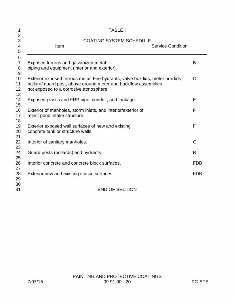
PAINTING AND PROTECTIVE COATINGS 7/07/15 09 91 00 - 20 PC-STS
TABLE I 1 2
COATING SYSTEM SCHEDULE 3 Item Service Condition 4 5 6 Exposed ferrous and galvanized metal B 7 piping and equipment (interior and exterior). 8 9 Exterior exposed ferrous metal, Fire hydrants, valve box lids, meter box lids, C 10 ballard/ guard post, above ground meter and backflow assemblies 11 not exposed to a corrosive atmosphere 12 13 Exposed plastic and FRP pipe, conduit, and tankage. E 14 15 Exterior of manholes, storm inlets, and interior/exterior of F 16 reject pond intake structure. 17 18 Exterior exposed wall surfaces of new and existing F 19 concrete tank or structure walls 20 21 Interior of sanitary manholes. G 22 23 Guard posts (bollards) and hydrants. B 24 25 Interior concrete and concrete block surfaces. FDB 26 27 Exterior new and existing stucco surfaces FDB 28
29 30
END OF SECTION 31
EXCAVATION AND BACKFILL FOR PIPES 7/07/15 31 23 33 - 1 PC-STS
SECTION 31 23 33 1 2
EXCAVATION AND BACKFILL FOR PIPES 3 4 5 PART 1 – GENERAL 6 7 1.01 SCOPE OF WORK 8 9 A. This work covers clearing and grubbing, site work, excavation, and backfill 10
for sanitary sewers, force mains, potable water mains, reclaimed water 11 mains and their appurtenances. 12
13 1.02. BURNING 14 15
A. Burning of debris will not be permitted. 16 17
1.03 CLEAN-UP 18 19
A. Clean-up is an essential part of the work. As the work progresses and is 20 completed, the Contractor shall clean the various sites of all operations and 21 completely restore all work areas to the satisfaction of the Engineer and the 22 County. This clean-up shall be done as promptly as practical and shall not 23 be left until the end of the construction period. No part of the work shall be 24 considered complete, and no payment will be made, until clean-up is 25 completed. 26
27 B. It is the Contractor's responsibility to assure that all construction sites and 28
all other affected properties are restored to a condition equal to, or better 29 than, the existing conditions prior to construction. All restoration is subject 30 to the approval of the Engineer and/or Property Owners. 31
32 1.04 DRAINAGE 33 34
A. It is the responsibility of the Contractor to maintain the existing drainage 35 systems during construction. Any damage done to an existing drainage 36 structure or system is to be immediately repaired to a condition equal to or 37 better than its original condition. 38
39 1.05 DUST CONTROL 40 41
A. It is the responsibility of the Contractor to control all dust problems that 42 may occur during the construction with required watering. Dust control will 43 be required seven days a week. 44
45 46

EXCAVATION AND BACKFILL FOR PIPES 7/07/15 31 23 33 - 2 PC-STS
1.06 SPRINKLERS 1 A. The Contractor shall be responsible for sprinklers encountered within the 2
area of excavation and shall make sure that if disturbed or damaged, they 3 shall be rebuilt to the satisfaction of the Engineer or property Owner and 4 with no additional cost to the County. 5
6 1.07 EROSION CONTROL 7 8 A. It is the Contractor's responsibility to erect suitable silt fences, hay bales or 9
other erosion runoff control devices prior to commencement of earth moving 10 or excavation activities. The Contractor shall be responsible for maintaining 11 the silt fences, hay bales or other erosion runoff control devices in an 12 effective manner, repairing or replacing damaged or ineffective section 13 during the course of the work until a ground cover of grass is established 14 and final environmental approval has been obtained. 15
16 1.08 PERMITS FOR DEWATERING OPERATIONS 17 18 A. The Contractor is responsible for obtaining all permits required for 19
dewatering discharges, including a Florida Department of Environmental 20 Protection Generic Permit for Produced Groundwater. 21
22 PART 2 - PRODUCTS 23 24 2.01 MATERIALS 25 26
A. General 27 28
1. Materials for use as fill are described below. For each material, the 29 Contractor shall notify the testing lab of the source of the material at 30 least ten (10) calendar days prior to the date of anticipated use of 31 such material. 32
33 2. Materials shall be furnished as required from off site sources and 34
hauled to the site. 35 36
3. Disposal of unsuitable material is specified in this Section. 37 38
B. Common Fill 39 40
1. Common fill shall consist of mineral soil, free of organic material, 41 loam, wood, trash and other objectionable materials, which may be 42 compressible or which cannot be compacted properly. Common fill 43 shall not contain stones larger than four inches in any dimension, 44 broken concrete, masonry, rubble, or other similar materials. It 45

EXCAVATION AND BACKFILL FOR PIPES 7/07/15 31 23 33 - 3 PC-STS
shall have physical properties such that it can be readily spread 1 and compacted during filling. 2
3 2. Material falling within the above Specification, encountered during 4
the excavation, may be stored in segregated stockpiles for reuse. 5 All material, which in the opinion of the Engineer, is not suitable for 6 reuse shall be spoiled as specified herein for disposal of unsuitable 7 materials. 8
9 C. Crushed Stone 10
11 1. Crushed stone for pipe bedding shall be FDOT No. 57 in 12
accordance with Section 901-2 of the FDOT Standard 13 Specifications for Road and Bridge Construction. 14
15 D. Select Fill 16
17 1. Select fill shall be noncohesive, non-plastic material free of all 18
debris, lumps or clods. Fill material shall be clean earth fill 19 composed of sand or an approved mixture of clay and sand. 20 Backfill material placed within one foot of piping and appurtenances 21 shall not contain any stones or rocks larger than two inches in 22 diameter, or three-quarter inch in diameter for PVC pipe. 23
24 PART 3 - EXECUTION 25 26 3.01 SAFETY PRECAUTIONS AND TEMPORARY WORKS 27 28
A. The Contractor shall provide and maintain adequate barricades, construction 29 signs, torches, flashers and guards as required in pedestrian and vehicular 30 traffic areas. All safety rules and regulations of local authorities shall be 31 observed. Local fire officials shall be kept advised of roads closed and roads 32 re-opened. 33
34 B. Where required, the Contractor shall provide suitable crossings at street 35
intersections and driveways, and supply such aid, as may be required for 36 pedestrians and motorists, including delivery vehicles, to safely negotiate the 37 construction area. "Street Closed to Through Traffic" signs and "Detour" 38 routes shall be indicated and maintained by the Contractor when the job is 39 located in a public or private street or way. In the case of dead end streets, 40 the Contractor shall advise all concerned residents and make all 41 arrangements to maintain reasonable ingress and egress for the residents. 42 Particular attention shall be given to residents in bad health, emergencies 43 and emergency vehicles. The Contractor shall be responsible for building 44 and maintaining all by-pass roadway areas and restoring those areas to their 45 original condition. 46
C. The Contractor shall furnish temporary or permanent support, adequate 47 protection and maintenance of all underground facilities and utilities 48
EXCAVATION AND BACKFILL FOR PIPES 7/07/15 31 23 33 - 4 PC-STS
encountered. Support, protection, maintenance and restoration are the 1 Contractor's responsibility at no additional cost to the County. 2
3 3.02 CLEARING AND GRUBBING 4 5
A. The Contractor shall remove only vegetation such as trees, shrubs, and 6 grass which interferes with the construction, as may be determined by the 7 Engineer, and he shall preserve and protect all other existing vegetation. 8
9 3.03 EXCAVATION 10 11 A. General 12 13
1. The Contractor shall perform all excavation of every description, and 14 of whatever substances encountered, to the depth indicated on the 15 Drawings, or as otherwise specified. 16
17 2. Trench excavation shall be such that the pipe can be laid to the 18
alignment and grade required. Trenches shall be shored and drained 19 in such a manner that work may proceed safely and efficiently. 20
21 3. Trench dewatering pumps shall discharge to natural drainage 22
channels, drains or sewers and shall be adequate to remove 23 accumulated storm and/or subsurface water. The Contractor shall 24 take necessary action to prevent surface water from flowing into the 25 trenches. It is the responsibility of the Contractor to assure that all 26 trench walls and trench bottoms are dry and remain dry during 27 pipeline construction. 28
29 4. The Contractor shall separate, remove and dispose of excavated 30
material not suitable for backfill, as directed by the Engineer. 31 32
5. All excavated material retained for backfill shall be piled in such a 33 manner as not to endanger the work or obstruct the sidewalks, 34 driveways or drainage. Fire hydrants, valve pit covers and hoses, 35 curb stop boxes, fire and police call boxes and other utility controls 36 shall be unobstructed and accessible at all times during construction. 37
38 B. Unclassified Excavation 39
40 1. Unclassified excavation shall include soil, clay, silt, sand, muck, 41
gravel, hardpan, loose shale, loose stones in masses and boulders 42 measuring less than one-half cubic yard in volume. 43
44 45 C. Classified Excavation 46 47
EXCAVATION AND BACKFILL FOR PIPES 7/07/15 31 23 33 - 5 PC-STS
1. Classified excavation shall be rock further defined as follows: 1 boulders, measuring one-half cubic yard or more in volume, rock 2 material in ledges, bedded deposits and unstratified masses, 3 conglomerate deposits firmly cemented and concrete or masonry 4 structures, except sidewalks and paving, that in the opinion of the 5 Engineer required for its removal drilling and blasting, wedging, 6 sledging, barring or breaking up with a power operated hand tool. 7
8 2. No soft or disintegrated rock that can be removed with a hand pick or 9
power operated excavator or shovel, no loose, shaken, or previously 10 blasted rock or broken stone in rock fillings or elsewhere, and no rock 11 exterior to the minimum limits of measurement allowed, which may 12 fall into the excavation, will be considered as rock. 13
14 3.04 TRENCH PREPARATION 15
16 A. Unsupported trench width shall be limited to the minimum practicable width 17
allowing working space to place and compact the haunching material. The 18 maximum width shall be the pipe diameter plus one foot on each side of the 19 pipe at springline for pipe in unsupported trenches. In sheeted trenches the 20 width of trench between faces of the sheeting shall be adequate to allow the 21 pipe bedding and haunching to be placed and completed, and the sheeting 22 removed without disturbing the bedding and haunching material within two) 23 pipe diameters on each side of the pipe. Trench boxes and moveable 24 sheeting shall be wide enough to allow moving without disturbing the 25 bedding and haunching within two pipe diameters on each side of the pipe. 26 Trench boxes and moveable sheeting shall be constructed and used in the 27 trench to avoid disturbing the piping, bedding and haunching when being 28 moved forward in the trench. 29 30
B. Dewatering of the trench bottom shall be accomplished using adequate 31 means to allow preparation of bedding, placement of haunching and pipe in 32 a trench environment without standing water. Dewatering shall continue 33 until sufficient backfill is placed above the pipe to prevent flotation. 34
35 C. The trench shall be dug so that the pipe can be laid to the alignment and 36
depth required, and it shall be excavated only so far in advance of the pipe 37 laying as allowed by the Engineer. The trench shall be so braced and 38 drained that the workmen may work in it safely and efficiently. All trench 39 preparation shall comply with all of the latest applicable Local, State 40 (Florida Trench Safety Act) and Federal Regulations (OSHA: Safe Trench 41 Act). It is essential that the discharge of the trench dewatering pumps be 42 conducted to natural drainage channels, drains or storm sewers. 43
44 D. Bell holes shall be provided at each joint to permit the joint to be made 45
properly. Ledge rock, boulders and large stones shall be removed to 46
EXCAVATION AND BACKFILL FOR PIPES 7/07/15 31 23 33 - 6 PC-STS
provide a clearance of six inches on all pipe twenty-four (24) inches and 1 smaller and nine inches on pipe larger than twenty-four (24) inches. If 2 such removal is required, backfilling will be done with selected material 3 approved by the Engineer and tamped to establish the proper grade. 4
5 E. Trench Bottom 6 7
1. Where the bottom of the trench at subgrade is found to be unstable 8 or to include ashes, cinders, refuse, vegetable or other organic 9 matter, or large pieces or fragments of inorganic material that, in 10 the judgment of the Engineer, should be removed, the Contractor 11 shall excavate and remove such unsuitable material to the width 12 and depth as directed by the Engineer. Before the pipe is laid, the 13 subgrade shall be made by backfilling with an approved material in 14 three inch uncompacted layers. The layers shall be thoroughly 15 tamped as specified by the Engineer to provide the uniform and 16 continuous bearing support as heretofore described. 17
18 2. The trench shall be dry when the bottom is prepared. The trench 19
bottom shall be excavated, or filled and compacted, as required to 20 bring it to grade and shaped to receive and support the pipe barrel. In 21 addition, bell holes shall be excavated so that after placement only 22 the barrel of the pipe receives bearing pressure from and is uniformly 23 supported by, the bottom of the trench. Preparation of the trench 24 bottom and placement of the pipe shall be such that the final position 25 of the pipe is true to line and grade, and uniformly supported 26 throughout the barrel of each length. When pipe is placed in refill 27 material, additional refill of the same material shall be tamped on 28 each side of the barrel to the springline, thus forming a trough of firm 29 bedding. 30
31 F. All materials that, in the opinion of the Engineer, are suitable for reuse in 32
restoring the disturbed surface shall be kept separated from the general 33 excavation material and can only be used as directed by the Engineer. 34
35 G. All excavated material shall be piled in a manner that will not endanger the 36
work and that will avoid obstructing sidewalks and driveways. Hydrants, 37 valve pit covers, valve boxes, curb stop boxes, fire and police call boxes, 38 or other utility controls shall be left unobstructed and accessible until the 39 work is completed. Gutters, drainage inlets, natural water courses and 40 miscellaneous drainage structures shall be kept clear or other satisfactory 41 provisions made for their proper operation. 42
43 H. Hand methods for excavation shall be employed when damage to existing 44
facilities is likely if heavy equipment is utilized or as directed by the 45 Engineer. 46
EXCAVATION AND BACKFILL FOR PIPES 7/07/15 31 23 33 - 7 PC-STS
1 3.05 DEPTH 2
3 A. Gravity Sewers 4 5
1. The depth of trenches for gravity sewers shall be such that the invert 6 of the pipe will be at elevations shown on the plan .Gravity sewers 7 shall be on straight alignment and constant grade between manholes. 8
9 10 B. Overdepth 11 12
1. When classified excavation is required, the rock shall be excavated to 13 a minimum depth of six inches below the trench depths as indicated 14 on the drawings or Specifications. Authorized overdepths in rock 15 excavation shall be refilled to grade with loose granular moist earth or 16 shell thoroughly tamped in place. 17
18 C. Trench shall be excavated to the depth required so as to provide a uniform 19
and continuous bearing and support for the pipe on solid and undisturbed 20 ground at every point between bell holes, except as necessary for removal 21 of pipe slings or other lifting tackle. Any part of the bottom of the trench 22 excavated to a point below the specified grade shall be corrected with 23 approved material at the Contractor's expense and thoroughly tamped as 24 directed by the Engineer. 25
26 D. Wherever unstable soil or muck that is determined by the Engineer to be 27
incapable of properly supporting the pipe is encountered in the bottom of the 28 trench, such material shall be removed to the required depth and the trench 29 refilled as specified to proper grade. If, in the opinion of the Engineer, 30 removal of the unstable material by this method is impractical, then the 31 Contractor shall support the pipe as detailed on the plans, or as directed by 32 the Engineer. 33
34 3.06 BACKFILL 35 36 A. General 37 38
1. The Contractor shall not perform any of the backfilling operations until 39 after he has inspected the lines and found them to be acceptable to 40 the County. 41
42 2. Backfill material shall consist of earth, loam, sandy clay, sand, gravel, 43
soft shale or other materials, free from organic materials, large clods 44 of earth, or stones. Where excavated material is not suitable for 45
EXCAVATION AND BACKFILL FOR PIPES 7/07/15 31 23 33 - 8 PC-STS
backfill, it shall be replaced by excess excavated material from other 1 areas. 2
3 3. In all areas, backfill material shall be deposited in six -inch layers and 4
carefully tamped until the compacted backfill depth reaches one foot 5 above the top of pipe. 6
7 4. No mechanical equipment, or machinery other than a hand operated 8
mechanical vibrator, will be allowed within the trench area until the 9 backfill has been properly tamped to one foot above the top of pipe. 10 The remainder of the backfill shall be deposited in one foot layers and 11 thoroughly tamped. Settling the backfill with water will be permitted, if 12 approved by the Engineer. 13
14 5. Where trenches are improperly backfilled, or where settlement 15
occurs, the trenches shall be reopened to the depth required for 16 proper compaction, refilled and compacted, and the surface restored 17 to the required grade and compaction, mounded over and smoothed 18 off. 19
20 B. Gravity Sewers 21
22 1. Haunching of native material shall be placed to the springline and 23
compacted. If ground water, or trench bottom conditions, is such as 24 to require use of Class I material, either to aid in dewatering, or to 25 provide foundation and bedding for the pipe, the haunching shall also 26 be of Class I material. Class I material contains angular, 1/4 inch to 27 1 1/2 inch graded stone. Care shall be taken to place the haunching 28 material, without voids, completely filling the trench from pipe wall to 29 trench wall. 30
31 C. Compaction Requirements 32
33 1. Trenches located under pavement or inside the two feet horizontal to 34
one foot vertical slope, downward from roadway shoulder or the back 35 of curb and from spring line to bottom of sub-grade or the finished 36 surface of the embankment, as appropriate, shall be compacted to a 37 density of one hundred (100) percent as determined by AASHTO T-38 99 Method C. 39
40 41 42 2. Trenches located outside of the two feet horizontal to one foot vertical 43
slope downward from roadway shoulder or the back of curb and 44 where no vehicular traffic will pass over the trenches, back fill shall be 45 compacted to a density approximately equal to that soil adjacent to 46
EXCAVATION AND BACKFILL FOR PIPES 7/07/15 31 23 33 - 9 PC-STS
the trench but not less than ninety-five (95) percent of the maximum 1 density as determined by AASHTO T-99, Method-C. 2
3 3. Backfill testing shall be performed in accordance with Pinellas County 4
Minimum Testing Frequency Requirements, latest edition, unless 5 called out differently by the Engineer on the plan documents. 6
7 D. Testing of Backfill 8 9
1. Trenching within, or across roadways, or other areas to be paved, or 10 stabilized shall be backfilled and compacted to their full depth. 11 Compaction shall be as specified in the Special Provisions or on the 12 Plans. 13
14 2. Density tests for backfilled trenches within, or across roadways, shall 15
be performed as specified or as directed by the Engineer, with at 16 least one test taken at different locations for each vertical foot 17 beginning from two feet over pipe to ground level. 18
19 3. Backfill testing shall be performed in accordance with Pinellas County 20
Minimum Testing Frequency Requirements, latest edition, unless 21 called out differently by the Engineer on the plan documents. 22
23 4. Where unsatisfactory compaction is revealed by the test, the 24
Contractor shall re-excavate, backfill, re-compact and/or rework the 25 backfill as required, to obtain the required degree of compaction over 26 the entire depth of the trench. 27
28 5. Satisfactory backfill compaction is an integral part of pipe laying, 29
paving, and stabilizing. Satisfactory density reports shall be on file 30 before each Contractor's statement is submitted for payment. 31
32 E. Disturbance of Sewer Mains 33 34
1. Sewer mains shall be checked by the Contractor to determine 35 whether any displacement of the pipe has occurred after the trench 36 has been backfilled to two feet above the pipe. If such inspection 37 shows poor alignment, displaced pipe or any defects, these defects 38 shall be remedied to the satisfaction of the Engineer by the 39 Contractor at his expense. 40
41 42 3.07 DISPOSAL OF SURPLUS MATERIAL 43 44
A. All excavated material not required or not suitable for fill, or backfill, shall be 45 disposed of by the Contractor, as directed by the Engineer. 46

EXCAVATION AND BACKFILL FOR PIPES 7/07/15 31 23 33 - 10 PC-STS
1 B. Material suitable for backfill is to be stockpiled on, or near site, until released 2
by the Engineer for disposal. 3 4 3.08 SHEETING AND BRACING 5 6 A. The Contractor shall do all shoring and sheeting required to perform and 7
protect the excavation and, as required, for the safety of the employees. 8 9 B. All trenches shall be sheeted and braced as required by the Engineer and 10
all applicable Federal, State, County and Municipal regulations. Sheeting 11 and bracing shall be used to prevent shifting of adjacent soil and to 12 prevent damage to structures or the work. The sole responsibility for the 13 design, methods of installation, and adequacy of the sheeting and bracing, 14 shall be and shall remain that of the Contractor. 15
16 C. Sheeting and bracing or approved laying box shall be used in all trenches 17
unless the slopes are excavated until the natural angle of repose of the 18 soil is encountered. 19
20 D. In general, sheeting and bracing shall be removed as the excavation is 21
backfilled in such a manner as to avoid the caving in of the bank or 22 disturbance of adjacent areas or structures. The voids left by withdrawal 23 of the sheeting and bracing shall be carefully filled by jetting, ramming or 24 other means approved by the Engineer. Permission shall be obtained 25 from the Engineer prior to removal of any sheeting or bracing. Permission 26 shall not relieve the Contractor of any responsibility for damage due to 27 failure to leave such sheeting and bracing in place. 28
29 E. The Engineer may order, in writing, any or all sheeting or bracing to be left 30
in place for the purpose of preventing injury to adjacent structures, 31 property, etc. If left in place, such sheeting shall be cut off at the elevation 32 ordered, but in no case less than thirty-six (36) inches below the existing 33 grade. Bracing remaining in place shall be driven in tight. The right of the 34 Engineer to order sheeting and bracing to remain in place shall not be 35 construed as creating any obligation on his part to issue such orders. 36 Payment for sheeting and bracing, unless specifically called for on the 37 Drawings shall not be paid under separate item, but shall be included in 38 the payment for other items of Work. 39
40 3.09 DEWATERING BY WELLPOINT 41 42 A. Wellpoints shall be spaced and at sufficient depths as required to 43
eliminate water during the excavation period until the work is completed. 44 Ample means and equipment shall be provided with which to remove 45 promptly, and dispose properly all water entering any excavation. This 46

EXCAVATION AND BACKFILL FOR PIPES 7/07/15 31 23 33 - 11 PC-STS
includes the use of sand or gravel as required to maintain adequate flow 1 during the pipe laying or installation of other items of work within the 2 excavation. 3
4 B. Water pumped or drained shall be disposed of in a suitable manner 5
without damage to adjacent property to other work under construction or 6 to street pavements or public parks. Water shall not be discharged onto 7 streets without adequate protection of the surface at the point of 8 discharge. All gutter, drains, culverts, sewers and inlets shall be kept 9 clean and open for surface drainage. Water shall not be directed across 10 or over pavements except through approved pipes or properly constructed 11 troughs. Contractor shall obtain permission from the owner of any 12 property involved before digging ditches or constructing water courses for 13 removal of water, and provide for disposal of the water without ponding or 14 creating a public nuisance. Water may be discharged into storm sewers. 15 Payment for dewatering shall not be paid for under a separate item, but 16 shall be included in the payment for other items of work, unless it is 17 specifically included as a Pay Item in the Contract. 18
19 3.10 APPURTENANCES 20 21
A. Excavation for manholes and other appurtenances shall be made to size 22 that will allow at least twelve (12) inches between their outer surfaces and 23 the embankment or shoring. Overdepth excavation and backfill to required 24 depth below such appurtenances that have not been directed by the 25 Engineer shall be at the expense of the Contractor. 26
27 28
END OF SECTION 29 30 31 32 33 34 35 36 37 38 39 40 41 42 43 44 45 46
EXCAVATION AND BACKFILL FOR STRUCTURES 7/07/15 31 23 34 - 1 PC-STS
SECTION 31 23 34 1 2
EXCAVATION AND BACKFILL FOR STRUCTURES 3 4 5 PART 1 - GENERAL 6 7 1.01 SCOPE OF WORK 8 9
A. This work involves clearing and grubbing, site work, excavation and 10 backfill for sanitary sewer manholes, wet wells and other buried utility 11 structures. 12
13 1.02 BURNING 14 15
A. Burning of debris will not be permitted. 16 17 1.03 CLEANUP 18 19
A. Cleanup is an essential part of the work. As the work progresses and is 20 completed, the Contractor shall clean the site of all operations and 21 completely restore the area to the satisfaction of the Engineer. This 22 cleanup shall be done as promptly as practicable and shall not be left until 23 the end of the construction period. No part of the work shall be 24 considered complete and no payment will be made until cleanup is 25 completed. 26
27 B. It is the Contractor's responsibility to assure that all construction sites and 28
all other affected properties are restored to a condition equal to, or better 29 than, the existing conditions prior to construction. All restoration is subject 30 to the approval of the Engineer. 31
32 1.04 DRAINAGE 33 34
A. It is the responsibility of the Contractor to maintain the existing drainage 35 systems during construction. Any damage done to an existing drainage 36 structure or system is to be immediately repaired to a condition equal to or 37 better than its original condition. 38
39 1.05 DUST CONTROL 40 41
A. It is the responsibility of the Contractor to control all dust problems that 42 may occur during the construction with required watering. Dust control will 43 be required seven days a week. 44
45 1.06 SPRINKLERS 46

EXCAVATION AND BACKFILL FOR STRUCTURES 7/07/15 31 23 34 - 2 PC-STS
1 A. The Contractor shall be responsible for sprinklers encountered within the 2
area of excavation and shall make sure that if disturbed or damaged, they 3 shall be rebuilt to the satisfaction of the Engineer and with no additional 4 cost to the County. 5
6 1.07 EROSION CONTROL 7 8
A. It is the Contractor's responsibility to erect suitable silt fences, hay bales or other 9 erosion runoff control devices prior to commencement of earth moving or 10 excavation activities at the locations indicated on the plans. The Contractor shall 11 be responsible for maintaining the silt fences, hay bales or other erosion runoff 12 control devices in an effective manner, repairing or replacing damaged or 13 ineffective section during the course of the work until a ground cover of grass is 14 established. 15
16 1.08 PERMITS FOR DEWATERING OPERATIONS 17 18 A. The Contractor is responsible for obtaining all permits required for 19
dewatering discharges, including a Florida Department of Environmental 20 Protection Generic Permit for Produced Groundwater. 21
22 PART 2 – PRODUCTS 23 24 2.01 FILL MATERIALS 25 26
A. Compacted granular fill which will provide support for building or structure 27 foundations will be referred to as "structural fill." Backfill which is placed 28 against the exterior side of the building walls or structures, or as fill over 29 pipe lines, will be referred to as "common fill." 30
31 B. Materials for compacted structural granular fill shall be gravel, sandy 32
gravel, or gravely sand free of organic material, loam, wood, trash, and 33 other objectionable material and shall be well-graded within the following 34 limits: 35
Sieve Size 6-in. 100 37
Percent Finer by Weight 36
No. 4 20 - 95 38 No. 40 0 - 60 39
No. 200 0 - 8 40 41 C. Common Fill 42
43 1. Common fill shall consist of mineral soil, free of organic material, 44
loam, wood, trash and other objectionable material which may be 45 compressible or which cannot be compacted properly. Common fill 46
EXCAVATION AND BACKFILL FOR STRUCTURES 7/07/15 31 23 34 - 3 PC-STS
shall not contain stones larger than ten (10) inches in any 1 dimension, broken concrete, masonry, rubble or other such 2 materials. It shall have physical properties such that it can be 3 readily spread and compacted during filling. 4
5 2. Material falling within the above Specification, encountered during 6
the excavation, may be stored in segregated stockpiles for reuse. 7 All material which, in the opinion of the Engineer, is not suitable for 8 reuse shall be spoiled as specified herein for disposal of unsuitable 9 materials. 10
11 D. Crushed Stone 12
13 1. Crushed stone shall be used for a drainage layer below structures 14
with underdrains and at other locations indicated on the Drawings. 15 16
2. Crushed stone shall be size No. 57 with gradation as noted in Table 17 1, Section 901 of Department of Transportation, Construction of 18 Roads and Bridges. 19
20 2.02 UNSUITABLE MATERIAL 21 22
A. Highly organic soil ASTM D 2487 Group PT, topsoil, roots, vegetable 23 matter, trash and debris. 24
25 PART 3 – EXECUTION 26 27 3.01 SAFETY PRECAUTIONS AND TEMPORARY WORKS 28 29
A. The Contractor shall provide and maintain adequate barricades, construction 30 signs, torches, flashers and guards as required in pedestrian and vehicular 31 traffic areas. All safety rules and regulations of local authorities shall be 32 observed. Local fire officials shall be kept advised of roads closed and roads 33 re-opened. 34
35 B. Where required, the Contractor shall provide suitable crossings at street 36
intersections and driveways, and supply such aid, as may be required for 37 pedestrians and motorists, including delivery vehicles, to safely negotiate the 38 construction area. "Street Closed to Through Traffic" signs and "Detour" 39 routes shall be indicated and maintained by the Contractor when the job is 40 located in a public or private street or way. In the case of dead end streets, 41 the Contractor shall advise all concerned residents and make all 42 arrangements to maintain reasonable ingress and egress for the residents. 43 Particular attention shall be given to residents in bad health, emergencies 44 and emergency vehicles. The Contractor shall be responsible for building 45 and maintaining all by-pass roadway areas and restoring those areas to their 46 original condition. 47
EXCAVATION AND BACKFILL FOR STRUCTURES 7/07/15 31 23 34 - 4 PC-STS
1 C. The Contractor shall furnish temporary or permanent support, adequate 2
protection and maintenance of all underground facilities and utilities 3 encountered. Support, protection, maintenance and restoration are the 4 Contractor's responsibility at no additional cost to the County. 5
6 3.02 CLEARING AND GRUBBING 7 8
A. The Contractor shall remove only vegetation such as trees, shrubs, and 9 grass which interfere with the construction, as may be determined by the 10 Engineer, and he shall preserve and protect all other existing vegetation. 11
12 3.03 JOB CONDITIONS 13 14
A. Lateral Support of Excavation for Structures 15 16
1. Furnish, put in place, and maintain sheeting and bracing required to 17 support the sides of the excavations, to prevent any movement 18 which could in any way diminish the width of the excavation below 19 that necessary for proper construction, and to protect structures, 20 pipe and utilities from damage due to lateral movement or 21 settlement of ground. If the Engineer is of the opinion that at any 22 point sufficient or proper supports have not been provided, he may 23 order additional supports put in at the expense of the Contractor, 24 and compliance with such order shall not relieve or release the 25 Contractor from his responsibility for the sufficiency of such 26 supports. 27
28 B. Dewatering for Structures 29
30 1. Furnish, install, maintain, operate, and remove a temporary 31
dewatering system, as required to lower and control the 32 groundwater level, so that the structures may be constructed in the 33 dry. The Contractor shall, at his own expense, correct all damage 34 resulting from inadequacy of the dewatering system or from 35 flooding or the construction site from other causes. 36
37 2. The dewatering system shall be adequate to drain any excavated 38
area, to maintain the water at such a level as to permit construction 39 in the dry, and to maintain the lowered water table until the 40 structure has been completed to the required stages. 41
42 3. Continuously maintain excavation in a dry condition to prevent 43
damage to the subsoil or fill during interruptions due to weather, 44 labor strikes, power failures or other delays. Provide and have 45 ready for immediate use at all times diesel or gasoline powered 46

EXCAVATION AND BACKFILL FOR STRUCTURES 7/07/15 31 23 34 - 5 PC-STS
standby pumping units to serve the system in case of failure of the 1 normal pumping units. 2
3 4. Piping and boiling, or any form of uncontrolled seepage, in the 4
bottom or sides of the excavation shall be prevented at all times. If 5 for any reason the dewatering system is found to be inadequate to 6 meet the requirements set forth herein, the Contractor shall, at his 7 own expense, make such additions, changes and/or replacements 8 as necessary to provide a satisfactory dewatering system. 9
10 C. Control of Groundwater Level 11
12 1. Maintain the groundwater level at or below subgrade of the 13
structure until the concrete structures are up high enough to: (1) 14 prevent flooding the structure, (2) support both bottom and top 15 levels of walls, and (3) prevent flotation. 16
17 2. After the structure has been completed in its entirety, backfill as 18
described hereinafter. 19 20
3. Flotation shall be prevented by maintaining a positive and 21 continuous operation of the dewatering system. The Contractor 22 shall be fully responsible and liable for all damages which may 23 result from failure of this system. 24
25 4. Disposal of drainage water shall be in an area approved by the 26
Engineer. Precautions shall be taken to prevent the flow or 27 seepage of drainage back into the drainage area. Particular care 28 shall be taken to prevent the discharge of unsuitable drainage to a 29 water supply or surface water body. 30
31 5. Removal of the dewatering system shall be accomplished after the 32
dewatering system is no longer required. 33 34 3.04 EXCAVATION 35 36 A. General 37 38
1. The Contractor shall perform all excavation of every description, and 39 of whatever substances encountered, to the depth indicated on the 40 Drawings, or as otherwise specified. 41
42 2. Excavation shall be such that the structures can be installed at the 43
grades required. Excavations shall be shored and drained in such a 44 manner that work may proceed safely and efficiently. 45
46

EXCAVATION AND BACKFILL FOR STRUCTURES 7/07/15 31 23 34 - 6 PC-STS
3. Dewatering pumps shall discharge to natural drainage channels, 1 drains or sewers and shall be adequate to remove accumulated 2 storm and/or subsurface water. The Contractor shall take necessary 3 action to prevent surface water from flowing into the excavations. It is 4 the responsibility of the Contractor to assure that all excavation walls 5 and bottoms are dry and remain dry during construction. 6
7 4. The Contractor shall separate, remove and dispose of excavated 8
material not suitable for backfill, as directed by the Engineer. 9 10
5. All excavated material retained for backfill shall be piled in such a 11 manner as not to endanger the work or obstruct the sidewalks, 12 driveways or drainage. Fire hydrants, valve pit covers and hoses, 13 curb stop boxes, fire and police call boxes and other utility controls 14 shall be unobstructed and accessible at all times during construction. 15
16 B. Unclassified Excavation 17
18 1. Unclassified excavation shall include soil, clay, silt, sand, muck, 19
gravel, hardpan, loose shale, loose stones in masses and boulders 20 measuring less than one-half cubic yard in volume. 21
22 C. Classified Excavation 23 24
1. Classified excavation shall be rock further defined as follows: 25 boulders, measuring one-half cubic yard or more in volume, rock 26 material in ledges, bedded deposits and unstratified masses, 27 conglomerate deposits firmly cemented and concrete or masonry 28 structures, except sidewalks and paving, that in the opinion of the 29 Engineer required for its removal drilling and blasting, wedging, 30 sledging, barring or breaking up with a power operated hand tool. 31
32 2. No soft or disintegrated rock that can be removed with a hand pick or 33
power operated excavator or shovel, no loose, shaken, or previously 34 blasted rock or broken stone in rock fillings or elsewhere, and no 35 rock exterior to the minimum limits of measurement allowed, which 36 may fall into the excavation, will be considered as rock. 37
38 3.05 STRUCTURE EXCAVATION AND COMPACTION PROCEDURES - GENERAL 39 40
A. Excavation shall be made to such widths as will give suitable room for 41 construction of the structures, for bracing and supporting, pumping and 42 drainage; and the bottom of the excavations shall be rendered firm and 43 dry and in all respects acceptable to the Engineer. 44
45

EXCAVATION AND BACKFILL FOR STRUCTURES 7/07/15 31 23 34 - 7 PC-STS
B. Excavation and dewatering shall be accomplished by methods which 1 preserve the undisturbed state of subgrade soils. Subgrade soil which 2 becomes soft, loose, "quick," or otherwise unsatisfactory for support of 3 structures as a result of inadequate excavation, dewatering or other 4 construction methods shall be removed and replaced by structural fill as 5 required by the Engineer at the Contractor's expense. 6
7 C. Dewatering shall be such as to prevent boiling or detrimental 8
underseepage at the base of the excavation as specified herein. The 9 Contractor shall install such means as required to preserve the stability of 10 the base of the operation. 11
12 D. Excavating equipment shall be satisfactory for carrying out the work in 13
accordance with the Specifications. In no case shall the earth be 14 ploughed, scraped or dug with machinery so near to the finished subgrade 15 as to result in excavation of, or disturbance of material below grade, the 16 last of the excavated material being removed with pick and shovel just 17 before placing of concrete or working mat thereon. 18
19 E. During final excavation to subgrade level, take whatever precautions are 20
required to prevent disturbance and remolding of the subgrade. Material 21 which has become softened and mixed with water shall be removed. 22 Hand excavation of the final three to six inches will be required as 23 necessary to obtain a satisfactory undisturbed bottom. The Engineer will 24 be the sole judge as to whether the work has been accomplished 25 satisfactorily. 26
27 F. All structure areas shall be stripped, cleared and grubbed of all surface 28
vegetation and root laden top soils. 29 30
G. After stripping, the structure areas should be leveled sufficiently to permit 31 equipment traffic and then proof-rolled with a vibratory roller with at least a 32 twenty (20) ton static weight. Careful observations should be made during 33 proof-rolling of the stripped subgrade area to identify any areas of soft 34 yielding soils that may require over excavation and replacement. 35
36 H. Compaction should continue until the minimum density specified in the 37
Special Provisions or on the Plans is achieved. 38 39 3.06 BACKFILLING AND COMPACTION 40 41
A. Structural fill shall be placed in loose lifts not exceeding twelve (12) inches 42 and should be compacted to the minimum density specified in the Special 43 Provisions or on the plans. 44
45
EXCAVATION AND BACKFILL FOR STRUCTURES 7/07/15 31 23 34 - 8 PC-STS
B. Common fill may be used as backfill against the exterior walls of the 1 structures, including manholes, wet wells and storm structures, or in other 2 areas as designated by the Engineer. Common fill shall be placed in 3 loose lifts not exceeding twelve (12) inches and should be compacted to 4 the minimum density specified in the Special Provisions or on the plans. 5
6 C. Materials placed in fill areas shall be deposited to the lines and grades 7
shown on the Drawings making due allowance for settlement of the 8 material and for the placing of topsoil thereon. 9
10 D. The surfaces of filled areas shall be grades to smooth true lines, strictly 11
conforming to grades indicated on the paving and grading Drawings, and 12 no soft spots or uncompacted areas will be allowed in the work. 13
14 E. No compacting shall be done when the material is too wet either from rain 15
or from excess application of water. At such times, work shall be 16 suspended until the previously placed and new materials have dried 17 sufficiently to permit proper compaction. 18
19 F. Density tests shall be performed by an engineering testing laboratory as 20
specified or as directed by the Engineer. 21 22
G. When a density test is scheduled and a time agreed upon by the Engineer 23 and Contractor, it shall be the Contractor's responsibility to properly prepare 24 the area in advance. 25
26 H. Where unsatisfactory compaction is revealed by the test, the Contractor 27
shall re-excavate, backfill, re-compact and/or rework the backfill as required, 28 to obtain the required degree of compaction. 29
30 3.07 SHEETING LEFT IN PLACE 31 32
A. Where damage is likely to result from withdrawing sheeting, upon direction of 33 the Engineer, the sheeting shall be left in place. 34
35 3.08 DISPOSAL OF SURPLUS MATERIAL 36 37
A. All excavated material not required or not suitable for fill, or backfill, shall be 38 disposed of by the Contractor, as directed by the Engineer. 39
B. Material suitable for backfill is to be stockpiled on, or near site, until released 40 by the Engineer for disposal. 41
42 3.09 GRADING 43 44
A. Grading in preparation for placing of topsoil, planting areas, paved walks 45 and drives, and appurtenances shall be performed at all places that are 46 indicated on the Drawings, to the lines, grades, and elevations shown and 47

EXCAVATION AND BACKFILL FOR STRUCTURES 7/07/15 31 23 34 - 9 PC-STS
otherwise as directed by the Engineer. Such work shall be performed in a 1 manner that the requirements for formation of slopes, lines, and grades 2 can be followed. All material encountered, of whatever nature, within the 3 limits indicated, shall be removed and disposed of as directed. During the 4 process of grading, the subgrade shall be maintained in such condition 5 that it will be well drained at all times. When directed, temporary drains 6 and drainage ditches shall be installed to intercept or divert surface water 7 which may affect the progress or condition of the work. 8
9 B. If, at the time of grading, it is not possible to place any material in its 10
proper section of the permanent structure, it shall be stockpiled for later 11 use. No extra payment will be made for the stockpiling or double handling 12 of excavated material. 13
14 C. The right is reserved to make minor adjustments or revisions in lines or 15
grades, if found necessary as the work progresses, due to discrepancies 16 on the Drawings or in order to obtain satisfactory construction. 17
18 D. Stones or rock fragments larger than four inches in their greatest 19
dimensions will not be permitted in the top six inches of the finished 20 subgrade of all fills or embankments. 21
22 E. In cuts, all loose or protruding rocks on the back slopes shall be barred 23
loose or otherwise removed to line or finished grade of slope. All cut and 24 fill slopes shall be uniformly dressed to the slope, cross section, and 25 alignment shown on the Drawings or as directed by the Engineer. 26
27 F. No grading is to be done in areas where there are existing pipe lines that may 28
be uncovered or damaged until such lines have been located and it has been 29 determined if such lines must be maintained are relocated, or where lines are 30 to be abandoned, all required valves are closed and remaining pipes are 31 plugged. 32
33 34
END OF SECTION 35
STABILIZED AND ASPHALT ROADWAY RESTORATION 7/07/15 32 12 01 - 1 PC-STS
SECTION 32 12 01 1 2
STABILIZED AND ASPHALT ROADWAY RESTORATION 3 4
PART 1 – GENERAL 5 6 1.01 SCOPE OF WORK 7 8
A. Contractor shall furnish all labor and materials required to restore 9 stabilized roadways and asphalt paving as specified herein. 10
11 B. Workmanship and materials shall be in accordance with Department of 12
Transportation requirements for new pavement for roads under their 13 jurisdiction. Any local or County Road shall be restored in accordance 14 with permits or ordinances of the municipality having jurisdiction over such 15 road or street. Restoration of flexible pavement shall conform to the 16 approved permit or utility license for each road crossing. 17
18 C. Where applicable, all work shall conform to the Technical Specifications of 19
Florida Department of Transportation "Standard Specifications for Road 20 and Bridge Construction", latest edition (Divisions II and III) and "Roadway 21 and Traffic Design Standards", latest edition, including any amendments 22 thereto. The Contractor shall acquire his own copies of the Department of 23 Transportation Standards. In the event of conflict between the 24 Department of Transportation Standards and the Specifications listed in 25 these documents, the Engineer shall determine which shall govern. 26
27 1.02 SUBMITTALS 28 29
A. Shop drawings for the proposed materials of construction, including an 30 asphalt job mix formula, shall be submitted to the Engineer for approval at 31 least two weeks prior to the application of stabilized or paved surfaces. 32
33 PART 2 – PRODUCTS 34 35 2.01 SUBBASE 36 37
A. Materials used should be high bearing value soil, sand-clay, ground 38 limestone, crushed limerock, coquina, or any other material suitable for 39 stabilization. Muck shall not be used. 40
41 2.02 BASE 42 43
A. Limerock for use as base material shall meet the requirements of Florida 44 Department of Transportation Standard Specifications for Road and 45 Bridge Construction, Section 911. The limerock producer shall address 46

STABILIZED AND ASPHALT ROADWAY RESTORATION 7/07/15 32 12 01 - 2 PC-STS
each truck receipt to the Contractor and the job site. Each receipt will 1 show the source of the material by D.O.T. pit number. One copy of each 2 receipt will be submitted daily to the County for his records. 3
4 B. Coquina shell used in the base course shall have an organic material of 5
not greater than 0.5 percent nor contain significant quantities of sand or 6 other impurities, which would prevent bonding. At least ninety-seven (97) 7 percent of the coquina used shall pass through a 3 1/ 2-inch ring. 8
9 C. Crushed concrete base material shall conform to the following gradation: 10
11 12
Sieve Size
Percent by
Weight Passing
2"
100
1 1/2"
95-100
3/4"
65-90
3/8"
45-75
No. 4
35-60
No. 10
24-45
No. 50
5-25
No. 200
0-10
13 14
1. Material for Crushed Concrete Base shall consist only of crushed 15 concrete and such additive materials as may be approved by the 16 Engineer for the purpose of facilitating construction and achieving 17 the desired characteristics of the finished in-place product. Material 18 which shows a significant tendency toward adverse chemical or 19 physical change on exposure to moisture will not be acceptable. 20 The material shall be free of any ferrous metals. 21
22

STABILIZED AND ASPHALT ROADWAY RESTORATION 7/07/15 32 12 01 - 3 PC-STS
2. The material shall not contain lumps, balls, or pockets of sand or 1 clay material in size or quantity sufficient to be detrimental to the 2 proper bonding, finishing or strength of the crushed concrete base. 3
4 3. The specific mechanical and physical properties of crushed 5
concrete aggregate and any additive materials permitted in the 6 construction of crushed concrete base shall be determined on the 7 basis of test results as the work progresses. 8
9 D. Reclaimed Asphalt Pavement Base 10 11
1. Reclaimed asphalt base material may be used on paved shoulders, 12 bike paths and other non-traffic applications. Materials shall be in 13 accordance with Section 283 of the FDOT Standard Specifications 14 for Road and Bridge Construction. 15
16 2.03 PRIME AND TACK COATS 17 18
A. Bituminous prime coats shall be applied to previously prepared bases. 19 Bituminous tack coats shall be placed on existing paved surfaces and 20 between successive lifts of asphalt material. 21
22 B. The prime coat shall be cut-back asphalt Grade RC-70 or RC-250, 23
emulsified asphalt Grades SS-I or CSS-I, or other types and grades of 24 bituminous material specified or approved by the Engineer. 25
26 C. The tack coat shall be emulsified asphalt, Grades RS-2, SSI-I, CSS-I, 27
SS-IH, CSS-IH, AS-60, AE-90, AE-150, or asphalt emulsion prime. 28 29 D. A cover material must be placed on the prime coat to insure that the prime 30
coat remains intact until the surface course is placed. 31 32 2.04 ASPHALT WEARING SURFACE 33 34
A. The bituminous wearing surface applied shall be that specified in the Plans 35 or contract documents. 36
37 B. Asphalt mixes for FDOT roadways shall be as required by the FDOT permit 38
or as specified. 39 40 C. If no asphalt mix is specified on Pinellas County roads, Type PC-III 41
asphaltic concrete shall be used as the paving material, unless otherwise 42 indicated. Design mix properties shall be in accordance with Pinellas 43 County’s Specifications. 44
45 46
STABILIZED AND ASPHALT ROADWAY RESTORATION 7/07/15 32 12 01 - 4 PC-STS
PART 3 - EXECUTION 1 2
3.01 PAVEMENT AND BASE REMOVAL 3 4
A. Pavement removal shall be held to the minimum width consistent with 5 good construction practice. The pavement material shall be carefully 6 separated from other excavated materials and will not be permitted to be 7 included in the backfill, but shall be satisfactorily disposed of by the 8 Contractor. Base materials may be salvaged and stockpiled for reuse as 9 stabilizer, subject to the approval of the Engineer. Reuse of salvaged 10 base material as new base material is not permitted. 11
12 3.02 ASPHALT REMOVAL 13 14
A. All asphalt street pavement removed shall be replaced with base and 15 surface materials which are of a quality and thickness equal to or more 16 than the materials removed. The edges of the paving shall be cut to neat 17 lines beyond any settled or broken areas. Pavement shall be replaced as 18 soon as practicable after compaction of backfill. 19
20 3.03 SURFACE TREATED STREETS 21
22 A. All surface treated streets removed shall be replaced with at least six 23
inches of compacted shell or limerock as directed by the Engineer. This 24 base shall be primed and sanded and maintained until overlayed. 25
26 3.04 REPLACING STABILIZED ROADWAY 27 28
A. The Contractor shall restore cuts in all stabilized roadway surfaces using 29 the same type and grade of material used on the existing street surface. 30 After the pipelines and/or appurtenances have been installed and properly 31 backfilled as herein specified, the Contractor shall bring the roadway 32 surface to grade and ready the surface to receive the stabilization 33 material. The stabilizing materials shall be of high-bearing value such as 34 sand, clay, oyster shell, coquina shell, rock screening, crushed concrete or 35 any other material which, as allowed by the agency with jurisdiction over 36 such road and that, in the opinion of the Engineer, is suitable for 37 stabilization. 38
39 B. The stabilizing material shall be applied in such quantities as may be 40
necessary to bring the top six inches of the roadway surface to a bearing 41 value as hereinafter specified and to the proper line and grade. The 42 material shall be incorporated with the roadbed material by plowing, 43 disking, harrowing, blading, and mixing with a rotary tiller, or any other 44 equipment approved by the Engineer. The mixed materials shall be of 45 uniform density throughout the width and depth of the layer being 46

STABILIZED AND ASPHALT ROADWAY RESTORATION 7/07/15 32 12 01 - 5 PC-STS
processed. After thoroughly mixing to a uniform texture, the surface shall 1 be compacted by rolling with any type of equipment that will produce the 2 density required. Compaction shall continue until the entire depth to be 3 stabilized has a value determined from tests made on the 6-inch 4 compacted thickness, of not less than the requirements set forth by the 5 agency having jurisdiction over the road. 6
7 3.05 RESURFACING 8 9
A. When pavement replacement is complete, certain streets as directed by 10 the County, shall be resurfaced for the full width of the existing paved 11 section. Resurfacing shall be consistent with the requirements set forth by 12 the governmental agency that has jurisdiction over the road. 13
14 B. Materials for resurfacing shall be as specified on the Drawings. 15
16 3.06 SUBBASE PREPARATION 17 18
A. Prior to installation of base material, the area shall be graded to within 19 0.2± feet, and soft, spongy or mucky material removed. Sufficient 20 stabilizing material shall be cut in to achieve a Florida Bearing Value 21 (FBV) in excess of 75 psi or limerock bearing ratio (LBR) greater than forty 22 (40) pounds at a minimum density of ninety-eight (98) percent of a 23 maximum density as defined and measured in ASSTHO T-180 (Modified 24 Proctor), to a six inch minimum depth. 25
26 B. Density tests for subbase materials shall be taken at three hundred (300) 27
foot intervals in a staggered pattern and around structures as required. If 28 compaction procedures allow, testing requirements may be reduced or 29 increased at the Engineer's discretion. 30
31 3.07 BASE COURSE CONSTRUCTION 32 33
A. General 34 35
1. The base course shall be constructed on the prepared subgrade, in 36 accordance with the Specifications and Plans. All base material 37 shall be placed in accordance with the lines, grades, notes, and 38 typical cross sections shown on the Plans. Any deviation from the 39 Plans is subject to the approval of the Engineer. Any deviations not 40 approved by the Engineer shall be repaired to the satisfaction of the 41 Engineer at no expense to the County. 42
43 44 45 46
STABILIZED AND ASPHALT ROADWAY RESTORATION 7/07/15 32 12 01 - 6 PC-STS
B. Limerock, Reclaimed Asphalt or Crushed Concrete Base Course 1 2
1. Base shall be spread by mechanical spreaders, equipped to produce 3 an even distribution with a uniform thickness. When the specified 4 compacted thickness of the base is greater than six inches, the base 5 shall be constructed in two courses. The thickness of the first course 6 shall be one-half the total thickness of the finished base. After 7 spreading is completed, the entire surface shall be scarified and 8 shaped so as to produce the required grade and cross section after 9 compaction. If two courses are required, each lift shall be prepared 10 as previously described. Prior to spreading of the upper course, 11 density tests will have been taken for the lower and determined to be 12 satisfactory. 13
14 2. When the material does not have the proper moisture content to 15
ensure the required density, it shall be wet or dried as required. 16 When adding water, it shall be uniformly mixed in by disking to the 17 full depth of the course that is being compacted. 18
19 3. All materials shall be compacted to a density of not less than 20
ninety-eight (98) percent of maximum density as determined by 21 AASHTO T 180. Density tests shall be taken at three hundred (300) 22 foot intervals in a staggered pattern and around structures as 23 required. Density determinations shall be made at more frequent 24 intervals, at no extra cost, if deemed necessary by the Engineer. 25
26 4. The finished surface of the base course shall be checked with a 27
template cut to the required crown and a fifteen foot straight edge laid 28 parallel to the center line of the road. All irregularities greater than 29 one-quarter inch shall be corrected to the satisfaction of the 30 Engineer. 31
32 5. The base material shall extend at least twelve (12) inches outside the 33
edge of the finished paved surface, unless otherwise indicated. 34 Thickness of the base shall be measured at two hundred (200) foot 35 intervals at various points in the cross section. Measurements shall 36 be taken at various points on the cross section through holes not less 37 than three inches in diameter and at locations, as specified by the 38 Engineer. Where the compacted thickness is deficient by one-half 39 inches or more, the Contractor shall correct the deficiency by 40 scarifying and adding material for a distance of one hundred (100) 41 feet in each direction from the edge of the deficient area. The 42 required thickness, compaction and cross section will then be 43 achieved. 44
45 46

STABILIZED AND ASPHALT ROADWAY RESTORATION 7/07/15 32 12 01 - 7 PC-STS
6. Prime coat shall be applied only when the base meets the specified 1 density and the moisture content in the top half of the base does not 2 exceed ninety (90) percent of the optimum moisture of the base 3 material. 4
5 C. Asphalt Base Course. 6
7 1. Asphalt base courses shall be applied in accordance with DOT 8
Standards and Specifications
13
, Section 234. The job mix formula 9 approved for the Project shall be used. Any deviation from the 10 approved mix must be submitted to the Engineer and approved 11 before being implemented. 12
2. The base course material shall be placed with an approved paving 14 machine. A motor grader may be required if a leveling course is 15 needed. The base mix may be placed when the air temperature is 16 at least forty (40) degrees F and rising, provided that the sub-grade 17 is not frozen or affected by frost. 18
19 3. A paver, equipped with automatic screed control, shall be used for 20
all machine-laid courses. The automatic joint matcher shall be 21 used on the top course of the base after the first pass with a paving 22 machine. All mixtures shall be laid by the stringline method, with 23 the exception of areas adjacent to curb and gutter or other true 24 edges. The temperature of the mix shall be between three hundred 25 (300) degrees F and three hundred fifty (350) degrees F. Any 26 mixture caught by rain in transit may be laid at the Contractor's own 27 risk; if removal and replacement is required, it shall be at the 28 expense of the Contractor. In no case shall the mixture be spread 29 when rain is falling or when there is water on the surface to be 30 covered.
33
The layer thickness for asphalt concrete structure 31 courses shall be as shown on the Drawings. 32
4. Compaction 34 35
a. After the asphalt mixture has been spread to the proper 36 lines, grades, and cross sections, compaction operations 37 may begin. The Contractor shall establish rolling procedures 38 and submit his sequence of compaction operations to the 39 Engineer for approval. The equipment used may include, 40 but is not committed to steel-wheeled rollers, pneumatic tired 41 rollers, and vibratory rollers. Areas which are inaccessible to 42 a roller shall be compacted by the use of hand tamps or 43 other satisfactory means. An entire sequence of compaction 44 operations shall be performed for each layer of applied 45 material, density determinations shall also be made. 46

STABILIZED AND ASPHALT ROADWAY RESTORATION 7/07/15 32 12 01 - 8 PC-STS
1 b. The in-place density of each course shall be determined 2
through core samples and the nuclear backscatter method. 3 A core sample of a representative paving section shall be 4 taken every two hundred fifty (250) feet. Additional testing 5 around manholes or other structures may be required. In 6 addition to density tests via core samples, Marshall stability 7 tests are also required. Marshall stability tests will be taken 8 for every day of asphalt pavement production. 9
10 E. Shell Base Course 11 12
1. Shell base material shall be constructed on the prepared subgrade 13 in accordance with these Specifications and in conformity with the 14 lines, grades and cross sections shown on the Plans. The shell 15 base shall be spread uniformly and evenly; during spreading 16 operations the shell shall be thoroughly saturated with water. 17
18 2. After spreading the shell shall be compacted, with water being 19
added as required, until the required density is obtained. 20 Compaction and density shall be as required for limerock base, 21 except that the testing methods shall be modified in the laboratory 22 and in the field. At least three density determinations shall be made 23 on each day's final compaction operations. 24
25 3. Upon completion of initial compaction, the entire surface shall be 26
scarified and shaped to exact crown and cross section. The base 27 shall then be rewatered and compacted to the required density. 28 The finished surface shall be tested with a template and fifteen (15) 29 foot straight edge. All irregularities greater than one-quarter inch 30 shall be corrected to the satisfaction of the Engineer. The prime 31 coat shall be applied after the base meets all density and finish 32 requirements. 33
34 3.08 ASPHALT WEARING SURFACE 35 36
A. The asphalt wearing surface shall be constructed on the prepared base in 37 accordance with the Plans and Specifications and in conformity with the 38 indicated lines, grades, and cross sections. 39
40 B. The mixture shall be spread only when the base is clean, dry, properly 41
cured, and approved by the Engineer. The temperature shall be at least 42 forty (40) degrees F and rising. No paving operations will be permitted if it 43 is raining or rain is imminent. The mix shall be between three hundred 44 (300) F and three hundred fifty (350) degrees F. 45
46
STABILIZED AND ASPHALT ROADWAY RESTORATION 7/07/15 32 12 01 - 9 PC-STS
C. The asphalt mixture shall be spread with an approved paving machine to 1 the required width and depth. All mixes, except those adjacent to curb 2 and gutter, shall be laid according to the stringline method. The depth of 3 each layer shall be checked every fifty (50) feet. 4
5 D. The mixture shall be compacted to its final depth, no less than one and 6
one half inch and thicker for new roads and one inch for overlays. 7 Compaction and layering procedures specified for asphalt base courses 8 shall apply to surface courses. All testing and density requirements will 9 also apply. 10
11 E. When laying operations are interrupted, a transverse joint shall be 12
constructed by cutting back on the previous run to expose the full depth of 13 material. Longitudinal joints are to be sloped or rolled over and sealed. 14 When the adjacent strip is constructed, the edge shall be trimmed back to 15 expose the unsealed face. All longitudinal construction joints shall be 16 offset six inches to twelve (12) inches laterally between layers. 17
18 F. When fresh mixture is laid against transverse or longitudinal joints, it shall 19
be placed in contact to produce an even, well compacted joint after rolling. 20 21 G. The finished surface shall be tested with a template and fifteen (15) foot 22
straight edge. Any irregularities shall be repaired to the satisfaction of the 23 Engineer. The surface shall be of uniform texture and compaction. No sand 24 spots, ripples, or loosened portions shall be evident. No traffic shall be 25 allowed onto the finished surface until it is deemed acceptable by the 26 Engineer. 27
28 29 30 31 32 33 34 35 36 37 38 39 40 41 42 43 44 45 46

STABILIZED AND ASPHALT ROADWAY RESTORATION 7/07/15 32 12 01 - 10 PC-STS
1 2 3 4 5
Pinellas County 6
In accordance with County Ordinance 92-62, Article , Section 154 (Ordinance Needs to be updated to show Superpave Surface Course) 8 Public Works Roadway Pavement Guidelines 7
9
Arterial
Collector (Major/Minor) Commercial / Industrial
Residential
Medium Traffic
Residential Light Traffic
Structural Coefficient 4.17 3.28 3.06 2.46 Asphalt Superpave Surface
Type SP-12.5 Fine,
Traffic Level “C” 3” min. thick (2 lifts)
(0.44) (1.32 Total)
Type SP-12.5 Fine, Traffic
Level “C” 2” min. thick
(0.44) (0.88 Total)
Type SP-9.5 Fine, Traffic Level “C” 1-1/2” min. thick
(0.44) (0.66 Total)
Type SP-9.5 Fine, Traffic Level “C” 1-1/2” min. thick
(0.44) (0.66 Total)
Base (Compacted 98% of AASHTO T-180)
Limerock
10 ½” Min. Thickness (Min. 100 LBR)
(0.18) (1.89 Total)
Limerock
8” Min. Thickness (Min. 100 LBR)
(0.18) (1.44 Total)
Limerock
8” Min. Thickness (Min. 100 LBR)
(0.18) (1.44 Total)
Limerock
6” Min. Thickness (Min. 100 LBR)
(0.18) (1.08 Total)
Sub-Base (Compacted 98% of AASHTO T-180)
12” min. thickness
(Stab. w/min. 40 LBR) (0.08)
(0.96 Total)
12” min. thickness
(Stab. w/min. 40 LBR) (0.08)
(0.96 Total)
12” min. thickness
(Stab. w/min. 40 LBR) (0.08)
(0.96 Total)
9” min. thickness
(Stab. w/min. 40 LBR) (0.08)
(0.72 Total)
Two Lane Roadway Pavement Width
28’ Total
(with or without curbs)
28’ Total
(with or without curbs)
24’ Total
(with or without curbs) (28’ for type F curb)
24’ Total
(with or without curbs) (28’ for type F curb)
4-10-08
Structural Layer Coefficients for Optional Base: Superpave Type B-12.5 Base= 0.30, Crushed Concrete Base= 11
0.15 10 12
END OF SECTION 13

CONCRETE SIDEWALKS, DRIVEWAYS AND GUTTERS 7/07/15 32 13 01 - 1 PC-STS
SECTION 32 13 01 1 2
CONCRETE SIDEWALKS, DRIVEWAYS AND GUTTERS 3 4 5
PART 1 - GENERAL 6 7 1.01 SCOPE OF WORK 8 9
A. Contractor shall furnish all labor and materials required to restore and 10 construct concrete sidewalks, driveways and gutters as specified herein. 11
12 PART 2 – PRODUCTS 13 14 2.01 MATERIALS 15 16
A. Sidewalk shall be 3000 psi concrete, at least four feet wide, five feet wide 17 on arterial and collector streets, and four inches thick, except at 18 driveways. Driveway sidewalks shall be six inches thick with six inches by 19 six inches #10 wire mesh reinforcing. 20
21 B. Replacement of concrete driveways shall be in accordance with County 22
Standards (six inches, 3000 psi/28 day with 6 x 6 # 10 mesh from back of 23 curb to property line). 24
25 C. Curb and curb and gutter shall consist of 3000 psi/28 day concrete. 26 27
D. Expansion joints shall be installed between the back-of-curb and concrete 28 driveways, and between concrete driveways and sidewalks, where new 29 concrete abuts old concrete. 30
31 PART 3 – EXECUTION 32 33 3.01 CURB AND GUTTER 34 35
A. Curb or curb and gutter removal, where required in the construction of this 36 work, shall be held to a minimum. Curb and gutter material to be removed 37 shall be carefully separated from the trench excavation material and shall 38 be disposed of as directed. The Contractor shall replace all curb or curb 39 and gutter which has been removed. Curb and gutter shall be removed up 40 to the nearest regular joint on each side of the trench. 41
42 B. Curb or curb and gutter shall be replaced as soon as possible after the 43
backfill is placed and compacted and shall duplicate in all respects the 44 original construction. Workmanship shall be in accordance with the best 45 standard practices for this type of work. Curb and curb and gutter shall 46

CONCRETE SIDEWALKS, DRIVEWAYS AND GUTTERS 7/07/15 32 13 01 - 2 PC-STS
consist of 3,000 psi/28 day concrete reinforced with bars or mesh of the 1 same size, spacing and number as the section of curb or curb and gutter it 2 replaces. 3
4 3.02 SIDEWALKS 5 6
A. Sidewalk removal, where required in the construction of this work, shall be 7 held to a minimum. Sidewalk material removed shall be carefully 8 separated from the trench excavation material and shall be disposed of as 9 directed. Sidewalk shall be cut at the nearest regular joint on each side of 10 the trench. 11
12 B. The Contractor shall replace all sidewalks which are removed. Sidewalks 13
shall be replaced as soon as practicable after the backfill is placed and 14 compacted and shall duplicate, in all respects, the original sidewalk. 15
16 C. The Contractor shall replace all sidewalks which are damaged by the 17
construction operation or by the heavy equipment traveling over them and 18 shall replace them at their own expense. 19
20 D. The top surface of all sidewalks shall be given a light broom finish. 21 22
3.03 DRIVEWAYS 23 24
A. Concrete driveways that are crossed or traversed by the trenches shall be 25 restored to the conditions existing prior to the excavation. 26
27 B. Removal shall be held to a minimum, but when necessary removal shall 28
be made in neat sawcut lines or to the nearest joint if approved by the 29 Engineer. 30
31 3.04 TESTS 32 33
A. The quality of the concrete as to conformance to the specifications is the 34 entire responsibility of the Contractor until it is accepted in place. When 35 required by the County or the Engineer, the Contractor shall arrange for 36 field testing. Field testing shall include, but may not be limited to, the 37 following: 38
39 1. Compressive Strength Test: Compressive strength tests shall be 40
made by breaking standard six inch diameter by twelve (12) inch 41 high test specimens prepared, cured and broken in accordance 42 with the American Society for Testing Materials Standard Methods 43 C 31 and C 39, Latest Revision. Four specimen test cylinders shall 44 be taken from each concrete pour of five cubic yards or more. One 45 additional test shall be taken from each fifty (50) cubic yards or 46

CONCRETE SIDEWALKS, DRIVEWAYS AND GUTTERS 7/07/15 32 13 01 - 3 PC-STS
fraction thereof in each pour in excess of thirty (30) cubic yards. 1 One cylinder from each pour shall be broken at seven days, the 2 remainder at twenty-eight (28) days. Additional test cylinders may 3 be ordered for determining the characteristics of a new design mix 4 or changes in equipment or methods, and under adverse weather 5 or curing conditions. 6
7 2. Slump Test
11
: Slump test shall be made in accordance with ASTM 8 C 143, and shall be made on each load of concrete unless directed 9 differently by the County or Engineer. 10
3. Reports
18
: Proper reports of all tests performed by the laboratory 12 shall be prepared by the laboratory and submitted promptly to the 13 County and Engineer. Such reports shall be properly labeled so as 14 to identify the portions of the Project into which the materials are 15 being placed, and the results of the test indicating whether or not 16 the test met the requirements of these specifications. 17
3.05 CAUSE FOR REJECTION 19 20
A. Should the concrete fail to conform to all the requirements of this 21 Section, the Engineer may require the Contractor to remove the 22 defective concrete and reconstruct the work as directed. 23
24 25
26 END OF SECTION 27
28 29
SEEDING AND SODDING 7/07/15 32 92 01 - 1 PC-STS
SECTION 32 92 01 1 2
SEEDING AND SODDING 3 4 PART 1 – GENERAL 5 6 1.01 SCOPE OF WORK 7 8 A. Where required by the Engineer, areas along the work shall be grassed and 9
mulched in accordance with Section 570, of the latest edition of the State of 10 Florida Department of Transportation "Standard Specifications for Road and 11 Bridge Construction". 12
13 B. The area to be grassed and mulched along the work shall include all 14
damaged cover over the backfilled trench and area adjacent thereto 15 irrespective of the cause of damage, whether it be from handling of pipe, 16 trenching or driving equipment. 17
18 1.02 QUALITY ASSURANCE 19 20
A. Requirements 21 22
1. It is the intent of this Specification that the Contractor is obliged to 23 deliver a satisfactory stand of grass as specified. If necessary, the 24 Contractor shall repeat any or all of the work, including grading, 25 fertilizing, watering, and seeding or sodding at no additional cost to 26 the County until a satisfactory stand is obtained. 27
28 B. Satisfactory Stand 29
30 1. For purposes of grassing, a satisfactory stand of grass is herein 31
defined as a full lawn cover over areas to be seeded or sodded, with 32 grass free of weeds, alive and growing, leaving no bare spots larger 33 than 3/4 square yard within a radius of ten (10) feet. 34
35 1.03 SUBMITTALS 36 37
A. Provide technical data as required for shop drawings on all materials or 38 installation procedures required under this Section. 39
40 B. When required by the Engineer, submit representative topsoil samples for 41
analysis by a private laboratory to determine nutrient deficiencies and outline 42 a proper fertilization program. 43
44 45

SEEDING AND SODDING 7/07/15 32 92 01 - 2 PC-STS
PART 2 - PRODUCTS 1 2 2.01 MATERIALS 3
4 A. Fertilizer 5 6 1. Fertilizer shall be a complete fertilizer, the elements of which are 7
derived from organic sources. Fertilizer shall be a standard product 8 complying with State and Federal fertilizer laws. 9
10 2. Percentages of nitrogen, phosphorus and potash shall be based on 11
laboratory tests on the actual soils. For purpose of bidding, assume 12 four percent nitrogen, eight percent phosphorus and four percent 13 potash by weight. At least fifty (50) percent of the total nitrogen shall 14 contain no less than three percent water-insoluble nitrogen. 15
16 3. Fertilizer shall be delivered to the site, mixed as specified, in the 17
original unopened standard size bags showing weight, analysis and 18 name of manufacturer. Containers shall bear the manufacturer's 19 guaranteed statement of analysis, or a manufacturer's certificate of 20 compliance covering analysis shall be furnished to the Engineer. 21 Store fertilizer in a weatherproof place and in such a manner that it 22 will be kept dry and its effectiveness will not be impaired. 23
24 4. Superphosphate shall be composed of finely ground phosphate rock 25
as commonly used for agricultural purposes containing not less than 26 twenty (20) percent available phosphoric acid. 27
28 B. Seed 29
30 1. Grass seed shall be the same as existed prior to construction or as 31
approved by the Engineer and shall be ninety-nine (99) percent 32 minimum purity, eighty (80) percent minimum germination and one 33 percent maximum weed seed, labeled in accordance with U.S. 34 Department of Agriculture Rules and Regulations under Federal Seed 35 Act in effect. Seed which has become wet, moldy, or otherwise 36 damaged in transit or storage shall not be acceptable. 37
38 2. Hydroseed may be utilized if approved for use by the Engineer. 39
40 C. Sod 41
42 1. Sod shall be St. Augustine or Argentine Bahia, or the same as existed 43
prior to construction, of firm texture having a compacted growth and 44 good root development as approved. 45
SEEDING AND SODDING 7/07/15 32 92 01 - 3 PC-STS
2. Sod shall be certified to meet Florida State Plant Board 1 Specifications, absolutely true to varietal type, and free from weeds or 2 other objectionable vegetation, fungus, insects and disease of any 3 kind. 4
5 3. Before being cut and lifted the sod shall have been mowed three 6
times with the final mowing not more than a week before cutting into 7 uniform dimensions. 8
D. Mulch 9 10
1. Mulch for use with seeding shall be fresh hay. Rate of application 11 specified herein shall correspond to depth not less than one inch or 12 more than three inches according to texture and moisture content of 13 mulch material. 14
E. Water 15 16
1. It is the Contractor's responsibility to water the site, as required during 17 seeding and sodding operations and through the maintenance period 18 and until the work is accepted. The Contractor shall make whatever 19 arrangements may be necessary to ensure an adequate supply of 20 water to meet the needs for his work. The Contractor shall also 21 furnish all necessary hose, equipment, attachments and accessories 22 for the adequate irrigation of lawns and planted areas as may be 23 required. 24
25 PART 3 - EXECUTION 26 27 3.01 SHOULDER STABILIZATION, SEEDING, MULCHING AND SODDING 28 29
A. The Contractor shall protect and restore road shoulders, ditch banks and 30 other natural or artificial slopes as directed by the Engineer. Except where 31 soil-cement rip-rap is shown and/or directed, protection shall be provided by 32 stabilizing to a minimum LBR as set forth by the agency with jurisdiction over 33 such road, and/or seeding and mulching the shoulders of the road. 34
35 B. The Contractor shall apply 4-8-4 fertilizer at a rate of six hundred (600) 36
pounds per acre on all seeded areas. All seed or seed mixture used is 37 subject to the approval of the Engineer. 38
39 3.02 GRASS AND SHRUBBERY PLOTS 40 41
A. Grass plots and graded areas shall be restored to the condition existing prior 42 to making the excavation. All shrubbery, ornamental trees and other planting 43 shall be fully protected. If it is necessary to remove any shrubbery or 44 planting to accomplish the work, it shall be satisfactorily replaced before the 45 work will be accepted. A 4-8-4 fertilizer shall be applied to all replaced sod at 46

SEEDING AND SODDING 7/07/15 32 92 01 - 4 PC-STS
a rate of six hundred pounds per acre. 1 2
B. The areas in which the grass plots and shrubbery are to be replaced shall 3 contain sufficient moisture, as determined by the Engineer, for optimum 4 results after being placed. The areas shall be kept in a moist condition for no 5 less than three weeks. The moistened condition shall extend at least to the 6 full depth of the rooting zone. 7
8 3.03 NEW SOD PLACEMENT 9 10
A. Whenever a suitable area has been graded and requires sodding, the 11 Contractor shall, when directed by the Engineer, proceed at once with the 12 sodding of the available areas. Sodding shall be incorporated into the 13 Project at the earliest practical time in the life of the contract. No sod which 14 has been cut for more than seventy-two (72) hours shall be used unless 15 specifically authorized by the Engineer after his careful inspection thereof. 16 Any sod which is not placed within twenty-four (24) hours after cutting shall 17 be stacked in an approved manner and properly maintained,. 18
19 B. The sod shall be placed on the prepared surface, with edges in close 20
contact, and shall be firmly and smoothly embedded by light tamping or 21 rolling with appropriate tools or equipment. 22
23 C. Where sodding is used in drainage ditches, the setting of the pieces shall be 24
staggered, such as to avoid a continuous seam along the line of flow. Along 25 the edges of such staggered areas the offsets of individual strips shall not 26 exceed six inches. In order to prevent erosion caused by vertical edges at 27 the outer limits, the outer pieces of sod shall be tamped so as to produce a 28 feather-edge effect. 29
30 D. On areas where the sod may slide, due to height and slope, the Engineer 31
may direct that the sod be pegged with pegs driven through the sod blocks 32 into firm earth, at suitable intervals. 33
34 E. Any pieces of sod which, after placing, show an appearance of extreme 35
dryness shall be removed and replaced with new sod. 36 37
F. Ditch banks disturbed during the construction of ditch and creek crossings 38 shall be sodded when directed by the Engineer or when called for in the 39 permit requirements. 40
41 G. Watering and fertilizing requirements shall conform in all respects to those 42
specified above. 43 END OF SECTION 44
SANITARY SEWER CURED IN PLACE PIPELINING 8/24/15 33 01 31 - 1 PC-STS
SECTION 33 01 31 1 2
SANITARY SEWER CURED IN PLACE PIPELINING 3 4 5 PART I – GENERAL 6 7 1.01 SCOPE OF WORK 8 9
A. The Work includes furnishing all plant, labor, tools, equipment, materials, 10 and performing all operations in connection with rehabilitation of 8-inch 11 through 42-inch gravity sanitary sewer lines with cured-in-place pipe 12 (CIPP). 13
14 B. The CIPP shall be continuous and jointless from manhole to manhole and 15
shall be free of all defects that will affect the long term life and operation of 16 the pipe. 17
18 C. All lining material shall be suitable for use in domestic sewage. 19
20 D. Pipelines to be rehabilitated may be in backyard easements, light traffic 21
subdivision roadways or highways requiring Maintenance of Traffic plans 22 conforming to Florida Department of Transportation and Pinellas County 23 requirements. . No additional compensation will be made for these 24 locations unless specified within the Contract. 25
26 D. It shall be assumed that pipelines to be rehabilitated will only need light 27
cleaning, removal of protruding services and sewage bypass pumping to 28 successfully install the liner system. If the Contractor feels point repairs 29 are necessary to complete lining of a particular main line segment, the 30 County will make the individual necessary repair or cancel that section of 31 Work at no cost to the County. The Contractor shall be responsible for all 32 material removed from the sewer and shall properly dispose of materials 33 in accordance with the appropriate regulatory agency requirements. 34
35 E. Any main line or service line damage occurring during the rehabilitation 36
process shall be the responsibility of the Contractor including, but not 37 limited to, point repairs, main line replacement, service line replacement, 38 any and all required permits, traffic control, by pass pumping, including a 39 back-up system pipe/structure ventilation systems, Personal Protection 40 Systems, such personal fresh air respirators, and restoration of all 41 disturbed areas. 42
43 F. The Contractor shall be responsible for any wastewater spills during any 44
bypass operation and pay any and all fines, fees, property damage, 45
SANITARY SEWER CURED IN PLACE PIPELINING 8/24/15 33 01 31 - 2 PC-STS
environmental damage and cleanup costs that are associated with 1 wastewater spill. 2
3 1.02 QUALITY CONTROL 4
5 A. Products and Installers seeking approval must meet all of the following 6
criteria to be deemed acceptable: 7 8 B. Acceptable products shall have a minimum of 500,000 linear feet (LF) of 9
documented acceptable wastewater installations in the United States. 10 11 C. The Contractor must have a minimum of three years experience with the 12
specific product and have installed a minimum of 150,000 L.F. of 13 documented acceptable wastewater installations in the State of Florida. 14
15 D. A client/reference list shall be supplied with the Bid, which shall include 16
the product utilized for the referenced installations along with the dates of 17 installation and the lineal footage of the individual installations. 18
19 E. Liner materials shall be as specified in the Material Specification Manual. 20
21 1.03 SUBMITTALS 22
23 A. The Contractor shall submit the following information: 24
25 1. Manufacturer’s certification that the materials to be used meet the 26
referenced standards and these specifications. 27 2. License or certificate verifying Manufacture’s/ Licensor’s approval 28
of the installer. 29 3. Proposed equipment and procedures for accomplishing the work. 30 4. Lining Manufacturer’s product data and instructions for resin and 31
catalyst system. 32 5. Design Calculations, in accordance with the Appendix of ASTM F-33
1216, for each length of liner to be installed including the thickness 34 of each proposed CIPP. It will be acceptable for the Contractor to 35 submit a design for the most severe line condition and apply that 36 design to all of the line sections. To be completed and certified by 37 a Professional Engineer proficient in the design of pipeline systems. 38 All calculations shall include data that conforms to the requirements 39 of these specifications. 40
6. A detailed installation plan describing all preparation work, cleaning 41 operation, pre-closed circuit television (CCTV) inspections, bypass 42 pumping, traffic control, installation procedure, method of curing, 43 service reconnection, quality control, testing to be performed, final 44 CCTV inspection, and all else necessary and appropriate for a 45 complete CIPP liner installation. 46
SANITARY SEWER CURED IN PLACE PIPELINING 8/24/15 33 01 31 - 3 PC-STS
7. Tube wet-out and cure method including: a complete description of 1 the proposed wet-out procedure, manufacturer’s recommended 2 cure method- for each diameter and thickness of CIPP liner to be 3 installed, and detailed curing procedure detailing the curing medium 4 and the method of application. 5
8. A detailed installation schedule. 6 9. All MSDS sheets for all materials to be furnished for the project. 7 10. Weekly work schedules shall be submitted no later than close of 8
business on proceeding Thursdays for the work on the following 9 week. Scope of the schedule shall include the following: cleaning 10 operations, CCTV pre & post operations, lining, and crew leader’s 11 information including phone number. 12
13 14
1.04 SUBSTITUTIONS 15 16
A. Only after execution of the contract will Engineer consider requests from 17 Contractor for substitutions. Substitutions will be considered only when a 18 product becomes unavailable due to no fault of Contractor. 19
20 B. Items identified as “equal” shall be accompanied by product literature and 21
a written itemized comparison of the published specifications (feature by 22 feature from the manufacturer’s literature) for the item specified and for 23 the item proposed. The burden of proof of “equality” shall be on the 24 supplier. 25
26 C. Request constitutes a representation that Contractor: 27
1. Has investigated proposed product and determined that it meets or 28 exceeds, in all respects, specified product. 29
2. Will provide the same warranty for substitution as for specified 30 product. 31
3. Will coordinate installation and make other changes which may be 32 required for Work to be complete in all respects. 33
4. Waives claims for additional costs which may subsequently 34 become apparent. 35
36 D. Substitutions will not be considered when they are indicated or implied on 37
shop drawing or product data submittals without separate written request, 38 or when acceptance will require substantial revision of Contract 39 Documents. 40
41 E. Engineer will determine acceptability of proposed substitution, and will 42
notify Contractor of acceptance or rejection in writing within a reasonable 43 time. 44
45 PART 2 – PRODUCTS 46

SANITARY SEWER CURED IN PLACE PIPELINING 8/24/15 33 01 31 - 4 PC-STS
1 2.01 CURED-IN-PLACE PIPE (CIPP) LINING 2 3
A. The liner material shall be an epoxy vinyl ester or polyester fiber felt resin-4 impregnated tubing or Engineer approved equal, sized to tightly fit the 5 internal circumference and length of the designated gravity sewer. The 6 cured liner shall meet the minimum initial structural properties as listed in 7 ASTM F-1216. The liner shall be designed in accordance with the 8 Appendices in ASTM F-1216. It shall be assumed that a fully deteriorated 9 gravity sewer pipeline having no structural strength will be rehabilitated 10 with H-20 traffic loading, the water table’s at the ground surface and the 11 product installed will have a minimum expected lifetime of fifty (50) years. 12 In no case shall the liner thickness be less than 0.236 inches (6 mm) for 13 pipe sizes eight inches through twelve (12) inches in diameter. Minimum 14 liner thickness for pipes greater than eight inches shall be as specified by 15 the Engineer. Liner shall be sized by Contractor to provide a tight fit to the 16 inside circumference of the host pipe and shall be a continuous joint – less 17 lining from manhole to manhole. 18
19 B. Unless otherwise specified, the Contractor shall use an epoxy vinyl ester 20
or polyester resin and catalyst system and a fiber felt tube compatible with 21 the inversion or other approved alternate installation process and having 22 the following minimum physical properties for the cured pipe: 23
24 25 26 27 28 29 30
31 32
33 C. The epoxy vinyl ester or polyester resin and fiber felt tubing system shall 34
be in accordance with the requirements of ASTM F-1216 and be 35 fabricated to a size that, when installed, will neatly fit the interior of the 36 host pipe. Allowance shall be made for circumferential stretching during a 37 direct (non-inversion) pull in. The CIPP product shall fit tightly to the host 38 sewer pipe (with minimal shrinkage) in such a way as to minimize water 39 migration (tracking) between the liner and the host pipe. A vacuum 40 impregnation process shall be used in conjunction with a roller system to 41 achieve a uniform distribution of the resin throughout the tube under 42 controlled conditions. The volume shall be adjusted by adding five to ten 43 (10) percent excess resin for the change in resin volume due to 44 polymerization and to allow for any migration of resin into cracks or joints 45 in the host pipe. 46
PROPERTY MINIMUM TEST METHOD
Tensile Strength VALUE
ASTM D 638 3,000 psi Flexural Strength Modified ASTM D 790 4,500 psi Flexural Modulus of Elasticity Modified ASTM D 790 250,000 psi Minimum Long-Term (50 year)
Modulus of Elasticity (ASTM D 7790) 125,000 psi
SANITARY SEWER CURED IN PLACE PIPELINING 8/24/15 33 01 31 - 5 PC-STS
1 D. The outside of the fabric tube shall be marked every 5 feet with the name 2
of the manufacturer or CIPP system, manufacturing lot and production 3 footage. 4
5 2.02 CHEMICAL JOINT, CRACK AND ANNULAR SPACE SEALING MATERIALS 6
FOR ACTIVE LEAKS AND SERVICE LATERAL CONNECTIONS 7 8 A. Chemical joint and crack sealing materials used on this Project shall have 9
the following properties: 10 11 1. React quickly to form a permanent watertight seal; 12
2. Resultant seal shall be flexible and immune to the effects of wet/dry 13 cycles; 14
3. Non-biodegradable and immune to the effects of acids, alkalis, and 15 organics in sewage; 16
4. Component packaging and mixing compatible with field conditions 17 and worker safety; 18
5. Extraneous sealant left inside pipe shall be readily removable; and 19 shall be compatible with the repair resin utilized. 20
21 B. Chemical joint sealing material shall be acrylic resin type and shall be 22
furnished with activators, initiators, inhibitors and any other materials 23 recommended by the manufacturer for a complete grout system. 24
25 C. Sealing grout shall be furnished in liquid form in standard manufacturer’s 26
containers. Sealing grout shall be as specified in the Pinellas County 27 Material Specification Manual.. 28
29 PART 3 - EXECUTION 30 31 3.01 PUBLIC NOTIFICATION 32 33
A. All residences and businesses that may be affected by work performed in 34 the installation of CIPP liners shall be notified by delivery of a notification. 35 Notifications are to be delivered at least 72 hours before any work 36 commences at a site. 37
38 B. Notifications shall include the following: and explanation of the work to be 39
performed; when the work is anticipated to commence; where the work is 40 to be performed in reference to local streets; the name and office 41 telephone numbers of Contractor representatives; the nature of the 42 inconvenience(s) anticipated to be experienced by the resident/ business 43 owner; the anticipated duration of the work; that the work is being 44 performed on behalf of Pinellas County and a Pinellas County Pinellas 45 County contact and telephone number as provided by the County. 46

SANITARY SEWER CURED IN PLACE PIPELINING 8/24/15 33 01 31 - 6 PC-STS
1 C. Information included in the notifications regarding Contractor 2
representatives shall include both the name and twenty-four (24) hour 3 telephone number of the Contractor’s supervisor at the work site(s) and 4 the name and business telephone number of a Contractor representative 5 who is responsible for the administration of the project from the location of 6 the offices of the Contractor. 7
8 D. The proposed format of all correspondence from the Contractor, to the 9
public, shall be reviewed, and approved, by the Engineer or a Designee. 10 11
E. Complete public notification is to be the exclusive responsibility of the 12 Contractor. 13
14 F. Cost associated with public notifications shall be included in the contract 15
price of CIPP installation. 16 17 3.02 WASTEWATER FLOW CONTROL 18 19
A. The Contractor shall bypass sewage around the section of pipe being 20 lined by plugging the upstream manhole and discharging to a downstream 21 manhole. Bypass shall be set up to cause minimum disruption to 22 residents, commercial establishments and traffic. Pumps shall be of 23 sufficient capacity to accommodate daily peak flows and wet weather 24 flows. 25
26 B. Where lines to be rehabilitated are determined by the Engineer to be of a 27
critical nature and cannot be bypassed during normal work hours, lining 28 may have to be scheduled at low flow during nighttime hours. 29
30 C. If wastewater flow is minimal and lining can be installed in a timely 31
manner, bypass may not be required. 32 33 D. The Contractor shall make every effort possible to notify each customer 34
whose service is affected by the lining operation. 35 36 E. The Contractor shall be responsible for any back-up or any damage 37
caused by the lining process. 38 39 3.03 PRE-CLEANING AND TELEVISION INSPECTION 40 41
A. The Contractor shall clean and televise the assigned gravity sewer to be 42 rehabilitated prior to construction in accordance with specification 43 33 01 32 - Sanitary Sewer Cleaning and Televising. Only National 44 Association of Sewer Companies (NASSCO) Pipeline Assessment and 45 Certification Program (PACP) certified personnel trained in locating 46
SANITARY SEWER CURED IN PLACE PIPELINING 8/24/15 33 01 31 - 7 PC-STS
breaks, obstacles and service connections by closed circuit television 1 using PACP certified software shall perform the inspection. The interior 2 surface of the pipeline shall be cleaned with high pressure water jet 3 equipment prior to receiving the new liner. All service locations and 4 obstructions, such as dropped joints and protruding services, shall be 5 noted on the inspection. 6 7
B. Pre-Cleaning and television inspection to occur a minimum of five working 8 days prior to installation of the liner, or as otherwise directed by engineer. 9
10 C. The Contractor shall notify the Engineer if any severe problems are 11
discovered during televising that would prohibit the installation of the liner. 12 If conditions such as broken pipe or major blockages are found that will 13 prevent proper cleaning, or where additional damage would occur if 14 cleaning is attempted or continued, the Contractor shall advise the 15 Engineer. 16
17 D. The Contractor shall notify the Engineer if pipe joint offsets greater than 18
20% of the interior diameter of the pipe are present. No liners shall be 19 installed through joint offset greater than 20% of the interior diameter of 20 the pipe unless otherwise directed by Engineer. 21
22 E. Any damage done by the Contractor to any existing sewer pipe or 23
structure by the Contractor will be immediately repaired to a condition 24 equal to or better than its original condition at the Contractor’s expense. 25
26 F. Cost associated with pre-televising and cleaning shall be included in the 27
contract price of CIPP installation. 28 29 3.04 PROTRUDING SERVICE CONNECTIONS 30 31
A. Existing service connections that protrude into the main line shall be 32 removed to within one-quarter inch of the inside wall of the main line pipe 33 by means of robotic equipment. The protrusion shall be ground using 34 grinding tools specifically designed for that purpose. The finished product 35 shall be uniform and smooth to accept main line lining product and provide 36 a proper seal. 37
38 3.05 LINER INSERTION 39 40
A. Installation of CIPP shall proceed only after all necessary preparation has 41 been completed, including the following: all affected residences and 42 businesses have been notified in accordance with these specifications; 43 pre-installation cleaning and television inspection; implementation of 44 adequate flow control; and the placement of traffic control measures in 45 accordance with these specifications. 46
SANITARY SEWER CURED IN PLACE PIPELINING 8/24/15 33 01 31 - 8 PC-STS
1 B. The Contractor shall obtain all field measurements required to properly 2
size the liner for installation. The proposed liner shall be sized to provide 3 for a tight fit to the inside circumference of the host pipe and extend 4 sufficiently from manhole to manhole. Liner shall be installed in strict 5 accordance with methods and requirements of ASTM F-1216 and of the 6 liner manufacturer. Liner shall be free of irregularities, pinholes, tears, 7 cracks, excessive wrinkling and sealed so as to eliminate any possibility of 8 infiltration at the manhole wall. 9
10 C. The Contractor shall notify the Engineer in a timely fashion if the lining 11
process is delayed and would continue to cause continued service 12 interruption to customers affected by the lining operation. In this situation, 13 the Contractor shall be responsible for taking steps necessary to 14 reconnect services or provide a bypass operation, satisfactory to the 15 Engineer, for the affected services at no additional cost to the County. 16
17 D. Pressure requirements: Before the curing begins, the pressure required to 18
hold the flexible tube tight against the existing conduit, and the maximum 19 allowable pressure so as not to damage the tube, shall be specified by the 20 tube manufacture and provided to the County for each line segment. 21
22 E. Once the cure has started and dimpling for laterals is completed, the 23
required pressure shall be maintained until the cure has been completed. 24 Should the pressure deviate more than 2.3 ft. of water (1psi.) from the 25 required pressure, the installed tube shall be removed from the existing 26 conduit. A continuous log of pressure during cure shall be maintained and 27 submitted to the County for each lined segment. 28
29 F. Prior to installation and as recommended by the manufacturer remote 30
temperature gauges or sensors shall be placed inside the host pipe to 31 monitor the temperature during the cure cycle. Liner and/or host pipe 32 interface temperature shall be monitored and logged during curing of the 33 liner. 34
35 G. Curing shall be accomplished by utilizing the appropriate medium (water 36
or steam) in accordance with the manufacturer’s recommended cure 37 schedule. The curing source or in and output temperatures shall be 38 monitored and logged during the cure cycles. The manufacturer’s 39 recommended cure schedule shall be used for each line segment 40 installed. 41
42 H. The Contractor shall cool the CIPP in accordance with the approved 43
manufacturer’s recommendations. 44 45
I. Temperatures and curing data shall be monitored and recorded, by the 46 Contractor, throughout the installation process to ensure that each phase 47
SANITARY SEWER CURED IN PLACE PIPELINING 8/24/15 33 01 31 - 9 PC-STS
in achieved as approved in accordance with the CIPP System 1 manufacturer’s recommendations. 2
3 J. The installed CIPP shall be continuous over the entire length of sewer line 4
section and be free from visual defects such as foreign inclusions, dry 5 spots, pinholes, major wrinkles and de-lamination. 6
7 K. Contractor shall submit an inversion and cure record report for each liner. 8
This record shall include location, from & to manhole numbers, direction of 9 inversion, date, time, pressure and temperature throughout the entire 10 inversion and curing process for each liner. 11
12 3.06 MANHOLE CONNECTIONS 13 14
A. A seal, consisting of a resin mixture or hydrophilic seal compatible with the 15 installed CIPP shall be applied at manhole walls in accordance with the 16 CIPP System manufacturer’s recommendation. 17
18 B. Cost associated with manhole seals shall be included in the contract price 19
of CIPP installation. 20 21
22 3.07 SERVICE RECONNECTIONS 23 24
A. Service reconnections shall be completed as soon as possible upon 25 completion of the main line rehabilitation and with the approval of the 26 Engineer. 27
28 B. Re-connection shall be accomplished without excavation using a robotic 29
cutter. Cuts shall be neat and smooth with the service line opened to 30 ninety-five (95) percent of the inside diameter in order to prevent 31 blockages, and the bottom of both openings must match. The edges of 32 the opening shall not have pipe fragments or liner fragments, which may 33 obstruct flow or snag debris. All over-cut service connections will be 34 properly repaired to meet the requirements of these specifications. 35
36 C. In the event that service reinstatements result in openings that are greater 37
than 100 percent of the service connection opening, the Contractor shall 38 install a CIPP type repair, sufficiently in size to completely cover the over-39 cut service connection. No additional compensation will be paid for the 40 repair of over-cut service connections. 41
42 D. All cuttings and coupons of pipe material resulting from service tap cutting 43
shall be recovered at the downstream manhole of the pipe rehabilitation 44 operation prior to leaving the site and putting the main line back in service. 45 Coupons may not be allowed to pass through the system. 46

SANITARY SEWER CURED IN PLACE PIPELINING 8/24/15 33 01 31 - 10 PC-STS
1 E. The Contractor shall stop all visible service line leaks and seal each 2
service lateral connection to the new liner with a chemical sealant 3 compatible with liner material. The chemical sealant shall be injected by 4 the use of standard packer device and equipment to create a water tight 5 seal at each connection. 6
7 F. In the event reconnection within the pipe cannot be accomplished or 8
failure occurs during the reconnection process, the Contractor may be 9 permitted to excavate, at the Contractor’s expense, and reconnect to the 10 existing main using an approved sewer saddle. 11
12 G. Due to the critical nature of service reconnection, the Contractor shall 13
keep backup robotic equipment on site to eliminate any delay to the 14 reactivation of service to customers. This specification shall also apply to 15 the Pay Item to grinding and sealing existing service openings on 16 previously lined pipe. 17
18 3.08 TRAFFIC CONTROL AND MAINTENANCE OF TRAFFIC 19 20
A. The Contractor shall implement a Maintenance of Traffic Plan in 21 accordance with specification 01 55 26- Traffic Regulation. 22
23 3.09 CIPP REPAIR/ REPLACEMENT 24 25
A. Occasionally installation will result in the need to repair or replace a 26 defective CIPP. The Contractor shall outline specific repair or 27 replacement procedures for potential defects that may occur in the 28 installed CIPP. Repair/replacement procedures shall be as recommended 29 by the CIPP system manufacturer and shall be submitted to the County. 30
31 B. Defects in the installed CIPP that will not affect the operation and long 32
term life of the product shall be identified and defined. 33 34
C. Repairable defects that may occur in the installed CIPP shall be 35 specifically defined by the Contractor based on manufacturer’s 36 recommendations, including a detailed step-by-step repair procedure, 37 resulting in a finished product meeting the requirements of these contract 38 specifications. 39
40 D. Un-repairable defects that may occur to the CIPP shall be clearly defined 41
by the Contractor based on manufacturer’s recommendations, including a 42 recommended procedure for the removal and replacement of the CIPP. 43
44 3.10 POST CLEANING AND TELEVISION INSPECTION/ FINAL ACCEPTANCE 45 46

SANITARY SEWER CURED IN PLACE PIPELINING 8/24/15 33 01 31 - 11 PC-STS
A. Post cleaning and television inspection shall proceed only after all 1 necessary work and preparation has been completed, including the 2 following: installation on CIPP liner in accordance with specifications, all 3 services re-instated including grout sealing in accordance with these 4 specifications; pre-installation cleaning and television inspection; 5 implementation of adequate flow control; and the placement of traffic 6 control measures in accordance with these specifications. 7
8 B. The Contractor shall clean and televise the assigned gravity sewer after 9
rehabilitation in accordance with specification 33 01 32- Sanitary Sewer 10 Cleaning and Televising. Only NASSCO PACP certified personnel trained 11 in locating breaks, obstacles and service connections by closed circuit 12 television using PACP certified software shall perform the inspection. The 13 interior surface of the pipeline shall be cleaned with high pressure water 14 jet equipment immediately prior to conducting the post television 15 inspection. All service locations, gouges, cracks, bumps, bulges and 16 obstructions, such as dropped joints, shall be noted on the inspection. 17
18 C. In the case of bellies in the line, the pipe shall be cleared of any standing 19
water to provide continuous visibility during the post inspection. 20 21
D. The Contractor shall provide all inspections in digital PACP format 22 including printed inspection logs. 23
24 E. Cost associated with post-televising and cleaning shall be included in the 25
contract price of CIPP installation. 26 27 F. The finished liner shall be free of significant visual defects, damage, 28
deflection, holes, leaks and other defects. 29 30 G. Each individual location contained in a Work Order is to be considered an 31
“individual project” such that all work, including all deliverables shall be 32 reviewed and accepted prior to the County accepting and processing 33 payment for that individual project. No partial payments will be made on 34 individual projects. 35
36 3.11 CLEANUP 37 38
A. Cleanup is an essential part of the Work. As the work progresses and is 39 completed, the Contractor shall clean the various sites of all operations 40 and completely restore all work areas to the satisfaction of the Engineer 41 and the County. This cleanup shall be done as promptly as practicable 42 and shall not be left until the end of the construction period. No part of the 43 Work shall be considered complete and no payment will be made until 44 cleanup is completed. 45
46

SANITARY SEWER CURED IN PLACE PIPELINING 8/24/15 33 01 31 - 12 PC-STS
END OF SECTION 1 2

SANITARY SEWER CLEANING AND TELEVISING 8/24/15 33 01 32 - 1 PC-STS
SECTION 33 01 32 1 2
SANITARY SEWER CLEANING AND TELEVISING 3 4 5
PART 1 – GENERAL 6 7 1.01 SCOPE 8 9
A. The Contractor shall provide for routine maintenance cleaning and closed 10 circuit television inspection (CCTV) of assigned pipes and inspection of 11 manholes within the Pinellas County sanitary sewer collection system 12 including removal and disposal of debris removed during the cleaning 13 process, which is preventing the design flow of the pipe, prevent 14 blockages and restore the sewer to near full capacity and self-scouring 15 velocity. The contractor shall be aware that this specification requires 16 work in active sewers. 17
18 B. The Work includes furnishing all plant, labor, tools, equipment and 19
materials including various forms of specialized pipe cleaning, and 20 televising of sanitary sewage mains and related manholes, and all 21 operations to support the primary maintenance cleaning and inspection 22 activities are also to be provided. 23
24 C. This specification section also applies to new installation, replacement and 25
repair inspection for compliance documentation of construction 26 specifications. 27
28 1.02 SAFETY CODE REQUIREMENTS 29 30
A. The Contractor shall conduct his operations in strict accordance with all 31 applicable Federal, State, and Local safety codes and statutes and shall 32 be fully responsible and obligated to maintain procedures for safety of the 33 public as well as work, personnel and equipment involved in the project. 34
35 B. The Contractor shall at all times during the course of the cleaning and 36
televising conform to Occupational Safety and Health Administration 37 (OSHA) and all other applicable safety codes or standards. No additional 38 compensation will be allowed for OSHA or other safety code standards or 39 requirements. 40
41 C. The Contractors shall conform to traffic control requirements of the State 42
of Florida Department of Transportation at all sites within roadway right-of-43 ways. 44
45 1.03 SUBMITTALS 46

SANITARY SEWER CLEANING AND TELEVISING 8/24/15 33 01 32 - 2 PC-STS
1 A. The Contractor shall submit the following information: 2
3 1. Information on all types of processes that will be used for cleaning. 4 2. Copies of PACP/ MACP certifications for personnel performing 5
television and manhole inspections. 6 3. Manufacturer’s certification that the equipment to be used meets 7
the referenced standards and these specifications. 8 4. Proposed equipment and procedures for accomplishing the work. 9 5. Proposed personnel assigned to the cleaning work. 10
11 PART 2 – EQUIPMENT 12 13 2.01 CLEANING EQUIPMENT 14 15
A. All sanitary sewer pipes shall be cleaned with truck-mounted high velocity 16 hydraulic cleaning (hydra-cleaning) equipment and equipped vacuum 17 debris removal system. Sufficient high pressure hose length should be 18 available on the vehicle described to perform cleaning on manhole runs up 19 to 900 linear feet in length. High pressure hose should be at least 1 inch 20 in diameter with the ability to deliver at least 80 gallons per minute at 21 3,000 PSI. Water tanks on the vehicle should be at least 1,200 gallons in 22 capacity. All controls for cleaning equipment shall be located so that the 23 equipment can be operated above ground. 24
25 B. The nozzle and skids used for cleaning should be designed for use in a 26
manner consistent with the diameter of the pipe being cleaned. Specialty 27 heads and nozzles may be required for hardened debris, grease, and 28 scale removal. 29
30 C. Cutting heads to remove intruding roots or projecting obstructions will also 31
be required and shall be designed specifically for the diameter of the pipe 32 in which they are used. 33
34 D. Vacuum debris removal system shall be used to remove sand, silt, grease, 35
rocks, bricks, and all other debris from manholes during the cleaning 36 process. It is essential that the debris be removed from the wastewater 37 system and not allowed to move into adjacent pipes or manholes. 38 Wastewater removed from the collection system during the vacuuming 39 process can be decanted back into the system only after being allowed to 40 settle sufficiently to prevent solid materials from also re-entering the 41 system. 42
43 E. Contractor shall provide equipment capable of removing all sand, dirt, 44
rocks and other debris from the sewer reach to allow unobstructed remote 45 television internal inspection of all internal surfaces. 46
SANITARY SEWER CLEANING AND TELEVISING 8/24/15 33 01 32 - 3 PC-STS
1 F. Cleaning system shall utilize a device capable of dislodging sediments 2
found in sewer lines without damaging the structural integrity of the pipe. 3 Cleaning devices shall have sufficient power to force and move the debris 4 commonly found in large diameter sewers to a manhole for extraction. 5 Cleaning method may maintain normal sewer flows during the cleaning 6 process. 7
8 G. Contractor shall certify that backup cleaning equipment, including 9
machines, devices, tools, etc, is available and can be delivered to the site 10 with in 24 hours. 11
12 H. Contractor shall provide all equipment required for specialty cleaning 13
including removing roots and de-scaling sewer pipes. 14 15 2.02 CLOSED CIRCUIT TELEVISION EQUIPMENT 16 17
A. Video inspection shall be performed using National Association of Sewer 18 Companies (NASSCO) Pipeline Assessment and Certification Program 19 (PACP) certified software. 20
21 B. Closed Circuit Television Inspection Equipment shall produce a color 22
video. 23 24
C. Pipe inspection camera shall be a pan-and-tilt and radial viewing pipe 25 inspection camera that pans a minimum of ± 275 degrees and rotates 360 26 degrees. 27
28 D. A slope indicator shall be included on the camera and accurately 29
calibrated per manufacture’s instructions for measurement of pipe slope. 30 31
E. A camera with an accurate footage counter shall be used, which displays 32 on the monitor the exact distance of the camera from the centerline of the 33 starting manhole. 34
35 F. The camera will be capable of height adjustment so that the camera lens 36
is always centered at one-half the inside diameter, or higher, in the pipe 37 being televised. 38
39 G. Lighting for the camera shall be suitable to allow a clean picture of the 40
entire periphery of the pipe. A reflector in front of the camera may be 41 required to enhance lighting in dark or large diameter pipe. 42
43 H. The camera, television monitor and other components of the video system 44
shall be capable of producing a minimum 500-line resolution colored video 45 picture. 46

SANITARY SEWER CLEANING AND TELEVISING 8/24/15 33 01 32 - 4 PC-STS
1 I. Video data shall be provided to the County in a digital format such as a 2
external removable drive, or other device or media, as required by the 3 County to be uploaded to the CCTV inspection database. 4
5 J. Video data shall be PACP database compliant and compatible with the 6
County’s existing Granite XP software database system. 7 8 9 PART 3 – EXECUTION 10 11 3.01 NEIGHBORHOOD NOTIFICATION 12 13
A. Not less than 48 hours prior to the commencement of work in a right-of-14 way, the Contractor shall notify all residents and businesses affected by 15 the work with an approved printed door hanger notice indicating the 16 schedule date of work, the type of work, and Contractor’s and 17 superintendent’s name, address and telephone number. The notice shall 18 contain wording indicating any disruption of sanitary service or access to 19 property that may be required to perform the work. Disruption in sanitary 20 sewer service shall not exceed four hours. Access to private property 21 shall be maintained at all times. 22
23 3.02 DEWATERING 24 25
A. All gravity sanitary sewer pipes (lines) less than 48” in diameter shall be 26 dewatered for cleaning and inspection purposes. Lines 48” and larger 27 may be cleaned and inspected without dewatering only when the County 28 agrees that dewatering in not feasible. Each exception to the dewatering 29 requirement shall be considered on a case by case basis. Contractor will 30 assume that dewatering is required for bidding purposes. 31
32 B. Dewatering may be accomplished by pumping water around the work area 33
or by plugging off pipes to isolate the portion of the system being worked 34 on while cleaning and performing inspection. If plugging the line is used 35 for dewatering purposes, the system must be properly monitored so that 36 no overflows occur. If a pipe that has been rehabilitated by the installation 37 of a liner is plugged, the liner must be braced at the manhole to prevent 38 movement of the liner pipe. 39
40 3.03 CLEANING 41 42 43
A. The sewers shall be cleaned by removing dirt, rock, sand, roots and other 44 deleterious materials from the pipe and manholes. The cleaning 45
SANITARY SEWER CLEANING AND TELEVISING 8/24/15 33 01 32 - 5 PC-STS
equipment shall remove grease or roots and restore ninety-five (95) 1 percent of original pipe inside diameter. 2
3 B. All necessary precautions are to be taken to protect the sewer lines from 4
damage resulting from the cleaning and inspection process. 5 Reimbursement for damage to the sewer infrastructure or damage or 6 flooding of private or public property, as a direct or indirect result of the 7 cleaning and inspection operation shall be the responsibility of the 8 Contractor. 9
10 C. Contractor shall be responsible for all permits required to perform 11
assigned Work. 12 13 14
D. Contractor shall obtain permission from the property owner whenever 15 access to manholes in easements and right-of-way is required for 16 equipment. 17
18 19
E. Cleaning and inspection work required includes, but not limited to the 20 following: 21
22 23
a. Field locating all manholes along the sewer pipes to be cleaned. 24 b. Maintaining and protecting both vehicular and pedestrian traffic, and 25
meeting all requirements of the County and all other government 26 agencies having jurisdiction. 27
c. Cleaning and inspecting existing sanitary sewer pipes and manholes, 28 as herein specified, and to record the inspection information in the 29 format identified by the County. 30
d. Disposal of waste, sediment and debris as specified herein. 31 e. Removal of roots, scale, and protrusions as specified herein. 32 f. Cleaning and restoring the work area as the work progresses and after 33
the completion of all work activities. 34 g. All other work required for the complete and satisfactory cleaning and 35
inspection of the pipeline and adjacent manholes. 36 37 3.04 CLEANING PROCEDURE 38 39
A. After determining and performing all preliminary requirements, Contractor 40 shall thoroughly clean assigned pipelines sufficiently to permit an 41 unrestricted inspection by closed circuit television. The Contractor shall 42 remove accumulated grease, roots, sand, rock, bricks, sludge and all 43 other debris that obstructs video inspection such that all portions of the 44 pipe being inspected will be clearly visible. 45
46

SANITARY SEWER CLEANING AND TELEVISING 8/24/15 33 01 32 - 6 PC-STS
B. Contractor shall remove all brick, rocks, debris, sludge, dirt, sand, grease, 1 roots and other materials from the sewers shown in the work order, and 2 collect and remove the resulting debris from the manholes of the sewer 3 section being cleaned. Equipment shall decant or separate the water from 4 the solids before it is transported to the designated disposal site. Liquid 5 decanted from the solids shall be returned to the sewer. Debris remaining 6 in the sewer after cleaning shall not exceed 5% of the pipe diameter. 7 Passing waste material between manholes, causing line stoppages, 8 accumulations of sand, or damage to the pumping equipment, shall not be 9 permitted. 10
11 12
C. Contractor shall complete a NASSCO Manhole Assessment and 13 Certification Program (MACP) manhole inspection form for both upstream 14 and downstream terminal manholes during cleaning and inspection 15 operation. 16
17 18
D. Normal cleaning consists of removing all debris and requires a minimum 19 of two passes. The first pass shall be restricted to 800 psi at the nozzle 20 head. The second and subsequent passes shall be at 1200 psi. 21
22 23
E. Specialty cleaning consists of removing all heavy grease, roots and 24 tuberculation by use of special equipment such as a high pressure de-25 scaling head, root cutter, or other mechanical means approved by the 26 County. 27
28 29
F. Contractor is responsible for damage to the sewer as a direct result of the 30 cleaning method. 31
32 33
G. Contractor shall use all cleaning equipment in accordance with 34 manufacturer’s recommendations to prevent damage to sewer lines. 35
36 37
H. Contractor shall immediately notify the County if fresh soil, pieces of pipe, 38 or other visible signs of potential problems occur during cleaning 39 operations. 40
41 42
I. Contractor shall ensure that water pressure created does not cause 43 damage due to flooding of property being served by sewer section(s) 44 involved. 45
46
SANITARY SEWER CLEANING AND TELEVISING 8/24/15 33 01 32 - 7 PC-STS
1 J. Contractor shall conform to the following requirements: 2
3 4
a. Cleaning of upstream reached of sewers shall be completed before the 5 downstream reached are cleaned. 6
7 b. Hydraulic cleaning equipment shall be inserted in the downstream 8
manhole of the reach and the work shall proceed upstream unless 9 otherwise approved by the County. 10
11 K. Any blockages of lateral building connections resulting from the cleaning 12
or other items of work shall be removed by cleaning of the building 13 connection by Contractor, at its own expense. Any damage caused by 14 flooding of lateral building connections shall be corrected by Contractor, at 15 its own expense. 16
17 18 19 3.05 WASTE DISPOSAL 20 21
A. Waste materials and debris resulting from sanitary sewer cleaning 22 operations shall be removed and conveyed by the Contractor to an 23 approved waste site. The disposal site shall be accessible during the 24 Contractor’s working hours. All permits required shall be the responsibility 25 of the Contractor. Waste material and debris resulting from the cleaning 26 operation shall be drained in the collection system and disposed of at 27 Pinellas County Solid Waste Operations, located at 3095 114th Avenue 28 North. The material deposited at Solid Waste Operations, shall not exhibit 29 any liquid when deposited at the location as specified by Pinellas County 30 Solid Waste Operations. Disposal manifest records shall be supplied to 31 Pinellas County Utilities. Under no circumstances shall sewage or solids 32 removed from sewer lines be dumped onto the streets or into ditches, 33 catch basins or storm drains. It shall not be necessary to stop the 34 cleaning operation while the debris is transported to the disposal site. 35
36 3.06 CLOSE CURICUIT TELEVISION INSPECTION PROCEDURE 37 38
A. The Contractor shall provide Pinellas County with digital media that 39 includes video and data base file that is compatible with Granite XP in 40 NASSCO PACP format. Compatibility issues with software other than 41 Granite XP latest version are the Contractor’s responsibility. 42
43 B. CCTV inspection shall be performed by NASSCO PACP certified 44
operators who use NASSCO certified software that is compatible with 45 Granite XP latest version using PACP defect coding methodology. 46
SANITARY SEWER CLEANING AND TELEVISING 8/24/15 33 01 32 - 8 PC-STS
1 C. Perform CCTV inspection immediately after line cleaning. Before insertion 2
of the camera into the sewer, the camera shall record on video the 3 upstream and downstream manhole, pipe size, specific location of the 4 sewer, and the direction in which the camera will travel. The camera shall 5 be moved through the line in either direction at a moderate rate, stopping 6 when necessary to permit proper documentation of the sewer’s condition 7 in audio and documented on the television inspection log. 8
9 D. The camera height shall be adjustment so that the camera lens is always 10
centered at one-half the inside diameter, or higher, in the pipe being 11 televised. 12
13 E. The camera shall not travel at a speed greater than thirty (30) feet per 14
minute. To better understand the flow from each individual lateral the 15 camera shall be positioned at each lateral for a sufficient duration to 16 determine the nature of flow and condition of the lateral (minimum of 30-17 seconds). 18
19 F. Videos shall pan beginning and ending manholes to demonstrate that all 20
debris has been removed. A manhole inspection shall be performed for all 21 manholes. 22
23 G. Manual winches, power winches, TV cable powered rewinds, or self-24
propelled cameras may be used to move the camera through the sewer 25 line. 26
27 H. When manually operated winches are used to pull the television camera 28
through the line, telephones or other suitable means of communication 29 should be set up between the two manholes of the section being 30 inspected to insure good communication between members of the crew. 31
32 I. If during CCTV inspection of a pipeline, the television camera is unable to 33
pass through the entire manhole section, the Contractor shall set up his 34 equipment so that the inspection can be performed from the opposite 35 direction (reverse setup) in order to obtain a complete video of the line. If, 36 again, the camera fails to pass through the manhole section, the 37 inspection of the entire manhole section will be considered complete for 38 purposes of payment. Whenever such a condition arises, notify the 39 County to determine if an obstruction removal or point repair is necessary. 40
41 J. In the event that the TV camera encounters broken pipe and there is a 42
possibility that continuation of the inspection could cause the TV Camera 43 to become stuck or result in additional pipe damage or collapse, the 44 Engineer may elect to discontinue the inspection. 45
46
SANITARY SEWER CLEANING AND TELEVISING 8/24/15 33 01 32 - 9 PC-STS
K. Distance Measurements: The accuracy of the measurements for location 1 of defects, service connections, changes in pipe materials, and all other 2 PACP recognized conditions is paramount, particularly when it may 3 require later corrective action or a dig-up. The accuracy of the footage 4 meter shall be checked by taking a reading at the entrance to the away 5 manhole and comparing with a surface measurement made with a steel 6 tape or walking meter (Roll-A-Tape). These measurements shall be 7 performed by the Contractor in the presents of the Pinellas County 8 inspector. Measurement meters shall be accurate to one-tenth of a foot 9 over the entire length of the sewer line section being inspected. 10 Otherwise, the Contractor shall take corrective action. 11
12 L. The video inspection shall be clear and visible with adequate lighting to 13
enable the viewer to discern even small defects in the pipe being 14 inspected. Camera distortions, inadequate lighting, dirty lens, or 15 blurred/hazy picture will be cause for rejection of a video and rejection of 16 the associated line segment. Any pipeline reach television inspection 17 video that does not meet this requirement or fails to meet PACP 18 specifications shall be cause for Contractor to re-inspect the pipe at no 19 additional cost to the County. Payment for television inspection and sewer 20 rehabilitation will not be made until the County approves the quality of the 21 video and logs. 22
23 M. CCTV inspection video shall be continuous for pipe segments between 24
manholes. Do not leave gaps in the video of a segment between 25 manholes and do not show a single segment on more than one video, 26 unless specifically allowed by the County. 27
28 N. Documentation of television inspection by the Contractor shall be 29
performed in accordance with the Specifications. TV reports can be 30 assembled elsewhere, but documentation must be done in the field. A 31 video inspection report shall be prepared by the Contractor for every 32 segment and manhole that is CCTV-inspected. The Contractor shall 33 provide written records that show the location in relation to an identified 34 manhole of each infiltration point observed during inspection. In addition, 35 other points of significance such as locations of building sewers, unusual 36 conditions, roots, sewer connections, broken pipe, presence of scale and 37 corrosion, and other discernible features shall be recorded on the PACP 38 television inspection report. The video, PACP television inspection report 39 and the NASSCO Manhole Inspection Form version 4.3 or higher, with all 40 applicable fields accurately completed per PACP format, shall be supplied 41 to the County with each Pay Request. 42
43 3.07 REMOVAL OF DEBRIS 44 45
SANITARY SEWER CLEANING AND TELEVISING 8/24/15 33 01 32 - 10 PC-STS
A. Materials generated by the cleaning operation shall be removed by 1 vacuuming at the upstream or downstream manhole of the section being 2 cleaned. Suitable traps or weirs shall be used to prevent the movement of 3 solids to adjacent sections of pipe. 4
5 3.08 WATER 6 7
A. The use of potable water from the municipal, private, or reclaimed water 8 systems for filling the water tanks on cleaning vehicles shall be permitted 9 however, Contractor shall be required to acquire and use a meter 10 approved by the County to monitor the use of this water and will be 11 charged for water use in accordance with the current rate as described in 12 PCU Policy Manual and the schedule of rates and fees. Contractor shall 13 be responsible for obtaining and hooking up the potable water meter at his 14 own expense. A reduce pressure type backflow preventer approved by 15 the County shall be used to prevent contamination of the potable water 16 system. Contractor is responsible for any damage resulting from improper 17 operation of hydrants. Contractor shall not use or obstruct a fire hydrant 18 when there is a fire in the area. 19
20 B. Contractor shall not waste water from the public water supply because of 21
improper connections or from hydrants left open. 22 23 24 3.09 FINAL ACCEPTANCE OF SEWER LINE CLEANING 25 26
A. Acceptance of sewer line cleaning work is contingent upon the completion 27 of the CCTV inspection and successful review of the television inspection 28 video by the County. If the inspection shows the cleaning to by 29 unsatisfactory, Contractor shall be required to re-clean and re-inspect the 30 sewer line until the cleaning is shown to be satisfactory. Such re-cleaning 31 and re-inspection shall be made at Contractor’s expense. 32
33 3.10 TRAFFIC CONTROL AND MAINTENANCE OF TRAFFIC 34 35
A. Refer to Section 01 55 26, Traffic Regulation 36 37
B. If required, the Contractor shall employ a uniformed off-duty police officer 38 to maintain and regulate traffic through the work area. 39
40 41 42
END OF SECTION 43

MANHOLE REHABILITATION 7/07/15 33 01 33 - 1 PC-STS
SECTION 33 01 33 1 2
MANHOLE REHABILITATION 3 4 PART 1 - GENERAL 5 6 1.01 SCOPE OF WORK 7 8
A. The intent of manhole repair is to provide a structurally sound and watertight 9 manhole in place of an existing deteriorated manhole. 10
11 B. Several types of manhole repair may be ordered: rebuilding, lining and 12
replacement. The Engineer may change the type of repair for a particular 13 manhole after visually inspecting the manhole. 14
15 C. Costs for traffic control shall be included in the work item in right-of-ways 16
with a County Functional Classification of Collector or less and locations not 17 requiring more than Standard Index 612. 18
19 D. Minor infiltration shall be considered as a part of manhole work effort. Very 20
active infiltration as determined by the Engineer shall be paid in a separate 21 Pay Item, if it is specifically included as a pay item in the Contract. 22
23 1.02 SUBMITTALS 24 25
A: All materials and procedures required to establish compliance with the 26 Specifications shall be submitted to the County/Engineer for 27 review/approval. 28
29 B. Submittals shall include at least the following: 30
31 1. Descriptive literature, bulletins and/or catalogs of materials. 32 33 2. Work procedures including flow diversion plan, method of repair, 34
etc. 35 36 3. Materials and method for repair of leaks or cracks in concrete 37
structure. 38 39 4. Final installation report on completed structures. 40
41 1.03 WARRANTY 42 43
A. Manufacturer shall warrant all products against failure for a period of ten (10) 44 years, performing repairs to the damage and restore the coating at no cost to 45 the County within sixty (60) days after written notification of the failure. For 46

MANHOLE REHABILITATION 7/07/15 33 01 33 - 2 PC-STS
warranty requirements for other lining material refer to specific liner system 1 specification sections. 2
3 1.04 SUBSTITUTIONS 4 5
A. Only after execution of the contract will Engineer consider requests from 6 Contractor for substitutions. Substitutions will be considered only when a 7 product becomes unavailable due to no fault of Contractor. 8
9 B. Items identified as “equal” shall be accompanied by product literature and 10
a written itemized comparison of the published specifications (feature by 11 feature from the manufacturer’s literature) for the item specified and for 12 the item proposed. The burden of proof of “equality” shall be on the 13 supplier. 14
15 C. Request constitutes a representation that Contractor: 16
1. Has investigated proposed product and determined that it meets or 17 exceeds, in all respects, specified product. 18
2. Will provide the same warranty for substitution as for specified 19 product. 20
3. Will coordinate installation and make other changes which may be 21 required for Work to be complete in all respects. 22
4. Waives claims for additional costs which may subsequently 23 become apparent. 24
25 D. Substitutions will not be considered when they are indicated or implied on 26
shop drawing or product data submittals without separate written request, 27 or when acceptance will require substantial revision of Contract 28 Documents. 29
30 E. Engineer will determine acceptability of proposed substitution, and will 31
notify Contractor of acceptance or rejection in writing within a reasonable 32 time. 33
34 PART 2 – PRODUCTS 35 36 2.01 PATCHING MATERIAL FOR MANHOLES 37 38
A. Manhole patching material shall be. as specified in the Materials 39 Specification Manual. 40
41 B. Active leaks shall be stopped using a rapid setting cementitious grout. 42
Some leaks may require weep holes to localize the infiltration during the 43 application after which the weep holes shall be plugged with rapid setting 44 mix prior to the final liner application. When severe infiltration is present, 45 drilling may be required in order to pressure grout. 46
MANHOLE REHABILITATION 7/07/15 33 01 33 - 3 PC-STS
1 2.02 PRESSURE GROUTING 2 3
A. Severe infiltration shall be repaired by pressure grouting using material 4 specified in the Material Specification Manual. equal. 5
6 2.03 CALCIUM ALUMINATE MANHOLE LINER 7 8
The coating to be applied shall be pure fused calcium aluminate mortar with pure 9 fused calcium aluminate as specified in Materials Specification Manual. 10
11 2.04 FIBERGLASS MANHOLE LINER 12 13
A. Fiberglass Liners shall be specifically manufactured for sewer use as 14 specified in Material Specification Manual.. These products shall meet all 15 requirements of latest ASTM designation C-582 (plastic laminates) and 16 ASTM designation C-581 (chemical resistance). The properly installed 17 liners shall not fail under H-20 dynamic wheel load applied vertically. 18 Liner shall be installed in accordance with manufacturer’s requirements. 19
20 2.05 MULTI-COMPONENT STRESS PANEL MANHOLE LINER SYSTEM 21 22
A. Multi-component stress panel liner system shall be. as specified in 23 Material Specification Manual. 24
25 2.06 URETHANE/ EPOXY, POLYUREA MANHOLE LINER SYSTEM 26
27 A. Urethane/epoxy, polyurea liner system shall be as specified in Material 28
Specifications Manual. 29 30 2.07 POLYURETHANE MANHOLE LINER SYSTEM 31 32 Polyurethane liner system shall be as specified in Material Specification Manual 33 34 2.08 POLYMORPHIC RESIN MANHOLE LINER SYSTEM 35
A. Polymorphic Resin liner system shall be as specified in Materials 36 Specifications Manual. 37
38 PART 3 – EXECUTION 39 f 40 3.01 FIELD LAYOUT 41 42
A. The County supplied Atlas sheet, street address and other pertinent 43 information will identify the general location of the manhole. If there is any 44 question as to the general location described by the County, the Contractor 45
MANHOLE REHABILITATION 7/07/15 33 01 33 - 4 PC-STS
shall approach the Engineer and address the questions before beginning 1 with the excavation. 2
3 3.02 MANHOLE ADJUSTMENT 4 5
A. Manhole ring and covers found to be above or below grade shall be adjusted 6 by adding or removing rows of brick and mortar to meet the following 7 specifications: 8
9 1. The top of the cone shall be set between two and one-half inches and 10
fourteen and one-half (14 1/2) inches below the bottom of the 11 manhole cover frame. It is the intent of the specifications to provide a 12 minimum of two and one-half inches to accommodate future grade 13 changes without disturbing the manhole. 14
15 2. Where the distance between the bottom of the manhole cover frame 16
and the top of the cone is greater than fourteen and one-half (14 1/2) 17 inches, 12-inch riser units shall be used to bring the top of the cone to 18 within the limits specified. 19
20 3.03 MANHOLE REBUILDING 21 22
A. Manholes that have cracked rings, leaky risers or covers below grade may 23 be designated to be rebuilt. The rebuilding shall include all labor, 24 equipment, materials, including excavation and dewatering to accomplish 25 the following: 26 27 1. Removing existing manhole down to required elevation and rebuild 28
using brick or precast sections as directed by the Engineer. 29 30
2. The Contractor shall then install a new manhole ring and cover as 31 directed by the Engineer. 32
33 3. The contractor shall install new stainless steel manhole insert to 34
prevent surface water inflow into the collection system through the 35 manhole lid, as directed by the engineer. 36
37 3.04 MANHOLE LINING 38 39
A. Manholes may be designated to receive a new fiberglass liner and reducer 40 cone. This lining will only be specified for forty-eight (48) inches in diameter 41 or larger manholes. Installation of fiberglass liners and reducer cones shall 42 include: 43
44
MANHOLE REHABILITATION 7/07/15 33 01 33 - 5 PC-STS
1. Excavation of an area sufficiently wide and deep for removal of the 1 old castings, mortar and brick riser and the existing manhole top 2 section. 3
4 2. The bottom of the manhole liner shall be cut to fit the existing 5
manhole base as closely as possible. Cutouts in manhole liner shall 6 be made to accommodate existing inlets, drops, and clean-outs. 7 Cuts should be precisely made with a power saw fitted with masonry-8 type blade or with a special jigsaw. Fresh cut fiberglass shall receive 9 two coats of polyester resin to resist wicking. 10
11 3. The manhole liner shall be lowered into the existing brick or concrete 12
manhole and set into a quick-setting grout mixture. Good bottom seal 13 shall be obtained in order to prevent loss of grout from the annular 14 space between the outside of the manhole liner and the interior of the 15 old manhole. A six inch height of a quick-setting grout shall be 16 placed above the initial bottom seal in the annular space between the 17 manhole liner and the existing brick or concrete manhole to insure 18 adequacy of the bottom seal. The gap from drops, clean-outs 19 materials, and existing piping between the existing manhole wall and 20 the new manhole liner wall shall be bridged with short lengths of PVC 21 or other corrosion-resistant pipe approved by the County. Quick-22 setting mortar shall be used to seal around all pipes. 23
24 4. The annular space between the manhole liner and existing brick or 25
concrete manhole shall be filled with a Portland cement and sand 26 grout. The grout shall be made with six bags of cement per cubic 27 yard of grout. 28
29 5. As directed by the Engineer, the new ring and cover shall be replaced 30
and finished to grade by constructing a chimney on the flat shoulder 31 of the manhole liner using brick and mortar or precast concrete rings. 32 In no case, shall the cast iron ring be placed directly on the manhole 33 liner. All new rings and covers will be furnished by the Contractor. 34
35 3.05 MANHOLE PATCHING AND LINING 36 37
A. This Section shall govern all work, materials and equipment required for 38 manhole rehabilitation for the purpose of eliminating infiltration, providing 39 corrosion protection, repair of voids and restoration of structural integrity of 40 the manhole, as a result of spray applying a monolithic fiber-reinforced 41 cementitious liner to the wall and bench surfaces of brick, concrete or any 42 other construction material. 43
44 B. The Applicator must be approved, trained and certified as having 45
successfully completed factory training. The Applicator/Contractor shall 46

MANHOLE REHABILITATION 7/07/15 33 01 33 - 6 PC-STS
furnish all labor, equipment and materials for applying the coating directly 1 to the contour of the manhole to form a structural cementitious liner of a 2 minimum of one-half inch thickness using a machine specially designed 3 for the application. All aspects of the installation shall be in accordance 4 with manufacturer’s recommendations and shall include the elimination of 5 active infiltration prior to applying lining, the repair and sealing of inverts 6 and benches, the removal of any loose or unsound material and patching. 7
8 C. The manhole shall be prepared for coating by placing boards over inverts 9
to prevent extraneous material from entering the sewer lines and to 10 prevent up stream line from flooding the manhole. All foreign material 11 shall be removed from the manhole wall and bench using a high pressure 12 water spray (minimum 1,200 psi). Loose and protruding brick, mortar and 13 concrete shall be removed using a mason’s hammer and chisel or 14 scraper. 15
16 D. Active leaks shall be stopped using a rapid setting cementitious grout 17
according to the manufacturer’s recommendations. Some leaks may 18 require weep holes to localize the infiltration during the application after 19 which the weep holes shall be plugged with rapid setting mix prior to the 20 final liner application. When severe infiltration is present, drilling may be 21 required in order to pressure grout. Manufacturer’s recommendations 22 shall be followed when pressure grouting is required. 23
24 E. Any bench, invert or service line repairs shall be made at this time using a 25
quick-setting mix and following the manufacturer’s recommendations. 26 27
F. The surface, prior to spraying on the lining system, shall be damp without 28 noticeable free water droplets, or running water. Materials shall be 29 sprayed, applied to a minimum uniform thickness to insure that all cracks, 30 crevices and voids are filled and a somewhat smooth surface remains 31 after light troweling. The light troweling is performed to compact the 32 material into voids and to set the bond. 33
34 G. Not before the first application has begun to take an initial set 35
(disappearance of surface sheen which could be fifteen (15) minutes to 36 one hour depending upon ambient conditions) the second application 37 should be made to assure a minimum total finished thickness of one-half 38 inch. The surface shall then be troweled to a smooth finish being careful 39 not to over trowel, so as to bring additional water to the surface to weaken 40 it. A brush finish may be applied to the finished coat to remove trowel 41 marks. Manufacturer’s recommendation shall be followed whenever more 42 than twenty-four (24) hours have elapsed between applications. 43
44 H. The wooden bench covers shall be removed and when the bench is 45
sprayed such that a gradual slope is produced from the walls to the invert 46

MANHOLE REHABILITATION 7/07/15 33 01 33 - 7 PC-STS
with the thickness at the edge of the invert being no less than one-half 1 inch. The wall-bench intersection shall be rounded to a uniform radius, 2 the circumference of the intersection. 3
4 I. For calcium aluminate mortar systems, curing should be implemented as 5
soon as the surface begins to harden and dry (as early as one hour after 6 application). Several layers of ASTM C-309 liquid membrane curing 7 compound or a 100%-humid moisture cure may be used. 8
9 3.06 TESTS 10 11
A. Procedure 12 13
1. Compressive strength tests shall be made by breaking 2-inch cube test 14 specimens prepared, cured and broken in accordance with the 15 American Society for Testing Materials Standard Method C-109, latest 16 version. Four specimen test cubes shall be taken from every fifty (50) 17 bags of product used or eight (8) manholes. One cube shall be broken 18 at seven days, the remainder at twenty-eight (28) days. Additional test 19 cubes may be ordered for changes in equipment or method, and under 20 adverse weather, or curing conditions. 21
22 B. Responsibility for Tests and Reports 23 24
1. The Contractor shall supply all cube molds, tools and labor for 25 preparing specimens. 26
27 2. The test cubes shall be tested in a recognized commercial testing 28
laboratory. 29 30 3.07 FINAL ACCEPTANCE 31 32
A. All completed manhole work will be inspected by the County. Any leaks or 33 cracks or defective workmanship shall be repaired to the satisfaction of 34 the Engineer at no cost to the County. Final acceptance will be granted 35 after surface restoration, if required, is complete. 36
37 END OF SECTION 38
SANITARY SEWER PIPE REPAIRS 7/07/15 33 01 34 -1 PC-STS
SECTION 33 01 34 1 2
SANITARY SEWER PIPE REPAIRS 3 4 PART 1 - GENERAL 5 6 1.01 SCOPE OF WORK 7 8
A. The Contractor shall furnish all labor and materials to repair sanitary sewer 9 pipelines as specified herein. 10
11 PART 2 – PRODUCTS (NOT USED) 12 13 PART 3 – EXECUTION 14 15 3.01 GENERAL 16 17
A. The Contractor shall excavate and expose suspected damaged pipeline at 18 general locations described by the County. The pipeline shall be exposed 19 for visual inspection four feet on each side of the damaged area or as 20 directed by the County. The County may authorize replacing bad joint 21 materials (vitrified clay or concrete pipe) or removing and replacing the pipe. 22
23 B. Crushed stone shall be used in pipe bedding and to help stabilize trench 24
bottoms. Special attention shall be given to compacting the bedding 25 underneath the pipeline and its haunches. 26
27 C. Backfilling of repaired pipe shall proceed only in the presence of the 28
Inspector. 29 30 3.02 VITRIFIED CLAY PIPE REPAIRS 31 32
A. Repairs to VCP including cracked or crushed pipe, cracked bells, offset 33 joints, holes, etc. shall be accomplished by replacing a section of damaged 34 pipe with a piece of new C-900 PVC pipe. Such replacement shall be 35 performed in accordance with the clay pipe manufacturer's 36 recommendations. PVC repair sleeves shall be supplied by Contractor. 37
38 3.03 IRON PIPE REPAIRS 39 40
A. Repairs to iron pipe shall be accomplished using one of two methods 41 42
1. One method will consist of the application of an appropriate repair 43 sleeve. Refer to Material Specification Manual. 44
45
SANITARY SEWER PIPE REPAIRS 7/07/15 33 01 34 -2 PC-STS
2. The second method will be used when the damaged area of pipe is 1 larger than recommended for the repair sleeves. This method 2 consists of cutting out the damaged section of pipe and replacing it 3 with a section of new ductile iron pipe. 4
5 B. The connections of new and old pipe shall be accomplished with two new 6
ductile iron solid sleeves. All iron pipe repair work shall be performed in 7 accordance with the manufacturer's recommendations. All repairs, including 8 sleeves, shall be wrapped in polyethylene encasement. 9
10 3.04 REINFORCED CONCRETE PIPE REPAIR 11 12
A. Reinforced concrete pipe repair shall be accomplished by the use of a 13 reinforced concrete collar. Reinforcing shall be circumferential with a 14 minimum cross-section area as specified in ASTM Des: C76 for Class V, 15 R.C.P. of the same diameter as the damaged pipe. For damaged areas 16 less than two feet in diameter, the collar may be the sole element of repair. 17 A cutout of corrugated metal pipe shall be placed over the damaged area 18 only to aid in the formation of the collar. The collar shall extend three 19 hundred sixty (360) degrees around the pipe and two feet past the damaged 20 area and corrugated metal in the longitudinal axis. 21
22 B. For larger repairs, the collar shall be used as a closure. The damaged pipe 23
length shall be removed and become the property of the Contractor. The 24 replacement length may be jointed with the existing pipe on one end only. 25 The existing portion of the joint shall be thoroughly cleaned and the rubber 26 gasket replaced. After fully seating the joint, the other end shall receive a 27 concrete collar closure extending two feet past the joint in the longitudinal 28 direction. If the new and existing joints are not identical, the closure shall be 29 used at both ends. 30
31 3.05 POLYVINYL CHLORIDE PIPE REPAIR 32 33
A. For non-pressure applications, existing and new pipe shall be jointed with 34 flexible couplings with stainless steel straps as approved in the County’s 35 Material Specification Manual. Only the flexible coupling recommended by 36 the manufacturer for the particular pipes to be jointed shall be used. 37
38 B. For pressure pipe applications, repairs shall be made by one of the two 39
methods as specified for iron pipe, except replacement pipe shall be PVC 40 pressure pipe. 41
42 3.06 FINAL ACCEPTANCE 43 44
A. In the case of pressure pipe applications, after the pipe repair is complete 45 and still exposed, the pipeline will be placed in service. Visual inspection, by 46

SANITARY SEWER PIPE REPAIRS 7/07/15 33 01 34 -3 PC-STS
the Engineer, of the repair while the pipeline is pressurized will provide 1 tentative acceptance of the repair, provided no leaks are present. Repair of 2 leaks or unsatisfactory work shall be performed at no cost to the County. 3 Final acceptance will be granted after proper backfilling and surface 4 restoration is accomplished. 5
6 B. In the case of non-pressure service, the Contractor shall backfill and have 7
the line inspected by a County Inspector. The line shall be inspected by one 8 of two methods: (1) inspection by mirrors and sunlight and/or (2) television 9 inspection as directed by the Engineer. 10
11 1. Upon submission of CD/DVD the County will review and verbally 12
respond within one working day. If the repair is not satisfactory to the 13 Engineer, the Contractor will, at no cost to the County, re-excavate, 14 make repairs, television inspect and backfill. 15
16 2. When the repair is satisfactory to the Engineer, the Contractor will be 17
directed to complete surface restoration. Upon satisfactory 18 completion of surface restoration, final acceptance will be granted. 19
20 3.07 PUMPING AND BYPASSING 21 22
A. When pumping and bypassing is required or ordered by the Engineer, the 23 Contractor shall supply the pumps, conduits, and other equipment to divert 24 the flow of sewage around the pipeline on which work is to be performed. 25 The bypass system shall be of sufficient capacity to handle existing peak 26 flow plus additional flow that may occur during a rainstorm. The Contractor 27 will be responsible for furnishing the necessary labor and supervision to set 28 up and operate the pumping and bypassing system. 29
30 B. When flow in a sewer line is plugged, blocked, or bypassed, sufficient 31
precautions must be taken to protect the sewer lines from damage that 32 might result from sewer surcharging. Further, precautions must be taken to 33 insure that sewer flow control operations do not cause flooding or damage to 34 public or private property being served by the sewers involved. Under no 35 circumstances shall sewage be discharged into/onto any place other than 36 another sewer manhole or a piece of equipment designed to carry sewage. 37 Any damage caused from the Contractor's neglect of these precautions is 38 solely the responsibility of the Contractor. 39
40 41
END OF SECTION 42

MULTI-COMPONENT STRESS PANEL MANHOLE LINER SYSTEM 7/07/15 33 01 35 - 1 PC-STS
SECTION 33 01 35 1 2
MULTI-COMPONENT STRESS PANEL MANHOLE LINER SYSTEM 3 4
PART 1 - GENERAL 5 6 1.01 SCOPE OF WORK 7 8
A. The Work described within details a complete program for application of multi-9 component liner system coating to manholes, wet wells, junction chamber, or 10 other concrete structures. The completed system will provide a corrosion 11 resistant liner to prevent deterioration from hydrogen sulfide and other 12 corrosive gases/acids within the wastewater stream. 13
14 1.02 SUBMITTALS 15 16
A: All materials and procedures required to establish compliance with the 17 Specifications shall be submitted to the County/Engineer for 18 review/approval. 19
20 B. Submittals shall include at least the following: 21
22 1. Descriptive literature, bulletins and/or catalogs of materials. 23 24 2. Work procedures including flow diversion plan, method of repair, 25
etc. 26 27 3. Materials and method for repair of leaks or cracks in concrete 28
structure. 29 30 4. Final installation report on completed structures. 31
32 1.03 WARRANTY 33 34
A. Manufacturer shall warrant all coatings against failure for a period of ten (10) 35 years, performing repairs to the damage and restore the coating at no cost to 36 the County within sixty (60) days after written notification of the failure. 37
38 1.04 QUALITY ASSURANCE 39 40
A. The manufacturer and/or installer of the total liner system of concrete 41 structures shall be a company that specializes in the design, manufacture or 42 installation of corrosion protection systems for concrete structures including 43 manholes, wet wells, junction chambers, etc. Installer shall be completely 44 trained in leak repair, surface preparation and corrosion material application 45 on concrete structures. Corrosion materials/products shall be suitable for 46

MULTI-COMPONENT STRESS PANEL MANHOLE LINER SYSTEM 7/07/15 33 01 35 - 2 PC-STS
installation in a severe hydrogen sulfide environment without any deterioration 1 to the liner and shall completely prevent the breakdown of concrete surfaces. 2
3 B. To ensure total unit responsibility, all materials and installation thereof shall 4
be furnished and coordinated with/by one supplier/installer who turnkeys the 5 Work and assumes full responsibility for entire operation. 6
7 C. Multi-Component Stress Panel Liner System shall be as specified in 8
Materials Specification Manual. 9 10 1.05 SUBSTITUTIONS 11 12
A. Only after execution of the contract will Engineer consider requests from 13 Contractor for substitutions. Substitutions will be considered only when a 14 product becomes unavailable due to no fault of Contractor. 15
16 B. Items identified as “equal” shall be accompanied by product literature and 17
a written itemized comparison of the published specifications (feature by 18 feature from the manufacturer’s literature) for the item specified and for 19 the item proposed. The burden of proof of “equality” shall be on the 20 supplier. 21
22 C. Request constitutes a representation that Contractor: 23
1. Has investigated proposed product and determined that it meets or 24 exceeds, in all respects, specified product. 25
2. Will provide the same warranty for substitution as for specified 26 product. 27
3. Will coordinate installation and make other changes which may be 28 required for Work to be complete in all respects. 29
4. Waives claims for additional costs which may subsequently 30 become apparent. 31
32 D. Substitutions will not be considered when they are indicated or implied on 33
shop drawing or product data submittals without separate written request, 34 or when acceptance will require substantial revision of Contract 35 Documents. 36
37 E. Engineer will determine acceptability of proposed substitution, and will 38
notify Contractor of acceptance or rejection in writing within a reasonable 39 time. 40
41 PART II – PRODUCTS 42
43 2.01 MATERIALS AND EQUIPMENT 44 45

MULTI-COMPONENT STRESS PANEL MANHOLE LINER SYSTEM 7/07/15 33 01 35 - 3 PC-STS
A. The materials to be utilized in the lining of concrete structures shall be 1 designed and manufactured to withstand the severe effects of hydrogen 2 sulfide in a wastewater environment. Manufacturer of corrosion protection 3 products shall have long proven experience in the production of the coating 4 products utilized and shall have satisfactory installation record. 5
6 B. Abrasive blasting equipment shall be suited to completely remove 7
deteriorated concrete and hard contaminants from the existing concrete 8 surfaces. Containment unit to capture spent abrasive material shall be 9 provided unless otherwise approved by the County/Engineer. 10
11 C. Equipment for installation of lining materials shall be high quality grade and be 12
as recommended by the manufacturer. 13 14 D. The lining system to be utilized for new concrete structures shall be a multi-15
component stress panel liner system as described below. 16 17
1. Liner (Installation -- Liner) 18 19
a. Moisture displacement barrier – Primer 20 b. Moisture barrier -- Modified Polymer 21 c. Surfacer -- Polyurethane/polymeric blend foam 22 d. Final corrosion barrier -- Modified Polymer 23
24 2. Primer shall be one hundred (100) percent solids. 25 26 3. Modified polymer shall be spreadable, solvent-free, two-component 27
polymeric, moisture/chemical barrier specifically developed for the 28 corrosive environment of wastewater. 29
30 31 32
TYPICAL CHEMICAL ANALYSIS 33 34
"A" Component 35 Viscosity, 77 degrees F, cps., ASTM D-1638 -- 400 36
Physical State -- Liquid 37 Color -- Clear 38
Hygroscopicity -- Reacts with water 39 40
"B" Component 41 Viscosity, 160 degrees F, cps., ASTM D-1638 -- 400 42
Physical State -- Liquid 43 Color -- Flamingo Pink 44 Hygroscopicity -- 100% 45
46 Reaction Profile – 47
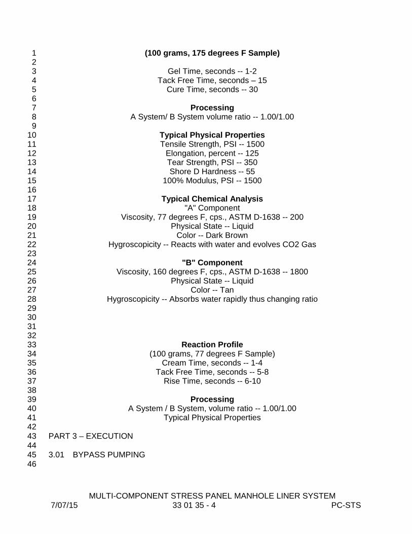
MULTI-COMPONENT STRESS PANEL MANHOLE LINER SYSTEM 7/07/15 33 01 35 - 4 PC-STS
(100 grams, 175 degrees F Sample) 1 2
Gel Time, seconds -- 1-2 3 Tack Free Time, seconds – 15 4
Cure Time, seconds -- 30 5 6
Processing 7 A System/ B System volume ratio -- 1.00/1.00 8
9 Typical Physical Properties 10 Tensile Strength, PSI -- 1500 11
Elongation, percent -- 125 12 Tear Strength, PSI -- 350 13 Shore D Hardness -- 55 14
100% Modulus, PSI -- 1500 15 16
Typical Chemical Analysis 17 "A" Component 18
Viscosity, 77 degrees F, cps., ASTM D-1638 -- 200 19 Physical State -- Liquid 20
Color -- Dark Brown 21 Hygroscopicity -- Reacts with water and evolves CO2 Gas 22
23 "B" Component 24
Viscosity, 160 degrees F, cps., ASTM D-1638 -- 1800 25 Physical State -- Liquid 26
Color -- Tan 27 Hygroscopicity -- Absorbs water rapidly thus changing ratio 28
29 30 31 32
Reaction Profile 33 (100 grams, 77 degrees F Sample) 34
Cream Time, seconds -- 1-4 35 Tack Free Time, seconds -- 5-8 36
Rise Time, seconds -- 6-10 37 38
Processing 39 A System / B System, volume ratio -- 1.00/1.00 40
Typical Physical Properties 41 42 PART 3 – EXECUTION 43 44 3.01 BYPASS PUMPING 45 46

MULTI-COMPONENT STRESS PANEL MANHOLE LINER SYSTEM 7/07/15 33 01 35 - 5 PC-STS
A. Prior to conducting any work, Contractor is to establish an approved bypass 1 pumping system in accordance with these specifications and all local noise 2 ordinances. Submit plan for bypass and maintenance of traffic to the 3 Engineer for approval prior to conducting the Work. 4
5 3.02 SURFACE PREPARATION 6 7
A. Abrasive blasting equipment shall remove all deteriorated concrete, hard 8 contaminants, localized micro-organisms, gas contaminants, from the 9 concrete walls, floors or other structures. Final product shall be a cleaned, 10 exposed and virgin concrete aggregate ready for rehabilitation material. 11
12 B. After completion of surface preparation, blasting phase, perform the seven 13
point check list, which is the inspection for: 14 15 1. Leaks 16 2. Cracks 17 3. Holes 18 4. Exposed rebar 19 5. Ring and Cover Condition 20 6. Invert Condition 21 7. Inlet and Outlet Pipe Condition 22 23
C. After the defects in the structure are identified, repair all leaks with a chemical 24 or hydraulic sealant designed for use in field sealing of ground water. Severe 25 cracks shall be "repaired using a urethane based chemical" sealant. Product 26 to be utilized shall be as approved by County/Engineer prior to installation. 27 Repairs to exposed rebar, defective pipe penetrations or inverts, etc. shall be 28 repaired utilizing non-shrink grout or approved alternative method. 29
30 D. Prior to application of final liner application, if required, reblast the entire 31
structure and remove all abrasive materials. 32 33 3.03 MATERIAL INSTALLATION 34 35
A. The limits of the corrosion protection system shall be all exposed interior to 36 end at the drywell hatch opening concrete surfaces including walls, tap 37 sections, risers, etc., unless otherwise directed by the County/Engineer. 38
39 B. Application of multi-component system shall be in strict accordance with 40
manufacturer's recommendation. Final installation shall be a minimum 41 thickness of 500 mils. A permanent identification number and date of work 42 performed shall be affixed to the structure in a readily visible location. 43
44 C. Provide final written report to County/Engineer detailing the location, date of 45
report, and description of repair. 46

MULTI-COMPONENT STRESS PANEL MANHOLE LINER SYSTEM 7/07/15 33 01 35 - 6 PC-STS
1 3.04 INSPECTION 2 3
A. Final concrete structure corrosion protection system shall be completely free 4 of pinholes or voids. Entire exposed concrete surface shall be protected with 5 corrosion protection system. Liner thickness shall be the minimum value as 6 described here and shown on the project drawings. 7
8 3.05 REPAIRS OF DEFECTS 9 10
A. All defects identified during inspection such as pinholes, low film mileage, etc. 11 shall be repaired with same material. 12
13 END OF SECTION 14

URETHANE/EPOXY, POLYUREA MANHOLE LINER SYSTEM 7/07/15 33 01 36 - 1 PC-STS
SECTION 33 01 36 1 2
URETHANE/ EPOXY, POLYUREA MANHOLE LINER SYSTEM 3 4
PART 1 - GENERAL 5 6 1.01 SCOPE OF WORK 7 8
A. The Work described within details a complete program for application of 9 urethane/epoxy, polyurea liner system coating to manholes, wet wells, 10 junction chamber, or other concrete structures. The completed system will 11 provide a corrosion resistant liner to prevent deterioration from hydrogen 12 sulfide and other corrosive gases/acids within the wastewater stream. 13
14 1.02 SUBMITTALS 15 16
A: All materials and procedures required to establish compliance with the 17 Specifications shall be submitted to the County/Engineer for 18 review/approval. 19
20 B. Submittals shall include at least the following: 21
22 1. Descriptive literature, bulletins and/or catalogs of materials. 23 24 2. Work procedures including flow diversion plan, method of repair, 25
etc. 26 27 3. Materials and method for repair of leaks or cracks in concrete 28
structure. 29 30 4. Final installation report on completed structures. 31
32 1.03 WARRANTY 33 34
A. Manufacturer shall warrant all coatings against failure for a period of ten (10) 35 years, performing repairs to the damage and restore the coating at no cost to 36 the County within sixty (60) days after written notification of the failure. 37
38 1.04 QUALITY ASSURANCE 39 40
A. The manufacturer and/or installer of the total liner system of concrete 41 structures shall be a company that specializes in the design, manufacture or 42 installation of corrosion protection systems for concrete structures including 43 manholes, wet wells, junction chambers, etc. Installer shall be completely 44 trained in leak repair, surface preparation and corrosion material application 45 on concrete structures. Corrosion materials/products shall be suitable for 46

URETHANE/EPOXY, POLYUREA MANHOLE LINER SYSTEM 7/07/15 33 01 36 - 2 PC-STS
installation in a severe hydrogen sulfide environment without any deterioration 1 to the liner and shall completely prevent the breakdown of concrete surfaces. 2
3 B. To ensure total unit responsibility, all materials and installation thereof shall 4
be furnished and coordinated with/by one supplier/installer who turnkeys the 5 Work and assumes full responsibility for entire operation. 6
7 C. Urethane/Epoxy, Polyurea Liner System shall be as specified in Material 8
Specification Manual. 9 10 1.05 SUBSTITUTIONS 11 12
A. Only after execution of the contract will Engineer consider requests from 13 Contractor for substitutions. Substitutions will be considered only when a 14 product becomes unavailable due to no fault of Contractor. 15
16 B. Items identified as “equal” shall be accompanied by product literature and 17
a written itemized comparison of the published specifications (feature by 18 feature from the manufacturer’s literature) for the item specified and for 19 the item proposed. The burden of proof of “equality” shall be on the 20 supplier. 21
22 C. Request constitutes a representation that Contractor: 23
1. Has investigated proposed product and determined that it meets or 24 exceeds, in all respects, specified product. 25
2. Will provide the same warranty for substitution as for specified 26 product. 27
3. Will coordinate installation and make other changes which may be 28 required for Work to be complete in all respects. 29
4. Waives claims for additional costs which may subsequently 30 become apparent. 31
32 D. Substitutions will not be considered when they are indicated or implied on 33
shop drawing or product data submittals without separate written request, 34 or when acceptance will require substantial revision of Contract 35 Documents. 36
37 E. Engineer will determine acceptability of proposed substitution, and will 38
notify Contractor of acceptance or rejection in writing within a reasonable 39 time. 40
41 PART II – PRODUCTS 42
43 2.01 MATERIALS AND EQUIPMENT 44 45
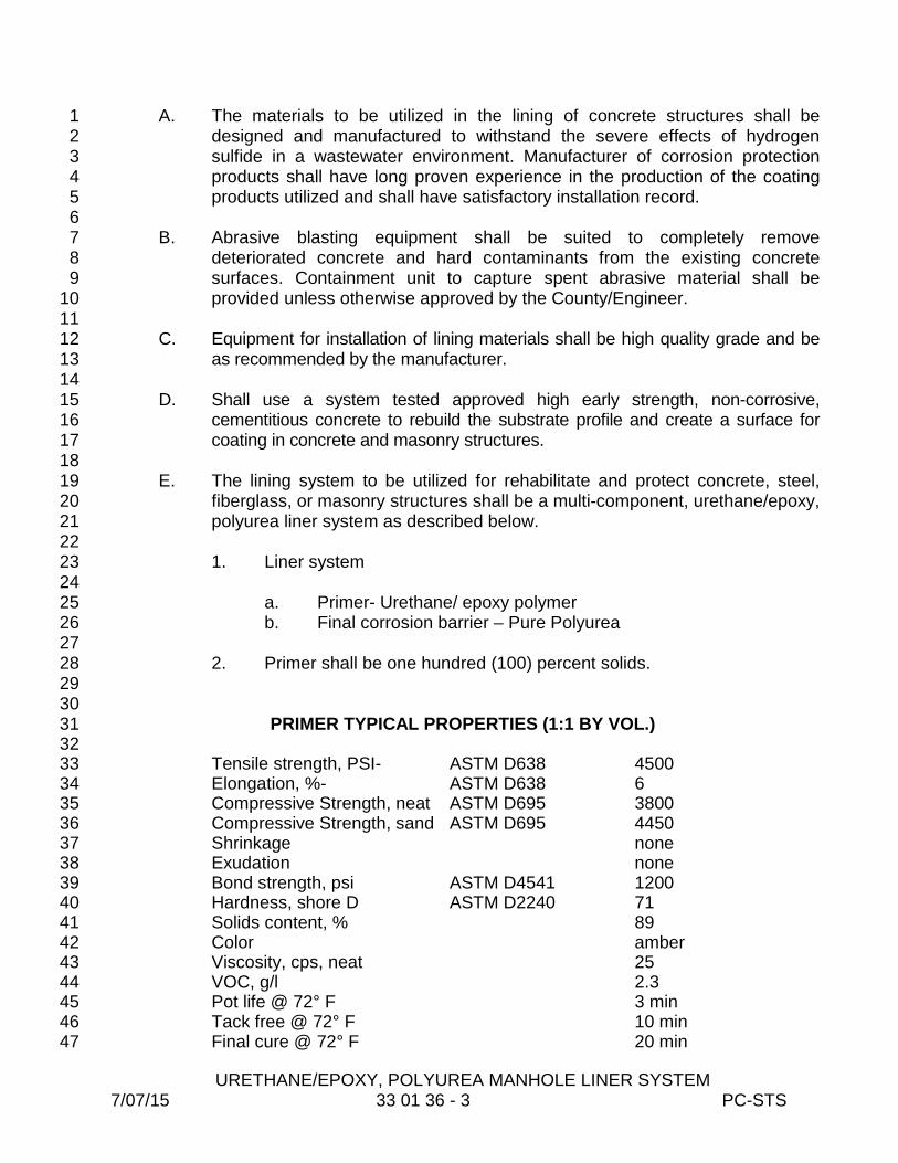
URETHANE/EPOXY, POLYUREA MANHOLE LINER SYSTEM 7/07/15 33 01 36 - 3 PC-STS
A. The materials to be utilized in the lining of concrete structures shall be 1 designed and manufactured to withstand the severe effects of hydrogen 2 sulfide in a wastewater environment. Manufacturer of corrosion protection 3 products shall have long proven experience in the production of the coating 4 products utilized and shall have satisfactory installation record. 5
6 B. Abrasive blasting equipment shall be suited to completely remove 7
deteriorated concrete and hard contaminants from the existing concrete 8 surfaces. Containment unit to capture spent abrasive material shall be 9 provided unless otherwise approved by the County/Engineer. 10
11 C. Equipment for installation of lining materials shall be high quality grade and be 12
as recommended by the manufacturer. 13 14 D. Shall use a system tested approved high early strength, non-corrosive, 15
cementitious concrete to rebuild the substrate profile and create a surface for 16 coating in concrete and masonry structures. 17
18 E. The lining system to be utilized for rehabilitate and protect concrete, steel, 19
fiberglass, or masonry structures shall be a multi-component, urethane/epoxy, 20 polyurea liner system as described below. 21
22 1. Liner system 23
24 a. Primer- Urethane/ epoxy polymer 25 b. Final corrosion barrier – Pure Polyurea 26
27 2. Primer shall be one hundred (100) percent solids. 28
29 30
PRIMER TYPICAL PROPERTIES (1:1 BY VOL.) 31 32
Tensile strength, PSI- ASTM D638 4500 33 Elongation, %- ASTM D638 6 34 Compressive Strength, neat ASTM D695 3800 35 Compressive Strength, sand ASTM D695 4450 36 Shrinkage none 37 Exudation none 38 Bond strength, psi ASTM D4541 1200 39 Hardness, shore D ASTM D2240 71 40 Solids content, % 89 41 Color amber 42 Viscosity, cps, neat 25 43 VOC, g/l 2.3 44 Pot life @ 72° F 3 min 45 Tack free @ 72° F 10 min 46 Final cure @ 72° F 20 min 47
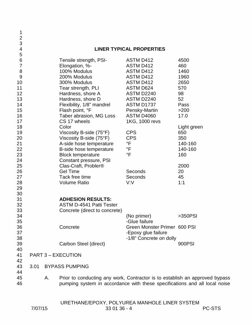
URETHANE/EPOXY, POLYUREA MANHOLE LINER SYSTEM 7/07/15 33 01 36 - 4 PC-STS
1 2 3
LINER TYPICAL PROPERTIES 4 5
Tensile strength, PSI- ASTM D412 4500 6 Elongation, %- ASTM D412 460 7 100% Modulus ASTM D412 1460 8 200% Modulus ASTM D412 1960 9 300% Modulus ASTM D412 2650 10 Tear strength, PLI ASTM D624 570 11 Hardness, shore A ASTM D2240 98 12 Hardness, shore D ASTM D2240 52 13 Flexibility, 1/8” mandrel ASTM D1737 Pass 14 Flash point, °F Pensky-Martin >200 15 Taber abrasion, MG Loss ASTM D4060 17.0 16 CS 17 wheels 1KG, 1000 revs 17 Color Light green 18 Viscosity B-side (75°F) CPS 650 19 Viscosity B-side (75°F) CPS 350 20 A-side hose temperature °F 140-160 21 B-side hose temperature °F 140-160 22 Block temperature °F 160 23 Constant pressure, PSI 24 Clas-Craft, Probler® 2000 25 Gel Time Seconds 20 26 Tack free time Seconds 45 27 Volume Ratio V:V 1:1 28 29 30 ADHESION RESULTS: 31 ASTM D-4541 Patti Tester 32 Concrete (direct to concrete) 33 (No primer) >350PSI 34 -Glue failure 35 Concrete Green Monster Primer 600 PSI 36 -Epoxy glue failure 37 -1/8” Concrete on dolly 38 Carbon Steel (direct) 900PSI 39
40 PART 3 – EXECUTION 41 42 3.01 BYPASS PUMPING 43 44
A. Prior to conducting any work, Contractor is to establish an approved bypass 45 pumping system in accordance with these specifications and all local noise 46

URETHANE/EPOXY, POLYUREA MANHOLE LINER SYSTEM 7/07/15 33 01 36 - 5 PC-STS
ordinances. Submit plan for bypass and maintenance of traffic to the 1 Engineer for approval prior to conducting the Work. 2
3 4
3.02 SURFACE PREPARATION 5 6
A. Abrasive blasting equipment shall remove all deteriorated concrete, hard 7 contaminants, localized micro-organisms, and gas contaminants, from the 8 walls, ceiling, benches, floors, pipes or other structures. Final product shall be 9 a cleaned, exposed and virgin concrete aggregate ready for rehabilitation 10 material. 11
12 B. After completion of surface preparation, blasting phase, perform the seven 13
point check list, which is the inspection for: 14 15 1. Leaks 16 2. Cracks 17 3. Holes 18 4. Exposed rebar 19 5. Ring and Cover Condition 20 6. Invert Condition 21 7. Inlet and Outlet Pipe Condition 22 23
C. After the defects in the structure are identified, repair all leaks with a chemical 24 or hydraulic sealant designed for use in field sealing of ground water. Severe 25 cracks shall be "repaired using a urethane based chemical" sealant. Product 26 to be utilized shall be as approved by County/Engineer prior to installation. 27 Repairs to exposed rebar, defective pipe penetrations or inverts, etc. shall be 28 repaired utilizing non-shrink grout or approved alternative method. 29
30 D. Prior to application of final liner application, if required, reblast the entire 31
structure and remove all abrasive materials. 32 33 3.03 MATERIAL INSTALLATION 34 35
A. The limits of the corrosion protection system shall be all exposed interior to 36 end at the drywell hatch opening concrete surfaces including walls, tap 37 sections, risers, etc., unless otherwise directed by the County/Engineer. 38
39 B. Application of multi-component system shall be in strict accordance with 40
manufacturer's recommendation. Final installation shall be a minimum 41 thickness of 90 mils to an unlimited build thickness. 42
43 C. Provide final written report to County/Engineer detailing the location, date of 44
report, and description of repair. 45 46
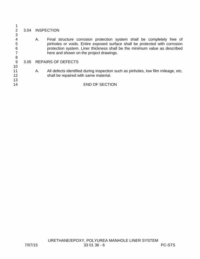
URETHANE/EPOXY, POLYUREA MANHOLE LINER SYSTEM 7/07/15 33 01 36 - 6 PC-STS
1 3.04 INSPECTION 2 3
A. Final structure corrosion protection system shall be completely free of 4 pinholes or voids. Entire exposed surface shall be protected with corrosion 5 protection system. Liner thickness shall be the minimum value as described 6 here and shown on the project drawings. 7
8 3.05 REPAIRS OF DEFECTS 9 10
A. All defects identified during inspection such as pinholes, low film mileage, etc. 11 shall be repaired with same material. 12
13 END OF SECTION 14

POLYURETHANE MANHOLE LINER SYSTEM 7/07/15 33 01 37 - 1 PC-STS
SECTION 33 01 37 1 2
POLYURETHANE MANHOLE LINER SYSTEM 3 4
PART 1 - GENERAL 5 6 1.01 SCOPE OF WORK 7 8
A. The Work described within details a complete program for application of 9 polyurethane liner system coating to manholes, wet wells, junction chamber, 10 or other concrete structures. The completed system will provide a waterproof, 11 corrosion resistant liner to prevent deterioration from hydrogen sulfide and 12 other corrosive gases/acids within the wastewater stream. This liner system 13 shall restore structural integrity (over 500,000 psi flexural modulus) of brick/ 14 concrete structures 15
16 1.02 SUBMITTALS 17 18
A: All materials and procedures required to establish compliance with the 19 Specifications shall be submitted to the County/Engineer for 20 review/approval. 21
22 B. Submittals shall include at least the following: 23
24 1. Descriptive literature, bulletins and/or catalogs of materials. 25 26 2. Work procedures including flow diversion plan, method of repair, 27
etc. 28 29 3. Materials and method for repair of leaks or cracks in concrete 30
structure. 31 32 4. Final installation report on completed structures. 33
34 1.03 WARRANTY 35 36
A. Manufacturer shall warrant all coatings against failure for a minimum period of 37 ten (10) years, performing repairs to the damage and restore the coating at 38 no cost to the County within sixty (60) days after written notification of the 39 failure. 40
41 1.04 QUALITY ASSURANCE 42 43
A. The manufacturer and/or installer of the total liner system of concrete 44 structures shall be a company that specializes in the design, manufacture or 45 installation of corrosion protection systems for concrete structures including 46

POLYURETHANE MANHOLE LINER SYSTEM 7/07/15 33 01 37 - 2 PC-STS
manholes, wet wells, junction chambers, etc. Installer shall be completely 1 trained in leak repair, surface preparation and corrosion material application 2 on concrete structures. Corrosion materials/products shall be suitable for 3 installation in a severe hydrogen sulfide environment without any deterioration 4 to the liner and shall completely prevent the breakdown of concrete surfaces. 5
6 B. To ensure total unit responsibility, all materials and installation thereof shall 7
be furnished and coordinated with/by one supplier/installer who turnkeys the 8 Work and assumes full responsibility for entire operation. 9
10 C. Polyurethane liner system shall be as specified in Materials Specifications 11
Manual, 12 13
1.05 SUBSTITUTIONS 14 15
A. Only after execution of the contract will Engineer consider requests from 16 Contractor for substitutions. Substitutions will be considered only when a 17 product becomes unavailable due to no fault of Contractor. 18
19 B. Items identified as “equal” shall be accompanied by product literature and 20
a written itemized comparison of the published specifications (feature by 21 feature from the manufacturer’s literature) for the item specified and for 22 the item proposed. The burden of proof of “equality” shall be on the 23 supplier. 24
25 C. Request constitutes a representation that Contractor: 26
1. Has investigated proposed product and determined that it meets or 27 exceeds, in all respects, specified product. 28
2. Will provide the same warranty for substitution as for specified 29 product. 30
3. Will coordinate installation and make other changes which may be 31 required for Work to be complete in all respects. 32
4. Waives claims for additional costs which may subsequently 33 become apparent. 34
35 D. Substitutions will not be considered when they are indicated or implied on 36
shop drawing or product data submittals without separate written request, 37 or when acceptance will require substantial revision of Contract 38 Documents. 39
40 E. Engineer will determine acceptability of proposed substitution, and will 41
notify Contractor of acceptance or rejection in writing within a reasonable 42 time. 43
44 PART II – PRODUCTS 45
46
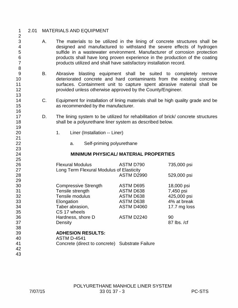
POLYURETHANE MANHOLE LINER SYSTEM 7/07/15 33 01 37 - 3 PC-STS
2.01 MATERIALS AND EQUIPMENT 1 2
A. The materials to be utilized in the lining of concrete structures shall be 3 designed and manufactured to withstand the severe effects of hydrogen 4 sulfide in a wastewater environment. Manufacturer of corrosion protection 5 products shall have long proven experience in the production of the coating 6 products utilized and shall have satisfactory installation record. 7
8 B. Abrasive blasting equipment shall be suited to completely remove 9
deteriorated concrete and hard contaminants from the existing concrete 10 surfaces. Containment unit to capture spent abrasive material shall be 11 provided unless otherwise approved by the County/Engineer. 12
13 C. Equipment for installation of lining materials shall be high quality grade and be 14
as recommended by the manufacturer. 15 16 D. The lining system to be utilized for rehabilitation of brick/ concrete structures 17
shall be a polyurethane liner system as described below. 18 19
1. Liner (Installation -- Liner) 20 21
a. Self-priming polyurethane 22 23
MINIMUM PHYSICAL/ MATERIAL PROPERTIES 24 25
Flexural Modulus ASTM D790 735,000 psi 26 Long Term Flexural Modulus of Elasticity 27
ASTM D2990 529,000 psi 28 29 Compressive Strength ASTM D695 18,000 psi 30 Tensile strength ASTM D638 7,450 psi 31 Tensile modulus ASTM D638 425,000 psi 32 Elongation ASTM D638 4% at break 33 Taber abrasion, ASTM D4060 17.7 mg loss 34 CS 17 wheels 35 Hardness, shore D ASTM D2240 90 36 Density 87 lbs. /cf 37 38 ADHESION RESULTS: 39 ASTM D-4541 40 Concrete (direct to concrete) Substrate Failure 41
42 43
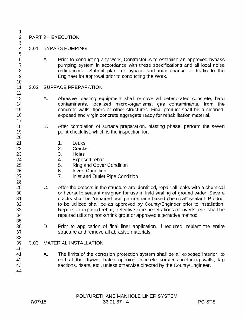
POLYURETHANE MANHOLE LINER SYSTEM 7/07/15 33 01 37 - 4 PC-STS
1 PART 3 – EXECUTION 2 3 3.01 BYPASS PUMPING 4 5
A. Prior to conducting any work, Contractor is to establish an approved bypass 6 pumping system in accordance with these specifications and all local noise 7 ordinances. Submit plan for bypass and maintenance of traffic to the 8 Engineer for approval prior to conducting the Work. 9
10 3.02 SURFACE PREPARATION 11 12
A. Abrasive blasting equipment shall remove all deteriorated concrete, hard 13 contaminants, localized micro-organisms, gas contaminants, from the 14 concrete walls, floors or other structures. Final product shall be a cleaned, 15 exposed and virgin concrete aggregate ready for rehabilitation material. 16
17 B. After completion of surface preparation, blasting phase, perform the seven 18
point check list, which is the inspection for: 19 20 1. Leaks 21 2. Cracks 22 3. Holes 23 4. Exposed rebar 24 5. Ring and Cover Condition 25 6. Invert Condition 26 7. Inlet and Outlet Pipe Condition 27 28
C. After the defects in the structure are identified, repair all leaks with a chemical 29 or hydraulic sealant designed for use in field sealing of ground water. Severe 30 cracks shall be "repaired using a urethane based chemical" sealant. Product 31 to be utilized shall be as approved by County/Engineer prior to installation. 32 Repairs to exposed rebar, defective pipe penetrations or inverts, etc. shall be 33 repaired utilizing non-shrink grout or approved alternative method. 34
35 D. Prior to application of final liner application, if required, reblast the entire 36
structure and remove all abrasive materials. 37 38 3.03 MATERIAL INSTALLATION 39 40
A. The limits of the corrosion protection system shall be all exposed interior to 41 end at the drywell hatch opening concrete surfaces including walls, tap 42 sections, risers, etc., unless otherwise directed by the County/Engineer. 43
44

POLYURETHANE MANHOLE LINER SYSTEM 7/07/15 33 01 37 - 5 PC-STS
B. Application of polyurethane liner system shall be in strict accordance with 1 manufacturer's recommendation. Final installation shall be a minimum 2 thickness of 250 mils and not more than 500 mils. 3
4 C. Provide final written report to County/Engineer detailing the location, date of 5
report, and description of repair. 6 7 3.04 INSPECTION 8 9
A. Final concrete structure corrosion protection system shall be completely free 10 of pinholes or voids. Entire exposed concrete surface shall be protected with 11 corrosion protection system. Liner thickness shall be the minimum value as 12 described here and shown on the project drawings. 13
14 3.05 REPAIRS OF DEFECTS 15 16
A. All defects identified during inspection such as pinholes, low film mileage, etc. 17 shall be repaired with same material. 18
19 END OF SECTION 20

POLYMORPHIC RESIN MANHOLE LINER SYSTEM 7/07/15 33 01 38 - 1 PC-STS
SECTION 33 01 38 1 2
POLYMORPHIC RESIN MANHOLE LINER SYSTEM 3 4
PART 1 - GENERAL 5 6 1.01 SCOPE OF WORK 7 8
A. The Work described within details a complete program for application of 9 polymorphic resin liner system coating to manholes, wet wells, junction 10 chamber, or other concrete structures. The completed system will provide a 11 waterproof, corrosion resistant liner to prevent deterioration from hydrogen 12 sulfide and other corrosive gases/acids within the wastewater stream. This 13 liner system shall restore structural integrity (over 500,000 psi flexural 14 modulus) of brick/ concrete structures 15
16 1.02 SUBMITTALS 17 18
A: All materials and procedures required to establish compliance with the 19 Specifications shall be submitted to the County/Engineer for 20 review/approval. 21
22 B. Submittals shall include at least the following: 23
24 1. Descriptive literature, bulletins and/or catalogs of materials. 25 26 2. Work procedures including flow diversion plan, method of repair, 27
etc. 28 29 3. Materials and method for repair of leaks or cracks in concrete 30
structure. 31 32 4. Final installation report on completed structures. 33
34 1.03 WARRANTY 35 36
A. Manufacturer shall warrant all coatings against failure for a minimum period of 37 ten (10) years, performing repairs to the damage and restore the coating at 38 no cost to the County within sixty (60) days after written notification of the 39 failure. 40
41 1.04 QUALITY ASSURANCE 42 43
A. The manufacturer and/or installer of the total liner system of concrete 44 structures shall be a company that specializes in the design, manufacture or 45 installation of corrosion protection systems for concrete structures including 46
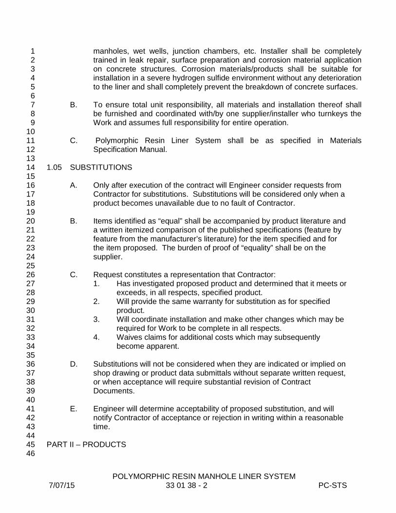
POLYMORPHIC RESIN MANHOLE LINER SYSTEM 7/07/15 33 01 38 - 2 PC-STS
manholes, wet wells, junction chambers, etc. Installer shall be completely 1 trained in leak repair, surface preparation and corrosion material application 2 on concrete structures. Corrosion materials/products shall be suitable for 3 installation in a severe hydrogen sulfide environment without any deterioration 4 to the liner and shall completely prevent the breakdown of concrete surfaces. 5
6 B. To ensure total unit responsibility, all materials and installation thereof shall 7
be furnished and coordinated with/by one supplier/installer who turnkeys the 8 Work and assumes full responsibility for entire operation. 9
10 C. Polymorphic Resin Liner System shall be as specified in Materials 11
Specification Manual. 12 13
1.05 SUBSTITUTIONS 14 15
A. Only after execution of the contract will Engineer consider requests from 16 Contractor for substitutions. Substitutions will be considered only when a 17 product becomes unavailable due to no fault of Contractor. 18
19 B. Items identified as “equal” shall be accompanied by product literature and 20
a written itemized comparison of the published specifications (feature by 21 feature from the manufacturer’s literature) for the item specified and for 22 the item proposed. The burden of proof of “equality” shall be on the 23 supplier. 24
25 C. Request constitutes a representation that Contractor: 26
1. Has investigated proposed product and determined that it meets or 27 exceeds, in all respects, specified product. 28
2. Will provide the same warranty for substitution as for specified 29 product. 30
3. Will coordinate installation and make other changes which may be 31 required for Work to be complete in all respects. 32
4. Waives claims for additional costs which may subsequently 33 become apparent. 34
35 D. Substitutions will not be considered when they are indicated or implied on 36
shop drawing or product data submittals without separate written request, 37 or when acceptance will require substantial revision of Contract 38 Documents. 39
40 E. Engineer will determine acceptability of proposed substitution, and will 41
notify Contractor of acceptance or rejection in writing within a reasonable 42 time. 43
44 PART II – PRODUCTS 45
46
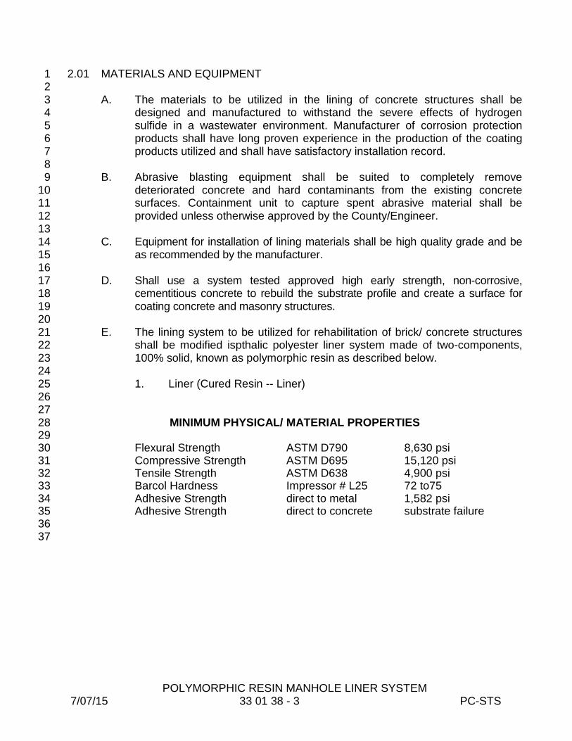
POLYMORPHIC RESIN MANHOLE LINER SYSTEM 7/07/15 33 01 38 - 3 PC-STS
2.01 MATERIALS AND EQUIPMENT 1 2
A. The materials to be utilized in the lining of concrete structures shall be 3 designed and manufactured to withstand the severe effects of hydrogen 4 sulfide in a wastewater environment. Manufacturer of corrosion protection 5 products shall have long proven experience in the production of the coating 6 products utilized and shall have satisfactory installation record. 7
8 B. Abrasive blasting equipment shall be suited to completely remove 9
deteriorated concrete and hard contaminants from the existing concrete 10 surfaces. Containment unit to capture spent abrasive material shall be 11 provided unless otherwise approved by the County/Engineer. 12
13 C. Equipment for installation of lining materials shall be high quality grade and be 14
as recommended by the manufacturer. 15 16 D. Shall use a system tested approved high early strength, non-corrosive, 17
cementitious concrete to rebuild the substrate profile and create a surface for 18 coating concrete and masonry structures. 19
20 E. The lining system to be utilized for rehabilitation of brick/ concrete structures 21
shall be modified ispthalic polyester liner system made of two-components, 22 100% solid, known as polymorphic resin as described below. 23
24 1. Liner (Cured Resin -- Liner) 25
26 27
MINIMUM PHYSICAL/ MATERIAL PROPERTIES 28 29
Flexural Strength ASTM D790 8,630 psi 30 Compressive Strength ASTM D695 15,120 psi 31 Tensile Strength ASTM D638 4,900 psi 32 Barcol Hardness Impressor # L25 72 to75 33 Adhesive Strength direct to metal 1,582 psi 34 Adhesive Strength direct to concrete substrate failure 35
36 37

POLYMORPHIC RESIN MANHOLE LINER SYSTEM 7/07/15 33 01 38 - 4 PC-STS
1 PART 3 – EXECUTION 2 3 3.01 BYPASS PUMPING 4 5
A. Prior to conducting any work, Contractor is to establish an approved bypass 6 pumping system in accordance with these specifications and all local noise 7 ordinances. Submit plan for bypass and maintenance of traffic to the 8 Engineer for approval prior to conducting the Work. 9
10 3.02 SURFACE PREPARATION 11 12
A. Abrasive blasting equipment shall remove all deteriorated concrete, hard 13 contaminants, localized micro-organisms, gas contaminants, from the 14 concrete walls, floors or other structures. Final product shall be a cleaned, 15 exposed and virgin concrete aggregate ready for rehabilitation material. 16
17 B. After completion of surface preparation, blasting phase, perform the seven 18
point check list, which is the inspection for: 19 20 1. Leaks 21 2. Cracks 22 3. Holes 23 4. Exposed rebar 24 5. Ring and Cover Condition 25 6. Invert Condition 26 7. Inlet and Outlet Pipe Condition 27 28
C. After the defects in the structure are identified, repair all leaks with a chemical 29 or hydraulic sealant designed for use in field sealing of ground water. Severe 30 cracks shall be "repaired using a polyurethane based chemical" sealant. 31 Product to be utilized shall be as approved by County/Engineer prior to 32 installation. Repairs to exposed rebar, defective pipe penetrations or inverts, 33 etc. shall be repaired utilizing non-shrink grout or approved alternative 34 method. 35
36 D. Prior to application of final liner application, if required, reblast the entire 37
structure and remove all abrasive materials. 38 39 3.03 MATERIAL INSTALLATION 40 41
A. The limits of the corrosion protection system shall be all exposed interior 42 surfaces, from the invert to the manhole cover opening, all concrete surfaces 43 including walls, top sections, risers, etc., unless otherwise directed by the 44 County/Engineer. 45
46
POLYMORPHIC RESIN MANHOLE LINER SYSTEM 7/07/15 33 01 38 - 5 PC-STS
B. Application of polymorphic resin liner system shall be in strict accordance with 1 manufacturer's recommendation. The three coat system is made of a prime 2 coat (DS-101 10- 25 mils thick), intermediate coat (DS-301 75- 150 mils 3 thick), and a final coat (DS-401 10- 25 mils thick). Final installation shall be a 4 minimum thickness of 150 mils and not more than 250 mils thick. 5
6 C. Provide final written report to County/Engineer detailing the location, date of 7
report, and description of repair. 8 9 3.04 INSPECTION 10 11
A. Final concrete structure corrosion protection system shall be completely free 12 of pinholes or voids. Entire exposed concrete surface shall be protected with 13 corrosion protection system. Liner thickness shall be the minimum value as 14 described here and shown on the project drawings. 15
16 3.05 REPAIRS OF DEFECTS 17 18
A. All defects identified during inspection such as pinholes, low film mileage, etc. 19 shall be repaired with same material. 20
21 END OF SECTION 22
CALCIUM ALUMINATE MANHOLE LINER SYSTEM 8/24/15 33 01 39 - 1 PC-STS
SECTION 33 01 39 1 2
CALCIUM ALUMINATE MANHOLE LINER SYSTEM 3 4
PART 1 - GENERAL 5 6 1.01 SCOPE OF WORK 7 8
A. The Work described within details a complete program for application of 9 calcium aluminate liner system coating to manholes, wet wells, junction 10 chamber, or other concrete structures. The completed system will provide a 11 corrosion resistant liner to prevent deterioration from hydrogen sulfide and 12 other corrosive gases/acids within the wastewater stream. 13
14 1.02 SUBMITTALS 15 16
A: All materials and procedures required to establish compliance with the 17 Specifications shall be submitted to the County/Engineer for 18 review/approval. 19
20 B. Submittals shall include at least the following: 21
22 1. Descriptive literature, bulletins and/or catalogs of materials. 23 24 2. Work procedures including flow diversion plan, method of repair, 25
etc. 26 27 3. Materials and method for repair of leaks or cracks in concrete 28
structure. 29 30 4. Final installation report on completed structures. 31
32 1.03 WARRANTY 33 34
A. Manufacturer shall warrant all coatings against failure for a period of ten (10) 35 years, performing repairs to the damage and restore the coating at no cost to 36 the County within sixty (60) days after written notification of the failure. 37
38 1.04 QUALITY ASSURANCE 39 40
A. The manufacturer and/or installer of the total liner system of concrete 41 structures shall be a company that specializes in the design, manufacture or 42 installation of corrosion protection systems for concrete structures including 43 manholes, wet wells, junction chambers, etc. Installer shall be completely 44 trained in leak repair, surface preparation and corrosion material application 45 on concrete structures. Corrosion materials/products shall be suitable for 46
CALCIUM ALUMINATE MANHOLE LINER SYSTEM 8/24/15 33 01 39 - 2 PC-STS
installation in a severe hydrogen sulfide environment without any deterioration 1 to the liner and shall completely prevent the breakdown of concrete surfaces. 2
3 B. To ensure total unit responsibility, all materials and installation thereof shall 4
be furnished and coordinated with/by one supplier/installer who turnkeys the 5 Work and assumes full responsibility for entire operation. 6
7 C. Calcium Aluminate liner system shall be as specified in Materials 8
Specification Manual. 9 10 1.05 SUBSTITUTIONS 11 12
A. Only after execution of the contract with Pinellas County will Engineer 13 consider requests from Contractor for substitutions. Substitutions will be 14 considered only when a product becomes unavailable due to no fault of 15 Contractor. 16
17 B. Items identified as “equal” shall be accompanied by product literature and 18
a written itemized comparison of the published specifications (feature by 19 feature from the manufacturer’s literature) for the item specified and for 20 the item proposed. The burden of proof of “equality” shall be on the 21 supplier. 22
23 C. Request constitutes a representation that Contractor: 24
1. Has investigated proposed product and determined that it meets or 25 exceeds, in all respects, specified product. 26
2. Will provide the same warranty for substitution as for specified 27 product. 28
3. Will coordinate installation and make other changes which may be 29 required for Work to be complete in all respects. 30
4. Waives claims for additional costs which may subsequently 31 become apparent. 32
33 D. Substitutions will not be considered when they are indicated or implied on 34
shop drawing or product data submittals without separate written request, 35 or when acceptance will require substantial revision of the Contract 36 Documents. 37
38 E. Engineer will determine acceptability of proposed substitution, and will 39
notify Contractor of acceptance or rejection in writing within a reasonable 40 time. 41
42 PART II – PRODUCTS 43
44 2.01 MATERIALS AND EQUIPMENT 45 46
CALCIUM ALUMINATE MANHOLE LINER SYSTEM 8/24/15 33 01 39 - 3 PC-STS
A. The materials to be utilized in the lining of concrete structures shall be 1 designed and manufactured to withstand the severe effects of hydrogen 2 sulfide in a wastewater environment. Manufacturer of corrosion protection 3 products shall have long proven experience in the production of the coating 4 products utilized and shall have satisfactory installation record. 5
6 B. Abrasive blasting equipment shall be suited to completely remove 7
deteriorated concrete and hard contaminants from the existing concrete 8 surfaces. Containment unit to capture spent abrasive material shall be 9 provided unless otherwise approved by the County/Engineer. 10
11 C. Equipment for installation of lining materials shall be high quality grade and be 12
as recommended by the manufacturer. 13 14 D. As required, contractor shall use a system tested approved high early strength, 15
non-corrosive, cementitious concrete to rebuild the substrate profile and create 16 a surface for coating concrete and masonry structures. 17
18 E. The lining system to be utilized shall be a calcium aluminate liner system as 19
described below. 20 21
1. Shall be 100% calcium aluminate cement with 100% calcium aluminate 22 aggregate. 23 24
2. The chemical composition of the cement portion as well as the aggregates 25 of the mortar mix shall be as follows: 26
27 Al2O3 41%-46% 28 CaO 33%-38% 29 FeO+Fe2O3 8%-13% 30 SiO2 4%-9% 31
32 3. The design properties of the mortar mix shall be as follows: 33
34 24 HRS 7 DAYS 28 DAYS 35 ASTM C 109 Compressive Strength, psi >5,500 >7,000 >8,000 36 ASTM C 293 Flexural Strength, psi >1,300 >1,400 >1,600 37 ASTM C 596 Shrinkage at 90% Humidity, % < 0.04 < 0.06 < 0.08 38 ASTM C 666 Freeze-Thaw After 300 Cycles No Damage 39 ASTM C 496 Splitting Tensile Strength > 900 psi 40 ASTM C 882 Bond Strength by Slant Shear > 2,300 psi at 28 days 41 ASTM C 457 Air Void Content (7 Days) 2-4% 42 ASTM C 642 Specific Gravity/Absorption Test (7 Days) 3-5% 43 Static Modulus of Elasticity (24 hrs) 7.1 x 10⁶ psi 44
45 46 PART 3 – EXECUTION 47 48

CALCIUM ALUMINATE MANHOLE LINER SYSTEM 8/24/15 33 01 39 - 4 PC-STS
3.01 BYPASS PUMPING 1 2
A. Prior to conducting any work, Contractor is to establish an approved bypass 3 pumping system in accordance with these specifications and all local noise 4 ordinances. Submit plan for bypass and maintenance of traffic to the 5 Engineer for approval prior to conducting the Work. 6
7 3.02 SURFACE PREPARATION 8 9
A. Abrasive blasting equipment shall remove all deteriorated concrete, hard 10 contaminants, localized micro-organisms, gas contaminants, from the 11 concrete walls, floors or other structures. Final product shall be a cleaned, 12 exposed and virgin concrete aggregate ready for rehabilitation material. 13
14 B. After completion of surface preparation, blasting phase, perform the seven 15
point check list, which is the inspection for: 16 17 1. Leaks 18 2. Cracks 19 3. Holes 20 4. Exposed rebar 21 5. Ring and Cover Condition 22 6. Invert Condition 23 7. Inlet and Outlet Pipe Condition 24 25
C. After the defects in the structure are identified, repair all leaks with a chemical 26 or hydraulic sealant designed for use in field sealing of ground water. Severe 27 cracks shall be "repaired using a urethane based chemical" sealant. Product 28 to be utilized shall be as approved by County/Engineer prior to installation. 29 Repairs to exposed rebar, defective pipe penetrations or inverts, etc. shall be 30 repaired utilizing non-shrink grout or approved alternative method. 31
32 D. Prior to application of final liner application, if required, reblast the entire 33
structure and remove all abrasive materials. 34 35 3.03 MATERIAL INSTALLATION 36 37
A. The limits of the corrosion protection system shall be all exposed interior 38 surfaces, from the invert to the manhole cover opening, including walls, top 39 sections, risers, etc., unless otherwise directed by the County/Engineer. 40
41 B. Application of calcium aluminate lining system shall be in strict accordance 42
with manufacturer's recommendation. Final installation shall be a minimum 43 thickness as recommended by manufacturer. A permanent identification 44 number and date of work performed shall be affixed to the structure in a 45 readily visible location. 46
CALCIUM ALUMINATE MANHOLE LINER SYSTEM 8/24/15 33 01 39 - 5 PC-STS
1 C. Provide final written report to County/Engineer detailing the location, date of 2
report, and description of repair. 3 4 3.04 INSPECTION 5 6
A. Final concrete structure corrosion protection system shall be completely free 7 of pinholes or voids. Entire exposed concrete surface shall be protected with 8 corrosion protection system. Liner thickness shall be the minimum value as 9 described here and shown on the project drawings. 10
11 3.05 REPAIRS OF DEFECTS 12 13
A. All defects identified during inspection shall be repaired with same material. 14 15
END OF SECTION 16

CIP STRUCTURAL LATERAL CONNECTION LINING
33 01 40-1 7/07/15 PC - STS
SECTION 33 01 40 1 2
CIPP STRUCTURAL LATERAL CONNECTION LINING 3 4 5
7 PART 1 -- GENERAL 6
1.01 SCOPE 8 9
A. The work specified in this section consists of providing for the reconstruction of a 10 particular mainline section and the adjacent lateral sewer pipe without excavation 11 while providing a structural one piece leak free connection at the interface of the 12 mainline and lateral pipelines. 13
14 B. Pipelines to be rehabilitated may be in backyard easements, light traffic subdivision 15
roadways or highways requiring Maintenance of Traffic plans conforming to Florida 16 Department of Transportation and Pinellas County requirements. No additional 17 compensation will be made for these locations unless specified within the Contract 18
19 C. It shall be assumed that pipelines to be rehabilitated will only need light cleaning 20
and sewage bypass pumping to successfully install the liner system. If the 21 Contractor feels point repairs are necessary to complete lining of a particular lateral 22 line segment, the County will make the individual necessary repair or cancel that 23 section of Work at no cost to the County. The Contractor shall be responsible for all 24 material removed from the sewer and shall properly dispose of materials in 25 accordance with the appropriate regulatory agency requirements. 26
27 1.02 GENERAL 28 29
A. The reconstruction will be accomplished using a non-woven fabric tube of particular 30 length and a thermoset resin with physical and chemical properties appropriate for 31 the application. The lateral tube within a translucent inversion bladder is vacuum 32 impregnated with the resin then placed inside a protective carrying device. The 33 mainline liner that is physically attached to the lateral tube is affixed around a rigid 34 launching device. The launching device and protective carrying device are winched 35 into the existing sewer. When the launching device is properly positioned at the 36 lateral connection, the mainline liner is inflated and the resin saturated tube is 37 inverted up through the lateral pipe, using air or water pressure, by the action of the 38 inversion bladder. Once the tube/resin composite is cured, the inversion bladder 39 and launching/carrying devices are removed. 40
41 B. The cured-in-place mainline/lateral connection repair system shall be as specified in 42
Materials Specification Manual, or as otherwise specified by County Engineer. 43 44

CIP STRUCTURAL LATERAL CONNECTION LINING
33 01 40-2 7/07/15 PC - STS
1.03 SUBMITTALS 1 2
A. The CONTRACTOR shall submit shop drawings, samples of materials, and other 3 information to the OWNER for review. Included shall be design calculations for the 4 work. 5
6 1.04 QUALIFICATIONS 7 8
A. The Qualifications of the CONTRACTOR shall be submitted with the bid. The 9 Contractor is defined as the entity that holds the contracting license (“the state or 10 county licensed company”) to perform contracting work under these bid documents, 11 the Contractor Qualifications must be submitted in this name. Individual 12 qualifications will not be considered in the product experience. These Qualifications 13 shall include detailed descriptions of the following: 14
1. Name, business address and telephone number of the CONTRACTOR. 15
2. Name(s) of all supervisory personnel to be directly involved with this project. 16
3. Specialty technicians shall be certified by the proposed product manufacturer 17 and/or its authorized representative. Certifications shall be submitted to the 18 OWNER. 19
4. The CONTRACTOR shall provide the references of previous project lists 20 going back five years including his customer’s names, city contact name, 21 phone number, city project number, city project name. The list must include 22 the number of laterals rehabilitated as well as the number and type of 23 connection seals installed. If there have been any changes in the materials it 24 shall be brought to the attention of the OWNER and is to be noted on the 25 submitted projects used for references showing the date and type of the 26 changes. 27
5. To be acceptable, the installer (the company bidding) must have a minimum 28 of 1,500 full circle structural connection installations of the specific product 29 bid, which must be documented, in Florida. 30
6. To be acceptable, the installer (the company bidding) must have applicable 31 experience in the commercial installation of the product bid. 32
33
35 PART 2 -- PRODUCTS 34
2.01 GENERAL 36 37
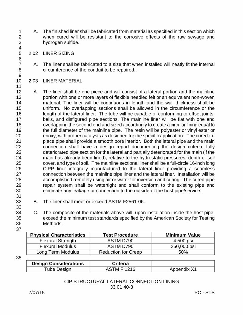
CIP STRUCTURAL LATERAL CONNECTION LINING
33 01 40-3 7/07/15 PC - STS
A. The finished liner shall be fabricated from material as specified in this section which 1 when cured will be resistant to the corrosive effects of the raw sewage and 2 hydrogen sulfide. 3
4 2.02 LINER SIZING 5 6
A. The liner shall be fabricated to a size that when installed will neatly fit the internal 7 circumference of the conduit to be repaired.. 8
9 2.03 LINER MATERIAL 10
11 A. The liner shall be one piece and will consist of a lateral portion and the mainline 12
portion with one or more layers of flexible needled felt or an equivalent non-woven 13 material. The liner will be continuous in length and the wall thickness shall be 14 uniform. No overlapping sections shall be allowed in the circumference or the 15 length of the lateral liner. The tube will be capable of conforming to offset joints, 16 bells, and disfigured pipe sections. The mainline liner will be flat with one end 17 overlapping the second end and sized accordingly to create a circular lining equal to 18 the full diameter of the mainline pipe. The resin will be polyester or vinyl ester or 19 epoxy, with proper catalysts as designed for the specific application. The cured-in-20 place pipe shall provide a smooth bore interior. Both the lateral pipe and the main 21 connection shall have a design report documenting the design criteria, fully 22 deteriorated pipe section for the lateral and partially deteriorated for the main (if the 23 main has already been lined), relative to the hydrostatic pressures, depth of soil 24 cover, and type of soil. The mainline sectional liner shall be a full-circle 16-inch long 25 CIPP liner integrally manufactured to the lateral liner providing a seamless 26 connection between the mainline pipe liner and the lateral liner. Installation will be 27 accomplished remotely using air or water for inversion and curing. The cured pipe 28 repair system shall be watertight and shall conform to the existing pipe and 29 eliminate any leakage or connection to the outside of the host pipe/service. 30
31 B. The liner shall meet or exceed ASTM F2561-06. 32
33 C. The composite of the materials above will, upon installation inside the host pipe, 34
exceed the minimum test standards specified by the American Society for Testing 35 Methods. 36
37 Physical Characteristics Test Procedure Minimum Value
Flexural Strength ASTM D790 4,500 psi Flexural Modulus ASTM D790 250,000 psi
Long Term Modulus Reduction for Creep 50% 38
Design Considerations Criteria Tube Design ASTM F 1216 Appendix X1

CIP STRUCTURAL LATERAL CONNECTION LINING
33 01 40-4 7/07/15 PC - STS
Hydrostatic Buckling ASTM F 1216 Appendix X1 1
The CIPP design for the lateral tube and mainline structural connection shall 2 assume no bonding to the original host pipe. 3
4 2.04 LINER DESIGN 5
6 A. The minimum required structural CIPP wall thickness shall be based on the physical 7
properties described above and in accordance with the design equations in the 8 appendix of ASTM F 1216, and the following design parameters: 9
10 Design Safety Factor 2.0 Retention Factor for Long-Term Flexural Modulus to be used in Design
50 %
Ovality* 2 % Groundwater Depth = Pipe Depth (above invert)*
ft.
Soil Depth (above crown)* ft. Soil Modulus 700 psi Soil Density 120 pcf Live Load One H20 passing
truck Design Condition (lateral pipe) Fully deteriorated Design Condition (main pipe) Lined Main Pipe Partially deteriorated Design Condition (main pipe) Unlined Main Pipe
Fully deteriorated
*Denotes information which can be provided here or in inspection video tapes or project construction plans. Multiple line segments may require a table of values.
Note: There are two conditions that require design calculation in accordance 11 with ASTM F1216. 1) Lateral piping. 2) The connection in the main, lined or 12 unlined main. 13
14 B. The lining manufacturer shall submit to the OWNER for review complete design 15
calculations for the liner, both main connection and lateral pipe designs, signed and 16 sealed by a Professional Engineer registered in the State of Florida and certified by 17 the manufacturer as to the compliance of his materials to the values used in the 18 calculations. A safety factor of 2 shall be applied in the design calculation. The 19 lateral host pipe shall be considered fully deteriorated, the previously lined main 20 pipe shall be considered partially deteriorated. The liner shall be designed to 21 withstand a live load equivalent to one H-20 passing truck plus all pertinent dead 22 loads, hydrostatic pressure and grout pressure (if any). For design purposes, the 23 water table shall be considered at grade elevation. The liner shall be designed in 24 accordance with ASTM F 1216. The buckling analysis shall account for the 25

CIP STRUCTURAL LATERAL CONNECTION LINING
33 01 40-5 7/07/15 PC - STS
combination of dead load, live load, hydrostatic pressure and grout pressure (if any). 1 The liner side support shall be considered as if provided by soil pressure against 2 the liner. The existing lateral pipe shall not be considered as providing any 3 structural support. If the main pipe has been lined a partially deteriorated condition 4 is to be used for the design of the main. Hydrostatic loads must be considered in 5 three existing pipe conditions 1) mainline design, for previously lined mains and 2) 6 unlined mains as well as 3) the lateral pipe design for unlined pipe. Modulus of soil 7 reaction shall be 700, corresponding to a moderate degree of compaction of 8 bedding and a fine-grained soil as shown in AWWA Manual M45, Fiberglass Pipe 9 Design. 10 11
C. The design of the finished main / lateral connection liner shall include compression 12 gaskets at the termination points of the liner. When the hydrophilic gaskets come in 13 contact with water they swell to create a compression gasket fit between the host 14 pipe and the newly installed lateral connection. 15
16 Because of inconsistencies during application of, chemical grout, hydrophilic caulks 17 or hydrophilic paste, these sealing attempts are not an acceptable alternative. 18 Acceptable seals are Insignia™seals or approved equal. 19
20 D. Liner shall be neither accepted nor installed until design calculations are acceptable 21
to the OWNER for the three existing pipe conditions. 22 23 24
26 PART 3 -- EXECUTION 25
3.01 PUBLIC NOTIFICATION 27 28
A. All residences and businesses that may be affected by work performed in the 29 installation of CIP liners shall be notified by delivery of a notification. Notifications 30 are to be delivered at least 72 hours before any work commences at a site. 31
32 B. Notifications shall include the following: and explanation of the work to be 33
performed; when the work is anticipated to commence; where the work is to be 34 performed in reference to local streets; the name and office telephone numbers of 35 Contractor representatives; the nature of the inconvenience(s) anticipated to be 36 experienced by the resident/ business owner; the anticipated duration of the work; 37 that the work is being performed on behalf of Pinellas County; and a Pinellas 38 County contact and telephone number as provided by the County. 39
40 C. Information included in the notifications regarding Contractor representatives shall 41
include both the name and twenty-four (24) hour telephone number of the 42 Contractor’s supervisor at the work site(s) and the name and business telephone 43
CIP STRUCTURAL LATERAL CONNECTION LINING
33 01 40-6 7/07/15 PC - STS
number of a Contractor representative who is responsible for the administration of 1 the project from the location of the offices of the Contractor. 2
3 D. The proposed format of all correspondence from the Contractor, to the public, shall 4
be reviewed, and approved, by the Engineer or a Designee. 5 6
E. Complete public notification is to be the exclusive responsibility of the Contractor. 7 8
F. Cost associated with public notifications shall be included in the contract price of 9 CIPP installation. 10
11 3.02 WASTEWATER FLOW CONTROL 12 13
A. The Contractor shall bypass sewage around the section of pipe being lined. Bypass 14 shall be set up to cause minimum disruption to residents, commercial 15 establishments and traffic. 16
17
B. Where lines to be rehabilitated are determined by the Engineer to be of a critical 18 nature and cannot be bypassed during normal work hours, lining may have to be 19 scheduled at low flow during nighttime hours. 20
21
C. If wastewater flow is minimal and lining can be installed in a timely manner, bypass 22 may not be required. 23
24
D. The Contractor shall make every effort possible to notify each customer whose 25 service is affected by the lining operation. 26
27
E. The Contractor shall be responsible for any back-up or any damage caused by the 28 lining process. 29
30 3.03 PRE-CLEANING AND TELEVISION INSPECTION 31 32
A. The Contractor shall clean and televise the assigned gravity sewer to be 33 rehabilitated prior to construction in accordance with specification 33 01 32 - 34 Sanitary Sewer Cleaning and Televising. Only National Association of Sewer 35 Companies (NASSCO) Pipeline Assessment and Certification Program (PACP) 36 certified personnel trained in locating breaks, obstacles and service connections by 37 closed circuit television using NASSCO certified software shall perform the 38 inspection. The interior surface of the pipeline shall be cleaned with high pressure 39 water jet equipment prior to receiving the new liner. All service locations and 40 obstructions, such as dropped joints and protruding services, shall be noted on the 41 inspection. 42
CIP STRUCTURAL LATERAL CONNECTION LINING
33 01 40-7 7/07/15 PC - STS
1 B. Pre-Cleaning and television inspection to occur a minimum of five working days 2
prior to installation of the liner, or as otherwise directed by Engineer. 3 4
C. The Contractor shall notify the Engineer if any severe problems are discovered 5 during televising that would prohibit the installation of the liner. If conditions such as 6 broken pipe or major blockages are found that will prevent proper cleaning, or 7 where additional damage would occur if cleaning is attempted or continued, the 8 Contractor shall advise the Engineer. 9 10
D. The Contractor shall notify the Engineer if pipe joint offsets greater than 20% the 11 interior diameter of the pipe are present. No liners shall be installed through joints 12 offset greater than 20% the interior diameter of the pipe unless otherwise directed 13 by Engineer. 14
15
E. Any damage done by the Contractor to any existing sewer pipe or structure by the 16 Contractor will be immediately repaired to a condition equal to or better than its 17 original condition at the Contractor’s expense. 18
19
F. Cost associated with pre-televising and cleaning shall be included in the contract 20 price of CIPP installation. 21
22 23
24 3.04 LINER INSTALLATION 25 26
A. The tube is inspected for tears and frayed sections. The tube, in good condition, 27 will be vacuum impregnated with the thermostat resin. The resin will be introduced 28 into the tube creating a slug of resin at the beginning of the tube. A calibration roller 29 will assist the resin slug to move throughout the tube. All air in the tube shall be 30 removed by vacuum allowing the resin to thoroughly impregnate the tube. All resin 31 shall be contained to ensure no public property or persons are exposed to the liquid 32 resin. The mainline liner will be saturated upon a wet-out platform. The resin 33 impregnated sample (wick), shall be retained by the installer to provide verification 34 of the curing process taking place in the host pipe. 35
B. The saturated tube along with the inversion bladder will be inserted into the carrying 36 device. The mainline liner is affixed on the launching device. Both the launching 37 and carrying device is pulled into the pipe using a cable winch. The pull is complete 38 when the open port of the launching device is aligned with the interface of the 39 service connection and mainline pipe. The resin saturated lateral tube is completely 40 protected during the pull. No resin shall be lost by contact with manhole walls or the 41 pipe during the pull. The resin saturated mainline liner is supported upon the rigid 42
CIP STRUCTURAL LATERAL CONNECTION LINING
33 01 40-8 7/07/15 PC - STS
launcher that is elevated above the pipe invert by means of rotating skid system. 1 The mainline liner should not be contaminated or diluted by exposure to dirt, debris, 2 or water during the pull. 3
C. The installer shall document the placement of the liner by internal video inspection 4 with the camera being inserted from the lateral pipe down to the mainline pipe. 5
D. The mainline liner is expanded against the mainline pipe and lateral tube is inverted 6 out of the launcher/carrying device by controlled air or water pressure. The installer 7 shall be capable of viewing the lateral liner contacting the lateral pipe from the 8 beginning to the end of the repair. The mainline liner and the lateral tube are held 9 tightly in place against the wall of the host pipe by controlled pressure until the cure 10 is complete. 11
E. When the curing process is complete, the pressure will be released. The inversion 12 bladder and launching device shall be removed from the host pipe with the winch. 13 No barriers, coatings, or any material other than the cured tube/resin composite, 14 specifically designed for desirable physical and chemical resistance properties, 15 should ever be left in the host pipe. Any materials used in the installation other than 16 the cured tube/resin composite are to be removed from the pipe by the installer. 17
3.05 POST CLEANING AND TELEVISION INSPECTION 18 19
A. Post cleaning and television inspection shall occur only after all necessary work and 20 preparation has been completed, including the following: installation on CIP liner in 21 accordance with specifications, pre-installation cleaning and television inspection; 22 implementation of adequate flow control; and the placement of traffic control 23 measures in accordance with these specifications. 24
25
B. The Contractor shall clean and televise the assigned gravity sewer after 26 rehabilitation in accordance with specification 33 01 32- Sanitary Sewer Cleaning 27 and Televising. Only NASSCO PACP certified personnel trained in locating breaks, 28 obstacles and service connections by closed circuit television using PACP/ LACP 29 certified software shall perform the inspection. The interior surface of the pipeline 30 shall be cleaned with high pressure water jet equipment immediately prior to 31 conducting the post television inspection. All gouges, cracks, bumps, bulges and 32 obstructions, such as dropped joints, shall be noted on the inspection. 33
34
C. In the case of bellies in the line, the pipe shall be cleared of any standing water to 35 provide continuous visibility during the post inspection. 36
37

CIP STRUCTURAL LATERAL CONNECTION LINING
33 01 40-9 7/07/15 PC - STS
D. The Contractor shall provide all inspections in digital PACP/ LACP format including 1 printed inspection logs. All lateral inspections shall, at a minimum, be compatible 2 with Granite XP currently used by the County. 3
4
E. Cost associated with post-televising and cleaning shall be included in the contract 5 price of CIPP installation. 6
7
3.06 ACCEPTANCE AND TESTING 8 9
A. The finished liner shall be continuous over the entire length of the installation. The 10 liner shall be free from visual defects, damage, deflection, holes, delamination, 11 uncured resin, and the like. There shall be no visible infiltration through the liner or 12 from behind the liner. 13
B. Verification of a non-leaking lateral liner and service connection shall require an air 14 test in accordance with the following specifications. Testing shall be performed at 15 the OWNER’S discretion. The cost for the test shall be included in the liner 16 installation cost, and no separate payment shall be made. 17
1. A camera shall be inserted into the lateral pipe via a clean-out upstream of 18 the upper most portion of the cured in-place lateral liner. The camera is then 19 moved through the lateral pipe until it becomes positioned at the lateral/main 20 connection. The camera is utilized to assist in positioning and placing a pair 21 of plugs in the mainline on either side of the lateral opening. A test device 22 with a minimum of a ten-inch clear separation shall be centered on the lateral 23 opening and spanning the brim of the lined connection. 24
2. Next, an air test plug shall be introduced into the lateral pipe. The test plug 25 will be placed inside of the cured in-place lateral liner at its upper most 26 portion. The test plug shall be inflated and sealed against the cured in-place 27 lateral liner at the upstream end of the liner. 28
3. The testing device within the mainline are then inflated and sealed across the 29 service connection. 30
4. Air-pressure not less than 4 PSI shall be introduced through the test plug. 31 The void area between the three plugs shall be pressurized at 4 PSI, held for 32 2 minutes and during this time the pressure shall not drop below 3.0 PSI. 33
5. If an installed cured in-place lateral liner fails the specified air test, the 34 following corrective measures shall be taken. 35
a. The cured in-place lateral liner shall be re-inspected by use of a 36 closed circuit television camera in attempt to identify the defect. 37
CIP STRUCTURAL LATERAL CONNECTION LINING
33 01 40-10 7/07/15 PC - STS
b. Any repairs made shall consist of materials that are structural and 1 meet or exceed the same criteria as the cured in-place lateral liner is 2 required to meet in a domestic sewer collection system. Such 3 materials shall have a minimum life expectancy of 50 years in 4 accordance with ASTM F-1216 (most recent standard) Appendix X1 5 Design Considerations and Appendix X2 Chemical-Resistance Test. 6
c. Once the defect has been corrected, the renewed lateral pipe shall be 7 re-tested in accordance with the air test procedure as described 8 above. 9
d. Any corrective measures shall be performed at the CONTRACTOR’s 10 expense. 11
6. If any of the air tests fail, the OWNER at its option may require the 12 CONTRACTOR to test an additional lateral at no additional charge to the 13 OWNER. If a second air test shall fail, the OWNER at its option may require 14 the CONTRACTOR to test additional or all of the installed cured in-place 15 lateral linings at no additional charge to the OWNER. 16
C. Each individual location contained in a Work Order is to be considered an 17 “individual project” such that all work, including all deliverables shall be reviewed 18 and accepted prior to the County accepting and processing payment for that 19 individual project. No partial payments will be made on individual projects. 20 21
3.07 CLEANUP 22 23
A. After the liner installation has been completed and accepted, the CONTRACTOR 24 shall clean up the entire project area and return the ground cover to grade. All 25 excess material and debris not incorporated into the permanent installation shall be 26 disposed of by the CONTRACTOR. 27
28 END OF SECTION 29
30 31
JACKING AND BORING 7/07/15 33 05 20 - 1 PC-STS
SECTION 33 05 20 1 2
JACKING AND BORING 3 4 PART 1 - GENERAL 5 6
A. Special crossings shall be constructed in accordance with the details shown 7 on the plans, or as directed. All materials and workmanship shall be as 8 specified, herein. 9
10 B. The Contractor is responsible for verifying the location of all utilities in the 11
ground before commencing the jack and bore operation. No 12 compensation will be allowed for labor or materials for unused casing. 13 The Contractor will be responsible for all damage incurred to roadways or 14 utilities by his operation. 15
16 PART 2 - PRODUCTS 17
18 2.01 CASINGS 19 20
A. All casings shall be installed accurately to line and grade and shall meet all 21 requirements of the prevailing rights-of-way holder. Casings shall be new 22 and of domestic material and manufacture. 23
24 B. Pipe casing shall be welded steel. The pipe casing shall be steel and 25
conform to the requirements of AWWA Standard C-200 and ASTM A-139, 26 Grade B. The pipe shall be coated internally and externally with coal-tar 27 primer followed by a hot coal-tar enamel in accordance with AWWA 28 Standard C-203. 29
30 C. Joints shall be full penetration butt welded in accordance with the 31
requirements of AWWA Standard C-206. The joints shall be double groove 32 welded with continuous circumferential welds and field lined and coated in 33 accordance with AWWA C-203. 34
35 D. All casings shall be in conformance with the specifications as shown on the 36
plans and detail sheets. 37 38
2.02 CARRIER PIPE 39 40 A. All carrier pipe shall be Class 50 ductile iron pipe with joint restraints or fully 41
restrained PVC pipe. 42 43
44

JACKING AND BORING 7/07/15 33 05 20 - 2 PC-STS
2.03 CASING SPACERS 1 2
A. The carrier pipe shall be installed in the casing on spacer skids. Casing 3 spacer skids shall be as specified in the Material Specification Manual. The 4 supports shall be dimensioned to center the carrier pipe in the casing with a 5 top clearance of one-half inch. The height of the supports and runners 6 combined shall be sufficient to provide not less than three-quarter inch 7 between the casing pipe and outside diameter of the carrier pipe joints. 8
9 B. Adequate casing spacers shall be provided to properly support the carrier 10
pipe and maintain pipe deflection within the pipe manufacturer’s 11 requirements. In any case, not less than three spacers for each individual 12 length of carrier pipe shall be provided. 13
14 2.04 TUNNEL LINER PLATES 15 16
A. Tunnel liner plates shall be asphalt coated galvanized steel plates. The 17 Contractor shall submit plans signed and sealed by a registered Engineer 18 in the State of Florida and written installation procedures with his request 19 for approval. 20
21 2.05 MATERIAL MANUFACTURERS 22 23
A. All materials shall be per Pinellas County Utility Material Specifications 24 Manual. 25
26 PART 3 – EXECUTION 27
28 3.01 CONSTRUCTION 29
30 A. Tunneling for the installation of large carrier pipe may be substituted for 31
jacking and boring when approved by the Engineer. 32 33
B. The casing pipe shall be installed by jacking and/or boring, to the length 34 shown on the plans through which the pipe provided is to be laid to the 35 required line and grade as shown on the plans, and extreme care shall be 36 taken to keep the jacking pipe to accurate line and grade. 37
38 C. All surfaces shall be smooth and uniform without bulges, dents, or warping 39
of lengths, and only new pipe shall be used. Finished lengths of pipe shall 40 be furnished with beveled cut ends to facilitate proper welding of 41 transverse joints. The diameter and wall thickness of the pipe shown on 42 the drawings is the minimum required and no extra compensation shall be 43 claimed by the Contractor if a larger and thicker pipe is used. It will be the 44 Contractor's responsibility in the event that the casing does buckle or 45 collapse during these operations. 46
JACKING AND BORING 7/07/15 33 05 20 - 3 PC-STS
D. The installation of the casing and boring at the head of the casing shall be 1 one simultaneously. Track guides of sufficient length to carry the power 2 unit and pipe installation shall be used, in order to maintain proper line and 3 grade of the casing. Surplus and unsuitable excavated material shall be 4 disposed of by the Contractor. 5
6 E. The jacking and exit pits shall have adequate backing provided for the 7
jacks in such a manner as to avoid any disturbance of adjacent structures 8 or utilities. The Contractor shall use sheeting for jacking and exit pits if the 9 angle of repose is exceeded or if by excavating for the pits results in 10 undermining nearby structures. The sheeting shall be cut three feet below 11 finished grade and left in place within the right-of-way if it is used. The 12 Contractor shall install adequate protective railing or temporary fences 13 around the pits within the crossing right-of-way at all times during 14 construction. 15
16 17
END OF SECTION 18
HORIZONTAL DIRECTIONAL DRILLING STANDARD SMALL DIAMETER INSTALLATIONS
7/07/15 33 05 21 - 1 PC-STS
SECTION 33 05 21 1 2
HORIZONTAL DIRECTIONAL DRILLING 3 4
STANDARD SMALL DIAMETER INSTALLATIONS 5 6
PART 1 - GENERAL 7 8 9 10 1.01 SCOPE OF WORK 11 12
A. The Work specified in this section consists of furnishing and installing 13 underground utilities using the horizontal directional drilling (HDD) method of 14 installation, also commonly referred to as directional boring or guided 15 horizontal boring. This Work shall include all services, equipment, materials, 16 and labor for the complete and proper installation, testing, restoration of 17 underground utilities and environmental protection and restoration. 18
19 B. Small Diameter Installation shall be defined as a HDD that the nominal 20 outside diameter of the product pipe is twelve (12) inches or less. 21
22 1.02 SUBMITTALS 23 24
A. Prior to beginning work, the Contractor must submit to the Engineer a Work 25 plan detailing the procedure and schedule to be used to execute the Project. 26 The Work plan should include a description of all equipment to be used, 27 down-hole tools, a list of personnel and their qualifications and experience 28 (including back-up personnel in the event that an individual is unavailable), 29 list of subcontractors, a schedule of work activity, a safety plan (including 30 MSDS of any potentially hazardous substances to be used), traffic control 31 plan (if applicable), an environmental protection plan and contingency plans 32 for possible problems. Work plan should be comprehensive, realistic and 33 based on actual working conditions for this particular Project. Plan should 34 document the thoughtful planning required to successfully complete the 35 Project. 36
37 B. The Contractor shall submit documentation that the proposed electrofusion 38
personnel have been certified by the pipe or electrofusion accessory 39 manufacturer. 40
41 C. All drilling fluids and loose cuttings shall be contained. No fluids shall be 42
allowed to enter any unapproved areas or natural waterways. Upon 43 completion of the directional drill project, all excess drilling fluid and material 44 shall be removed by the Contractor. 45

HORIZONTAL DIRECTIONAL DRILLING STANDARD SMALL DIAMETER INSTALLATIONS
7/07/15 33 05 21 - 2 PC-STS
1 D. The Contractor shall submit a Bentonite Management Plan that includes the 2
following as a minimum. 3 4
1. Rapid response procedures - directional drilling shall be performed by 5 a Contractor who has the expertise required to perform the related 6 work. The Contractor shall designate qualified personnel and 7 equipment on the site during directional drilling operations responsible 8 for monitoring drilling fluid pressure, and watching surface conditions 9 for visual signs of frac-out. Contractor shall provide immediate 10 response and initiate containment procedures in the event of an 11 occurrence of a bentonite spill. In the event of a bentonite spill or 12 frac-out all drilling activities shall be stopped. Drill stem shall be 13 removed from the bore hole and the hole abandoned. 14
15 2. Containment procedures - sediment control systems such as: silt 16
fence or earth berms on uplands, and floating silt barriers or other 17 aquatic barriers in water, and other means necessary to prevent the 18 spread of the bentonite spill shall be installed immediately. 19
20 3. Timely cleanup capability - remediation of the lost bentonite shall 21
begin immediately. Cleanup shall include removal of the material 22 from the site by an approved method, and disposal of the material by 23 an approved method in an appropriate location as directed by the 24 County representative. 25
26 E. Contractor shall submit Specifications on directional drilling equipment to be 27
used to ensure that the equipment will be adequate to complete the Project. 28 Equipment shall include but not be limited to: drilling rig, mud system, mud 29 motors (if applicable), down-hole tools, guidance system and rig safety 30 systems. Calibration records for guidance equipment shall be included. 31 Specifications for any drilling fluid additives that Contractor intends to use or 32 might use will be submitted. 33
34 F. Specifications on material to be used shall be submitted to Engineer and 35
material shall include the pipe, fittings, drilling mud, drilling additives and any 36 other item which is to be an installed component of the Project or used 37 during construction. 38
39 1.03 QUALITY ASSURANCE 40 41
A. The requirements set forth in this Specification include a wide range of 42 procedural precautions necessary to insure that the very basic, essential 43 aspects of a proper directional bore installation are adequately controlled. 44 Strict adherence shall be required under specifically covered conditions 45

HORIZONTAL DIRECTIONAL DRILLING STANDARD SMALL DIAMETER INSTALLATIONS
7/07/15 33 05 21 - 3 PC-STS
outlined in this Specification. Adherence to the Specifications contained 1 herein, or the Engineer's approval of any aspect of any directional bore 2 operation covered by this Specification, shall in no way relieve the Contractor 3 of their ultimate responsibility for the satisfactory completion of the Work 4 authorized under the Contract. 5
6 B. Drilling Notes: The pipe shall be installed to the exact lines and grades 7
shown on the plans by a State of Florida licensed and bonded undergournd 8 utility Contractor, with minimum two years experience in Directional Drilling. 9
10 PART 2 - PRODUCTS 11 12 2.01 GENERAL 13 14
A. Directional drilling equipment shall consist of a directional drilling rig of 15 sufficient capacity to perform the bore and pullback the pipe, a drilling fluid 16 mixing, delivery system of sufficient capacity to successfully complete the 17 crossing, a guidance system to accurately guide boring operations and 18 trained and competent personnel to operate the system. All equipment shall 19 be in good, safe operating condition with sufficient supplies, materials and 20 spare parts on hand to maintain the system in good working order for the 21 duration of this Project. 22
23 2.02 PRODUCT PIPE, JOINTS AND FITTINGS 24 25
A. PIPE 26 27
1. All product pipe to be installed by the HDD operation will be High 28 Density Polyethylene (HDPE), Restrained Joint PVC or Restrained 29 Joint Ductile Iron pipe. 30
2. Refer to material specifications for material requirements. 31
3. Refer to piping sections of this specification for pipe handling 32 requirements. 33
34 B. FITTINGS 35
36 1. Refer to material specifications for material requirements. 37 38
C. DRILLING FLUID (MUD) SYSTEM 39 40 1. Drilling fluid shall be composed of a carrier fluid (water) and drilling 41
fluid additives (bentonite and/or polymers). Bentonite is a naturally 42 occurring clay mineral (montmorillinite) that forms a mud when mixed 43 with water. 44
45
HORIZONTAL DIRECTIONAL DRILLING STANDARD SMALL DIAMETER INSTALLATIONS
7/07/15 33 05 21 - 4 PC-STS
2. The composition of the drill fluid is determined by the results of 1 geological investigation executed in line with the framework of the 2 project planned before construction. 3
4 3. The principal functions of drilling fluids used in HDD are: 5 6
a. Transporting drill cuttings to the surface by suspending and 7 carrying them in the fluid stream flowing in the annulus 8 between the borehole wall and the drill 9 pipe/product. 10 11
b. Cleaning build-up on drill bits or reamer cutters by directing 12 fluid streams at the cutters. 13
14 c. Cooling the downhole tools and electronic equipment. 15 16 d. Lubricating to reduce the friction between the drill pipe/product 17
pipe and the borehole wall. 18 19 e. Stabilizing the borehole, especially in loose or soft soils by 20
building a low permeability filter cake, and exerting a positive 21 hydrostatic pressure against the borehole wall. The filter cake 22 along with positive hydrostatic pressure reduces collapse of 23 the borehole and prevents formation fluids (i.e. groundwater) 24 from flowing into the borehole or drilling fluids from exiting the 25 borehole into the formation (loss of circulation). 26 27
f. The Contractor shall provide hydraulic power to the borehole 28 with a downhole mud motor. 29
30 g. The following fluid properties are to be tested and considered 31
to assure compatibility between the drilling fluid mixture and 32 the native soil after proper identification and characterization. 33 These fluid properties are density, viscosity, pH – value, 34 circulation, volume and solid content. 35
36 h. The drilling fluid pressures and flow rates shall be continuously 37
monitored and recorded by the Contractor at the pump and 38 within the annular space within thirty (30) feet of the drilling 39 head. 40
41 2.03 DRILLING SYSTEM 42 43
A. The directional drilling machine shall consist of a hydraulically powered 44 system to rotate, push and pull hollow drill pipe into the ground at a variable 45
HORIZONTAL DIRECTIONAL DRILLING STANDARD SMALL DIAMETER INSTALLATIONS
7/07/15 33 05 21 - 5 PC-STS
angle while delivering a pressurized fluid mixture to a guidable drill (bore) 1 head. The machine shall be anchored to the ground to withstand the pulling, 2 pushing and rotating pressure required to complete the crossing. The 3 hydraulic power system shall be self-contained with sufficient pressure and 4 volume to power drilling operations. Hydraulic system shall be free of leaks. 5 Rig shall have a system to monitor and record maximum pull-back pressure 6 during pull-back operations. The rig shall be grounded during drilling and 7 pull-back operations. There shall be a system to detect electrical current from 8 the drill string and an audible alarm which automatically sounds when an 9 electrical current is detected. 10
11 B. The drill head shall be steerable by changing its rotation and shall provide 12
the necessary cutting surfaces and drilling fluid jets. 13 14 C. Mud motors (if required) shall be of adequate power to turn the required 15
drilling tools. 16 17 D. The drill pipe shall be constructed of high quality 4130 seamless tubing, 18
grade D or better with thread. 19 20 2.04 GUIDANCE SYSTEM 21 22
A. The method of guidance utilized in locating and steering the pilot string from 23 entry to exit shall be state of the art. Readings shall be recorded after the 24 advancement of each successive drill pipe and the readings plotted. Access 25 to all recorded readings and plan and profile information shall be made 26 available to the Engineer, or his representative at all times. 27
28 2.05 DRILLING FLUID (MUD) SYSTEM 29 30
A. A self-contained, closed, drilling fluid mixing system shall be of sufficient size 31 to mix and deliver drilling fluid composed of bentonite clay, potable water and 32 appropriate additives. Mixing system shall be able to molecularly shear 33 individual bentonite particles from the dry powder to avoid clumping and 34 ensure thorough mixing. The drilling fluid reservoir tank shall be a minimum 35 of five hundred (500) gallons. Mixing system shall continually agitate the 36 drilling fluid during drilling operations. 37
38 B. Drilling fluid shall be composed of clean water and bentonite clay. Water 39
shall be from an authorized source with a pH of 8.5 - 10. Water of a lower pH 40 or with excessive calcium shall be treated with the appropriate amount of 41 sodium carbonate or equal. The water and bentonite clay shall be mixed 42 thoroughly and be free of any clumps or clods. No additional material may be 43 used in drilling fluid without prior approval from Engineer. Contractor is 44 responsible for provisions to obtain clean water for the fluid. 45

HORIZONTAL DIRECTIONAL DRILLING STANDARD SMALL DIAMETER INSTALLATIONS
7/07/15 33 05 21 - 6 PC-STS
The Bentonite mixture used shall have the minimum viscosities as measured 1 by a March Funnel: 2
3 Rock, Clay - 60 sec. 4 Hard Clay - 40 sec. 5 Soft Clay - 45 sec. 6 Sandy Clay - 90 sec. 7 8 Stable Sand - 80 sec. 9 Loose Sand - 110 sec. 10 Wet Sand - 110 sec. 11
12 These viscosities may be varied to best fit the soil conditions encountered, 13 as approved by the Engineer. 14
15 C. Additives to drilling fluid such as drill soap, polymers, etc. shall be 16
“environmentally safe” and be approved for such usage. No diesel fuel will 17 be used. 18
19 D. The mud pumping system shall have a minimum capacity of 50 GPM and be 20
capable of delivering the drilling fluid at a constant minimum pressure of 21 1000 psi. The delivery system shall have filters in-line to prevent solids from 22 being pumped into the drill pipe. Connections between the pump and drill 23 pipe shall be leak-free. Used drilling fluid and drilling fluid spilled during 24 drilling operations shall be contained and properly disposed of. A berm, or 25 equivalent, shall be maintained around drill rigs, drilling fluid mixing system, 26 entry and exit pits and drilling fluid recycling system to prevent spills into the 27 surrounding environment. Pumps and or vacuum truck(s) of sufficient size 28 shall be in place to convey excess drilling fluid from containment areas to 29 storage and facilities. 30
31 2.06 OTHER EQUIPMENT 32 33
A. Pipe rollers shall be of sufficient size to fully support the weight of the pipe 34 while being hydro-tested and during pull-back operations. Sufficient number 35 of rollers shall be used to prevent excess sagging of pipe. Rollers shall be 36 used as necessary to assist in pull back operations and in layout/fusing of 37 material. 38
39 B. Hydraulic or pneumatic pipe rammers may only be used if necessary and 40
with the authorization of Engineer. 41 42
C. Other devices or utility placement systems for providing horizontal thrust 43 other than those previously defined in the preceding sections shall not be 44 used unless approved by the Engineer prior to commencement of the Work. 45

HORIZONTAL DIRECTIONAL DRILLING STANDARD SMALL DIAMETER INSTALLATIONS
7/07/15 33 05 21 - 7 PC-STS
Consideration for approval will be made on an individual basis for each 1 specified location. The proposed device or system will be evaluated prior to 2 approval or rejection on its potential ability to complete the utility placement 3 satisfactorily without undue stoppage and to maintain line and grade within 4 the tolerances prescribed by the particular conditions of the Project. 5
6 PART 3 – EXECUTION 7 8 3.01 GENERAL 9 10
A. Contractor to contact Pinellas County Utilities at least forty-eight (48) hours 11 before each of the following activities: 1) the set up of a drilling pit, 2) the 12 start of drilling operation, 3) the installation of service pipe. Upon completion 13 of the pilot hole phase of the operation, a complete set of as-built records 14 shall be submitted in duplicate to the Engineer. These records shall include 15 copies of the plan and profile drawing, as well as directional readings 16 recorded during the drilling operation. 17
18 B. The drawings show existing utilities that are believed to be near the 19
directional drill alignment. There is no guarantee that these utilities are 20 located as shown or that other utilities may not be present. The Contractor is 21 to field locate existing utilities in advance of the work so as not to delay work 22 and avoid conflict or disruption of utility services. 23
24 C. 25
26 3.02 PERSONNEL REQUIREMENTS 27 28
A. All personnel shall be fully trained in their respective duties as part of the 29 directional drilling crew and in safety. Each person must have at least two 30 years directional drilling experience. A competent and experienced 31 supervisor representing the Contractor and Drilling Subcontractor shall be 32 present at all times during the actual drilling operations. A responsible 33 representative who is thoroughly familiar with the equipment and type work to 34 be performed, must be in direct charge and control of the operation at all 35 times. In all cases the supervisor must be continually present at the job site 36 during the actual directional bore operation. The Contractor and 37 Subcontractor shall have a sufficient number of competent workers on the 38 job at all times to insure the directional bore is made in a timely and 39 satisfactory manner. 40
41 Personnel who are unqualified, incompetent or otherwise not suitable for the 42 performance of this Project shall be removed from the jobsite and replaced 43 with a suitable person. 44
3.03 DRILLING PROCEDURE 45
HORIZONTAL DIRECTIONAL DRILLING STANDARD SMALL DIAMETER INSTALLATIONS
7/07/15 33 05 21 - 8 PC-STS
1 A. Work site as indicated on drawings, within right-of-way, shall be graded or 2
filled to provide a level working area. No alterations beyond what is required 3 for operations are to be made. Contractor shall confine all activities to 4 designated work areas. 5
6 B. Entire drill path shall be accurately surveyed with entry and exit stakes 7
placed in the appropriate locations within the areas indicated on Drawings. If 8 Contractor is using a magnetic guidance system, drill path will be surveyed 9 for any surface geo-magnetic variations or anomalies. 10
11 C. Contractor shall place silt fence between all drilling operations and any 12
drainage, wetland, waterway or other area designated for such protection by 13 contract documents, state, federal and local regulations. Additional 14 environmental protection necessary to contain any hydraulic or drilling fluid 15 spills shall be put in place, including berms, liners, turbidity curtains and other 16 measures. Contractor shall adhere to all applicable environmental 17 regulations. Fuel or oil may not be stored in bulk containers within two 18 hundred (200) feet of any water-body or wetland. 19
20 D. Contractor shall adhere to all applicable state, federal and local safety 21
regulations and all operations shall be conducted in a safe manner. Safety 22 meetings shall be conducted at least weekly with a written record of 23 attendance and topic submitted to Engineer. 24
25 E. Pipe shall be welded/fused together in one length, if space permits. Pipe will 26
be placed on pipe rollers before pulling into bore hole with rollers spaced 27 close enough to prevent excessive sagging of pipe. 28
29 F. Pilot hole shall be drilled on bore path with no deviations greater than five 30
percent of depth over a length of one hundred (100) feet. In the event that 31 pilot does deviate from bore path more than five percent of depth in one 32 hundred (100) feet, Contractor shall notify Engineer and Engineer may 33 require Contractor to pull-back and re-drill from the location along bore path 34 before the deviation. 35 36
G. In the event that a drilling fluid fracture, inadvertent returns or returns loss 37 occurs during pilot hole drilling operations, Contractor shall cease operations 38 and shall discuss corrective options with the Engineer, work shall then 39 proceed accordingly. 40
41 H. Upon approval of the pilot hole location by the Engineer, the hole 42
enlargening or back reaming phase of the installation shall begin. The 43 borehole diameter shall be increased to accommodate the pullback 44 operation of the required size of PE pipe. The type of back reamer to be 45
HORIZONTAL DIRECTIONAL DRILLING STANDARD SMALL DIAMETER INSTALLATIONS
7/07/15 33 05 21 - 9 PC-STS
utilized in this phase shall be determined by the types of subsurface soil 1 conditions that have been encountered during the pilot hole drilling operation. 2 The reamer type shall be at the Contractor's discretion with the final hole 3 diameter being a maximum of twenty (20) percent larger than the outside 4 diameter of the product pipe being installed in the borehole. 5
6 I. The open borehole may be stabilized by means of bentonite drilling slurry 7
pumped through the inside diameter of the drill pipe and through openings in 8 the reamer. The slurry will also serve as an agent to carry the loose cuttings 9 to the surface through the annulus of the borehole. These cuttings and 10 bentonite slurry are to be contained at the exit hole or entry side of the 11 directional bore in pits or holding tanks. The slurry may be recycled at this 12 time for reuse in the hole opening operation or it shall be hauled by the 13 Contractor to an approved dump site and properly disposed. A complete list 14 of all drilling fluid additives and mixtures to be used in the directional 15 operation will be submitted to the Engineer along with their respective 16 material safety data sheets. 17
18 J. In the event that pipe becomes stuck, Contractor shall notify Engineer. 19
Engineer, Contractor, and/or the maintaining agency shall discuss options 20 and then work will proceed accordingly. 21
22 K. Excess pipe shall be removed and the bore hole associated with this excess 23
pipe shall be filled with flowable fill or grout, unless the area of the excess 24 pipe is excavated and backfilled as part of the tie-in operations. 25
26 3.04 PIPE TESTING 27 28
A. Following successful pull-back of pipe, Contractor shall test pipe as required 29 in Section 01 45 17, Pipeline Testing Requirements. 30
31 3.05 SITE RESTORATION 32 33 A. Following drilling operations, Contractor will demobilize equipment and 34
restore the work-site to original condition. Any noticeable surface defects 35 due to the drilling operation shall be repaired by Contractor. 36
37 3.06 RECORD KEEPING 38 39
A. Contractor shall maintain a daily project log of drilling operations and a 40 guidance system log with a copy given to Engineer at completion of boring. 41 As-built drawings shall be certified as to accuracy by Contractor as required 42 in Section 01 78 39. 43
44 END OF SECTION 45

HORIZONTAL DIRECTIONAL DRILLING SUBAQUEOUS CROSSINGS AND LARGE DIAMETER INSTALLATIONS
7/07/15 33 05 22 - 1 PC-STS
SECTION 33 05 22 1 2
HORIZONTAL DIRECTIONAL DRILLING 3 4
SUBAQUEOUS CROSSINGS AND LARGE DIAMETER INSTALLATIONS 5 6 PART 1-GENERAL 7 8 1.01 DESCRIPTION OF REQUIREMENTS 9 10
A. This specification covers the installation of pipe by horizontal directional 11 drilling (HDD). HDD is a trenchless excavation method that is 12 accomplished in three phases. The first phase consists of drilling a small 13 diameter pilot hole along a designed directional path. The second phase 14 consists of enlarging the pilot hole to a diameter suitable for installation of 15 the pipe. The third phase consists of pulling the product pipe into the 16 enlarged hole. HDD is accomplished using a specialized horizontal drilling 17 rig with ancillary tools, equipment and borehole stabilizing drilling fluids. 18
19 B. The Contractor shall provide all necessary labor, tools, materials and 20
equipment to successfully complete the installation of directionally drilled 21 piping as specified herein and to the lines and grades shown on the 22 Contract Drawings. The Contractor shall be responsible for the final 23 constructed product, and for furnishing the qualified labor and 24 superintendence necessary for this method of construction. 25
26 C. The drilling operations shall use techniques of creating or directing a 27
borehole along a predetermined path to a specified target location. Use 28 of down-hole steering tools to change the boring course and monitoring 29 instrumentation to locate and orient the boring along a predetermined 30 course is required. 31
32 D. The mobile drilling system shall utilize a jetting drill bit and/or drill bit with 33
mud motor to drill and circulate cuttings and spoil from the borehole. 34 35 E. Steering shall be accomplished through the use of an articulated section 36
of drill collar that causes an angular offset resulting in the drill bit being off-37 center. When steering adjustments are required, as dictated by down hole 38 guidance monitoring equipment, the bit is rotated toward the desired 39 direction of travel and the drill pipe and bit are advanced forward without 40 rotation. 41
42 1.02 DEFINITIONS 43 44
A. Contractor’s Construction Drawings. Shall be defined as drawings by 45 which the Contractor proposes to construct, operate, build, etc., the 46

HORIZONTAL DIRECTIONAL DRILLING SUBAQUEOUS CROSSINGS AND LARGE DIAMETER INSTALLATIONS
7/07/15 33 05 22 - 2 PC-STS
referenced item. The submission of these drawings shall be required for 1 the sole purpose of providing sufficient details to verify that the 2 Contractor’s work progress is in accordance with the intent of the design. 3 When required, such drawings will have been previously reviewed and 4 sealed by a qualified professional engineer registered in the State of 5 Florida. 6
7 B. Subaqueous Crossings shall be defined as a HDD that crosses under a 8
body of water greater than 50 feet across. 9 10 C. Large Diameter Installation shall be defined as a HDD that the nominal 11
outside diameter of the product pipe is greater than twelve (12) inches. 12 13
1.03 REFERENCE SPECIFICATIONS, CODES, AND STANDARDS 14 15
A. American Association of State Highway and Transportation Officials 16 (AASHTO). 17
18 B. Occupational Safety and Health Administration (OSHA). 19
20 21 C. API Specifications 13A, 1993. Specification for Drilling Fluid Materials, 22
Fifteenth Edition, Dallas, Texas. American Petroleum Institute. 23 24 D. API Recommended Practice 13B-1, 1990. Standard Procedures for Field 25
Testing Water-Based Drilling Fluids, First Edition, Dallas, Texas, American 26 Petroleum Institute. 27
28 E. API Bulletin 13D, 1985. Bulletin on the Rheology of Oil-Well Drilling 29
Fluids, Second Edition, Dallas, Texas, American Petroleum Institute. 30 31 F. Horizontal Directional Drilling Good Practices Guidelines, HDD Industry 32
Consortium, 300pp, 2nd ed., 2004. 33 34 G. IADC Drilling Manual, 1992. Eleventh Edition, Houston, Texas, 35
International Association of Drilling Contractors. 36 37 H. Installation of Pipelines by Horizontal Directional Drilling, Pipeline 38
Research Committee, American Gas Association, PR-227-9424, April 39 1995. 40
41 I. Installation of Pipelines Beneath Levees Using Horizontal Directional 42
Drilling, US Army Corps of Engineers, Waterways Experiment Station, 43 Final Report, CPAR-GL-98-1, April 1998. 44
45
HORIZONTAL DIRECTIONAL DRILLING SUBAQUEOUS CROSSINGS AND LARGE DIAMETER INSTALLATIONS
7/07/15 33 05 22 - 3 PC-STS
J. Pressure Pipeline Design for Water and Wastewater, American Society for 1 Civil Engineers, 2nd ed., 1992 2
3 K. Tables for Hydraulic Design of Pipes and Sewers, American Society for 4
Civil Engineers, 5th ed., 1990. 5 6 1.04 SUBMITTALS 7
8 A. Prior to beginning the Work, the contractor must submit to the Engineer 9
the following items: 10 11
1. The Contractor shall provide a completed HDD Work plan with 12 drawings and written description identifying details of the proposed 13 method of construction and sequence of operations to be 14 performed during construction. The Work plan shall address the 15 following requirements: 16
17 18
a. Pre-construction walkover and site inspection. 19 20 1) Call- One Call for utilities location within the limits of 21
the HDD project (Ground Penetrating Radar (GPR) 22 Electronic Locate, Subsurface Location as required). 23
24 2) The Contractor shall video tape and take photographs 25
of near by structures which may be affected by 26 inadvertent fluid returns. 27
28 3) The Contractor shall review as-built drawing and prior 29
soil reports of past projects in the area, if available. 30 31 4) The Contractor shall make an effort to discuss the 32
scope of the proposed project with City, County and 33 State Agencies that may have previous project 34 construction knowledge in the vicinity. 35
36 b. The Contractor shall establish a drill profile between the 37
entry and exit point by observing various framework 38 conditions mentioned below in order to ensure, that the 39 intended theoretical drilling profile line can also be realized in 40 practice. 41 1) Entry and exit angle 42 43 2) Slant tangential sections 44 45 3) Radii of curvature 46
HORIZONTAL DIRECTIONAL DRILLING SUBAQUEOUS CROSSINGS AND LARGE DIAMETER INSTALLATIONS
7/07/15 33 05 22 - 4 PC-STS
1 4) Cover 2 3 5) Borehole diameter 4
5 If the Contractor is planning on deviating from bid document 6 HDD Profile, then the Contractor is required to submit 7 additional drawings with the new HDD Profile for the 8 engineer’s approval. 9 10 The deviation drawings shall include a HDD Profile, plan 11 view and cross-section. The Contractor is also 12 recommended to submit deviation drawings for larger bores 13 for site layout plans (Rig and Product Pipe Layout site) and 14 pipeline stringing area (rollers). 15
16 c. The Contractor shall provide anticipated drilling rates for 17
pilot bore, reaming and pullback procedures. These drilling 18 rates shall be used to calculate drilling fluid volumes 19 required for pilot hole, each reaming pass and pullback. 20 The contractor shall guarantee pump capacity and that the 21 drilling fluid cleaning system is capable of sustaining the 22 anticipated drilling rates during the pilot bore, reaming and 23 pullback. 24
25 d. The Contractor shall submit qualification documents for the 26
HDD superintendent and key personnel experience in 27 accordance with Section 1.06A and 1.06B. Also, the 28 contractor shall have personnel with a Florida/OSHA 29 Certification for the site Safety Representative. 30 31
e. The Contractor shall submit a detailed schedule for the HDD 32 installation at least fifteen (15) days prior to mobilization. 33 The detail schedule shall identify all major construction 34 activities and durations, with beginning and completion 35 dates shown. The detail schedule shall be updated at least 36 every two weeks or more frequently, as directed by the 37 Engineer, and shall include but not limited to the following 38 items: 39
1) Pre-construction walk over and inspection. 40 41
2) Regular Mobilization and set-up. 42 43
3) Pilot bore 44 45

HORIZONTAL DIRECTIONAL DRILLING SUBAQUEOUS CROSSINGS AND LARGE DIAMETER INSTALLATIONS
7/07/15 33 05 22 - 5 PC-STS
4) Pre-reaming and reaming. 1 2
5) Layout and thermal butt fusing of pipe. 3 4
6) Pressure Testing of pipe prior to pullback when 5 practical or as directed by the Engineer. 6 7
7) Final reaming and pullback of product pipe. 8 9
8) Annulus grouting after installation (optional). 10 11
9) Mandrel/pig test to confirm deformations of product 12 pipe are within allowable tolerances. 13 14
10) Cleanup, surface restoration, and demobilization. 15 16
B. The Contractor shall make available complete, legible, written daily logs 17 and records as called for in Section 1.06C of this specification and as 18 directed by the Engineer as it is being created or no later than by noon of 19 the following day to which the records correspond. 20
21 C. The Contractor shall document any deviations from the actual plan and 22
profile of the bore path and the location shown on the plans. The 23 Contractor shall notify the Engineer immediately upon discovery of any 24 deviations from the design plans. 25
26 D. The Contractor shall submit measured mud and/or drilling fluid weights 27
used during pilot boring and reaming of the bore measured at a minimum 28 of twice per shift or at least once per two hundred (200) feet of drilled or 29 reamed length, whichever is more frequent. 30
31 E. The Contractor shall submit an as-built profile of the pilot bore within 32
twenty-four (24) hours of completion of the pilot bore. 33 34 F. The Contractor shall submit records of equipment calibrations and 35
certifications for all equipment used for downhole wireline survey and 36 tracking of the drill head. Procedures for operating the downhole wireline 37 survey tools shall be described, including measures to verify the accuracy 38 of the equipment readings. The Contractor shall submit a drawing with the 39 surveyed location of the surface wire grid system for the “TruTracker” or 40 equipment tracking system. The Contractor shall submit methods for 41 surveying the coordinates of the surface wire grid system both on shore 42 and across or under the waterway. During pilot bore, reaming passes, and 43 pipe pullback the Contractor shall electronically record the following 44 information once per drill pipe or every thirty (30) feet, whichever is most 45 frequent. The information shall be provided to the Engineer, as it is being 46

HORIZONTAL DIRECTIONAL DRILLING SUBAQUEOUS CROSSINGS AND LARGE DIAMETER INSTALLATIONS
7/07/15 33 05 22 - 6 PC-STS
created or no later than noon of the day following the shift for which the 1 records were taken. 2
3 1. Rate of Penetration 4 2. Rotation 5 3. Thrust 6 4. Pump Rates 7 5. Measured Depth 8 6. Annular Pressure 9 7. Flow Meter (Returns Suction Line) 10
11 G. The Contractor shall submit an as-built profile of the pilot bore within 24 12
hours of completion of the pilot bore. 13 14 H. The Contractor shall submit methods and procedures for filling the pipe 15
with fluid during pull back and testing. 16 17 I. A Frac-out and Surface Spill Contingency Plan shall be prepared for the 18
installation of pipelines using HDD. This plan shall be submitted to the 19 Engineer prior to construction. The Contractor shall submit a letter of 20 intent signed by an authorized representative of Contractor, confirming 21 that the plan will be followed. The contingency plan for inadvertent 22 returns/hydrofracture shall address all potential pathways for release of 23 drilling fluid, and shall address containment, cleanup, and mitigation 24 measures as well as reporting procedures and points of contact for 25 regulatory and permitting agencies. The Plan shall address releases to 26 the ground surface and to waterways. Stand-by equipment shall be 27 provided by the Contractor to recover fluids from the waterway via truck 28 and via boat. Floating turbidity barriers shall be part of the stand-by 29 equipment to minimize dispersion in the event that drilling fluids reach the 30 waterway. 31 32
J. Soil Separation Plant and Plans for Disposal: 33 34
1. The Contractor shall submit details on the pump and cleaning plant. 35 Include dimensions, manufacturer’s specifications, pump capacity, 36 noise rating, and soundproofing details on the system. 37 38
2. Pump capacity should be specified for water at sea level elevation, 39 and adjusted for actual elevation and fluid viscosity. 40 41
3. Provide details on the generator, including dimensions, noise 42 ratings at twenty-five (25) feet, and soundproofing. Confirm that the 43 generator and other on-site equipment can be operated without 44 exceeding the maximum allowable noise tolerances specified in 45 permit, or “by Pinellas County Noise Ordinance.” 46 47
HORIZONTAL DIRECTIONAL DRILLING SUBAQUEOUS CROSSINGS AND LARGE DIAMETER INSTALLATIONS
7/07/15 33 05 22 - 7 PC-STS
4. The Contractor shall submit plans for disposal of waste materials 1 resulting from the pipeline construction, including drilling fluids, 2 cuttings, waste oil, fuel, discharge water, etc. The Contractor shall 3 identify the disposal site and submit a letter indicating willingness 4 and legal authority to accept the described and anticipated waste 5 products. 6 7
K. The Contractor shall provide details on measures to be taken to monitor 8 and protect adjacent utilities, structures, and roadways, and provide 9 details on monitoring equipment and provisions, including the layout of all 10 settlement points, and other monitoring points. Provide two copies of pre-11 construction survey of adjacent structures and photographs with captions 12 to document conditions prior to beginning HDD construction. 13
14 L. The Contractor shall submit a Safety Plan, including the name of the 15
Contractor’s Site Safety Representative, emergency telephone numbers 16 for medical facilities, and precautions for handling and disposal of any 17 hazardous or flammable materials. The Safety Plan shall include a code 18 of safe practices and an emergency plan in accordance with OSHA and 19 Florida/OSHA requirements. 20
21 M. The Contractor shall submit detailed descriptions of all equipment and 22
materials to be used for the pipeline installation. Equipment and material 23 submittals shall include directional drill rig, drill rig anchoring system, the 24 mud system, drill bits, mud motors, reamers or hole openers, pipe rollers 25 for pullback, drilling fluid and additives, pipe pull head, and pipe pulling 26 swivel. Descriptions of equipment shall include manufacturers’ 27 specifications, calibrations, appropriate drawings, photographs, and 28 descriptions of any modifications since manufacture. Descriptions of 29 drilling fluid additives shall be accompanied by Materials Safety Data 30 Sheets (MSDS) and manufacturers’ descriptions and warranties. 31
32 1.05 PERFORMANCE REQUIREMENTS 33 34
A. The Contractor shall provide all equipment, materials, and personnel 35 necessary for completing the installation as shown on the plans and 36 specified herein. The equipment and materials shall include, but are not 37 limited to: 38
39 1. Directional drilling rig with all ancillary equipment, including drill 40
pipe, drilling fluid, cutting tools, reaming bits, swivels, expanders, 41 motors, pumps, hoses, mixing equipment, drilling fluid processing 42 equipment (cuttings separation equipment), downhole survey 43 equipment, energized surface grid tracking system, fluid pressure 44 and flow rate monitoring equipment, pull back monitoring 45 equipment, spare parts, pipe handling equipment, crane, backhoe, 46
HORIZONTAL DIRECTIONAL DRILLING SUBAQUEOUS CROSSINGS AND LARGE DIAMETER INSTALLATIONS
7/07/15 33 05 22 - 8 PC-STS
roller, side boom tractors, control cabin, control equipment, and 1 office equipment. 2
3 2. Drilling fluids, water, fuel, lubricant, polymers, or other additives. 4
5 3. Any other expendable or reusable materials, supplies, and 6
equipment needed for the installation. 7 8 B. The drilling equipment shall be capable of advancing through the geologic 9
conditions to be encountered at the site, as described in the geotechnical 10 reports, and as anticipated by the Contractor. 11
12 C. The drilling fluid shall be designed for the geologic conditions to be 13
encountered at the site, as described in the geotechnical reports and as 14 anticipated by the Contractor. 15
16 D. The drilling system shall include a fluid pump and separation plant that 17
can achieve the rates of drilling fluid pumping, spoil separation, and slurry 18 cleaning required by the Contractor to achieve planned production rates 19 for the soils described in the geotechnical reports, and as anticipated by 20 the Contractor. Shaker screens and hydrocyclones may be required for 21 efficient separation of spoils. The Contractor is advised that the 22 separation plant must fit within the allowable work areas. 23
24 E. All spoil and slurry must be contained in trucks, tanks, approved 25
recirculation pits, or other containers at all times. Dumping of spoil or 26 slurry on the ground, discharge into sewer, or discharge into the water 27 bodies will not be permitted. All spoils will be transported and disposed of 28 off site at an approved disposal facility that meets all State of Florida and 29 local requirements. 30
31 F. Perform all work within areas shown on the plans. 32 33 G. The pipeline shall be installed using the radii of curvatures and entry and 34
exit angles shown on the drawings, unless deviations are approved in 35 writing by the Engineer. 36
37 H. Pipe rollers and lifters will be required to help the transition of the product 38
pipe into the borehole. The number of pipe rollers and lifters shall be 39 determined by the Contractor and submitted as part of the work plan. 40
41 I. Surface settlement or heave of utilities and other features above the HDD 42
centerlines and within the zone influenced by the HDD construction shall 43 be limited in values that avoid damage. The Contractor shall repair any 44 damage resulting from settlement or heave caused by HDD activities at 45 no additional cost to the Owner. 46

HORIZONTAL DIRECTIONAL DRILLING SUBAQUEOUS CROSSINGS AND LARGE DIAMETER INSTALLATIONS
7/07/15 33 05 22 - 9 PC-STS
1 J. It shall be the Contractor’s sole responsibility that all work is done in 2
conformance with all applicable federal, state, and local safety 3 requirements. Required safety equipment and procedures shall be 4 employed by the Contractor at all times. All materials and methods of 5 construction shall meet the applicable requirements of Pinellas County 6 and the applicable requirements of the State of Florida Administrative 7 Code. 8 9
K. The pipe will be certified by the Contractor as meeting all requirements of 10 the specifications. The product pipe will be pressure-tested by the 11 Contractor prior to pull back when practical or as directed by the Engineer, 12 and after installation is completed, in accordance with requirements 13 specified by the Manufacturer. 14
15 L. The Contractor shall allow the Engineer access to and shall furnish 16
necessary assistance and cooperation to aid the Engineer in observations 17 and data and sample collection, including, but not limited to the following: 18 19 1. The Owner and Engineer shall have full access to the operator 20
control container prior to, during, and following all HDD operations. 21 This shall include, but not be limited to, providing visual access to 22 real-time operator control screens, gauges, and indicators. 23
24 2. The Owner and Engineer shall have full access to the slurry 25
separation plant prior to, during and following all HDD operations. 26 This shall include, but not be limited to, full access to shaker 27 screens, hydrocyclones, conveyor belts, and slurry and spoil 28 holding tanks. The Engineer shall be allowed to collect soil 29 samples from the shaker screens and/or spoil holding tanks on the 30 slurry separation plant a minimum of once per drill pipe section, and 31 whenever changes in conditions are observed or suspected. 32
33 3. Sound levels measured by the Engineer or Engineer’s consultant 34
shall not exceed 55 dBA 6 PM to 7 AM, or 60 dBA 7 AM to 6 PM, 35 within five feet of the nearest occupied building. Contractor shall 36 comply with all local noise ordinances if the local requirements are 37 more stringent. Sound levels in excess of these values are 38 sufficient cause to have the work halted until equipment can be 39 quieted to these levels. Work stoppage by the County for 40 excessive noise shall not relieve the Contractor of the other 41 portions of this specification including, but not limited to, completion 42 of all Work within specified contract time and contract price. The 43 Contractor shall submit a plan prior to construction identifying all 44 noise reduction/abatement procedures. The plan will be approved 45 by the Engineer prior to construction. 46

HORIZONTAL DIRECTIONAL DRILLING SUBAQUEOUS CROSSINGS AND LARGE DIAMETER INSTALLATIONS
7/07/15 33 05 22 - 10 PC-STS
1 4. If mufflers cannot achieve the necessary noise reduction, noise 2
abatement shall be accomplished by the Contractor’s installation of 3 baffles (or other acceptable means) positioned to break line-of-sight 4 from the noise source to affected residences and/or commercial 5 structures. Minimum noise abatement measures shall consist of 6 equipping all engines with hospital grade mufflers or silencers. 7
8 1.06 QUALITY ASSURANCE 9
10 A. The Contractor shall have at least three years of demonstrated successful 11
experience installing pipelines using the horizontal directional drilling 12 process on at least three projects with similar diameters, installation 13 lengths, and ground and ground water conditions. The Contractor shall 14 furnish evidence of successful use of wireline and “Tru-Tracker” guidance 15 and tracking system on at least two projects. The Contractor shall furnish 16 evidence of successful experience with downhole pressure and load 17 monitoring devices on at least one project. The Contractor shall furnish 18 evidence of successful experience by including project owner, project 19 name, location, diameter, length, depth, ground conditions, any problems 20 encountered and how resolved, and any claims and how resolved. 21 Owner’s representative with address and telephone number shall be 22 provided. 23
24 B. Qualifications and Experience of Contractor Personnel: The Contractor 25
shall employ skilled, experienced superintendent(s), drill rig operators, and 26 key personnel. The superintendent(s) and drill rig operators shall have at 27 least three years of successful experience using the HDD process, on at 28 least five projects with similar diameters, pull back length and ground 29 conditions. The superintendent(s), drill rig operator, and key personnel 30 shall demonstrate successful completion of at least three projects where 31 pipe was installed with horizontal directional drilling techniques. The 32 Contractor shall furnish resumes of the superintendent(s) and operators. 33 Personnel experience records should include project names, locations, 34 pull back lengths, ground conditions, pipe materials, project description, 35 project owner, Engineer, and references with names, addresses and 36 telephone numbers. The superintendent and operators listed in the 37 submittal shall be on site during all construction related activities required 38 for HDD installation. 39
40 C. Daily logs and records shall be maintained by the Contractor and shall 41
include drilling lengths, location of drill head, drilling fluid pressures and 42 flow rates, drilling fluid losses, inadvertent returns, drilling times required 43 for each pipe joint, any instances of retraction and re-drilling of the pilot 44 bore or segments thereof, and any other relevant observations, including 45 any observed settlement, heave, frac-outs or surface spills. The drilling 46

HORIZONTAL DIRECTIONAL DRILLING SUBAQUEOUS CROSSINGS AND LARGE DIAMETER INSTALLATIONS
7/07/15 33 05 22 - 11 PC-STS
fluid pressures shall be measured at the entry point and at the drill head 1 and recorded at least twice per drill pipe length. These records shall be 2 maintained and provided daily to the Engineer. The position of the drill 3 head shall be continuously tracked and recorded by a downhole wireline 4 tracking locator system, and shall be supplemented by a “Tru-Tracker” or 5 equivalent tracking system installed that completely encompasses the 6 area between the entry point and the exit point. The coordinates of the 7 surface wire grid system shall be surveyed and recorded. A plot of actual 8 locations of the bore path shall be maintained and updated daily, or more 9 frequently, as directed by the Engineer. 10
11 D. Contractor shall provide at least seventy-two (72) hours advance written 12
notice to the Engineer of the planned inception of major drilling activities, 13 including pilot bore launch, pre-reaming, reaming, and product pipe 14 pullback. The Contractor shall immediately notify the Engineer, in writing, 15 when any significant problems are encountered or if ground conditions are 16 considered by the Contractor to be materially and significantly different 17 than those represented within the Contract Documents. The Contractor 18 shall perform the pilot bore in the presence of the Engineer, unless 19 Engineer grants prior written approval to perform such work in Engineer’s 20 absence. 21 22
E. All surveying equipment used for downhole wireline surveying and 23 tracking of the bore path and drill head and layout of the surface wire grid 24 system for the “Tru-Tracker” or equivalent tracking system shall be 25 inspected and calibrated by the equipment manufacturer prior to use. 26 Proof of this inspection and calibration shall 27 be provided to the Engineer prior to the commencement of drilling 28 operations. 29
30 31 PART 2 – PRODUCTS 32 33 2.01 GENERAL 34 35
A. Directional drilling equipment shall consist of a directional drilling rig of 36 sufficient capacity, drilling rods, appropriate drill bit, reamer, product pipe, 37 drilling fluid, and additives, an adequate guidance system to accurately 38 guide the boring operations and trained and competent personnel to 39 operate the drilling system. All equipment shall be properly inspected to 40 assure good and safe operating condition with sufficient back-up 41 equipment in case of a failure. 42
43 44 45 46 47
HORIZONTAL DIRECTIONAL DRILLING SUBAQUEOUS CROSSINGS AND LARGE DIAMETER INSTALLATIONS
7/07/15 33 05 22 - 12 PC-STS
1 2.02 PRODUCT PIPE, JOINTS AND FITTINGS 2 3
A. PIPE 4 5
1. All product pipe to be installed by the HDD operation will be High 6 Density Polyethylene (HDPE), Restrained Joint PVC or Restrained 7 Joint Ductile Iron pipe. 8
9 2. Refer to material specifications for material requirements. 10 11 3. Refer to piping sections of this specification for pipe handling 12
requirements. 13 14
B. FITTINGS 15 16 1. Refer to material specifications for material requirements. 17 18
C. DRILLING FLUID (MUD) SYSTEM 19 20 1. Drilling fluid shall be composed of a carrier fluid (water) and drilling 21
fluid additives (bentonite and/or polymers). Bentonite is a naturally 22 occurring clay mineral (montmorillinite) that forms a mud when 23 mixed with water. 24
25 2. The composition of the drill fluid is determined by the results of 26
geological investigation executed in line with the framework of the 27 project planned before construction. 28
29 3. The principal functions of drilling fluids used in HDD are: 30 31
a. Transporting drill cuttings to the surface by suspending and 32 carrying them in the fluid stream flowing in the annulus 33 between the borehole wall and the drill 34 pipe/product. 35 36
b. Cleaning build-up on drill bits or reamer cutters by directing 37 fluid streams at the cutters. 38
39 c. Cooling the downhole tools and electronic equipment. 40 41 d. Lubricating to reduce the friction between the drill 42
pipe/product pipe and the borehole wall. 43 44 e. Stabilizing the borehole, especially in loose or soft soils by 45
building a low permeability filter cake, and exerting a positive 46 hydrostatic pressure against the borehole wall. The filter 47 cake along with positive hydrostatic pressure reduces 48
HORIZONTAL DIRECTIONAL DRILLING SUBAQUEOUS CROSSINGS AND LARGE DIAMETER INSTALLATIONS
7/07/15 33 05 22 - 13 PC-STS
collapse of the borehole and prevents formation fluids (i.e. 1 groundwater) from flowing into the borehole or drilling fluids 2 from exiting the borehole into the formation (loss of 3 circulation). 4 5
f. The Contractor shall provide hydraulic power to the borehole 6 with a downhole mud motor. 7
8 g. The following fluid properties are to be tested and 9
considered to assure compatibility between the drilling fluid 10 mixture and the native soil after proper identification and 11 characterization. These fluid properties are density, 12 viscosity, pH – value, circulation, volume and solid content. 13
14 h. The drilling fluid pressures and flow rates shall be 15
continuously monitored and recorded by the Contractor at 16 the pump and within the annular space within thirty (30) feet 17 of the drilling head. 18
19 D. DRILL PIPE 20
21 The Contractor shall use high quality drill pipes. The drill pipe shall be 22 inspected periodically and properly maintained within the manufacturer’s 23 prescribed limits. 24 25 The Contractor shall adhere to the manufacturer’s guidelines for using 26 their pipe, and sound practices must be followed to ensure reduced risk of 27 downhole failure, i.e. the Contractor shall not bend the drill pipe sharper 28 than the minimum bend radius stated by the manufacturer, especially on 29 HDD enter and exit locations. 30
31 PART 3 - EXECUTION 32 33 3.01 GENERAL 34
35 A. Contractor shall contact Pinellas County Utilities at least forty-eight (48) 36
hours before each of the following activities: 1) the set up of a drill rig pit, 37 2) the start of the pilot bore, 3) the pull back of the product pipe. Upon 38 completion of the pilot hole phase of the operation, a complete set of as-39 built records shall be submitted in duplicate to the Engineer. These 40 records shall include copies of the plan and profile drawing, as well as 41 directional readings recorded during the drilling operation. 42
43 B. The drawings show existing utilities that are believed to be near the 44
directional drill alignment. There is no guarantee that these utilities are 45 located as shown or that other utilities may not be present. The 46
HORIZONTAL DIRECTIONAL DRILLING SUBAQUEOUS CROSSINGS AND LARGE DIAMETER INSTALLATIONS
7/07/15 33 05 22 - 14 PC-STS
Contractor is to field locate existing utilities in advance of the work so as 1 not to delay work and avoid conflict or disruption of utility services. 2
3 C. The Contractor shall provide adequate control of surface water and drilling 4
fluids drainage and runoff, and provide silt fences and hay bales to 5 prevent surface water or drilling fluids from entering the adjacent 6 environmentally sensitive area. 7
8 D. The Contractor shall not initiate HDD until all submittals are received, 9
reviewed, and accepted by the Engineer. 10 11 E. The Contractor shall not initiate HDD until all required permits are 12
obtained. 13 14 3.02 PERSONNEL QUALIFICATIONS 15
16 A. Horizontal Directional Drilling is a complex operation and requires a high 17
standard of qualified personnel to execute the Work. The personnel 18 engaged in the execution of the work shall be carefully trained both in the 19 project management and the operation of HDD equipment. 20 21
B. The Contractor shall employ skilled, experienced superintendent(s), 22 drilling operators, safety specialist and competent support personnel. 23 24
C. The Contractor superintendent and drilling operators shall have at least 25 three years of demonstrated successful experience installing pipelines 26 using HDD process on at least three projects with similar diameters, 27 installation lengths and groundwater conditions. 28
29 30 D. The Contractor shall furnish evidence of successful use of wire line and 31
“Tru-Tracker” guidance and tracking systems on at least two similar 32 projects. 33
34 3.03 WORK STAGING AREA 35
36 A. The Contractor shall limit staging and work operations to the areas shown 37
on the Drawings, or as otherwise accepted in writing by the Engineer, for 38 storage of equipment and materials, parking, product pipe layout, drilling, 39 and other work. 40
41 B. The Contractor shall maintain the work area in a manner that shall 42
minimize adverse impacts on other public use activities. The Contractor 43 shall proceed with work in a safe, orderly manner, while maintaining the 44 work site free of debris and unnecessary equipment and materials. 45
46

HORIZONTAL DIRECTIONAL DRILLING SUBAQUEOUS CROSSINGS AND LARGE DIAMETER INSTALLATIONS
7/07/15 33 05 22 - 15 PC-STS
C. The Contractor shall follow all requirements of the Frac-Out and Surface 1 Spill Contingency Plan as submitted and approved and shall control 2 operational pressures, drilling mud weights, drilling speeds, and any other 3 operational factors required to avoid hydro-fracture, fluid losses to 4 formations, and drilling fluid spillage. This includes any spillages or 5 returns at entry and exit locations or at any intermediate point. All 6 inadvertent returns or spills shall be promptly contained and cleaned up. 7 The Contractor shall maintain on-site mobile spoil removal equipment 8 during all drilling, pre-reaming, reaming, and pull back operations and 9 shall be capable of quickly removing spoils. The Contractor shall 10 immediately notify Engineer of any inadvertent returns or spills and 11 immediately contain and clean up the return or spill. 12
13 D. Combustible materials (fuel, oil, lubricants, etc.) shall be stored off-site or 14
in a well-ventilated storage facility removed from the immediate vicinity of 15 the drilling area by at least twenty (20) feet. 16
17 E. The Contractor shall provide maintenance of traffic plans, in accordance 18
with approved Traffic and Safety Requirements, erect appropriate barriers, 19 warning lights, and signs, painted with approved colors, warnings, and 20 graphics to ensure adequate warning to motorist and the public. 21
22 F. The Contractor shall install an enclosure fence and/or barrier walls around 23
the work area. The enclosure fence shall include a lockable gate and 24 should be adequate to prevent entry of unauthorized persons, when 25 practical or as directed by Engineer. 26
27 G. At the completion of construction, the Contractor shall remove all 28
temporary facilities installed by the Contractor. Unused soil, aggregate, 29 and other materials shall be removed and disposed of at approved sites in 30 accordance with all Federal, State, and Local regulations. Any damage to 31 streets, lawns, common areas, and sidewalks shall be restored to original 32 or better conditions. All disturbed areas shall be re-vegetated. 33
34 3.04 MOBILIZATION 35
36 A. The Contractor shall mobilize all equipment, materials, and personnel 37
necessary to install pipeline using the HDD process at the locations shown 38 in the Drawings. 39 40 1. The Contractor shall set up temporary workspace within the areas 41
shown on the Drawings. Appropriate precautions and measures 42 shall be employed by the Contractor to prevent erosion, surface 43 drainage, and spillage of drilling fluids or other materials that could 44 adversely impact the environmental quality of the site. Silt fences, 45 hay wattles, and hay bales shall be used to line the work area to 46
HORIZONTAL DIRECTIONAL DRILLING SUBAQUEOUS CROSSINGS AND LARGE DIAMETER INSTALLATIONS
7/07/15 33 05 22 - 16 PC-STS
minimize erosion and contain any spillages or runoff. A vacuum 1 truck, shovels, brooms, buckets, and barrels shall be kept on-site to 2 facilitate containment and cleanup. A vacuum truck or trailer unit 3 shall be on standby and capable of responding within one hour to 4 any spill or inadvertent return incident. 5
6 2. The exit area shall have a drilling fluid pit for containing drilling 7
fluids and cuttings. Appropriate precautions and measures shall be 8 employed by the Contractor to prevent erosion, surface drainage, 9 and spillage of drilling fluids or other materials that could adversely 10 impact the environmental quality of the site. Hay bales or wattles 11 shall be used to line the exit area to minimize erosion and runoff. 12 Containment and cleanup equipment shall be available to contain 13 and clean up any surface spills and frac-outs. 14
15 3. Layout area shall be free of stones, wood, debris and obstructions. 16
A crane to lift pipe over driveways and entrances, etc. and pipe 17 rollers shall be provided by the Contractor to facilitate pipe pull 18 back. 19
20 3.05 HORIZONTAL DIRECTIONAL DRILLING 21
22 A. The capacity of the directional drilling system used by the Contractor shall 23
be adequate to install the specified pipeline. 24 25 B. The pump used by the Contractor shall be adequate to supply the required 26
flow rate and pressures at the anticipated drilling fluid viscosity at all times. 27 Drilling speeds shall not exceed pump capacity. 28
C. At all times during the pilot bore the Contractor shall provide and maintain 29 a bore tracking system that is capable of accurately locating the position of 30 the drill head in the x, y, and z axes. The Contractor shall record these 31 data at least twice per drill pipe length or every fifteen (15) feet, whichever 32 is more frequent. 33
34 1. Contractor shall monitor and record x, y, and z coordinates relative 35
to an established surface survey benchmark, from downhole survey 36 data using downhole wireline system. “Tru-Tracker” energized 37 surface grid, or equivalent, shall be installed and used to 38 supplement the wireline system. The “Tru-Tracker” grid shall 39 encompass the entire area of the bore including underwater across 40 the water. Alternatively, the Contractor may propose fixed “Tru-41 Tracker” grids on land outside the waterway, supplemented by 42 moveable grids on floating templates that can be temporarily 43 anchored and surveyed while drilling the pilot hole. The moveable 44 template should be sufficiently large to encompass the active 45 drilling area for a two hour drilling period, and should be at least as 46
HORIZONTAL DIRECTIONAL DRILLING SUBAQUEOUS CROSSINGS AND LARGE DIAMETER INSTALLATIONS
7/07/15 33 05 22 - 17 PC-STS
wide as the maximum depth of the bore. The grids shall be 1 surveyed to establish horizontal and vertical position to 0.1 feet 2 accuracy. The data shall be continuously monitored and recorded 3 at least twice per drill pipe length or every fifteen (15) feet, 4 whichever is most frequent. 5
6 2. Deviations between the recorded and design bore path shall be 7
calculated and reported on the daily log. If the deviations exceed 8 tolerances specified elsewhere, such occurrences shall be reported 9 immediately to the Engineer. The Contractor shall undertake all 10 necessary measures to correct deviations and return to design line 11 and grade. 12
13 3. Drilling fluid pressures and flow rates shall be continuously 14
monitored and recorded by the Contractor. The pressures shall be 15 monitored at the pump and within the annular space with a 16 downhole pressure-sensing tool located within thirty (30) feet of the 17 drilling head. 18
19 4. Maximum allowable drilling speeds shall be calculated by the 20
Contractor for pilot boring and each reaming pass and shall not be 21 exceeded for pilot boring or reaming passes. Measurements shall 22 be taken every fifteen (15) feet. 23
24 5. The Contractor shall measure and record drilling fluid viscosity and 25
density at least three times per shift with at least two hours between 26 readings, using calibrated Marsh funnel and mud balance. These 27 measurements shall be included in daily logs submitted to the 28 Engineer. The Contractor shall document modifications to the 29 drilling fluids, by noting the types and quantities of drilling fluid 30 additives and the dates and times when introduced. The reason for 31 the addition of drilling fluid additives or other modifications shall be 32 documented and reported. 33
34 The Contractor shall measure and record the pH on a regular basis 35 (three times per shift with at least two hours between readings) with 36 pH strips, paper or a pH meter. 37
38 The Contractor shall constantly monitor and record the circulating 39 volume, particularly for the early detection of drilling fluid losses, or 40 thinning, or the danger of borehole collapse. Ground upheavals 41 can also be detected early from such differences, and necessary 42 action can be implemented to prevent further damage. 43
44 45
HORIZONTAL DIRECTIONAL DRILLING SUBAQUEOUS CROSSINGS AND LARGE DIAMETER INSTALLATIONS
7/07/15 33 05 22 - 18 PC-STS
1 The Contractor shall constantly monitor and record the solid (sand) 2 content to assure there is no significant increase, which can 3 diversely impact efficiency of the circulations system. 4
5 D. Entry and exit points shall be as shown on the drawings, unless otherwise 6
approved in writing by the Engineer. The Contractor shall employ 7 licensed, professional land surveyors to locate the entry and exit points, 8 and to establish horizontal and vertical datum for the bore and the pipe 9 layout and fabrication areas. 10
11 E. Drill entrance and exit angles shall be as shown on the Contract Plans and 12
Drawings, unless otherwise approved in writing by the Engineer. 13 14 F. The pilot bore shall follow the design path of the bore shown on the 15
Drawings. 16 17 1. Horizontal and vertical deviations shall be less than plus or minus 18
three feet from the design path centerline. The Contractor shall 19 continuously monitor horizontal and vertical position and record the 20 position at least twice per drill pipe length, or at fifteen (15) feet 21 intervals, whichever is most frequent. 22
23 2. The radius of curvature shall not be less than that shown on the 24
Drawings. The radius of curvature shall be calculated over the 25 distance of three drill pipe sections. 26
27 3. The location of the entry and exit points shall be as shown on the 28
Drawings. The Contractor shall be solely responsible for all work 29 necessary to correct excessive deviations from line and grade, 30 including re-drilling, redesigning connections, and acquiring 31 additional easement, at no additional cost to the Owner and without 32 schedule extension. 33
34 G. The pilot bore shall be pre-reamed and reamed using equipment and 35
methods submitted by the Contractor. The Contractor shall completely 36 ream the borehole to the final diameter prior to pull back, when practical or 37 as directed by the Engineer. 38
39 H. The Contractor shall perform hydrostatic water pressure test in 40
accordance with the manufacturer’s guidelines prior to product pipe 41 pullback. 42
43 44 45 46

HORIZONTAL DIRECTIONAL DRILLING SUBAQUEOUS CROSSINGS AND LARGE DIAMETER INSTALLATIONS
7/07/15 33 05 22 - 19 PC-STS
I. Pipe Pullback: 1 2 1. The pipe shall be installed by pulling it into the reamed bore path in 3
a continuous operation when practical, behind a final reaming tool 4 selected by the Contractor. 5
6 2. The pipe shall be isolated from excessive torsional and axial 7
stresses by a swivel device with a pre-established breakaway 8 tensile capacity that is lower than the allowable tensile strength of 9 the product pipe. 10
11 3. All measurements shall be made, recorded, and submitted on the 12
daily logs during final reaming and pipe pull back. 13 14 4. The maximum pull (axial tension force) exerted on the pipelines 15
shall be measured continuously and limited to the maximum 16 allowed by the pipe manufacturer with an appropriate actor of 17 safety (≥ 2) so that the pipe or joints are not overstressed. 18
19 5. The pipelines shall be adequately supported during installation so 20
as to prevent overstressing or buckling. The Contractor shall 21 provide adequate support/rollers along the pipe layout area to 22 support the required length of the pipe for each bore. Such 23 support/rollers shall be spaced at a maximum of sixty (60) feet on 24 centers, and the rollers shall be comprised of a non-abrasive 25 material arranged in a manner to provide support to the bottom and 26 bottom quarter points of the pipeline allowing for free movement of 27 the pipeline during pullback. The pipe layout area shall be cleared 28 of all large stones, construction debris, or other foreign objects that 29 could damage the pipe during pull back. 30
31 6. The end of the pipe shall be closed during the pull back operation. 32 33 7. Each length of pipe shall be inspected and cleaned as necessary to 34
be free of debris immediately before joining. 35 36 8. Tracer wire will be attached to the leading end of the pipe pulling 37
head and shall extend the full length of the installed pipe. 38 39 9. The Contractor shall at all times handle the pipe in a manner that 40
does not overstress or otherwise damage the pipe. Vertical and 41 horizontal curves shall be limited so that wall stresses do not 42 exceed fifty (50) of yield stress for flexural bending of the pipe or 43 joint. If the pipe is buckled or otherwise damaged, the damaged 44 section shall be removed and replaced by the Contractor at his 45 expense. The Contractor shall take appropriate steps during pull 46

HORIZONTAL DIRECTIONAL DRILLING SUBAQUEOUS CROSSINGS AND LARGE DIAMETER INSTALLATIONS
7/07/15 33 05 22 - 20 PC-STS
back to ensure that the pipe and tracer wires (if required) will be 1 installed without damage. 2
3 10. The pipe shall be filled with water as it enters the borehole to 4
reduce pull back loads and to ensure that adequate internal 5 pressure is maintained at all points to counter balance collapse 6 pressures. 7
8 11. The Contractor shall monitor and inspect pipe rollers and method 9
for suspending product pipe at exit pit during the pull back 10 operation to avoid damage to the pipe. 11
12 12. The Contractor shall cease pull back operations if the pipe is 13
damaged and shall remove the product pipe from the bore and 14 repair the pipe using the manufacturer’s recommended procedure 15 or replace the damaged pipe before resuming installation. 16
17 13. Damage to the product pipe resulting from manufacturer defects, 18
installation, contact grouting, or grouting of the annulus is the 19 responsibility of the Contractor, including costs for replacement and 20 labor and materials. To confirm no damage to the pipe, upon 21 completion of pull back and grouting, the Contractor shall perform 22 the following test on the completed pipeline: 23
24 a. A sphere or pig, one inch less in diameter than the internal 25
diameter of the product pipe, which is capable of allowing 26 water to pass through it, complete with a pulling cable on 27 either side of sphere or pig, shall be pulled through the entire 28 length of the pipeline. If the pig or sphere cannot pass 29 through the pipe, it shall be considered collapsed and 30 damaged. 31
32 14. After the product pipe is completely pulled through the borehole, a 33
sufficient relaxation period, if recommended by the pipe 34 manufacturer, shall be provided before the final pipe tie-in. 35
36 15. The Contractor shall conduct a final hydrostatic test of the installed 37
pipeline. Final test shall be in accordance with the pipe 38 manufacturer’s guidelines. The Contractor will repair any defects 39 discovered during this test, and repeat until the pipe passes the 40 test. 41
42 J. The Contractor shall notify the Engineer immediately in the event that any 43
obstruction is encountered that prevents further advancement of the drill 44 pipe, or pull back of the pre-reamer, reamer, and/or pipe. The Contractor 45 shall make all diligent and reasonable efforts to advance past the object by 46 drilling slowly through the object, pulling back, and drilling along a new 47

HORIZONTAL DIRECTIONAL DRILLING SUBAQUEOUS CROSSINGS AND LARGE DIAMETER INSTALLATIONS
7/07/15 33 05 22 - 21 PC-STS
bore path that avoids the object, or excavating and exposing and removing 1 the object, and all other reasonable attempts to continue the bore. The 2 Contractor shall notify the Engineer of proposed measures to attempt to 3 advance past the object, prior to initiating the attempt. If the Contractor 4 attempts to pull back and re-drill, the Contractor shall adhere to line and 5 grade tolerances established in this specification section, unless the 6 Engineer approves variance, in writing, prior to the Contractor’s attempt to 7 re-drill. The Contractor and Engineer shall investigate the cause and 8 together determine an appropriate response. Appropriate response may 9 include revisions to equipment or methods, retraction and re-drilling of a 10 portion of the borehole, or abandonment of the borehole. If abandonment 11 is deemed necessary, the Contractor shall recover, to the extent 12 practicable, any drill pipe, product pipe, and tools in the borehole, and 13 properly abandon the borehole by contact grouting, unless otherwise 14 directed in writing by the Engineer. If the borehole is abandoned, the 15 Contractor shall be allowed to begin a second attempt to install the 16 pipeline at an alternate location subject to approval, in writing, by the 17 Engineer. The Contractor shall take all reasonable actions to complete the 18 installation with minimal delays. 19
20 K. The Contractor shall remove all equipment, materials, drilling fluids, muck, 21
waste, and debris from the site and restore the site to its original condition 22 upon completion of the installation. Restoration and demobilization shall 23 be completed by the Contractor within seven days of the completion of the 24 pipeline installation. 25
26 L. The Contractor shall monitor for settlement or heave before and during 27
drilling and grouting operations. 28 29 30
END OF SECTION 31

POTABLE WATER MAIN PIPING AND APPURTENANCES 33 11 01 - 1 8/24/15 PC-STS
SECTION 33 11 01 1 2
POTABLE WATER MAIN PIPING AND APPURTENANCES 3 4 5 PART 1 - GENERAL 6 7 1.01 SCOPE OF WORK 8 9
A. The work covered by this Section consists in furnishing all plant, labor, 10 equipment and materials, and in performing all operations in connection 11 with construction of water mains and appurtenances, complete and ready 12 for use in accordance with the latest Specifications of the American Water 13 Works Association and the applicable Plans, and subject to the terms and 14 conditions of the contract. 15
16 1.02 MAINTAINING WATER SERVICE AND SHUT DOWNS 17 18
A. The Contractor's attention is called to the fact that the existing system 19 must be kept in operation at all times. Where connections are made to 20 existing mains or other shutdowns are necessary, permission must be 21 obtained and arrangements must be made with the Utilities Department 22 for removing from service those mains that will be affected. Shutdowns 23 must be held to a minimum in both number and duration. 24
25 B. No valve or other control device on the existing system shall be operated 26
by the Contractor without first obtaining approval from the Utilities 27 Department. The Contractor shall, at least forty-eight (48) hours in 28 advance, notify citizens subject to interruption of service by means of door 29 hangers or any other approved method of the starting time and duration of 30 such interruption. 31
32 1.03 SUBMITTALS 33 34
A. Unless waived by the Engineer, cut sheets for the entire potable water 35 system shall be submitted by the Contractor to the Pinellas County Utilities 36 Engineer for approval at least two days prior to construction. This 37 requirement will not relieve the Contractor of the responsibility to 38 accurately record the "as-built" locations (horizontal and vertical) of piping, 39 valving and appurtenances. Contractor to submit to Engineer the 40 Continuity testing Results per Section 3.04 Item 6.g. 41
42 1.04 LAYING PIPE 43
44 A. When new mains are to be constructed outside of pavement, all roads and 45
curbs shall be installed prior to water main installation. On roads where 46

POTABLE WATER MAIN PIPING AND APPURTENANCES 33 11 01 - 2 8/24/15 PC-STS
there is no curb, the paving must be completed prior to installing the water 1 main. Water facilities will not be accepted or tested until curb and/or roads 2 are compete, thus preventing possible relocation or adjusting and 3 retesting of newly installed pipes. Mains installed under pavement shall 4 be pressure tested and chlorinated after the road base is installed but 5 before paving with asphalt. Any deviation from this must be approved in 6 writing by Engineer or his designated representative. 7 8
B. All joints, fittings and other appurtenances shall not be covered until 9 inspected by the Pinellas County Inspector. Non-compliance will require 10 excavation of all joints and fittings. 11 12
C. Pipe and fittings will be located seven feet back of curb and five feet to 13 nine feet on curves in all subdivisions. At other locations, the pipe and 14 fittings will be as shown on the approved Plans. All pipe four inches and 15 larger in diameter may be deflected, but not bent. PVC pipe two inches in 16 diameter may be bent around cul-de-sacs that have a radius of thirty-17 seven (37) feet or larger if the trench is left open until the Pinellas County 18 Inspector is onsite to document that this guideline is fully complied with. 19 The use of fittings not shown on the "Contractor Copy" construction Plan 20 must have the prior concurrence of the Pinellas County Inspector. 21 22
1.05 ABANDONMENT OF EXISTING MAINS BEING TAKEN OUT OF SERVICE 23 24
A. In general, pipe six inches and smaller abandoned within Pinellas County 25 rights-of-way shall be capped at both ends and abandoned in place. 26 Grouting is not required unless specifically required by the Engineer or the 27 County. 28
29 B. Abandoned pipes eight inches and larger shall be filled with grout or 30
flowable fill unless otherwise directed by the County or the Engineer. 31 32 C. Pipe abandoned in rights-of-way owned by municipalities other than 33
Pinellas County shall be subject to the requirements of the agency having 34 jurisdiction. 35
36 D. All pipes shall be abandoned in a manner which results in the abandoned 37
pipeline not being pressurized. 38 39 PART 2 – PRODUCTS 40 41 2.01 GENERAL 42 43
A. Materials and construction pertaining to construction of water distribution 44 systems shall be in accordance with American Water Works Association 45 (AWWA) Standards. 46

POTABLE WATER MAIN PIPING AND APPURTENANCES 33 11 01 - 3 8/24/15 PC-STS
1 B. Materials and construction pertaining to restoration and construction of 2
roads and structures shall be in accordance with the latest edition of 3 Florida Department of Transportation (DOT) Standard Specifications for 4 Road and Bridge Construction or as called for on the Plans. 5
6 C. All ductile iron or cast iron pipe, fittings and valves and that portion of fire 7
hydrants that is underground, are to be encased in blue polyethylene 8 material, conforming to the requirements of the County’s Materials 9 Specification Manual. Polyethylene film shall be supplied in tube form 10 suitable for use in Installation Method 'A' per AWWA C105. 11
12 D. All piping and appurtenances used shall be color coded blue with the 13
exception of ductile iron pipe. That shall be encased in blue polyethylene 14 wrap, or if not available, encased in clear polywrap and shall be marked 15 by means of three four-inch wide painted blue lines along the length of the 16 pipe at opposite locations around the pipe. 17
18 E. All PVC piping and ductile iron mains partially constructed of PVC or 19
HDPE between valves shall be installed with 14 gauge locator wires as 20 specified below. 21
22 F. Water mains shall be buried with blue metallic locator tape. All locater 23
tape shall be placed twelve (12) inches above buried pipe. 24 25 G. No glued joints will be allowed. Mechanical restrainers are the only 26
acceptable method of restraint. 27 28
2.02 MATERIALS 29 30
A. All pipe and appurtenant materials used in the Pinellas County Utilities 31 System shall be as specified in the latest version of the Pinellas County 32 Utilities Material Specification Manual at the time of Plan approval. 33
34 PART 3 - EXECUTION 35 36 3.01 HANDLING 37
38 A. All materials, unless otherwise directed, shall be unloaded as nearby as 39
possible to the location of installation by the Contractor. Materials shall be 40 handled with care to avoid damage. 41
42 B. Materials shall be lifted by hoists or slid or rolled on skidways in such 43
manner as to avoid shock. Under no circumstances shall materials be 44 dropped. Pipe handled on skidways must not be allowed to roll against 45

POTABLE WATER MAIN PIPING AND APPURTENANCES 33 11 01 - 4 8/24/15 PC-STS
pipe already on the ground. The Contractor shall be responsible for the 1 safe handling of all materials. Damaged materials shall not be installed. 2
C. All materials found during the progress of work to have flaws, cracks, or 3 other defects will be rejected by the Engineer regardless of whether or not 4 it has been installed and shall be replaced by and at the expense of the 5 Contractor. 6
7 D. All PVC pressure pipe, upon delivery to the site and until such time as it is 8
placed in the trench, shall be shielded from the weather and direct sunlight 9 to prevent pipe deterioration. 10
11 E. Materials shall not be stacked or placed under materials in such a manner 12
that damage could result. 13 14 F. Slings, hooks, or tongs used for lifting shall be padded in such a manner 15
as to prevent damage to exterior surfaces, interior linings and 16 components. If any part of the coating, lining or components is damaged, 17 the repairs or replacement shall be made by the Contractor at his expense 18 and in a manner satisfactory to the Engineer prior to attempting 19 installation. 20
21 G. The Contractor shall ensure that the equipment that will come into contact 22
with the potable water is clean and sterilized by means of dipping or 23 washing it in a highly concentrated solution of water and chlorine or as 24 required by the Engineer. 25
26 H. In the event that materials supplied by the County are defective, the 27
Contractor shall notify the Engineer immediately so arrangements can be 28 made for replacing such devices. 29
30 3.02 FIELD LAYOUT AND MODIFICATIONS 31 32
A. The Contractor, unless directed otherwise, shall be responsible for setting 33 construction layout stakes and/or offsets required to complete the 34 designated work. The Contractor shall insure that those stakes and/or 35 offsets are protected and any re-staking due to work stoppage shall be 36 included and no additional compensation to the Contractor will be made. 37
38 B. The Engineer has the right to make any modifications as he deems 39
necessary due to field conditions, conflicts with other utilities or to protect 40 other properties. 41
42 3.03 EXCAVATION, ALIGNMENT AND GRADE 43 44
A. Trench excavation and backfill shall be in accordance with Specification 45 31 23 33, Excavation and Backfill for Pipes. 46

POTABLE WATER MAIN PIPING AND APPURTENANCES 33 11 01 - 5 8/24/15 PC-STS
1 B. All water mains shall be laid and maintained at the required lines and 2
grades with fittings, valves and appurtenances at the described locations. 3 All pipe shall be laid to the depth as shown on the Plans, or when a depth 4 is not indicated, with a minimum cover of thirty (30) inches outside of the 5 roadway, and thirty-six (36) inches under the roadway. Grade lines shall 6 be set by the Contractor. The tolerance of such grades shall not be more 7 than that specified on the Drawings. When no tolerance is indicated a 8 tolerance of 0.5 foot shall be used. All other realignments must be 9 approved by the Engineer. The Contractor shall have suitable survey 10 equipment on the site at all times. 11
12 C. The work shall at all times progress with caution to prevent damage to 13
underground obstructions both known and unknown. Should an 14 obstruction not shown on the Plans be encountered the Engineer shall be 15 immediately notified and he shall be responsible for alteration to the Plan 16 should realignment be necessary. The Contractor shall notify the 17 Engineer far enough in advance to allow the realignment to be 18 accomplished by deflection in the pipe joints. 19
20 3.04 LAYING AND JOINING BURIED WATER MAINS 21 22
A. General 23 24
1. Prior to installation, all pipe shall be inspected for defects and all 25 lump or excess coatings shall be removed. The inside of the bell 26 and outside of the spigot shall be cleaned prior to joining of all pipe. 27 Caution shall be taken to prevent damage to the pipe during 28 lowering into the trench. Caution shall be taken to prevent foreign 29 matter from entering the pipe during installation. The Engineer may 30 require covering of the end of the pipe to prevent debris from 31 entering. No debris, tools, clothing or other material shall be placed 32 in the pipe. 33
34 2. After placement in the trench the spigot end of the pipe shall be 35
centered in the bell and the pipe shall be driven home and then 36 brought to the proper line and grade by tamping approved backfill 37 material under it, except for the bell. Joint deflection shall not 38 exceed manufacturer's limit. 39
40 3. During the time that the pipe is in the trench but no work is in 41
progress, the end shall be closed by a water-tight plug. This shall 42 include the noon hour, as well as overnight. If there is water in the 43 trench upon beginning work this plug shall remain in place until the 44 trench has been pumped dry, unless otherwise approved by the 45 Engineer. 46

POTABLE WATER MAIN PIPING AND APPURTENANCES 33 11 01 - 6 8/24/15 PC-STS
1 4. Standard plugs shall be inserted into all dead end pipes, tees or 2
crosses; spigot ends shall be capped; flanged ends shall have blind 3 flanges, or sheet metal or plywood caps. Plugs installed for 4 pressure testing shall be fully secured and restrained to withstand 5 the test pressure. 6
7 5. Where plugging is required because of Contract division or phasing 8
for later connection, the ends of such lines shall be equipped with a 9 permanent type cast iron or ductile iron plug/cap or blind flange with 10 or without a blowoff cock, as shown on the Drawings. Installation 11 or removal of such plugging shall be considered incidental to the 12 work and no payment shall be expected for this work by the 13 Contractor. 14
15 6. Tracer Wire For PVC, HDPE and Non-Continuous Ductile Iron 16
Mainlines 17 18
a. Tracer wire shall be installed on all mainline pipe. Mainline 19 pipe installed by open cut method shall have two (2) 14-20 gauge minimum solid copper or two (2) 12-gauge copper 21 clad steel tracer wires taped to the top center of the pipe. 22 Mainline pipe installed by horizontal directional drill shall 23 have two (2) 12-gauge copper clad steel tracer wires 24 installed with the pipe. All tracer wire shall be as specified in 25 the Material Specification Manual. 26
27 b. The locator wires shall have colored insulation matching the 28
type of service provided in the main and be acceptable for 29 direct burial. 30
31 c. All splices of the wires shall be made with watertight 32
connections per material specification manual. 33 34
d. The wires shall each be continuous throughout the project. 35 36
e. The wire is to be tied to all valves, tees and elbows. 37 38 f. The locator wires shall be brought up into all valve boxes 39
with enough slack provided to extend 10 to 12-inches out of 40 each box and installed as shown in the Standard Details. 41
42 g. Contractor shall perform a 12-volt DC electrical continuity 43
test on each of the wires. No more than one volt of loss per 44 1000 feet of mainline pipe will be acceptable. The locator 45 wire system shall pass the 12-volt DC electrical continuity 46

POTABLE WATER MAIN PIPING AND APPURTENANCES 33 11 01 - 7 8/24/15 PC-STS
test for at least one wire prior to final acceptance of the 1 pipeline. Any cuts or breaks in the wire shall be repaired by 2 the Contractor at his expense. 3
4 h. The locator wire shall be tested by the Contractor at the time 5
of pressure testing. If this test fails, the Contractor is 6 responsible for repairing the locator wire and the pressure 7 test will be reschedule when the wire will pass. 8
9 7. Tracer Wire for Long Side Services 10
11 a. Each long side service or any service over 40 feet shall have 12
one (1) 14-gauge minimum solid copper locator wire duct 13 taped to top center of pipe. 14
15 b. The locator wire shall have colored insulation matching the type 16
of service provided in the service and be acceptable for direct 17 burial. 18
19 c. All splices of the wire shall be made with watertight connections 20
per material specification manual. 21 22 d. The wire shall be continuous along the service line. 23 24 e. The locator wire shall have one end sealed off and buried within 25
12-inches of the connection to the main with the other end 26 stubbed off in the service box with enough slack provided to 27 extend 10 to 12-inches out of each service box. 28
29 8. Contractor shall perform a tone test on each long side service using 30
a wire and cable locator. The locator wire system shall pass the 31 tone test prior to final acceptance of the service line. Any cuts or 32 breaks in the wire shall be repaired by the Contractor at his 33 expense. 34 35
36 37
B. Pigging, Flushing and Cleaning 38 39
1. All mains shall be pigged, cleaned and flushed to remove all sand 40 and other foreign matter. The Contractor shall be responsible for 41 developing a pigging and flushing plan to be submitted to the 42 Project Representative for approval prior to pigging and flushing. 43 The Contractor shall dispose of all water used for pigging and for 44 flushing without causing a nuisance or property damage, in 45 accordance with state and local requirements. Any permits or fees 46

POTABLE WATER MAIN PIPING AND APPURTENANCES 33 11 01 - 8 8/24/15 PC-STS
required for the disposal of flushing water shall be the responsibility 1 of the Contractor. 2
3 2. Flushing water used by the Contractor shall be taken from an 4
approved potable water metered source. The water utility will 5 provide the meter and designate the source. The Contractor shall 6 be responsible for the cost of potable water used to flush potable 7 mains. 8
9 3. The cleaning of the new piping system shall be accomplished by 10
the controlled and pressurized passage of a series of hydraulic or 11 pneumatic polyurethane plugs of varying dimensions coatings, and 12 densities; which shall be selected by the pipe cleaning Contractor. 13 The Contractor shall provide a means to enter the pig into the 14 system, control and regulate flow, monitor flows and pressures, and 15 to remove the pig from the system. The Contractor shall maintain a 16 constant surveillance of the system and immediately report to the 17 proper authority any in-line problems encountered or any 18 malfunctions discovered in the piping system. A record of pig 19 models, sizes, styles, and other pertinent information shall be kept 20 by the Contractor and turned over to the County. 21
22 4. The Contractor shall furnish pig launching and retrieval equipment 23
to minimize additional valving, fittings and auxiliary water supplies. 24 Valves and blowoff assemblies, which are installed as part of the 25 project, shall be used as much as possible to minimize the number 26 of temporary ports required for proper flushing and cleaning. 27
28 5. All materials used shall be specifically manufactured for flushing 29
and cleaning pressure pipes, bends and valves. The pigs shall be 30 able to go through bends, open valves and fittings, and provide 31 adequate cleaning of the pipe. 32
33 6. Cost of Pigging Services- The cost to complete the requirements 34
under this section shall be included in the contract items provided in 35 the proposal sheet. There is no separate pay item for this work. 36
37 C. Jointing HDPE Pipe and Fittings 38 39
1. HDPE pipe shall be jointed by the butt-fusion process in 40 accordance with pipe manufacturer’s directions. Contractor shall 41 provide butt-fusion technicians who are trained and certified by the 42 P.E. pipe manufacturer to complete the project. The date of 43 technician certification shall not exceed 12 months before 44 commencing construction. 45
46
POTABLE WATER MAIN PIPING AND APPURTENANCES 33 11 01 - 9 8/24/15 PC-STS
2. Butt-fusion means the butt-joining of the pipe by softening the 1 aligned faces of the pipe ends in a suitable apparatus and pressing 2 them together under controlled pressure. 3
4 3. The internal and external beads resulting from the butt-fusion 5
process shall be visible and examined for penetration 360 degrees 6 around the pipe diameter. 7
8 4. All fittings for HDPE pipe (4” and larger), except for D.I/HDPE 9
Mechanical Joint Adaptors, shall be ductile iron mechanical joint 10 fittings per material specification manual and shall be joined to the 11 pipe using a butt fused restrained mechanical joint adapter. 12
13 5. The D.I./HDPE mechanical joint adapter shall be connected to the 14
HDPE pipe by a heat-fused joint on one end, and connected to a 15 ductile iron pipe valve, or fitting with a mechanical joint on the other 16 end. 17
18 6. Solvent epoxy cementing and mechanical joining with bolt on wrap 19
around clamps or mechanical joints with out an adapter shall not be 20 used for connections. 21
22 7. Short pieces of pipe between valves and fittings shall be DIP with 23
all joints retrained for sizes 3-inches and larger. For 2-inch, the 24 short pieces shall be brass or Sch. 80 with IP threads and DI, 25 HDPE or brass fittings and all joints restrained. 26
27 D. Jointing Concrete Pressure Pipe and Fittings 28
29 1. Rubber O-rings shall be stored in a cool, dark place away from sun, 30
electric motors, and oil or grease for a short period of time and as 31 specified by manufacturer. 32
33 2. Prior to joining two sections of pipe, the surfaces of the joint rings 34
shall be thoroughly cleaned and the rubber gasket shall be liberally 35 lubricated with the vegetable oil soap supplied by the manufacturer 36 and compatible with potable water use. The lubricated gasket will 37 then be seated and a uniform tension along its length shall be 38 required. The spigot end shall then be inserted in the bell and 39 driven home. Prior to being fully seated the position of the gasket 40 shall be checked by means of the feeler gauge supplied by the 41 manufacturer. If in position, full seating shall be completed. 42 However, should the gasket be out of position the pipe shall be 43 separated and the full procedure be repeated. 44
45

POTABLE WATER MAIN PIPING AND APPURTENANCES 33 11 01 - 10 8/24/15 PC-STS
3. After the pipe has been driven completely home and has been set 1 at grade the diaper should be slipped over the joint and fastened in 2 position by means of the steel strapping stitched into its edges. A 3 mix of 1:2 mortar grout of sufficiently liquid consistency to flow 4 easily is to be poured into the diaper and "rodded" or "puddled" to 5 insure complete filling of the recess. The Contractor shall use and 6 furnish approved equipment for mixing grout and shall use 7 approved equipment and methods to force the pipe home. 8
9 E. Jointing Push-On Ductile Iron, Steel and PVC Pipe 10
11 1. The inside of the bell and the outside of the spigot end shall be 12
thoroughly cleaned to remove dirt, grit, oil or excess coatings and 13 other foreign matter. The rubber gasket shall be flexed inward and 14 inserted in the gasket recess of the bell socket. A thin film of 15 gasket lubricant shall be applied to either the inside surface of the 16 gasket or the spigot ends, care will be taken to avoid contact with 17 the ground. The joint shall be completed by forcing the plain end to 18 the bottom of the socket with a forked tool or jacking device or other 19 approved method. All pipe shall have depth mark prior to insertion. 20 Pipe cut in the field shall be filed to resemble the spigot end of 21 manufactured pipe. 22
23 2. When deflection is required the joint shall be completed prior to 24
setting the deflection. The deflection shall conform to applicable 25 AWWA Standards or manufacturer's recommendation with prior 26 Engineer's approval. 27
28 F. Jointing Mechanical Joint Pipe and Fittings 29
30 1. The inside of the socket, the outside of the spigot end and the 31
gland shall be thoroughly cleaned and or washed with an approved 32 solution to remove dirt, grit, oil or excess coatings and foreign 33 matter to improve gasket seating. The gland shall then be placed 34 on the plain end of the pipe with the lip extension toward the plain 35 end, followed by the gasket with the narrow edge of the gasket 36 toward the plain end of the pipe. The pipe shall be inserted into the 37 socket and the gasket pressed firmly and evenly into the gasket 38 recess. The joint shall be kept straight during the assembly and 39 any deflection required shall be done after the joint has been 40 assembled but prior to tightening the bolts. 41
42 G. Jointing Flanged Ductile Iron and Flanged Steel Pipe and Fittings 43 44
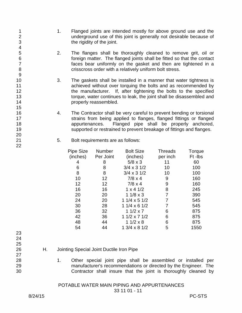
POTABLE WATER MAIN PIPING AND APPURTENANCES 33 11 01 - 11 8/24/15 PC-STS
1. Flanged joints are intended mostly for above ground use and the 1 underground use of this joint is generally not desirable because of 2 the rigidity of the joint. 3
4 2. The flanges shall be thoroughly cleaned to remove grit, oil or 5
foreign matter. The flanged joints shall be fitted so that the contact 6 faces bear uniformly on the gasket and then are tightened in a 7 crisscross order with a relatively uniform bolt stress. 8
9 3. The gaskets shall be installed in a manner that water tightness is 10
achieved without over torquing the bolts and as recommended by 11 the manufacturer. If, after tightening the bolts to the specified 12 torque, water continues to leak, the joint shall be disassembled and 13 properly reassembled. 14
15 4. The Contractor shall be very careful to prevent bending or torsional 16
strains from being applied to flanges, flanged fittings or flanged 17 appurtenances. Flanged pipe shall be properly anchored, 18 supported or restrained to prevent breakage of fittings and flanges. 19
20 5. Bolt requirements are as follows: 21
22 Pipe Size (inches)
Number Per Joint
Bolt Size (inches)
Threads per inch
Torque Ft -lbs
4 8 5/8 x 3 11 60 6 8 3/4 x 3 1/2 10 100 8 8 3/4 x 3 1/2 10 100
10 12 7/8 x 4 9 160 12 12 7/8 x 4 9 160 16 16 1 x 4 1/2 8 245 20 20 1 1/8 x 3 7 390 24 20 1 1/4 x 5 1/2 7 545 30 28 1 1/4 x 6 1/2 7 545 36 32 1 1/2 x 7 6 875 42 36 1 1/2 x 7 1/2 6 875 48 44 1 1/2 x 8 6 875 54 44 1 3/4 x 8 1/2 5 1550
23 24 25
H. Jointing Special Joint Ductile Iron Pipe 26 27
1. Other special joint pipe shall be assembled or installed per 28 manufacturer's recommendations or directed by the Engineer. The 29 Contractor shall insure that the joint is thoroughly cleaned by 30
POTABLE WATER MAIN PIPING AND APPURTENANCES 33 11 01 - 12 8/24/15 PC-STS
removing all dirt, oil, grit, excess coatings and foreign matter to 1 insure a tight joint. 2
3 3.05 REMOVAL OF OUT OF SERVICE PIPE 4 5
A. Due to certain permit requirements, pipe that is to be removed from 6 service will have to be physically taken out of the ground. The limits of 7 pipe to be removed shall be specifically called for in the Plans or shall be 8 approved in writing by the Engineer. Any other removal not specifically 9 called for, shall be considered incidental to construction of other items in 10 the Contract and the Contractor will not receive compensation for such 11 work. 12
13 B. When removing pipe the Contractor shall excavate a trench wide enough 14
to dislodge the pipe from the surrounding soil, and long enough to be able 15 to handle the pipe without causing any damage to nearby utilities, 16 structures or adjacent property. 17
18 C. The removed pipe, fitting and appurtenances will become the Contractor's 19
property and he shall be responsible for proper disposal and any required 20 permits thereof. 21
22 D. Refer to Specification 01 35 00, Special Project Procedures for removal of 23
asbestos cement (AC) pipe. 24 25
3.06 INSTALLATION OF PIPE UNDER DRIVEWAYS 26 27
A. At the Engineer's discretion the Contractor will be required to auger pipes 28 under driveways, structures or trees to avoid removal or expensive 29 restoration of those structures. The Contractor will be allowed to utilize an 30 auger machine and to push or pull the carrier pipe into the bore without 31 the need of a casing. 32
33 B. The Contractor shall install the water pipe within the bore hole on a line 34
and grade to allow connection to open cut piping adjacent to the bore hole 35 within pipe jointing alignment limits defined for the pipe in question. The 36 completed installation shall not result in settlement of soil under the 37 driveway. 38
39 40 41 3.07 INSTALLATION OF PIPE UNDER HIGHWAYS AND RAILROADS 42 43
A. The General Contractor shall furnish and install protective steel pipe 44 casings and/or carrier pipe under highways/railroads in the pipe size, 45 thickness, length, location and details as shown on the drawings and 46
POTABLE WATER MAIN PIPING AND APPURTENANCES 33 11 01 - 13 8/24/15 PC-STS
specified herein. The Contractor's attention is particularly directed to the 1 requirements of the particular municipal or private owner or Department of 2 Public Works having jurisdiction over the highways/railroads whether 3 through permit, verbal or other directions. 4
5 B. The construction shall not be started until the necessary permits have 6
been obtained, a copy is at the job site, and proper notice and approval for 7 construction has been obtained from the owner of the highway/railroad 8 and the Engineer. 9
10 C. All necessary materials, equipment, labor and traffic protection devices 11
shall be on the job site before requesting permission to start the work. 12 13
D. Steel casings and the installation thereof required for highway/railroad 14 crossings shall be in accordance with the standards and requirements of 15 the Florida Department of Transportation (FDOT) or railroads or AASHTO 16 Standards and the Specifications outlined herein. All work of this nature 17 shall be performed by qualified Contractors regularly engaged in that type 18 or work and shall be subject to approval by the Engineer. 19
20 E. All work shall be in accordance with Specification 35 05 20, Jacking and 21
Boring. 22 23
3.08 FITTINGS 24 25
A. All fittings shall be restrained by means of restraining devices such as 26 restainer glands, restraining gaskets, etc. 27
28 B. Fittings shall be set and joined to the pipe and each type of joint as 29
specified for pipe. 30 31 C. Trenching and backfilling for all fittings shall also be in accordance with 32
Section 31 23 33, Excavation and Backfill for Pipes. 33 34
D. The use of thrust blocks in new lines is prohibited and shall be limited to 35 areas in which a new fitting has been installed in an existing line and is not 36 feasible to restrain joints or when directed by the Engineer. 37
38 E. The use of "reverse dead-man" shall be as described under Standard 39
Details for dead-end valves or in circumstances that the Engineer deems it 40 necessary and shall be performed under his direction. 41
3.09 VALVES 42 43
A. Valves shall be set and joined to the pipe and each type of joint as 44 specified for pipe. 45
46
POTABLE WATER MAIN PIPING AND APPURTENANCES 33 11 01 - 14 8/24/15 PC-STS
B. Trenching and backfilling for all valves shall also be in accordance with 1 31 23 33, Excavation and Backfill for Pipes. 2
3 C. Cast iron valve boxes shall be firmly supported, maintained centered and 4
plumb over the operating nut of the valve. Outside of paved areas, valve 5 boxes shall be set in a 2' x 2' x 6" thick concrete collar, along with a brass 6 ID tag, as shown in the Standard Details. The box cover shall be flush 7 with the surface of the finished pavement. All box lids shall be painted 8 OSHA safety blue and shall have the word “WATER” cast in the lid. 9
10 D. All reasonable effort must be made to locate valves/valve boxes behind 11
the back of curb, in grass areas and at street corners, whenever possible. 12 Valves should be kept in clusters within two feet of the tee, when 13 possible. 14
E. Valve boxes in areas that will require sod at a later date must be left 1"-2" 15 above existing grade (to allow for sod thickness). 16
17 F. All valves/boxes shall be located by means of a perpendicular 6" x 2' blue 18
stripe across the curb. The distance from the back of the curb to the valve 19 shall be stenciled on the curb with numbers four inches high, painted blue, 20 by the Contractor. This information will be referenced on the pavement if 21 no curbs are to be installed. The fire hydrant valves shall be stenciled (in 22 the same manner) with the letters H.V. All valve box tops shall be painted 23 blue. All valves must be centered over the operating nut/wheel and all 24 valves after being fully opened, will be backed off one-quarter of a turn to 25 prevent them from being jammed open. 26
27 G. All dead end valves shall be restrained with a reverse deadman, per the 28
Standard Details. 29 30 H. Should the operating nut be more than three feet below the final grade, an 31
extension shall be supplied and installed by the Contractor. The extension 32 shall bring the nut to within twelve inches of final grade. 33
34 I. Installation of Valves on Existing Mains 35 36
1. When installing valves in existing mains (cutting-in) the Contractor 37 shall insure that the pipe is kept clean at all times and no debris, 38 ground water, mud, oil, etc. will make their way into the pipe. 39
2. The Contractor shall notify customers of water service shut-down 40 and shall insure that such is held to a minimum. 41
42 3. The lid shall fit flush in the top of the box without forcing and shall 43
not rock, tip or rattle. Roadway boxes for bypass valves shall be 44 marked "BYPASS". Valve box lids shall be painted blue and 45 referenced to the closest curb by stenciling the distance and by 46

POTABLE WATER MAIN PIPING AND APPURTENANCES 33 11 01 - 15 8/24/15 PC-STS
painting a 6" wide by 2' long stripe perpendicular to the curb of the 1 roadway. 2
3 J. Removal and Disposal of Existing Valves 4
5 1. Any valve, unless otherwise specified, that is removed from the 6
System shall become the property of the Contractor and he shall 7 ensure proper disposal. 8
9 3.10 HYDRANTS 10
11 A. Hydrants shall be placed at a location in which they are completely 12
accessible and the possibility of damage from vehicles is minimal. Unless 13 otherwise directed, the hydrants shall be installed in accordance with the 14 Standard Details.. 15
16 B. All hydrants shall be installed plumb and shall have their pumper nozzle 17
perpendicular to the curb. They shall conform to the established grade 18 with steamer nozzle between eighteen inches (18) to twenty four (24)- 19 inches above the ground. 20
21 C. All hydrants shall be connected to the water main with a six inch branch 22
controlled by an independent 6-inch resilient wedge gate valve that 23 functions as a hydrant shut-off valve. In the event that the hydrant is more 24 than ten (10) feet away from the main line, a second valve shall be 25 installed. 26 27
D. Hydrants shall be restrained as shown in the Standard Details. Thrust 28 blocks shall not be allowed unless specifically approved by the Engineer. 29 All underground pipe and fittings shall be polyethylene encased as 30 described in these Specifications. 31
32 E. All hydrant legs shall be restrained per in accordance with the Standard 33
Details. No threaded rod will be accepted. 34 35
F. All fire hydrant legs greater than ten (10) feet in length shall have two 36 valves, one at the main and one within two feet of the hydrant. 37 38
G. Hydrants in subdivision shall be installed within the space between the 39 sidewalk and the lot line (when said space is available) and on the dividing 40 line between lots or at the PC or PT of the curve along the curb. 41 42
H. In shopping centers and commercial areas, all reasonable effort shall be 43 made to install hydrants in grass areas where there is no traffic. Deviation 44 from this requires prior approval and the installation of protective hydrant 45 guards, per Pinellas County Specifications and the Standard Details. 46

POTABLE WATER MAIN PIPING AND APPURTENANCES 33 11 01 - 16 8/24/15 PC-STS
1 I. Any hydrant located within ten (10) feet of a vehicular use area in an off-2
street location shall be provided with guard posts in accordance with the 3 Standard Details, unless otherwise approved by the Director of Pinellas 4 County Utilities Engineering or his authorized representative. 5 6
J. All fire hydrants shall be flowed during final inspection to ensure proper 7 working condition. 8 9
K. All fire hydrants shall be bagged by the Contractor until put in service 10 following a successful chlorination. 11
12 L. All chains shall be removed from the hydrants, and the hydrants shall be 13
painted in accordance with the Standard Details. 14 15
M. Relocation of Hydrants 16 17
1. When called for on the Plans, the Contractor shall remove and 18 relocate hydrants. The hydrants shall be thoroughly cleaned, bolts 19 and gaskets replaced and a new line valve installed. 20
21 2. The existing shut-off valve shall be plugged and buried. 22
23 N. Removal and Disposal of Hydrants 24
25 1. Any hydrant, unless otherwise specified, that is removed from the 26
System shall become the property of the Contractor and he shall 27 insure proper disposal. 28
29 3.11 FIRE LINES 30
31 A. Fire lines shall have two valves with each valve having a box with lid. One 32
valve shall be located at the water main and the second valve shall be 33 located at the property line. The only deviation shall be at the Engineer's 34 discretion. The property line valve shall have a leak meter wrapped 35 around it. 36
37 B. All private fire lines shall be constructed in accordance with Pinellas 38
County Specifications. This includes pressure testing and chlorination as 39 required. 40
41 C. All fire lines that do not serve a fire sprinkler system shall have a leak 42
detection meter installed around the valve at the property line (installed by 43 the County). 44
45
POTABLE WATER MAIN PIPING AND APPURTENANCES 33 11 01 - 17 8/24/15 PC-STS
D. Fire sprinkler lines shall have a double check valve assembly. A leak 1 detection meter shall be installed on the completed assembly by Pinellas 2 County personnel. Chlorination shall be done as required up to the first 3 O.S. & Y. valve. Additional chlorination may be required behind the 4 device which is under jurisdiction of the Plumbing/Building Code. 5
6 E. If the Siamese connection is on the DCVA or any portion of the line 7
running into the building, Class 50 ductile iron pipe shall be required 8 behind the double check valve assembly to the riser inside the building. 9 DR14 PVC may be substituted up to within five feet of the building, at 10 which point DIP shall then be used as required. Siamese connections 11 shall have an eight inch minimum clearance above finished grade. 12
13 F. All backflow devices on fire lines are to be installed in ten (10) foot wide 14
grass area or protected with a series of modified fire hydrant guards, the 15 quantity and location of such shall be determined by the Engineer or his / 16 her approved or appointed representative. 17
18 3.12 TAPPING OF MAINS 19
20 A. The Contractor, after installing the sleeve and prior to making the tap, 21
shall insure that the sleeve is providing a watertight joint by means of 22 pressure testing with pressures in accordance with 01 45 17, Pipeline 23 Testing Requirements. If leaks are present, the Contractor will be 24 required to repair them to the satisfaction of the Engineer. 25
26 3.13 SERVICE METERS AND ACCESSORIES 27 28
A. Unless specified to be furnished by the Contractor under a separate pay 29 item, all meters, reduced pressure devices, double check valves, etc. will 30 be supplied by the Utilities Department. The Contractor shall pick-up such 31 devices where directed and shall inspect them thoroughly and shall insure 32 that they are in proper working order. 33
34 B. The Contractor shall install meters, backflow devices, double check 35
valves, etc. at locations called for in the Plans, as sketched out or as 36 directed by the Engineer. No meter or accessory is to be installed outside 37 of the right-of-way unless easements have been secured or as specifically 38 directed by the Engineer. 39
C. When relocating meters, the Contractor shall insure that the meter is 40 operational. If the meter or accessories are damaged he shall bring this to 41 the attention of the Engineer. Meter boxes shall be replaced, as well as 42 brass fittings and pipe inserts and shall be considered incidental to the 43 cost of relocating meters. 44
45

POTABLE WATER MAIN PIPING AND APPURTENANCES 33 11 01 - 18 8/24/15 PC-STS
D. All meter, backflow, reduced pressure device, etc. installations shall be 1 made in accordance with Pinellas County Utilities Department Standard 2 Construction Details as shown on these Specifications. 3
4 3.14 SERVICE LINES AND SERVICE CASINGS 5 6
A. Service line casings shall be installed on all long side services. Casings 7 may be installed using the pneumatic bullet method, subject to the 8 requirements of the entity having jurisdiction for the roadway. 9 10
B. Service line casings for one-inch services shall be Schedule 80 PVC or 11 SDR-9 HDPE two inches in diameter for single services, three inches in 12 diameter for double services. 13
14 1. All service lines over (40) forty-feet in length shall have a minimum 15
size of one-inch. 16 17 C. All casings shall be marked on both sides of the road with a six inch wide 18
blue stripe running across the curb in the direction of the casing. A single 19 strand of blue 14 gauge copper wire shall be installed with the casing and 20 extend up the 2 x 4 that is required at the end of the casing. The 2 x 4 will 21 be six feet in length and painted blue. 22
23 D. The depth to the top of the casings shall be thirty (30) inches to thirty-six 24
(36) inches. Casings that are installed deeper than thirty-six (36) inches 25 shall be removed and installed at the correct depth. Casings shall extend 26 a minimum of five feet beyond the existing back-of-curb or edge of 27 roadway. Exceptions to this requirement due to physical constraints shall 28 require prior approval by the Engineer. 29
30 3.15 INSTALLATION OF BOLTS ON MECHANICAL JOINTS 31
32 A. Align bolt holes and insert bolts, with bolt heads behind the bell flange, 33
and tighten opposite nuts to keep the gland square with the socket. 34 35 36 37 38 39 40
Tighten the nuts in accordance with the following table: 41 42
Bolt Diameter (inches)
Torque (ft-lb)
5/8 45-60

POTABLE WATER MAIN PIPING AND APPURTENANCES 33 11 01 - 19 8/24/15 PC-STS
3/4 75-90 1 85-100
1 1/4 105-120 1 3.16 PAINTING 2 3
A. All above ground installations, except for fire hydrants and guard post, 4 shall be painted OSHA safety precaution blue. Paint application shall be 5 in accordance with the paint manufacturer's recommendation. 6
7 B. Paint used on all fire line backflow prevention devices shall be as specified 8
in the County Materials Specification Manual. 9 10
C. Fire hydrants shall be painted yellow with white bonnet per Material 11 Specification Manual. 12
13 D. Guard posts shall be painted OSHA safety yellow. 14 15 E. All painting shall be in accordance with Section 09 91 00, Painting. 16
17 3.17 TESTING AND DISINFECTION 18 19
A. All potable water mains shall be tested and disinfected in accordance with 20 Specifications 01 45 17, Pipeline Pressure and Leakage Testing 21 Requirements and 33 13 01, Disinfection of Potable Water Mains. 22
23 END OF SECTION 24

DISINFECTION OF POTABLE WATER MAINS 7/07/15 33 13 01 - 1 PC-STS
SECTION 33 13 01 1 2
DISINFECTION OF POTABLE WATER MAINS 3 4 5 PART 1 – GENERAL 6 7 1.01 SCOPE OF WORK 8 9
A. This Specification provides written description and direction of required 10 practices to those involved in the process of disinfecting potable water 11 mains and appurtenances prior to their placement for service. 12
13 B. Chlorination shall not take place until: 14
15 1. The main is constructed in accordance with the Contract 16
Documents as modified by the Engineer during construction and all 17 construction permit requirements are met. 18
19 2. All blow offs, injection and sample points are constructed and ready 20
for use. 21 22
3. The main has been pigged and thoroughly flushed with scouring 23 velocities as needed. 24
25 4. The main has been successfully pressure and leakage tested in 26
accordance with Specification 01 45 17, Pipeline Testing 27 Requirements. 28
29 5. Chlorine neutralization chemicals, and methods for application and 30
disposal of chlorinated water, have been established by the 31 Contractor. The Contractor shall dispose of the water without 32 causing a nuisance, property damage and in compliance with the 33 National Pollution Discharge Elimination System (NPDES) and all 34 applicable jurisdictions. 35
36 1.02 APPLICABILITY 37 38
A. All new water mains shall be flushed and disinfected in accordance with 39 ANSI/AWWA C651 and bacteriological samples shall be collected and 40 analyzed on two consecutive days. 41
42 B. Special County Projects (i.e. County Parks, Utility Facilities, etc.) with 43
water lines after back flow prevention and meter assemblies. 44 45
C. New additions or alterations/relocations of water mains less than or equal 46 to 50’ in length shall be disinfected by either the Tablet method, 47

DISINFECTION OF POTABLE WATER MAINS 7/07/15 33 13 01 - 2 PC-STS
Continuous-feed method or swabbing or spraying with a hypochlorite 1 solution and flushed as prescribed in ANSI/AWWA C651. Bacteriological 2 samples shall be collected and analyzed on two consecutive days. 3 4
D. New additions or alterations/relocations of water mains that are over fifty 5 (50) feet in length shall be disinfected and flushed as agreed by the 6 County using the Continuous-feed method as described in ANSI/AWWA 7 C651. Bacteriological samples shall be collected and analyzed on two 8 consecutive days. 9
10 E. All newly disinfected water mains shall maintain, after samples have been 11
collected, a minimum pressure of 20 psi until a Letter of Clearance has 12 been obtained from the (FDEP). 13
14 F. Bacteriological test results for all new and altered public drinking water 15
facilities other than wells will be considered invalid if the results are for 16 samples collected more than sixty (60) days before the results are 17 received by the (FDEP). 18
19 G. Emergency and Special Conditions 20
21 1. In the event of an emergency where time is of the essence and a 22
delay in putting the water main(s) back into service may lead to a 23 detrimental interruption of customer service or adversely affect the 24 integrity of the water distribution system then the following options 25 should be considered. Based upon the circumstances and as 26 directed by the County, disinfection, flushing, and sampling may be 27 completed as using guidance in ANSI/AWWA C651 including Slug 28 method or standard chlorination procedures for disinfection may be 29 implemented. 30
31 1.03 SCHEDULING AND NOTIFICATION 32 33
A. All disinfection of water mains shall be completed by the Contractor under 34 the direct supervision of the Pinellas County Utilities Inspector. The 35 Contractor shall be responsible to provide all the necessary equipment 36 and materials to perform the disinfection in accordance with ANSI/AWWA 37 C651. 38
39 B. Scheduling of the disinfection and flushing of newly constructed or altered 40
water mains require a minimum of 48 business hours notice. The Pinellas 41 County Utilities Inspector shall coordinate disinfection, flushing and 42 bacteriological sampling of newly constructed or altered water mains to be 43 completed within the normal business week and hours. Disinfection and 44 flushing shall be done Monday thru Thursday. 45
46

DISINFECTION OF POTABLE WATER MAINS 7/07/15 33 13 01 - 3 PC-STS
C. The disinfection and sample collection for water lines down stream of a 1 property’s water meter or backflow prevention device is under the jurisdiction 2 of the Plumbing/Building Code. Sample analysis shall be coordinated with 3 State certified labs and results provided to the Building Department having 4 jurisdiction. 5
6 PART 2 – PRODUCTS 7 8 2.01 CHLORINATION CHEMICALS 9 10
A. Forms of chlorine to be used for disinfection shall be as listed in AWWA 11 C651. 12
13 1. Liquid chlorine per ANSI/AWWA B301. 14 2. Sodium hypochlorite liquid per ANSI/AWWA B300. 15
3. Calcium hypochlorite tablets or granules per ANSI/AWWA B300. 16 (Calcium hypochlorite intended for swimming pool disinfection shall 17 not be used.) 18
19 B. All products shall be NSF approved for use with potable water. 20
21 2.02 DECHLORINATION CHEMICALS 22 23
A. Chemicals to be used to dechlorinate flushing water shall be as listed in 24 Appendix C, of AWWA C651. These include: 25
26 1. Sodium Thiosulfate (Na2S2O3*5H2O) 27 2. Sodium Bisulfite (NaHSO3) 28 3. Sodium Sulfite (Na2SO3) 29 4. Sulfur Dioxide (SO2). 30
31 PART 3 - EXECUTION 32 33 3.01 GENERAL 34 35
A. The Contractor shall locate blow-off valves at low points and dead ends in 36 the grid to permit the removal of sediment. 37
38 B. The corporation stop to be used for pressure testing and chlorination shall 39
be installed at the tap valve by the Contractor. 40 41
C. Samples shall be taken only through a PCU approved standpipe 42 assembly. No samples shall be taken through a fire hydrant. Refer to the 43 Standard Details. 44
45
DISINFECTION OF POTABLE WATER MAINS 7/07/15 33 13 01 - 4 PC-STS
D. Disinfection and pressure testing shall be completed on all the new 1 sections of water mains, including the fittings and valves. This shall be 2 determined as being up to the first O.S. & Y, the valve upstream of the 3 back-flow device/water meter or the end(s) of the newly installed water 4 main(s) as applicable. 5
6 E. All blow-off standpipes and injection points shall be removed upon 7
satisfactory completion of sampling and testing. Corporation stop shall 8 remain in the line. Water mains smaller than six inches, or mains without 9 fire hydrants or permanent blowoffs, the temporary blowoff and sample 10 points shall remain installed until such time as the main is cleared and has 11 been flushed before being placed into service. 12
13 F. Teflon tape will be required on all threaded joints to avoid contamination 14
(No pipe dope will be allowed). 15 16
G. It is the Contractor’s responsibility to place blow-off and sample points 17 where designated by the approved plan as agreed upon by the Engineer, 18 County and review & permit authorities. 19
20 H. The County at their discretion shall have the authority to modify this policy 21
according to field conditions in coordination with the Contractor. 22 23
3.02 FLUSHING 24 25
A. All pipelines shall be flushed to remove the lighter solids in the line. 26 Because flushing cannot be relied on to remove heavy material allowed to 27 get into pipeline during installation, every precaution shall be made to 28 protect the pipeline against entrance of foreign material during the 29 installation process. 30
31 B. Every new pipeline shall be flushed at a minimum velocity of 2.5 feet per 32
second (fps) to ensure that the lighter solids are removed from the pipe 33 interior. (Note that it may be difficult to obtain scouring velocities in a pipe 34 over two hundred (200) feet in length.) Discharge velocity can be 35 determined by a simple field procedure involving the "trajectory" method. 36 For any size pipe discharging horizontally three feet above the ground, a 37 stream of water traveling at twelve (12) feet per second will strike the 38 ground six feet away. Similarly, a stream of water traveling at five feet per 39 second will strike the ground more than two feet from the end of the pipe. 40 This test must be made thru an open-ended pipe; it must not end with a 41 valve or fitting, which would be smaller than the inside diameter of the 42 pipe. 43
44 C. All pipelines eight inches in diameter or greater, or pipelines suspected of 45
having heavy foreign material in them, shall be subjected to open end 46
DISINFECTION OF POTABLE WATER MAINS 7/07/15 33 13 01 - 5 PC-STS
flushing to remove any foreign material from the pipeline. Pigging is 1 required in addition to open-end flushing. 2
3 D. A velocity of 5.0 fps is desirable and a velocity of 12 fps may be needed to 4
remove sand from river undercrossings and other subsurface inverts. 5 6 E. Table 1, provided at the end of this Specification, outlines the number and 7
size of flushing assemblies required. 8 9 F. During the flushing process, a clean white cup shall be used at all 10
sampling points to visually check for water clarity. When all the sample 11 points are clear, meaning there is no background sediment, and the 12 system chloramines residual is present, the line is ready to schedule for 13 chlorination. 14
15 G. In the case of mains twenty-four (24) inch and larger, preliminary flushing 16
may be replaced by stringent measures for removal of dirt and sediment 17 from the pipe and the thorough cleaning of its interior prior to filling with 18 the high chlorine solution. Swabbing with a chlorine solution may be 19 required at the discretion of the Engineer. 20
21 3.03 CHLORINATION 22 23
A. Upon satisfactory completion of all testing and flushing, the Contractor 24 shall furnish all materials and labor necessary to disinfect all water mains 25 in accordance with the applicable sections of AWWA C-601. 26
27 B. Prior to chlorine injection the following shall be ensured: 28 29
1. That the source water tap valve for the water mains to be 30 chlorinated has been shut off. 31
32 2. That all blow offs and sample points involved in the Project are 33
open. 34 35 3. That there are no open valves to activate water mains tied into the 36
water mains to be chlorinated. 37 38 4. That there is a uninterrupted supply of potable water or adequate 39
number of barrels to assure there is no interruption once the 40 injection process begins. 41
42 C. Disinfection of water mains shall be completed in accordance with 43
ANSI/AWWA C651 standards and shall include the following; preflushing 44 or cleaning of the water mains before the application of chlorine, 45 disinfecting the mains with the prescribed chlorine dose for the disinfection 46
DISINFECTION OF POTABLE WATER MAINS 7/07/15 33 13 01 - 6 PC-STS
method being utilized, allow for the proper amount of chlorine holding or 1 contact time, ensuring that the applicable chlorine residual was maintained 2 for the duration of the disinfection period, and final flushing and clearing of 3 the heavily chlorinated water with the disposal and treatment of the heavily 4 chlorinated water in accordance with applicable dechlorination methods. 5 All sampling points shall be at sites as designated by the approved plan or 6 (500) feet intervals or as agreed upon by the County as conditions dictate. 7 Satisfactory bacteriological analysis shall be determined by the results of 8 samples collected by the County Water Quality Management and 9 analyzed by the Pinellas County state certified lab in accordance with 10 Pinellas County Operating Procedures. 11
12 D. The County shall furnish the Contractor with sufficient water to perform the 13
disinfection required. As the chlorine solution is being injected the 14 chlorine residual at the closest sample point to the injection point shall be 15 tested with a high Cl2 test kit or OTO reagent as applicable. Pinellas 16 County Utilities has set 50 mg/l as the targeted free chlorine residual for 17 new water main clearances as measured at the end of pipeline discharge. 18 The water flow or solution strength shall be adjusted as necessary to 19 achieve the recommended minimum chlorine strength. 20
21 E. As the high chlorine solution reaches each successive sample point, the 22
valve at the sample point shall be closed. Prior to closing the valve at the 23 last sample point, the following water main shut down process shall take 24 place in sequence: 25 1. The source water control valve shall be closed. 26 2. The injection pump should be shut off and its valve closed. 27 3. The last blow off/ sample point valve should be closed. 28
29 ALL BLOW-OFF VALVES SHALL NEVER BE CLOSED BEFORE THE 30 SOURCE WATER VALVE IS CLOSED. 31
32 F. The initial chlorine solution shall be no less than 50 ppm and not more 33
than 1000 ppm in concentration and shall be left standing in the main for a 34 period of not less than twenty-four (24) hours and not more than forty-35 eight (48) hours. There must be a chlorine residual of 10 ppm at the 36 standpipe hose bib after twenty-four (24) hours. After this period, the high 37 chlorine water shall be drained and/or flushed from the system. 38
39 3.04 DRAINING, FLUSHING AND NEUTRALIZATION 40
41 A. Draining and/or flushing the solution from the main shall be the 42
responsibility of the Contractor and shall be performed so as not to cause 43 damage to the environment or create a nuisance to the owners of adjacent 44 property. The Contractor shall inform the Engineer of the proposed 45
DISINFECTION OF POTABLE WATER MAINS 7/07/15 33 13 01 - 7 PC-STS
methods of disposal of the high chlorine solution and shall secure any 1 permits that may be necessary to dispose of such material. 2
3 B. Where applicable flushed water shall be treated to remove the chlorine 4
residual from the water being discharged that has the potential to impact 5 storm sewer, retention pond, lake, bay, gulf, or any other body of water, 6 chemicals for dechlorinating the water shall be as specified above. See 7 AWWA Standard C651, Disposal of Heavily Chlorinated Water, Appendix 8 C for additional details. This process shall be followed each time water is 9 discharged. 10
11 3.05 SAMPLING 12 13
A. The Contractor shall schedule bacteriological sampling through the 14 Pinellas County Inspector. A representative from the County Water 15 Quality Management shall meet with the Pinellas County Inspector and/or 16 the Contractor as applicable. 17
18 B. Before the water samples are collected, the Contractor shall ensure that 19
all the blow off(s) and sample point(s) are opened and that the source 20 water control valve is open. 21
22 C. Bacteriological sampling shall be conducted in accordance with Florida 23
Administrative Code (F.A.C.) 62-555.340. Samples may be collected after 24 first reducing the disinfection residual to no more than 4 mg/L or the 25 representative disinfection residual of the source water. Disinfection 26 residuals shall be measured and recorded. Bacteriological samples shall 27 be collected and analyzed on two or more consecutive business days 28 each taken at least six (6) hours apart. Samples shall be analyzed for the 29 presence of total coliform by the Pinellas County state certified lab. 30
31 D. Prior to initiating sampling, the WQM specialist will check for the Total 32
Chlorine Residual at the last sample point and confirm that the residual is 33 representative of the incoming source water. 34
35 E. If the Total Chlorine Residuals are satisfactory, the specialist will begin 36
water sample collection. 37 38 F. After the sampling is completed, the Contractor shall initiate the shut down 39
process using the following sequence: 40 41
1. Turn off blow off(s) and sample point(s). 42 2. Shut off the control valve. 43
44 G. Main Clearance Sampling is completed when each sample site has two 45
consecutive day satisfactory (Total Coliform Absent) results. 46

DISINFECTION OF POTABLE WATER MAINS 7/07/15 33 13 01 - 8 PC-STS
1 H. Bacteriological test results for new and altered public drinking water mains 2
will be considered invalid if the pressure in the mains is not maintained at 3 20 psi or greater after the samples are collected. 4
5 I. Flushing and sampling shall be repeated, as required, if total coliform is 6
detected in a water sample. If necessary, the main shall be re-chlorinated. 7 8 9 3.06 ACTIVATION OF NEW WATER MAINS 10 11
A. No section of any main shall be put into service without the written 12 permission of the County and after the (FDEP) has cleared such main for 13 use. 14
15 B. After the Final or Partial “Letter of Clearance” has been issued by the 16
(FDEP) for a newly constructed water main and Pinellas County Utilities 17 Engineering is ready to authorize its activation, the water main(s) needs to 18 be thoroughly flushed before it is actually placed into service. 19
20 C. To achieve this flushing, fire hydrants may be utilized on 6-inch and larger 21
water mains. On water mains less than 6-inches, a permanent blow-off 22 may be used if provided. Otherwise the temporary blow-offs setup for the 23 flushing, chlorination and main clearance sampling procedures must be 24 utilized. 25
26 D. Before activation, new water mains should be flushed until the water runs 27
clean and clear. In addition, after the water main has been flushed, field 28 tests for Total Chlorine should be taken to ensure disinfection residuals 29 are similar to and representative of the source water. If the flushing has 30 been thoroughly completed, and a Total Chlorine residual greater than 1.5 31 to 1.8 is not detected, Pinellas County Utilities Water Quality Management 32 should be notified for additional follow up. 33
34 E. If a water main tie-in is involved or if the pressure in the main was not 35
maintained at 20 psi or greater, Pinellas County Utilities Water Quality 36 Management should be notified and water samples for bacteriological 37 analysis should be collected. 38
39 40 41 42 43
44 45
TABLE 1 46 47

DISINFECTION OF POTABLE WATER MAINS 7/07/15 33 13 01 - 9 PC-STS
REQUIRED OPENINGS TO FLUSH PIPELINES (40 PSI RESIDUAL PRESSURE) 1 (For information purposes only) 2
3
4 5 Note: A 2 1/2-inch hydrant outlet nozzle will discharge approximately 1,000 gpm and a 6 4 1/2–inch hydrant outlet nozzle will discharge approximately 2,500 gpm with 40 psi 7 residual pressure. 8
9 10
END OF SECTION 11
Pipe Size Flow (gpm
Required to Produce 2.5 fps
Velocity
Orifice Size (in.)
Number of Hydrant
Outlet Nozzles
Size (in.) of Hydrant Outlet
Nozzles
2 25 2 1 2-1/2 4 100 2 1 2-1/2 6 220 2 1 2-1/2 8 390 2 1 2-1/2
10 610 2-5/16 1 2-1/2 12 880 2-13/16 1 2-1/2 14 1200 3-1/4 2 2-1/2 16 1565 3-5/8 2 2-1/2 18 1980 4-3/16 2 2-1/2

SUBMERSIBLE WASTEWATER PUMPING STATIONS 8/24/15 33 32 00 - 1 PC-STS
SECTION 33 32 00 1 2
SUBMERSIBLE WASTEWATER PUMPING STATIONS 3 4 5 PART 1 – GENERAL 6 7 8 1.01 SCOPE OF WORK 9
10 A. The Contractor shall furnish all labor, materials and equipment to 11
construct and install a complete, automatic, underground pumping station 12 with all factory-built equipment installed in a reinforced concrete pump wet 13 well and shall furnish and install a reinforced concrete valve chamber 14 complete with all pipe, valves, and fittings. 15
16 B. The Contractor shall furnish all labor, materials and equipment to setup, 17
maintain and operate a sewage bypass system as necessary during the 18 proposed construction. It is required that the bypass system include a 19 backup pump to prevent spills during a primary bypass pump failure. The 20 contractor shall be responsible for any wastewater spills during the bypass 21 operation and pay any and all fines, fees, property damage, environmental 22 damage and cleanup costs that are associated with wastewater spills. 23 The Contractor is responsible for providing by-pass pumps which shall not 24 create a nuisance. The contractor will be required to use electric by-pass 25 pumps when not in compliance with the local code noise requirement. 26
27 C. Principal items of equipment included in the pump station: one set of 28
pumps, one spare pump (unless noted otherwise by Pinellas County 29 Utilities), valves, piping, automatic pump level sensor controller, GreyLine 30 or Engineer of Record approved equal sonic-type of level sensor 31 controller) will be the primary choice for pump level sensor controller (with 32 Digital Controls bubbler system as a secondary choice), level sensor float 33 backup system (Flygt or Engineer of Record approved equal), central 34 control panel with circuit breakers and motor starters, all wiring and 35 wetwell level sensors connected to SCADA system and mounted in the 36 SCADA panel. 37
38 D. Each pump station site shall have Metal Halide area lighting. Lighting to 39
be controlled by a switch located as designated by the Engineer and 40 Pinellas County. All area lighting shall be installed a minimum of ten (10) 41 feet above ground on a concrete pole as designated by Pinellas County. 42 Area aesthetics will be the primary consideration for area lighting detail. 43
44 E. Each pump station site shall be provided with an appropriate driveway 45
(Concrete, asphalt or millings), appropriate vinyl fencing and site 46 landscaping as requested by Pinellas County. 47
SUBMERSIBLE WASTEWATER PUMPING STATIONS 8/24/15 33 32 00 - 2 PC-STS
1 F. Each pump station shall be evaluated to determine if an odor control 2
system is required. 3 4 G. Each pump station shall have a potable “safety and sanitation” water 5
supply connection for wet well cleaning. A potable water connection, 6 installed with appropriate back flow prevention device, shall be provided. 7 Where potable water is unavailable, a reclaimed water connection shall be 8 provided, if available. 9
10 1.02 WARRANTY 11
12 A. The Contractor shall guarantee the entire installation, labor and materials 13
for eighteen (18) months. The Contractor shall repair or furnish without 14 charge similar part or parts, which within eighteen (18) months after date 15 of acceptance, prove to be defective. 16
17 PART 2 –PRODUCTS 18 19 2.01 STRUCTURES 20 21
A. Reinforced concrete pipe installed vertically for use as a pumping station, 22 shall have steel reinforcement equal to or exceeding ASTM designation 23 C478, latest revision, and shall conform or exceed the wall thickness of 24 Table 2, Wall B, ASTM designation C-76, latest revision. Concrete shall 25 be 4000 psi/28 day and shall be made using Type II Portland Cement. 26 Valve vaults may be precast or poured in place concrete. Top slabs to be 27 per the plan drawings for both structures. 28
29 B. Concrete ingredients shall conform to as follows: 30
31 1. Portland Cement: Type II per ASTM Specifications C-150 32 2. Aggregate: 1” to #4 per ASTM Specification C-33 33 3. Sand: 2.35 fineness modulus, free from organic matter 34 4. Water: Clean and suitable for domestic use 35 5. Air: Maximum 5 percent entrained 36
37 C. Ballast concrete shall be 2500 psi/28 day and emplaced as shown on 38
plans. 39 40
D. Slab shall be 3500 psi/28 day concrete and shall be placed on two layers 41 of waterproof membrane. 42
43 E. Fiberglass Liners shall be as specified in the Materials Specification 44
Manual and shall be specifically manufactured for sewer use. These 45 products shall meet all requirements of latest ASTM designation C-582 46 (plastic laminates) and ASTM designation C-581 (chemical resistance). 47

SUBMERSIBLE WASTEWATER PUMPING STATIONS 8/24/15 33 32 00 - 3 PC-STS
The properly installed liners shall not fail under H-20 dynamic wheel load 1 applied vertically. Liner shall be installed in accordance with 2 manufacturer’s requirements. The liner shall be tested in accordance with 3 ASTM-3753. 4
5 F. All exposed interior wet well top surfaces shall be covered with 1/8-inch 6
minimum thickness continuous fiberglass sheet adequately anchored to 7 the concrete. 8
9 2.02 EQUIPMENT 10 11
A. Pumps 12 13
1. The pumps shall be capable of handling raw, unscreened sewage. 14 The design shall be such that the pumps will be automatically 15 connected to the discharge piping when lowered into place. The 16 pumps shall be easily removable for inspection or service, requiring 17 no bolts, nuts or other fastenings to be removed for this purpose. 18
19 2. Each pump shall be fitted with a lifting lug, bracket, etc. of adequate 20
strength and length to permit raising the pump for inspection and 21 removal. 22
23 3. The starter casing, oil/air casing and impeller shall be of grey iron 24
construction, with all parts coming into contact with sewage, 25 protected by a coat of rubber-asphalt paint. All external bolts and 26 nuts shall be of 304 stainless steel. The impeller shall be protected 27 by a rotating stainless steel or bronze wear ring and stationary 28 neoprene “O” ring at the inlet of the pump. The impeller shall be of 29 a single vane, nonclog design, capable of passing solids, fibrous 30 material, and heavy sludge, and constructed with long throughway 31 with no acute turns. 32
33 4. Each pump shall be provided with a tandem double mechanical 34
seal running in an oil reservoir, composed of two separate lapped 35 face seals, each consisting of one stationary and one rotating 36 tungsten-carbide ring with each pair held in contact by a separate 37 spring, so that the outside pressure assists spring compression in 38 preventing the seal faces from opening. The compression spring 39 shall be protected against exposure to the pumped liquid. The 40 pumped liquid shall be sealed from the oil reservoir by one face 41 seal and the oil reservoir from the motor chamber by the other, as 42 required. The seals shall require neither maintenance nor 43 adjustment, and shall be easily replaced. 44
45 5. A sliding guide bracket shall be an integral part of the pumping unit 46
and the pump casing shall have a machined angle connection with 47

SUBMERSIBLE WASTEWATER PUMPING STATIONS 8/24/15 33 32 00 - 4 PC-STS
yoke to connect with the cast iron discharge connection, which shall 1 be bolted to the floor of the sump and so designed as to receive the 2 pump angle connection without the need of any bolts or nuts. The 3 anchoring of the pump to the wet well floor shall include any pad or 4 pedestal to allow unimpeded flow to the impeller per the 5 recommendation and detail of the pump manufacturer. 6
7 6. Sealing of the pumping unit to the discharge connection shall be 8
accomplished by a simple linear downward motion of the pump with 9 the entire weight of the pumping unit guided to and wedging tightly 10 against the angled discharge connection; no portion of the pump 11 shall bear directly on the floor of the sump and no rotary motion of 12 the pump shall be required for sealing. 13
14 7. The pump motor shall be housed in watertight casing and shall 15
have Class F insulated windings which shall be moisture resistant. 16 Pump motors shall have cooling characteristics suitable to permit 17 continuous operation in a totally, partially or non-submerged 18 condition. The pump shall be capable of running dry in a totally dry 19 condition for extended periods under full load without damage. 20
21 B. Sewage Pumps and Motors 22
23 1. All sewage pumps shall be Flygt N-Series, or Engineer of Record 24
approved equal, with 230/460 volt, 3 phase, 60 cycle motors. 25 Impellers shall be capable of passing a three inch sphere and 26 delivering the GPM and TDH as shown on the plans. 27
28 C. Access Frame and Guide Bars 29
30 1. An aluminum access frame complete with checkered aluminum 31
doors rated at three hundred (300) pounds per square foot, as 32 manufactured by Bilco or Halliday, shall be furnished unless 33 conditions, i.e. vehicle loading, etc, require a higher load rating 34 door. Stainless steel door hinges will be recessed and vandal-35 proof; hasp will be fabricated of round bar stock mounted vertically 36 and drilled to accept a padlock. A fall prevention system shall be 37 incorporated into the access frame. 38
39 2. Doors over fifty (50) pounds in pull-weight shall be torsion bar 40
loaded, all will have a locking safety handle to hold them in the 41 open position. Valve pit and wet well doors, in the open position, 42 shall provide a clear opening to allow for service and removal of 43 equipment (including pumps with mix flush valves). The upper 44 guide and cable holder shall be furnished and securely mounted to 45 the opening using 3/8” x 2 1/4” long stainless steel wedge anchors. 46 Two stainless steel pump guide bars (SAE 304, schedule 40) of a 47
SUBMERSIBLE WASTEWATER PUMPING STATIONS 8/24/15 33 32 00 - 5 PC-STS
size shown on the drawings, shall be furnished for each pump and 1 shall be of adequate length to extend from the lower guide holders 2 on the pump discharge connection to the upper guide holder 3 mounted on the access frame using 3/8” X 2 1/4" long stainless 4 steel wedge anchors. Intermediate guide bar brackets shall be 5 installed where depth of station is greater than eighteen (18) feet. 6
7 D. Valves and Piping 8
9 1. Gate valves, four inch through sixteen (16) inch diameter, shall be 10
AWWA standard for resilient seated gate valves, NRS open left and 11 rated at 250 psi minimum. Valves in vaults shall have flanged 12 connections with a hand wheel operator. Buried valves shall have 13 mechanical joint connections with a two-inch operating nut, 14 supplied with a valve box, bronze identification disk and concrete 15 valve box collar as shown in the Standard Details. 16
17 2. Piping shall be flanged ductile iron (no flange adapters will be 18
accepted). Duplex pump discharge lines shall be flanged ductile 19 iron (no flange adapters will be accepted) jointed by a double 20 branch ninety (90) degree ductile iron elbow to the common outlet. 21 Triplex pump discharge lines shall be flanged ductile iron (no flange 22 adapters will be accepted) jointed by a ductile iron cross to the 23 common outlet. A flanged wall pipe shall connect the riser pipe. 24 MJ wall sleeves shall be utilized to make the horizontal connection 25 to the riser. Pipe sizing shall be in accordance to plans. A line 26 valve shall be installed within five feet of the valve pit with an 27 external bypass system. 28
29 3. Discharge piping shall have two 1/2-inch stainless steel ball valves 30
installed to permit pump performance testing. The ball valves shall 31 be installed upstream of the pump discharge check valves 32
33 4. A by-pass draw tube shall be installed on stations that have two 34
hour retention time or less, and six inch draw tubes.. Bypass valves 35 should be 6” or greater when head condition exceeds 40’. 36
37 5. All hardware (bolts/nuts) on flange by flange piping shall be 304 38
stainless steel. 39 40 E. Pump Station Control Panel Specifications 41
42 1. The control panel enclosure shall be stainless steel, NEMA 4X 43
(sized per the Appendix Schedule 1). There shall be polished 44 aluminum dead front inner door. The dead front shall be mounted 45 on a stainless steel continuous hinge (piano) mounted with pop 46 rivets, with a positive mechanical quarter-turn handle catch and 47 shall open at least ninety (90) degrees F. A method of holding the 48

SUBMERSIBLE WASTEWATER PUMPING STATIONS 8/24/15 33 32 00 - 6 PC-STS
dead front door in the open position shall be provided. A method of 1 securing a standard padlock, thereby locking the cabinet outer 2 door, shall be provided. All panels shall be equipped with stainless 3 steel wire terminals. 4
5 2. The dead front door shall contain the following labeling: Access to 6
circuit breakers, HAND-OFF-AUTO-RTU pump selector switches 7 with green light for auto, yellow level indicator pilot lights, red pump 8 run pilot lights, red alarm pilot light, maintenance switch with yellow 9 pilot light, phase monitor test switch, green watchdog activated pilot 10 light, and a 20 amp GFI receptacle. All indicator lights shall be 11 lamp trade number (1819). 12
13 3. A MELTRIC #37-27-043 generator receptacle shall be mounted on 14
the side of the control cabinet in the down position. Main circuit 15 breaker and Emergency generator circuit breaker shall be inter-16 locked to prevent back feed. All circuit breakers shall be Square D 17 FAL series or larger as required, and sized for the available power 18 company fault current. Where a “high” leg service exists, it shall be 19 connected to the “B” phase of the main breaker. Most applications 20 will be duplex pumps unless otherwise specified. 21
22 4. The motor starter sub panel shall contain Square D Model #8536 23
(Type P starters are not acceptable) across-the-line NEMA-rated 24 magnetic starters with individual over-load on each leg and one 25 hundred 120 volt coil control. Across the line motor starters with 26 thermal overload protection shall be used when pump horsepower 27 is less than 20 hp on a 240 volt or less voltage feed or 20 28 horsepower on 480 volt or less voltage feed. Additionally, a VFD 29 shall be installed for all applications. All control wiring shall be 30 surface mounted, void of splices, have appropriate color coded or 31 numbered terminal ends, sized 14 minimum, type THHN or 32 equivalent, rated for six hundred (600) volts, stranded tinned 33 copper conductor colors are as follows: 34 35 a. 120V-A/C 36 Blue-Hot 37 White – Neutral 38 39 b. 24V-A/C 40 Orange – Hot 41 Grey – Neutral 42 43 c. 12V D/C 44
Red – Positive 45 Black – Negative 46
47
SUBMERSIBLE WASTEWATER PUMPING STATIONS 8/24/15 33 32 00 - 7 PC-STS
d. Green – Ground 1 2
3 4 5
e. Diversified Electronics - Pump Alternator Only 6 Brown – 1 Input 7 Yellow – Common Input 8
9 f. RTU colors are per Pinellas County Utilities standard. 10 11
5. Control relays shall be 8 pin plug-in type and a LED pilot light to 12 indicate when energized. Relay sockets shall be surface mounted. 13 120V to 24 volt step down transformers shall be minimum, .075KVA 14 rated and primary and secondary fused. Alternators shall be 15 Diversified Electronics solid state 8 pin plug-in type with indicator 16 LED’s, a switch to select automatic or lead pump operation, and a 17 test switch. A battery alarm system (STA-CON B.O.A.C.) shall be 18 provided in the panel. A red-flashing light and an audible alarm 19 (wheel-lock model #EH-EL2) compatible with the Sta-con alarm 20 system. Alarm horn and light shall be mounted on site for optimum 21 placement. An outside horn cancel button, that shall work on 22 power failure, shall be installed. 23
24 6. All three-phase panels shall have an electronic solid state phase 25
monitor and use pin wiring configuration compatible with current 26 stations as follows: 240 volt systems shall use the Diversified 27 Electronics 8 pin plug-in type; 480 volt systems shall use hard-28 wired surface mounted unit. The loss of any phase shall actuate 29 the battery alarm and open the 120 volt neutral. This phase loss 30 shall disconnect the 120 volt neutral from the 120 volt control 31 section. 32
33 7. Control circuitry shall be designed as per Pinellas County Utilities 34
standards. A solid state lightning surge protector with a clamping 35 time of ten (10) nanoseconds shall be Innovative Technologies 36 XT40 (230v.,1ph), XT40 (230v, 3ph) or XT40 (480v, 3ph) or EQX80 37 and be weatherproof for external mounting. The surge protector 38 shall be mounted on the outside of the disconnect control panel on 39 the load side. A NEMA 4 stainless steel, fusible, horsepower rated 40 disconnect switch shall be provided and drilled for padlock security 41 in the “OFF” position. The disconnect shall isolate the non-fusable 42 utility power from the control panel. A second similar disconnect is 43 required before the meter in 480 volt applications by the power 44 company. An 11” x 17” schematic and pump data sheet shall be 45 permanently affixed to the interior of the enclosed door. Lamination 46 shall be provided to protect the data sheet. A stainless steel NEMA 47 4x junction box (minimum 14” x 12” x 6” and a minimum 24” x 24” x 48

SUBMERSIBLE WASTEWATER PUMPING STATIONS 8/24/15 33 32 00 - 8 PC-STS
8” for 20 H.P. and larger) with bottom or side hinged cover shall be 1 installed between the control panel and the wet well. It shall house 2 the terminal strip, which shall be stainless steel, mounted on an 3 aluminum din rail, for pump, float, RTU and sensor connections 4 (24). There shall be twelve (12) inches minimum clearance 5 between the bottom of the junction box and slab top elevation. 6
8. The control panel and the junction box shall be connected by 7 means of a 1-1/2-inch (minimum size) conduit with appropriately 8 sized in-line gas seal-off. Myers Hub or other similar, reusable, 9 water-proof fitting shall be installed where any conduit enters the 10 top or side of any box. The junction box shall have one 2-inch PVC 11 (minimum size) conduit for each pump, and two 2-inch PVC 12 (minimum size) conduits for the floats. All conduits between the 13 junction box and the wet well shall be sealed with duct seal or 14 approved equal. Re-usable butterfly clamps shall be used in the 15 junction box to secure motor, float and level controller leads. The 16 control panel and disconnect switch shall be mounted plumb on two 17 6” x 6” x 10’ (minimum) pre-cast concrete posts buried three feet in 18 the ground. The overall length of the post shall be determined by 19 the size of the panel and the three feet minimum distance required 20 between the bottom of the panel and slab top elevation. All 21 mounting hardware shall be 304 stainless steel. If UNI-STRUT is 22 used, it shall be of 304 stainless steel. Larger than 20 H.P. 23 applications shall have conduit for pump cable sized so that the 24 cable does not occupy more than twenty-five (25) percent of the 25 conduit. 26
27 9. All stand alone (pedestal mounted) panels shall have 304 stainless 28
steel Uni-strut welded to the rear of the panel to support meter can, 29 fusible disconnect and junction box. In addition the pedestal 30 mounted panel shall be securely anchored to a six inch thick, 31 reinforced with #4 bars at eight inches o.c. both ways, 3500 psi 32 concrete slab. 33
34 10. All grounding grids (delta) shall consist of a minimum of three each 35
5/8-inch, copper-clad steel sectional ground rods, which are 36 compression-coupled. The depth of all ground rods will be 37 determined by a using IEEE "Fall of Potential Method" and shall be 38 so noted on a Certified Ground Test Document, which shall be 39 provided by the installer. Ground resistance shall test at or below 40 10 OHMS, un-bonded. All conductors shall consist of copper rope-41 lay cable composed of a minimum of twenty-eight (28) strands of 42 14 gauge wire weighing not less than 375 pounds per 1,000 feet. 43
44 11. All ground grid system connections shall be made using the 45
exothermic process, CADWELD, or other approved equal 46 manufacturer. All underground connections shall be via exothermic 47

SUBMERSIBLE WASTEWATER PUMPING STATIONS 8/24/15 33 32 00 - 9 PC-STS
welding. All structures shall be bonded to the closest electric 1 service ground via the main size conductor and/or a water service 2 pipe. The bonding shall be accomplished to achieve equal 3 potential of all grounds. Delta grids shall be tested without the 4 service and water main connection, and documented as such, and 5 then connection to service and water main can be made. The 6 ground resistance of the completed system shall be measured, and 7 listed on the Certified Ground Test Document. 8
9 12. All conductors, other than those supplied from the power company, 10
shall be 600 volt rated stranded copper THHN insulation or 11 equivalent and be run in PVC conduit or as per code requirements. 12 The service conductors shall have ampacity ratings that meet or 13 exceed the main breaker ampacity. All utility services, not supplied 14 by the power company, shall be supplied by the contractor and 15 shall be underground in conduit. 16
17 13. The Contractor shall be responsible to verify power company 18
requirements prior to ordering equipment and beginning any work. 19 All workmanship shall be done in a professional manner and will 20 meet all NEC and NEMA codes. The enclosure and components 21 shall be UL approved. 22
23 14. Twenty four (24) din rail mounted RTU terminals shall be supplied 24
and mounted vertically as close to bottom center of cabinet as 25 possible. Above the terminals shall be seven RTU relays mounted 26 and wired as per the supplied prints. 27
28 15. SCADA and RTU requirements shall be as specified in Section 29
40 95 01, Wastewater Pump Station SCADA Remote Telemetry 30 Unit (RTU). 31
32 F. Mixing/Flushing 33
34 1. All pump stations shall have a mixing and/or flushing capability so 35
that at minimum the fluid in the wet well is mixed once per 36 alternation cycle (i.e. one mixer/flusher per duplex setup, two per 37 triplex setup). Location of mixing and/or flushing valve shall be 38 determined in the field by the Engineer and Pinellas County 39 Engineering. 40
41 G. Wiring 42
43 1. The pump station shall be factory wired for the electric service to 44
the central control panel and either a 100 amp or 200 amp (sized 45 as required) fusible disconnect switch in a stainless steel rain tight 46 enclosure to be located between the electric meter and the control 47 panel of all 230 volt electrical services and a stainless steel rain 48 tight enclosure to be located on each side of the electric meter of all 49
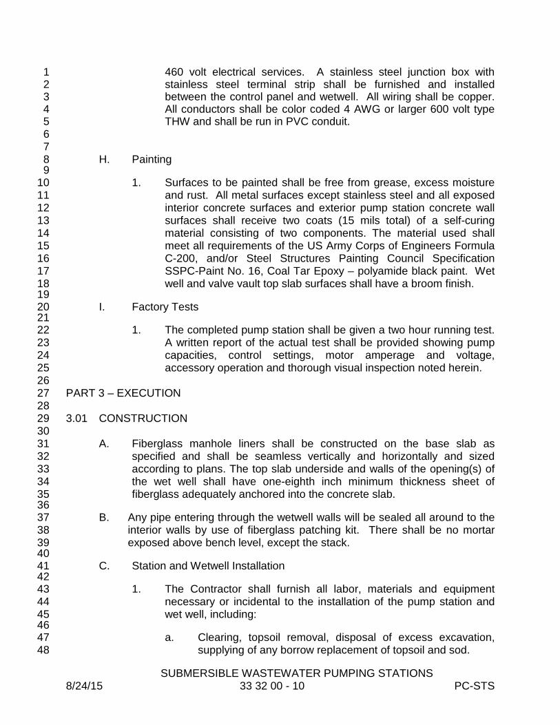
SUBMERSIBLE WASTEWATER PUMPING STATIONS 8/24/15 33 32 00 - 10 PC-STS
460 volt electrical services. A stainless steel junction box with 1 stainless steel terminal strip shall be furnished and installed 2 between the control panel and wetwell. All wiring shall be copper. 3 All conductors shall be color coded 4 AWG or larger 600 volt type 4 THW and shall be run in PVC conduit. 5
6 7 H. Painting 8
9 1. Surfaces to be painted shall be free from grease, excess moisture 10
and rust. All metal surfaces except stainless steel and all exposed 11 interior concrete surfaces and exterior pump station concrete wall 12 surfaces shall receive two coats (15 mils total) of a self-curing 13 material consisting of two components. The material used shall 14 meet all requirements of the US Army Corps of Engineers Formula 15 C-200, and/or Steel Structures Painting Council Specification 16 SSPC-Paint No. 16, Coal Tar Epoxy – polyamide black paint. Wet 17 well and valve vault top slab surfaces shall have a broom finish. 18
19 I. Factory Tests 20
21 1. The completed pump station shall be given a two hour running test. 22
A written report of the actual test shall be provided showing pump 23 capacities, control settings, motor amperage and voltage, 24 accessory operation and thorough visual inspection noted herein. 25
26 PART 3 – EXECUTION 27 28 3.01 CONSTRUCTION 29
30 A. Fiberglass manhole liners shall be constructed on the base slab as 31
specified and shall be seamless vertically and horizontally and sized 32 according to plans. The top slab underside and walls of the opening(s) of 33 the wet well shall have one-eighth inch minimum thickness sheet of 34 fiberglass adequately anchored into the concrete slab. 35
36 B. Any pipe entering through the wetwell walls will be sealed all around to the 37
interior walls by use of fiberglass patching kit. There shall be no mortar 38 exposed above bench level, except the stack. 39
40 C. Station and Wetwell Installation 41
42 1. The Contractor shall furnish all labor, materials and equipment 43
necessary or incidental to the installation of the pump station and 44 wet well, including: 45
46 a. Clearing, topsoil removal, disposal of excess excavation, 47
supplying of any borrow replacement of topsoil and sod. 48
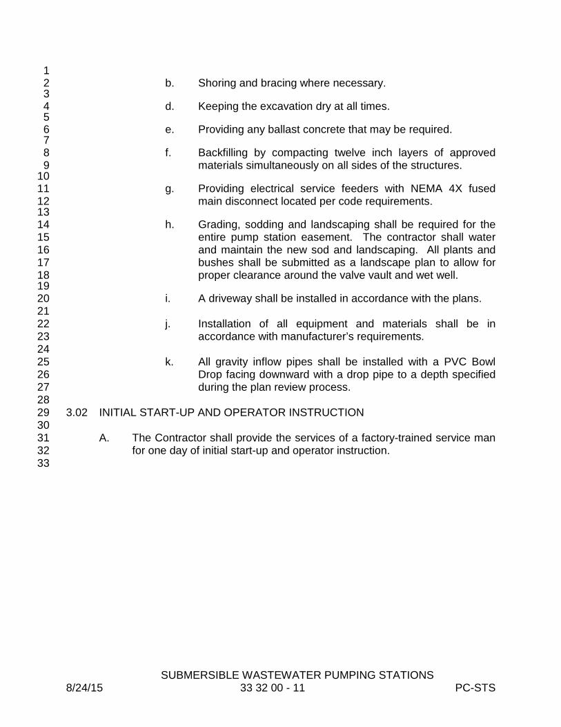
SUBMERSIBLE WASTEWATER PUMPING STATIONS 8/24/15 33 32 00 - 11 PC-STS
1 b. Shoring and bracing where necessary. 2 3 d. Keeping the excavation dry at all times. 4 5 e. Providing any ballast concrete that may be required. 6 7 f. Backfilling by compacting twelve inch layers of approved 8
materials simultaneously on all sides of the structures. 9 10 g. Providing electrical service feeders with NEMA 4X fused 11
main disconnect located per code requirements. 12 13 h. Grading, sodding and landscaping shall be required for the 14
entire pump station easement. The contractor shall water 15 and maintain the new sod and landscaping. All plants and 16 bushes shall be submitted as a landscape plan to allow for 17 proper clearance around the valve vault and wet well. 18
19 i. A driveway shall be installed in accordance with the plans. 20 21 j. Installation of all equipment and materials shall be in 22
accordance with manufacturer’s requirements. 23 24 k. All gravity inflow pipes shall be installed with a PVC Bowl 25
Drop facing downward with a drop pipe to a depth specified 26 during the plan review process. 27
28 3.02 INITIAL START-UP AND OPERATOR INSTRUCTION 29 30
A. The Contractor shall provide the services of a factory-trained service man 31 for one day of initial start-up and operator instruction. 32
33

SUBMERSIBLE WASTEWATER PUMPING STATIONS 8/24/15 33 32 00 - 12 PC-STS
APPENDIX
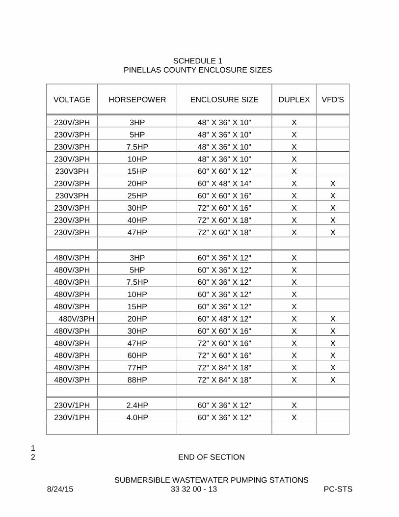
SUBMERSIBLE WASTEWATER PUMPING STATIONS 8/24/15 33 32 00 - 13 PC-STS
SCHEDULE 1
PINELLAS COUNTY ENCLOSURE SIZES
VOLTAGE HORSEPOWER ENCLOSURE SIZE DUPLEX VFD'S
230V/3PH 3HP 48" X 36" X 10" X 230V/3PH 5HP 48" X 36" X 10" X 230V/3PH 7.5HP 48" X 36" X 10" X 230V/3PH 10HP 48" X 36" X 10" X 230V3PH 15HP 60" X 60" X 12" X 230V/3PH 20HP 60" X 48" X 14" X X 230V3PH 25HP 60" X 60" X 16" X X 230V/3PH 30HP 72" X 60" X 16" X X 230V/3PH 40HP 72" X 60" X 18" X X 230V/3PH 47HP 72" X 60" X 18" X X
480V/3PH 3HP 60" X 36" X 12" X 480V/3PH 5HP 60" X 36" X 12" X 480V/3PH 7.5HP 60" X 36" X 12" X 480V/3PH 10HP 60" X 36" X 12" X 480V/3PH 15HP 60" X 36" X 12" X
480V/3PH 20HP 60" X 48" X 12" X X 480V/3PH 30HP 60" X 60" X 16" X X 480V/3PH 47HP 72" X 60" X 16" X X 480V/3PH 60HP 72" X 60" X 16" X X 480V/3PH 77HP 72" X 84" X 18" X X 480V/3PH 88HP 72" X 84" X 18" X X
230V/1PH 2.4HP 60" X 36" X 12" X 230V/1PH 4.0HP 60" X 36" X 12" X
1 END OF SECTION 2
GRAVITY SEWERS 7/07/15 33 33 01 - 1 PC-STS
SECTION 33 33 01 1 2
GRAVITY SEWERS 3 4
5 PART 1 - GENERAL 6 7 1.01 SCOPE OF WORK 8 9
A. The Work includes furnishing all plant, labor, tools, equipment, materials, and 10 performing all operations in connection with construction of sanitary sewers and 11 appurtenant structures, including excavation, trenching, backfilling and 12 appurtenant work as required, or as directed. 13
14 1.02 Material Depth Limitations 15 16
A. Pipe materials used for gravity sewers shall be subject to the depth limitations 17 indicated in accordance with the Standard Details. 18
19 PART 2 - PRODUCTS 20 21 2.01 MATERIALS 22 23
A. All gravity sewer pipe and appurtenant materials used in the Pinellas County 24 Sewer System shall be as specified in the latest version of the Pinellas 25 County Utilities Material Specification Manual at the time of plan approval. 26
27 PART 3 - EXECUTION 28 29 3.01 CONSTRUCTION 30
31 A. Order of Work 32 33
1. The Engineer reserves the right to specify which sewer lines will receive 34 priority in construction. In general, however, the work will be from the 35 lower end of the sewer towards the upper end of the sewer. 36
37 B. Maintenance of Existing Sewerage Facilities 38 39
1. It is the responsibility of the Contractor to maintain operation of the 40 existing sewerage facilities during construction and repair work. The 41 Contractor shall be responsible for providing any equipment required to 42 maintain operation of service during construction. Any damage done to 43 any existing sewer pipe or structure is to be immediately repaired to a 44 condition equal to, or better than, its original condition. 45
46

GRAVITY SEWERS 7/07/15 33 33 01 - 2 PC-STS
C. Location and Grade of Sewers 1 2
1. The line and the grade of the sewer, as well as the location of manholes, 3 and all other appurtenances, shall be as shown on the Plans or, as 4 directed by the Engineer. The grade line as given on the Plans indicates 5 the grade of the invert of the sewer pipe. 6
7 D. Cutting Gravity Sewer Pipe 8 9 1. Cutting ductile iron pipe shall be field cut with a power saw. No impact 10
cutting is permitted. The spigot end of pipe thus cut shall be filed or 11 ground to form a bevel. 12
13 2. Cutting PVC sewer pipe may be field cut using hand or power saws in 14
accordance with the manufacturer's recommendations. The raw spigot 15 end thus formed shall be filed to remove gasket damaging burrs and to 16 form a standard bevel. 17
18 E. Laying Gravity Sewers 19
20 1. Cut sheets for complete sections of the gravity sewers, as designated by 21
the Engineer, shall be submitted by the Contractor to the Engineer for 22 approval at least two days prior to construction. Each run of gravity 23 sewer shall be represented on a separated cut sheet. 24
25 2. Installation of ductile iron pipe shall conform to the procedures outlined 26
in "A Guide for the Installation of Ductile Iron Pipe" which is available 27 from the Ductile Iron Pipe Research Association. All ductile iron pipe is 28 to be encased in green polyethylene material, conforming to the 29 requirements of the County’s Materials Specification Manual. 30 Polyethylene film shall be supplied in tube form suitable for use in 31 Installation Method 'A' per AWWA C105. 32
33 3. Installation of PVC pipe shall be per ASTM D-2321 and UNI-B-5. 34 35 4. Trench excavation shall be as specified in Section 31 23 33, Excavation 36
and Backfill for Pipes. 37 38
5. Each pipe shall be laid true to line and grade so as to form a close 39 concentric joint with the adjoining pipe, preventing offsets in the flow line. 40 The trench bottom shall form a solid base for the entire length of pipe 41 and shall be capable of supporting the full weight of the pipe and backfill 42 material. The pipe bells shall not bear against the solid bottom of the 43 ditch. Sewers will be inspected with mirrors at intervals during 44 construction and corrected, if necessary, before backfill. 45
46
GRAVITY SEWERS 7/07/15 33 33 01 - 3 PC-STS
6. All wye units, stubs, or other fittings placed in lines for future 1 connections, or services, shall have the open bell tightly plugged using 2 pipe manufacturer=s recommended watertight plug. All plugs shall be 3 capable of withstanding 4 psi internal air test pressure, yet permit easy 4 removal for future use. 5
6 7. The open ends of all pipelines shall be kept securely plugged at the end 7
of each day's work and at any other time when any operation is being 8 carried out which might permit foreign materials, rock, dirt, etc. to enter 9 the pipe. Pipelines shall be thoroughly flushed out upon their completion 10 and when directed by the Engineer. 11
12 F. Joining Gravity Sewer Pipe 13 14
1. Gravity sewer pipe having factory fabricated joints shall be joined 15 together in strict accordance with the manufacturer's specifications. The 16 surface shall be wiped free of dust, dirt, gravel, or other foreign materials 17 before joining. The spigot end shall be centered on grade into the bell 18 end of the last downstream length of pipe, and properly seated. 19
20 2. When seating pipe with a pry, lever, or other approved device, care shall 21
be taken to protect the pipe end from damage. Ends damaged in any 22 manner shall be cause for rejection of the pipe. 23
24 G. Repair and Replacement Construction 25 26
1. All repair and replacement work shall conform to standards specified for 27 new construction wherever applicable, or as specified in the Repair 28 Specifications. 29
30 H. Removal of Existing Pipe 31 32
1. Existing pipe no longer in service that is removed from the system shall 33 be disposed of properly by the Contractor. Openings in manholes, 34 sewer lines, or wye branches remaining in place shall be properly 35 plugged and sealed so as to eliminate any possibility of infiltration at the 36 point of separation. All pieces of broken pipe shall be removed from the 37 trench before backfill operations commence. Backfill of the trench shall 38 be as specified in Section 31 23 33 - Excavation and Backfill for Pipes. 39 Inspection of structures remaining in place shall be made before backfill. 40
41 3.02 INSPECTIONS OF LINES AND MANHOLES 42 43
A. Inspection of completed lines and manholes shall be scheduled within a 44 reasonable time after construction or when required by the Engineer. Before 45

GRAVITY SEWERS 7/07/15 33 33 01 - 4 PC-STS
scheduling an inspection, the Contractor shall prepare the lines by cleaning and 1 flushing. Manholes shall be clean, finished and free of leaks. 2
3 B. Manholes shall be on a true and uniform grade. The inverts shall have a 4
smooth steel troweled finish. All benches shall be uniformly sloping. The 5 frames shall be tight and properly set in mortar on solid masonry. The invert, 6 benches and adjacent pipe shall be free of splattered mortar. All required 7 interior lining or paint shall be kept intact. Manhole frames shall be adjusted to 8 grade with the covers and frames cleaned and free of mortar and asphaltic 9 mixtures. All precast manhole seams shall be filled with an approved asphaltic 10 compound. 11
12 C. Pipe between manholes shall be true to line and grade. Dips and sags with 13
one inch or more of trapped water shall be cause for rejection. Inspection shall 14 be by mirror and sunlight and shall be followed by television inspection at the 15 Contractor's/Developer's expense. Air testing may be required also at the 16 Contractor's/Developer's expense. Contractor shall provide personnel to assist 17 with inspections. 18
19 D. The Contractor shall provide Pinellas County Utilities with a Television 20
Inspection of the completed gravity sewers in accordance with the following: 21 22
1. Shall be performed by a NASSCO PACP Certified Operator who will use 23 software that is compatible with Granite XP latest version software to 24 NASSCO PACP Standards. 25
26 2. Shall be submitted as digital media that includes video and data base file 27
in PACP format and include a printed copy of the PACP television 28 inspection log. 29
30 3. Shall perform a manhole inspection and provide a completed NASSCO 31
Manhole Inspection form latest version for each manhole that is 32 connected to the sewer being inspected. 33
34 4. All pertinent data recorded in audio on the media to include: 35 36
a. Subdividion name and phase number. 37 b. Manhole numbers (these numbers must match manhole numbers on 38
“as built” drawings). 39 c. Date 40 d. Size and material of pipe 41 e. Service connection locations, right or left 42 f. All distances between manholes 43 g. Locations of suspected and obvious pipe deficiencies (i.e., bad joints, 44
breaks or leaks etc) 45 46

GRAVITY SEWERS 7/07/15 33 33 01 - 5 PC-STS
5. PVC pipe shall have a deflection test using a seven and one-half percent 1 (go-no-go) test mandrel of appropriate size, which shall be visible on 2 video at all times. 3
4 6. The printed NASSCO PACP television report (indicating manhole 5
numbers) which will accompany the media. This written report must 6 include: 7
8 a. Manhole numbers (these numbers must match manhole numbers 9
on "as-built" drawings). 10 b. Service connection locations, right or left. 11
c. Reference to service connection locations out of manholes. 12 d. Locations of suspected and obvious pipe deficiencies (i.e., bad 13
joints, breaks or leaks, etc.). 14 e. Depth of each manhole. 15 f. Actual measured distance (on ground) between manholes. 16 17
7. All visual and television inspections shall be completed and approved by 18 Pinellas County Utilities after the road base has been constructed but 19 prior to the placing of any asphalt. 20
21 8. Television Inspection Media must clearly show details of structural 22
defects, misalignments and infiltration. 23 24 9. For detailed requirements for Television Inspection see Section 33 01 32 25
Sanitary Sewer Cleaning and Televising. 26 27
E. All known or indicated breaks shall be repaired by the Contractor regardless of 28 the test allowances. Faulty sections of sewer lines or manholes rejected by the 29 Engineer shall be removed and re-laid by the Contractor. Sunken manholes 30 will not be accepted. 31
32 3.03 SERVICE CONNECTIONS - WYE UNITS AND SERVICE PIPE 33 34
A. In new sewer construction, D.I.P. and PVC service connections shall be made 35 by means of a wye or tee. All joints connected to the wye unit shall remain 36 flexible. Service connections on existing mains shall be made using a sewer 37 saddle approved in the County’s Materials Specification Manual. 38
39 B. All new sewer service connections shall have a continuous looped trace wire 40
consisting of one (1) 14-gauge minimum solid copper or one (1) 12- gauge 41 copper clad steel tracer wires taped to the top center of the pipe from the 42 cleanout to the main line and back to the cleanout in accordance with the 43 Pinellas County Standard Details. Tracer wire shall be in accordance with the 44 County’s Materials Specifications Manual. 45
46

GRAVITY SEWERS 7/07/15 33 33 01 - 6 PC-STS
C. Service pipe for all properties shall be laid to the property line and plugged, as 1 shown on the Standard Details. All ends of service lines shall be marked by a 2 permanent stake and where sidewalks or curbs are located nearby, by a 3 chiseled mark cut in the sidewalk or curb. Service pipe shall have a protective 4 cover of not less forty-two (42) inches under all roads and thirty-six (36) inches 5 at all property lines. Inspection of service pipe shall be made before backfill. 6 Service pipe shall have a visibly good line and grade. Shallow service shall be 7 laid by using a four foot hand level with proper shim attached to one end. 8
9 10 D. In cases of extra depth where service pipe cannot be laid on a continuous 11
grade to the property line, the Contractor shall then furnish all materials and 12 construct risers as shown on the Plans. When pipe cannot be adequately 13 supported on undisturbed earth, it shall be supported on a concrete cradle. No 14 payment will be made for concrete required to correct conditions resulting from 15 faulty construction methods or negligence. 16
17 18 19 3.04 SERVICE RECONNECTIONS 20 21
A. Service reconnections require adapters for all joints that will not connect 22 properly with ordinary factory joints. Approved pipe cutting methods shall be 23 used to cut any pipe required for the connection. All cut pipe will be ground and 24 smoothed to remove snags and sharp edges. No mortar or collars shall be 25 used on reconnections unless specifically approved by the Engineer. 26
27 3.05 JOINING NEW PIPE TO OLD PIPE 28 29
A. Joining polyvinyl chloride pipe to existing vitrified clay pipe requires an adapter 30 approved in the County’s Materials Specification Manual for all joints that will 31 not connect properly with ordinary factory joints. Approved pipe cutting 32 methods must be used to cut any pipe required for the connection. All cut pipe 33 shall be ground and smoothed to remove snags and sharp edges. No mortar 34 or collars shall be used for such connections unless approved by the Engineer. 35
36 3.06 CLEAN-OUTS 37
38 A. Clean-outs shall be constructed in accordance with the Standard Details at 39
locations as shown on the Plans. 40 41 3.07 JOINING PIPE TO MANHOLES OR OTHER STRUCTURES 42 43
A. All manhole connection holes shall be core drilled with a maximum hole 44 diameter not to exceed one and a half times the pipe diameter. 45
46

GRAVITY SEWERS 7/07/15 33 33 01 - 7 PC-STS
B. Approved standard groutable PVC-to-manhole fitting approved in the County’s 1 Materials Specification Manual, or a flexible rubber boot may also be used at 2 the manhole connection. The boot shall be manufactured of neoprene or 3 isoprene compounds formulated and tested to resist deterioration due to 4 sewage, hydrogen sulfide, oils, fats, greases, petroleum products and 5 by-products. The connection at the manhole wall shall be flexible and 6 water-tight. Any annular space inside the manhole at the connection shall be 7 filled with approved caulking material or joint filler. 8
9 C. Stubouts for future mains shall be constructed at the locations and to the 10
elevations shown on the Plans. The manhole benches shall be constructed to 11 direct flows from all shown manhole inlets smoothly to the outlet. Stubouts 12 shall be plugged with bricks and mortar per the detail shown on the Plans. 13
14 D. Pipe connections to existing manholes shall be made so that finished work will 15
conform, as nearly as possible, to the essential requirements for new manhole 16 construction, as specified above. Drop connections on existing manholes shall 17 be strengthened by use of eight #6 pins, placed around the drop elbow and tee, 18 or inside PVC drops may be used. 19
20 3.08 WATER MAIN STORM DRAIN CROSSINGS 21 22
A. In all cases where sanitary sewer mains cross water mains, or storm sewers with 23 a minimum clear distance between the sanitary sewer and the water main or 24 storm sewer of less than twelve (12) inches, the sanitary sewer shall be ductile 25 iron pipe for a distance of ten feet on either side of the point of crossing. No pipe 26 joint shall occur within ten (10) feet of the crossed water main. 27
28 29
END OF SECTION 30
SANITARY SEWAGE FORCE MAINS AND APPURTENANCES
8/24/15 33 34 00 - 1 PC-STS
SECTION 33 34 00 1 2
SANITARY SEWAGE FORCE MAINS AND APPURTENANCES 3 4 5 PART 1 - GENERAL 6 7 1.01 SCOPE OF WORK 8 9
A. The Contractor shall furnish all plant, labor, materials, equipment and tools 10 and perform all operations in connection with the construction of the 11 sanitary sewage mains and appurtenances, including excavation, 12 trenching, backfilling, testing, clearing and clean-up. 13
14 1.02 MAINTAINING SERVICE AND SHUT DOWNS 15 16
A. The Contractor's attention is called to the fact that the existing system 17 must be kept in operation at all times. Where connections are made to 18 existing mains or other shutdowns are necessary, permission must be 19 obtained and arrangements must be made with the Utilities Department 20 for removing from service those mains that will be affected. Shutdowns 21 must be held to a minimum in both number and duration. Bypass 22 pumping and hauling operations may be required to interrupt service. 23
24 B. No valve or other control device on the existing system shall be operated 25
by the Contractor without first obtaining approval from the Utilities 26 Department. The Contractor shall, at least forty-eight (48) hours in 27 advance, notify citizens subject to interruption of service by means of door 28 hangers or any other approved method of the starting time and duration of 29 such interruption. 30
31 1.03 SUBMITTALS 32 33
A. Unless waived by the Engineer, cut sheets for the entire force main shall 34 be submitted by the Contractor to the Engineer for approval at least two 35 days prior to construction. This requirement will not relieve the Contractor 36 of the responsibility to accurately record the "as-built" locations (horizontal 37 and vertical) of piping, valving and appurtenances. Contractor shall 38 submit to the County the Continuity Testing Results per Section 3.04 Item 39 6.g. 40
41 1.04 LAYING PIPE 42
43 A. All roads and curbs shall be installed prior to force main installation. On a 44
road where there is no curb, the paving must be done prior to installing the 45 force main. Any deviation from this must be approved in writing by the 46

SANITARY SEWAGE FORCE MAINS AND APPURTENANCES
8/24/15 33 34 00 - 2 PC-STS
Pinellas County Engineer or his designated representative. In any case, 1 force mains will not be accepted or tested until curb and/or roads are 2 compete, thus preventing possible relocation or adjusting and retesting of 3 newly installed pipes. 4 5
B. All joints, fittings and other appurtenances shall not be covered until 6 inspected by the Pinellas County Inspector. Non-compliance will require 7 excavation of all joints and fittings. 8 9
C. The pipe and fittings shall be constructed as shown on the approved 10 Plans. All pipe four inches and larger in diameter may be deflected, but 11 not bent. PVC pipe two inches in diameter may be bent around cul-de-12 sacs that have a radius of thirty-seven (37) feet or larger if the trench is left 13 open until the Pinellas County Inspector is onsite to document that this 14 guideline is fully complied with. The use of fittings not shown on the 15 "Contractor Copy" construction Plan must have the prior concurrence of 16 the Pinellas County Inspector. 17
18 1.05 ABANDONMENT OF EXISTING MAINS BEING TAKEN OUT OF SERVICE 19 20
A. In general, pipe six inches and smaller abandoned within Pinellas County 21 rights-of-way shall be capped at both ends and abandoned in place. 22 Grouting is not required unless specifically required by the Engineer or the 23 County. 24
25 B. Abandoned pipes eight inches and larger shall be filled with grout or 26
flowable fill unless otherwise directed by the County or the Engineer. 27 28 C. Pipe abandoned in rights-of-way owned by municipalities other than 29
Pinellas County shall be subject to the requirements of the agency having 30 jurisdiction. 31
32 D. All pipes shall be abandoned in a manner which results in the abandoned 33
pipeline not being pressurized. 34 35 PART 2 – PRODUCTS 36 37 2.01 GENERAL 38 39
A. Materials, equipment and supplies furnished and permanently 40 incorporated into the Project shall be of first quality in every respect, shall 41 be constructed and finished to high standards of workmanship, and shall 42 be the product of an approved reputable manufacturer. Material shall be 43 suitable for the service intended, shall reflect modern design and 44 engineering and shall be fabricated in a first-class workmanlike manner. 45 All materials, equipment and supplies shall be new and shall have not 46

SANITARY SEWAGE FORCE MAINS AND APPURTENANCES
8/24/15 33 34 00 - 3 PC-STS
been in service at any time previous to installation, except as required in 1 tests or incident to installation. 2
3 B. Materials and construction pertaining to restoration and construction of 4
roads and structures shall be in accordance with the latest edition of 5 Florida Department of Transportation (DOT) Standard Specifications for 6 Road and Bridge Construction or as called for on the Plans. 7
8 C. All ductile iron or cast iron pipe, fittings and valves are to be encased in 9
green polyethylene material, conforming to ASTM specification D-1248, 10 with a minimum 8 mil thickness, taped and free of dirt in accordance with 11 the latest edition of AWWA C105. Polyethylene film shall be supplied in 12 tube form suitable for use in Installation Method 'A' as defined in AWWA 13 C105. 14
15 D. All piping and appurtenances shall be color coded green with the 16
exception of ductile iron pipe. That shall be encased in green 17 polyethylene wrap, or if not available, encased in clear polywrap and shall 18 be marked by means of three four-inch wide painted green lines along the 19 length of the pipe at opposite locations around the pipe. 20
21 E. All PVC piping and ductile iron mains partially constructed of PVC or 22
HDPE between valves shall be installed with locator wires, as specified 23 below. 24
25 F. Force mains shall be buried with green metallic locator tape. All locater 26
tape shall be placed twelve (12) inches above buried pipe. 27 28 G. No glued joints will be allowed. Mechanical restrainers are the only 29
acceptable method of restraint. 30 31 2.02 MATERIALS 32 33
A. All pipe and appurtenant materials used in the Pinellas County Sewer 34 System shall be as specified in the latest version of the Pinellas County 35 Utilities, Material Specification Manual at the time of plan approval. 36
37 PART 3 - EXECUTION 38 39 3.01 HANDLING 40
41 A. All materials, unless otherwise directed, shall be unloaded as nearby as 42
possible to the location of installation by the Contractor. Materials shall be 43 handled with care to avoid damage. 44
45
SANITARY SEWAGE FORCE MAINS AND APPURTENANCES
8/24/15 33 34 00 - 4 PC-STS
B. Materials shall be lifted by hoists or slid or rolled on skidways in such 1 manner as to avoid shock. Under no circumstances shall materials be 2 dropped. Pipe handled on skidways must not be allowed to roll against 3 pipe already on the ground. The Contractor shall be responsible for the 4 safe handling of all materials. Damaged materials shall not be installed. 5
6 C. All materials found during the progress of work to have flaws, cracks, or 7
other defects will be rejected by the Engineer regardless of whether or not 8 it has been installed and shall be replaced by and at the expense of the 9 Contractor. 10
11 D. All PVC pressure pipe, upon delivery to the site and until such time as it is 12
placed in the trench, shall be shielded from the weather and direct sunlight 13 to prevent pipe deterioration. 14
15 E. Materials shall not be stacked or placed under materials in such a manner 16
that damage could result. 17 18 F. Slings, hooks, or tongs used for lifting shall be padded in such a manner 19
as to prevent damage to exterior surfaces, interior linings and 20 components. If any part of the coating, lining or components is damaged, 21 the repairs or replacement shall be made by the Contractor at his expense 22 and in a manner satisfactory to the Engineer prior to attempting 23 installation. 24
25 G. In the event that materials supplied by the County are defective, the 26
Contractor shall notify the Engineer immediately so arrangements can be 27 made for replacing such devices. 28
29 3.02 FIELD LAYOUT AND MODIFICATIONS 30
31 A. The Contractor, unless directed otherwise, shall be responsible for setting 32
construction layout stakes and/or offsets required to complete the 33 designated work. The Contractor shall insure that those stakes and/or 34 offsets are protected and any re-staking due to work stoppage shall be 35 included and no additional compensation to the Contractor will be made. 36
37 B. The Engineer has the right to make any modifications as he deems 38
necessary due to field conditions, conflicts with other utilities or to protect 39 other properties. 40
41 3.03 EXCAVATION, ALIGNMENT AND GRADE 42 43
A. Trench excavation and backfill shall be in accordance with Specification 44 31 23 33, Excavation and Backfill for Pipes. 45
46
SANITARY SEWAGE FORCE MAINS AND APPURTENANCES
8/24/15 33 34 00 - 5 PC-STS
B. All mains shall be laid and maintained at the required lines and grades 1 with fittings, valves and appurtenances at the described locations. All pipe 2 shall be laid to the depth as shown on the Plans, or when a depth is not 3 indicated, with a minimum cover of thirty (30) inches outside of the 4 roadway, and thirty-six (36) inches under the roadway. Grade lines shall 5 be set by the Contractor. The tolerance of such grades shall not be more 6 than that specified on the drawings. When no tolerance is indicated a 7 tolerance of 0.5 foot shall be used. All other realignments must be 8 approved by the Engineer. The Contractor shall have suitable survey 9 equipment on the site at all times. 10
11 C. The Work shall at all times progress with caution so as to prevent damage 12
to underground obstructions both known and unknown. Should an 13 obstruction not shown on the Plans be encountered, the Engineer shall be 14 immediately notified and he shall be responsible for alteration to the plan 15 should realignment be necessary. The Contractor shall notify the 16 Engineer far enough in advance to allow the realignment to be 17 accomplished by deflection in the pipe joints. 18
19 3.04 LAYING AND JOINING BURIED FORCE MAINS 20 21
A. General 22 23
1. Prior to installation, all pipe shall be inspected for defects and all 24 lump or excess coatings shall be removed. The inside of the bell 25 and outside of the spigot shall be cleaned prior to joining of all pipe. 26 Caution shall be taken to prevent damage to the pipe during 27 lowering into the trench. Caution shall be taken to prevent foreign 28 matter from entering the pipe during installation. The Engineer may 29 require covering of the end of the pipe to prevent debris from 30 entering. No debris, tools, clothing or other material shall be placed 31 in the pipe. 32
33 2. After placement in the trench the spigot end of the pipe shall be 34
centered in the bell and the pipe shall be driven home and then 35 brought to the proper line and grade by tamping approved backfill 36 material under it, except for the bell. Joint deflection shall not 37 exceed manufacturer's limit. 38
39 3. During the time that the pipe is in the trench but no work is in 40
progress, the end shall be closed by a water-tight plug. This shall 41 include the noon hour, as well as overnight. If there is water in the 42 trench upon beginning work, this plug shall remain in place until the 43 trench has been pumped dry, unless otherwise approved by the 44 Engineer. 45
46
SANITARY SEWAGE FORCE MAINS AND APPURTENANCES
8/24/15 33 34 00 - 6 PC-STS
4. Standard plugs shall be inserted into all dead end pipes, tees or 1 crosses; spigot ends shall be capped; flanged ends shall have blind 2 flanges, or sheet metal or plywood caps. Plugs installed for 3 pressure testing shall be fully secured and restrained to withstand 4 the test pressure. 5
6 5. Where plugging is required because of Contract division or phasing 7
for later connection, the ends of such lines shall be equipped with a 8 permanent type cast iron or ductile iron plug/cap or blind flange with 9 or without a blowoff cock, as shown on the Drawings. Installation 10 or removal of such plugging shall be considered incidental to the 11 work and no payment shall be expected for this work by the 12 Contractor. 13
14 6. Tracer Wire For PVC, HDPE and Non-Continuous Ductile Iron 15
Force Mains. 16 17
a. Tracer wire shall be installed on all mainline pipe. Mainline 18 pipe installed by open cut method shall have two (2) 14-19 gauge minimum solid copper or two (2) 12-gauge copper-20 clad steel tracer wires taped to the top center of the pipe. 21 Mainline pipe installed by horizontal directional drill shall 22 have two (2) 12-gauge copper-clad steel tracer wires 23 installed with the pipe. All tracer wire shall be as specified in 24 the material specification manual. 25
26 b. The locator wires shall have colored insulation matching the 27
type of service provided in the main and be acceptable for 28 direct burial. 29
30 c. All splices of the wires shall be made with watertight 31
connections per material specification manual. 32 33
d. The wires shall each be continuous throughout the project. 34 35
e. The wire is to be tied to all valves, tees and elbows 36 37 f. The locator wires shall be brought up into all valve boxes 38
with enough slack provided to extend 10 to 12-inches out of 39 each box and installed as shown in the Standard Details. 40
41 g. Contractor shall perform a 12-volt DC electrical continuity 42
test on each of the wires. No more than one volt of loss per 43 1000 feet of mainline pipe will be acceptable. The locator 44 wire system shall pass the 12-volt DC electrical continuity 45 test for at least one wire prior to final acceptance of the 46

SANITARY SEWAGE FORCE MAINS AND APPURTENANCES
8/24/15 33 34 00 - 7 PC-STS
pipeline. Any cuts or breaks in the wire shall be repaired by 1 the Contractor at his expense. 2
3 h. The locator wire shall be tested by the Contractor at the time 4
of pressure testing. If this test fails, the Contractor is 5 responsible for repairing the locator wire and the pressure 6 test will be reschedule when the wire will pass. 7
8 B. Pigging, Flushing and Cleaning 9 10
1. All mains shall be pigged, cleaned and flushed to remove all sand 11 and other foreign matter. The Contractor shall be responsible for 12 developing a pigging and flushing plan to be submitted to the 13 Project Representative for approval prior to pigging and flushing. 14 The Contractor shall dispose of all water used pigging and for 15 flushing without causing a nuisance or property damage, in 16 accordance with state and local requirements. Any permits or fees 17 required for the disposal of flushing water shall be the responsibility 18 of the Contractor. 19
20 2. Flushing water used by the Contractor shall be taken from an 21
approved metered source. The water utility will provide the meter 22 and designate the source. Potable and reclaimed flushing water 23 shall be at the Contractor’s expense. 24
25 a. Reclaimed water should be used for sanitary force mains. 26 27 b. Potable water can be used for all service types. 28
3. The cleaning of the new piping system shall be accomplished by 29 the controlled and pressurized passage of a series of hydraulic or 30 pneumatic polyurethane plugs of varying dimensions coatings, and 31 densities; which shall be selected by the pipe cleaning Contractor. 32 The Contractor shall provide a means to enter the pig into the 33 system, control and regulate flow, monitor flows and pressures, and 34 to remove the pig from the system. The Contractor shall maintain a 35 constant surveillance of the system and immediately report to the 36 proper authority any in-line problems encountered or any 37 malfunctions discovered in the piping system. A record of pig 38 models, sizes, styles, and other pertinent information shall be kept 39 by the Contractor and turned over to the County. 40
4. The Contractor shall furnish pig launching and retrieval equipment 41 to minimize additional valving, fittings and auxiliary water supplies. 42 Valves and blowoff assemblies, which are installed as part of the 43 project, shall be used as much as possible to minimize the number 44 of temporary ports required for proper flushing and cleaning. 45

SANITARY SEWAGE FORCE MAINS AND APPURTENANCES
8/24/15 33 34 00 - 8 PC-STS
5. All materials used shall be specifically manufactured for flushing 1 and cleaning pressure pipes, bends and valves. The pigs shall be 2 able to go through bends, open valves and fittings, and provide 3 adequate cleaning of the pipe. 4
6. Cost of Pigging Services- The cost to complete the requirements 5 under this section shall be included in the contract items provided in 6 the proposal sheet. There is no separate pay item for this work. 7
C. Jointing HDPE Pipe and Fittings 8 9
1. HDPE pipe shall be jointed by the butt-fusion process in 10 accordance with pipe manufacturer’s directions. Contractor shall 11 provide butt-fusion technicians who are trained and certified by the 12 P.E. pipe manufacturer to complete the project. The date of 13 technician certification shall not exceed 12 months before 14 commencing construction. 15
16 2. Butt-fusion means the butt-joining of the pipe by softening the 17
aligned faces of the pipe ends in a suitable apparatus and pressing 18 them together under controlled pressure. 19
20 3. The internal and external beads resulting from the butt-fusion 21
process shall be visible and examined for penetration 360 degrees 22 around the pipe diameter. 23
24 4. All fittings for HDPE pipe (4” and larger), except for D.I/HDPE 25
Mechanical Joint Adaptors, shall be ductile iron mechanical joint 26 fittings per material specification manual and shall be joined to the 27 pipe using a butt fused restrained mechanical joint adapter. 28
29 5. The D.I./HDPE mechanical joint adapter shall be connected to the 30
HDPE pipe by a heat-fused joint on one end, and connected to a 31 ductile iron pipe valve, or fitting with a mechanical joint on the other 32 end. 33
34 6. Solvent epoxy cementing, electro-fusion couplings and 35
mechanical joining with bolt on wrap around clamps or mechanical 36 joints with out an adapter shall not be used for connections. 37
38 7. The D.I./HDPE mechanical joint adaptor shall be connected to the 39
HDPE pipe by a heat-fused joint on one end, and connected to a 40 ductile iron pipe valve, or fitting with a mechanical joint on the other 41 end. 42
43 8. Short pieces of pipe between valves and fittings shall be DIP with 44
all joints restrained for sizes 3-inches and larger. For 2-inch, the 45

SANITARY SEWAGE FORCE MAINS AND APPURTENANCES
8/24/15 33 34 00 - 9 PC-STS
short pieces shall be brass or Sch. 80 with IP threads and DI, 1 HDPE or brass fittings and all joints restrained. 2
3 D. Jointing Push-On Ductile Iron and PVC Pipe and Fittings 4
5 1. The inside of the bell and the outside of the spigot end shall be 6
thoroughly cleaned to remove dirt, grit, oil or excess coatings and 7 other foreign matter. The rubber gasket shall be flexed inward and 8 inserted in the gasket recess of the bell socket. A thin film of 9 gasket lubricant shall be applied to either the inside surface of the 10 gasket or the spigot ends, care will be taken to avoid contact with 11 the ground. The joint shall be completed by forcing the plain end to 12 the bottom of the socket with a forked tool or jacking device or other 13 approved method. All pipe shall have depth mark prior to insertion. 14 Pipe cut in the field shall be filed to resemble the spigot end of 15 manufactured pipe. 16
17 2. When deflection is required the joint shall be completed prior to 18
setting the deflection. The deflection shall conform to applicable 19 AWWA Standards or manufacturer's recommendation with prior 20 Engineer's approval. 21
22 E. Jointing Mechanical Joint Pipe and Fittings 23
24 1. The inside of the socket, the outside of the spigot end and the 25
gland shall be thoroughly cleaned and or washed with an approved 26 solution to remove dirt, grit, oil or excess coatings and foreign 27 matter to improve gasket seating. The gland shall then be placed 28 on the plain end of the pipe with the lip extension toward the plain 29 end, followed by the gasket with the narrow edge of the gasket 30 toward the plain end of the pipe. The pipe shall be inserted into the 31 socket and the gasket pressed firmly and evenly into the gasket 32 recess. The joint shall be kept straight during the assembly and 33 any deflection required shall be done after the joint has been 34 assembled but prior to tightening the bolts. 35
36 F. Jointing Special Joint Ductile Iron Pipe and Fittings 37
38 1. Other special joint pipe shall be assembled or installed, per 39
manufacturer's recommendations, or directed by the Engineer. The 40 Contractor shall insure that the joint is thoroughly cleaned by 41 removing all dirt, oil, grit, excess coatings and foreign matter to 42 insure a tight joint. 43
44 3.05 TEMPORARY AND PERMANENT PLUGGING 45 46

SANITARY SEWAGE FORCE MAINS AND APPURTENANCES
8/24/15 33 34 00 - 10 PC-STS
A. Temporary plugging of pipes shall be performed at the time of construction 1 when the work is interrupted due to lunch breaks, end of shift or any other 2 reason that require work to stop for more than half an hour. 3
4 B. Permanent plugs shall be inserted into the bells of all dead-ends of pipe, 5
tees, or crosses and plain ends shall be capped. All plugs and caps shall 6 be properly restrained as called for on the Plans or Standard Details. 7
8 3.06 REMOVAL OF OUT OF SERVICE PIPE 9 10
A. Due to certain permit requirements, pipe that is to be removed from 11 service will have to be physically taken out of the ground. The limits of 12 pipe to be removed shall be specifically called for in the Plans or shall be 13 approved in writing by the Engineer. Any other removal not specifically 14 called for, shall be considered incidental to construction of other items in 15 the Contract and the Contractor will not receive compensation for such 16 work. 17
18 B. When removing pipe, the Contractor shall excavate a trench wide enough 19
to dislodge the pipe from the surrounding soil, and long enough to be able 20 to handle the pipe without causing any damage to nearby utilities, 21 structures or adjacent property. 22
23 C. The removed pipe, fitting and appurtenances will become the Contractor's 24
property and he shall be responsible for proper disposal and any required 25 permits thereof. 26
27 D. Refer to Specification 01 35 00, Special Project Procedures for removal of 28
asbestos cement (AC) pipe. 29 30 3.07 INSTALLATION OF PIPE UNDER DRIVEWAYS 31 32
A. At the Engineer's discretion, the Contractor will be required to auger pipes 33 under driveways, structures or trees to avoid removal or expensive 34 restoration of those structures. The Contractor will be allowed to utilize an 35 auger machine and to push or pull the carrier pipe into the bore without 36 the need of a casing. 37
38 B. The Contractor shall install the sewer water pipe within the bore hole on a 39
line and grade to allow connection to open cut piping adjacent to the bore 40 hole within pipe jointing alignment limits defined for the pipe in question. 41 The completed installation shall not result in settlement of soil under the 42 driveway. 43
44 3.08 INSTALLATION OF PIPE UNDER HIGHWAYS AND RAILROADS 45 46

SANITARY SEWAGE FORCE MAINS AND APPURTENANCES
8/24/15 33 34 00 - 11 PC-STS
A. The Contractor shall furnish and install protective steel pipe casings 1 and/or carrier pipe under highways/railroads in the pipe size, thickness, 2 length, location and details as shown on the Drawings and specified 3 herein. The Contractor's attention is particularly directed to the 4 requirements of the particular municipal or private owner or Department of 5 Public Works having jurisdiction over the highways/railroads whether 6 through permit, verbal or other directions. 7
8 B. The construction shall not be started until the necessary permits have 9
been obtained, a copy is at the job site, and proper notice and approval for 10 construction has been obtained from the owner of the highway/railroad 11 and the Engineer. 12
13 C. All necessary materials, equipment, labor and traffic protection devices 14
shall be on the job site before requesting permission to start the Work. 15 16
D. Steel casings and the installation thereof required for highway/railroad 17 crossings shall be in accordance with the standards and requirements of 18 the Florida Department of Transportation (FDOT) or railroads or AASHTO 19 Standards and the Specifications outlined herein. All work of this nature 20 shall be performed by qualified Subcontractors regularly engaged in that 21 type or work and shall be subject to approval by the Engineer. 22
23 E. All work shall be in accordance with Specification 33 05 20, Jacking and 24
Boring. 25 26
3.09 FITTINGS 27 28
A. All fittings shall be restrained by means of restraining devices such as 29 restrainer glands, restraining gaskets, etc. 30
31 B. Fittings shall be set and joined to the pipe and each type of joint as 32
specified for pipe. 33 34 C. Trenching and backfilling for all fittings shall also be in accordance with 35
Section 31 23 33, Excavation and Backfill for Pipes. 36 37 D. The use of thrust blocks in new lines is prohibited and shall only be limited 38
to areas in which a new fitting has been installed in an existing line and is 39 not feasible to restrain joints or when directed by the Engineer. 40
41 E. The use of "reverse dead-man" shall be as described under Standard 42
Details for dead-end valves or in circumstances that the Engineer deems it 43 necessary and shall be performed under his direction. 44
45 3.10 VALVES 46

SANITARY SEWAGE FORCE MAINS AND APPURTENANCES
8/24/15 33 34 00 - 12 PC-STS
1 A. Valves shall be set and joined to the pipe and each type of joint as 2
specified for pipe. 3 4 B. Trenching and backfilling for all valves shall also be in accordance with 5
31 23 33, Excavation and Backfill for Pipes. 6 7
C. Cast iron valve boxes shall be firmly supported, maintained centered and 8 plumb over the operating nut of the valve. Outside of paved areas, valve 9 boxes shall be set in a 2' x 2' x 6" thick concrete collar, along with a brass 10 ID tag, as shown on Standard Details. The box cover shall be flush with 11 the surface of the finished pavement. All force main valve box lids shall 12 be painted green and shall have the word “SEWER” cast in the lid. 13
14 D. All reasonable effort must be made to locate valves/valve boxes, back of 15
curb, in grass areas and at street corners, whenever possible. 16 17 E. Valve boxes in areas that will require sod at a later date must be left one 18
to two inches above existing grade (to allow for sod thickness). 19 20 F. All valves/boxes shall be located by means of a perpendicular 6" x 2' 21
green stripe across the curb. The distance from the back of the curb to 22 the valve will be stenciled on the curb with numbers four inches high, 23 painted green, by the Contractor. This information will be referenced on 24 the pavement, if no curbs are to be installed. All valve box tops shall be 25 painted green. All valves must be centered over the operating nut/wheel 26 and all valves, after being fully opened, will be backed off one-quarter turn 27 to prevent them from being jammed open. This procedure should take 28 place only after the main has passed pressure testing and has been 29 accepted by the County. 30
31 G. All dead end valves shall be restrained with a reverse deadman, per the 32
Standard Details. 33 34 H. Should the operating nut be more than three feet below the final grade, an 35
extension shall be supplied and installed by the Contractor. The extension 36 shall bring the nut to within twelve (12) inches of final grade. 37
38 39 40 41 I. Installation of Valves on Existing Force Mains 42
43 1. When installing valves in existing mains (cutting-in), the Contractor 44
shall insure that the pipe is kept clean at all times and no debris, 45 ground water, mud, oil, etc., will make their way into the pipe. 46
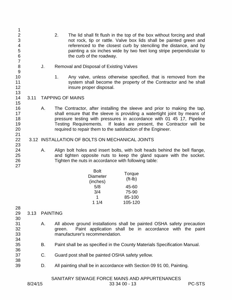
SANITARY SEWAGE FORCE MAINS AND APPURTENANCES
8/24/15 33 34 00 - 13 PC-STS
1 2. The lid shall fit flush in the top of the box without forcing and shall 2
not rock, tip or rattle. Valve box lids shall be painted green and 3 referenced to the closest curb by stenciling the distance, and by 4 painting a six inches wide by two feet long stripe perpendicular to 5 the curb of the roadway. 6
7 J. Removal and Disposal of Existing Valves 8
9 1. Any valve, unless otherwise specified, that is removed from the 10
system shall become the property of the Contractor and he shall 11 insure proper disposal. 12
13 3.11 TAPPING OF MAINS 14
15 A. The Contractor, after installing the sleeve and prior to making the tap, 16
shall ensure that the sleeve is providing a watertight joint by means of 17 pressure testing with pressures in accordance with 01 45 17, Pipeline 18 Testing Requirements. If leaks are present, the Contractor will be 19 required to repair them to the satisfaction of the Engineer. 20
21 3.12 INSTALLATION OF BOLTS ON MECHANICAL JOINTS 22
23 A. Align bolt holes and insert bolts, with bolt heads behind the bell flange, 24
and tighten opposite nuts to keep the gland square with the socket. 25 Tighten the nuts in accordance with following table: 26
27 Bolt
Diameter (inches)
Torque (ft-lb)
5/8 45-60 3/4 75-90 1 85-100
1 1/4 105-120 28 3.13 PAINTING 29 30
A. All above ground installations shall be painted OSHA safety precaution 31 green. Paint application shall be in accordance with the paint 32 manufacturer's recommendation. 33
34 B. Paint shall be as specified in the County Materials Specification Manual. 35
36 C. Guard post shall be painted OSHA safety yellow. 37
38 D. All painting shall be in accordance with Section 09 91 00, Painting. 39
SANITARY SEWAGE FORCE MAINS AND APPURTENANCES
8/24/15 33 34 00 - 14 PC-STS
1 3.14 PRESSURE TESTING 2 3
A. All sewage force mains shall be tested in accordance with Specification 4 01 45 17, Pipeline Pressure and Leakage Testing Requirements. 5
6 END OF SECTION 7

RECLAIMED WATER MAIN PIPING AND APPURTENANCES 7/07/15 33 35 01 - 1 PC-STS
SECTION 33 35 01 1 2
RECLAIMED WATER MAIN PIPING AND APPURTENANCES 3 4 5 PART 1 - GENERAL 6 7 1.01 SCOPE OF WORK 8 9
A. The Contractor shall furnish all plant, labor, materials, equipment and tools 10 and perform all operations in connection with the construction of the 11 effluent or reclaimed water mains and appurtenances, including 12 excavation, trenching, backfilling, testing, clearing and clean-up. 13
14 1.02 MAINTAINING SERVICE AND SHUT DOWNS 15 16
A. The Contractor's attention is called to the fact that the existing system 17 must be kept in operation at all times. Where connections are made to 18 existing mains or other shutdowns are necessary, permission must be 19 obtained and arrangements must be made with the Utilities Department 20 before removing from service those mains that will be affected. 21 Shutdowns must be held to a minimum in number and duration. 22
23 B. No valve or other control device on the existing system shall be operated 24
by the Contractor without first obtaining approval from the Utilities 25 Department. The Contractor shall, at least forty-eight (48) hours in 26 advance, notify citizens subject to interruption of service by means of door 27 hangers or any other approved method of the starting time and duration of 28 such interruption. 29
30 1.03 SUBMITTALS 31 32
A. Unless waived by the Engineer, cut sheets for the entire reclaimed water 33 main shall be submitted by the Contractor to the Engineer for approval at 34 least two days prior to construction. This requirement will not relieve the 35 Contractor of the responsibility to accurately record the "as-built" locations 36 (horizontal and vertical) of piping, valving and appurtenances. Contractor 37 shall submit to the County the Continuity Testing Results per Section 3.04 38 Item 6.g. 39
40 1.04 LAYING PIPE 41
42 A. All roads and curbs shall be installed prior to reclaimed water main 43
installation. On a road where there is no curb, the paving must be done 44 prior to installing the reclaimed water main. Any deviation from this must 45 be approved in writing by the Engineer or his designated representative. 46
RECLAIMED WATER MAIN PIPING AND APPURTENANCES 7/07/15 33 35 01 - 2 PC-STS
In any case, reclaimed water facilities will not be accepted or tested until 1 curb and/or roads are compete, thus preventing possible relocation or 2 adjusting and retesting of newly installed pipes. 3 4
B. All joints, fittings and other appurtenances shall not be covered until 5 inspected by the County Inspector. Non-compliance will require 6 excavation of all joints and fittings. 7 8
C. The pipe and fittings shall be constructed as shown on the approved 9 Plans. All pipe four inches and larger in diameter may be deflected, but 10 not bent. PVC pipe two inches in diameter may be bent around cul-de-11 sacs that have a radius of thirty-seven (37) feet or larger, if the trench is 12 left open until the County Inspector is onsite to document that this 13 guideline is fully complied with. The use of fittings not shown on the 14 "Contractor Copy" construction Plan must have the prior concurrence of 15 the County Inspector. 16 17
1.05 ABANDONMENT OF EXISTING MAINS BEING TAKEN OUT OF SERVICE 18 19
A. In general, pipe six inches and smaller abandoned within Pinellas County 20 rights-of-way shall be capped at both ends and abandoned in place. 21 Grouting is not required unless specifically required by the Engineer or the 22 County. 23
24 B. Abandoned pipes eight inches and larger shall be filled with grout or 25
flowable fill unless otherwise directed by the County or the Engineer. 26 27 C. Pipe abandoned in rights-of-way owned by municipalities other than 28
Pinellas County shall be subject to the requirements of the agency having 29 jurisdiction. 30
31 D. All pipes shall be abandoned in a manner which results in the abandoned 32
pipeline not being pressurized. 33 34 PART 2 – PRODUCTS 35 36 2.01 GENERAL 37 38
A. Materials, equipment and supplies furnished and permanently 39 incorporated into the Project shall be of first quality in every respect, shall 40 be constructed and finished to high standards of workmanship, and shall 41 be the product of an approved reputable manufacturer. Material shall be 42 suitable for the service intended, shall reflect modern design and 43 engineering and shall be fabricated in a first-class workmanlike manner. 44 All materials, equipment and supplies shall be new and not have been in 45
RECLAIMED WATER MAIN PIPING AND APPURTENANCES 7/07/15 33 35 01 - 3 PC-STS
service at any time previous to installation, except as required in tests or 1 incident to installation. 2
B. Materials and construction pertaining to restoration and construction of 3 roads and structures shall be in accordance with the latest edition of 4 Florida Department of Transportation (DOT) Standard Specifications for 5 Road and Bridge Construction or as called for on the Plans. 6
7 C. All ductile iron or cast iron pipe, fittings and valves and that portion of fire 8
hydrants that is underground, are to be encased in lavender polyethylene 9 material, conforming to the requirements of the County’s Materials 10 Specification Manual. Polyethylene film shall be supplied in tube form 11 suitable for use in Installation Method 'A' per AWWA C105. 12
13 D. All piping and appurtenances used shall be color coded lavender with the 14
exception of ductile iron pipe. That shall be encased in lavender 15 polyethylene wrap, or if not available, encased in clear polywrap and shall 16 be marked by means of three four-inch wide painted lavender lines along 17 the length of the pipe at opposite locations around the pipe. 18
19 E. All PVC piping and ductile iron mains partially constructed of PVC or 20
HDPE between valves shall be installed with locator wires as specified 21 below. 22
23 F. Reclaimed water mains shall be buried with purple metallic locator tape. 24
All locater tape shall be placed twelve (12) inches above buried pipe. 25 26 G. No glued joints will be allowed. Mechanical restrainers are the only 27
acceptable method of restraint. 28 29
2.02 MATERIALS 30 31
A. All pipe and appurtenant materials used in the Pinellas County Reclaimed 32 Water System shall be as specified in the latest version of the Pinellas 33 County Utilities Material Specification Manual at the time of Plan approval. 34
35 PART 3 - EXECUTION 36 37 3.01 HANDLING 38
39 A. All materials, unless otherwise directed, shall be unloaded as nearby as 40
possible to the location of installation by the Contractor. Materials shall be 41 handled with care to avoid damage. 42
43 B. Materials shall be lifted by hoists or slid or rolled on skidways in such 44
manner as to avoid shock. Under no circumstances shall materials be 45 dropped. Pipe handled on skidways must not be allowed to roll against 46
RECLAIMED WATER MAIN PIPING AND APPURTENANCES 7/07/15 33 35 01 - 4 PC-STS
pipe already on the ground. The Contractor shall be responsible for the 1 safe handling of all materials. Damaged materials shall not be installed. 2
C. All materials found during the progress of work to have flaws, cracks, or 3 other defects will be rejected by the Engineer regardless of whether or not 4 it has been installed and shall be replaced by and at the expense of the 5 Contractor. 6
7 D. All PVC pressure pipe, upon delivery to the site and until such time as it is 8
placed in the trench, shall be shielded from the weather and direct sunlight 9 to prevent pipe deterioration. 10
11 E. Materials shall not be stacked or placed under materials in such a manner 12
that damage could result. 13 14 F. Slings, hooks, or tongs used for lifting shall be padded in such a manner 15
as to prevent damage to exterior surfaces, interior linings and 16 components. If any part of the coating, lining or components is damaged, 17 the repairs or replacement shall be made by the Contractor at his expense 18 and in a manner satisfactory to the Engineer prior to attempting 19 installation. 20
21 G. In the event that materials supplied by the County are defective, the 22
Contractor shall notify the Engineer immediately so arrangements can be 23 made for replacing such devices. 24
25 3.02 FIELD LAYOUT AND MODIFICATIONS 26
27 A. The Contractor, unless directed otherwise, shall be responsible for setting 28
construction layout stakes and/or offsets required to complete the 29 designated Work. The Contractor shall insure that those stakes and/or 30 offsets are protected and any re-staking, due to work stoppage, shall be 31 included and no additional compensation to the Contractor will be made. 32
33 B. The Engineer has the right to make any modifications as he deems 34
necessary due to field conditions, conflicts with other utilities or to protect 35 other properties. 36
37 3.03 EXCAVATION, ALIGNMENT AND GRADE 38 39
A. Trench excavation and backfill shall be in accordance with Specification 40 31 23 33, Excavation and Backfill for Pipes. 41
42 B. All mains shall be laid and maintained at the required lines and grades 43
with fittings, valves and appurtenances at the described locations. All pipe 44 shall be laid to the depth as shown on the Plans, or when a depth is not 45 indicated, with a minimum cover of thirty (30) inches outside of the 46

RECLAIMED WATER MAIN PIPING AND APPURTENANCES 7/07/15 33 35 01 - 5 PC-STS
roadway, and thirty-six (36) inches under the roadway. Grade lines shall 1 be set by the Contractor. The tolerance of such grades shall not be more 2 than that specified on the drawings. When no tolerance is indicated a 3 tolerance of 0.5 foot shall be used. All other realignments must be 4 approved by the Engineer. The Contractor shall have suitable survey 5 equipment on the site at all times. 6
7 C. The Work shall at all times progress with caution to prevent damage to 8
underground obstructions, both known and unknown. Should an 9 obstruction not shown on the Plans be encountered, the Engineer shall be 10 immediately notified and he shall be responsible for alteration to the Plan, 11 should realignment be necessary. The Contractor shall notify the 12 Engineer far enough in advance to allow the realignment to be 13 accomplished by deflection in the pipe joints. 14
15 3.04 LAYING AND JOINING BURIED RECLAIMED WATER MAINS 16 17
A. General 18 19
1. Prior to installation, all pipe shall be inspected for defects and all 20 lump or excess coatings shall be removed. The inside of the bell 21 and outside of the spigot shall be cleaned prior to joining of all pipe. 22 Caution shall be taken to prevent damage to the pipe during 23 lowering into the trench. Caution shall be taken to prevent foreign 24 matter from entering the pipe during installation. The Engineer may 25 require covering of the end of the pipe to prevent debris from 26 entering. No debris, tools, clothing or other material shall be placed 27 in the pipe. 28
29 2. After placement in the trench, the spigot end of the pipe shall be 30
centered in the bell and the pipe shall be driven home and then 31 brought to the proper line and grade by tamping approved backfill 32 material under it, except for the bell. Joint deflection shall not 33 exceed manufacturer's limit. 34
35 3. During the time that the pipe is in the trench, but no work is in 36
progress, the end shall be closed by a water-tight plug. This shall 37 include the noon hour, as well as overnight. If there is water in the 38 trench upon beginning work, this plug shall remain in place until the 39 trench has been pumped dry, unless otherwise approved by the 40 Engineer. 41
42 4. Standard plugs shall be inserted into all dead end pipes, tees or 43
crosses; spigot ends shall be capped; flanged ends shall have blind 44 flanges, or sheet metal or plywood caps. Plugs installed for 45
RECLAIMED WATER MAIN PIPING AND APPURTENANCES 7/07/15 33 35 01 - 6 PC-STS
pressure testing shall be fully secured and blocked to withstand the 1 test pressure. 2
3 5. Where plugging is required, because of Contract division or 4
phasing for later connection, the ends of such lines shall be 5 equipped with a permanent type cast iron or ductile iron plug/cap or 6 blind flange with or without a blowoff cock, as shown on the 7 Drawings. Installation or removal of such plugging shall be 8 considered incidental to the Work and no payment shall be 9 expected for this work by the Contractor. 10
11 6. Tracer Wire For PVC, HDPE and Non-Continuous Ductile Iron 12
Mainlines 13 14
a. Tracer wire shall be installed on all mainline pipe. Mainline 15 pipe installed by open cut method shall have two (2) 14-16 gauge minimum solid copper or two (2) 12-gauge copper-17 clad steel tracer wires taped to the top center of the pipe. 18 Mainline pipe installed by horizontal directional drill shall 19 have two (2) 12-gauge copper-clad steel tracer wires 20 installed with the pipe. All tracer wire shall be as specified in 21 the material specification manual. 22
23 b. The locator wires shall have colored insulation matching the 24
type of service provided in the main and be acceptable for 25 direct burial. 26
27 c. All splices of the wires shall be made with watertight 28
connections per material specification manual. 29 30
d. The wires shall each be continuous throughout the project. 31 32
e. The wire is to be tied to all valves, tees and elbows 33 34 f. The locator wires shall be brought up into all valve boxes 35
with enough slack provided to extend 10 to 12-inches out of 36 each box and installed as shown in the Standard Details. 37
38 g. Contractor shall perform a 12-volt DC electrical continuity 39
test on each of the wires. No more than one volt of loss per 40 1000 feet of mainline pipe will be acceptable. The locator 41 wire system shall pass the 12-volt DC electrical continuity 42 test for at least one wire prior to final acceptance of the 43 pipeline. Any cuts or breaks in the wire shall be repaired by 44 the Contractor at his expense. 45
46

RECLAIMED WATER MAIN PIPING AND APPURTENANCES 7/07/15 33 35 01 - 7 PC-STS
h. The locator wire shall be tested by the Contractor at the time 1 of pressure testing. If this test fails, the Contractor is 2 responsible for repairing the locator wire and the pressure 3 test will be reschedule when the wire will pass. 4
5 7. Tracer Wire for Long Side Services 6
7 d. Each long side service or any service over 40 feet shall have 8
one (1) locator wire duct taped to top center of pipe. 9 10 e. The locator wire shall have colored insulation matching the 11
type of service provided in the service and be acceptable for 12 direct burial. 13
14 f. All splices of the wire shall be made with watertight 15
connections per material specification manual. 16 17 g. The wire shall be continuous along the service line. 18 19 h. The locator wire shall have one end sealed off and buried 20
within 12-inches of the connection to the main with the other 21 end stubbed off in the service box with enough slack 22 provided to extend 10 to 12-inches out of each service box. 23
24 8.. Contractor shall perform a tone test on each long side service using 25
a wire and cable locator. The locator wire system shall pass the 26 tone test prior to final acceptance of the service line. Any cuts or 27 breaks in the wire shall be repaired by the Contractor at his 28 expense. 29
30 B. Pigging, Flushing and Cleaning 31 32
1. All mains shall be pigged, cleaned and flushed to remove all sand 33 and other foreign matter. The Contractor shall be responsible for 34 developing a pigging and flushing plan to be submitted to the 35 Project Representative for approval prior to pigging and flushing. 36 The Contractor shall dispose of all water used pigging and for 37 flushing without causing a nuisance or property damage, in 38 accordance with state and local requirements. Any permits or fees 39 required for the disposal of flushing water shall be the responsibility 40 of the Contractor. 41
42 2. Flushing water used by the Contractor shall be taken from an 43
approved metered source. The water utility will provide the meter 44 and designate the source. Potable and reclaimed flushing water 45 shall be at the Contractor’s expense. 46
RECLAIMED WATER MAIN PIPING AND APPURTENANCES 7/07/15 33 35 01 - 8 PC-STS
1 a. Reclaimed water should be used for reclaimed water mains. 2 3 b. Potable water can be used for all service types. 4
3. The cleaning of the new piping system shall be accomplished by 5 the controlled and pressurized passage of a series of hydraulic or 6 pneumatic polyurethane plugs of varying dimensions coatings, and 7 densities; which shall be selected by the pipe cleaning Contractor. 8 The Contractor shall provide a means to enter the pig into the 9 system, control and regulate flow, monitor flows and pressures, and 10 to remove the pig from the system. The Contractor shall maintain a 11 constant surveillance of the system and immediately report to the 12 proper authority any in-line problems encountered or any 13 malfunctions discovered in the piping system. A record of pig 14 models, sizes, styles, and other pertinent information shall be kept 15 by the Contractor and turned over to the County. 16
17 4. The Contractor shall furnish pig launching and retrieval equipment 18
to minimize additional valving, fittings and auxiliary water supplies. 19 Valves and blowoff assemblies, which are installed as part of the 20 project, shall be used as much as possible to minimize the number 21 of temporary ports required for proper flushing and cleaning. 22
23 5. All materials used shall be specifically manufactured for flushing 24
and cleaning pressure pipes, bends and valves. The pigs shall be 25 able to go through bends, open valves and fittings, and provide 26 adequate cleaning of the pipe. 27
28 6. Cost of Pigging Services- The cost to complete the requirements 29
under this section shall be included in the contract items provided in 30 the proposal sheet. There is no separate pay item for this work. 31
32 C. Jointing HDPE Pipe and Fittings 33 34
1. HDPE pipe shall be jointed by the butt-fusion process in 35 accordance with pipe manufacturer’s directions. Contractor shall 36 provide butt-fusion technicians who are trained and certified by the 37 P.E. pipe manufacturer to complete the project. The date of 38 technician certification shall not exceed 12 months before 39 commencing construction. 40
41 2. Butt-fusion means the butt-joining of the pipe by softening the 42
aligned faces of the pipe ends in a suitable apparatus and pressing 43 them together under controlled pressure. 44
45
RECLAIMED WATER MAIN PIPING AND APPURTENANCES 7/07/15 33 35 01 - 9 PC-STS
3. The internal and external beads resulting from the butt-fusion 1 process shall be visible and examined for penetration 360 degrees 2 around the pipe diameter. 3
4 4. All fittings for HDPE pipe (4” and larger), except for D.I/HDPE 5
Mechanical Joint Adaptors, shall be ductile iron mechanical joint 6 fittings per material specification manual and shall be joined to the 7 pipe using a butt fused restrained mechanical joint adapter. 8
9 5. The D.I./HDPE mechanical joint adapter shall be connected to the 10
HDPE pipe by a heat-fused joint on one end, and connected to a 11 ductile iron pipe valve, or fitting with a mechanical joint on the other 12 end. 13
14 6. Solvent epoxy cementing, electro-fusion couplings and 15
mechanical joining with bolt on wrap around clamps or mechanical 16 joints with out an adapter shall not be used for connections. 17
18 7. Short pieces of pipe between valves and fittings shall be DIP with 19
all joints restrained for sizes 3-inches and larger. For 2-inch, the 20 short pieces shall be brass or Sch. 80 with IP threads and DI, 21 HDPE or brass fittings and all joints restrained. 22
23 D. Jointing Push-On Ductile Iron, Steel and PVC Pipe 24
25 1. The inside of the bell and the outside of the spigot end shall be 26
thoroughly cleaned to remove dirt, grit, oil or excess coatings and 27 other foreign matter. The rubber gasket shall be flexed inward and 28 inserted in the gasket recess of the bell socket. A thin film of 29 gasket lubricant shall be applied to either the inside surface of the 30 gasket or the spigot ends, care will be taken to avoid contact with 31 the ground. The joint shall be completed by forcing the plain end to 32 the bottom of the socket with a forked tool or jacking device or other 33 approved method. All pipe shall have depth mark prior to insertion. 34 Pipe cut in the field shall be filed to resemble the spigot end of 35 manufactured pipe. 36
37 2. When deflection is required, the joint shall be completed prior to 38
setting the deflection. The deflection shall conform to applicable 39 AWWA Standards or manufacturer's recommendation, with prior 40 Engineer's approval. 41
42 E. Jointing Mechanical Joint Pipe and Fittings 43
44 1. The inside of the socket, the outside of the spigot end and the 45
gland shall be thoroughly cleaned and or washed with an approved 46
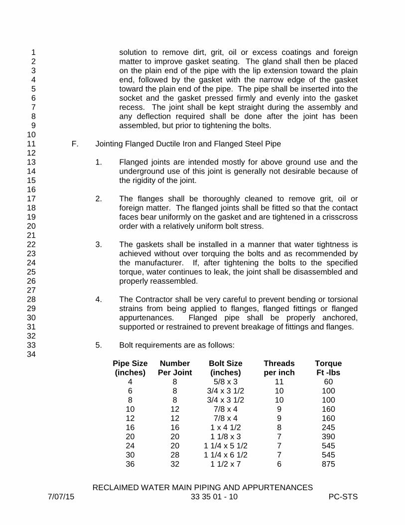
RECLAIMED WATER MAIN PIPING AND APPURTENANCES 7/07/15 33 35 01 - 10 PC-STS
solution to remove dirt, grit, oil or excess coatings and foreign 1 matter to improve gasket seating. The gland shall then be placed 2 on the plain end of the pipe with the lip extension toward the plain 3 end, followed by the gasket with the narrow edge of the gasket 4 toward the plain end of the pipe. The pipe shall be inserted into the 5 socket and the gasket pressed firmly and evenly into the gasket 6 recess. The joint shall be kept straight during the assembly and 7 any deflection required shall be done after the joint has been 8 assembled, but prior to tightening the bolts. 9
10 F. Jointing Flanged Ductile Iron and Flanged Steel Pipe 11 12
1. Flanged joints are intended mostly for above ground use and the 13 underground use of this joint is generally not desirable because of 14 the rigidity of the joint. 15
16 2. The flanges shall be thoroughly cleaned to remove grit, oil or 17
foreign matter. The flanged joints shall be fitted so that the contact 18 faces bear uniformly on the gasket and are tightened in a crisscross 19 order with a relatively uniform bolt stress. 20
21 3. The gaskets shall be installed in a manner that water tightness is 22
achieved without over torquing the bolts and as recommended by 23 the manufacturer. If, after tightening the bolts to the specified 24 torque, water continues to leak, the joint shall be disassembled and 25 properly reassembled. 26
27 4. The Contractor shall be very careful to prevent bending or torsional 28
strains from being applied to flanges, flanged fittings or flanged 29 appurtenances. Flanged pipe shall be properly anchored, 30 supported or restrained to prevent breakage of fittings and flanges. 31
32 5. Bolt requirements are as follows: 33
34 Pipe Size (inches)
Number Per Joint
Bolt Size (inches)
Threads per inch
Torque Ft -lbs
4 8 5/8 x 3 11 60 6 8 3/4 x 3 1/2 10 100 8 8 3/4 x 3 1/2 10 100
10 12 7/8 x 4 9 160 12 12 7/8 x 4 9 160 16 16 1 x 4 1/2 8 245 20 20 1 1/8 x 3 7 390 24 20 1 1/4 x 5 1/2 7 545 30 28 1 1/4 x 6 1/2 7 545 36 32 1 1/2 x 7 6 875
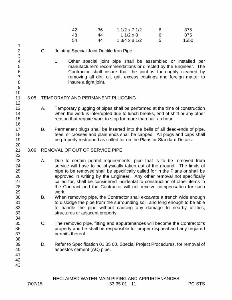
RECLAIMED WATER MAIN PIPING AND APPURTENANCES 7/07/15 33 35 01 - 11 PC-STS
42 36 1 1/2 x 7 1/2 6 875 48 44 1 1/2 x 8 6 875 54 44 1 3/4 x 8 1/2 5 1550
1 G. Jointing Special Joint Ductile Iron Pipe 2
3 1. Other special joint pipe shall be assembled or installed per 4
manufacturer's recommendations or directed by the Engineer. The 5 Contractor shall insure that the joint is thoroughly cleaned by 6 removing all dirt, oil, grit, excess coatings and foreign matter to 7 insure a tight joint. 8
9 10 3.05 TEMPORARY AND PERMANENT PLUGGING 11 12
A. Temporary plugging of pipes shall be performed at the time of construction 13 when the work is interrupted due to lunch breaks, end of shift or any other 14 reason that require work to stop for more than half an hour. 15
16 B. Permanent plugs shall be inserted into the bells of all dead-ends of pipe, 17
tees, or crosses and plain ends shall be capped. All plugs and caps shall 18 be properly restrained as called for on the Plans or Standard Details. 19
20 3.06 REMOVAL OF OUT OF SERVICE PIPE 21 22
A. Due to certain permit requirements, pipe that is to be removed from 23 service will have to be physically taken out of the ground. The limits of 24 pipe to be removed shall be specifically called for in the Plans or shall be 25 approved in writing by the Engineer. Any other removal not specifically 26 called for, shall be considered incidental to construction of other items in 27 the Contract and the Contractor will not receive compensation for such 28 work. 29
B. When removing pipe, the Contractor shall excavate a trench wide enough 30 to dislodge the pipe from the surrounding soil, and long enough to be able 31 to handle the pipe without causing any damage to nearby utilities, 32 structures or adjacent property. 33
34 C. The removed pipe, fitting and appurtenances will become the Contractor's 35
property and he shall be responsible for proper disposal and any required 36 permits thereof. 37
38 D. Refer to Specification 01 35 00, Special Project Procedures, for removal of 39
asbestos cement (AC) pipe. 40 41 42 43

RECLAIMED WATER MAIN PIPING AND APPURTENANCES 7/07/15 33 35 01 - 12 PC-STS
1 3.07 INSTALLATION OF PIPE UNDER DRIVEWAYS 2 3
A. At the Engineer's discretion, the Contractor will be required to auger pipes 4 under driveways, structures or trees to avoid removal or expensive 5 restoration of those structures. The Contractor will be allowed to utilize an 6 auger machine and to push or pull the carrier pipe into the bore without 7 the need of a casing. 8
9 B. The Contractor shall install the water pipe within the bore hole on a line 10
and grade to allow connection to open cut piping adjacent to the bore hole 11 within pipe jointing alignment limits defined for the pipe in question. The 12 completed installation shall not result in settlement of soil under the 13 driveway. 14
15 3.08 INSTALLATION OF PIPE UNDER HIGHWAYS AND RAILROADS 16 17
A. The Contractor shall furnish and install protective steel pipe casings 18 and/or carrier pipe under highways/railroads in the pipe size, thickness, 19 length, location and details as shown on the Drawings and as specified 20 herein. The Contractor's attention is particularly directed to the 21 requirements of the particular municipal or private owner or Department of 22 Public Works having jurisdiction over the highways/railroads, whether 23 through permit, verbal or other directions. 24
25 B. The construction shall not be started until the necessary permits have 26
been obtained, a copy is at the job site, and proper notice and approval for 27 construction has been obtained from the owner of the highway/railroad 28 and the Engineer. 29
30 C. All necessary materials, equipment, labor and traffic protection devices 31
shall be on the job site before requesting permission to start the Work. 32 33 D. Steel casings and the installation thereof required for highway/railroad 34
crossings shall be in accordance with the standards and requirements of 35 the Florida Department of Transportation (FDOT) or railroads or AASHTO 36 Standards and the Specifications outlined herein. All work of this nature 37 shall be performed by qualified Contractors regularly engaged in that type 38 or work and shall be subject to approval by the Engineer. 39
40 E. All work shall be in accordance with Specification 33 05 20, Jacking and 41
Boring. 42 43 44 45 46

RECLAIMED WATER MAIN PIPING AND APPURTENANCES 7/07/15 33 35 01 - 13 PC-STS
3.09 FITTINGS 1 2
A. All fittings shall be restrained by means of restraining devices such as 3 restainer glands, restraining gaskets, etc. 4
5 B. Fittings shall be set and joined to the pipe and each type of joint as 6
specified for pipe. 7 8 C. Trenching and backfilling for all fittings shall also be in accordance with 9
Section 31 23 33, Excavation and Backfill for Pipes. 10 11 D. The use of thrust blocks in new lines is prohibited and shall only be limited 12
to areas in which a new fitting has been installed in an existing line and is 13 not feasible to restrain joints or when directed by the Engineer. 14
15 E. The use of "reverse dead-man" shall be as described under Standard 16
Details for dead-end valves or in circumstances that the Engineer deems it 17 necessary and shall be performed under his direction. 18
19 3.10 VALVES 20 21
A. Valves shall be set and joined to the pipe and each type of joint as 22 specified for pipe. 23
24 B. Trenching and backfilling for all valves shall also be in accordance with 25
Specification 31 23 33, Excavation and Backfill for Pipes. 26 27
C. Cast iron valve boxes shall be firmly supported, maintained centered and 28 plumb over the operating nut of the valve Outside of paved areas, valve 29 boxes shall be set in a 2' x 2' x 6" thick concrete collar, along with a brass 30 ID tag, as shown in Standard Details. The box cover shall be flush with 31 the surface of the finished pavement. All box lids shall be painted 32 lavender and shall have the word “RECLAIMED WATER” OR 33 “RECLAIMED” cast in the lid. 34
35 D. All reasonable effort must be made to locate valves/valve boxes, back of 36
curb, in grass areas and at street corners, whenever possible. Valves 37 should be kept in clusters within two feet of the tee, when possible. 38
E. Valve boxes in areas that will require sod at a later date, must be left one 39 to two inches above existing grade (to allow for sod thickness). 40
41 F. All valves/boxes shall be located by means of a perpendicular 6" x 2' 42
lavender stripe across the curb. The distance from the back of the curb to 43 the valve will be stenciled on the curb with numbers four inches high, 44 painted lavender, by the Contractor. This information will be referenced 45 on the pavement if no curbs are to be installed. All valve box tops shall be 46

RECLAIMED WATER MAIN PIPING AND APPURTENANCES 7/07/15 33 35 01 - 14 PC-STS
painted lavender. All valves must be centered over the operating 1 nut/wheel and all valves, after being fully opened, will be backed off one-2 quarter turn to prevent them from being jammed open. This procedure 3 should take place only after the main has passed pressure testing and has 4 been accepted by the County. 5
6 G. All dead end valves shall be restrained with a reverse deadman, per the 7
Standard Details. 8 9 H. Should the operating nut be more than three feet below the final grade, an 10
extension shall be supplied and installed by the Contractor. The extension 11 shall bring the nut to within twelve (12) inches of final grade. 12
13 I. Installation of Valves on Existing Mains 14
15 1. When installing valves in existing mains (cutting-in), the Contractor 16
shall insure that the pipe is kept clean at all times and no debris, 17 ground water, mud, oil, etc. will make their way into the pipe. 18
19 2. The Contractor shall notify customers of reclaimed water service 20
shut-down and shall insure that such is held to a minimum. 21 22
3. The lid shall fit flush in the top of the box without forcing and shall 23 not rock, tip or rattle. Roadway boxes for bypass valves shall be 24 marked "BYPASS". Valve box lids shall be painted lavender and 25 referenced to the closest curb by stenciling the distance and by 26 painting a six inch wide by two feet long stripe perpendicular to the 27 curb of the roadway. 28
29 J. Removal and Disposal of Existing Valves 30
31 1. Any valve, unless otherwise specified, that is removed from the 32
System shall become the property of the Contractor and he shall 33 ensure proper disposal. 34
35 36
3.11 TAPPING OF MAINS 37 38
A. The Contractor, after installing the sleeve and prior to making the tap, 39 shall insure that the sleeve is providing a watertight joint by means of 40 pressure testing with pressures in accordance with Specification 01 45 17, 41 Pipeline Testing Requirements. If leaks are present, the Contractor will be 42 required to repair them to the satisfaction of the Engineer. 43
44 45 46

RECLAIMED WATER MAIN PIPING AND APPURTENANCES 7/07/15 33 35 01 - 15 PC-STS
3.12 SERVICE METERS AND ACCESSORIES 1 2
A. Unless specified to be furnished by the Contractor under a separate pay 3 item, all meters, reduced pressure devices, double check valves, etc., will 4 be supplied by the Utilities Department. The Contractor shall pick-up such 5 devices, where directed, and shall inspect them thoroughly and shall 6 insure that they are in proper working order. 7 8
B. The Contractor shall install meters, backflow devices, double check 9 valves, etc. at locations called for in the Plans, as sketched out or as 10 directed by the Engineer. No meter or accessory is to be installed outside 11 of the right-of-way unless easements have been secured or as specifically 12 directed by the Engineer. 13
14 C. When relocating meters, the Contractor shall insure that the meter is 15
operational. If the meter or accessories are damaged, he shall bring this 16 to the attention of the Engineer. Meter boxes shall be replaced, as well as 17 brass fittings and pipe inserts, and shall be considered incidental to the 18 cost of relocating meters. 19
20 D. All meter, backflow, reduced pressure device, etc., installations shall be 21
made in accordance with Pinellas County Utilities Department Standard 22 Construction Details. 23
24 3.13 SERVICE LINES AND SERVICE CASINGS 25 26
A. Service line casings shall be installed on all long side services. Casings 27 may be installed using the pneumatic bullet method, subject to the 28 requirements of the entity having jurisdiction for the roadway. 29 30
B. Service casings for one-inch services casings shall be Schedule 80 PVC 31 or SDR-9 HDPE two inches in diameter for single services three inches in 32 diameter for double services. 33
34 C. All casings shall be marked on both sides of the road with a six inch wide 35
lavender stripe running across the curb in the direction of the casing. A 36 single strand of lavender tracer wire shall be installed with the casing and 37 extend up the 2 x 4 that is required at the end of the casing. The 2 x 4 will 38 be six feet in length and painted lavender. 39
40 D. The depth to the top of the casings shall be thirty (30) inches to thirty-six 41
(36) inches. Casings that are installed deeper than thirty-six (36) inches 42 shall be removed and installed at the correct depth. Casings shall extend 43 a minimum of five feet beyond the existing back-of-curb or edge of 44 roadway. Exceptions to this requirement due to physical constraints shall 45 require prior approval by the Engineer. 46
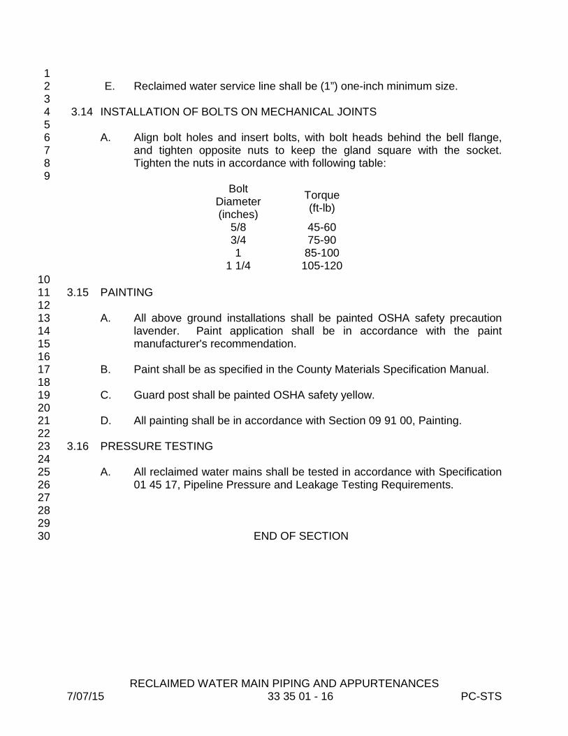
RECLAIMED WATER MAIN PIPING AND APPURTENANCES 7/07/15 33 35 01 - 16 PC-STS
1 E. Reclaimed water service line shall be (1”) one-inch minimum size. 2 3
3.14 INSTALLATION OF BOLTS ON MECHANICAL JOINTS 4 5
A. Align bolt holes and insert bolts, with bolt heads behind the bell flange, 6 and tighten opposite nuts to keep the gland square with the socket. 7 Tighten the nuts in accordance with following table: 8
9 Bolt
Diameter (inches)
Torque (ft-lb)
5/8 45-60 3/4 75-90 1 85-100
1 1/4 105-120 10 3.15 PAINTING 11 12
A. All above ground installations shall be painted OSHA safety precaution 13 lavender. Paint application shall be in accordance with the paint 14 manufacturer's recommendation. 15
16 B. Paint shall be as specified in the County Materials Specification Manual. 17
18 C. Guard post shall be painted OSHA safety yellow. 19 20 D. All painting shall be in accordance with Section 09 91 00, Painting. 21 22 3.16 PRESSURE TESTING 23 24
A. All reclaimed water mains shall be tested in accordance with Specification 25 01 45 17, Pipeline Pressure and Leakage Testing Requirements. 26
27 28 29
END OF SECTION 30

SANITARY SEWER STRUCTURES 7/07/15 33 39 00 - 1 PC-STS
SECTION 33 39 00 1 2
SANITARY SEWER STRUCTURES 3 4 5 PART 1 - GENERAL 6 7 1.01 SCOPE OF WORK 8 9 A. The Work includes furnishing all plant, labor, tools, equipment, materials, 10
end performing all operations in connection with construction of sanitary 11 sewers and appurtenant structures, including excavation, trenching, 12 backfilling and appurtenant work as required, or as directed. 13
14 1.02 RELATED DOCUMENTS 15 16 A. Specification 33 33 01, Gravity Sewers 17 18 B. Specification 31 23 34, Excavation and Backfill for Structures 19 20 PART 2 – PRODUCTS 21 22 2.01 MATERIALS 23
24 A. General 25 26
1. All manholes shall be precast concrete unless prior approval for an 27 alterative material is given by the County. 28
29 B. Concrete 30
31 1. Concrete for cradles shall conform to Specification 03 10 01, 32
Concrete and Concrete Materials of these Specifications and shall 33 develop a minimum 2,500 psi compressive strength at twenty-eight 34 (28) days. 35
36 C. Brick 37
38 1. Where brick manholes are specifically called for, brick shall be hard, 39
solid common clay brick meeting the requirements for latest ASTM 40 C-32 (sewer brick), Grade MA. 41
42 D. Mortar 43
44 1. Mortar for manholes shall consist of one part Portland Type II 45
cement, two to three parts fine sand mixed with water for proper 46
SANITARY SEWER STRUCTURES 7/07/15 33 39 00 - 2 PC-STS
consistency. Lime shall not be used in mortar for manholes. 1 Commercially prepared mortar mixes, or expanding grout, shall not 2 be used. Admixtures to mortar or commercial fast-setting cements 3 shall not be used without approval of the Engineer. 4
5 2.02 MANHOLES 6 7 A. Slabs for Brick Manholes 8 9
1. Slabs shall be 3,750 psi/28 day concrete with a wood float finish. 10 Reinforcement shall consist of #4 bars on eight inch centers, both 11 ways, with one and one-half-inches of cover over the bar mat and 12 three inches between earth and re-bar. 13
14 2. Brick manholes less than twelve (12) feet deep shall have a slab 15
depth of eight inches. Manholes twelve (12) feet or deeper shall have 16 a slab depth of twelve (12) inches. Slabs for standard manholes, 17 shall be no less than six feet square. Slabs for Type A manholes, 18 shall be a minimum of five feet square. Slabs for drop manholes shall 19 be of sufficient size to support the manhole and the entire drop 20 structure. 21
22 3. Slabs shall be located accurately so that manhole or manhole and 23
drop assembly will be centered on slab. All slabs shall be installed at 24 a grade that will allow clearance under the bells of the pipe. All 25 slabs shall be solidly installed on 3/4-inch bedding stone which has 26 been compacted against firm undisturbed ditch bottom. Depth of 27 bedding stone shall be a minimum of six inches, or as directed by the 28 Engineer. 29
30 4. The Contractor shall request an inspection of reinforcing steel for all 31
slabs poured on the job. 32 33
5. The Contractor shall submit a copy of all concrete truck delivery 34 receipts to the Engineer. 35
36 6. If slabs for manholes are to be supplied by a commercial precast firm, 37
the Contractor shall advise the Engineer sufficiently in advance so 38 that inspection may be initiated at the precast yard. 39
40 B. Precast Manholes 41
42 1. Precast, reinforced concrete manholes shall have tongue and groove 43
interlocking joints. Inverts shall be formed as specified herein. Shop 44 drawings shall be submitted and approved by the Engineer prior to 45 placing order with supplier. 46
SANITARY SEWER STRUCTURES 7/07/15 33 39 00 - 3 PC-STS
a. Precast reinforced concrete manhole risers, grade rings and 1 tops shall conform as to materials, design, and fabrication with 2 the requirements of ASTM, C-478. The concrete shall consist 3 of 4,000 psi/28 day, Type II Portland Cement. The walls for 4 standard manholes shall be no less than six inches thick. All 5 precast manhole parts are to be free of fractures, honeycomb, 6 and other defects of concrete. Cones shall be concentric. 7
8 b. Precast manholes shall consist of a base unit with openings 9
for the sewer pipe, riser units of various lengths to build the 10 manhole up to the required depth and concentric cones. The 11 minimum height of the shortest riser shall be twelve (12) 12 inches. 13
14 C. Fiberglass Manholes 15
16 1. Fiberglass manholes shall be as specified in the County’s Materials 17
Specification Manual. 18 19
D. Manhole Frames and Covers 20 21
1. All frames and covers are to be U.S. Foundry and Manufacturing 22 Corporation #195W, with a one hundred sixty-five (165) pound cover, 23 or approved equal. All mating surfaces shall be machined for proper 24 fit. All covers are to be stamped "Pinellas County Sanitary Sewer" 25 with the year of construction. All manhole covers shall have two 26 watertight pick holes. 27
28 PART 3 - EXECUTION 29 30 3.01 EXCAVATION AND BACKFILL 31 32 A. Excavation and backfill for manholes shall be per Specification 31 23 34, 33
Excavation and Backfilling for Structures. 34 35 3.02 MANHOLE CONSTRUCTION 36 37 A. Brick Manholes 38 39
1. Where required, manholes shall be constructed of brick masonry with 40 cast iron frames and covers. Mortar shall be properly proportioned, 41 thoroughly mixed, and used immediately. Any mortar entering the 42 initial set, requiring additional water or heating, shall be discarded. 43 Bricks will be laid radially and pressed into the mortar spread on the 44 previous course. Each brick will be pressed against the adjoining 45 brick so that inside vertical corners touch. The mortar shall totally fill 46

SANITARY SEWER STRUCTURES 7/07/15 33 39 00 - 4 PC-STS
all space between bricks. The inside wall of the manhole shall be 1 kept wiped clean of excess mortar. Excess mortar on the outside of 2 the manhole wall shall be kept troweled smooth or cut off. Corbels 3 are to be concentric, and built in twelve (12) courses, unless 4 otherwise specified. The exterior of the manhole shall be plastered to 5 a 5/8-inch thickness, and shrinkage cracks shall be sealed by 6 brushing before the final set. Risers between corbels and cast iron 7 frames shall be limited to twelve (12) inches. The exterior plastered 8 surface of the manholes shall be coated with an approved asphaltic 9 waterproofing material. When outside drops are constructed on 10 manholes, the drop shall be entirely supported by the slab. The drop 11 stack may be formed by brick and poured with concrete, or built up 12 with brick and mortar. Memphis Tees shall be used in the drop 13 structures. All drop manholes shall have the inside surfaces coated 14 as specified for precast manholes. 15
16 B. Precast Manholes 17 18
1. Any modifications necessary to adapt the units to conform to the 19 locations and grades shown, or required, shall be made without 20 additional compensation. It shall be the responsibility of the 21 Contractor to assure that all manhole inlets are provided at the proper 22 locations and elevations to accommodate the actual field 23 requirements without additional compensation. 24
25 2. All requirements for manhole and drop manhole construction as 26
previously specified which are applicable to precast manhole 27 construction shall be considered as being contained herein. 28
29 3. Slabs for precast manholes shall extend a minimum of six inches 30
beyond the outside face of the manhole wall. 31 32
4. All slabs for precast drop manholes shall be of sufficient size to 33 entirely support the drop structure. Slabs shall have the minimum 34 thickness shown in the Standard Details. 35
36 5. Manhole Units 37
38 a. All exposed interior surfaces and the tongue and groove ends 39
of each unit shall be sand blasted and brushed clean, and 40 immediately thereafter, completely coated with a protective 41 coating of not less than 15 mils of manhole coating per 42 Material Specification Manual. The coating shall be applied in 43 strict accordance with the manufacturer's recommendations. 44
45

SANITARY SEWER STRUCTURES 7/07/15 33 39 00 - 5 PC-STS
b. All exterior surfaces shall be brushed clean and, immediately 1 thereafter, completely coated with a protective coating of not 2 less than 15 mils of approved coating. The coating shall be 3 applied in strict accordance with manufacturer’s 4 recommendations. 5
6 c. The interior and exterior paint shall be intact and continuous. 7
Any chips or holidays shall be patched using two coats of 8 approved coatings and used according to manufacturer 9 instructions. 10
11 d. Top and bottom ends of riser or sections shall be perfectly 12
formed so that continuous and uniform contact is possible 13 around the entire joint. Malformed joints shall be rejected. 14
15 6. Installation 16
17 a. All slabs or bottom sections shall be installed at a grade that 18
will allow clearance under the bells of the pipe. All slabs or 19 bottom sections shall be solidly installed on 3/4-inch bedding 20 stone which has been compacted against firm undisturbed 21 ditch bottom. Depth of bedding stone will be as directed by 22 the Engineer. 23
24 b. The tongue and groove ends of each unit shall be primed with 25
Ram-nek primer and allowed to dry. Immediately before 26 placing the next unit, the joints shall receive a coating of Ram-27 nek. Enough plastic material shall be placed in the joint to 28 squeeze a bead of excess material out of the joint insuring a 29 completely sealed joint. 30
31 c. The top of the cone shall be set between two and one-half 32
inches and fourteen and one-half (14 1/2) inches below the 33 bottom of the manhole cover frame. It is the intent of the 34 Specifications to provide a minimum of two and one-half 35 inches to accommodate future grade changes without 36 disturbing the manhole. Where the distance between the 37 bottom of the manhole cover frame and the top of the cone is 38 greater than fourteen and one-half (14 1/2) inches, 12-inch 39 riser units shall be used to bring the top of the cone to within 40 the limits specified. 41
42 d. The annular space between the sewer pipe and the opening in 43
the manhole shall be grouted with Portland cement mortar and 44 wiped or collared to insure a watertight joint. Invert channels 45 shall be formed after the manhole is set by one of the following 46
SANITARY SEWER STRUCTURES 7/07/15 33 39 00 - 6 PC-STS
methods: Build up with brick and mortar, or lay a full section of 1 sewer pipe through manhole and cut out the top half. The 2 manhole floor outside of the channels shall be made smooth 3 and sloped toward the channels on a slope of two inches, per 4 foot. 5
6 C. Inverts 7 8
1. Invert channels shall be constructed smooth and semicircular, 9 conforming to the inside of adjacent sewer section. The mortared 10 invert channel shall have a steel trowel finish. Changes in direction of 11 flow shall be made in a smooth curve of as large a radius as possible. 12 Changes in size and grade shall be made gradually and smoothly. 13 Whenever possible, inverts shall be formed with a full section of pipe 14 laid through the manhole with the top half of the pipe cut out. 15 Benches shall be built up solidly with concrete or brick and mortar 16 and shall be sloping to the invert. All inside drops shall have a flume 17 constructed to channel flow into the invert. Standard drop manholes 18 shall be built whenever the inside drop exceeds twenty-four (24) 19 inches. All pipe entering the manhole must be trimmed flush with the 20 walls. All exposed sharp edges of pipe shall be wiped smooth with 21 mortar. 22
23 D. Type A Manholes 24 25
1. Manholes four feet or less in depth shall be constructed in accordance 26 with the details shown on the Plans. 27
28 E. Standard Manholes 29 30
1. Standard manholes shall be constructed in accordance with the 31 details shown on the Plans. 32
33 F. Drop Manholes 34
35 1. Drop manholes shall be constructed in accordance with details 36
shown on the Plans. 37 2. Special drop manholes may be required at points where force mains 38
connect to gravity sewers above the flow line of the manhole. The 39 special bowl drop shall be constructed in accordance with the 40 Standard Details. 41
42 G. Concrete Cradles 43
44 1. Concrete cradles shall be constructed at the location shown on the 45
Plans or as directed. They shall conform to the details shown on the 46
SANITARY SEWER STRUCTURES 7/07/15 33 39 00 - 7 PC-STS
Plans, or may, under special conditions, be modified as directed by 1 the Engineer. 2
3 H. Fiberglass Lined Manholes 4
5 1. The properly installed liners shall not fail under H-20 dynamic wheel 6
load applied vertically. All fiberglass products shall be subject to 7 OCFC Visual Inspection Standards, prior to installation. Fiberglass 8 manhole liners shall be constructed on the base slab, as specified, 9 and shall be encased by brick masonry, or pre-cast as previously 10 specified. 11
12 2. Any pipe entering through the manhole walls with an invert equal to, 13
or higher than the benches will be sealed all around to the interior 14 walls by use of fiberglass patching kit. There shall be no mortar 15 exposed above bench level, except the stack. 16
17 I. Epoxy Impregnated Membrane Lined Manhole 18
19 1. Where specifically required by the Plans, manhole lining shall be 20
installed using an epoxy impregnated membrane. Specific 21 membrane thickness and epoxy density, and attributes, shall be as 22 shown on the Plans or Standard Details, or as specified by the 23 Engineer. 24
25 J. Removal of Existing Manholes 26 27
1. The Contractor shall remove, as indicated on the Plans, the entire 28 manhole structure including all walls, base slab, frame and cover. 29 The Contractor shall install a new manhole immediately after removal 30 of the existing manhole or immediately backfill and compact the 31 excavation with sand to a one hundred (100) percent maximum 32 density, as determined by the methods contained in the State of 33 Florida Department of Transportation Standard Specifications for 34 Road and Bridge Construction, latest edition. 35
36 2. Should the Contractor elect to backfill the excavation prior to the 37
installation of the new manhole, the road surface shall be patched 38 with asphalt in accordance with Section 32 12 01 – Stabilized 39 Roadway and Asphalt Paving, and shall be maintained in satisfactory 40 condition until such time as the new manhole is installed. 41
42 K. Adjustment of Manhole Frames and Covers 43
44 1. Manhole frames and covers shall be adjusted to pavement grade during 45
road resurfacing by addition or removal of successive courses of brick 46

SANITARY SEWER STRUCTURES 7/07/15 33 39 00 - 8 PC-STS
masonry. Where required by the Engineer, height adjustment inserts of 1 continuous rings of a type, as directed by the Engineer, shall be installed 2 in the frame/cover assembly. 3 4
2. Manhole frame and covers shall be adjusted to finished ground elevation 5 in non-pavement areas by addition or removal of successive courses of 6 brick masonry. Where required by the Engineer, height adjustment 7 inserts of continuous rings of a type, as directed by Engineer, shall be 8 installed in the frame/cover assembly. 9
10 3.03 INSPECTION OF MANHOLES 11 12
A. Inspection of completed lines and manholes shall be as specified in Section 13 33 33 01, Gravity Sewers. 14
15 16
END OF SECTION 17

WASTEWATER PUMP STATION SCADA REMOTE TELEMETRY UNIT (RTU)
8/24/15 40 95 01 - 1 PC-STS
SECTION 40 95 01 1 2
WASTEWATER PUMP STATION SCADA 3 REMOTE TELEMETRY UNIT (RTU) 4
5 6
PART 1 - GENERAL 7 8 1.01 DESCRIPTION 9 10
A. The Contractor shall provide, program, and install SCADA Remote 11 Terminal Units (RTU’s) as described within this Specification. 12
13 B. The RTU unit shall be interfaced with the pump station Pump Control 14
Panel and be configured to monitor the pump station status, and provide 15 control as noted within this Specification. 16
17 C. The RTU shall be programmed and configured by an authorized agent of 18
Motorola. 19 20 D. The RTU shall be configured to interface with the County’s existing 21
SCADA system in place, via Field Interface Units (FIU’s). 22 23 E. The Contractor shall provide programming, required by the WonderWare 24
HMI software, to interface with the RTU/FIU at the central SCADA system. 25 26 F. The County will provide existing sample screens for each SCADA panel 27
type. 28 29 1.02 QUALITY CONTROL 30
31 A. It is essential that only qualified personnel be allowed to work on the 32
RTU/SCADA system. To maintain system warranties and system security 33 it is imperative that only qualified SCADA contractors provide new 34 equipment and integration services. At a minimum, the RTU/SCADA 35 contractor must have the following qualifications: 36 37 1. State of Florida Electrical Contractor license to insure proper 38
electrical installation of the RTU. 39 40 2. Motorola Certified MOSCAD Solutions Provider indicating that the 41
contractor was Motorola trained on MOSCAD to insure proper 42 software configuration, application, and functionality of the RTU. 43
44 45 46
WASTEWATER PUMP STATION SCADA REMOTE TELEMETRY UNIT (RTU)
11/29/12 40 95 01 - 2 PC-STS
1 1.03 WARRANTY 2
3 A. The manufacturer shall furnish a minimum eighteen (18) month warranty 4
against defects in materials and workmanship covering parts and labor on 5 all electrical control components to include breakers, starters, selector 6 switches, pilot lights (excluding lamps), and transformers. The RTU/PC 7 will have a two-year warranty to include lightning damage. The 8 manufacturer will supply all material and labor to repair or replace failed 9 components at no cost to the County. 10
11 1.04 OPERATION AND MAINTENANCE MATERIALS 12 13
A. The Contractor shall deliver to the County the following documentation 14 with the Final Pay Request: 15
16 1. A complete RTU schematic and wiring diagram, with bill of 17
materials, on CD, AutoCAD, latest version. 18 19 2. Four maintenance manuals with the above drawings and 20
manufacturer’s maintenance literature bound in three ring binders. 21 22
3. A laminated copy of the schematic and wiring diagram will be 23 permanently affixed to the interior side of the exterior enclosure 24 door using RTV silicone. 25
26 PART 2 - PRODUCTS 27 28 2.01 REMOTE TERMINAL UNIT (RTU) 29 30
A. The County’s SCADA consists of remote terminal units, Field Interface 31 Units/Front End Processors (FIUs/FEP’s) and multiple redundant SCADA 32 computers operating with WonderWare Human Machine Interface (HMI) 33 software. Lift station remote monitoring and control communications are 34 provided through the County’s 800MHZ trunked radio system. 35
36 B. A complete RTU shall be installed and integrated with the station Pump 37
Control Panel, and HMIs. All RTU components will be provided in a single 38 enclosure. The RTU shall be compatible with and provide all the 39 functionality and features of the County’s existing wireless SCADA 40 System. The RTU will be Motorola MOSCAD Ace with Motorola SCADA 41 RTU software. It is the responsibility of the RTU/SCADA supplier to 42 provide all of the specified RTU hardware, software, functionality, 43 installation, and startup services as detailed below. 44
45
WASTEWATER PUMP STATION SCADA REMOTE TELEMETRY UNIT (RTU)
11/29/12 40 95 01 - 3 PC-STS
C. The pump control panel shall also operate independently of the 1 SCADA/telemetry system in the event of failure of the remote 2 communications link. 3
4 2.02 FUNCTIONALITY 5
6 A. The RTU shall provide local automatic monitoring from float switches, 7
bubbler systems, transducers, ultrasonic level sensor inputs, and dry 8 contacts. Inputs shall be provided for both digital inputs and analog (4-9 20ma DC) transducers. Simultaneous monitoring of analog and digital 10 level sensing devices shall be supported where the analog level sensing 11 device shall be primary. The RTU shall contain routines for detecting 12 sensor failures and utilize the alternate level sensing device(s). Analog 13 sensors and specific float alarms shall be reported to the Central HMIs if 14 floats operate out of sequence. In all cases, the RTU shall be supplied 15 with an input for an emergency “High Level Float”. Battery backup power 16 shall be provided so that monitoring is maintained during Utility power 17 failures. Specific functions may vary based upon the Pump Station Type 18 as noted within this specification. 19
20 B. Local manual pump control is provided by “Hand-Off-Auto-Remote” 21
(HOAR) switches located in the Pump Control Panel. In the absence of 22 RTU power or in the case of RTU failure, the pump motor starters shall 23 remain operational in the HAND position. In no case shall the RTU have 24 the capability to operate or override the pumps in the HAND, OFF or 25 AUTO positions. HOAR switches shall be reported back to the Central 26 HMIs when a switch has been set in the HAND, OFF, or AUTO positions. 27
28 C. The capability to control a local alarm system consisting of an alarm horn 29
and light shall be provided. Inputs and outputs shall be provided for this 30 functionality. Under a “High Level”, or other specified alarm condition, the 31 alarm shall be reported to the Central HMIs. The alarm horn and light may 32 be silenced either locally from the pump control panel or remotely from 33 Central HMIs via the RTU. If the alarm condition clears, the alarm silence 34 control shall be restored. 35
36 D. The RTU shall be configured to control two to four pumps. 37
38 E. The RTU shall report elapsed runtime and number of starts for each pump 39
to the Central HMIs. These values shall be stored in the RTU. In the case 40 of failure of the RTU, these values shall be restored without user 41 intervention. The Central HMIs shall have the ability to individually reset 42 each pump’s starts and/or runtimes without loss of data. On demand 43 reports shall be made available for detailed and average starts and 44 runtimes of each pump and station. 45
WASTEWATER PUMP STATION SCADA REMOTE TELEMETRY UNIT (RTU)
11/29/12 40 95 01 - 4 PC-STS
F. The RTU shall be provided with routines to detect individual pump fault 1 alarms and shall report these alarms to the Central HMIs. Alarms shall 2 report when a pump is called to run but fails to start, or when a pump is 3 called to turn off but continues to run, and when a pump is running and 4 shuts off before it is called to turn off. An additional spare input point shall 5 be provided for each pump for use with an external pump fault indicator 6 such as seal fail or thermal. These alarms shall be individually reported 7 back to the redundant Central HMIs. 8
9 G. RTU configuration parameters shall be adjustable locally and remotely 10
from the Central HMIs. These functions shall be logged with a time stamp 11 at the Central HMIs. 12
13 H. The capability to interface with a phase monitor and associated inputs and 14
outputs shall be provided with the RTU. The phase monitor shall detect 15 loss of phase, phase reversal, and phase-to-phase voltages. Utility line 16 voltages shall not be wired directly to the RTU. Upon loss of phase, phase 17 reversal, low or high line voltages; the RTU shall send an alarm to the 18 Central HMIs. Phase voltages from phase A to phase B, from phase C to 19 phase B and from Phase A to phase C on three-phase systems and 20 voltages from L1 to neutral, from L2 to neutral and from L1 to L2 on single-21 phase 240VAC systems shall be reported to the Central HMIs. 22
23 I. A 4-20ma DC analog input for each pump shall be provided with the RTU 24
for monitoring motor amps or VFD output speed. The RTU shall average 25 individual motor amperage and report both instantaneous and average 26 amperage to the Central HMIs. 27
28 J. A fail-safe input shall be provided indicating intrusion. Upon loss of this 29
signal, or a series of devices providing this signal, the RTU shall report an 30 alarm to the Central HMIs. Battery backup power shall be provided for this 31 input. 32
33 K. If the lift station has generator power backup, two inputs, one indicating 34
generator power is online and the second indicating a commercial power 35 phase loss detection thru a user installed phase monitor on the line side of 36 the power feed from the utility, shall be provided and reported to the 37 Central HMIs. Battery backup power shall be provided for these inputs. 38
39 L. The RTU shall have the capability of locally verifying communication 40
status with a FIU/FEP. Pressing the SILENCE button five times in 41 succession shall blink the alarm light five times in succession if 42 communications is successful, in both directions, with a FIU/FEP. 43
44 45 46

WASTEWATER PUMP STATION SCADA REMOTE TELEMETRY UNIT (RTU)
11/29/12 40 95 01 - 5 PC-STS
1 2.03 CONSTRUCTION 2 3
A. The RTU shall be housed in a dust-proof and waterproof NEMA 4X, Type 4 304, 14 Gauge stainless steel enclosure powder coated white, with a 304 5 stainless steel, lockable three-point handle-type latching mechanism. All 6 exterior hardware and hinges shall be stainless steel. 7
8 B. A 14 gauge aluminum back-panel will be provided to mount all electrical 9
control devices. All interior electrical control components mounted on the 10 back-panel will be secured using stainless steel machine screws 8-32 11 minimum size. Heavier items including the RTU, control power 12 transformer and items in excess of ten (10) pounds will be secured with 13 1/4”-20 stainless steel machine screws. Screw anchor nuts will be 14 permanently installed in the sub-panel using cadmium plated steel knurled 15 threaded inserts AKV Model AKS7 or equal. No self-tapping or sub-panel 16 tapped screws will be used. 17
18 C. All wiring to the control devices within the RTU panel will be harnessed 19
and permanently attached to the panel using welded 8-32 studs and stud 20 mounted cable ties. Stick on tie wrap fasteners are not acceptable. 21 Wiring will be supported every eight inches minimum. This panel will be 22 grounded via a 10-32 stud located in the bottom hinged side and bonded 23 to the enclosure and ground buss. 24
25 D. There shall be a permanently affixed document pocket the interior side of 26
the exterior enclosure door to include a laminated wiring diagram, and bill 27 of materials. 28
29 E. No devices or equipment shall be mounted to the top of the RTU panel 30
enclosure, exclusive of radio antenna. 31 32
2.04 PAINT 33 34
A. The enclosure, sub-panel, and dead front operator panel will all be painted 35 with heat fused polyester powder, electro statically applied paint on a 36 phosphatized base. The enclosure will be white, inside and outside. The 37 interior panels will be silver-tek bronze. 38
39 2.05 ENVIRONMENTAL RATINGS 40
41 A. All components will be able to operate at -22 F or lower to 140 F and 42
higher at ninety-five (95) percent humidity. 43 44 45 46

WASTEWATER PUMP STATION SCADA REMOTE TELEMETRY UNIT (RTU)
11/29/12 40 95 01 - 6 PC-STS
1 2.06 RTU 2 3
A. To match the County’s existing hardware configuration, all RTUs will be 4 Motorola MOSCAD Ace 3600, with 4-watt 800MHZ trunked radio, three 5 mixed I/O (as required), battery backup, and 120V AC eight-amp power 6 supply. The unit will have a 120V AC surge suppressor installed directly 7 on the AC-main terminals. All relay outputs will have interposing 120V, 8 10A relays installed for output protection. Two-120V AC, 5 amp circuit 9 breakers will be installed, one for the RTU, the second for auxiliary power. 10 All internal wiring will be point-to-point labeled using permanent wire 11 markers. 12
13 2.07 RTU SOFTWARE APPLICATION 14
15 A. Each RTU will have the latest RTU SCADA application license compatible 16
with the existing central configuration. Software functionality and 17 algorithms will perform all of the functions listed in the Functionality portion 18 of the specification. Proven debugged software will be provided to 19 perform the below listed functions 20
21 1. Inputs and Discrete Alarm Capabilities will be: 22
23 Wet Well High Level Wet Well Lag-Lag Level Wet Well Lag Level Wet Well Lead Level Wet Well Off Level Wet Well Low Level Generator Running Alarm Horn Silenced Alarm Light On Alarm Horn On Float Voltage Low Alarm Odor Detector Alarm Memory/Init Alarm (RTU Fail) AC Power Alarm Battery Fail Module 1 Fail Module 2 Fail Module 3 Fail Primary OK Secondary OK Phase A Loss Phase B Loss Phase C Loss
Pump 2 Interlock(s) Pump 2 Start Fault Pump 2 Run Fault Pump 2 Stop Fault Pump 3 SS in Hand Position Pump 3 SS in Auto Position Pump 3 Running Pump 3 Interlock(s) Pump 3 Start Fault Pump 3 Run Fault Pump 3 Stop Fault Pump 4 SS in Hand Position Pump 4 SS in Auto Position Pump 4 Running Pump 4 Interlock(s) Pump 4 Start Fault Pump 4 Run Fault Pump 4 Stop Fault Pump 1 Max Runtime Alarm Pump 2 Max Runtime Alarm Pump 3 Max Runtime Alarm Pump 4 Max Runtime Alarm Wet Well Level

WASTEWATER PUMP STATION SCADA REMOTE TELEMETRY UNIT (RTU)
11/29/12 40 95 01 - 7 PC-STS
Phase Sequence Pump 1 SS in Hand Position Pump 1 SS in Auto Position Pump 1 Running Pump 1 Interlock(s) Pump 1 Start Fault Pump 1 Run Fault Pump 1 Stop Fault Pump 2 SS in Hand Position Pump 2 SS in Auto Position Pump 2 Running
Phase Monitor Pump 1 Amps Pump 2 Amps Pump 3 Amps Pump 4 Amps Station Intrusion Pump Control Panel Intrusion RTU Panel Intrusion Wet Well Vault Intrusion Valve Vault Intrusion
1 2. Analog Input and/or Alarm Capabilities will be: 2
Wet Well Level Sensor Phase AB Voltage Phase BC Voltage Phase CA Voltage Pump 1 Amps Pump 2 Amps Pump 3 Amps Pump 4 Amps Float Voltage Station Flow Float Sequence Pump 1 Starts Pump 1 Runtime
Pump 1 Avg Amps Pump 2 Starts Pump 2 Runtime Pump 2 Avg Amps Pump 3 Starts Pump 3 Runtime Pump 3 Avg Amps Pump 4 Starts Pump 4 Runtime Pump 4 Avg Amps Reuse Total Flow Force Main Pressure
3 3. Controlled Discrete Output Capabilities will be: 4
Disable Station Disable Alarm Light Disable Alarm Horn Silence Horn Pump 1 Override Pump 1 Disable Pump 2 Override Pump 2 Disable Pump 3 Override Pump 3 Disable Pump 4 Override Pump 4 Disable Reset Pump 1 Starts Reset Pump 1 Runtime Reset Pump 2 Starts Reset Pump 2 Runtime
Reset Pump 3 Starts Reset Pump 3 Runtime Reset Pump 4 Starts Reset Pump 4 Runtime Reset Pump 1 Average Amps Reset Pump 2 Average Amps Reset Pump 3 Average Amps Reset Pump 4 Average Amps Reset Pump 1 Max Runtime Alarm Reset Pump 2 Max Runtime Alarm

WASTEWATER PUMP STATION SCADA REMOTE TELEMETRY UNIT (RTU)
11/29/12 40 95 01 - 8 PC-STS
Reset Pump 3 Max Runtime Alarm Reset Pump 4 Max Runtime Alarm Reset Total Flow
4. Additional Controllable Internal Points capabilities will be: 1 Low Level Alarm Set point Lead Pump Start Set point Lag Pump Start Set point 2nd Lag Pump Start Set point 3rd Lag Pump Start Set point Lead Pump Select Lag Pump Select High Level Alarm Set point Lead Pump Stop Set point Lag Pump Stop Set point
2nd Lag Pump Stop Set point 3rd Lag Pump Stop Set point Lead/Lag/2nd/3rd Start Order Max Run Set point P1 Max Run Set point P2 Max Run Set point P3 Max Run Set point P4 2nd Lag Pump Select 3rd Lag Pump Select
2.08 RADIO 2
3 A. The radio shall be a Motorola model XTL 2500 4 watt 800MHZ trunked 4
radio or the latest model from Motorola that is designed for this purpose. 5 No RTU or radio shall be integrated into the County’s SCADA System 6 without County authorization. Before the RTU or radio is placed into 7 service, GPS coordinates of the lift station control panel must be provided 8 to the County. 9
10 2.09 UNINTERRUPTIBLE POWER SUPPLY/BATTERY BACK-UP 11 12
A. The RTU shall be supplied with an integrated power supply/uninterruptible 13 power supply (UPS) with battery back-up capability for operating the RTU 14 for minimum of four hours in the event of a commercial power failure. The 15 power supply shall keep batteries at a float charge. The RTU shall contain 16 a low battery cutout circuit and the batteries shall not be damaged by deep 17 discharges. The power supply shall supply power to the processor/PLC 18 and I/O and/or function modules. The power supply shall also provide a 19 24-volt DC voltage source for field devices. 20
21 2.10 INSTRUMENT SURGE PROTECTION 22 23
A. All instrumentation will be protected by plug-in surge suppression with 24 bases mounted in the RTU. Surge Suppression shall be as manufactured 25 by Phoenix, or County approved equal. 26
27 28
WASTEWATER PUMP STATION SCADA REMOTE TELEMETRY UNIT (RTU)
11/29/12 40 95 01 - 9 PC-STS
1 2.11 SHOP TESTING 2 3
A. After fabrication in the RTU panel manufacturer’s plant, an operational test 4 shall be performed to check out the entire panel before delivery. 5
6 B. The RTU will have all software loaded and all I/O will be proven to the 7
RTU with inputs simulated. A signed dated detailed test report will be 8 shipped with the unit. 9
10 PART 3 -EXECUTION 11 12 3.01 INSTALLATION OF RTU PANEL 13
14 A. The Contractor shall provide and install all required hardware and 15
software components necessary for a complete functional RTU. A Florida 16 Certified Electrical Contractor will perform installation in accordance with 17 the current edition of the NFPA, NEC, UL and local County electrical 18 codes. 19
20 1. Electrical Power 21
22 The Contractor will be responsible to run 20 amp, 120V AC circuits 23 to the RTUs. All enclosures, ground busses, antenna masts, surge 24 arrestors will be grounded and bonded to the existing service main 25 ground. 26
27 2. All trunked radios will be programmed and ‘code plugged’ by the 28
County’s Radio Administrator. It will be the supplier’s responsibility 29 to provide the proper ‘code plug’ to the Radio Administrator, deliver 30 the radios for programming, reinstall the radios, and verify 31 operation. The County will not be responsible for invalid or 32 improper ‘code plugs’. 33
34 3. All hardware and brackets used to mount the RTU panel shall be 35
stainless steel. 36 37
4. All interface wiring shall be tagged with heat shrink pre-printed wire 38 labels. Hand written labels are not acceptable. 39
40 5. All RTUs will be quality accepted by having the supplier 41
demonstrate to the County representative that all features and 42 functions of the RTU perform. 43
44 45 46
WASTEWATER PUMP STATION SCADA REMOTE TELEMETRY UNIT (RTU)
11/29/12 40 95 01 - 10 PC-STS
1 3.02 STARTUP AND ACCEPTANCE 2 3
A. The County has established specific procedures for integration and 4 acceptance of a RTU into the County’s SCADA system. This procedure 5 shall be followed. Before acceptance, a complete documented checkout 6 of the RTU, Central HMIs interface, and RF communications, shall be 7 completed and witnessed by the County and the system supplier. 8
END OF SECTION

STANDBY DIESEL GENERATORS 7/07/15 48 11 30 - 1 PC-STS
SECTION 48 11 30 1 2
STANDBY DIESEL GENERATORS 3 4
PART 1 – GENERAL 5 6
1.01 SCOPE OF WORK 7 8 9
A. This Specification is applicable to standby diesel generators 400 kW and 10 larger for use and wastewater pump stations within the Pinellas County 11 sewer system. Generators smaller than 400 kW are leased or purchased by 12 the County through a separate Master Contract. 13
14 B. The equipment supplied and installed shall meet the requirements of the 15
National Electric Code and all applicable local codes and regulations. 16 17
C. All equipment shall be new, of current production by a U.S. firm, which 18 manufactures the generator, controls, transfer switch, and assembles the 19 standby generator sets as a matched unit so that there is one-source 20 responsibility for warranty, parts, and service through a local representative 21 with factory-trained service personnel. 22
23 D. All standby generators shall be continuous standby (defined as continuous 24
for duration of any power outage). 25 26 1.02 TERMS AND CONDITIONS 27 28
A. The installation shall include all labor, material and equipment to install a 29 complete stand-by generator 30
31 B. The electrical Contractor shall secure any permits and inspections 32
required to install the generator and complete the work. All electrical work 33 shall comply with the provisions of the NEC and all state and local codes. 34 Wire and conduit size shall be based on the kW value of the unit as 35 defined in the Schedule provided in the Standard Details. 36
37 C. The Contractor shall furnish all plant, labor, materials, equipment and tools 38
required to rough-in and connect the standby generator. The rough-in 39 dimensions for the unit shall be based on the kW value of the unit and as 40 defined in the Schedule provided in the Standard Details. 41
42 43 44 45 46
STANDBY DIESEL GENERATORS 7/07/15 48 11 30 - 2 PC-STS
1.03 WARRANTY 1 2
A. A local single source factory trained service personnel shall maintain 3 complete warranty, parts availability and service for the engine and 4 generator unit. Warranty shall be maintained for a minimum of two years. 5
6 1.04 MANUALS 7 8
A. Four sets of operator, parts, and service manuals and one CD including 9 wire schematics shall be supplied. 10
11 B. Parts manual shall include suggested parts re-order list. 12
13 PART 2 – PRODUCTS 14 15 2.01 STANDARD FEATURES 16 17 A. The generator shall be provided with the following standard features: 18 19
1. Electronic Governor 20 21 2. 12-volt positive engagement solenoid shift-starting motor. 22 23 3. 35-ampere minimum automatic battery charging alternator with 24
solid-state voltage regulation. 25 26 4. Positive displacement, full pressure lubrication oil pump, cartridge 27
oil filters, dipstick, and oil drain. 28 29 5. Dry-type replaceable air cleaner elements. 30
31 2.02 GENERATOR 32 33
A. The alternator shall be salient-pole, reconnectable, voltage as specified. 34 Any control or internal wiring to accomplish voltage changes will not be 35 acceptable. The alternator shall be 12-lead through t300 KW, 36 self-ventilated of drip-proof construction with amortiser rotor windings and 37 skewed for smooth voltage waveform. The insulation material shall meet 38 the NEMA Standard (MGI-2.40 and 16.40) for Class H and be vacuum 39 impregnated with epoxy varnish to be fungus resistant per MIL I-24092. 40
41 B. Temperature rise of the rotor and stator shall be limited to NEMA class F. 42
The excitation system shall be of brushless construction controlled by a 43 solid-state voltage regulator with adjustable Volts-per-Hertz operation 44 capable of maintaining voltage within plus or minus two percent at any 45 constant load from zero to one hundred (100) percent of rating. The 46

STANDBY DIESEL GENERATORS 7/07/15 48 11 30 - 3 PC-STS
regulator must be sealed from the environment and isolated from the load 1 to prevent tracking when connected to SCR loads. 2
3 C. On application of any load up to the rated load, the instantaneous voltage 4
within one second. 5 6
D. A re-settable line current sensing circuit breaker with inverse time versus 7 current response shall be furnished and shall not automatically reset 8 preventing restoration of voltage if maintenance is performed. This 9 breaker shall protect the generator from damage due to its own high 10 current capability, minimum 350 amps. 11
12 E. Terminal strip connection for remote panel harness. 13
14 2.03 FUEL TANK 15
16 A. Included with generator will be a double wall, skid base, diesel fuel tank 17
with leak detection. It will have the capacity to operate the generator for a 18 minimum of three days operating at full load, but not exceed four hundred 19 ninety-nine (499) gallon capacity. 20
21 2.04 MOTOR CONTROLLER 22 23
A. The following items shall have digital signaling for remote monitoring, 24 starting and shut down. 25
26 1. Fused DC circuits. 27 28 2. The starting system shall be designed for restarting in the event of 29
a false engine start, by permitting the engine to completely stop and 30 then reengage the starter. 31
32 3. Cranking cycler with fifteen (15) second On and Off cranking 33
periods. 34 35 4. Over crank protection designed to open the cranking circuit after 36
seventy-five (75) seconds if the engine fails to start. 37 38 5. Circuitry to shut down the engine when signal for high coolant 39
temperature, low oil pressure, low-water level, or over speed are 40 received 41
42 6. Indicating lights to signal 43 44 7. Not-in-auto (flashing red) 45 46

STANDBY DIESEL GENERATORS 7/07/15 48 11 30 - 4 PC-STS
8. Emergency stop (red) 1 2 9. High energy temperature/low coolant level (red) 3 4 10. Over speed (red) 5 6 11. Low oil pressure (red) 7 8 12. Battery charger malfunction (red) 9 10 13. Low battery voltage (red) 11 12 14. Low fuel (red) with automatic engine shutdown 13 15. System ready (green) 14 15 16. Pre-alarm high engine temperature (yellow) 16 17 17. Pre-alarm low oil pressure (yellow) 18 19 18. Low coolant temperature (red) 20 21 19. Test button for indicating lights 22 23 20. Low water level (yellow) 24 25
2.05 INSTRUMENT PANEL 26 27
A. The following items shall have either digital or 4-20 ma analog signaling 28 for remote monitoring. 29
30 1. Voltmeter, plus or minus two percent accuracy (analog) 31 32 2. Ammeter, plus or minus two percent accuracy (analog) 33 34 35 3. Voltmeter-ammeter phase selector switch (digital) 36 37 4. Direct rating pointer-type frequency meter, plus or minus five 38
percent accuracy, 45 to 65 Hz scale. (analog) 39 40 5. Panel illuminating lights (digital) 41 42 6. Battery charging meter (analog) 43 44 7. Coolant temperature gauge (analog) 45 46
STANDBY DIESEL GENERATORS 7/07/15 48 11 30 - 5 PC-STS
8. Oil pressure gauge (analog) 1 2 9. Running time meter (digital) 3 4 10. Fuel gauge (analog) 5 6 11. Voltage adjust rheostat (plus or minus five percent range)-(analog 7
output) 8 9
2.06 ACCESSORIES 10 11
A. The following accessories shall be provided: 12 13
1. Over voltage protection will shut down the unit after one second of 14 fifteen (15) percent or more over voltage. 15
16 2. Gas proof, seamless, stainless steel, flexible exhaust connector(s) 17
ending in pipe thread or SAE flange. 18 19 3. Flexible fuel line(s) rated three hundred (300) degrees F and 100 20
psi ending in pipe thread. 21 22 4. Residential critical exhaust silencer, coated to be temperature and 23
rust resistant. Full load exhaust noise shall be limited to 65 dba as 24 measured at twenty-three (23) feet in a free-field environment. 25
26 5. Watlo block heater (liquid cooled models) of proper wattage and 27
engine heater 120 VAC, thermostatically controlled to maintain 28 engine coolant at proper temperature to meet the start-up 29 requirement of NFPA-99 or NFPA-110 Regulations. 30
31 6. Charger with plus or minimum one percent constant voltage 32
regulation from no load to full load over plus or minus ten percent AC 33 input line variation, current limited during engine cranking and short 34 circuit conditions, temperature compensated ambient from minimum 35 negative forty (-40) degrees C to a positive sixty (+60) degrees C, five 36 percent accurate voltmeter and ammeter, fused, reverse polarity and 37 transient protected. Optional alarm circuit board to meet the 38 requirements of NFPA-110 for low battery voltage, high battery 39 voltage, and battery charger malfunction. 40
41 2.07 AUTOMATIC TRANSFER SWITCH 42 43
A. A transfer switch with microprocessor logic shall be included, which offers 44 a standard feature package, for basic standby applications on 30 - 1000 45

STANDBY DIESEL GENERATORS 7/07/15 48 11 30 - 6 PC-STS
ampere systems up to 600 volts, 2, 3 or 4 pole. The NFPA-110, Type 1 110, Type 10 (ten-second) transfer requirement must be met. 2
3 B. Standard Features 4 5
1. UL 1008 Listed 6 2. Microprocessor Based Logic 7 3. Vertical In-Line Mechanism 8 4. Multi-Tap Voltage Selector 9 5. Normal/Standby Source Monitoring 10 6. Plant Exerciser with Fail Safe (Programmable) 11 7. High Withstand, Closing, and Interrupting Ratings 12 8. Manual Transfer Under Load 13 9. Engine Start Contacts 14
15 C. Required Features 16 17
1. Time Delay Normal to Emergency 18 2. Time Delay Engine Start 19 3. Time Delay Emergency to Normal 20 4. Time Delay Engine Cool down 21 5. Emergency Source Sensing 22 6. Pilot Light – Normal 23 7. Pilot Light – Emergency 24 9. Auxiliary Contacts (4NO/4NC) – Normal 25 10. Auxiliary Contacts (4NO/4NC) – Emergency 26 11. Time Delay Neutral 27 12. Pre-transfer Signal Contacts (2NO/2NC) 28 13. Go To Emergency Contact (Area Protection) 29 14. 2 Year Factory Warranty 30 15. Selectable 7,14,21,28 day exerciser 31
16. U.L. Listed 32 17. Dimensions (L x W x H): 48.74 X 20.81 X 18.4 33 18. 50 or 60 HZ 34 19. 3 Pole 35 20. Amps: 150 36 21. NEMA 4X Enclosure 37 22. 3 Phase 38 23. Reconnectable 39 40 2.08 WEATHER PROTECTIVE ENCLOSURE 41 42
A. Weatherproof/sound attenuated enclosure. Rigid one piece top cover of 43 sheet metal construction to include drip-edge for water run-off, epoxy 44 based primer painted to color specification as needed per location. 45
46
STANDBY DIESEL GENERATORS 7/07/15 48 11 30 - 7 PC-STS
B. Air flow intake and exhaust ports to be louvered and screened against 1 rodent infiltration. 2
3 C. Heavy duty, keyed alike, lockable handles on all doors to allow inspection 4
and maintenance. All hardware shall be stainless steel. 5 6 D. A critical silencer is mounted inside the enclosure. 7 8 E. Stainless steel flex hose between engine and silencer muffler. 9 10 F. Oil and coolant drain plumbed thru-outside wall with positive shut-offs 11
located inside the enclosure. 12 13 G. Large access cover for radiator fill. 14 15 H. Bulb-type rubber seals on all door openings. 16
17 2.09 CONCRETE SLAB 18 19
A. The Contractor shall furnish all plant, labor, materials, equipment and tools 20 to construct the reinforced concrete slab. The dimensions of the slab shall 21 be based on the kW value of the unit and as defined in the schedule listed 22 in the Standard Details. 23
24 B. All concrete work and materials shall conform to the requirements of 25
Specification 03 10 01. 26 27 PART 3 – EXECUTION 28 29 3.01 SITE TESTS 30 31
A. After unit is delivered and after notification by County personnel, the 32 manufacturer's local representative shall have seven calendar days to 33 perform an on-site check, start-up, and building load test. The engineer, 34 regular operators, and the maintenance staff shall be notified of the time 35 and date of the site test. 36
37 B. Fuel, lubricating oil, and antifreeze shall be checked for conformity to the 38
manufacturer's recommendations under the environmental conditions 39 present and expected. Accessories that normally function while the set is 40 standing by shall be checked prior to cranking the engine. This shall 41 include: engine heaters, battery charger, etc. 42
43 C. Vendor shall perform start up of new system, check phase rotation, and 44
test run with load on site. 45
END OF SECTION 46