cisco voice messaging · cisco voice messaging revised: july 31, 2012; ol-21733-18 this chapter...
TRANSCRIPT

OL-21733-18
C H A P T E R 21
Cisco Voice MessagingRevised: July 31, 2012; OL-21733-18
This chapter describes the voice messaging solutions available in the Cisco Unified Communications System. It includes the Cisco voice messaging products Cisco Unity, Cisco Unity Connection, and Cisco Unity Express, and it covers the design guidelines and best practices for deploying these products together with Cisco Unified Communications Manager (Unified CM). This chapter also covers aspects of integration with third-party voicemail systems using industry standard protocols.
Although this guide focuses on the messaging deployment scenarios with regard to Unified CM, Cisco Unified Communications Manager Express (Unified CME) is also noted where applicable, especially when used with Survivable Remote Site Telephony (SRST) fallback support in a centralized Unified CM deployment.
This chapter covers the following topics:
• Voice Messaging Portfolio, page 21-3
• Messaging Deployment Models, page 21-5
• Messaging and Unified CM Deployment Model Combinations, page 21-7
• Voicemail Networking, page 21-30
• Best Practices for Voice Messaging, page 21-34
• Third-Party Voicemail Design, page 21-47
The chapter begins with a short description of each of the products in the Cisco messaging solutions portfolio and provides a simple overview of where each product fits in an enterprise Unified Communications solution. Next, messaging deployment models form the basis of discussion for voicemail integrations, which start with a definition of the various messaging deployment models and then explain how each of the messaging deployment models fits into the various Unified CM call processing deployment models. Furthermore, design aspects for various redundancy options along with Survivable Remote Site Voicemail are covered. Cisco Unity and Unity Connection are discussed together in this section, while Cisco Unity Express has a dedicated section for its supported deployment models. Key design guidelines are covered for interoperability available within the Cisco Voice Messaging product portfolio. Virtualization, a new concept, is covered along with the important design factors to be considered while designing the virtual system. Many system-level design considerations and best practices, including transcoding and various integrations with Cisco Unified Communications Manager, are explained in this section. In addition, this chapter provides details on third-party voicemail integration for supported industry-standard protocols.
21-1Cisco Unified Communications System 8.x SRND
Chapter 21 Cisco Voice MessagingWhat's New in This Chapter
This chapter presents a high-level design discussion and is focused on how the voice messaging products fit into the Unified Communications System with Unified CM. For detailed design guidelines for each product as well as interoperability information for third-party messaging and telephony systems, refer to the following product-specific design guides:
• Cisco Unity Connection design guides
http://www.cisco.com/en/US/products/ps6509/products_implementation_design_guides_list.html
• Cisco Unity design guides
http://www.cisco.com/en/US/products/sw/voicesw/ps2237/products_implementation_design_guides_list.html
What's New in This ChapterTable 21-1 lists the topics that are new in this chapter or that have changed significantly from previous releases of this document.
Table 21-1 New or Changed Information Since the Previous Release of This Document
New or Revised Topic Described in: Revision Date
End-of-Sale and End-of-Life for Cisco Unity Voice Messaging Portfolio, page 21-3 July 31, 2012
End-of-Sale and End-of-Life for Survivable Remote Site Voicemail (SRSV)
Survivable Remote Site Voicemail, page 21-9 April 30, 2012
End-of-Sale and End-of-Life for Voice Profile for Internet Mail (VPIM) feature
Voicemail Networking with Cisco Unified Messaging Gateway, page 21-30
April 30, 2012
Virtualization Cisco Unity and Unity Connection Virtualization, page 21-33
July 29, 2011
E.164 support in Cisco Unity Connection E.164 Number Support with Cisco Unity Connection, page 21-39
June 2, 2011
IPv6 support in Cisco Unity Connection IPv6 Support with Cisco Unity Connection, page 21-44
November 15, 2010
Single inbox for Cisco Unity Connection Single Inbox with Cisco Unity Connection, page 21-44
November 15, 2010
Cisco Unity and Unity Connection redundancy Messaging Redundancy, page 21-18 April 2, 2010
Enhanced Message Waiting Indicator (eMWI) Enhanced Message Waiting Indicator (eMWI), page 21-39
April 2, 2010
Survivable Remote Site Voicemail (SRSV) Survivable Remote Site Voicemail, page 21-9 April 2, 2010
Virtualization Cisco Unity and Unity Connection Virtualization, page 21-33
April 2, 2010
Voicemail interoperability Voicemail Interoperability, page 21-31 April 2, 2010
21-2Cisco Unified Communications System 8.x SRND
OL-21733-18

Chapter 21 Cisco Voice MessagingVoice Messaging Portfolio
Voice Messaging PortfolioThe Cisco Unified Communications messaging portfolio consists of three main messaging products: Cisco Unity, Cisco Unity Connection, and Cisco Unity Express. Each product fits different requirements yet each one contains overlapping features and scalability with regard to the others. They also have the ability to interwork with one another using Voice Mail Networking and can also leverage the Cisco Unified Messaging Gateway to achieve this in a highly scalable fashion, as discussed later in this chapter.
When considering these products, it helps to think of the messaging types that the products apply to in order to understand the messaging options they include and to determine which options could fit your deployment requirements. The following definitions help describe these messaging types:
• Voicemail-only refers to a telephony voicemail integration where there is no access to the voicemail via any messaging client.
• Integrated messaging refers to voicemail with telephony access as well as voicemail-only access via a messaging client.
• Unified messaging refers to voicemail with telephony access as well as voicemail, email, and fax access via a messaging client.
Table 21-2 shows which Cisco products support these types of messaging.
Note For further details on Unified Messaging with Cisco Unity Connection, see Single Inbox with Cisco Unity Connection, page 21-44.
Based on the above messaging types and definitions, the three messaging product options are:
• Cisco Unity
This solution option scales to meet the needs of large enterprise organizations and delivers powerful voice, integrated, and unified messaging options that integrate with Microsoft Exchange (including Exchange 2007/2010).
• Cisco Unity Connection
This option combines unified/integrated messaging, voice recognition, and call transfer rules into an easy-to-manage system for medium-sized businesses with up to 20,000 users, or it can network up to 10 nodes in a digital network system. (Additionally, if required, a maximum of two digital networks can be joined to support a maximum of 20 nodes.) Cisco Unity Connection can support up to 100,000 users or contacts in a digital network. For organizations with up to 500 users, Cisco Unity Connection is available as a single-server solution with Cisco Business Edition 3000 and 5000. For more information on Cisco Business Edition, see Design Considerations for Call Processing, page 8-29.
Table 21-2 Supported Messaging Environments per Product
Messaging Type Cisco Unity Cisco Unity Connection Cisco Unity Express
Voicemail-only Yes Yes Yes
Integrated messaging Yes Yes Yes
Unified messaging Yes Yes No
21-3Cisco Unified Communications System 8.x SRND
OL-21733-18

Chapter 21 Cisco Voice MessagingVoice Messaging Portfolio
• Cisco Unity Express
This option provides cost-effective voice and integrated messaging, automated attendant, and interactive voice response (IVR) capabilities in certain Cisco Integrated Services Routers for small and medium-sized businesses and enterprise branch offices with up to 500 users.
Note Cisco Unity has reached End-of-Sale (EoS) and End-of-Life (EoL). There is no replacement available for Cisco Unity at this time. For more information on this, refer to the End-of-Sale and End-of-Life Announcement available at http://www.cisco.com/en/US/prod/collateral/voicesw/ps6789/ps5745/ps6509/end_of_life_notice_c51-681593.html.
For a complete comparison of product feature, refer to the Cisco Messaging Products: Feature Comparison, available at http://www.cisco.com/en/US/products/sw/voicesw/ps2237/products_data_sheets_list.html.
Table 21-3 gives a brief product comparison with regard to scalability.
Note Although both the Voice Profile for Internet Mail (VPIM) protocol and Digital Networking provide a significant increase in the maximum number of supported users, Digital Networking also provides additional server discovery and directory synchronization functionality.
See Voicemail Networking with Cisco Unified Messaging Gateway, page 21-4, for more details on scalability.
Voicemail Networking with Cisco Unified Messaging Gateway
Cisco Unified Messaging Gateway (UMG) enables Cisco's end-to-end networked voice messaging solution by providing intelligent voice message routing, management of system directories, messaging format, and delivery of a scalable voice messaging framework. Cisco UMG supports Cisco Unity, Cisco Unity Express, Cisco Unity Connection, and Avaya Interchange.
Table 21-3 Scalability of Voice Messaging Solutions
Solutions
Users supported on a single server (or failover or clustered deployment)
Maximum number of users supported in a digital networking solution1
1. If you use the Cisco Unified Messaging Gateway to network the various products, the number of supported users increases significantly and is directly related to the number of networked nodes and maximum number of users supported by the Unified Messaging Gateway. For further details on Cisco Unified Messaging Gateway scalability, refer to the Cisco Unified Messaging Gateway data sheet, available at http://www.cisco.com/en/US/products/ps8605/products_data_sheets_list.html.
500 15,000 20,000 100,000 250,000
Cisco Unity Express Y N N Y Y
Cisco Business Edition Y N N N N
Cisco Unity Connection (Unified/Integrated Messaging)
Y Y Y Y N
Cisco Unity (Unified Messaging and Voice Messaging)
Y Y N Y Y
21-4Cisco Unified Communications System 8.x SRND
OL-21733-18

Chapter 21 Cisco Voice MessagingMessaging Deployment Models
This chapter focuses on the design aspects of integrating Cisco Unity, Cisco Unity Connection, and Cisco Unity Express with Cisco Unified Communications Manager (Unified CM). Cisco Unified CM provides functionality for Session Initiation Protocol (SIP) trunks, which support integration directly to Cisco Unity and Unity Connection without the need for a SIP proxy server.
For information on earlier releases of Cisco Unity, Unity Connection, Unity Express, and Unified CM or Unified CM Express, refer to the appropriate online product documentation available at http://www.cisco.com.
As mentioned, the design topics covered in this chapter apply to voicemail-only, unified messaging, and integrated messaging configurations. Additionally, this chapter discusses design aspects of deploying Cisco Unity or Cisco Unity Connection with Microsoft Exchange (2003, 2007, or 2010) and Microsoft Windows (2003). Also, support for Microsoft Active Directory (AD) 2008 has been added to Cisco Unity 7.x and later releases. This chapter does not cover design aspects of deployments or upgrades from Microsoft NT 4.0 and/or Exchange 5.5. Cisco Unity Connection and Unity Express have no dependencies on an external message store. Although Cisco Unity Connection 8.x supports Exchange integration, it is not dependent upon Exchange integration as is Cisco Unity.
Note For exact versions of Cisco Unity that support Microsoft Exchange 2010 and Active Directory 2008 R2, refer to the release notes for Cisco Unity available at http://www.cisco.com/en/US/products/sw/voicesw/ps2237/prod_release_notes_list.html.
For additional design information about Cisco Unity or Cisco Unity Connection, including integrations with other non-Cisco messaging systems, refer to the Design Guide for Cisco Unity or the Design Guide for Cisco Unity Connection, respectively, available at http://www.cisco.com.
For additional design information about Cisco Unity Express, including integrations with other non-Cisco messaging systems, refer to the applicable product documentation, available at http://www.cisco.com.
For additional design information about Cisco Unified Messaging Gateway, including integrations with other non-Cisco messaging systems, refer to the Cisco Unified Messaging Gateway product documentation, available at http://www.cisco.com.
Messaging Deployment ModelsThis section summarizes the various messaging deployment models for Cisco Unity, Cisco Unity Connection, and Cisco Unity Express. For a complete discussion of the deployment models and design considerations specific to Cisco Unity, Unity Connection, and the various messaging components, refer to the Design Guide for Cisco Unity or the Design Guide for Cisco Unity Connection, respectively, available at http://www.cisco.com. For Cisco Unity Express, refer to the applicable product documentation available at http://www.cisco.com.
Cisco Unity and Unity Connection support three primary messaging deployment models:
• Single-site messaging
• Multisite deployment with centralized messaging
• Multisite deployment with distributed messaging
Cisco Unity Express also supports three primary messaging deployment models:
• Single-site messaging
• Multisite deployment with distributed messaging
21-5Cisco Unified Communications System 8.x SRND
OL-21733-18

Chapter 21 Cisco Voice MessagingMessaging Deployment Models
• Multisite deployment with distributed messaging with Cisco Unified CME
Note The Cisco Unity Express supports centralized voice messaging for up to 10 Unified CMEs. For more information, refer to the Cisco Unified Communications Manager Express documentation on http://www.cisco.com.
Although the call processing deployment models for Cisco Unified CM and Unified CME are independent of the messaging deployment models for Cisco Unity, Unity Connection, and Unity Express, each has implications toward the other that must be considered.
In addition to the three messaging deployment models, Cisco Unity also supports messaging redundancy. (See Messaging Redundancy, page 21-18.) Cisco Unity Connection messaging redundancy is also available in an active/active configuration. For more information, refer to the Design Guide for Cisco Unity Connection available on http://www.cisco.com.
All messaging deployment models support voicemail, integrated messaging, and unified messaging installations.
Single-Site MessagingIn this model, the messaging systems and messaging infrastructure components are all located at the same site, on the same highly available LAN. The site can be either a single site or a campus site interconnected via high-speed metropolitan area networks (MANs). All clients of the messaging system are also located at the single (or campus) site. The key distinguishing feature of this model is that there are no remote clients.
Centralized MessagingIn this model, similar to the single-site model, all the messaging system and messaging infrastructure components are located at the same site. The site can be one physical site or a campus site interconnected via high-speed MANs. However, unlike the single-site model, centralized messaging clients can be located both locally and remotely.
Because messaging clients may be either local or remote from the messaging system, special design considerations apply to the following graphical user interface (GUI) clients: ViewMail for Outlook (VMO) and the use of the telephone record and playback (TRaP) and message streaming features when used in Cisco Unity. Remote clients should not use TRaP and should be configured to download messages before playback. Because different features and operations for local and remote clients can cause user confusion, TRaP should be disabled on the voice ports and GUI clients should be configured to download messages and not use TRaP, regardless of whether the client is local or remote. This applies to ViewMail for Outlook (VMO) for Cisco Unity IMAP clients. These design considerations are specific to Cisco Unity only.
The Cisco Unity telephone user interface (TUI) operates the same way for both local and remote clients.
Distributed MessagingA distributed messaging model consists of multiple single-site messaging systems distributed with a common messaging backbone. There can be multiple locations, each with its own messaging system and messaging infrastructure components. All client access is local to each messaging system, and the
21-6Cisco Unified Communications System 8.x SRND
OL-21733-18
Chapter 21 Cisco Voice MessagingMessaging and Unified CM Deployment Model Combinations
messaging systems share a messaging backbone that spans all locations. Message delivery from the distributed messaging systems occurs via the messaging backbone through a full-mesh or hub-and-spoke type of message routing infrastructure. No messaging infrastructure components should be separated by a WAN from the messaging system they service.
Distributed messaging is essentially multiple, single-site messaging models with a common messaging backbone. The exception to this rule is the PBX-IP Media Gateway (PIMG) and T1-IP Media Gateway (TIMG) integrations. PIMG and TIMG integrations are not discussed in this design document. For further information regarding PIMG or TIMG, refer to the Cisco Unity integration guides available on http://www.cisco.com.
The distributed messaging model has the same design criteria as centralized messaging with regard to local and remote GUI clients, TRaP, and message downloads.
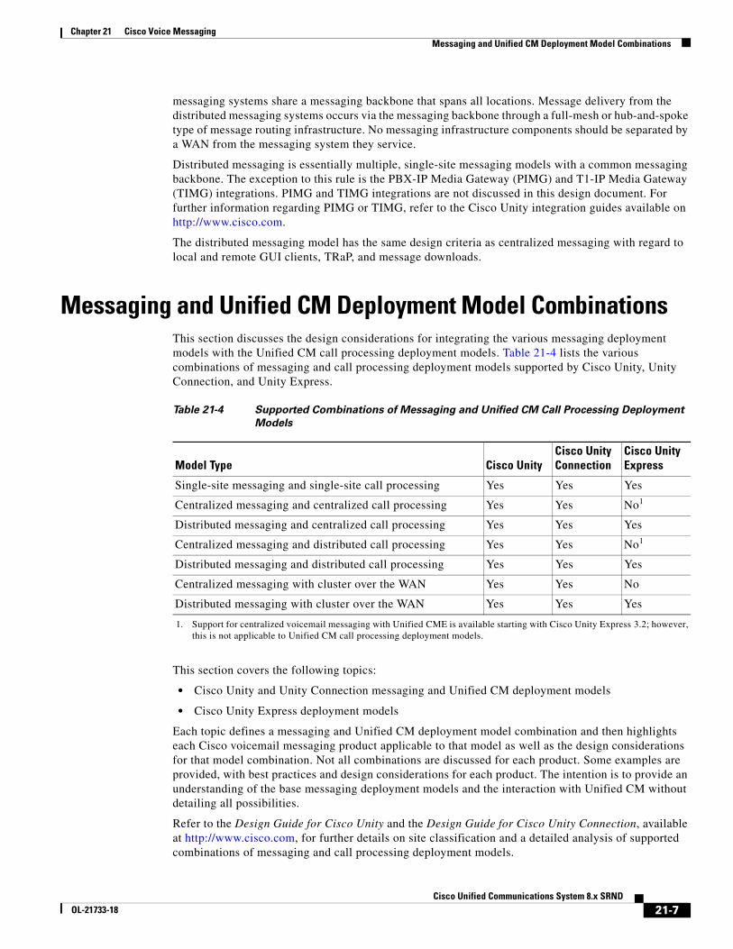
Messaging and Unified CM Deployment Model CombinationsThis section discusses the design considerations for integrating the various messaging deployment models with the Unified CM call processing deployment models. Table 21-4 lists the various combinations of messaging and call processing deployment models supported by Cisco Unity, Unity Connection, and Unity Express.
This section covers the following topics:
• Cisco Unity and Unity Connection messaging and Unified CM deployment models
• Cisco Unity Express deployment models
Each topic defines a messaging and Unified CM deployment model combination and then highlights each Cisco voicemail messaging product applicable to that model as well as the design considerations for that model combination. Not all combinations are discussed for each product. Some examples are provided, with best practices and design considerations for each product. The intention is to provide an understanding of the base messaging deployment models and the interaction with Unified CM without detailing all possibilities.
Refer to the Design Guide for Cisco Unity and the Design Guide for Cisco Unity Connection, available at http://www.cisco.com, for further details on site classification and a detailed analysis of supported combinations of messaging and call processing deployment models.
Table 21-4 Supported Combinations of Messaging and Unified CM Call Processing Deployment
Models
Model Type Cisco UnityCisco Unity Connection
Cisco Unity Express
Single-site messaging and single-site call processing Yes Yes Yes
Centralized messaging and centralized call processing Yes Yes No1
1. Support for centralized voicemail messaging with Unified CME is available starting with Cisco Unity Express 3.2; however, this is not applicable to Unified CM call processing deployment models.
Distributed messaging and centralized call processing Yes Yes Yes
Centralized messaging and distributed call processing Yes Yes No1
Distributed messaging and distributed call processing Yes Yes Yes
Centralized messaging with cluster over the WAN Yes Yes No
Distributed messaging with cluster over the WAN Yes Yes Yes
21-7Cisco Unified Communications System 8.x SRND
OL-21733-18

Chapter 21 Cisco Voice MessagingMessaging and Unified CM Deployment Model Combinations
Cisco Unity and Unity Connection Messaging and Unified CM Deployment Models
This section discusses some of the various combinations of messaging and call processing deployment models for Cisco Unity and Unity Connection.
Centralized Messaging and Centralized Call Processing
In centralized messaging, the voice messaging server is located in the same site as the Unified CM cluster. With centralized call processing, subscribers may be located either remotely and/or locally to the cluster and messaging server(s). (See Figure 21-1.) When remote users access resources at the central site (such as voice ports, IP phones, or PSTN gateways, as in Tail-End Hop-Off (TEHO)), these calls are transparent to gatekeeper call admission control. Therefore, regions and locations must be configured in Unified CM for call admission control. (See Managing Bandwidth, page 21-34.) When making inter-region calls to IP phones or MGCP gateways, IP phones automatically select the inter-region codec that has been configured. With Cisco Unity messaging deployments, native transcoding should be disabled so that the voice ports use Unified CM transcoding resources for calls that transverse the WAN (inter-region). See the section on Native Transcoding Operation, page 21-35, for information on disabling this feature in Cisco Unity.
Figure 21-1 Centralized Messaging with Centralized Call Processing
Region 1
RTP stream of Voice ports callsfrom Region 2 to Centralized Unity.
Region 2
Unified/IntegratedMessaging
Central Site
Remote Site
101
G.711 G.729
Switch
Transcoder
100PC
Unified/IntegratedMessaging
201 Switch 200PC
1533
78
M
M
M
M
M
IP IP
IP IP
V
IP WAN PSTN
Messaging SystemServers
UnityConnection
Unity
ORC
SRST or UnifiedCME as SRST
21-8Cisco Unified Communications System 8.x SRND
OL-21733-18

Chapter 21 Cisco Voice MessagingMessaging and Unified CM Deployment Model Combinations
In Figure 21-1, regions 1 and 2 are configured to use G.711 for intra-region calls and G.729 for inter-region calls. Native transcoding has been disabled on the Cisco Unity server.
As Figure 21-1 shows, when a call is made from extension 200 to the voicemail ports in Region 1, the inter-region G.729 codec is used at the endpoint but the RTP stream is transcoded to use G.711 on the voice ports. Native transcoding on the Cisco Unity server has been disabled in this example. Unified CM transcoding resources must be located at the same site as the voicemail system.
Impact of Non-Delivery of RDNIS on Voicemail Calls Routed by AAR
In centralized messaging environments, automated alternate routing (AAR), a Unified CM feature, can route calls over the PSTN to the messaging store at the central site when the WAN is oversubscribed. However, when calls are rerouted over the PSTN, Redirected Dialed Number Information Service (RDNIS) can be affected. Incorrect RDNIS information can impact voicemail calls that are rerouted over the PSTN by AAR when Cisco Unity or Unity Connection is remote from its messaging clients. If the RDNIS information is not correct, the call will not reach the voicemail box of the dialed user but will instead receive the auto-attendant prompt, and the caller might be asked to re-enter the extension number of the party they wish to reach. This behavior is primarily an issue when the telephone carrier is unable to ensure RDNIS across the network. There are numerous reasons why the carrier might not be able to ensure that RDNIS is properly sent. Check with your carrier to determine if they provide guaranteed RDNIS deliver end-to-end for your circuits. The alternative to using AAR for oversubscribed WANs is simply to let callers hear reorder tone in an oversubscribed condition.
Survivable Remote Site Voicemail
Survivable Remote Site Voicemail (SRSV) provides backup voicemail service in the centralized messaging and centralized call processing deployment. SRSV utilizes Cisco Unity Express in the branch location to provide backup voicemail service for Cisco Unity Connection located in the headquarters when the connection between sites is unavailable. (See Figure 21-2.) During normal operation, Cisco Unified Messaging Gateway in the headquarters retrieves the configurations (for example, SRST phones, user, and mailbox information) from Cisco Unified CM and Cisco Unity Connection to provision and update the mailboxes in Cisco Unity Express SRSV based on a configured schedule. Cisco Unity Express SRSV is active when only SRST is activated, and it remains idle otherwise. When the network connection between sites is restored, Cisco Unity Express SRSV uploads all messages (new, saved, deleted, and so forth) to Cisco Unity Connection.
21-9Cisco Unified Communications System 8.x SRND
OL-21733-18

Chapter 21 Cisco Voice MessagingMessaging and Unified CM Deployment Model Combinations
Figure 21-2 Typical Survivable Remote Site Voicemail Deployment
Note Survivable Remote Site Telephony (SRST) and Cisco Unity Express SRSV are one logical unit, with Cisco Unity Express SRSV installed in the SRST router.
Note The Cisco Unified Messaging Gateway SRSV feature has reached End-of-Sale (EoS) and End-of-Life (EoL). There is no replacement available for the SRSV feature at this time. For more information on this, refer to the End-of-Sale and End-of-Life Announcement at http://www.cisco.com/en/US/prod/collateral/voicesw/ps6789/ps5745/ps8605/end_of_life_notice_c51-695653.pdf.
SRSV uses bandwidth from the WAN link during the following activities:
• Configuration uploads from Unified CM and Cisco Unity Connection to Cisco Unity Express SRSV
• Voice message uploads from Cisco Unity Express SRSV to Cisco Unity Connection when the WAN link is restored
To minimize the impact of SRSV traffic on the existing voice network, classify the SRSV traffic (configuration and voice message uploads) as best-effort. The SRSV software does not mark any network packets. Cisco recommends marking the SRSV traffic with IP Precedence 0 (DSCP 0 or PHB BE) in the network edge router in order to yield to voice and other high-priority traffic. To further reduce the impact, Cisco recommends scheduling the configuration uploads to take place during non-peak hours (for example, in the evening hours or during the weekend). The schedule can be configured from the Unified Messaging Gateway SRSV web interface.
When you deploy SRSV, the following rules apply:
• Unified Messaging Gateway SRSV supports up to 1,000 Cisco Unity Express SRSV nodes.
• SRSV does not support Cisco Unified CM Business Edition.
• Install Cisco Unity Express SRSV on the SRST router or on Unified CME running in SRST mode.
2538
68
PSTN
WANCisco UnifiedMessagingGatewaySRSV
V
IP IPIP Cisco UnityExpress SRSV
SRST
IP IPIP
Cisco UnityConnection
Cisco UnifiedCM Cluster
HeadquartersBranch
21-10Cisco Unified Communications System 8.x SRND
OL-21733-18

Chapter 21 Cisco Voice MessagingMessaging and Unified CM Deployment Model Combinations
• Multiple SRST routers are supported in the branch, but each router must have its own Cisco Unity Express SRSV and allows only one Cisco Unity Express SRSV.
• Deploy redundant Unified Messaging Gateway SRSV to provide high availability for voice message uploads. Unified Messaging Gateway SRSV does not support high availability for configuration uploads.
• Use Secure Socket Layer (SSL) protocol to secure the connection between Unified Messaging Gateway SRSV and Cisco Unity Express SRSV.
• SRSV does not support Cisco Unity.
For more information on SRSV, refer to the documentation available at http://www.cisco.com/go/srsv.
Distributed Messaging with Centralized Call Processing
Distributed messaging means that there are multiple messaging systems distributed within the telephony environment, and each messaging system services only local messaging clients. This model differs from centralized messaging, where clients are both local and remote from the messaging system.
Figure 21-3 illustrates the distributed messaging model with centralized call processing. As with other multisite call processing models, the use of regions and locations is required to manage WAN bandwidth. For this model, you should also disable native transcoding in Cisco Unity.
Note that Cisco Unified Communications Manager Express (Unified CME) in SRST mode is used for call processing backup of both IP phones and Cisco Unity or Unity Connection voicemail ports. Deployed at the remote site (for example, Region 2 in Figure 21-3), this fallback support provides backup call processing in the event that the phones lose connectivity with Unified CM, such as during a WAN failure, while simultaneously providing users at the remote site with access to the local Cisco Unity or Unity Connection server as well as MWI support during WAN failure. For further details on Unified CME in SRST mode, refer to the Unified CME product documentation on http://www.cisco.com.
21-11Cisco Unified Communications System 8.x SRND
OL-21733-18

Chapter 21 Cisco Voice MessagingMessaging and Unified CM Deployment Model Combinations
Figure 21-3 Distributed Messaging with Centralized Call Processing
For the configuration in Figure 21-3, transcoder resources must be local to each Cisco Unity message system site. Regions 1 and 2 are configured to use G.711 for intra-region calls and G.729 for inter-region calls. Native transcoding has been disabled on the Cisco Unity servers.
Voice messaging ports for both Cisco Unity or Unity Connection servers must be assigned the appropriate region and location by means of calling search spaces and device pools configured on the Unified CM server. In addition, to associate telephony users with a specific group of voicemail ports, you must configure Unified CM voicemail profiles. For details on configuring calling search spaces, device pools, and voicemail profiles, refer to the applicable version of the Cisco Unified Communications Manager Administration Guide, available at http://www.cisco.com.
The messaging systems are "networked" together to present a single messaging system to both inside and outside users. For information about Cisco Unity Networking for the distributed Unity servers, refer to the Networking in Cisco Unity Guide, available at
http://www.cisco.com/en/US/products/sw/voicesw/ps2237/products_feature_guides_list.html
Cisco Unity Connection supports digital networking, allowing multiple Cisco Unity Connection systems to be networked together. Up to 10 nodes (single or active/active pair) can be connected together in a digital network system. Additionally, if required, two digital networks can be joined to support a
MessagingSystemServers
Unity1
Unity2
Region 1
Region 2CiscoUnity
Express,SRST, or
UnifiedCME as
SRST
UnifiedMessaging
CentralSite
RemoteSite2
101 Switch
Transcoder
Transcoder
100PC
UnifiedMessaging
201 Switch 200PC
2715
46
M
M
M
M
M
IP IP
IP IP
V
IP WAN PSTN
21-12Cisco Unified Communications System 8.x SRND
OL-21733-18

Chapter 21 Cisco Voice MessagingMessaging and Unified CM Deployment Model Combinations
maximum of 20 nodes. This provides support for up to 100,000 entities in the directory. Cisco Unity Connection can integrate with a corporate directory such as Microsoft Active Directory to synchronize users and use digital networking simultaneously. In this configuration, each Cisco Unity Connection server or server pair will be able to synchronize up to 20,000 users from the corporate directory. Refer to the Design Guide for Cisco Unity Connection, available at http://www.cisco.com, for further information regarding digital networking or directory integration in Cisco Unity Connection.
Cisco Unity and Unity Connection with Unified CME in SRST Mode
Unified CME in SRST mode offers the possibility for both Cisco Unity and Unity Connection servers located in remote sites and registered with a Unified CM at the central site to fall-back to Unified CME in the remote location. When the WAN link is down and the phones fail-over to Unified CME in SRST mode, Cisco Unity and Unity Connection voicemail ports can also fail-over to Unified CME in SRST mode to provide the remote site users with access to their voicemail with MWI during the WAN outage.
This scenario requires the following:
• Cisco Unified CME 4.0 or later
• Cisco Unity 4.0(5) or later with TSP version 8.1(3) or later
• Cisco Unity Connection 2.x or later
Note MWI has to be resynchronized from the Cisco Unity or Unity Connection server whenever a failover happens from Unified CM to Unified CME in SRST mode, or vice versa.
21-13Cisco Unified Communications System 8.x SRND
OL-21733-18

Chapter 21 Cisco Voice MessagingMessaging and Unified CM Deployment Model Combinations
Combined Messaging Deployment Models
It is possible to combine messaging models in the same deployment, provided that the deployment adheres to all the guidelines listed in the preceding sections. Figure 21-4 shows a user environment in which both centralized and distributed messaging are employed simultaneously.
Figure 21-4 Combined Deployment Models
Figure 21-4 shows the combination of two messaging models. Regions 1 and 3 use centralized messaging with centralized call processing, while Region 2 uses distributed messaging with centralized call processing. All regions are configured to use G.711 for intra-region calls and G.729 for inter-region calls.
In Figure 21-4, centralized messaging and centralized call signaling are used between the Central Site and Site3. The messaging system at the Central Site provides messaging services for clients at both the Central Site and Site3. Site2 uses the distributed messaging model with centralized call processing. The messaging system (Unity2) located at Site2 provides messaging services for only those users located within Site2. In this deployment, both models adhere to their respective design guidelines as presented
MessagingSystemServers
Unity1
Unity2
Region 1
Region 2
UnifiedMessaging
CentralSite
RemoteSite2
RemoteSite3
Region 3
101 Switch
Transcoder
Transcoder
100PC
UnifiedMessaging
UnifiedMessaging
201 Switch 200PC
2715
47
M
M
M
M
M
IP IP
IP IP
301
Switch
IP
300 IP
PC
V
IP WAN PSTN
Cisco UnityExpress, SRST,or Unified CMEas SRST
Cisco UnityExpress, SRST, orUnified CME asSRST
21-14Cisco Unified Communications System 8.x SRND
OL-21733-18

Chapter 21 Cisco Voice MessagingMessaging and Unified CM Deployment Model Combinations
in this chapter. Transcoding resources are located locally to each messaging system site, and they support clients who access messaging services from a remote site (relative to the messaging system), as in the case of a Site2 user leaving a message for a Central Site user.
In addition, Cisco Unified Communications Manager Express (Unified CME) in SRST mode is used for call processing backup of both IP phones and Cisco Unity or Unity Connection voicemail ports. Deployed at the remote site (for example, Region 2 in Figure 21-4), this fallback support provides backup call processing in the event that the phones lose connectivity with Unified CM, such as during a WAN failure, while simultaneously providing users at the remote site with access to the local Cisco Unity or Unity Connection server as well as MWI support during WAN failure. For further details on Unified CME in SRST mode, refer to the product documentation on http://www.cisco.com.
Centralized Messaging with Clustering Over the WAN
This section addresses Cisco Unity design issues for deploying centralized messaging with Unified CM clustering over the WAN with local failover. In the case of a WAN failure with this model, all remote messaging sites will lose voicemail capability until the WAN is restored. (See Figure 21-5.)
Clustering over the WAN supports local failover. With local failover, each site has a backup subscriber server physically located at the site. This section focuses on deploying Cisco Unity centralized messaging with local failover for clustering over the WAN.
For additional information, refer to the section on Clustering Over the IP WAN, page 5-45.
21-15Cisco Unified Communications System 8.x SRND
OL-21733-18

Chapter 21 Cisco Voice MessagingMessaging and Unified CM Deployment Model Combinations
Figure 21-5 Cisco Unity Centralized Messaging and Clustering Over the WAN with Local Failover
For minimum bandwidth requirements between clustered servers see the section on Local Failover Deployment Model, page 5-49.
Clustering over the WAN with Unified CM supports up to eight sites, as does Cisco Unity. The voicemail ports are configured only at the site where the Cisco Unity messaging system is located (see Figure 21-5). Voicemail ports do not register over the WAN to the remote site(s). Messaging clients at the other site(s) access all voicemail resources from the primary site. There is no benefit to configuring voice ports over the WAN to any of the remote sites because, in the event of a WAN failure, remote sites would lose access to the centralized messaging system. Because of bandwidth consideration, the voicemail ports should have TRaP disabled and all messaging clients should download voicemail messages to their local PCs (unified messaging only).
IP WAN PSTN
Region 1Location 1
Region 2Location 2
Unified/IntegratedMessaging
Site 1
Site 2
101 Switch
Transcoder
100PC
Unified/IntegratedMessaging
201 Switch 200PC
IP IP
IP IP
V
Sub1 BKUP1
Publisher/TFTP
M
M
M
Sub2 BKUP2
M M
1533
79
Primaryvoice ports
Secondaryvoice ports
Messaging SystemServers
UnityConnection
Unity
ORC
21-16Cisco Unified Communications System 8.x SRND
OL-21733-18

Chapter 21 Cisco Voice MessagingMessaging and Unified CM Deployment Model Combinations
Distributed Messaging with Clustering Over the WAN
Local failover sites that also have Cisco Unity messaging server(s) deployed would have voice ports registered to the local Unified CM subscriber server(s), similar to the centralized messaging model. For information about configuring the voice ports, see Voice Port Integration with a Unified CM Cluster, page 21-41, and Voice Port Integration with Dedicated Unified CM Backup Servers, page 21-43.
Figure 21-6 Cisco Unity Distributed Messaging and Clustering over the WAN with Local Failover
In a purely distributed messaging implementation with clustering over the WAN, each site in the cluster would have its own Cisco Unity messaging server with messaging infrastructure components. If not all of the sites have local Cisco Unity messaging systems but some sites have local messaging clients using a remote messaging server(s), this deployment would be a combination model with both distributed messaging and centralized messaging. (See Combined Messaging Deployment Models, page 21-14.) In the event of a WAN failure in this model, all remote sites that use centralized messaging will lose voicemail capability until the WAN is restored.
IP WAN PSTN
Region 1Location 1
Region 2Location 2
UnifiedMessaging
Site 1
Site 2
101 Switch
Transcoder
Transcoder
100PC
UnifiedMessaging
201 Switch 200PC
IP IP
IP IP
V
MessagingSystemServers
Unity
MessagingSystemServers
Unity
Sub1 BKUP1
Publisher/TFTP
M
M
M
Sub2 BKUP2
M M92
381
Primaryvoice ports
Secondaryvoice ports
21-17Cisco Unified Communications System 8.x SRND
OL-21733-18

Chapter 21 Cisco Voice MessagingMessaging and Unified CM Deployment Model Combinations
Each site that does not have a local messaging server must use a single messaging server for all of its messaging clients, but all such sites do not have to use the same messaging server. For example, suppose Site1 and Site2 each have a local messaging server. Site3 can then have all of its clients use (register with) the messaging server at Site2, while Site4 can have all of its clients use the messaging server at Site1. Transcoder resources are required at sites that have local Cisco Unity messaging server(s).
As with other distributed call processing deployments, calls going between these sites are transparent to gatekeeper call admission control, therefore you must configure regions and locations in Unified CM to provide call admission control. (See Managing Bandwidth, page 21-34.)
The distributed Cisco Unity servers may also be networked digitally. For more information on this topic, refer to the Cisco Unity Networking Guide, available at http://www.cisco.com. The networking guides are specific to the particular messaging store deployed.
Messaging RedundancyMessaging redundancy is discussed in this section as it refers to Cisco Unity and Cisco Unity Connection. Cisco Unity Express does not support messaging redundancy.
Cisco Unity
Cisco Unity supports two categories of redundancy. The first one is referred to simply as Unity Failover (local messaging failover), and it provides system malfunction failover. The second category is referred to as Standby Redundancy, and it provides disaster-recovery across geographic locations. See the Cisco Unity Design Guide for a comparison of Cisco Unity Failover and Standby Redundancy.
Cisco Unity failover consists of two servers, a primary and a secondary, configured as an active/passive redundant pair of servers, where the primary server is active and taking calls while the secondary is inactive and not taking calls. Any changes to subscriber or configuration data on the primary server are automatically replicated to the secondary server. If the primary server stops functioning for some reason, the secondary server automatically becomes the active server and starts taking calls while the primary server temporarily becomes inactive.
You can implement local messaging failover as illustrated in Figure 21-7. With local failover, both the primary and secondary Cisco Unity servers are located at the same site on the same highly available LAN.
Figure 21-7 Local Failover of Cisco Unity Messaging
2715
72
UnityPrimaryActive
Switch
UnitySecondary
Passive
21-18Cisco Unified Communications System 8.x SRND
OL-21733-18

Chapter 21 Cisco Voice MessagingMessaging and Unified CM Deployment Model Combinations
Cisco Unity Standby Redundancy also provides disaster recovery across geographic locations. There are still two servers, a primary and a secondary, but they are installed in separate data centers, commonly in separate cities. If the data center in which the primary server is installed is affected by a natural disaster or other catastrophe, someone in (or with remote access to) the disaster-recovery facility manually activates the secondary server, and the secondary server begins taking calls. For further information on the requirements for Standby Redundancy or Failover (local messaging failover), refer to the appropriate version of the System Requirements for Cisco Unity, available on http://www.cisco.com.
Cisco Unity Connection
Cisco Unity Connection supports messaging redundancy and load balancing in an active-active redundancy model consisting of two servers, a primary and a secondary, configured as an active/active redundant pair of servers, where both the primary and secondary servers actively accept calls as well as HTTP and IMAP requests. For more information, refer to the Design Guide for Cisco Unity Connection, available at http://www.cisco.com.
Figure 21-8 illustrates Cisco Unity Connection active/active messaging redundancy.
Figure 21-8 Redundancy of Cisco Unity Connection Messaging
Both Cisco Unity and Cisco Unity Connection SIP trunk implementation requires call forking for messaging redundancy functionality. Currently, Unified CM does not support call forking on SIP trunks; therefore, Cisco Unity failover is not available when SIP trunks are used with Unified CM. However, when using SIP trunks with a Cisco Unity Connection server pair in active/active redundancy, Cisco recommends that you configure two separate SIP trunks, one to each server in the server pair, and add them to the same route group associated to the same route list. The route group should be configured in top-down order so that calls are sent first to the primary Unity Connection server and then overflow to the secondary Unity Connection server.
Cisco Unity Failover and Clustering Over the WAN
When deploying Cisco Unity local failover with clustering over the WAN, apply the same design practices described in Centralized Messaging with Clustering Over the WAN, page 21-15, and Distributed Messaging with Clustering Over the WAN, page 21-17. The voice ports from the primary Cisco Unity server should not cross the WAN during normal operation.
Figure 21-9 depicts Cisco Unity local failover. Note that the primary and secondary Cisco Unity servers are both physically located at the same site. Cisco Unity failover supports up to the maximum number of remote sites available with clustering over the WAN for Unified CM.
2715
73
UnityConnection
Active
Switch
UnityConnection
Active
21-19Cisco Unified Communications System 8.x SRND
OL-21733-18

Chapter 21 Cisco Voice MessagingMessaging and Unified CM Deployment Model Combinations
Figure 21-9 Cisco Unity Local Failover and Clustering Over the WAN
For information on configuring Cisco Unity failover, refer to the Cisco Unity Failover Configuration and Administration Guide, available at http://www.cisco.com.
Cisco Unity Failover Deployed Over a Split Data Center
As mentioned earlier, Cisco Unity failover can be configured to operate for high availability over a WAN; however, there are a number of requirements for deploying this. For example, if full redundancy at geographically separated data centers is important, there are certain requirements that must be met in order to ensure the successful operation of an installation in this configuration. Figure 21-10 depicts Cisco Unity failover for geographically separated data centers.
IP WAN PSTN
Region 1Location 1
Region 2Location 2
UnifiedMessaging
Site 1
Site 2
101 Switch
Transcoder
100PC
UnifiedMessaging
201 Switch 200PC
IP IP
IP IP
V
Cisco UnityLocal Failover
Primary Secondary
Sub1 BKUP1
Publisher/TFTP
M
M
M
Sub2 BKUP2
M M
9238
2
Primaryvoice ports
Secondaryvoice ports
21-20Cisco Unified Communications System 8.x SRND
OL-21733-18

Chapter 21 Cisco Voice MessagingMessaging and Unified CM Deployment Model Combinations
Figure 21-10 Cisco Unity Failover for Geographically Separated Data Centers
The following requirements apply to the configuration shown in Figure 21-10:
• Maximum of 10 ms round trip time (RTT) between primary and secondary Cisco Unity servers
• Minimum of 1 Gigabit of bandwidth
• Maximum of 10 ms RTT between the Cisco Unity sever and respective messaging server
• The Cisco Unity server and domain controller or global catalog server should be co-located
For a complete set of requirements, refer to the latest version of the System Requirements for Cisco Unity, available at
http://www.cisco.com/en/US/products/sw/voicesw/ps2237/prod_installation_guides_list.html
Data Center 1 Data Center 2
MicrosoftActive
Directory
ClusteredMessage Store
ClusteredMessage Store
MicrosoftActive
Directory
2538
69
V
Branch A Branch B
V
IP IPIPMPLS/MAN
V V
IP IPIP IP IPIP
> Gigabit (< 10 ms RTT)
Cisco UnityPrimary
Unified CMCluster
Cisco Unity SecondaryUnified CM
Cluster
IP IPIP
21-21Cisco Unified Communications System 8.x SRND
OL-21733-18

Chapter 21 Cisco Voice MessagingMessaging and Unified CM Deployment Model Combinations
Cisco Unity Connection Redundancy and Clustering Over the WAN
Cisco Unity Connection supports active/active clustering for redundancy and can be deployed over the WAN. The active/active or "high availability" configuration provides both high availability and redundancy. Both servers in the active/active pair run the Cisco Unity Connection application to accept calls as well as HTTP and IMAP requests from clients. Each of the servers from the cluster can be deployed over the WAN at different sites following required design consideration. Figure 21-11 depicts a Cisco Unity Connection active/active deployment for geographically separated data centers
Figure 21-11 Cisco Unity Connection with High Availability Between Two Sites
The following requirements apply to deployments of Cisco Unity Connection servers over different sites:
• Maximum of 150 ms RTT between an active/active pair at different sites.
• Minimum of 7 Mbps bandwidth is required for every 50 ports. (For example, 250 ports require 35 Mbps.)
Note Bandwidth and latency requirements may differ for different versions of Cisco Unity Connection.
Cisco Unity Connection
PrimaryUnified CM
Cluster
Data Center 1 Data Center 2
MicrosoftActive
Directory
Email Message Store(if applicable)
Email Message Store(if applicable)
Cisco UnityConnection Secondary
Unified CMCluster
IP IPIP
MicrosoftActive
Directory
2538
70
V
Branch A Branch B
V
IP IPIPMPLS/MAN
V V
IP IPIP IP IPIP
7 Mbps per 50 ports
(150 ms RTT)
21-22Cisco Unified Communications System 8.x SRND
OL-21733-18

Chapter 21 Cisco Voice MessagingMessaging and Unified CM Deployment Model Combinations
For a complete set of requirements, refer to the latest version of the System Requirements for Cisco Unity Connection, available at
http://www.cisco.com/en/US/products/ps6509/prod_installation_guides_list.html
Note The Cisco Unity Connection cluster feature is not supported for use with Cisco Business Edition 3000 and 5000.
Centralized Messaging with Distributed Unified CM Clusters
Cisco Unity and Unity Connection can also be deployed in a centralized messaging configuration with multiple Unified CM clusters (see Figure 21-12). See the section on Telephony Integrations, page 21-38, for details on multiple integrations and MWI considerations with multiple Unified CM clusters.
Figure 21-12 Integrating Cisco Unity or Unity Connection with Multiple Unified CM Clusters
For the configuration in Figure 21-12, messaging clients at both Cluster 1 and Cluster 2 sites use the Cisco Unity or Unity Connection messaging infrastructure physically located at Cluster 1.
1531
58
IP WAN/PSTN
V
Primary Voicemail PortsSecondary Voicemail Ports
Xcode
Xcode
Unified CM Cluster
M
M
M M
M
V
Unified CM Cluster
M
M
M M
M
Messaging SystemServers
UnityConnection
Unity
ORC
21-23Cisco Unified Communications System 8.x SRND
OL-21733-18

Chapter 21 Cisco Voice MessagingMessaging and Unified CM Deployment Model Combinations
Cisco Unity Express Deployment ModelsThis section begins with a quick overview of Cisco Unity Express, covering product related information. Next the deployment models section presents three supported deployment models with Cisco Unity Express, focusing on distributed voice messaging with both centralized and distributed call processing followed by some deployment characteristics and design guidelines. Lastly, this section discusses the signaling call flows and the various protocols used between Cisco Unity Express and Unified CM as well as between Cisco Unity Express and Unified SRST or Unified CME in SRST mode.
Overview of Cisco Unity Express
Cisco Unity Express is Linux-based software running on a Cisco Network Module in Cisco Integrated Services Routers (ISRs). It is an entry-level auto-attendant (AA) and voicemail solution that can be deployed with Cisco Unified Communications Manager (Unified CM), Cisco Unified SRST, or Cisco Unified Communications Manager Express (Unified CME). In prior releases, Cisco Unity Express was limited to a co-resident deployment with Unified CME or a Survivable Remote Site Telephony (SRST) router. However, with the H.323-to-SIP call routing capability introduced in Cisco IOS Release 12.3(11)T, Cisco Unity Express and SRST or Unified CME can reside on two separate routers when deployed with Unified CM or Unified CME, respectively. Cisco Unity Express uses SIP to communicate with Cisco Unified Communications Manager Express (Unified CME) while Cisco Unity Express uses JTAPI to connect to Cisco Unified Communications Manager (Unified CM).
For more information on supported hardware platforms and capacity with Cisco Unity Express, refer to the product release note available at http://www.cisco.com/en/US/products/sw/voicesw/ps5520/prod_release_notes_list.html.
For details on interoperability of Unified CM and Unified CME, see Interoperability of Unified CM and Unified CM Express, page 8-44.
For additional information on supported deployment models with Unified CME, refer to the appropriate Cisco Unified Communications Manager Express design documentation available at http://www.cisco.com.
Deployment Models
Cisco Unity Express can be deployed as a single site or distributed voicemail and automated attendant (AA) solution for Cisco Unified Communications Manager (Unified CM) or Unified Communications Manager Express (Unified CME). However, Cisco Unity Express is supported with all of the Cisco Unified CM deployment models, including:
• Single-site deployments
• Multisite deployments with centralized call processing
• Multisite deployments with distributed call processing
Figure 21-13 shows a centralized call processing deployment incorporating Cisco Unity Express, and Figure 21-14 shows a distributed call processing deployment.
Cisco Unity Express sites controlled by Unified CME, as well as other sites controlled by Unified CM, can be interconnected with each other using H.323 or SIP trunking protocol. Although Cisco Unity Express can integrate with either Unified CM or Unified CME, it cannot integrate with both simultaneously.
Note Cisco Unity Express supports a centralized deployment model with up to 10 Unified CMEs.
21-24Cisco Unified Communications System 8.x SRND
OL-21733-18

Chapter 21 Cisco Voice MessagingMessaging and Unified CM Deployment Model Combinations
Figure 21-13 Cisco Unity Express in a Centralized Call Processing Deployment
1147
07
V
IP IPIP
CiscoUnified CM
IP IPIP
Cisco Unity Express, SRST, or Unified CME as SRST
CentralizedUnity server
VoIPWAN
PSTN
M
M
M M
M
IP IPIP
Cisco Unity Express, SRST, or Unified CME as SRST
V
21-25Cisco Unified Communications System 8.x SRND
OL-21733-18

Chapter 21 Cisco Voice MessagingMessaging and Unified CM Deployment Model Combinations
Figure 21-14 Cisco Unity Express in a Distributed Call Processing Deployment
The most likely deployment model to use Cisco Unity Express is the multisite WAN model with centralized call processing, where Cisco Unity Express provides distributed voicemail at the smaller remote offices and a central Cisco Unity system provides voicemail to the main campus and larger remote sites.
Use Cisco Unity Express as a distributed voicemail solution if any of the following conditions apply to your Unified CM network deployment:
• Survivability of voicemail and AA access must be ensured regardless of WAN availability.
• Available WAN bandwidth is insufficient to support voicemail calls traversing the WAN to a central voicemail server.
• There is limited geographic coverage of the AA or branch site PSTN phone numbers published to the local community, and these numbers cannot be dialed to reach a central AA server without incurring toll charges.
• The likelihood is high that a PSTN call into a branch office will be transferred from the branch AA to a local extension in the same office.
• Management philosophy allows remote locations to select their own voicemail and AA technology.
The following characteristics and guidelines apply to Cisco Unity Express in either a centralized or distributed Unified CM deployment:
• A single Cisco Unity Express can be integrated with a single Unified CM cluster.
• Cisco Unity Express integrates with Unified CM using a JTAPI application and Computer Telephony Integration (CTI) Quick Buffer Encoding (QBE) protocol. CTI ports and CTI route points control the Cisco Unity Express voicemail and automated attendant (AA) applications.
1147
08
V
IP IPIP
CiscoUnified CM
IP IPIP
Cisco Unity Express, Unified CME
CentralizedUnity server
VoIPWAN
PSTN
M
M
M M
M
IP IPIP
Cisco Unity Express, SRST, or Unified CME as SRST
V
V
IP IPIP
CiscoUnified CM
CentralizedUnity server
M
M
M M
M
V
21-26Cisco Unified Communications System 8.x SRND
OL-21733-18

Chapter 21 Cisco Voice MessagingMessaging and Unified CM Deployment Model Combinations
• Cisco Unity Express provides voicemail functionality to Cisco Unified IP Phones running Skinny Client Control Protocol (SCCP). Cisco Unity Express 2.3 and later releases also provide support for Session Initiation Protocol (SIP) IP phones with Unified CM.
• The following CTI route points are defined on Unified CM for Cisco Unity Express:
– Automated attendant entry point (Cisco Unity Express can contain up to five distinct AAs and may therefore require up to five different route points.)
– Voicemail pilot number
– Greeting management system (GMS) pilot number (Optional; if the GMS is not used, then this route point need not be defined.)
• The number of CTI ports and mailboxes supported for Cisco Unity Express on Unified CM depends on the hardware platform. For details, refer to the Cisco Unity Express data sheet available at:
http://www.cisco.com/en/US/products/sw/voicesw/ps5520/products_data_sheets_list.html
• For Cisco Unity Express deployments that require more than the maximum number of supported mailboxes, consider using Cisco Unity or other voicemail solutions.
• Each Cisco Unity Express mailbox can be associated with a maximum of two different extensions, if needed.
• The automated attendant function for any office deployed with Cisco Unity Express can be local to the office (using the AA application in Cisco Unity Express) or centralized (using Cisco Unity Express for voicemail only).
• Cisco Unity Express can be networked with other Cisco Unity Expresses or with Cisco Unity via Voice Profile for Internet Mail (VPIM) version 2. Thus, a Cisco Unity Express subscriber can send, receive, or forward messages to or from another remote Cisco Unity Express or Cisco Unity subscriber.
• Cisco Unity Express allows you to specify up to three Unified CMs for failover. If IP connectivity to all three Unified CMs is lost, Cisco Unity Express switches to Survivable Remote Site Telephony (SRST) call signaling, thus providing AA call answering service as well as mailbox access to IP phones and PSTN calls coming into the branch office.
• Cisco Unity Express automated attendant supports dial-by-extension and dial-by-name functions. The dial-by-extension operation enables a caller to transfer a call to any user endpoint in the network. The dial-by-name operation uses the directory database internal to Cisco Unity Express and does not interact with external LDAP or Active Directory databases.
• Centralized Cisco Unity Express with Unified CM is not supported.
• Cisco Unity Express is not supported in pure SIP networks that do not have either Cisco Unified CM or Unified CME controlling the SIP phones.
• Cisco Unity Express can be deployed on a separate Unified CME or SRST router or a separate PSTN gateway.
• When Cisco Unity Express is deployed on a router separate from Unified CME or SRST, configure the command allow-connections h323 to sip for H.323-to-SIP routing.
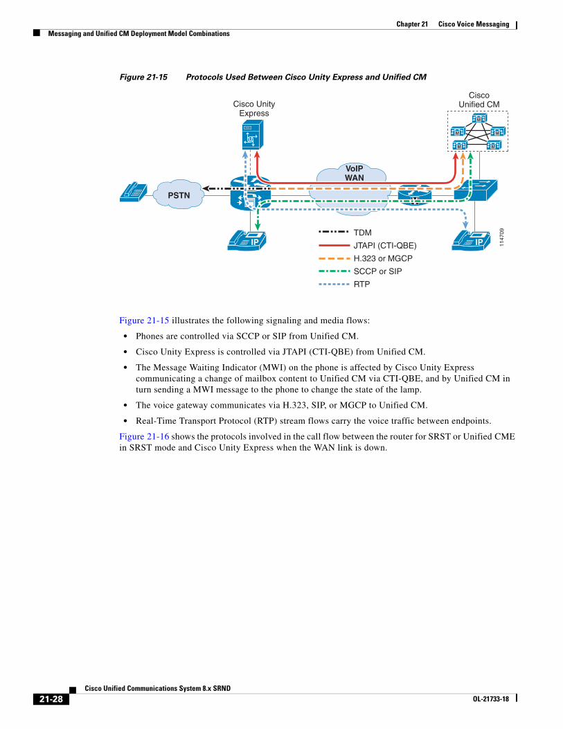
Figure 21-15 shows the protocols involved in the call flow between Unified CM and Cisco Unity Express.
21-27Cisco Unified Communications System 8.x SRND
OL-21733-18
Chapter 21 Cisco Voice MessagingMessaging and Unified CM Deployment Model Combinations
Figure 21-15 Protocols Used Between Cisco Unity Express and Unified CM
Figure 21-15 illustrates the following signaling and media flows:
• Phones are controlled via SCCP or SIP from Unified CM.
• Cisco Unity Express is controlled via JTAPI (CTI-QBE) from Unified CM.
• The Message Waiting Indicator (MWI) on the phone is affected by Cisco Unity Express communicating a change of mailbox content to Unified CM via CTI-QBE, and by Unified CM in turn sending a MWI message to the phone to change the state of the lamp.
• The voice gateway communicates via H.323, SIP, or MGCP to Unified CM.
• Real-Time Transport Protocol (RTP) stream flows carry the voice traffic between endpoints.
Figure 21-16 shows the protocols involved in the call flow between the router for SRST or Unified CME in SRST mode and Cisco Unity Express when the WAN link is down.
V
CiscoUnified CM
VoIPWAN
M
M
M M
M
Cisco UnityExpress
IP IP
PSTN
1147
09TDM
JTAPI (CTI-QBE)
H.323 or MGCP
SCCP or SIP
RTP
21-28Cisco Unified Communications System 8.x SRND
OL-21733-18

Chapter 21 Cisco Voice MessagingMessaging and Unified CM Deployment Model Combinations
Figure 21-16 Protocols Used Between Cisco Unity Express and the Router for SRST or Unified CME
in SRST Mode
Figure 21-16 illustrates the following signaling and media flows:
• Phones are controlled via SCCP or SIP from the router for SRST or Unified CME in SRST mode.
• Cisco Unity Express communicates with the SRST router via an internal SIP interface.
• Although MWI changes are not supported in SRST mode with previous releases of Cisco Unity Express, voice messages can be sent and retrieved as during normal operation, but the MWI lamp state on the phone remains unchanged until the phone registers again with Unified CM. At that time, all MWI lamp states are automatically resynchronized with the current state of the users' Cisco Unity Express voicemail boxes. Cisco Unity Express 3.0 and later releases support MWI for SRST mode.
• Cisco Unity Express supports SIP Subscriber/Notify and Unsolicited Notify to generate MWI notifications, in both Unified CME and SRST modes.
• RTP stream flows carry the voice traffic between endpoints.
• SRST subscribes to Cisco Unity Express for MWI for each of the ephone-dns registered to receive MWI notifications.
Note Unified CM MWI (JTAPI) is independent of the SIP MWI methods.
V
CiscoUnified CM
VoIPWAN
M
M
M M
M
Cisco UnityExpress
IPIP
PSTN
1147
10
SRST
TDM
SCCP or SIP
RTP
21-29Cisco Unified Communications System 8.x SRND
OL-21733-18

Chapter 21 Cisco Voice MessagingVoicemail Networking
Voicemail NetworkingThis section covers specific considerations for voicemail networking, including Cisco Unity, Cisco Unity Connection, and Cisco Unity Express. Also included is a high-level overview of voicemail networking with the Cisco Unified Messaging Gateway. For information specific to voicemail networking in Cisco Unity and Unity Connection, refer to the Design Guide for Cisco Unity or the Design Guide for Cisco Unity Connection, respectively, available at http://www.cisco.com.
Voicemail networking is the ability to allow subscribers (voicemail users) to send, receive, reply to, and forward voicemail messages between systems such as Cisco Unity, Cisco Unity Connection, and Cisco Unity Express using an embedded Simple Mail Transfer Protocol (SMTP) server and a subset of the Voice Profile for Internet Mail (VPIM) version 2 protocol. All three voicemail messaging products support interoperability between one another using VPIM messaging.
Cisco Unity Express Voicemail NetworkingCisco Unity Express communicates with Cisco Unity and Cisco Unity Connection by means of VPIM for message routing and SMTP for message delivery. Cisco Unity Express voicemail networking provides the following capabilities:
• Subscribers can receive, send, and forward messages to or from another remote Cisco Unity Express or Cisco Unity for locations configured on the originating system.
• Subscribers can also reply to a remote message received from a remote system.
• Subscribers can be recipients of a distribution list or individual message originating from Cisco Unity.
For more information on voicemail networking with a specific product, refer to the corresponding voicemail product documentation available at http://www.cisco.com.
Voicemail Networking with Cisco Unified Messaging GatewayThe Cisco Unified Messaging Gateway is Linux-based software running on a Cisco Network Module in Cisco Integrated Services Routers (ISRs). The Unified Messaging Gateway can act as the central hub for Cisco Unity, Cisco Unity Connection, and Cisco Unity Express to network VPIM v2 voicemail systems in a hub-and-spoke or hierarchical structure. This approach dramatically reduces the VPIM connections between voicemail systems and simplifies the configuration effort on each system. Each voicemail system (Cisco Unity, Cisco Unity Connection, Cisco Unity Express, or Avaya Interchange and Message Networking Server) needs to configure only the connection between itself and the Cisco Unified Messaging Gateway. The Unified Messaging Gateway then handles message routing and delivery between the systems. This end-to-end message networking functionality is required by medium to larger distributed enterprises in order to migrate to the Cisco Unified Communications solution.
The Cisco Unified Messaging Gateway provides the following benefits:
• It enables intelligent routing for multiple autonomous voicemail networks with VPIM.
• It provides scalable voicemail networks and interoperability with third-party voicemail systems (such as Avaya Interchange) over VPIM networks.
• It simplifies voicemail VPIM network additions and expansion.
Cisco Unified Messaging can support up to 1000 nodes and 50,000 subscribers. The number of subscribers is calculated based on 50 subscribers on any single Cisco Unity Express node that is registered with the Unified Messaging Gateway. The capacity of the Unified Messaging Gateway is tied
21-30Cisco Unified Communications System 8.x SRND
OL-21733-18

Chapter 21 Cisco Voice MessagingVoicemail Networking
to both the maximum number of nodes supported and the maximum number of subscribers supported, and increasing one quantity will cause a decrease in the other quantity. For example, if the network has Cisco Unity and/or Avaya endpoints with a large number of subscribers, the number of nodes that can register with the Unified Messaging Gateway will be significantly less.
Observe the following guidelines when deploying the Cisco Unified Messaging Gateway:
• Plan in advance for possible upgrades to the network if you anticipate the deployment will exceed the maximum capacity of one network module, because the network module with less capacity cannot be upgraded to the network module with higher capacity.
• Cisco Unity Express 3.1 and later releases register automatically and exchange directory information with the Cisco Unified Messaging Gateway, whereas Cisco Unity, Cisco Unity Connection, and Avaya Interchange or Message Networking Server must be provisioned manually on the Unified Messaging Gateway.
• Deploy a pair of Unified Messaging Gateways (primary and backup) for redundancy.
• Deploy up to 20 Unified Messaging Gateways (10 primary and 10 backup) for large deployments of up to 10,000 nodes.
Note Voicemail networking with the Cisco Unified Messaging Gateway does not apply to deployments of Cisco Unified Communications 500 Series for Small Businesses because the Cisco Unified Communications 500 Series supports a maximum of only 5 sites in a distributed environment.
Note The Cisco Unified Messaging Gateway VPIM feature has reached End-of-Sale (EoS) and End-of-Life (EoL). There is no replacement available for the VPIM feature at this time. For more information on this, refer to the End-of-Sale and End-of-Life Announcement at http://www.cisco.com/en/US/prod/collateral/voicesw/ps6789/ps5745/ps8605/end_of_life_notice_c51-695654.pdf.
For information on the Cisco Unified Communications 500 Series for Small Business deployments, refer to the product documentation on http://www.cisco.com.
For a complete discussion of VPIM as a distributed messaging solution and for design guidelines on the Cisco Unified Messaging Gateway, refer to the Cisco Unified Messaging Gateway product documentation available on http://www.cisco.com.
Voicemail InteroperabilityBoth Cisco Unity and Cisco Unity Connection offer good scalability options and interoperability support. Many deployments with Cisco Unity (standalone or cluster) can be expanded or migrated to include the following capabilities:
• Cisco Unity interoperability with Cisco Unity Connection
• Cisco Unity Connection interoperability with Cisco Unity Connection
For more information on these interoperability options, refer to the latest version of the Networking Guide for Cisco Unity Connection, available at
http://www.cisco.com/en/US/products/ps6509/prod_maintenance_guides_list.html
21-31Cisco Unified Communications System 8.x SRND
OL-21733-18

Chapter 21 Cisco Voice MessagingVoicemail Networking
The following guidelines apply to both types of interoperability mentioned above:
• A Cisco Unity Connection standalone server, cluster, or digital network can interoperate with a Cisco Unity server or digital network.
• One Cisco Unity Connection digital network can be joined to only one Cisco Unity or Unity Connection digital network.
• Maximum number of users and/or contacts can be 100,000 only in any interoperate system post that system will only allow to delete and change.
• Cisco Business Edition 3000 and 5000 are not supported.
• Designate one server each from the two Cisco Unity Connection and Cisco Unity digital networks as the bridgehead or site gateway.
• The Cisco Unity Connection server designated as the site gateway should be version 8.0 or higher.
• All Cisco Unity Connection servers digitally networked to Cisco Unity must be version 8.0 or higher.
• The Cisco Unity server designated as the site gateway should be version 8.0 or higher.
Cisco Unity and Cisco Unity Connection Interoperability
Cisco Unity and Cisco Unity Connection (digital networks) can join digitally to interoperate, thus enabling users to achieve directory sharing, easy administration, and other features. The following considerations apply to designing a Cisco Unity and Cisco Unity Connection network:
• All node of the Cisco Unity Connection network should be version 8.0 or higher.
• The Cisco Unity digital network can have servers other than the site gateway on version 5.0 or higher.
• Interoperability Gateway for Microsoft Exchange should be installed on a Microsoft Exchange server.
• The Microsoft Exchange server can be 2010, 2007, 2003, or Microsoft Business Productivity Online Services (BPOS) dedicated cloud solution (Exchange 2010 at the back end only for Cisco Unity Connection 8.6 and later releases). For further details on exact versions for Microsoft Exchange, refer to the Cisco Unity Connection design guides available at
http://www.cisco.com/en/US/products/ps6509/tsd_products_support_design.html
• There is no support for IBM Domino.
• The Cisco Unity Connection network can have a maximum of 10 nodes. In a Cisco Unity Connection cluster, only the publisher server is joined to the network, so a cluster counts as a single node toward the limit of 10 in each site.
21-32Cisco Unified Communications System 8.x SRND
OL-21733-18

Chapter 21 Cisco Voice MessagingVoicemail Networking
Cisco Unity Connection and Cisco Unity Connection Interoperability
Cisco Unity Connection (digital network, standalone servers, or cluster) can interoperate with another Cisco Unity Connection (digital network), thus enabling users to achieve directory sharing, easy administration, and other features, as well as expanding the total number of nodes (cluster or standalone server) up to 20. Consider the following points when deploying Cisco Unity Connection for interoperability with another Cisco Unity Connection network:
• If any of the Cisco Unity Connection nodes in the digital network system is running Cisco Unity Connection 7.0, then the maximum number of users supported is 50,000.
• There is no support for IBM Domino.
• Each Cisco Unity Connection digital network can support a maximum of 10 servers.
Cisco Unity and Unity Connection VirtualizationThe Cisco Unified Computing System (UCS) is a next-generation data center platform that unites computing, networking, storage access, and virtualization into a cohesive system designed to reduce total cost of ownership (TCO) and increase business agility. Cisco Unity and Cisco Unity Connection both support virtualization over VMware with the Cisco Unified Computing system.
The following key design considerations apply to Cisco Unity Connection virtualization:
• Supports up to 20,000 users
• The Tested Reference Configurations include selected Cisco Unified Computing System (UCS) platforms. Other platforms may be supported with the specifications-based hardware support policy.
• VMware ESXi is required for virtualization.
• Servers in an active/active cluster should be on separate blades, preferably on different chassis.
Note One CPU core per physical server must be left idle and reserved for the ESXi scheduler.
For more information on deploying Cisco Unified Communications, Cisco Unity, and Cisco Unity Connection in a virtualized system, refer to the documentation available at
http://www.cisco.com/go/uc-virtualized
General information about deploying Unified Communications on virtualized servers is also available in the section on Deploying Unified Communications on Virtualized Servers, page 5-58.
For Cisco Unity Connection virtualization, also refer to the latest version of the Design Guide for Cisco Unity Connection available at
http://www.cisco.com/en/US/products/ps6509/products_implementation_design_guides_list.html
For Cisco Unity virtualization, also refer to the latest version of the Design Guide for Cisco Unity Virtualization available at
http://www.cisco.com/en/US/products/sw/voicesw/ps2237/products_implementation_design_guides_list.html
21-33Cisco Unified Communications System 8.x SRND
OL-21733-18
Chapter 21 Cisco Voice MessagingBest Practices for Voice Messaging
Best Practices for Voice MessagingThis section discusses some general best practices and guidelines that were not mentioned previously yet are important aspects of the products and should be considered in the solution. They are separated into two groupings, Cisco Unity and Cisco Unity Connection in one grouping and Cisco Unity Express in another.
Best Practices for Deploying Cisco Unity and Cisco Unity Connection with Unified CM
This section applies to Cisco Unity and Unity Connection. For Cisco Unity Express, see Best Practices for Deploying Cisco Unity Express, page 21-45.
Managing Bandwidth
Unified CM provides a variety of features for managing bandwidth. Through the use of regions, locations, and even gatekeepers, Unified CM can ensure that the number of voice calls going over a WAN link does not oversubscribe the existing bandwidth and cause poor voice quality. Cisco Unity and Unity Connection rely on Unified CM to manage bandwidth and to route calls. If you deploy Cisco Unity or Unity Connection in an environment where calls or voice ports might cross WAN links, these calls will be transparent to gatekeeper-based call admission control. This situation occurs any time the Cisco Unity or Unity Connection server is servicing either distributed clients (distributed messaging or distributed call processing) or when Unified CM is remotely located (distributed messaging or centralized call processing). Unified CM provides regions and locations for call admission control.
Figure 21-17 uses a small centralized messaging and centralized call processing site to illustrate how regions and locations work together to manage available bandwidth. For a more detailed discussion of regions and locations, refer to the chapter on Call Admission Control, page 9-1.
21-34Cisco Unified Communications System 8.x SRND
OL-21733-18

Chapter 21 Cisco Voice MessagingBest Practices for Voice Messaging
Figure 21-17 Locations and Regions
In Figure 21-17, regions 1 and 2 are configured to use G.711 for intra-region calls and G.729 for inter-region calls. Locations 1 and 2 are both set to 24 kbps. Location bandwidth is budgeted only in the case of inter-location calls.
An intra-region (G.711) call would not be budgeted against the available bandwidth for the location. For example, when extension 100 calls extension 101, this call is not budgeted against the 24 kbps of available bandwidth for Location 1. However, an inter-region call using G.729 is budgeted against both bandwidth allocations of 24 kbps for Location 1 and Location 2. For example, when extension 100 calls extension 200, this call would be connected but any additional (simultaneous) inter-region calls would receive reorder (busy) tone.
Native Transcoding Operation
In Cisco Unity and Unity Connection, native transcoding occurs when a call is negotiated between an IP endpoint and the Cisco Unity or Unity Connection server in one codec and is recorded or played out in another codec format. If a call is negotiated in G.729 and the system-wide recording format is done in G.711, then the server has to transcode that call natively. Cisco Unity and Unity Connection native transcoding does not use external hardware transcoders but instead uses the server's main CPU. This is what is meant by native transcoding.
Region 1Location 1
G.711 codecs use 80 kbsG.729 codecs use 24 kbsOne-way calculation
Region 2Location 2
SRST
Unified/IntegratedMessaging
Central Site
Remote Site
101 Switch 100PC
Unified/IntegratedMessaging
201 Switch 200PC
1533
75
M
M
M
M
M
IP IP
IP IP
V
IP WAN PSTN
Messaging SystemServers
C
UnityConnection
Unity
OR
21-35Cisco Unified Communications System 8.x SRND
OL-21733-18

Chapter 21 Cisco Voice MessagingBest Practices for Voice Messaging
Cisco Unity Operation
By default, Cisco Unity servers support G.711 and G.729 in the telephony integration via Skinny Client Control Protocol (SCCP) and/or SIP. Cisco Unity also has a default system-wide message recording format set to G.711. In order to disable native transcoding, Cisco recommends configuring the system recording format and the SCCP or SIP integration codec advertisement to coincide. For example, if you have a Cisco Unity implementation with Unified CM using SCCP Ports or a SIP trunk, you would configure the ports or trunk to advertise G.711 only by removing G.729 as one of the advertised codecs. Also, by leaving the default system-wide recording format set to G.711, any call that was negotiated with this system would effectively be in G.711 and the recording would also occur in that format, thus removing any need to transcode natively on the messaging server.
Disabling Native Transcoding in Cisco Unity
For SCCP integrations only in Cisco Unity, the native transcoding must be disabled (turned off) on the Cisco Unity server via a registry setting in order for Unified CM to assign hardware transcoders to voice port calls. The registry setting is called Audio - Enable G.729a codec support, and the tool for setting it is the Advanced Settings Tool available at http://www.CiscoUnityTools.com. (For information on disabling native transcoding on Cisco Unity when integrated via SIP, refer to the Cisco Unified Communications Manager SIP Trunk Integration Guide for Cisco Unity for your specific release of Cisco Unity, available at http://www.cisco.com.)
By default, there is no codec registry key, therefore native transcoding is enabled (on). The Advanced Settings Tool adds a new registry key that enables you to select either one of the two available codecs. Cisco Unity will then "advertise" to Unified CM that it supports only one codec. If a call terminating or originating on the voice ports is using a different codec than the type configured for the Cisco Unity server, Unified CM will assign an external transcoding resource for the call. For detailed information on how to configure transcoding resources on Unified CM, refer to the chapter on Media Resources, page 17-1.
Note Currently, the Cisco Unity TAPI Service Provider (TSP) for Unified CM supports only G.729 and G.711 mu-law (a-law is not supported) for the Skinny Client Control Protocol (SCCP) voice ports. A software Media Termination Point (MTP), such as Unified CM itself or an Integrated Services Router (ISR), is required for mu-law to a-law conversion.
When the Advanced Settings Tool is used to advertise only one codec, the Cisco Unity server system prompts must be the same as the codec used. By default, the system prompts are G.711. If the codec is set to G.711, the system prompts will work correctly. However, if G.729 is selected, you will have to change the system prompts. Refer to the Cisco Unity System Administration Guide on http://www.cisco.com for details on how to change the system prompts. If the system prompts are not the same as the codec selected by the registry, then the end users will hear unintelligible system prompts.
Cisco Unity Connection Operation
Cisco Unity Connection handles transcoding operations differently than Cisco Unity. In Cisco Unity Connection, a call in any codec format supported by Cisco Unity Connection SCCP or SIP signaling (G.711 mu-law, G.711 a-law, G.729, iLBC, and G.722) will always be transcoded to Linear PCM. From Linear PCM, the recording is encoded in the system-level recording format (Linear PCM, G.711 mu-law/a-law, G.729a, or G.726), which is set system-wide in the general configuration settings (G.711 mu-law is the default). As such the overall impact of transcoding in Cisco Unity Connection is quite
21-36Cisco Unified Communications System 8.x SRND
OL-21733-18

Chapter 21 Cisco Voice MessagingBest Practices for Voice Messaging
different from Cisco Unity. In the rest of this chapter, we refer to the codec negotiated between the calling device and Unity Connection as the "line codec," and we refer to the codec set in the system-level recording format as the "recording codec."
Because transcoding is inherent in every connection, there is little difference in system impact when the line codec differs from the recording codec. The exception to this is when using iLBC or G.722. G.722 and iLBC require more computation to transcode, therefore they have a higher system impact. G.722 and iLBC use approximately twice the amount of resources as G.711 mu-law. The subsequent impact this has is that a system can support only half as many G.722 or iLBC connections as it can G.711 mu-law connections.
As a general rule, Cisco recommends leaving the default codec as G.711. If the configuration is constrained by disk space, then a lower bit rate codec such as G.729a or G.726 can be configured as the recording format; however, keep in mind that the audio quality will not have the fidelity of G.711 audio. Also, if G.722 is used by devices on the line, then linear pulse code modulation (PCM) is an option to improve the audio quality of the recording. This will, however, increase the disk usage and impact disk space.
There are also a few reasons to change the recording codec or to choose to advertise only specific line codecs. Consider the following factors when deciding on the system-level recording format and the advertised codecs on the SCCP or SIP integration:
• Which codecs will be negotiated between the majority of the endpoints and Cisco Unity Connection? This will help you decide on which codecs need to be advertised by Cisco Unity Connection and which do not. You can then decide on when you need Unified CM to provide hardware transcoding resources in lieu of doing computationally significant native transcoding in Cisco Unity Connection, such as when requiring a large number of clients connected to Cisco Unity Connection using G.722 or iLBC.
• Which types of graphical user interface (GUI) clients (web browsers, email clients, media players, and so forth) will be fetching the recordings, and which codecs do the GUI clients support?
• What quality of the sound is produced by the selected codec? Some codecs are higher quality than others. For example, G.711 has a higher quality than G.729a, and it is a better choice if higher audio quality is necessary.
• How much disk space does the codec use per second of recording time?
Table 21-5 summarizes the characteristics of the codec formats supported by Cisco Unity Connection.
To change how Cisco Unity Connection advertises the codecs that it supports on the SIP or SCCP ports, the configuration is done differently than for Cisco Unity. Refer to the System Administration Guide for Cisco Unity Connection for details on changing the codec advertised by Cisco Unity Connection. The choices for advertised codecs are G.711 mu-law, G.711 a-law, G.729, iLBC and G.722. There is also a
Table 21-5 Codec Characteristics
Recording Format (Codec) Audio Quality Supportability Disk Space (Bandwidth)
Linear PCM Highest Widely supported 16 kbps
G.711 mu-law and a-law
Moderate Widely supported 8 kbps
G.729a Lowest Poorly supported 1 kbps
G.726 Moderate Moderately supported 3 kbps
GSM 6.10 Moderate Moderately supported 1.6 kbps
21-37Cisco Unified Communications System 8.x SRND
OL-21733-18

Chapter 21 Cisco Voice MessagingBest Practices for Voice Messaging
list of preferences according to how they are ordered in the list (top-down). For SCCP integrations, the order of the codecs has no bearing because codecs are advertised and Unified CM negotiates the codec based on the location of the port and device in the negotiated call. For SIP integrations, however, the order list is significant. If the codec is preferred, then Cisco Unity Connection will advertise that it supports both protocols but will prefer to use the one specified over the other.
For information on how to change the system-level recording format in Cisco Unity Connection Administration, refer to the System Administration Guide for Cisco Unity Connection.
Integration with Unified CM
Cisco Unified CM can integrate with both Cisco Unity and Unity Connection via SCCP or SIP. This section discusses some specifics of that integration regarding phones, SIP trunks, and voice ports.
Telephony Integrations
Cisco Unity supports multiple separate telephony integrations, which allow users to be associated with a particular telephony integration. The message waiting indication (MWI) ports are also associated with a particular integration; thus, MWI requests are made through the ports that are associated with that specific integration.
In Cisco Unity Connection this functionality is similar. Users are associated to a phone system that contains one or more port groups. The port groups are associated with MWI ports; thus, the MWI requests are made through the ports associated to that specific port group.
Cisco Unity telephony integrations are configured with the Cisco Unity Telephony Integration Manager (UTIM), while Cisco Unity Connection phone systems and port groups are configured with the System Administrator.
Cisco Unity and Unity Connection now support an unlimited number of telephony integrations and are limited only by the number of ports per system. These features function the same way for both SCCP and SIP integrations. For details, refer to the appropriate Cisco Unity or Cisco Unity Connection administration guides available at http://www.cisco.com.
In addition to the option of adding multiple clusters by adding additional integrations for each new Unified CM cluster in Cisco Unity, Unified CM supports Annex M.1, Message Tunneling for QSIG, which gives administrators the ability to enable QSIG on intercluster trunks (ICTs) between Unified CM clusters. When QSIG is enabled on ICTs, Cisco Unity needs to integrate with only one Unified CM cluster and designate ports only in this one cluster for turning MWIs on and off, even when supporting multiple clusters. The Annex M.1 feature in Unified CM allows for propagation of the MWI requests across the ICTs to the proper Unified CM cluster and phone within that cluster. All calls originating in other clusters can be forwarded to the Cisco Unity server integrated to that one cluster. There is no need to designate MWI ports on the other clusters when Annex M.1 is enabled on the ICT.
For more information on Annex M.1, refer to the protocol descriptions in the Cisco Unified Communications Manager System Guide, available at
http://www.cisco.com/en/US/products/sw/voicesw/ps556/prod_maintenance_guides_list.html
21-38Cisco Unified Communications System 8.x SRND
OL-21733-18

Chapter 21 Cisco Voice MessagingBest Practices for Voice Messaging
E.164 Number Support with Cisco Unity Connection
Cisco Unity Connection 8.6 and later releases support the E.164 number format for the following fields only:
• Transfer rule extensions for the end users
• Notification device phone numbers for the end users
• Personal contact phone numbers for the end users
• System contact phone numbers for the Cisco Unity Connection System
• Personal call transfer rule (PCTR) phone numbers for the Cisco Unity Connection System
• Alternate extensions for the end users
• Restriction patterns for the Cisco Unity Connection System
• Message waiting indicator (MWI) extensions for the Cisco Unity Connection System
For the Alternate Extension learning feature to work with the E.164 formatted numbers, the following restriction tables must be updated:
• User-Defined and Automatically-Added Alternate Extensions
• Default Outdial
Also consider the following points when using E.164 phone numbers:
• The extension of an end user account (user with a voicemail box) cannot be in the E.164 format. The "+" character is not supported for this field.
• When importing users from LDAP with E.164 formatted primary phone numbers, use the regular expressions supported to set up a translation pattern.
For converting phone numbers into extensions (Cisco Unity Connection 8.5 and later releases only), refer to the latest version of the System Administration Guide for Cisco Unity Connection, available at
http://www.cisco.com/en/US/products/ps6509/prod_maintenance_guides_list.html
If you want to import users from Cisco Unified Communications Manager (Unified CM) with E.164 formatted extensions through AXL integration, you will have to export the E.164 extensions from Unified CM into a comma-separated values (CSV) file and perform the necessary translations on the alternate extensions (in Excel, for example) prior to using the Bulk Administration Tool (BAT) to import them into Unity Connection. For more details on using the Cisco Unity Connection Bulk Administration Tool, refer to the latest version of the User Moves, Adds, and Changes Guide for Cisco Unity Connection, available at
http://www.cisco.com/en/US/products/ps6509/prod_maintenance_guides_list.html
Enhanced Message Waiting Indicator (eMWI)
Enhanced Message Waiting Indicator (eMWI) is an enhancement to traditional MWI, and it provides a visual indication of the number of voice messages. Traditional MWI works in a binary format by either enabling or disabling the message lamp on the phone whenever a new voice message arrives in or is deleted from a user's voicemail box. EMWI works with both Cisco Unity and Cisco Unity Connection and is supported on the Cisco Unified IP Phones 8900 and 9900 Series SIP phones.
eMWI is a visual indication of unplayed messages in the user’s voicemail box, with a colored indication depicting the status of the message. An unplayed message displays a red indication on the screen of the phone. eMWI is supported on Unified CM for both Cisco Unity and Cisco Unity Connection through SIP and SCCP integrations. eMWI does not function when the system is running in SRST or SRSV
21-39Cisco Unified Communications System 8.x SRND
OL-21733-18

Chapter 21 Cisco Voice MessagingBest Practices for Voice Messaging
mode. In an integration with Cisco Unity Connection, only the messages stored on the Cisco Unity Connection servers will be indicated with eMWI, and any messages stored on an external IMAP server will not be indicated.
eMWI works in distributed call processing environments with Unified CM. In a system with distributed call processing and centralized voice messaging integration, where one cluster provides the connectivity to the voice messaging server through an intercluster trunk (H.323 or SIP), eMWI updates over the intercluster trunk are supported and are displayed on the end device. (See Figure 21-18.)
Note eMWI also works in a distributed call processing environment with centralized messaging over an intercluster trunk (H.323 or SIP).
Figure 21-18 Enhanced Message Waiting Indicator (eMWI)
Figure 21-19 illustrates eMWI over an intercluster trunk (H.323 or SIP) in a distributed call processing environment with centralized voice messaging.
Figure 21-19 eMWI with Distributed Call Processing and Centralized Voice Messaging
As shown in Figure 21-19, Cluster 2 and its voice messaging solution support eMWI, but Cluster 1 does not. If an eMWI update with a voice message count is sent from the voice messaging solution intended for the Cluster 2 phone, Cluster 1 will forward only a standard MWI to Cluster 2 without the voice message count.
The following guidelines apply to eMWI:
• All clusters should support eMWI. If an intermediate cluster does not support eMWI, then the terminating cluster will receive a standard MWI only without voicemail counts.
• Standard MWI does not generate much traffic because it sends only a change of lamp state (ON or OFF). However, enabling eMWI can increase the amount of traffic because it also sends message counts from the messaging system. The amount of traffic depends on the number of messages and change notifications.
Cisco Unity or Unity Connection
2538
71
IP
Unified CM Cluster 1Unified CM Cluster 2
Phone
SIP SIP Trunk or QSIG Intercluster Trunk
SIP Trunk or SCCP Connection
Cisco Unity or Unity Connection
2538
72IP
Unified CM Cluster 1Unified CM Cluster 2
Phone
SIP
Message-Waiting: yesWith voice message counts
Message-Waiting: yesMessage-Waiting: yes
21-40Cisco Unified Communications System 8.x SRND
OL-21733-18

Chapter 21 Cisco Voice MessagingBest Practices for Voice Messaging
Voice Port Integration with a Unified CM Cluster
When deploying Cisco Unity in a single-site messaging environment, integration with the Unified CM cluster occurs through the SCCP voice ports or SIP trunks. Design considerations must include proper deployment of the voice ports among the Unified CM subscribers so that, in the event of a subscriber failure (Unified CM failover), users and outside calls can continue to access voice messaging. (See Figure 21-20.)
Figure 21-20 Cisco Unity Server(s) Integrated with a Unified CM Cluster (No Dedicated Backup
Servers)
The Unified CM cluster in Figure 21-20 employs 1:1 server redundancy and 50/50 load balancing. During normal operations, each subscriber server is active and handles up to 50% of the total server call processing load. In the event of a subscriber server failure, the remaining subscriber server takes up the load of the failed server.
This configuration uses two groups of voicemail ports, with each group containing one-half of the total number of licensed voice ports. One group is configured so that its primary server is Sub1 and its secondary (backup) server is Sub2. The second group is configured so that Sub2 is the primary server and Sub1 is the backup.
Make sure that MWI-only ports or any other special ports are equally distributed between the two groups. During the configuration of the voice ports, pay special attention to the naming convention. When configuring the two groups of ports in the Cisco Unity Telephony Integration Manager (UTIM) utility, make sure that the device name prefix is unique for each group and that you use the same device name when configuring the voicemail ports in Unified CM Administration. The device name prefix is unique for each group of ports in this example, with group Sub1 using CiscoUM1 as the device name prefix and Sub2 using CiscoUM2 in this example.
Sub1 Sub2
Primaryvoice ports
Single Site
Publisher/TFTP
1533
76
M
M
M
Secondaryvoice ports
Messaging SystemServers
UnityConnection
Unity
ORC
21-41Cisco Unified Communications System 8.x SRND
OL-21733-18

Chapter 21 Cisco Voice MessagingBest Practices for Voice Messaging
For additional design information on the ratio of inbound to outbound voicemail ports (for MWI, message notification, and TRaP), refer to the Cisco Unity System Administration Guide available at http://www.cisco.com.
Note The device name prefix is unique for each group of ports and must match the same naming convention for the voicemail ports configured in Unified CM Administration.
In Unified CM Administration, half of the ports in this example are configured to register using the unique device name prefix of CiscoUM1, and the other half are configured to register using the unique device prefix CiscoUM2. (See Table 21-6.) When the ports register with Unified CM, half will be registered with subscriber server Sub1, and the other half will be registered with Sub2, as shown in Table 21-6.
Note The naming convention used for the voicemail ports in Unified CM Administration must match the device name prefix used in Cisco UTIM, otherwise the ports will fail to register.
Table 21-6 Voicemail Port Configuration in Unified CM Administration
Device Name Description Device Pool SCCP Security Profile Status IP Address
CiscoUM1-VI1 Unity1 Default Standard Profile Registered with sub1 1.1.2.9
CiscoUM1-VI2 Unity1 Default Standard Profile Registered with sub1 1.1.2.9
CiscoUM1-VI3 Unity1 Default Standard Profile Registered with sub1 1.1.2.9
CiscoUM1-VI4 Unity1 Default Standard Profile Registered with sub1 1.1.2.9
CiscoUM2-VI1 Unity1 Default Standard Profile Registered with sub2 1.1.2.9
CiscoUM2-VI2 Unity1 Default Standard Profile Registered with sub2 1.1.2.9
CiscoUM2-VI3 Unity1 Default Standard Profile Registered with sub2 1.1.2.9
CiscoUM2-VI4 Unity1 Default Standard Profile Registered with sub2 1.1.2.9
21-42Cisco Unified Communications System 8.x SRND
OL-21733-18

Chapter 21 Cisco Voice MessagingBest Practices for Voice Messaging
Voice Port Integration with Dedicated Unified CM Backup Servers
This Unified CM cluster configuration allows each subscriber server to operate at a call processing load higher than 50%. Each primary subscriber server has either a dedicated or shared backup server. (See Figure 21-21.) During normal operation, the backup server processes no calls; but in the event of failure or maintenance of a Subscriber server, the backup server will then take the full load of that server.
Figure 21-21 Cisco Unity Server(s) Integrated with a Single Unified CM Cluster with Backup
Subscriber Server(s)
Configuration of the voicemail ports in this case is similar to the 50/50 load-balanced cluster. However, instead of configuring the voice ports to use the opposite subscriber server as the secondary server, the individual shared or dedicated backup server is used. In the Unified CM cluster with a shared backup server, both of the secondary ports for the subscriber servers are configured to use the single backup server.
The voice port names (device name prefix) must be unique for each Cisco UTIM group and must be the same as the device names used on the Unified CM server.
To configure the voicemail ports on Cisco Unity, use the UTIM tool. For Cisco Unity Connection, use the Telephony Integration section of the Unity Connection Administration console. For details, refer to the Cisco Unity or Cisco Unity Connection administration guides available at http://www.cisco.com.
Primaryvoice ports
Single Site
1533
77
Secondaryvoice ports
M
M
M
M
M
Publisher/TFTP
Sub1 Sub2
Publisher/TFTP
Sub1 Sub2
BKUP1 BKUPBKUP2
Single Site
Dedicated Backup Servers Shared Backup Server
M
M
MM
Messaging SystemServers
UnityConnection
Unity
OR
Messaging SystemServers
UnityConnection
Unity
ORCC
21-43Cisco Unified Communications System 8.x SRND
OL-21733-18

Chapter 21 Cisco Voice MessagingBest Practices for Voice Messaging
IPv6 Support with Cisco Unity Connection
The current requirements for IP addressing are surpassing the available set of IP address with IPv4, the current version of IP addressing. Therefore, most IP-based solutions are moving toward incorporating support for IPv6, which provides many more available IP addresses than IPv4. Cisco Unity Connection supports IPv6 addressing with Cisco Unified Communications Manager system integrations through SCCP or SIP. At a component level, dual-stack addressing (both IPv4 and IPv6) is supported over call control and media only.
Note Voice messages are stored as .wav files and are independent of IPv6 or IPv4.
IPv6 support is disabled by default, but system administrators can enable IPv6 and configure IPv6 address settings either in Cisco Unified Operating System Administration or in the command line interface (CLI). Cisco Unity Connection can obtain an IPv6 address either through router advertisement, through DHCP, or from addresses configured manually either in Cisco Unified Operating System Administration or through the CLI.
Both IPv4 and IPv6 are implemented, but they are not operational at the same time. Cisco Unity Connection does not support "IPv6 ONLY" server configuration. Cisco Unity Connection supports Unicast only for IPv6.
Note Cisco Unity Connection does not provide support for dual-stack addressing mode (both IPv4 and IPv6) in Cisco Business Edition 3000 and 5000.
Single Inbox with Cisco Unity Connection
Cisco Unified Communications Manager 8.5 and later releases support the Single Inbox feature with Cisco Unity Connection and Microsoft Exchange 2003, 2007, and 2010 (clustered or non-clustered), thereby providing Unified Messaging for voicemail. Cisco Unity Connection can support all three of these Microsoft Exchange versions simultaneously or any one of them separately. All voice messages, including those sent from Cisco Unity Connection ViewMail for Microsoft Outlook, are first stored in Cisco Unity Connection and are immediately replicated to the Exchange mailbox for the recipient; however, replication is optional. Also, this feature can be configured per individual user.
Cisco Unity Connection support of Unified Messaging for voicemail involves several design considerations. The user’s email becomes a single container for all messages, including email and voicemail. If a message is moved to any other folder under the user’s Inbox, it will continue to show up in Cisco Unity Connection. However, if the user moves voice messages into Outlook folders that are not under the Inbox folder, the messages are deleted from Cisco Unity Connection but they can still be played by using ViewMail for Outlook because a copy still exists in the Outlook folder. If the user moves the messages back into the Inbox folder or into a folder under the Inbox folder, the message is synchronized back into the Cisco Unity Connection mailbox for that user. In addition, when a user deletes a voice message from Cisco Unity Connection or when Cisco Unity Connection automatically deletes a voice message because of message aging, the message is also deleted from Microsoft Exchange. Likewise, when a voice message is deleted from Microsoft Exchange, it is also deleted from Cisco Unity Connection.
If a message is marked as secured and private, the actual message is not replicated in Microsoft Exchange; instead, a placeholder with a brief description is created for the message. The only copy of actual message stays on Cisco Unity Connection an the user retrieves the message, it is played back from Cisco Unity Connection directly instead of from a local source, unlike in the case of a normal message.
21-44Cisco Unified Communications System 8.x SRND
OL-21733-18

Chapter 21 Cisco Voice MessagingBest Practices for Voice Messaging
This also means that there is no local access to the audio file if it is accessed through voicemail from Outlook. Movement of the secure and private message to any folder other than Inbox and folders below Inbox would result in deletion of the message permanently, thereby leaving no opportunity for retrieval.
Note All voice messages remain on the Cisco Unity Connection Server regardless of the type of messaging deployment. Cisco Unity Connection is the authoritative source of voice messaging traffic, notifications, and synchronizations.
The amount of space a single voicemail message can acquire is configured on the Cisco Unity Connection server and is similar to message aging. The maximum size for a voicemail message is also configured on the Microsoft Exchange Server. Typically, the Microsoft Exchange Server maintains a larger size than Cisco Unity Connection that is synchronized to the mailbox. Hence, the minimum size of the message in Microsoft Exchange should be bigger than the maximum size in Cisco Unity Connection.
From a security aspect for communications between Cisco Unity Connection and Microsoft Exchange, HTTPS is chosen as the default option. HTTP is also supported but not recommended because it reduces security and might also need further configuration on Microsoft Exchange. At the same time, there is an option to validate the Microsoft Exchange certificate, provided that access to the certificate server is available.
Best Practices for Deploying Cisco Unity ExpressWhen deploying Cisco Unity Express, use the following guidelines and best practices:
• Ensure that the IP phones having Cisco Unity Express as their voicemail destination are located on the same LAN segment as the router hosting Cisco Unity Express.
• If uninterrupted automated attendant (AA) and voicemail access is required for a site deployed with Cisco Unity Express, ensure that Cisco Unity Express, SRST, and the PSTN voice gateway are all located at the same physical site. Hot Standby Router Protocol (HSRP) or other redundant router configurations are not currently supported with Cisco Unity Express.
• Each mailbox can be associated with a primary extension number and a primary E.164 number. Typically, this number is the direct-inward-dial (DID) number that PSTN callers use. If the primary E.164 number is configured to any other number, use Cisco IOS translation patterns to match either the primary extension number or primary E.164 number so that the correct mailbox can be reached during SRST mode.
Voicemail Integration with Unified CM
• Each Cisco Unity Express site must be associated with a CTI route point for voicemail and one for AA (if licensed and purchased), and you must configure the same number of CTI ports as Cisco Unity Express ports licensed. Ensure that the number of sites with Cisco Unity Express does not exceed the CTI scalability guidelines presented in the chapter on Call Processing, page 8-1.
• Cisco Unity Express is associated with a JTAPI user on Unified CM. Although a single JTAPI user can be associated with multiple instances of Cisco Unity Express in a system, Cisco recommends associating each dedicated JTAPI user in Unified CM with a single Cisco Unity Express.
• If Unified CM is upgraded from a previous version, the password of the JTAPI user automatically gets reset on Unified CM. Therefore, after the upgrade, the administrator must make sure that the JTAPI password is synchronized between Cisco Unity Express and Unified CM so that Cisco Unity Express can register with Unified CM.
21-45Cisco Unified Communications System 8.x SRND
OL-21733-18
Chapter 21 Cisco Voice MessagingBest Practices for Voice Messaging
• The CTI ports and CTI route points can be defined in specific locations. Cisco recommends using locations-based call admission control between Unified CM and Cisco Unity Express. RSVP may also be used.
• Ensure proper Quality of Service (QoS) and bandwidth for signaling traffic that traverses the WAN between Cisco Unity Express and Unified CM. Provision 20 kbps of bandwidth for CTI-QBE signaling for each Cisco Unity Express site. See the chapter on Network Infrastructure, page 3-1, for more details.
• The CTI-QBE signaling packets from Unified CM to Cisco Unity Express are marked with a DSCP value of AF31 (0x68). Unified CM uses TCP port 2748 for CTI-QBE signaling.
• The Unified CM JTAPI library sets the proper IP Precedence bits in all outgoing QBE signaling packets. As a result, all signaling between Cisco Unity Express and Unified CM will have the proper QoS bits set.
Cisco Unity Express Codec and DTMF Support
Calls into Cisco Unity Express use G.711 only. Cisco recommends using a local transcoder to convert the G.729 calls traversing the WAN into G.711 calls. You can configure Unified CM regions with the G.711 voice codec for intra-region calls and the G.729 voice codec for inter-region calls.
If transcoding facilities are not available at the Cisco Unity Express site, provision enough bandwidth for the required number of G.711 voicemail calls over the WAN. Configure the Unified CM regions with the G.711 voice codec for calls between the IP phones and Cisco Unity Express devices (CTI ports and CTI route points).
Cisco Unity Express does not support in-band DTMF tones; it supports only DTMF relay. With Cisco Unity Express, DTMF is carried out-of-band via either the SIP or JTAPI call control channels. Cisco Unity Express 2.3 supports G.711 SIP calls with RFC 2833 into Cisco Unity Express.
JTAPI, SIP Trunk and SIP Phone Support
Cisco Unified CM supports SIP trunking protocol; however, Cisco Unity Express uses JTAPI to communicate with Unified CM. Cisco Unity Express supports both SCCP and SIP phones.
• Configure a SIP trunk for SRST and Unified CM for support of SIP phones (through JTAPI).
• Cisco Unity Express supports G.729 SIP calls via a transcoder, with the ability added in Cisco IOS Release 12.3(11)XW for RFC 2833 to pass through a transcoder.
• Cisco Unity Express supports delayed media (no SDP in the INVITE message) for call setup in case of a slow-start call from Unified CM.
• Cisco Unity Express supports both blind and consultative transfer, but the default transfer mode is consultative transfer (semi-attended) using REFER in SIP calls. Use the Cisco Unity Express command line interface to explicitly change the transfer mode to consultative transfer using REFER or blind transfer using BYE/ALSO. If REFER is not supported by the remote end, BYE/ALSO will be used.
• Cisco Unity Express supports outcall for voice message notifications. It also supports consultative transfers. During both of these call setups, Cisco Unity Express can receive 3xx responses to the INVITE. Cisco Unity Express processes only 301 (Moved Permanently) and 302 (Moved Temporarily) responses to the INVITE. This requires the URL from the Contact header from the 3xx response to be used to send a new INVITE. 305 (Use Proxy) responses are not supported.
21-46Cisco Unified Communications System 8.x SRND
OL-21733-18

Chapter 21 Cisco Voice MessagingThird-Party Voicemail Design
Note For compatibility between Cisco Unified CM and Cisco Unity Express, refer to the Cisco Unity Express Compatibility Matrix, available at http://www.cisco.com/en/US/docs/voice_ip_comm/unity_exp/compatibility/cuecomp.htm.
For more information about Cisco Unity Express, refer to the product documentation available at http://www.cisco.com.
Third-Party Voicemail DesignThis section discusses various options for deploying third-party voicemail systems with Cisco Unified Communications, and it covers both integration and messaging.
Note This section does not discuss how to size a third-party voicemail system for ports and/or storage. For this type of information, contact your voicemail vendor, who should be better able to discuss the individual requirements of their own system, based upon specific traffic patterns.
Integration
Integration is defined as the physical connection between a voicemail system and its associated PBX or call processing agent, and it also provides for the feature set between the two.
There are many voicemail vendors, and it is not uncommon for customers to want to continue to use an existing voicemail system when deploying Cisco Unified CM. With this requirement in mind, Cisco provides support for the industry standard voicemail protocol known as Simplified Message Desk Interface (SMDI). SMDI is a serial protocol that provides all the necessary call information required for a voicemail system to answer calls appropriately and is probably the most common method deployed for voicemail integration between dissimilar systems from various vendors.
Note Cisco does not test or certify any third-party voicemail systems. Within the industry, it is generally considered to be the responsibility of the voicemail vendor to test and/or certify their products with various PBX systems. Cisco does, of course, test its interfaces to such equipment and will support these interfaces regardless of which third-party voicemail system is connected.
An alternative to SMDI for voicemail integration is QSIG, which also allows a third-party PBX to connect to Unified CM through a Primary Rate Interface (PRI) T1/E1 trunk. Each method has its own advantages and disadvantages, and the method you employ will largely depend on how your voicemail system is integrated to your current PBX.
There are other methods for connecting voicemail systems to Unified CM (such as PRI ISDN trunks in conjunction with SMDI), but these methods are uncommon.
Today there are other potential methods of voicemail integration, such as H.323 or SIP. However, due to the varying methods of vendor implementation, features supported, and other factors, these third-party voicemail integrations will have to be evaluated on a per-customer basis. Customers are advised to contact their Cisco Account Team and/or Cisco Partner to discuss these options further.
21-47Cisco Unified Communications System 8.x SRND
OL-21733-18

Chapter 21 Cisco Voice MessagingThird-Party Voicemail Design
Messaging
Messaging is defined as the exchange of messages between voicemail systems, and there are several open standards for this purpose.
The most common protocol deployed to allow messaging between dissimilar systems is Voice Profile for Internet Mail (VPIM). VPIM has seen several updates to its specification, and although Version 2 is not the latest, it still appears to be the most widely adopted. The messaging protocol prior to VPIM is Audio Messaging Interchange Specification - Analog (AMIS-A), and it is fairly rare in its adoption due mainly to its cumbersome user interface as well as the analog technology it employs and its lack of features.
21-48Cisco Unified Communications System 8.x SRND
OL-21733-18