cisco remote expert smart solution design implementation ... · 3.1 cisco unified communications...
TRANSCRIPT

Cisco Remote Expert Solution 1.9 Implementation Guide
Cisco Remote Expert Solution 1.9 Implementation Guide August 2014

Cisco Remote Expert Solution 1.9 Implementation Guide
© 2014 Cisco and/or its affiliates. All rights reserved. This document is Cisco Public Information. Page 2
1 Purpose ............................................................................................................................................................... 8
2 Remote Expert 1.9 High Level Topology ................................................................................................ 9
3 Cisco Unified Communication Implementation ................................................................................ 10
3.1 Cisco Unified Communications Manager (CUCM) .................................................................. 10
3.1.1 Audio Codec Preference List ..................................................................................................................... 10
3.1.2 SIP Trunk configuration .............................................................................................................................. 11
3.1.3 Route Pattern configuration...................................................................................................................... 11
3.1.4 Disable Music on Hold (MOH) .................................................................................................................. 11
3.1.5 Enable Video On Hold (VOH) from CUCM ........................................................................................... 12
3.1.6 Conference Bridge ......................................................................................................................................... 13
3.2 CTI Specific Configuration .............................................................................................................. 14
3.2.1 Application User Accounts ......................................................................................................................... 14
3.3 Cisco Video Endpoint Provisioning ............................................................................................. 15
3.3.1 Cisco TelePresence CTS-500 Series ....................................................................................................... 15
3.3.2 Cisco DX650 ...................................................................................................................................................... 15
3.3.3 Firmware ........................................................................................................................................................... 16
3.3.4 Component Checkpoint: Verify your work ......................................................................................... 16
3.3.5 Verify Touch Panel Information .............................................................................................................. 16
3.3.6 Browse to Endpoint Administration Page .......................................................................................... 16
3.3.7 SSH To Endpoint Command Line Interface ........................................................................................ 16
3.3.8 Component Checkpoint: Verify your work – Make Video Calls ................................................. 16
3.3.9 Troubleshooting ............................................................................................................................................. 16
3.4 Device Specific Configuration ....................................................................................................... 17
3.4.1 Cisco Telepresence System (CTS) Endpoints .................................................................................... 17
3.4.2 C, SX. MX and EX Endpoints ....................................................................................................................... 17
3.4.3 DX650 Endpoint ............................................................................................................................................. 18
4 Unified Contact Center Enterprise (UCCE) .......................................................................................... 19

Cisco Remote Expert Solution 1.9 Implementation Guide
© 2014 Cisco and/or its affiliates. All rights reserved. This document is Cisco Public Information. Page 3
4.1 UCCE Installation Pre-requisites ................................................................................................. 19
4.1.1 Expert Skill-Groups ....................................................................................................................................... 19
4.1.2 Agent/Expert Workflows ........................................................................................................................... 19
4.1.3 Automatic Call Distributor Call Flows/Scripting ............................................................................. 19
4.2 ICM Setup Program ........................................................................................................................... 19
4.2.1 Creating an ICM Instance ............................................................................................................................ 20
4.2.2 Configure Domain Manager ....................................................................................................................... 20
4.3 UCCE Components ............................................................................................................................. 21
4.3.1 Router Installation ......................................................................................................................................... 21
4.3.2 Logger Installation......................................................................................................................................... 22
4.3.3 Logger Configuration .................................................................................................................................... 22
4.3.4 Admin Workstation (AW) Installation ................................................................................................. 23
4.3.5 Admin Workstation (AW) Configuration ............................................................................................ 24
4.3.6 Agent Desk Settings ...................................................................................................................................... 24
4.3.7 Media Routing Domain ................................................................................................................................ 25
4.3.8 Peripheral gateway logical controller ................................................................................................... 26
4.3.9 Network VRU Configuration ..................................................................................................................... 31
4.3.10 Add Agents .................................................................................................................................................. 31
4.3.11 Add Skill Group ......................................................................................................................................... 32
4.3.12 Add Call Type List .................................................................................................................................... 32
4.3.13 Add Dialed Number/Script Selector List ....................................................................................... 33
4.3.14 Enable Expanded Call Context ............................................................................................................ 34
4.3.15 ICM Instance Explorer Setting ............................................................................................................ 34
4.3.16 Add Expanded Call Variable List ....................................................................................................... 35
4.3.17 Network VRU Script List ....................................................................................................................... 37
4.3.18 Reroute on No Answer (RONA) configuration ............................................................................ 38
4.3.19 Peripheral Gateway (PG) Installation ............................................................................................. 39
Cisco Remote Expert Solution 1.9 Implementation Guide
© 2014 Cisco and/or its affiliates. All rights reserved. This document is Cisco Public Information. Page 4
4.3.20 PG Installation ........................................................................................................................................... 40
4.3.21 JTAPI Client Installation ........................................................................................................................ 42
4.3.22 CTI Server Installation ........................................................................................................................... 43
4.3.23 CTI OS Server Configuration ............................................................................................................... 43
4.3.24 ICM Script for Expert/Agent Routing and Audio in Queue .................................................... 44
4.3.25 Component Checkpoint: Verify UCCE Integration ..................................................................... 45
4.4 Customer Voice Portal Server Configuration .......................................................................... 45
4.4.1 CVP Media Server Configuration ............................................................................................................. 46
4.4.2 CVP Configuration .......................................................................................................................................... 48
4.4.3 CVP Operations Console .............................................................................................................................. 49
4.4.4 CVP Call Server ................................................................................................................................................ 49
4.4.5 VXML Server ..................................................................................................................................................... 50
4.4.6 CUCM Server .................................................................................................................................................... 51
4.4.7 VXML Gateway ................................................................................................................................................ 51
4.4.8 SIP Server for VXML Gateways ................................................................................................................ 52
4.4.9 CVP Media Server ........................................................................................................................................... 52
4.4.10 Dialed Number Pattern .......................................................................................................................... 53
4.4.11 Miscellaneous............................................................................................................................................. 54
4.4.12 Solution Checkpoint: Verify Call Routing ...................................................................................... 54
4.5 VXML Gateway Configuration ....................................................................................................... 55
4.5.1 IOS Configuration ........................................................................................................................................... 55
4.5.2 Component Checkpoint: Verify VXML GW operation .................................................................... 56
5 Interactive Experience Manager ............................................................................................................ 58
5.1 IEM Configuration as Tested ......................................................................................................... 58
6 Remote Expert Manager ............................................................................................................................ 60
6.1 Video on Hold ...................................................................................................................................... 60
6.2 ACE Load Balancing of the REM Servers in High Availability ............................................ 60
Cisco Remote Expert Solution 1.9 Implementation Guide
© 2014 Cisco and/or its affiliates. All rights reserved. This document is Cisco Public Information. Page 5
6.3 REM Configuration for High Availability as Tested .............................................................. 65
6.3.1 REM Configuration ........................................................................................................................................ 65
7 Finesse and CAD Configuration for Expert Desktops...................................................................... 74
7.1 Finesse Administration ................................................................................................................... 74
7.2 Finesse Configuration As Tested.................................................................................................. 74
7.3 Cisco Agent Desktop Services Configuration ........................................................................... 76
7.3.1 Configuration ................................................................................................................................................... 76
7.3.2 Unified CM SOAP AXL Access .................................................................................................................... 77
7.3.3 Unified Communications Manager ......................................................................................................... 78
7.3.4 CTI Server (Unified CM) .............................................................................................................................. 78
7.3.5 CTI OS .................................................................................................................................................................. 79
7.3.6 ICM Admin Workstation Distributor ..................................................................................................... 79
7.3.7 ICM Admin Workstation Database ......................................................................................................... 80
7.3.8 Admin Workstation computer ................................................................................................................. 81
7.3.9 Recording and Statistics Database Configuration ........................................................................... 81
7.3.10 Recording and Statistics Service Database ................................................................................... 83
7.3.11 Restore Backup Data .............................................................................................................................. 84
7.3.12 CAD-BE Servers ......................................................................................................................................... 84
7.3.13 VoIP Monitor Service .............................................................................................................................. 85
7.3.14 Services Configuration ........................................................................................................................... 85
7.3.15 SNMP Configuration ................................................................................................................................ 86
7.3.16 Thin Client Environment ...................................................................................................................... 87
7.3.17 Replication Setup ..................................................................................................................................... 87
7.3.18 Modifying Configuration Settings ..................................................................................................... 88
7.3.19 Licensing CAD 9.0 ..................................................................................................................................... 89
7.3.20 Obtaining a License Account ............................................................................................................... 89
7.3.21 Using Unified CCE License Administration ................................................................................... 89

Cisco Remote Expert Solution 1.9 Implementation Guide
© 2014 Cisco and/or its affiliates. All rights reserved. This document is Cisco Public Information. Page 6
7.3.22 Component Checkpoint ......................................................................................................................... 90
7.4 Cisco Agent Desktop Client Configuration................................................................................ 90
7.4.1 CAD client installation ................................................................................................................................. 90
7.4.2 Installing Desktop Administrator ........................................................................................................... 91
7.4.3 Installing Agent Desktop and Supervisor Desktop ......................................................................... 91
7.4.4 Installation Notes ........................................................................................................................................... 91
7.4.5 To reconfigure CAD client installation programs: ........................................................................... 91
7.5 Workflow Administrator ................................................................................................................ 91
7.5.1 Component Checkpoint ............................................................................................................................... 98
8 UCCE/CVP Based Video In Queue and Video on Hold Configuration ........................................ 99
8.1 UCCE Routing Script Configuration ............................................................................................. 99
8.1.1 ICM AW Configuration ................................................................................................................................. 99
8.1.2 UCCE Call Routing Script............................................................................................................................. 99
8.2 Call Studio Configuration ............................................................................................................. 101
8.3 CVP Configuration .......................................................................................................................... 103
8.4 VXML Gateway Configuration .................................................................................................... 103
8.5 Cisco MediaSense Configuration ............................................................................................... 104
9 Jabber Guest and Expressway Configuration For Mobile Access ............................................ 105
9.1 Cisco Expressway-C and Cisco Expressway-E....................................................................... 105
9.2 Reverse Proxy Server .................................................................................................................... 105
9.3 Remote Expert Mobile Supported Devices ............................................................................ 105
9.4 Call Links ........................................................................................................................................... 106
9.5 Best Practices For Creating Call Links .................................................................................... 106
9.6 Infrastructure Requirements .................................................................................................... 106
9.7 Jabber Guest Call Flow .................................................................................................................. 106
9.7.1 Communication between VCS-E and VCS-C .................................................................................... 111
9.8 Network Diagram ........................................................................................................................... 125

Cisco Remote Expert Solution 1.9 Implementation Guide
© 2014 Cisco and/or its affiliates. All rights reserved. This document is Cisco Public Information. Page 7
10 Advanced Features ................................................................................................................................... 127
10.1 Cisco MediaSense ............................................................................................................................ 127
10.1.1 CUCM Configuration ............................................................................................................................ 127
10.1.2 Cisco MediaSense API User Configuration ................................................................................. 128
10.1.3 Prune Policy Configuration ............................................................................................................... 129
10.1.4 Cisco MediaSense Server Configuration ..................................................................................... 129
10.1.5 Cisco Unified Border Element (CUBE) ......................................................................................... 130
10.1.6 Conferencing/Transfers ..................................................................................................................... 132
10.2 Specialized Customer Pod peripheral integration ............................................................. 132
10.3 Custom Branding the Remote Expert Solution .................................................................... 133
11 References ................................................................................................................................................... 134
12 Appendix A: As-Tested Configurations ............................................................................................ 135
12.1 CUBE Configuration ....................................................................................................................... 135
12.2 VXML Configuration....................................................................................................................... 137

Cisco Remote Expert Solution 1.9 Implementation Guide
© 2014 Cisco and/or its affiliates. All rights reserved. This document is Cisco Public Information. Page 8
1 Purpose
This document is intended as a solution-level reference for technical professionals responsible for preparing, planning, and implementing the Cisco Remote Expert Solution for an Enterprise customer.
This document provides planning considerations and recommendations, but does not discuss all the foundational technologies, procedures and best practices for deploying the routing, switching, unified communications system, contact center applications, etc., required by the solution. Instead, it refers to detailed documents that discuss those technologies and implementation methods while focusing on specific configuration and best practices for deploying them within the Cisco Remote Expert Solution.
The Cisco Remote Expert Solution is based on the integration of products and technology from Cisco and third-party vendors. References to third-party product and system documentation are offered where necessary. Although efforts have been made to confirm the references are accurate, there may be instances in which changes to a vendor’s product or design guidance make specific references in this guide out of date. Please contact Cisco if you find such disparities.

Cisco Remote Expert Solution 1.9 Implementation Guide
© 2014 Cisco and/or its affiliates. All rights reserved. This document is Cisco Public Information. Page 9
2 Remote Expert 1.9 High Level Topology
Figure 1 High Level Topology

Cisco Remote Expert Solution 1.9 Implementation Guide
© 2014 Cisco and/or its affiliates. All rights reserved. This document is Cisco Public Information. Page 10
3 Cisco Unified Communication Implementation
The Cisco Remote Expert (RE) Solution starts with a solid foundation of Cisco Unified Communications (UC). If you do not have an existing Cisco UC infrastructure on which to build Cisco Remote Expert, please follow the guidelines below for basic installation.
3.1 Cisco Unified Communications Manager (CUCM) Please see the Cisco Unified Communications Manager System Guide for details around basic configuration needs.
Once CUCM is up and running with a basic configuration there are a few specific that need to be addressed for Cisco Remote Expert Solution.
3.1.1 Audio Codec Preference List
The Remote Expert 1.9 System supports G.711 as the default audio codec and H.264 as the default video codec. Using this, you can create a preference list with the audio codec of preference (g711 in this case) ordered on top of the list and then associate this list to a specific region. The audio codec preference list can be applied to calls both within the region and between regions.
With the Audio Codec Preference feature, you can:
• Change the relative priorities of audio codecs. • Save the custom Audio Codec Preference list with a unique name. • Assign custom codec preference lists for use within a region or between regions. • Create multiple custom codec preference lists.
Steps:
1. Login to CUCM as administrator user. 2. Proceed to System --> Region Information --> Audio Codec Preference. 3. Click on Add New option. 4. Select one of the pre-existing options from the drop down. (Options are Factory Default low loss,
Factory default lossy). 5. Click on Copy. 6. Give the list a new name, for instance RE19_G711_G722. 7. Move up G711 U-law 64k and G711 A-law 64k up the list of codecs. 8. Move up the other 2 G711 codecs up the list. 9. Next move the G722 codec variations up the list, but below the G711 codecs. 10. Click Save.
Now, create a region called RE-Region, select this region and click on modify if required. Once in the region configuration page, select the newly created audio codec preference list for within the region in

Cisco Remote Expert Solution 1.9 Implementation Guide
© 2014 Cisco and/or its affiliates. All rights reserved. This document is Cisco Public Information. Page 11
the RE 1.9 use case. Also create a standard device pool called RE-Device Pool and associate the RE-Region to the RE-Device Pool.
3.1.2 SIP Trunk configuration
There are 2 SIP trunks that need to be added to CUCM for this solution: one pointing to the CVP, if using Cisco Unified Contact Center Enterprise, for handling the Contact Center Routing and VXMLGW interactions, and another optional SIP trunk to CUBE for forking calls to Cisco MediaSense for recording purposes. If you have a Highly Available setup with 2 CVP’s and 2 CUBE’s, then consider trunking to each of these nodes. In terms of configuration, the default configuration that CUCM offers while adding a new SIP trunk should be sufficient for both cases.
Note: Ensure that the Media Resource Group List added for this RE solution (RE-MRGL) is selected as the MRGL on the SIP trunk pointing to the CUBE, since the videoconference bridge will be a call leg on the CUBE in Video Conference use cases.
3.1.3 Route Pattern configuration
Once the SIP trunk has been configured to CVP, create a route pattern in CUCM and associate this pattern to the SIP trunk pointing to CVP.
Steps:
1. Login to CUCM as Administrator user. 2. Proceed to Call Routing --> Route/Hunt --> Route Pattern. 3. Click Add New. 4. Set the Route Pattern to the Pilot point DN that is sent to UCCE. 5. Set the Gateway/Route List to the SIP trunk created to point to CVP. 6. Set Route option to “Route this pattern”.
3.1.4 Disable Music on Hold (MOH)
There are some use cases in the Remote Expert Solution/System where the MOH played from CUCM might conflict with the audio associated with the video being pushed by REM’s media server. In order for the REM played audio/video to take priority over the CUCM MOH, we disable the MOH on the CUCM for the devices that are placed at the Customer pods/Kiosks.
Steps:
1. Login to CUCM as Administrator user. 2. Proceed to Media Resources --> Fixed MOH Audio Source. 3. Specify a Name and tick the enabled check box. 4. Click on Save. 5. Apply this MOH to the User Hold MOH Audio Source and Network Hold MOH Audio Source fields
on the configuration page of the end points, which are placed at the expert end.

Cisco Remote Expert Solution 1.9 Implementation Guide
© 2014 Cisco and/or its affiliates. All rights reserved. This document is Cisco Public Information. Page 12
3.1.5 Enable Video On Hold (VOH) from CUCM
In this release of the Remote Expert (RE) solution, the VOH call treatment for the Immersive use case may be displayed to the consumer using the touch screen in the Immersive pod or displayed on the Telepresence screen also located in the Immersive pod. If you are planning to use VOH for Mobile devices using Cisco Jabber Guest as the client, this is the only supported method. These steps assume you have a working Cisco MediaSense server already configured in your environment and you want to upload new media files for RE VOH.
MediaSense Steps:
1. Login to MediaSense as Administrator user. 2. Proceed to Administration --> Media File Management. 3. Click Add. 4. Enter Title, Description and File. 5. Click Save. 6. Proceed to Administration --> Incoming Call Configuration. 7. Click Add. 8. Enter Address, Action and choose recently added Media File. 9. Click Save.
CUCM Steps:
1. Login to CUCM as Administrator user. 2. Proceed to Device --> Trunk. 3. Click Add New. 4. Select Trunk Type --> SIP Trunk. 5. Click Next. 6. Enter Device Name, Description, Device Pool and Destination Address for MediaSense server. 7. Click Save. 8. Proceed to Media Resources --> Video On Hold Server. 9. Click Add New. 10. Enter the Name, Description, Default Video Content Identifier (Address from Step 8 in previous
section) and recently added SIP Trunk to the MediaSense server. 11. Click Save. 12. Click Reset SIP Trunk. 13. Proceed to Media Resources --> Media Resource Group. 14. Click Add New. 15. Enter the Name, Description, and then move the new VOH server to Selected Media Resources. 16. Click Save. 17. Proceed to Media Resources --> Media Resource Group List. 18. Select an existing MRGL. 19. Add the new MRG to the MRGL above the MOH entry. 20. Apply this MRGL to the Device Pool of the client side video endpoints.
If you have chosen the RE solution that uses CUCM to display the on-hold video using the Immersive pod’s Telepresence screen, additional configuration changes on Remote Expert Manager (REM) are required to

Cisco Remote Expert Solution 1.9 Implementation Guide
© 2014 Cisco and/or its affiliates. All rights reserved. This document is Cisco Public Information. Page 13
ensure the VOH is not displayed simultaneously on the pod’s touch screen and its Telepresence screen when the expert places a session on hold. The steps are outlined in the REM configuration section below.
3.1.6 Conference Bridge
Note: This is an optional feature for the Cisco Remote Expert Solution roll out and only needs to be configured if Video Conferencing from an expert station becomes a requirement for the deployment.
Cisco Remote Expert Solution requires a videoconference bridge to be registered to CUCM to facilitate videoconference use cases where a customer at a Remote Expert Customer Pod / Kiosk is connected to Expert1 and Expert1 conferences in Expert2 for further assistance.
Steps:
1. Login to CUCM as administrator user. 2. Proceed to Media Resources --> Conference Bridge. 3. Click on Add New. 4. Select Cisco Telepresence MCU as the Conference Bridge Type under Hardware Conference
Bridge Info. 5. Configure the Conference Bridge name (user defined) and the destination IP address (IP address
of the MCU). 6. Select the device pool to which the Remote Expert Customer endpoints are allocated as the
Device Pool of the MCU. 7. Under the SIP interface info, enter 5060 (default) for the MCU Conference Bridge SIP port. 8. Select Sip Trunk Profile and SIP profile for the MCU. 9. Under HTTP interface info, provide the MCU GUI login details like User name and password. Also
provide 80 as the HTTP port.
Once this is done, add an MRG (RE-MRG) in CUCM and select this conference bridge to be part of the MRG. Add this MRG to an MRGL (RE-MRGL) use this MRGL in other CUCM configurations like SIP Trunks and Device pools.
Note Before you add the MCU to the CUCM, ensure the Cisco Telepresence MCU is configured and the CUCM is added to the MCU settings. Refer to MCU deployment guide for configuration details.

Cisco Remote Expert Solution 1.9 Implementation Guide
© 2014 Cisco and/or its affiliates. All rights reserved. This document is Cisco Public Information. Page 14
3.2 CTI Specific Configuration
3.2.1 Application User Accounts
JTAPI Application User configuration to talk to REM
The Remote Expert Manager (REM) talks to Cisco Unified Communication Manager using CUCM JTAPI interface. On the CUCM, a JTAPI/application user is configured for this purpose, which will later be referenced during initial REM setup and configuration by pointing to it in the “REM.properties” file under the CUCM Credentials section.
Steps:
1. Login to CUCM as an admin user. 2. Proceed to Users Management --> Application User. 3. Click on Add New user and the New Application User Configuration page is loaded. 4. Provide the application user a suitable User ID and password. 5. Next move to the Device Information section. 6. Select the CTS/EX endpoints that will be monitored by REM from the Available Devices list. In our
case it will be all of the endpoints that will be placed in both customer pod and Expert locations. 7. Move the devices selected in step 6 to the controlled devices list below. 8. Proceed to the Permissions Information section. 9. Click on Add to Access Control Group button. 10. A popup is rendered with Find Access Control Groups page. 11. From the list, select one of the following:
• Standard CTI Enabled • Standard CTI Allow Control of All Devices Standard CTI Allow Control of Phones supporting Conference.
The corresponding Roles get automatically selected.
12. Click the Save button.
JTAPI Application User configuration to talk to UCCE/PG
Just as with REM, the Agent Peripheral Gateway (PG) in the Unified Contact Center Enterprise (UCCE) framework talks to CUCM using the JTAPI interface. The configuration of a JTAPI application user is the same as explained in section above. This user is input into the Call Manager PIM configuration of the Agent PG setup. This configuration is explained in Chapter 4.

Cisco Remote Expert Solution 1.9 Implementation Guide
© 2014 Cisco and/or its affiliates. All rights reserved. This document is Cisco Public Information. Page 15
Figure 2 Sample CUCM JTAPI user in Agent PG configuration
Note When selecting the CTS devices, make sure to separate the 7970 phone and the CTS Codec since they are configured as shared lines in CUCM and UCCE does not support shared line on CUCM PIM. This would not allow the call to be properly routed to the expert (CTS).
3.3 Cisco Video Endpoint Provisioning The Cisco Remote Expert Solution version 1.9 supports the following video endpoint platforms at either the Customer Pod or the Agent Locations:
• Cisco TelePresence SX-Series • Cisco TelePresence C-Series • Cisco TelePresence EX60 and EX90 • Cisco TelePresence MX-200 • Cisco TelePresence CTS-500 Series
The Cisco Remote Expert Solution version 1.9 support the following video endpoints at customer locations
• Cisco DX650 • Jabber Guest browser based client on Windows PC and Apple MAC • Jabber Guest client on iPad
3.3.1 Cisco TelePresence CTS-500 Series
For procedures on obtaining and installing licenses for the TelePresence CTS-500 series endpoints, please refer to the Configuring the Cisco TelePresence System guide.
3.3.2 Cisco DX650
For procedure for obtaining and installing license for Cisco DX650 endpoint, please refer to its Data Sheet

Cisco Remote Expert Solution 1.9 Implementation Guide
© 2014 Cisco and/or its affiliates. All rights reserved. This document is Cisco Public Information. Page 16
3.3.3 Firmware
Please refer to the Cisco Remote Expert Solution Design Guide 1.9 for information on the firmware required for successful integration with the Remote Expert Solution.
Insure that all endpoints are updated to the required firmware levels and tested for basic functionality prior to proceeding with subsequent configuration of the solution. The firmware updates can be accomplished either via upgrading the endpoints as standalone devices or automatically when the devices initially register with CUCM. For platform-specific upgrade procedures, please refer to the following documents:
• C-Series: Cisco TelePresence C60 Administrator Guide (TC7.0) • SX-Series: Cisco TelePresence SX20 Quick Set Administrator Guide (TC7.0) • EX60/90: Cisco TelePresence System EX60 and EX90 Administrator Guide (TC7.0) • MX-200: Cisco MX200 Administrator Guide • CTS-500: Configuring the Cisco TelePresence System • DX650: DX650 Administration Guide
3.3.4 Component Checkpoint: Verify your work
After completing the upgrade procedure, verify your work by carrying out the following tasks:
3.3.5 Verify Touch Panel Information
Use the attached touch panel (or IP phone, in the case of the CTS-500 series) to verify that the endpoint is operating at the correct firmware level, and reflects all the required licensed features.
3.3.6 Browse to Endpoint Administration Page
Using a web-browser, browse to the endpoint’s administration page. Be sure that you can reach the administration page and log in with administrator privilege.
3.3.7 SSH To Endpoint Command Line Interface
Using an ssh client, connect to the endpoint’s command line interface. Be sure that you can connect via SSH and log in with administrator privilege.
3.3.8 Component Checkpoint: Verify your work – Make Video Calls
At this point, the only real test to verify your configuration would be to make video calls between endpoints (Customer and Expert) registered to the CUCM.
3.3.9 Troubleshooting
• EX Series will not register: Verify DNS domain name • EX won’t register: Check if the endpoint has a release key installed.

Cisco Remote Expert Solution 1.9 Implementation Guide
© 2014 Cisco and/or its affiliates. All rights reserved. This document is Cisco Public Information. Page 17
• CTS won’t register: Confirm that the 7970 associated with the CTS, and the CTS video unit, share a single line.
• DX650 will not register: Check the TFTP IP address in the settings option
3.4 Device Specific Configuration
3.4.1 Cisco Telepresence System (CTS) Endpoints
For detailed instructions on setting up and registering the Cisco TelePresence System endpoint to the Cisco Unified Communications Manager, read the Configuring the Cisco TelePresence System section of the Cisco TelePresence System Admin Guide.
Once the CTS endpoint is registered to Cisco Unified Communications Manager, the following checklist will help do a quick verification if the device is setup correctly for Remote Expert:
1. Ensure that the correct version of software is loaded on the CTS endpoints 2. CTS endpoint is allocated a valid DN in the Customer/Kiosk DN range or the Expert endpoint DN
range based on where it is being set up. 3. On the phone configuration page select the correct device pool created for Remote Expert. 4. On the endpoints placed at Customer stations/Kiosks, disable the MoH audio.
3.4.2 C, SX. MX and EX Endpoints
For detailed instructions on setting up and registering an EX endpoint to Cisco Unified Communications Manager, please refer to the Administrator Guides referenced above available on Cisco.com.
Steps:
1. Power up the EX endpoint. 2. EX will go through its boot up cycle and eventually provide a configurable screen. Ensure the
endpoint has obtained an IP address either by DHCP or manual configuration method. 3. Proceed to the endpoints web interface http://ex_ipAddress . 4. Login using admin/admin as the default credentials. 5. Proceed to Configuration --> Advanced Configuration. 6. Select Provisioning Menu from the left panel. 7. On the right, set Mode to CUCM and set External Manager Address to the CUCM IP Address, with
protocol set to http. Leave the rest of the configurations at its defaults.
This should register the endpoint to the CUCM, provided auto registration is turned on at the CUCM administration. If not, manually add this EX endpoint to CUCM before attempting the steps mentioned above.
Once the EX endpoint is registered to Cisco Unified Communications Manager, the following checklist will help do a quick verification if the device is setup correctly for Remote Expert:
• Ensure that the correct version of software is loaded on the EX endpoints

Cisco Remote Expert Solution 1.9 Implementation Guide
© 2014 Cisco and/or its affiliates. All rights reserved. This document is Cisco Public Information. Page 18
• EX is allocated a valid DN in the Customer/Kiosk DN range or the Expert endpoint DN range based on where it is being set up
• On the phone configuration page select the correct device pool created for Remote Expert On the EX endpoints placed at Customer stations/Kiosks, disable the MoH audio
3.4.3 DX650 Endpoint
For detailed instructions on setting up and registering a DX650 endpoint to Cisco Unified Communications Manager, please refer to the Administrator Guides referenced above available on Cisco.com.
Steps:
• Power up the DX650 endpoint • DX650 will go through its boot up cycle and eventually provide a configurable touch screen.
Ensure the endpoint has obtained an IP address either by DHCP or manual configuration method • Proceed to the endpoints touch screen display and touch settings in the bottom right corner of
the device • Select the Alternate TFTP server option and provide the CUCM TFTP server ip address if not
automatically obtained from the DHCP lease
This should register the endpoint to the CUCM, provided auto registration is turned on at the CUCM administration. If not, manually add this DX650 endpoint to CUCM before attempting the steps mentioned above.
Once the DX650 expert/agent endpoint is registered to Cisco Unified Communications Manager, the following checklist will help do a quick verification if the device is setup correctly for Remote Expert:
• Ensure that the correct version of software is loaded on the DX650 endpoints. Refer to the Remote Expert 1.9 CVD for firmware information.
• DX650 is allocated a valid DN in the agent/expert DN based on where it is being set up On the phone configuration page select the correct device pool created for Remote Expert Agents/Experts Unified Contact Center Enterprise (UCCE)

Cisco Remote Expert Solution 1.9 Implementation Guide
© 2014 Cisco and/or its affiliates. All rights reserved. This document is Cisco Public Information. Page 19
4 Unified Contact Center Enterprise (UCCE)
4.1 UCCE Installation Pre-requisites The system prerequisites are also covered in the Staging Guide for Cisco Unified ICM/Contact Center Enterprise & Hosted. The staging guide covers all information pertaining to OS installation, SQL server installation & configuration, system tweaks and registry modification (if any). It should be sufficient to follow these guidelines to setup the UCCE base nodes. In this document, we assume that the OS is correctly installed & setup and system pre-requisites such as SQL Server 2008 R2 have been installed in the right order, patches have been applied to the operating system etc.
4.1.1 Expert Skill-Groups
It’s a good practice to keep a list of the experts and their specific roles as in if they would be an agent or Administrator/Supervisor and also note down what is the kind of login/password scheme you would like to use for agent login at this point. This would help in constructing the configuration manager database, which we would be focusing on, in Chapter 6.
4.1.2 Agent/Expert Workflows
Ensure you have installed the REM and have necessary URLs ready for the configuration. In addition, CAD admin needs to be installed on one of the administrator/supervisor desktops and the configuration is initiated from this CAD admin application.
4.1.3 Automatic Call Distributor Call Flows/Scripting
On the Admin Workstation node, make sure the scripting utility is installed. Get familiar with the nodes in the utility, which becomes important when building the icm script. Also having the call flow and the dial-pattern map beforehand helps in making sure the script is easy to build. Also, there is a monitor button on the script, which can be used to trace the call to a specific node when a UCCE call is made.
4.2 ICM Setup Program The ICM Setup program allows you install, update, and configure your ICM software. It is located on the ICM CD. Run Setup on each machine in the ICM system: each Call Router, each Logger, each Peripheral Gateway (PG), and each Admin Workstation. At the initial installation, a local version of the Setup program is installed on each ICM component at \icm\bin\ICMSetup.exe. (On an Admin Workstation, the Cisco Admin Workstation group contains an icon for this program.)
In order to run Setup, you must be a local administrator and belong to the setup group for any instance that you are installing a component.
Note During the installation of the Central Controller and Administration and Web View Reporting, the ICM installer checks to see whether there is a Microsoft.NET Framework 3.5 installed. If it is not installed,

Cisco Remote Expert Solution 1.9 Implementation Guide
© 2014 Cisco and/or its affiliates. All rights reserved. This document is Cisco Public Information. Page 20
Setup will install it. After the installation of the Microsoft.NET Framework 3.5, it might prompt you to reboot the system. If prompted, reboot the system and run Setup again.
4.2.1 Creating an ICM Instance
• Before any ICM components can be installed an ICM instance must first be created • Before an instance can be selected the proper entries must first be created in the domain using
the Domain Manager
4.2.2 Configure Domain Manager
Steps:
1. Start the Cisco Unified ICM installation by running the ICMSetup.exe application on the CD or local directory as appropriate.
2. Click the Domain Manager. 3. Select the desired domain from the list on the left and click Add and then click OK. 4. After the domain is selected, click Add it under the Cisco root section. Enter an appropriate name
such as Cisco_ICM and click OK. 5. With the new root selected, click the ADD button under the Facility option. Enter an appropriate
Facility name such as Cisco_ICM_Facility and click OK. 6. Once the Facility has been added, select it and click Add under the Instance option. Enter an
instance name such as ICM and click OK. 7. After adding the root, facility and instances click close. After the domain components have been
created, you can then add the instance in the ICM setup. 8. At least one ICM instance must be added before you can install any ICM components. Before you
can create an ICM instance, you must have set up the Windows Active Directory services for ICM software. You must also have added the Cisco Root Organizational Unit, and at least one Facility Organizational Unit with one Instance Organizational Unit.
9. In the Cisco ICM Setup dialog box, in the ICM Instances section, click Add. The Add Instance dialog box opens:
a. Select the network Domain for the instance. b. Select the Facility Organizational Unit for the instance. c. Select the Instance Name for the instance.

Cisco Remote Expert Solution 1.9 Implementation Guide
© 2014 Cisco and/or its affiliates. All rights reserved. This document is Cisco Public Information. Page 21
Figure 3
Use the Instance Number generated by the ICM software. (For standard single-instance ICM configurations, the instance number is 0.)
Note The mappings of instance names to instance numbers must be the same on every node in the system.
4.3 UCCE Components
4.3.1 Router Installation
Steps:
1. In the ICM Setup application, click the Add button on the right under Instance Components. A new dialogue window will appear where you will be able to select the Router component.
2. For high availability installations select the Duplexed Router option and click next. 3. Click next. 4. The number of PGs must be entered as a range or comma separated list. For the two PGs, it
could be entered as either "1-2" or "1,2". (One for CUCM and another as VRU PG for CVP) 5. Accept the current settings and click on next for the following screens. 6. It is best practice to use IP addresses rather the hostnames when identifying the public and
private. 7. If the Call Router is simplexed, enter localhost in both the B and B high fields. 8. After entering the Router interface IP addresses click next. 9. At the ICM setup, review the installation settings and click next to complete the installation of
the Call Router.

Cisco Remote Expert Solution 1.9 Implementation Guide
© 2014 Cisco and/or its affiliates. All rights reserved. This document is Cisco Public Information. Page 22
4.3.2 Logger Installation
In the ICM Setup application, click the Add button on the right under "Instance Components". A new dialogue window appears where you will be able to select the Logger component.
Steps:
1. Select production, Auto startup (and Duplexed logger in case of a HA build out) options, and then click Next.
2. Configure the public and private Router and Logger interfaces using the IP address. Click Next. 3. At the end of the ICM setup, review the installation settings and click Next to complete the
installation of the Call Logger.
4.3.3 Logger Configuration
You must create a database for each Logger; it is best to do this before installing other components. To create the database and determine the appropriate size of the database, run the ICM Database Administration (ICMDBA) tool. This tool is installed on each ICM component that has an installed database (ICMDBA is in the \icm\bin directory) and on each Admin Workstation.
Once the proper size is determined, run the icmdba.exe file from the local ICM directory to create and configure the new database.
If you are prompted that the SQL Server is not configured properly, click yes and then set the memory requirement to 0 and the recovery interval to 1. As this may have interrupted the installation process, you will see that no new database has been created. You need to once again select “Create” under the database option.
This time all the necessary changes have been made, you will be able to create the database. Now add the data and log databases to the list and create the database.
Cisco Remote Expert Solution 1.9 Implementation Guide
© 2014 Cisco and/or its affiliates. All rights reserved. This document is Cisco Public Information. Page 23
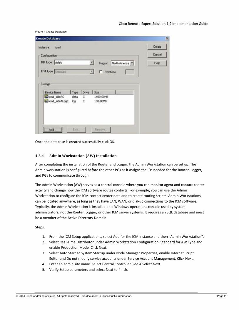
Figure 4 Create Database
Once the database is created successfully click OK.
4.3.4 Admin Workstation (AW) Installation
After completing the installation of the Router and Logger, the Admin Workstation can be set up. The Admin workstation is configured before the other PGs as it assigns the IDs needed for the Router, Logger, and PGs to communicate through.
The Admin Workstation (AW) serves as a control console where you can monitor agent and contact center activity and change how the ICM software routes contacts. For example, you can use the Admin Workstation to configure the ICM contact center data and to create routing scripts. Admin Workstations can be located anywhere, as long as they have LAN, WAN, or dial-up connections to the ICM software. Typically, the Admin Workstation is installed on a Windows operations console used by system administrators, not the Router, Logger, or other ICM server systems. It requires an SQL database and must be a member of the Active Directory Domain.
Steps:
1. From the ICM Setup applications, select Add for the ICM instance and then "Admin Workstation". 2. Select Real-Time Distributor under Admin Workstation Configuration, Standard for AW Type and
enable Production Mode. Click Next. 3. Select Auto Start at System Startup under Node Manager Properties, enable Internet Script
Editor and Do not modify service accounts under Service Account Management. Click Next. 4. Enter an admin site name. Select Central Controller Side A Select Next. 5. Verify Setup parameters and select Next to finish.

Cisco Remote Expert Solution 1.9 Implementation Guide
© 2014 Cisco and/or its affiliates. All rights reserved. This document is Cisco Public Information. Page 24
After the AW installation is complete, you must initialize the local database. The initialize database dialogue will appear after the Admin Workstation module installation is completed.
When you install a Distributor Admin Workstation, ICM Setup automatically sizes and creates a local database on the machine. Because this database is constantly overwritten by new data, the database size remains fairly constant. You normally do not need to resize the Distributor Admin Workstation (AW) real-time database. If you do need to resize the Distributor AW database, you can do so using the ICM Database Administration (ICMDBA) tool.
4.3.5 Admin Workstation (AW) Configuration
Each peripheral communicates with ICM software through a Peripheral Gateway, called a PG. The PG is a computer that communicates directly with the ACD, PBX, VRU, or Call Manager at a contact center, monitoring status information from the peripheral and sending it to the ICM system's Central Controller. If the peripheral acts as a routing client, the PG sends routing requests to ICM software.
The PG can be a single-simplex computer or a pair of duplexed computers. A single PG can service more than one peripheral; however, each peripheral uses only one PG.
Before adding the peripheral gateways to the UCCE Servers, they must first be created in the Admin Workstation Configuration Manager. This generates the peripheral IDs that are necessary for the PG/PIM installations.
To create the peripheral gateways in Configuration Manager there must first be an Agent Desk Settings List entry as it is one of the required settings under a PG controller configuration.
In the following sections we will take a look at some basic configurations in the Admin Workstation Configuration Manager that are required for Contact Center setup in Remote Expert.
4.3.6 Agent Desk Settings
1. Open the Configurations Manager on the AW. 2. Select the Agent Desk Settings List option under the Tools -->Explorer Tools group. 3. Click Retrieve. 4. Click Add. 5. Enter an appropriate list name such as Agent_Desk_Settings_1. 6. Enter a proper description. 7. Set the Ring no Answer time to 60. 8. Set the Wrap up time to 20. 9. Click Save.
Figure 5

Cisco Remote Expert Solution 1.9 Implementation Guide
© 2014 Cisco and/or its affiliates. All rights reserved. This document is Cisco Public Information. Page 25
To create the peripheral gateways in Configuration Manager, there must also be a Media Routing Domain list entry as it is one of the required settings under a PG controller configuration.
4.3.7 Media Routing Domain
1. Open the Configurations Manager on the AW. 2. Select the Media Routing Domain List option under the Tools --> Explorer Tools group. 3. Click Retrieve. 4. Click Add. 5. Enter an appropriate list name such as Cisco_Voice. 6. Enter a proper description. 7. Set the Media Class to Cisco_Voice. 8. Click Save
Figure 6

Cisco Remote Expert Solution 1.9 Implementation Guide
© 2014 Cisco and/or its affiliates. All rights reserved. This document is Cisco Public Information. Page 26
Once the Agent Desk setting list and the Media Routing Domain have been created, the new PG logical controllers for the Call Manager and CVP can be created.
There are several methods for creating PGs and their underlying Peripheral Interface Managers (PIMS). For this solution, only 1 PG is created. It is a Generic PG and has the CUCM and VRU_CVP PIMS. The PG Explorer on the AW Configuration Manager generates and maintains PG records for a logical interface controller, a physical interface controller, associated peripherals, and, if appropriate, an associated routing client.
4.3.8 Peripheral gateway logical controller
1. Open the Configurations Manager on the AW. 2. Select the PG Explorer option under the Tools --> Explorer Tools group. 3. Click Retrieve. 4. Click Add PG. 5. Enter an appropriate name such as Generic_PG_1. 6. Enter a proper description. 7. Set the client type to PG Generic. 8. Set the IP address for the CTI Server. 9. Click Save.
After clicking save, the logical and physical controller IDs will be automatically generated. Note them for later use when installing the peripheral gateways in ICMSetup later.

Cisco Remote Expert Solution 1.9 Implementation Guide
© 2014 Cisco and/or its affiliates. All rights reserved. This document is Cisco Public Information. Page 27
Figure 7
After creating the logical controller, the first of the underlying peripherals can now be added as follows:
1. Select the Generic_PG_1 PG that was just added from the PG explorer results on the left. 2. Click Add Peripheral. 3. Enter an appropriate peripheral name such as CCM_PIM. 4. Select the Client Type as Call Manager/SoftACD. 5. Select the Default Desk Settings option that was created earlier Agent_Desk_Settings_1. 6. Enter a proper description. 7. Check the Enable post routing option. 8. Then Click Save.
After clicking “Save” the peripheral ID will be automatically generated. Note this for later use when installing the peripheral gateways in ICM Setup.

Cisco Remote Expert Solution 1.9 Implementation Guide
© 2014 Cisco and/or its affiliates. All rights reserved. This document is Cisco Public Information. Page 28
Figure 8
Select the Routing Client tab and enter the following information for the peripheral:
1. Enter an appropriate name and Peripheral name such as CUCM_RC. 2. Select the Client Type as PCC/Enterprise Agent. 3. Select the Default media routing domain option to Cisco_Voice. 4. Enter a proper description. 5. Click Save.
Figure 9
6. On the Default Route tab ensure that Cisco_Voice is selected.

Cisco Remote Expert Solution 1.9 Implementation Guide
© 2014 Cisco and/or its affiliates. All rights reserved. This document is Cisco Public Information. Page 29
Figure 10
After the creation of the CUCM peripheral the second CVP VRU peripheral can now be added as follows:
1. Select the Generic_PG_1 PG that was added from the PG explorer results on the left. 2. Click Add Peripheral. 3. Enter an appropriate name and peripheral name such as VRU_PIM. 4. Select the Client Type as VRU. 5. Select the Default Desk Settings option to NONE. 6. Enter a proper description. 7. Check the Enable post routing option. 8. Click Save.
After clicking Save, the peripheral ID will be automatically generated; note it for later use when installing the peripheral gateways in ICMSetup.

Cisco Remote Expert Solution 1.9 Implementation Guide
© 2014 Cisco and/or its affiliates. All rights reserved. This document is Cisco Public Information. Page 30
Figure 11
Select the Routing Client tab and enter the following information for the peripheral:
1. Enter an appropriate name and Peripheral name such as VRU_RC. 2. Select the Client Type as VRU. 3. Select the Default media routing domain option to Cisco_Voice. 4. Enter a proper description. 5. Click Save.
Figure 12

Cisco Remote Expert Solution 1.9 Implementation Guide
© 2014 Cisco and/or its affiliates. All rights reserved. This document is Cisco Public Information. Page 31
Once all of the peripheral gateways and peripheral interface managers have been created in the Admin Workstation Configuration Manager the Peripheral Gateway (PG) can then be installed in the ICM servers.
4.3.9 Network VRU Configuration
Steps:
1. Open the Configurations Manager on the AW. 2. Select the Network VRU Explorer option under the Tools --> Explorer Tools group. 3. Click Retrieve. 4. Click Add Network VRU. 5. Enter an appropriate name such as "cvp". 6. Select the type as "Type 10". 7. Enter a description such as the extension numbers associated with CVP and the VXML Gateway. 8. Then Click Save.
Perform the same steps and add a label for the CVP VRU PIM Route client as follows:
1. Click Add Label. 2. Select the Network VRU cvp. 3. Select the Route Client CVP_VRU_PIM. 4. Enter the label being returned to CVP. 5. Select normal for the label type. 6. Select icm as the Customer. 7. Enter a description as desired. 8. Click Save.
Figure 13
After the network VRUs have been created, add a Contact Center Agent and Skill Group for testing purposes.
4.3.10 Add Agents
Create Agents as follows:
1. Open the Configurations Manager on the AW.

Cisco Remote Expert Solution 1.9 Implementation Guide
© 2014 Cisco and/or its affiliates. All rights reserved. This document is Cisco Public Information. Page 32
2. Select the Agent Explorer option under the Tools --> Explorer Tools group. 3. Click Retrieve. 4. Click Add Agent. 5. Enter an appropriate first, last, and login name. 6. Enter an appropriate password. 7. Verity the Enterprise name that was generated is appropriate. 8. Enter an Agent ID number or allow one to be generated automatically. This number is used
during agent login to the Agent desktop client. 9. On the Supervisor tab, check Supervisor agent if desired. 10. Click Save. 11. Repeat above steps to add all the agents.
4.3.11 Add Skill Group
Create a Skill Group as follows:
1. Open the Configurations Manager on the AW. 2. Select the Skill Group Explorer option under the Tools --> Explorer Tools group. 3. Click Retrieve. 4. Click Add Skill Group. 5. Enter a Peripheral name such as PreSale. 6. Enter an appropriate Name such as Generic_Presale. 7. Select the Media Routing domain Cisco_Voice. 8. On the Skill Group Members tab click add and select the agent created earlier. 9. Click Save. 10. Add route option in the skill group. 11. Click Add Route. 12. Assign an appropriate name such as Generic_PreSale_Route. 13. Click Save.
The next step is to create Call Type Lists.
4.3.12 Add Call Type List
Create a Call Type List as follows:
1. Open the Configurations Manager on the AW. 2. Select the Call Type List option under the Tools --> Explorer Tools group. 3. Click Retrieve. 4. Click Add. 5. Enter a name such as call_type_1 6. Select the Customer icm. 7. Enter an appropriate description as desired. 8. Click Save.
Figure 14

Cisco Remote Expert Solution 1.9 Implementation Guide
© 2014 Cisco and/or its affiliates. All rights reserved. This document is Cisco Public Information. Page 33
4.3.13 Add Dialed Number/Script Selector List
Create a Dialed Number List as follows:
1. Open the Configurations Manager on the AW. 2. Select the Dialed Number/ Script Selector List option under the Tools --> Explorer Tools group. 3. Click Retrieve. 4. Click Add. 5. Select the Routing client CUCM_RC. 6. Select the Media routing Domain Cisco_Voice. 7. Enter the Dialed Number string that is called to reach this queue. 8. Enter a name such as CUCM_RC.1000 or CUCM_RC.1333 as appropriate. 9. Select the Customer icm. 10. Leave the default Label as <None>. 11. Enter an appropriate description as desired. 12. Click Save. 13. Repeat for additional dialed numbers. 14. On the Dialed Number Mapping Tab, select the calling line ID, Caller Entered digits (if any) and
the Call type.
Figure 15

Cisco Remote Expert Solution 1.9 Implementation Guide
© 2014 Cisco and/or its affiliates. All rights reserved. This document is Cisco Public Information. Page 34
4.3.14 Enable Expanded Call Context
To ensure proper call routing, ensure that Expanded call context is enabled in the System information configuration as follows:
1. Open the Configurations Manager on the AW. 2. Select the System Information option under the Configure ICM --> Enterprise --> System
Information group. 3. Check the Expanded call context option. 4. Click Save.
4.3.15 ICM Instance Explorer Setting
An additional customer definition must be created for CVP under the ICM instance.
Create a customer definition as follows:
1. Open the Configurations Manager on the AW. 2. Select the ICM Instance Explorer option under the Tools --> Explorer Tools group. 3. Click Retrieve. 4. Select the desired instance. 5. Click Add Customer definition.

Cisco Remote Expert Solution 1.9 Implementation Guide
© 2014 Cisco and/or its affiliates. All rights reserved. This document is Cisco Public Information. Page 35
6. Enter an appropriate name. 7. Select the Network VRU as cvp. 8. Enter an appropriate description as desired. 9. Click Save.
4.3.16 Add Expanded Call Variable List
Call variables are used to carry various pieces of information between systems as a call flows through the queue script steps. The default installation lacks several variables used in an Expert Advisor deployment and as such need to be added.
Add additional call variables as follows:
1. Open the Configurations Manager on the AW. 2. Select the Expanded Call Variable List option under the Tools --> Explorer Tools group. 3. Click Retrieve. 4. Click Add. 5. Using the table of information below, configure each variable. 6. Enter the variable name. 7. Set the variable maximum length. 8. If an array size is defined, check the array option and set the size. 9. Set the variable as enabled. 10. Set as persistent if specified. 11. Enter an appropriate description as desired. 12. Click Save. 13. Repeat for each call variable.
Table 1
Expanded Call Variables
Name Max Length Array size Enabled Persistent
user.cvpmovies_bg_media 40 yes
user.h323.rftransfer 1 Yes
user.media.id 36 Yes
user.microapp.app_media_lib 10 Yes
user.microapp.caller_input 210 Yes
user.microapp.charset 10 Yes Yes

Cisco Remote Expert Solution 1.9 Implementation Guide
© 2014 Cisco and/or its affiliates. All rights reserved. This document is Cisco Public Information. Page 36
Expanded Call Variables
Name Max Length Array size Enabled Persistent
user.microapp.currency 6 Yes
user.microapp.cvpmovies_params 40 Yes
user.microapp.error_code 2 Yes
user.microapp.FromExtVXML 210 1 Yes
user.microapp.grammar_choices 210 Yes
user.microapp.inline_tts 210 Yes
user.microapp.input_type 1 Yes
user.microapp.locale 5 Yes
user.microapp.media_server 30 Yes
user.microapp.metadata 62 Yes
user.microapp.override_cli 1 Yes
user.microapp.pd_tts 1 Yes
user.microapp.play_data 40 Yes
user.microapp.recording 40 Yes
user.microapp.sys_media_lib 10 Yes
user.microapp.ToExtVXML 210 1 Yes
user.microapp.uui 131 Yes
user.microapp.UseVXMLParams 1 1 Yes

Cisco Remote Expert Solution 1.9 Implementation Guide
© 2014 Cisco and/or its affiliates. All rights reserved. This document is Cisco Public Information. Page 37
Expanded Call Variables
Name Max Length Array size Enabled Persistent
user.sip.refertransfer 1 Yes
user.video_media_server 40 Yes
4.3.17 Network VRU Script List
The Network VRU enables interaction with the caller using a variety of external scripts. The scripts created in the Network VRU Script List are then made available in the Script Editor.
Create the VRU Scripts as follows:
1. Open the Configurations Manager on the AW. 2. Select the Network VRU Script List option under the Tools --> Explorer Tools group. 3. Click Retrieve. 4. Click Add. 5. Create a network VRU Script for playing silence while Customer is in Video Queue. 6. Enter the script name. 7. Set the Network VRU as cvp for all entries. 8. Enter the VRU script name. 9. Enter the Timeout length. 10. Enter the Configuration parameter. 11. Set the Customer as icm. 12. Enter an appropriate description as desired. 13. Click Save.

Cisco Remote Expert Solution 1.9 Implementation Guide
© 2014 Cisco and/or its affiliates. All rights reserved. This document is Cisco Public Information. Page 38
Figure 16
4.3.18 Reroute on No Answer (RONA) configuration
When a call is routed to an agent but the agent fails to answer the call within a configurable amount of time, the Cisco Call Manager PIM for the agent who did not answer will change that agent's state to "not ready" (so that the agent does not get more calls) and launch a route request to find another agent. Any call data is preserved and popped onto the next agent's desktop. If no agent is available, the call can be sent back to the IP IVR for queuing treatment again. Again, all call data is preserved. The routing script for this RONA treatment should set the call priority to "high" so that the next available agent is selected for this caller. In the agent desk settings, you can set the RONA timer and optionally the DN used to specify a unique call type and routing script for RONA treatment.
In Order to configure RONA complete these steps:
1. In the ICM Script Editor, open the applicable script, and enable router requery on the Queue to Skill Group node.
2. Under the Agent Desk Settings configuration, set the Ring No Answer Time to the maximum time you want to allow the agent to answer the call. For example, set this to eight seconds to give the agent two rings before the call is rerouted through RONA. This timer must be shorter than the no answer time-out for router requery. See step 4.

Cisco Remote Expert Solution 1.9 Implementation Guide
© 2014 Cisco and/or its affiliates. All rights reserved. This document is Cisco Public Information. Page 39
3. Use the DN Pattern Outbound Invite Timeout option in the CVP Operations Console's SIP Service configuration tab in order to add the expiration timeout for a particular dialed number pattern.
4. Ensure that the No Answer Ring Duration on the DN in Cisco Unified Communications Manager is set to a value higher than the Cisco Unified Customer Voice Portal timeout timer. The default for this in Cisco Unified Communications Manager is 20 seconds.
The timer hierarchy for these three settings looks like this:
Agent Desktop < CVP Invite Timeout < Cisco Unified Communications Manager CFW Example: 10 seconds < 12 secs < 20 seconds CFW
4.3.19 Peripheral Gateway (PG) Installation
Each contact center device (ACD, PBX, or IVR/VRU) communicates with ICM software through a Peripheral Gateway (PG). The PG reads status information from the device and passes it back to the ICM software. The PG runs one or more Peripheral Interface Manager (PIM) processes, which are the software components that communicate with proprietary ACD and IVR/VRU systems.
Before you install a Peripheral Gateway (PG), the Windows operating system (for version specifics refer to the Cisco Intelligent Contact Management Software Release 9.0(1) Bill of Materials—including SNMP and (for Windows 2008 R2) WMI—must be installed on the computer, you must have setup the Windows Active Directory services for ICM software, and you must have setup at least one ICM instance.
Further, before you can complete the installation of a Peripheral Gateway, you must create configuration records in the ICM database. To create these configuration records you must have installed the Call Router, a Logger, and the Admin Workstation.
To configure a PG, you must know the visible network addresses for the Call Router machines. If the PG is duplexed, you must know the visible and private network addresses of its duplexed peer.
On the servers selected for the peripheral gateways start the ICMSetup.exe application. At least one ICM instance must be added before you can install any ICM components.
In the Cisco ICM Setup dialog box, in the ICM Instances section, click Add. The Add Instance dialog box opens.
Complete the following steps:
1. Select the network Domain for the instance. 2. Select the Facility Organizational Unit for the instance. 3. Select the Instance Name for the instance. 4. Use the Instance Number generated by the ICM software. (For standard single-instance ICM
configurations, the instance number is 0.) 5. Click OK.

Cisco Remote Expert Solution 1.9 Implementation Guide
© 2014 Cisco and/or its affiliates. All rights reserved. This document is Cisco Public Information. Page 40
4.3.20 PG Installation
Steps:
1. In the ICM Setup application, click the Add button on the right under Instance Components. 2. A new dialogue window will appear where you will be able to select the Peripheral Gateway
component. In the Peripheral Gateway properties window configure the following: a. Check the Production node. b. Check the Auto start at system startup. c. Check the duplexed Peripheral Gateway. d. Set the PG Node Properties ID to PG 1 and select the appropriate side for duplexed
installations. e. Select the following client types and click the Add button:
- Call Manager - VRU
f. Click Next. 3. For the Peripheral Gateway Component Properties click Add in the Peripheral Interface
Managers section. 4. Set the Client type as Call Manager and select PIM 1 from the Available PIMS List. Click OK. 5. In the PIM Configuration dialogue, configure the PIM as follows:
a. Select Enable. b. Enter an appropriate Peripheral name. c. Enter the Peripheral ID that was assigned by the Configuration Manager on the Admin
Workstation. d. Specify the appropriate agent Extension length for DN's on the Cisco Unified
Communication Manager (this is critical as additional digits are added for call handling to CVP and call handoff will fail when mismatched).
e. In the Call Manager Service Parameter enter the IP address of the call manager cluster publisher.
f. Enter the CCE username and password created in the Call Manager (i.e. JTAPI user). g. Click OK.

Cisco Remote Expert Solution 1.9 Implementation Guide
© 2014 Cisco and/or its affiliates. All rights reserved. This document is Cisco Public Information. Page 41
Figure 17
6. Back on the Peripheral Gateway Component Properties click Add in the Peripheral Interface Managers section again. Set the Client type as VRU and select PIM 2 from the Available PIMS List. Click OK.
7. In the PIM Configuration dialogue, configure the PIM as follows: a. Select Enable. b. Enter an appropriate Peripheral name. c. Enter the Peripheral ID that was assigned by the Configuration Manager on the Admin
Workstation. d. In the VRU Hostname enter the IP address of the CVP Server. e. Enter VRU connection port. f. Click OK.
Figure 18
8. In Peripheral Gateway Component Properties enter the Peripheral Gateway Logical controller ID that was generated by the Configuration Manager on the Admin Workstation and click Next.
9. On the Device Management Protocol Properties set Side A preferred option and click Next.

Cisco Remote Expert Solution 1.9 Implementation Guide
© 2014 Cisco and/or its affiliates. All rights reserved. This document is Cisco Public Information. Page 42
10. Enter the name or IP addresses for the Visible and Private Interfaces of the PG and Router. Optionally, enable QoS for these interfaces as desired. Click Next.
11. Review the PG setup information and click Next to complete installation of the first PG. Peripheral Gateways
4.3.21 JTAPI Client Installation
It is mandatory to install the JTAPI client on the CUCM PG (which is PG1 in this setup) machine, so that it can talk to the CUCM via JTAPI interface. Once this has been completed, there will be a new process called JTAPIGW, which should be active even if no agents or phones are created in the CUCM. Associate all of the agent's phone devices with this user in CUCM as well. To install the JTAPI client, download the client from the CUCM administration interface and install it on the PG1 machine.
Figure 19 Cisco Unified CM Administration
Within the Cisco Unified CM Administration interface select Application and then Plugins. Click the Find button to list all available plug-ins. Download and install the Cisco JTAPI for Windows plug-in.
After completion of the JTAPI plug-in, install the CTI Server.

Cisco Remote Expert Solution 1.9 Implementation Guide
© 2014 Cisco and/or its affiliates. All rights reserved. This document is Cisco Public Information. Page 43
4.3.22 CTI Server Installation
Cisco supports installation of CTI Server on the same machine where the Peripheral Gateway software is installed. Installing CTI Sever on a machine separate from the PG may cause network problems including, but not limited to, network disconnects, agents missing calls, and agents forced into Not Ready.
Before installing CTI Server, you must have installed/set up all the other components of ICM as described in the preceding sections.
CTI Server (ctisvr) is also called CG (short for CTI Gateway), which connects to the CTI OS Server using the ctidriver service running on the CTI OS Server machine.
In the ICM Setup application, click the Add button on the right under Instance Components.
A new dialogue window will appear where you will be able to select the CTI Server component.
In the CTI Server properties window configure the following:
1. Check the Production node. 2. Check the Auto start at system startup. 3. Check the duplexed Peripheral Gateway. 4. Set the CG Node Properties ID to CG 1 and select the appropriate side for duplexed installations. 5. Click Next. 6. CTI Server as a default connects to the CTIOS Server on port 42027, but can be configured to use
a different port. Click Next. 7. Configure the PG and CG Public and Private interfaces. Click Next. 8. Review the CG setup information and click Next to complete installation of the CTI Gateway.
4.3.23 CTI OS Server Configuration
The Computer Telephony Integration Object Server (CTI OS) is Cisco's next generation customer contact integration platform. CTI OS combines a powerful, feature-rich server and an object-oriented software development toolkit to enable rapid development and deployment of complex CTI applications.
Refer to the CTI OS System Manager's Guide for Cisco ICM/IPCC Enterprise & Hosted Editions for a complete explanation of configuring peripherals and connection profiles in the CTI OS Server.
From the Server directory on the CD, run Setup.exe (or if already installed C:\icm\CTIOS_bin\setup.exe). Click Yes on the Software License Agreement screen. The CTI OS Instances dialog appears.
1. The CTIOS Instances dialog allows you to create CTI OS Instances and add CTI OS Servers to a configured instance of CTI OS. You will create only one CTI OS instance for each ICM instance.
2. Under the CTI OS Instance List, click Add. 3. Enter an instance name (e.g., "ctios"). 4. Now click on Add inside the CTI OS Server List. The Add CTIOS Server dialog appears. 5. The CTIOS Server Name is filled in with the string "CTIOS" followed by the next available index for
a CTI OS Server. If a CTI OS Server has been deleted, the CTIOS Server Name string is filled in with the index that was deleted.

Cisco Remote Expert Solution 1.9 Implementation Guide
© 2014 Cisco and/or its affiliates. All rights reserved. This document is Cisco Public Information. Page 44
6. If you are installing CTI OS Server for the first time, an Enter Desktop Drive screen appears. Accept the default installation drive or select another drive from the pull down list.
7. The Peripheral ID here is the same ID that was assigned during the CUCM PG configuration in the Configuration Manager on AW. The agent desktop communicates with the CUCM IP Phone.
8. The listen port is where CTI Desktop Agent will connect. This port will also be used if a secondary CTIOS Server wants to talk to this one in an high availability environment or setting.
9. Enter the default-polling interval for Skill group statistics (in seconds). Click Next. 10. The Peer CTIOS Server dialog is used to configure a CTI OS Peer Server. It is also used for Chat and
CTI OS Silent Monitoring. Enter the appropriate information. After you click Finish, and the files are laid down, the service is registered, and Registry entries are made.
11. The Security installation is launched. 12. If you wish to disable Security, just click OK; otherwise, check the checkbox and enter the
appropriate information, and click OK.
Upon the completion of the CTI OS Server the next step is to create device targets in Configuration Manager. Device targets are the extensions used by the formal Contact Center agents when the login into the Agent Desktop application. These next configuration steps are for formal contact center agents that would be used in addition to the Expert advisor agents. It is recommended to install a few formal agents for testing prior to the completed Expert Advisor implementation.
4.3.24 ICM Script for Expert/Agent Routing and Audio in Queue
Create and schedule a routing script on AW by using the Script Editor software. The logic that is followed for creating this script is as follows:
1. Start the script with the start node. 2. Set the value of DN node to the suitable VRU_RC (the pilot point DN), which would match the
dialed number, sent to ICM by CVP. 3. Set the value of media server HTTP URL in Call.user.microapp.media_server variable. This is the
web server URL from where .wav files will be played (e.g., http://media.cisco-irn.com). 4. Set the value of language in Call.user.microapp.locale as en-us. 5. Set the value of input type (which is digits in this sample script) in Call.user.microapp.input_type
variable to D. 6. Set the value of the Call.user.microapp.app_media_lib to app. 7. After setting the variables send the call to IVR using "Run External Script" node. 8. Run external script called "silence" that will play the silence tone to the customer when the
customer is put in queue. This is done because, in Remote Expert, there is a Video In Queue (ViQ) being configured which plays video and audio to the Customer while in queue and setting any other media file here would conflict with the desired ViQ being played back to the customer.
9. Use an “If” node to determine if the call stays in the queue for longer than x seconds and send the call to a different skill group if the condition is met. Send false condition to skill group with experts configured with video capabilities and True condition to skill group with audio only experts for example.
10. In either case, send the call to “Queue to skill group” node and select the desired skill group. 11. Add “Run external script” and “Release Call” nodes from the Queue to skill group node for both
success and failure conditions respectively. If the call is queued and no agent is in “Ready” state

Cisco Remote Expert Solution 1.9 Implementation Guide
© 2014 Cisco and/or its affiliates. All rights reserved. This document is Cisco Public Information. Page 45
the call will be queued and the media file configured in “Run external script” node will be played to the customer.
Figure 20
Once the script has been complete, it needs to be activated. Follow the steps below to activate the script:
1. Pull Down ‘Script’ menu and select ‘Call Type Manager’. 2. Select ‘Dialed Number’. Add or Modify. 3. Select ‘Call Type’ 4. Select ‘Schedule’ and select schedule and script. Add/Modify to select script / period.
4.3.25 Component Checkpoint: Verify UCCE Integration
• Verify UCCE Node --> Diagnostic framework shows all processes with healthy status. • Verify SQL installation went through successfully on Logger and AWHDS • Verify that you are able to login to the database on Logger and AWHDS • Verify that AWHDS is able to open configuration manager. • Verify that when you open the script manager you do not get an error – this confirms that the
AW distributor is alive and talking clean with the UCCE Logger. • Verify integration of UCCE components
4.4 Customer Voice Portal Server Configuration Unified CVP components can be deployed using the single OVA on any CVP supported virtualization hardware. Virtualization of the following deployments and Unified CVP components on Cisco Unified Communications Systems (UCS) hardware is supported:

Cisco Remote Expert Solution 1.9 Implementation Guide
© 2014 Cisco and/or its affiliates. All rights reserved. This document is Cisco Public Information. Page 46
1. Unified CVP Call/Media Server 2. Unified CVP VXML Server 3. Unified CVP Reporting Server 4. Unified CVP Ops Console
For the Cisco Remote Expert Solution, we would require only the CVP Call/Media Server and CVP OAMP (Ops Console) specifically. We proceed through this document assuming the CVP Call Server and CVP OAMP server are installed based on the guidance from the CVP 10.0 Design Guide. The sections that follow focus on the configurations associated with setting up CVP for the Cisco Remote Expert Solution.
4.4.1 CVP Media Server Configuration
This setup uses Microsoft IIS as the web server to host the media files.
Steps:
1. The CVP installation places some basic media files in the IIS web server path C:\ inetpub\wwwroot\en-us\app.
2. Either create a Virtual Directory linking to the Media Files installed by the CVP setup.exe in the above path, or link to the "en-us" folder in the root of the IIS Web server.

Cisco Remote Expert Solution 1.9 Implementation Guide
© 2014 Cisco and/or its affiliates. All rights reserved. This document is Cisco Public Information. Page 47
3. Make sure anonymous access is enabled and the built-in IIS User is assigned.

Cisco Remote Expert Solution 1.9 Implementation Guide
© 2014 Cisco and/or its affiliates. All rights reserved. This document is Cisco Public Information. Page 48
4. Create a folder named Custom below the en-us folder if you would like to place your custom media files in a new location. In our case we would need to place the silence.wav file on the media server in a desired location.
5. Apply configuration changes and save. 6. Restart IIS
We need to ensure to point to the silence.wav file in the ICM script (the audio to be played to the endpoint when placed in queue) and you should be able to access this file from any compatible browser using for example http://cvp_server/en-us/app/silence.wav.
4.4.2 CVP Configuration
Before configuring CVP call server, it should be important to know little bit about the setup and SIP call flows.
Table 2 High Level CVP Call Flow Overview
High Level CVP call flow overview
CUCCE Pilot Number
IP Phone caller dials CTI route point number 3333
Routing Client SIP Gateway is the routing client
Label Returned to SIP GW by ICM
123456789+cid
Processing at CVP CVP Call Server send this label 123456789+cid to VXML-GW
Processing at VXML-GW
VXML-GW has an incoming dial-peer configured that basically invokes the bootstrap tcl service
Processing at VXML-GW
Now a sequence of VXML communications happens between the VXML GW and CVP IVR Service. This communication is called MicroApps.
Processing at CVP At this point CVP sends the same label 123456789+cid to ICM to inform that VXML-GW resources are engaged
Queue music ICM instructs CVP to play custom music to the endpoint based on the script configuration.
Once you understand the high level overview of the call flow, it will be easy to understand the static routes needed by the CVP Call Server.

Cisco Remote Expert Solution 1.9 Implementation Guide
© 2014 Cisco and/or its affiliates. All rights reserved. This document is Cisco Public Information. Page 49
4.4.3 CVP Operations Console
Unified CVP provides Voice over IP (VoIP) routing services for the Cisco Unified Intelligent Contact Management Enterprise (Unified ICME) and Cisco Unified Contact Center Express (UCCX) products. Unified ICME provides the services necessary to determine where calls should be routed, whether to ACDs, specific agents, or to VRUs, but the routing services themselves must be provided by an external routing client.
A typical deployment of the Unified CVP solution requires operating, administering, managing and provisioning multiple servers and IOS components. The Operations Console is a web-based console that enables users to centrally operate, administer, maintain and provision the Unified CVP solution.
We would be adding the CVP Call server and the VXML GW information and other CVP configuration using the CVP Operations Console or the CVP OAMP platform.
4.4.4 CVP Call Server
CVP call server talks to the VRU pim that was earlier configured as part of the ICM setup. The VRU pim exists on the Peripheral Gateway of the ICM and it enables routing messages between CUCM and ICM in addition to serving as a media server to play back ICD prompts.
Steps:
1. Login to CVP Operations console as administrator 2. Proceed to Device Management --> Unified CVP Call Server 3. Click on Add New. 4. Provide the CVP Call server IP Address and hostname. Also enable to ICM, IVR and SIP services.
Ensure that the device version and build information displayed is correct. 5. You can choose to leave the ICM and IVR tabs with default configurations since it doesn’t affect
our RE call flow. 6. Proceed to SIP service tab. Here, if you are using DNS SRV to resolve server farm names or
service names, please enable this option and select the DNS SRV server/outbound proxy host details that proceeds below.
7. Enter 91919191 in the ‘DN on the gateway to play ringtone’ and 92929292 for the ‘DN on the gateway to play the error tone’ fields unless you are planning to use a different DN in the vxml gateway configuration.
8. Save and Deploy.

Cisco Remote Expert Solution 1.9 Implementation Guide
© 2014 Cisco and/or its affiliates. All rights reserved. This document is Cisco Public Information. Page 50
Figure 21
Figure 22
4.4.5 VXML Server
All values are left at the default configuration as shown below.
Figure 23

Cisco Remote Expert Solution 1.9 Implementation Guide
© 2014 Cisco and/or its affiliates. All rights reserved. This document is Cisco Public Information. Page 51
4.4.6 CUCM Server
All values are left at the default configuration as shown below.
Figure 24
4.4.7 VXML Gateway
The vxml gateway configuration is added to the Operations console in order to identify and be able to communicate with the vxml gateway where the tcl services reside.
Steps:
1. Login to the CVP operations console as Administrator user. 2. Proceed to Device Management --> Gateway. 3. Click on Add New. 4. Provision the correct vxml gateway IP Address, Hostname and Device Type. 5. On the right panel enter the correct credentials and port information (telnet/ssh) that is used to
login to the gateway ios. Click on Test Sign-in to confirm the configuration. 6. Click on Save and deploy.
Figure 25
Once this is complete proceed to Bulk Transfer --> File Transfer --> Scripts and Media. Select gateway from ‘Select Device Type’ and move the newly configured gateway from the Available frame to the Selected frame. Select ‘Default Gateway files’ from the Scripts and Media files box and click on Transfer. Confirm the status using the File Transfer Status button. This ensures that the right version of scripts and

Cisco Remote Expert Solution 1.9 Implementation Guide
© 2014 Cisco and/or its affiliates. All rights reserved. This document is Cisco Public Information. Page 52
media files are placed on the vxml gateway by transferring those files from the CVP to the gateway using either ssh or telnet that was configured earlier.
Once this is complete, follow the steps in Quick Steps: 1-6 to add CUBE as a gateway to the CVP Operations console.
4.4.8 SIP Server for VXML Gateways
Figure 26 Edit SIP Server Group
4.4.9 CVP Media Server
The discussed earlier Media Server is the server on which the media files reside. It is a good practice to configure this server using the Operations Console.
Steps:
1. Login to the CVP operations console as Administrator user. 2. Proceed to Device Management --> Media Server. 3. Click on Add New. 4. Provision the Media Server IP Address and Hostname details.

Cisco Remote Expert Solution 1.9 Implementation Guide
© 2014 Cisco and/or its affiliates. All rights reserved. This document is Cisco Public Information. Page 53
4.4.10 Dialed Number Pattern
This is where we configure the routing on the CVP. It is similar to using Route Patterns in the Cisco Unified Communications Manager if you are comfortable with the CUCM method.
Steps:
1. Login to the CVP operations console as Administrator user. 2. Proceed to System --> Dialed Number Pattern. 3. Click on Add New. 4. Enter the label returned by ICM for the given call flow as the Dialed Number Pattern. Use ‘>’ as a
wild card to correlate with ‘X’ used in CUCM. 5. Proceed to the Dialed Number Pattern Types and select ‘Enable Local Static Route’ 6. In the Route to Device, select the VXML gateway from the dropdown. 7. The IP Address, Host Name, Server group name gets auto populated. 8. Click Save. 9. Complete the configuration by clicking on Deploy. If Deploy is not clicked, the configuration
doesn’t take effect.
CVP contains the following dialed pattern numbers
1. Agent DN’s, 2xxxx route calls to CUBE. 2. Agent DN’s, 1xxxx route calls to CUCM directly by-passing CUBE. This is for debugging purposes
only. 3. Ring Tone ,9191>, routes calls to VXML gateway. 4. Error Tone, 9292>, routes calls to VXML gateway. 5. Agent Queuing label, 9999>, routes calls to VXML gateway. This is for ViQ.

Cisco Remote Expert Solution 1.9 Implementation Guide
© 2014 Cisco and/or its affiliates. All rights reserved. This document is Cisco Public Information. Page 54
Figure 27
4.4.11 Miscellaneous
Listed below are few things that might help with the configurations from a CVP point of view.
1. You need to upload licenses before starting the configurations. You can do this by logging into Operations console and proceeding to Bulk Transfer --> File Transfer --> License. Select the license(s) from the local system and upload them into the CVP setup.
2. Every configuration added into CVP needs to be saved and then Deployed. Ensure that you click the ‘Deploy’ button once confirmed.
3. If you are deploying a Highly Available setup, it is good practice to do it using DNS SRV records added to the common DNS Server in the infrastructure. However CVP also gives you an option to configure the records locally on the call server/operations console and this is provided in the Call Server SIP configuration screen.
4. You can also configure SIP Server groups for configuring redundant components, which go into the Device Configuration menu.
5. Notices that CVP call flows are valid for the Type 10 VRU only. 6. Observe that "cid" is actually the correlation ID and is a numerical value. 7. It’s a good practice to take a backup once the configuration is complete. This can be done using
System --> Expert System backup and entering a valid location to take the backup.
4.4.12 Solution Checkpoint: Verify Call Routing
1. Check to confirm that on UCCE --> PG --> Diagnostic framework the VRU PIM is in Active state 2. Check to confirm that with ICM script in monitor mode, we see the call lodged at the
RunExtScript node 3. Check that the silence or the configured media is being played back with no experts
available/logged in

Cisco Remote Expert Solution 1.9 Implementation Guide
© 2014 Cisco and/or its affiliates. All rights reserved. This document is Cisco Public Information. Page 55
4. Dial pilot number from video endpoint to verify functionality
4.5 VXML Gateway Configuration Voice Extensible Markup Language (VXML) is a standard defined by the World Wide Web Consortium (W3C). VXML is designed to create audio dialogs that provide synthesized speech, recognition of spoken words, and recognition of DTMF digits and recordings of spoken audio. The VXML server and clients use the well-known HTTP protocol to exchange VXML documents and pages.
Cisco Voice Portal (CVP) delivers intelligent and interactive voice response (IVR) applications that can be accessed over the phone. There are three types of CVP deployments:
• Standalone Service • CVP Call Control • Call Queue and Transfer
Synthesized speech, recognition of spoken words or DTMF digit functionalities are provided by Text-to-Speech (TTS) and Automatic Speech Recognition (ASR) servers. Cisco IOS® VXML Gateway communicates with the TTS and ASR servers using Media Resource Control protocol (MRCP). There are two versions of MRCP (RFC 4463), namely MRCPv1 (MRCP over RTSP) and MRCPv2 (MRCP over SIP).
In this section we will do a high level walk through the vxml configuration pertaining to the Cisco Remote Expert Solution.
4.5.1 IOS Configuration
voice service voip ip address trusted list ipv4 10.0.133.181 !-- IP address of CVP server !--- forces early offer early-offer forced voice class codec 1 !--- requirement for Remote Expert solution. codec preference 1 g711ulaw ! !--- Define the amount of maximum memory to use for downloaded prompts. ivr prompt memory 15000 ! !--- Configure an application service for CVP VXML
CVPSelfServiceBootstrap.vxml. application service new-call flash:bootstrap.vxml ! !--- Specify the maximum memory size for the HTTP Client Cache. http client cache memory pool 15000 !--- Specify the maximum number of file that can be stored in the HTTP Client
Cache. http client cache memory file 500 !--- Disable Persistent HTTP Connections. no http client connection persistent !--- Dial-peer used to play ring tone to the customer
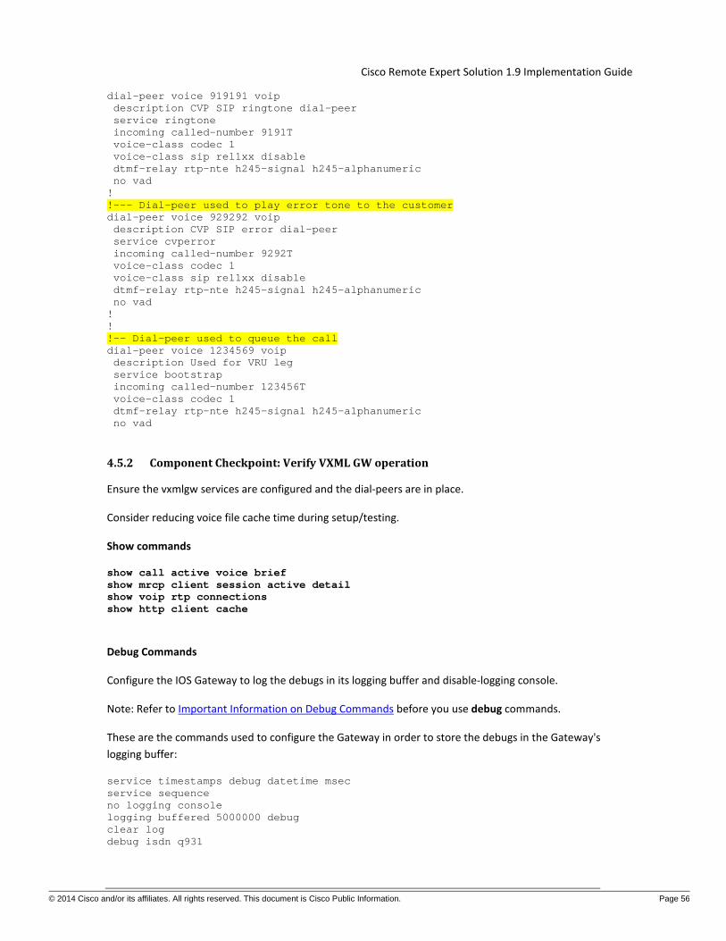
Cisco Remote Expert Solution 1.9 Implementation Guide
© 2014 Cisco and/or its affiliates. All rights reserved. This document is Cisco Public Information. Page 56
dial-peer voice 919191 voip description CVP SIP ringtone dial-peer service ringtone incoming called-number 9191T voice-class codec 1 voice-class sip rel1xx disable dtmf-relay rtp-nte h245-signal h245-alphanumeric no vad ! !--- Dial-peer used to play error tone to the customer dial-peer voice 929292 voip description CVP SIP error dial-peer service cvperror incoming called-number 9292T voice-class codec 1 voice-class sip rel1xx disable dtmf-relay rtp-nte h245-signal h245-alphanumeric no vad ! ! !-- Dial-peer used to queue the call dial-peer voice 1234569 voip description Used for VRU leg service bootstrap incoming called-number 123456T voice-class codec 1 dtmf-relay rtp-nte h245-signal h245-alphanumeric no vad
4.5.2 Component Checkpoint: Verify VXML GW operation
Ensure the vxmlgw services are configured and the dial-peers are in place.
Consider reducing voice file cache time during setup/testing.
Show commands
show call active voice brief show mrcp client session active detail show voip rtp connections show http client cache
Debug Commands
Configure the IOS Gateway to log the debugs in its logging buffer and disable-logging console.
Note: Refer to Important Information on Debug Commands before you use debug commands.
These are the commands used to configure the Gateway in order to store the debugs in the Gateway's logging buffer:
service timestamps debug datetime msec service sequence no logging console logging buffered 5000000 debug clear log debug isdn q931

Cisco Remote Expert Solution 1.9 Implementation Guide
© 2014 Cisco and/or its affiliates. All rights reserved. This document is Cisco Public Information. Page 57
debug voip ccapi inout debug voip application vxml default debug voip application vxml dump debug rtsp all debug mrcp all debug http client all debug voip rtp session nte named-event

Cisco Remote Expert Solution 1.9 Implementation Guide
© 2014 Cisco and/or its affiliates. All rights reserved. This document is Cisco Public Information. Page 58
5 Interactive Experience Manager
For installation and configuration details around Interactive Experience Manager and its components please refer to all the 2.1 product documentation available at:
Interactive Experience Manager Administration Guide
And
Interactive Experience Client Users Guide
Configuration Notes for IEC:
• To use DHCP to assign an IEM IP Address to the IEC, including the following in the DHCP configuration file:
option mms-server code 202 = string;
option mms-server "10.0.133.131";
5.1 IEM Configuration as Tested
Policy Configuration For the Remote Expert lab two policies are defined: one for IEC & TelePresence and one for iServices.
Figure 28
For both the IEC & TelePresence and the iServices IEM policies, the pertinent configuration is the browser startup URL configured. The REM’s ACE VIP is used in the browser startup URL.

Cisco Remote Expert Solution 1.9 Implementation Guide
© 2014 Cisco and/or its affiliates. All rights reserved. This document is Cisco Public Information. Page 59
Figure 29
Additional Policy Configuration is needed for the iServices kiosk. This configuration allows the iServices kiosk to register with the CUCM.
Figure 30

Cisco Remote Expert Solution 1.9 Implementation Guide
© 2014 Cisco and/or its affiliates. All rights reserved. This document is Cisco Public Information. Page 60
6 Remote Expert Manager
For installation and configuration of the Remote Expert Manager components please refer to the following documentation:
Remote Expert Manager
6.1 Video on Hold In this release of the Remote Expert solution, the video on-hold call treatment for the Immersive use case may be displayed to the customer using the touch screen in the Immersive pod or the larger Telepresence screen also located in the Immersive pod. If you want to display the on-hold video to the Telepresence screen using CUCM, please make the following configuration changes on RE Manager to ensure VOH is not displayed simultaneously on the pod’s touch screen and its Telepresence screen when the expert places a session on hold.
Note: A validation string is required to create a TAC user account. The validation string must be generated by the TAC Token Generator using the UUID of the system. UUID can be found in the main menu.
REM steps to create TAC user account:
1. Use a Secure Shell (SSH) client to log into REM with the installer account 2. From the Main Menu, proceed to System Accounts --> Create TAC user account 3. Enter the validation string from the TAC Token Generator and press enter 4. The TAC user account will be created using your CCO login 5. Press ENTER to create your new password 6. Re-type your new password 7. Press ENTER to logout
REM steps to create TAC user account:
1. Use a Secure Shell (SSH) client to log into REM with the TAC user account 2. Run vi /opt/cisco/server/tomcat/webapps/reic/reic.properties 3. Scroll down to the ON HOLD section 4. Change the value of call-onhold.view to “none”
Example: call.onhold.view=none 5. Save and close the REIC Properties file
The changes take effect when the reic.properties file is saved.
6.2 ACE Load Balancing of the REM Servers in High Availability These configurations are based on the tested deployment. Customer deployments may not be as complex, but this does explain how to configure the ACE. The complete configuration can be found in the Appendix A of this document.

Cisco Remote Expert Solution 1.9 Implementation Guide
© 2014 Cisco and/or its affiliates. All rights reserved. This document is Cisco Public Information. Page 61
The ACE-A is divided into several contexts: Admin, Sit (RE), LSS and Auto. The LSS and Auto context play no bearing on the RE configuration and are not discussed in this document. For the ACE-A Sit context an outside or client side facing VLAN, VLAN 142, is defined on the server VRF. An inside or server side facing VLAN, VLAN 442, is also defined on the server VRF.
interface Vlan142 vrf member server no ip redirects ip address 10.0.142.3/25 ip router eigrp 1 ip passive-interface eigrp 1 hsrp 142 preempt delay minimum 180 timers 1 3 ip 10.0.142.1 no shutdown mtu 9216
interface Vlan442 vrf member server no ip redirects ip address 10.0.142.131/25 ip router eigrp 1 ip passive-interface eigrp 1 hsrp 142 preempt delay minimum 180 timers 1 3 ip 10.0.142.129 no shutdown mtu 9216

© 2014 Cisco and/or its affiliates. All rights reserved. This document is Cisco Public Information. Page 62
Cisco Remote Expert Solution 1.9 Implementation Guide
On ACE-A a virtual IP address is defined for a given server that the ACE-A is to load balance. This virtual IP address (VIP) is defined in VLAN 142.
class-map match-all View50-VIP 2 match virtual-address 10.0.142.56 any
The ACE-A has a PAT address used to communicate with the load-balanced servers. This ip address is defined in VLAN 442.
interface vlan 442 description server-side ip address 10.0.142.180 255.255.255.128 access-group input ALL access-group output ALL nat-pool 1 10.0.142.182 10.0.142.182 netmask 255.255.255.255 pat service-policy input remote-access no shutdown Let us define a client with IP address 10.0.58.100 and a pair of load-balanced servers (REM’s in this case) with IP addresses 10.0.133.121 and 10.0.133.126. The client connects to one of these load-balanced servers via the ACE VIP (10.0.142.56). The ACE establishes two connections: one from the client to the ACE VIP and one from the load-balanced server and the ACE PAT.
Table 3 ACE Example Connections
Direction VLAN Source Destination In 142 Client
(10.0.58.100) ACE VIP (10.0.142.56)
Out 442 Load-balanced Server
(10.0.133.121)
ACE PAT (10.0.142.182)
The ACE Sit (RE) context has the following static routes defined.
ip route 0.0.0.0 0.0.0.0 10.0.142.1 ip route 10.0.0.0 255.255.0.0 10.0.142.129
The first route routes all traffic out the 142 VLAN. The second route routes all data center traffic out the 442 VLAN.
The following figure illustrates these ACE connections.

© 2014 Cisco and/or its affiliates. All rights reserved. This document is Cisco Public Information. Page 63
Cisco Remote Expert Solution 1.9 Implementation Guide
Figure 31
Example ACE Load Balanced Connection.
The load balanced configuration works as follows. On the client side VLAN a service-policy is applied in the input direction.
interface vlan 142 description client-side ip address 10.0.142.50 255.255.255.128 access-group input ALL access-group output ALL service-policy input View “Apply service policy View to VLAN 142” no shutdown
This service-policy is defined as follows:
policy-map multi-match View class View50-VIP “Servers VIP” loadbalance vip inservice loadbalance policy View50-LB “Load balanced servers” loadbalance vip icmp-reply nat dynamic 1 vlan 442 “server side connection”

© 2014 Cisco and/or its affiliates. All rights reserved. This document is Cisco Public Information. Page 64
Cisco Remote Expert Solution 1.9 Implementation Guide
The service policy ties together the VIP defined in the class-map, View50-VIP, with the load balance policy defined in View-LB. The load balance policy maps to the load balanced servers. The service policy also maps the dynamic NAT VLAN 442. The load balance policy is defined as follows:
policy-map type loadbalance first-match View50-LB class class-default sticky-serverfarm StickyView50
The sticky-serverfarm config is defined as follows:
sticky ip-netmask 255.255.255.255 address source StickyView50 timeout 5 serverfarm ViewCM50
and specifies the serverfarm, which is defined as follows
serverfarm host ViewCM50 probe Ping probe REM rserver re-sys1-rema inservice rserver re-sys1-remb inservice
The serverfarm configuration specifies the actual load balanced servers: re-sys1-rema and re-sys1-remb. The servers are defined as
rserver host re-sys1-rema ip address 10.0.133.121 inservice rserver host re-sys1-remb ip address 10.0.133.126 inservice
The serverfarm configuration also specifies the probes preformed by ACE to determine the health of the load-balanced servers. The REM probe is defined as follows
probe http REM interval 2 faildetect 1 passdetect interval 2 passdetect count 1 receive 2 request method get url /resc/isalive.html expect status 200 400 open 1

© 2014 Cisco and/or its affiliates. All rights reserved. This document is Cisco Public Information. Page 65
Cisco Remote Expert Solution 1.9 Implementation Guide
Note, VLAN 128 is used for management and VLAN 950 is used for fault tolerance. On ACE-A is found:
interface vlan 128 ip address 10.0.128.60 255.255.255.0 access-group input ALL service-policy input remote-access no shutdown interface vlan 950 ip address 192.168.2.1 255.255.255.0 peer ip address 192.168.2.2 255.255.255.0
Both of these VLAN’s are defined in the Admin ACE context. The Admin context has the following static route defined
ip route 0.0.0.0 0.0.0.0 10.0.128.1
6.3 REM Configuration for High Availability as Tested The complete configurations are available in the Appendix A of this document.
6.3.1 REM Configuration
REM-A Property File
# =================================- REM Core Properties -============================ # Virtual IP denotes the Cisco ACE Load Balancer Virtual IP # For Dual node setup configure the LB VIP $*[REM_VIRTUAL_IP]*=10.0.142.56 # REM Server Details $*[RESC_PORT]*=80 $*[RESC_IP]*=192.168.111.111 $*[RESC_SERVER_USER]*=OJV4/nQk6qpvDkzmw7OVLfH/2hcOpMTP $*[RESC_SERVER_PASSW]*=OGd6pPHvatQVaZHwtrXCE/BQfKZnAEEzr6dAm2sw3NU= # ===============================- Is CCX Deployment -
================================= # For a Call Flow via CCX set the below property to true $*[IS_CCX]*=false # ===============================- Is CVP Deployment -
================================= # For a Call Flow via CVP set the below property to true $*[IS_CVP]*=true # =================================- CUCM Credentials
=================================== $*[CUCM_HOST]*=10.0.133.106,10.0.133.107,10.0.133.108 $*[CUCM_PORT]*=8443 $*[CUCM_USER]*=gKZeSJeDUnvlclf3vN9ZLQ== $*[CUCM_PASSWORD]*=X0wnfjkvhjWAJ+7sysVSRQxnyArEnTJw

© 2014 Cisco and/or its affiliates. All rights reserved. This document is Cisco Public Information. Page 66
Cisco Remote Expert Solution 1.9 Implementation Guide
#CUCM credentials for web account $*[CUCM_SERVICE_USER]*=twWTra/hjPF+7BA62Ckp9A== $*[CUCM_SERVICE_PASSWORD]*=7/srLtqktQz/xXNSs/6EN6bLy1wSgQXe # =================================- IEM Credentials -
=================================== $*[IEM_HOST]*=10.0.133.131 $*[IEM_ACCOUNT]*=ODBsoPoDHu+h4Pa4U0FnAA== $*[IEM_USER]*=sx1TG1MjikrCLi8BAJ6PmQ== $*[IEM_PASSWORD]*=nZITjcmkGJEiBS5O54SlkKXfyTPiyCjU # =================================- HA Properties -
=================================== # Total_Nodes_In_Cluster=1 for Single Node setup # Total_Nodes_In_Cluster=2 for Dual Node setup $*[Total_Nodes_In_Cluster]*=2 # SSH Port details $*[PORT]*=22 # REM Server IP & database details $*[NODE_IP_1]*=192.168.111.111 $*[DATABASE_1]*=database1 $*[NODE_1_USERNAME]*=rFk07E/9B4nu4wN0NY7QlQ== $*[NODE_1_PASSWORD]*=YXPUmzrsbZtJ8e0GP+AG+ADGR3OgjZID $*[NODE_1_DB_USERNAME]*=4woXzJ6UwEKbxc4dr40KU/f7oMKMWojP $*[NODE_1_DB_PASSWORD]*=wsc2Un16HBrdDYW8QfgrQA1DMOhu4d+X # The Node_2 properties below are required for HA Dual node setup. Uncomment and
update values as applicable. # Note: DATABASE_1 & DATABASE_2 values should not be identical $*[NODE_IP_2]*=192.168.111.222 $*[DATABASE_2]*=database2 $*[NODE_2_USERNAME]*=rFk07E/9B4nu4wN0NY7QlQ== $*[NODE_2_PASSWORD]*=YXPUmzrsbZtJ8e0GP+AG+ADGR3OgjZID $*[NODE_2_DB_USERNAME]*=P+IJynOPlxa1DBisSfulqfuNcJL3oUiq $*[NODE_2_DB_PASSWORD]*=RW7UJfs49B6ICmUA+goymUnWh+3AiOih # RSYNC true in clustered setup, false in single node setup $*[RSYNC_ENABLED]*=true # Do not change these properties $*[HA_JDBC_FILE]*=ha-jdbc-re.xml.template # =================================- MEDIA SENSE Properties -
=========================== # Media Sense Primary Server details $*[PRIMARY_MEDIA_SENSE_SERVER]*=10.2.132.26 $*[PRIMARY_MEDIA_SENSE_PORT]*=8440 $*[PRIMARY_MEDIA_SENSE_USER]*=kcXdfNF4pJvQbVGIDM0pAazHtVkNUq7f $*[PRIMARY_MEDIA_SENSE_PASSWORD]*=FZ3MXIrtDNIFPTtfmXWc1/qDRRLS9Hfd # Media Sense Secondary Server details $*[SECONDARY_MEDIA_SENSE_SERVER]*=10.2.132.27 $*[SECONDARY_MEDIA_SENSE_PORT]*=8440 $*[SECONDARY_MEDIA_SENSE_USER]*=w303ZIQHQIybZ/tthniEKCb96SqGc/bX $*[SECONDARY_MEDIA_SENSE_PASSWORD]*=7ITlfObWjprWr4uEvDlYkHdMbRySfPGs # =================================- LONGPEN Properties -
================================

© 2014 Cisco and/or its affiliates. All rights reserved. This document is Cisco Public Information. Page 67
Cisco Remote Expert Solution 1.9 Implementation Guide
$*[LONGPEN_HOST]*=172.21.57.107 # =================================- REIC/Kiosk Properties -
============================= #Default Kiosk Serial No $*[DEFAULT_KIOSK_SERIAL]*=656015030122 # REIC Customer logo and background image can be configured using below properties
file $*[REIC_BIG_CUSTOMER_LOGO]*=logo_large_360_360.png $*[REIC_SMALL_CUSTOMER_LOGO]*=logo_small_250_250.png $*[REIC_BACKGROUND_IMAGE]*=RE_bkgd_1280_1024.png $*[EXPERT_TYPE_WIDTH]*=850 $*[REIC_SIGNATURE_PAD_IMAGE]*=pad.png $*[REIC_SIGNATURE_BACKGROOUND_IMAGE]*=popup_770_700.png $*[REIC_SCANNER_BACKGROOUND_IMAGE]*=popup_770_700.png #screen.module=null/keyboard/magstripe $*[REIC_SCREEN_MODULE]*=keyboard $*[EXTENSION_MOBILITY]*=false # =================================- HDWebPlayer Properties -
=========================== $*[HDWEBPLAYER_LICENSE]*=dummy # =================================- Backup Restore Properties -
========================= #To enable backup and restore for this release make it 'true' or make it 'false' to
disable this feature $*[FEATURE_ENABLE]*=true #The name appended to the backup archive created. #It should contain information regarding the backup server. E.g., name can be ip
address of backup server or hostname. #This property is used to track the backup archive source server $*[ARCHIVE_IDENTIFIER]*=re-sys1-rema #Backup archive location in storage server $*[BACKUPDIR]*=/var/rem/tools/backup/data #Backup related properties #Backup mode. Use "ftp" to store backup archive in a remote FTP server or "ssh" to
store in REM server $*[MODE]*=ssh #Server credentials $*[SERVER_ADDRESS]*=eas-ipmon-01.lab.local $*[SERVER_USERNAME]*=ddrG7GNAd+TV2ZMrFwSz/mbeuF+FU6p0 $*[SERVER_PASSWORD]*=RrvDRLOhVak+o22Y1DTgv5yN5J5DQlRx #Full path to location on remote server where backups will be stored $*[SERVER_BACKUP_PATH]*=/home/cisco/backup #No of backup archives to be stored in storage server (FTP or SSH) $*[NO_BACKUP_FILES]*=5 #Database name $*[DB_NAME]*=REM_DB #Database username

© 2014 Cisco and/or its affiliates. All rights reserved. This document is Cisco Public Information. Page 68
Cisco Remote Expert Solution 1.9 Implementation Guide
$*[DB_USERNAME]*=postgres #Configuring job scheduling parameters #To configure the schedule user has to configure the following parameters. User can
use * as a value of any of these parameters. #An asterisk (*) is used to indicate that every instance (i.e. every hour, every
weekday, etc.) of the particular time period will be used. #The values can not be blank. User can enter multiple values seperated by commas. #E.g, 30 18 * * * (each day at 6:30 PM) #* * * * * (every min) #0 0 1,5,10 * * (midnight on 1st,5th & 10th of month) #*/2 * * * * (Every 2 min) #Configure min (between 0-59) $*[MIN]*=0 #Configure hour (between 0-23, 0=midnight) $*[HOUR]*=0 #Configure day (between 1-31) $*[DAY]*=* #Configure month (between 1-12) $*[MONTH]*=* #Configure day of week (0-6, 0=Sunday) $*[WEEKDAY]*=* #Mail alert related properties #Enable mail alert $*[MAIL_ENABLED]*=false #SMTP server name $*[SMTP]*=outbound.cisco.com #Senders mail id $*[FROM]*[email protected] #Recipients mail id $*[TO]*[email protected] #Google API License Key $*[GOOGLE_KEY]*=AIzaSyChKRrMUqKo6uZdU02eXG1xZ91rJp3w6fo
REM-B Property File
# =================================- REM Core Properties -============================ # Virtual IP denotes the Cisco ACE Load Balancer Virtual IP # For Dual node setup configure the LB VIP $*[REM_VIRTUAL_IP]*=10.0.142.56 # REM Server Details $*[RESC_PORT]*=80 $*[RESC_IP]*=192.168.111.222 $*[RESC_SERVER_USER]*=OJV4/nQk6qpvDkzmw7OVLfH/2hcOpMTP $*[RESC_SERVER_PASSW]*=OGd6pPHvatQVaZHwtrXCE/BQfKZnAEEzr6dAm2sw3NU= # ===============================- Is CCX Deployment -
================================= # For a Call Flow via CCX set the below property to true $*[IS_CCX]*=false

© 2014 Cisco and/or its affiliates. All rights reserved. This document is Cisco Public Information. Page 69
Cisco Remote Expert Solution 1.9 Implementation Guide
# ===============================- Is CVP Deployment -=================================
# For a Call Flow via CVP set the below property to true $*[IS_CVP]*=true # =================================- CUCM Credentials
=================================== $*[CUCM_HOST]*=10.0.133.106,10.0.133.107,10.0.133.108 $*[CUCM_PORT]*=8443 $*[CUCM_USER]*=gKZeSJeDUnvlclf3vN9ZLQ== $*[CUCM_PASSWORD]*=X0wnfjkvhjWAJ+7sysVSRQxnyArEnTJw #CUCM credentials for web account $*[CUCM_SERVICE_USER]*=twWTra/hjPF+7BA62Ckp9A== $*[CUCM_SERVICE_PASSWORD]*=7/srLtqktQz/xXNSs/6EN6bLy1wSgQXe # =================================- IEM Credentials -
=================================== $*[IEM_HOST]*=10.0.133.131 $*[IEM_ACCOUNT]*=ODBsoPoDHu+h4Pa4U0FnAA== $*[IEM_USER]*=sx1TG1MjikrCLi8BAJ6PmQ== $*[IEM_PASSWORD]*=nZITjcmkGJEiBS5O54SlkKXfyTPiyCjU # =================================- HA Properties -
=================================== # Total_Nodes_In_Cluster=1 for Single Node setup # Total_Nodes_In_Cluster=2 for Dual Node setup $*[Total_Nodes_In_Cluster]*=2 # SSH Port details $*[PORT]*=22 # REM Server IP & database details $*[NODE_IP_1]*=192.168.111.111 $*[DATABASE_1]*=database1 $*[NODE_1_USERNAME]*=rFk07E/9B4nu4wN0NY7QlQ== $*[NODE_1_PASSWORD]*=YXPUmzrsbZtJ8e0GP+AG+ADGR3OgjZID $*[NODE_1_DB_USERNAME]*=4woXzJ6UwEKbxc4dr40KU/f7oMKMWojP $*[NODE_1_DB_PASSWORD]*=wsc2Un16HBrdDYW8QfgrQA1DMOhu4d+X # The Node_2 properties below are required for HA Dual node setup. Uncomment and
update values as applicable. # Note: DATABASE_1 & DATABASE_2 values should not be identical $*[NODE_IP_2]*=192.168.111.222 $*[DATABASE_2]*=database2 $*[NODE_2_USERNAME]*=rFk07E/9B4nu4wN0NY7QlQ== $*[NODE_2_PASSWORD]*=YXPUmzrsbZtJ8e0GP+AG+ADGR3OgjZID $*[NODE_2_DB_USERNAME]*=P+IJynOPlxa1DBisSfulqfuNcJL3oUiq $*[NODE_2_DB_PASSWORD]*=RW7UJfs49B6ICmUA+goymUnWh+3AiOih # RSYNC true in clustered setup, false in single node setup $*[RSYNC_ENABLED]*=true # Do not change these properties $*[HA_JDBC_FILE]*=ha-jdbc-re.xml.template # =================================- MEDIA SENSE Properties -
=========================== # Media Sense Primary Server details $*[PRIMARY_MEDIA_SENSE_SERVER]*=10.2.132.26

© 2014 Cisco and/or its affiliates. All rights reserved. This document is Cisco Public Information. Page 70
Cisco Remote Expert Solution 1.9 Implementation Guide
$*[PRIMARY_MEDIA_SENSE_PORT]*=8440 $*[PRIMARY_MEDIA_SENSE_USER]*=kcXdfNF4pJvQbVGIDM0pAazHtVkNUq7f $*[PRIMARY_MEDIA_SENSE_PASSWORD]*=FZ3MXIrtDNIFPTtfmXWc1/qDRRLS9Hfd # Media Sense Secondary Server details $*[SECONDARY_MEDIA_SENSE_SERVER]*=10.2.132.27 $*[SECONDARY_MEDIA_SENSE_PORT]*=8440 $*[SECONDARY_MEDIA_SENSE_USER]*=w303ZIQHQIybZ/tthniEKCb96SqGc/bX $*[SECONDARY_MEDIA_SENSE_PASSWORD]*=7ITlfObWjprWr4uEvDlYkHdMbRySfPGs # =================================- LONGPEN Properties -
================================ $*[LONGPEN_HOST]*=172.21.57.107 # =================================- REIC/Kiosk Properties -
============================= #Default Kiosk Serial No $*[DEFAULT_KIOSK_SERIAL]*=656015030122 # REIC Customer logo and background image can be configured using below properties
file $*[REIC_BIG_CUSTOMER_LOGO]*=logo_large_360_360.png $*[REIC_SMALL_CUSTOMER_LOGO]*=logo_small_250_250.png $*[REIC_BACKGROUND_IMAGE]*=RE_bkgd_1280_1024.png $*[EXPERT_TYPE_WIDTH]*=850 $*[REIC_SIGNATURE_PAD_IMAGE]*=pad.png $*[REIC_SIGNATURE_BACKGROOUND_IMAGE]*=popup_770_700.png $*[REIC_SCANNER_BACKGROOUND_IMAGE]*=popup_770_700.png #screen.module=null/keyboard/magstripe $*[REIC_SCREEN_MODULE]*=keyboard $*[EXTENSION_MOBILITY]*=false # =================================- HDWebPlayer Properties -
=========================== $*[HDWEBPLAYER_LICENSE]*=dummy # =================================- Backup Restore Properties -
========================= #To enable backup and restore for this release make it 'true' or make it 'false' to
disable this feature $*[FEATURE_ENABLE]*=true #The name appended to the backup archive created. #It should contain information regarding the backup server. E.g., name can be ip
address of backup server or hostname. #This property is used to track the backup archive source server $*[ARCHIVE_IDENTIFIER]*=re-sys1-rema #Backup archive location in storage server $*[BACKUPDIR]*=/var/rem/tools/backup/data #Backup related properties #Backup mode. Use "ftp" to store backup archive in a remote FTP server or "ssh" to
storein REM server $*[MODE]*=ssh #Server credentials

© 2014 Cisco and/or its affiliates. All rights reserved. This document is Cisco Public Information. Page 71
Cisco Remote Expert Solution 1.9 Implementation Guide
$*[SERVER_ADDRESS]*=eas-ipmon-01.lab.local $*[SERVER_USERNAME]*=ddrG7GNAd+TV2ZMrFwSz/mbeuF+FU6p0 $*[SERVER_PASSWORD]*=RrvDRLOhVak+o22Y1DTgv5yN5J5DQlRx #Full path to location on remote server where backups will be stored $*[SERVER_BACKUP_PATH]*=/home/cisco/backup #No of backup archives to be stored in storage server (FTP or SSH) $*[NO_BACKUP_FILES]*=5 #Database name $*[DB_NAME]*=REM_DB #Database username $*[DB_USERNAME]*=postgres #Configuring job scheduling parameters #To configure the schedule user has to configure the following parameters. User can
use * as a value of any of these parameters. #An asterisk (*) is used to indicate that every instance (i.e. every hour, every
weekday, etc.) of the particular time period will be used. #The values can not be blank. User can enter multiple values seperated by commas. #E.g, 30 18 * * * (each day at 6:30 PM) #* * * * * (every min) #0 0 1,5,10 * * (midnight on 1st,5th & 10th of month) #*/2 * * * * (Every 2 min) #Configure min (between 0-59) $*[MIN]*=0 #Configure hour (between 0-23, 0=midnight) $*[HOUR]*=0 #Configure day (between 1-31) $*[DAY]*=* #Configure month (between 1-12) $*[MONTH]*=* #Configure day of week (0-6, 0=Sunday) $*[WEEKDAY]*=* #Mail alert related properties #Enable mail alert $*[MAIL_ENABLED]*=false #SMTP server name $*[SMTP]*=outbound.cisco.com #Senders mail id $*[FROM]*[email protected] #Recipients mail id $*[TO]*[email protected] #Google API License Key $*[GOOGLE_KEY]*=AIzaSyChKRrMUqKo6uZdU02eXG1xZ91rJp3w6fo

© 2014 Cisco and/or its affiliates. All rights reserved. This document is Cisco Public Information. Page 72
Cisco Remote Expert Solution 1.9 Implementation Guide
Local Configuration
Figure 32 Local Configuration
Expert Type Configuration
The Expert Type specifies the UCCE DN, 70000 in this case.
Figure 33 Expert Type
Expert Configuration
The Expert specifies the directory number of the agent’s endpoint.
Figure 34 Expert Configuration
Video Configuration
Figure 35 Video Configuration

© 2014 Cisco and/or its affiliates. All rights reserved. This document is Cisco Public Information. Page 73
Cisco Remote Expert Solution 1.9 Implementation Guide
Document Configuration
Figure 36 Document Configuration
Kiosk Configuration
Figure 37 Kiosk Configuration

© 2014 Cisco and/or its affiliates. All rights reserved. This document is Cisco Public Information. Page 74
Cisco Remote Expert Solution 1.9 Implementation Guide
7 Finesse and CAD Configuration for Expert Desktops
7.1 Finesse Administration Please refer to the Finesse Installation Guide for details on Finesse installation and Finesse Desktop User Guide for UCCE 10.0(1) for configuration.
7.2 Finesse Configuration As Tested Finesse Server configuration is as follows:
Figure 38

© 2014 Cisco and/or its affiliates. All rights reserved. This document is Cisco Public Information. Page 75
Cisco Remote Expert Solution 1.9 Implementation Guide
Figure 39
The desktop layout for the Remote Expert Desktop is configured on the Finesse server as follows:
<layout> <role>Agent</role> <page> <gadget>http://localhost/desktop/gadgets/CallControl.jsp</gadget> </page> <tabs> <tab> <id>home</id> <label>Home</label> <gadgets> <gadget>http://re-sys1-rem.lab.local:80/finesse/ERead.xml</gadget> </gadgets> </tab> </tabs> </layout> <layout> <role>Supervisor</role> <page> <gadget>http://localhost/desktop/gadgets/CallControl.jsp</gadget> </page> <tabs> <tab> <id>home</id> <label>Home</label> <gadgets>
<gadget>http://localhost/desktop/gadgets/TeamPerformance.xml</gadget>

© 2014 Cisco and/or its affiliates. All rights reserved. This document is Cisco Public Information. Page 76
Cisco Remote Expert Solution 1.9 Implementation Guide
<gadget>http://localhost/desktop/gadgets/QueueStatistics.jsp</gadget>
</gadgets> </tab> </tabs> </layout> </finesseLayout>
7.3 Cisco Agent Desktop Services Configuration In this section, we assume that CAD Desktop services 9.0 platform is already installed. If not, please refer to the CAD 9.0 installation guide available on Cisco.com.
Some pre-requisites are listed below:
1. For CAD 9.0 applications to work properly your agents must be organized into teams and some must be designated as supervisors. This is accomplished in Unified ICM. See your Unified ICM documentation for information on how to do this.
2. In order to correctly display enterprise data and call history in CAD, you must enable the “Permit application routing” option. This option is located on the List Tools --> Dialed Number/Script Selector List node in ICM Configuration Manager.
3. When creating skill groups, the Skill Group ID must not be 0 (zero) in order for statistics to populate properly in Supervisor Configuring Unified ICM Desktop. In Unified ICM Configuration Manager this ID is known as the Skill Group Peripheral ID.
4. Make the server (both servers in an HA environment) on which you are going to install the CAD base services a member of a domain. The server on which you install the CAD base services must be a member of a domain, not of a workgroup. If you change the domain after the services are installed, or switch from workgroup to domain, you must reinstall the CAD base services in order to avoid problems with partial or no service when running the CAD desktop applications.
5. Create a user account (on both servers) in Windows Computer Management with the following requirements:
a. The user must have local administrator privileges. b. The user account must have a password. If either of the servers does not have a password,
replication setup will fail because the subscriber cannot connect to the publisher to configure the replication.
c. The same user account must exist on the ICM Admin Workstation computer. d. The user must have read privileges for the ICM Admin Workstation database. e. This user account must be used to install SQL Server 2008 R2 and also to install the CAD base
services on both Side A and Side B. 6. You must configure the Sync service to connect to the Admin Workstation SQL database via a TCP/IP
connection. Run the SQL Server Network Utility on the Admin Workstation machine. On the General tab, ensure that TCP/IP is enabled.
7.3.1 Configuration
The basic configuration for the CAD Desktop services is explained under the CAD Configuration setup utility in the CAD 9.0 installation guide. However we will browse through some quick steps and screenshots in this space below. Complete the following procedure if you are running the CAD Configuration Setup utility for the first time on a single server system or on the primary server (Side A) in a replicated system.

© 2014 Cisco and/or its affiliates. All rights reserved. This document is Cisco Public Information. Page 77
Cisco Remote Expert Solution 1.9 Implementation Guide
Steps:
1. The Cisco Agent Desktop Configuration Setup utility starts automatically and displays the Location of CAD Base services dialog. Enter the IP address of the primary CAD base services and then click OK. The CAD Configuration Setup utility appears. Complete the fields for each node, using the right arrow on the toolbar or Ctrl+N to move forward to the next node.
2. You cannot move forward until all required information is entered. You cannot skip a node. You can go backwards using the left arrow or Ctrl+B at any time to revisit a previous node. The Save button is only enabled when all nodes are completed. When you have completed all nodes, click Save on the toolbar or choose File --> Save.
When the data is successfully saved, the utility ends automatically. The save process can take several minutes. Once your configuration settings have been saved, Unified CCE License Administration will launch automatically. Refer to "Licensing CAD 9.0" for more information. You only have to complete this step on Side A.
7.3.2 Unified CM SOAP AXL Access
1. Enter the login ID and password required for the publisher Unified CM Administration to access Unified CM SOAP AXL (Simple Object Access Protocol Administrative XML Layer). The login ID and password are the same used to access the publisher Unified CM.
2. Enter the required JTAPI User ID, which is case sensitive. For more information about users in Unified CM, refer to the “Roles” section of the Cisco Unified Communications Manager System Guide.
For more information on the JTAPI user for Unified CM, refer to the “Configure users for phones, Unified CM PG, and Unified IP IVR” section of the Installation and Configuration Guide Cisco Unified Contact Center Enterprise. These documents are available on the Cisco website (www.cisco.com).
Note: The Unified CM Version drop-down list does not appear the first time you run the CAD Configuration Setup utility. It appears when you run the CAD Configuration Setup utility again to change your settings.
If you change these settings after initial setup, you must restart the Sync service and the VoIP Monitor service to ensure that the change is registered with them properly.
Figure 40

© 2014 Cisco and/or its affiliates. All rights reserved. This document is Cisco Public Information. Page 78
Cisco Remote Expert Solution 1.9 Implementation Guide
7.3.3 Unified Communications Manager
If you have only one Unified CM server, complete the Publisher section by selecting Hostname or IP Address. Then enter the location of the publisher Unified CM server.
Leave the Subscriber section blank. If you have a Unified CM cluster, complete the Publisher section and add the locations of all of the subscriber Unified CM servers in the Subscribers section. To add a subscriber location, click Add. The Add/Edit Host dialog box appears. Enter the location of the subscriber Unified CM server in one of the following ways, and then click Apply.
• Select Hostname, and then type the hostname of the subscriber Unified CM server. • Select Hostname, and then choose the hostname of the subscriber Unified CM server from the drop-down
list. • Select IP Address, and then type the IP address of the subscriber Unified CM server.
Note: If you change these settings after initial setup, you must restart the Sync service and the VoIP Monitor service to ensure that any changes are registered with them properly.
Figure 41
7.3.4 CTI Server (Unified CM)
Enter the hostname or IP address, port number, and peripheral ID of the Unified ICM CTI Server associated with the Unified CM or Unified CM cluster.
• If the CTI Server is entered with a hostname in Unified ICM, enter a hostname. If it is entered as an IP address, enter an IP address. Mixing hostname and IP address between Unified ICM and the CAD Configuration Setup utility can result in failing to display enterprise data in desktop applications.
• If you have only one Unified ICM CTI server, enter the information in the Side A section. • If you are also using a redundant Unified ICM CTI server in a replicated environment, enter the location of
the redundant Unified • ICM CTI server in the Side B section. • Enter the correct peripheral ID for your system. The default value is 5000. The peripheral ID is used by
services to filter information such as agents and skills. You can find the peripheral ID for your system by using PG Explorer in the Unified ICM Configuration Manager.

© 2014 Cisco and/or its affiliates. All rights reserved. This document is Cisco Public Information. Page 79
Cisco Remote Expert Solution 1.9 Implementation Guide
Note: If you change the peripheral ID, you must restart the Sync service, the Enterprise service, and the BIPPA service to ensure that the change is registered with them properly.
Figure 42
7.3.5 CTI OS
• Enter the hostname or IP address and port number of the CTI OS (Computer Telephony Integration Object Server).
• If you have only one CTI OS, enter the information in the CTI OS A section. • If you are also using a redundant CTI OS in a replicated environment, enter the location of the redundant
CTI OS in the CTI OS B section. • If you are running the CAD Configuration Setup utility for a second time to modify your settings, the
following question appears: “Is the CTI OS Security Setting Enabled?” o Select Yes or No. If you choose Yes, ensure that CTI OS security is enabled on the CTI OS server.
Figure 43
7.3.6 ICM Admin Workstation Distributor
Type the hostname or IP address of the ICM Admin Workstation (AW) Distributor.
• If you have only one ICM AW Distributor, complete the Primary section only. • If you are using a secondary ICM AW Distributor, enter its location in the Secondary section.
Additional Considerations when Modifying Configuration Settings

© 2014 Cisco and/or its affiliates. All rights reserved. This document is Cisco Public Information. Page 80
Cisco Remote Expert Solution 1.9 Implementation Guide
If you change either location after initial setup, you must restart each Recording and Statistics service and the Sync service to ensure that the change is registered with them properly.
The Dynamic Reskilling and Cisco Unified System Contact Center Environment sections appear only if you are running the CAD Configuration Setup utility a second time to change your configuration settings.
In the Dynamic Reskilling section, select the Enabled check box to enable supervisors to dynamically re-skill agents on their teams using the Unified Contact Center Enterprise Web Administration Agent Re-skilling tool. This tool is a web-based application. If it is located on a secured server and requires a secure socket URL (https), select the Secured client connection check box. If you leave this box unchecked, the URL will use the http prefix.
In the Cisco Unified System Contact Center Environment section, to indicate whether or not your configuration is running in a Unified System Contact Center environment, select Yes or No.
Figure 44
7.3.7 ICM Admin Workstation Database
The ICM Admin Workstation database locations are auto filled based on what you entered in the ICM Admin Workstation Distributor node.
Select NT authentication, and then enter the instance name and a user login ID/password. These fields are case sensitive.
Note: It is strongly recommended that you select NT authentication. SQL authentication appears for troubleshooting purposes only. This is the user account you created during your pre-installation preparation. The user must have read privileges for the ICM Admin Workstation database.

© 2014 Cisco and/or its affiliates. All rights reserved. This document is Cisco Public Information. Page 81
Cisco Remote Expert Solution 1.9 Implementation Guide
Figure 45
7.3.8 Admin Workstation computer
Select the connection type, TCP/IP or Named Pipes.
• If TCP/IP (recommended), enter the port number used to connect to the database. • If Named Pipes, in the Port field, enter the share path in the format \\<path>.
Additional Considerations for Modifying Configuration Settings
If you are using NT Authentication and change the ICM Login ID or Password on one side, the change will replicate to the other side. However, you must also run the CAD
Configuration Setup utility on the other side and click Apply to save this setting to ensure that the Windows Services user is updated properly also.
If you change the connection type settings after initial configuration, you must restart each Recording and Statistics service and the Sync service to ensure that the change is registered with them properly.
7.3.9 Recording and Statistics Database Configuration
Prior implementations of CAD 8.0, 8.5, and 9.0 supported the use of flat files or Microsoft SQL Server as the data store. As a matter of policy, effective immediately with release 9.0(3), all customers with new deployments of any version of Cisco Agent Desktop must use SQL Server as the data store, and not flat files. The rationale behind this policy is that deployments with a fully replicated SQL Server database experience a more complete feature set and better performance and stability.
Customers who are upgrading to CAD 9.0(3) from a previous version of CAD that was run on Windows Server 2003 (CAD 7.5, 7.6, 8.0, 8.5(1), and 8.5(2a)) must migrate to SQL Server 2008 R2 as the data store.
Customers who used flat files with CAD 8.5(4) and CAD 9.0(1a) running on Windows Server 2008 R2 can continue to use flat files when upgrading to CAD 9.0(3), but are also encouraged to migrate to SQL Server 2008 R2. CAD documentation outlines the caveats associated with the use of flat files, including loss of functionality during fail over situations that might be cause by several reasons, network issues being the most common. Cisco Support and TAC reserves the right to request a migration to SQL Server 2008 R2 as a resolution plan.

© 2014 Cisco and/or its affiliates. All rights reserved. This document is Cisco Public Information. Page 82
Cisco Remote Expert Solution 1.9 Implementation Guide
If you are installing CAD 9.0(3) as a new deployment or if you are upgrading to CAD 9.0(3) from a version of CAD prior to 9.0, you must install CAD 9.0(1a) first and then install 9.0(3).
Unless the deployment meets one of the exceptions above, select Use SQL Server database.
Flat Files
Flat files are selected by default and the rest of the window is disabled. Continue to the next node.
SQL Server
Select Use SQL Server database, and enter the hostnames of the servers that host the primary and secondary Recording & Statistics service.
Note: Use the Host Name fields to connect to the database. The IP Address fields should not contain any data and are provided for troubleshooting purposes only.
You must have SQL Server 2008 R2 (64-bit) installed and configured on both servers. Select NT authentication, then complete the following fields:
It is strongly recommended that you select NT authentication. SQL authentication appears for troubleshooting purposes only.
• Instance Name: Enter the CAD SQL instance name. • Database Directory: Verify the directory path to the CAD SQL instance database.
All SQL instances are installed to a default location. CAD assumes the SQL instance it is using is installed to this default location.
However, if you specified a name other than CADSQL for the SQL instance that CAD uses, the CAD SQL instance might be installed to a different location, which you must specify here.
If you enter a database directory that is not the default you must change it on both servers. It will not populate automatically to the other server.
Login ID/Password: Enter the login ID and password for the CAD SQL instance database. The user must have read privileges for the database.
The user must also have an account on the ICM Admin Workstation computer.
Note: If you selected NT Authentication for the ICM Admin Workstation database on the ICM Admin Workstation Database node, and select NT Authentication for the Recording and Statistics database here, then the username and password entered on the ICM Admin Workstation Database node is automatically brought forward and is read-only on this node.
If the Login ID here is different than the ID used while installing SQL Server you must re-provision this new user as a sysadmin according to the instructions from the following article:
http://msdn.microsoft.com/en-us/library/bb326612%28v=sql.105%29.aspx

© 2014 Cisco and/or its affiliates. All rights reserved. This document is Cisco Public Information. Page 83
Cisco Remote Expert Solution 1.9 Implementation Guide
Note: If you change the Login ID/Password on one side, the change will replicate to the other side. However, you must also run the CAD Configuration Setup utility on the other side and click Apply to save this setting to ensure that the Windows Services user is updated properly also.
Select the connection type, TCP/IP (recommended) or Named Pipes. If you select TCP/IP, enter the port number used to connect to the database.
Tech Tip: If you change any of the settings on this node after initial configuration, you must restart each Recording and Statistics service and the Sync service to ensure that the changes are registered with them properly.
Figure 46
7.3.10 Recording and Statistics Service Database
This step does not appear when running the CAD Configuration Setup utility on the secondary server in a replicated system, because the information was already entered on the primary system.
If you change these settings after initial setup, you must restart each Recording and Statistics service to ensure that the change is registered with them properly.
Select a method to set up the Recording and Statistics service database.
• Select Blank Database (default) if installing one service or a primary service in a replicated environment. This option creates the database schema.
• Select “restore from” if you are restoring a previously backed-up database. If you are running CAD in a replicated environment, a message appears, reminding you to shut down replication before restoring data. After dismissing the dialog box, click Browse to navigate to the backup database created with the BackupDB and CDBRTool utilities. When you go to the next step, a message appears, reminding you to re-establish replication after the restore.
Note: You can restore recording metadata without restoring audio files, but you cannot restore audio files without recording metadata.

© 2014 Cisco and/or its affiliates. All rights reserved. This document is Cisco Public Information. Page 84
Cisco Remote Expert Solution 1.9 Implementation Guide
Figure 47
7.3.11 Restore Backup Data
This node appears only when the CAD Configuration Setup utility is run for the first time.
If you are upgrading and want to restore data that was saved from a previous version of CAD, select Yes. A dialog box appears reminding you to shut down replication before you start restoring backup data.
Note: If you do not shut down replication before restoring your data, your database will become corrupted. Click OK and then enter the path to the backup folder in the Backup Folder Location field. When you move to the next step or click Apply, a dialog box appears reminding you to re-establish replication after you exit the CAD Configuration Setup utility.
7.3.12 CAD-BE Servers
The CAD-BE Servers node only appears in when you run the CAD Configuration Setup utility again to change your settings.
In the Primary Location field, type the hostname or IP address of the CAD base services server. Tomcat, which is required to run CAD-BE, is installed on this server.
If some of your agents are outside your firewall, use the external hostname/IP address that maps to the servers. If all of your agents are inside your firewall, use the internal hostname/IP address.
If your configuration includes a second server hosting the CAD base services, and you have configured replication between the two servers, enter the location of the second server in the Secondary Location field.
Note: If you are changing configuration settings and established replication in the first run of the CAD Configuration Setup utility, the Secondary Location field is filled automatically.
The Secondary Location is not enabled until you configure the second CAD base services server and establishes replication.

© 2014 Cisco and/or its affiliates. All rights reserved. This document is Cisco Public Information. Page 85
Cisco Remote Expert Solution 1.9 Implementation Guide
Figure 48
7.3.13 VoIP Monitor Service
The VoIP Monitor service node only appears when you run the CAD Configuration Setup utility again to change configuration settings.
Select the IP address of the network adaptor to which voice packets are sent to be sniffed by the VoIP Monitor service (if this is a server box) or the desktop monitor (if this is a client desktop).
• On a VoIP Monitor service server, it is the IP address of the NIC that is connected to the port configured for SPAN.
• On a client desktop computer, it is the IP address of the NIC on which the computer is daisy-chained to the phone.
Note: If you change these settings after initial setup, you must restart the VoIP Monitor service or the client application (depending on where you run the CAD Configuration Setup utility) to ensure that the change is registered with them properly.
Figure 49
7.3.14 Services Configuration
The Services Configuration node only appears when you run the CAD Configuration Setup utility again to change configuration settings.

© 2014 Cisco and/or its affiliates. All rights reserved. This document is Cisco Public Information. Page 86
Cisco Remote Expert Solution 1.9 Implementation Guide
If the computer has more than one IP address, select the IP address of the NIC used to connect to the LAN—it must be accessible by the client desktops.
To enable CAD automated updates, select Yes. Automated updates cause Agent Desktop, Supervisor Desktop, and Desktop Work Flow Administrator to look for newer versions every time they start. If one is found, the update process is run automatically.
Note: To connect to Unified CM, the BIPPA service must have identical user IDs and passwords configured in this step and in Unified CM. You can complete the fields in this step before configuring the user in Unified CM.
• If you change any of these settings, you must restart all CAD services to ensure that the change is registered with them properly.
• If your system is High Availability over WAN/LAN, and you want to designate a master server, select the Select Master Server check box and then choose the appropriate IP address from the drop-down list.
• If the WAN link goes down, both servers think that the other server is down and try to take over as master server. When the link is restored, this setting dictates which server is the master and which server is on standby.
Figure 50
7.3.15 SNMP Configuration
The SNMP Configuration step appears only if you are running the CAD Configuration Setup utility again to change configuration settings and if the Simple Network Management Protocol (SNMP) service is installed on the server that hosts the CAD base services.
SNMP allows you to monitor and manage a network from a single workstation or several workstations, called SNMP managers. SNMP is actually a family of specifications that provide a means for collecting network management data from the devices residing in a network. It also provides a method for those devices to report any problems they are experiencing to the management station.
When CAD is not running on a PG, configure the Microsoft SNMP service. When CAD is running on a PG, Cisco SNMP Agent Management service must be enabled and the Microsoft SNMP service must be disabled. The Microsoft SNMP service and the Cisco SNMP Agent Management service cannot simultaneously be enabled.

© 2014 Cisco and/or its affiliates. All rights reserved. This document is Cisco Public Information. Page 87
Cisco Remote Expert Solution 1.9 Implementation Guide
If you select the Enable SNMP Trap Generation check box, INFO and higher error messages are sent from the CAD services server to the IP addresses configured in the Destination pane. Use the Add, Edit, and Remove buttons to manage the list of destination IP addresses.
Figure 51
7.3.16 Thin Client Environment
This node will only appear if you are running the CAD Configuration Setup utility on the PC where the thin client service is hosted.
If this installation of CAD is installed in a thin client environment (for example, Microsoft Terminal Services, Citrix, or VMWare), click Yes. If not, click No.
7.3.17 Replication Setup
The Replication node only appears when you run the CAD Configuration Setup utility again to change your settings.
Use this step to add a secondary Directory Services, a secondary Recording and Statistics service, or both, after initial system setup. The primary service then replicates data on the secondary service so that they contain identical information.
Before proceeding, ensure that both servers are up and services are turned on. If you are using SQL Server database, both SQL instances must be on and the firewalls must be properly configured.
Note: If you have chosen a flat file implementation, Directory Services Replication is on by default and the Recording and Statistics Replication option is not displayed.
To set up Directory Services replication, select On for Directory Services Replication. Enter the primary and secondary server IP addresses in the fields, and then click Apply.
Configuring a Secondary Server in a Replicated System
Complete the following procedure if you are running the CAD Configuration Setup utility for the first time on the secondary server in a replicated system (Side B).
To enter configuration data on the secondary base services computer (Side B):

© 2014 Cisco and/or its affiliates. All rights reserved. This document is Cisco Public Information. Page 88
Cisco Remote Expert Solution 1.9 Implementation Guide
1. The CAD Configuration Setup utility starts automatically and displays the Location of the CAD Base Services dialog.
2. Enter the IP address of the primary CAD base services and then click OK. A dialog box appears asking if you want to set up Directory Services replication.
3. Click Yes. The Secondary CAD Base Services dialog appears. 4. Enter the IP address of the server that hosts the secondary CAD base services, and then click OK. A
confirmation dialog box appears prompting you to indicate whether the primary and secondary IP addresses are correct.
5. Click Yes to set up replication. When replication is done, the CAD Configuration Setup utility launches. 6. The fields for each node are already populated based on the information entered with the CAD
Configuration Setup utility on the primary server (SideA). Navigate through the nodes and verify that the information is correct.
7. When you have reviewed all nodes, click Save on the toolbar or choose File --> Save. When the data is successfully saved, the program ends automatically.
Note: The save process might take several minutes.
7.3.18 Modifying Configuration Settings
You can run the CAD Configuration Setup utility again to change your configuration settings.
To modify CAD configuration settings:
1. Start the CAD Configuration Setup utility using one of the following methods: • In Desktop Work Flow Administrator, select the logical contact center node in the left pane and
then choose Setup > Configure Systems from the menu bar. • On another CAD host computer, navigate to the folder ...\ProgramFiles\Cisco\Desktop\bin and
double-click postinstall.exe. The CAD Configuration Setup utility starts and displays the Location of the CAD Base services dialog
2. Verify that the primary and secondary IP addresses for CAD base services are correct, then click OK. The CAD Configuration Setup utility launches. The nodes will appear in the following order:
a. Unified CM SOAP AXL Access b. Unified Communications Manager c. CTI Server (Unified CM)

© 2014 Cisco and/or its affiliates. All rights reserved. This document is Cisco Public Information. Page 89
Cisco Remote Expert Solution 1.9 Implementation Guide
d. CTI OS e. CAD-BE Servers f. ICM Admin Workstation Distributor g. ICM Admin Workstation Database h. Recording and Statistics Database Configuration i. Recording and Statistics Service Database j. VoIP Monitor Service k. Services Configuration l. Replication
Note: To switch between the left and right pane, press F6. To move up and down the left pane, use the up and down arrows.
3. Select the node you want to modify from the left pane, enter the new data in the right pane, and then click Apply • You can access the nodes in any order. • If you modify something in a node, you must click Apply to save your changes before you move on to
another node. 4. When you are done making your changes choose File --> Exit or click Close. The CAD Configuration Setup
utility closes. 5. Restart the CAD base services and all desktops for your changes to take effect.
7.3.19 Licensing CAD 9.0
After you have installed and configured CAD, Unified CCE License Administration automatically starts. You can license your software at this point or close the application and license your software later. Your CAD software will not run until you have licensed your CAD services. You can re-run Unified CCE License Administration whenever you want to update the number of seats you have purchased.
Current licenses persist when upgrades are made on existing or new servers. No new licenses are required.
Note: Licensing your software can only be completed by a Cisco channel partner or Cisco Professional Services.
7.3.20 Obtaining a License Account
You must obtain a license account user ID and password to license your software. To obtain a license account:
1. Open Internet Explorer. 2. Navigate to the following address:
http://cadlicensing.com/sws/WebLicensingInitial/InitialLicensePage.html 3. Click the Create a License Account hyperlink. 4. Complete the Partner License Request Form, then click E-mail Request. After your request is processed,
your user ID and password will be e-mailed to you.
7.3.21 Using Unified CCE License Administration
To license CAD 9.0:

© 2014 Cisco and/or its affiliates. All rights reserved. This document is Cisco Public Information. Page 90
Cisco Remote Expert Solution 1.9 Implementation Guide
1. Launch LicenseAdmin.exe, in the folder ...\Program Files\Cisco\Desktop\bin. Unified CCE License Administration appears.
2. Click License URL. Internet Explorer is launched and accesses the website at http://cadlicensing.com/sws/ciscoLicense/LicenseRegister.html
3. Follow the instructions on the website. All of the information is required. 4. Click Submit. The website displays a page listing the license codes and verification numbers you need to
license your product.
Enter the Customer ID, License Codes, and Verification numbers in Unified CCE License Administration, and then click Finish. All of the licensed applications are activated.
7.3.22 Component Checkpoint
Use CTIOS toolkit to login an agent and verify that the agent login is successful and that the agent is able to move from Not Ready to Ready state as desired.
7.4 Cisco Agent Desktop Client Configuration
7.4.1 CAD client installation
CAD dynamically creates its installation and maintenance release packages for the agent, supervisor, and administrator desktop client applications during the course of installing or upgrading the CAD base services on the host (typically a peripheral gateway). The resulting CAD MSI packages are located on the production server in this location:
C:\Program Files(x86) \Cisco\Desktop\Tomcat\webapps\TUP\CAD

© 2014 Cisco and/or its affiliates. All rights reserved. This document is Cisco Public Information. Page 91
Cisco Remote Expert Solution 1.9 Implementation Guide
The MSI files stored in this folder are intended for use in both manual and automated deployments. The benefit of creating the install packages within the context of the server-side installation is that the resulting client MSIs include deployment-specific information (such as server host IP address and language selection) that facilitate a silent client-side installation.
7.4.2 Installing Desktop Administrator
1. From the desktop on which you want to install Desktop Administrator, access the following URL, where <CAD_server> is the IP address of the server on which the CAD base services are installed. http://CAD_server:8088/TUP/CAD/Admin.html
2. The Desktop Administrator installation web page appears.
Follow the instructions on the web page to install the application.
7.4.3 Installing Agent Desktop and Supervisor Desktop
1. From the desktop on which you want to install Agent Desktop or Supervisor Desktop, access the following URL, where <CAD_server> is the IP address of the server on which the CAD base services are installed: http://CAD_server:8088/TUP/CAD/Install.htm
2. The Agent Desktop, Supervisor Desktop, and Agent Desktop—Browser Edition 3. Installation web page appears. 4. Follow the instructions on the web page to install the selected application.
7.4.4 Installation Notes
When you install Supervisor Desktop, Agent Desktop is installed automatically. Both applications are needed for a supervisor to use all the functionality of Supervisor Desktop.
If you attempt to install Supervisor Desktop on a computer that already hosts Agent Desktop, you will receive error messages that a conflicting application has been detected. You must first uninstall Agent Desktop to avoid this.
7.4.5 To reconfigure CAD client installation programs:
1. Run the CAD Configuration Setup utility on the CAD base services server. 2. From the menu, choose File --> Reset Client Installs. This process reconfigures the client installation
programs. 3. When the process is complete, the message, “Client installs reset” is displayed. Click OK to close the
message. You can now install the client applications from the installation web pages.
7.5 Workflow Administrator Both UCCX and UCCE use Cisco Agent Desktop and hence the following configuration is same for both UCCX & UCCE based Remote-Expert Solution.
With Cisco Agent Desktop, enterprises can integrate telephony data with data processing applications without modifying the existing applications. To deliver this compelling benefit, Cisco Agent Desktop uses workflows-
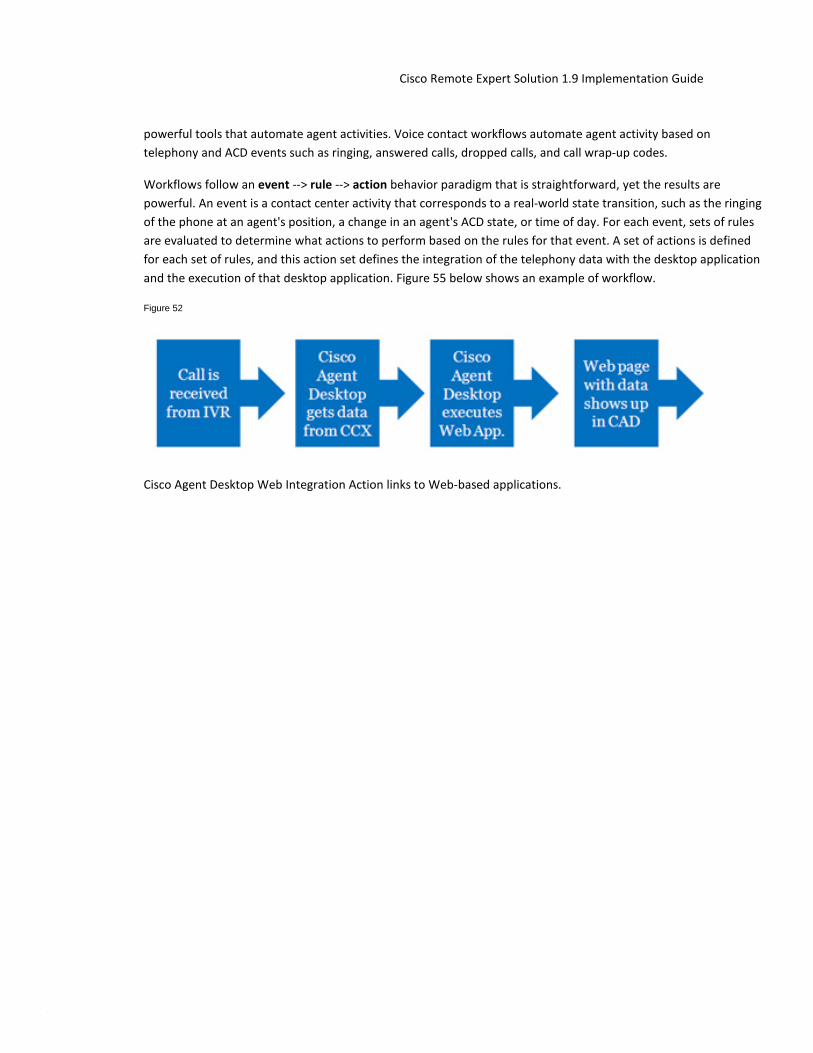
© 2014 Cisco and/or its affiliates. All rights reserved. This document is Cisco Public Information. Page 92
Cisco Remote Expert Solution 1.9 Implementation Guide
powerful tools that automate agent activities. Voice contact workflows automate agent activity based on telephony and ACD events such as ringing, answered calls, dropped calls, and call wrap-up codes.
Workflows follow an event --> rule --> action behavior paradigm that is straightforward, yet the results are powerful. An event is a contact center activity that corresponds to a real-world state transition, such as the ringing of the phone at an agent's position, a change in an agent's ACD state, or time of day. For each event, sets of rules are evaluated to determine what actions to perform based on the rules for that event. A set of actions is defined for each set of rules, and this action set defines the integration of the telephony data with the desktop application and the execution of that desktop application. Figure 55 below shows an example of workflow.
Figure 52
Cisco Agent Desktop Web Integration Action links to Web-based applications.
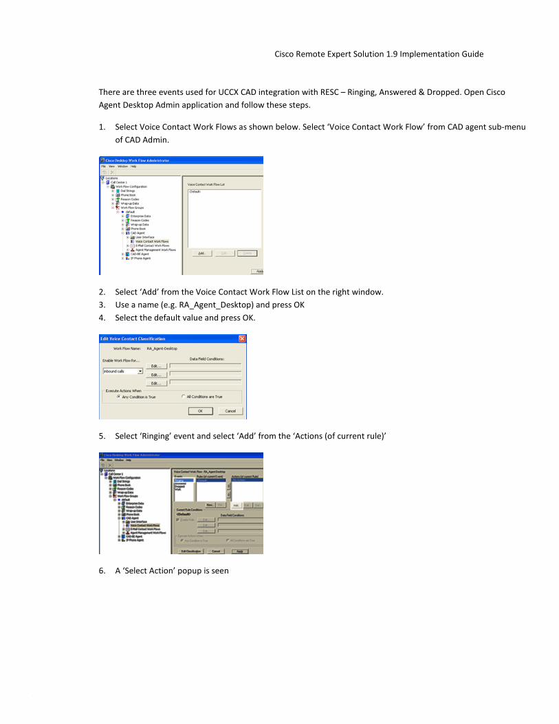
© 2014 Cisco and/or its affiliates. All rights reserved. This document is Cisco Public Information. Page 93
Cisco Remote Expert Solution 1.9 Implementation Guide
There are three events used for UCCX CAD integration with RESC – Ringing, Answered & Dropped. Open Cisco Agent Desktop Admin application and follow these steps.
1. Select Voice Contact Work Flows as shown below. Select ‘Voice Contact Work Flow’ from CAD agent sub-menu of CAD Admin.
2. Select ‘Add’ from the Voice Contact Work Flow List on the right window. 3. Use a name (e.g. RA_Agent_Desktop) and press OK 4. Select the default value and press OK.
5. Select ‘Ringing’ event and select ‘Add’ from the ‘Actions (of current rule)’
6. A ‘Select Action’ popup is seen

© 2014 Cisco and/or its affiliates. All rights reserved. This document is Cisco Public Information. Page 94
Cisco Remote Expert Solution 1.9 Implementation Guide
7. Now add the seven actions from the table listed below, into the ‘Select Action’ popup.
# Field Value 1. Action Type HTTP Action
Action Name Ringing
Protocol http
Method GET
Host REM_IP
Port 80
Path read/html/kiosk.jsp
Request Data
Value Name agent
Value Type Datafield
Value [Agent_ID]
Value Name calling
Value Type Datafield
Value Calling#
2. Action Type HTTP Action
Action Name Answered
Protocol http
Method GET
Host REM_IP

© 2014 Cisco and/or its affiliates. All rights reserved. This document is Cisco Public Information. Page 95
Cisco Remote Expert Solution 1.9 Implementation Guide
# Field Value Port 80
Path read/html/kiosk.jsp
Request Data
Value Name agent
Value Type Datafield
Value [Agent_ID]
3. Action Type HTTP Action
Action Name disconnect
Protocol http
Method GET
Host REM_IP
Port 80
Path read/html/common.jsp
Request Data
Value Name agent
Value Type Datafield
Value [Agent_ID]
Value Name request
Value Type UserDefined
Value disconnected
4. Action Type Launch External Application
Action Name DCInvoke
Application ..CSI\DirectConnect\bin\DirectConnect\DirectConnect.exe
Arguments [AGENT_ID]
5. Action Type Launch External Application

© 2014 Cisco and/or its affiliates. All rights reserved. This document is Cisco Public Information. Page 96
Cisco Remote Expert Solution 1.9 Implementation Guide
# Field Value Action Name DCExit
Application ..CSI\DirectConnect\bin\DirectConnect\DirectConnectClose.exe
Arguments None
6. Action Type HTTP Action
Action Name Not Ready
Protocol http
Method GET
Host REM_IP
Port 80
Path read/html/common.jsp
Request Data
Value Name agent
Value Type Datafield
Value [Agent_ID]
Value Name state
Value Type UserDefined
Value 1
7. Action Type HTTP Action
Action Name Ready
Protocol http
Method GET
Host REM_IP
Port 80
Path read/html/common.jsp
Request Data

© 2014 Cisco and/or its affiliates. All rights reserved. This document is Cisco Public Information. Page 97
Cisco Remote Expert Solution 1.9 Implementation Guide
# Field Value Value Name agent
Value Type Datafield
Value [Agent_ID]
Value Name state
Value Type UserDefined
Value 0
8. Associate the Events to the actions as seen in the table below. In order to associate an event, select the even from the left Events panel and then select the relevant action from the right Actions panel (while the specific event is still selected).
Table 4
Event Action
Ringing DCInvoke, Ringing
Answered Answered
Dropped DCExit Disconnect
Note Please note that the path field is case sensitive ‘read/html/kiosk.jsp’. Change the IP address of the host to the actual IP address of the RESC Virtual Machine, which is hosting the Kiosk App.
9. Apply and save the new changes and exit from this workflow. 10. Navigate to the Agent Management Work Flows 11. Click on Ready under Events in the left window panel and add the Ready action in the right panel. 12. Click on Not Ready event in the left window panel and add the Not Ready action in the right panel. 13. Apply and save the changes.
When agent login to their respective Cisco Agent Desktop (CAD), they will inherit the new rule. For example, after this new rule is applied, when the expert receives ‘Ringing’ on their phone, it will bring up an integrated browser based Agent Application window within the CAD as shown below.

© 2014 Cisco and/or its affiliates. All rights reserved. This document is Cisco Public Information. Page 98
Cisco Remote Expert Solution 1.9 Implementation Guide
Figure 53
7.5.1 Component Checkpoint
• Use Admin App “personnel” function to verify configured agents show up properly • Verify agents can log into CAD and see the READ populated.

© 2014 Cisco and/or its affiliates. All rights reserved. This document is Cisco Public Information. Page 99
Cisco Remote Expert Solution 1.9 Implementation Guide
8 UCCE/CVP Based Video In Queue and Video on Hold Configuration
In a video contact center or help desk scenario, when a customer wants to engage an agent/expert for help he can either use Immersive, Kiosk or Mobile options. During the initial phase of the video call, the customer is presented with an optional Video In Queue while he waits for next agent/expert to become available. Remote Expert Immersive and Kiosk support both REM based and UCCE based Video In Queue options. Remote Expert mobile only supports the UCCE based Video In Queue option.
When a customer clicks on the touchscreen kiosk or dial a predefined or time based HTTP URL in case of Mobile scenario, eventually it all maps to a pilot DN. This pilot DN is routed inside the UCCE system from CUCM where there is a corresponding UCCE routing script is running that is triggered based on this incoming DN.
This section provides details on configuring Video In Queue for Remote Expert Immersive, Kisok and Mobile channels which are mandatory for Mobile channel. The configuration steps provided in the sections above are mandatory for configuring UCCE/CVP based contact center and provide a baseline or foundation for the Video based contact center and specifically UCCE/CVP based Video in Queue configuration
Tech Tip: UCCE/CVP based Video In Queue (ViQ) configuration is needed for Remote Expert (RE) Mobile channel but optional for Immersive and Kiosk channels as a REM based ViQ can provide the similar functionality. Also note that in this document ViQ is used interchangeably with Video on Hold (VOH) because VOH can also be configured similarly the way ViQ is configured using UCCE routing script, Call Studio VXML script, VXML Gateway and Cisco MediaSense.
8.1 UCCE Routing Script Configuration This part assumes that all necessary configurations have already been done in CUCM to receive call either from Kiosk and Immersive touchscreens or from a Mobile device. For Kiosk and Immersive channels it is about configuring a SIP trunk in CUCM that will point to CVP. There is no configuration required for CVP to route this pilot DN to UCCE. CVP will route all calls it receives directly to UCCE for call routing or for further treatment.
For Mobile channel, the call is first routed to Expressway-E from where it enters into the enterprise and goes to Expressway-C. Expressway-C acts as a proxy at that point and forwards the call to Jabber Guest server. Jabber Guest translates the call from HTTP to SIP and route it to CUCM. From CUCM it routes to CVP via a SIP trunk. Details of this call flow and configuration are discussed in the next chapter.
When the call reaches UCCE, it will be matched by a UCCE routing script.
8.1.1 ICM AW Configuration
The call script is defined on the ICM AW (Admin Workstation) host.
8.1.2 UCCE Call Routing Script
The main UCCE call routing script is configured to run an external UCCE micro app (called invoke_vxml_app in the following pictures), at the very beginning of the call. This micro app instructs the VXML Server to execute a Call

© 2014 Cisco and/or its affiliates. All rights reserved. This document is Cisco Public Information. Page 100
Cisco Remote Expert Solution 1.9 Implementation Guide
Studio script. The name of the Call Studio script is defined as “ViQ_Sys1_70000”, which is running on the VXML server. The VXML-Server sends the call to VXML-Gateway for Video in Queue.
Figure 54
The Run Ext. Script node is defined as follows.

© 2014 Cisco and/or its affiliates. All rights reserved. This document is Cisco Public Information. Page 101
Cisco Remote Expert Solution 1.9 Implementation Guide
Figure 55
The Set Properties node sets the variable: user.microapp.ToExtVXML[] to equal the name of the VXML application. In this example, the variable is ViQ_Sys1_70000.
Figure 56
The actual VXML application is developed using Call Studio which is discussed in the next section.
8.2 Call Studio Configuration The VXML application is defined as follows.

© 2014 Cisco and/or its affiliates. All rights reserved. This document is Cisco Public Information. Page 102
Cisco Remote Expert Solution 1.9 Implementation Guide
Figure 57
The VideoConnect_01 node contains a DN that is used to route to the Cisco MediaSense server and to select a given video on the Cisco MediaSense server as shown. In this particular example the DN is set to 80000.
Figure 58
This VXML application is saved as a .zip file on the Call Studio host. In our example it is saved as ViQ.zip.

© 2014 Cisco and/or its affiliates. All rights reserved. This document is Cisco Public Information. Page 103
Cisco Remote Expert Solution 1.9 Implementation Guide
8.3 CVP Configuration
The VXML application must be deployed to all CVP VXML Servers. This is done by transferring the Call Studio generated .zip file, ViQ.zip in our case, that contains the VXML application to each CVP VXML server.
Tech Tip: Instead of moving manually and deploy on the VXML Server, it can also be done directly from the Call Studio GUI if the Call Studio is launched and the application is deployed from within the VXML server.
8.4 VXML Gateway Configuration CVP, when it executes the Run External Script node, sends a SIP INVITE to the VXML gateway using the DN defined in the VXML application’s VideoConnect_01 node. The VXML gateway contains a dial-peer that routes this SIP INVITE to the Cisco MediaSense server.
Tech Tip: CUBE (Cisco Unified Border Element) license is required since there are two SIP legs (incoming from VXML Server and outgoing towards Cisco MediaSense) terminating on the VXML gateway for the same call.
A basic IOS configuration for the VXML gateway is shown below:
voice service voip allow-connections sip to sip fax protocol t38 version 0 ls-redundancy 0 hs-redundancy 0 fallback none sip header-passing midcall-signaling block

© 2014 Cisco and/or its affiliates. All rights reserved. This document is Cisco Public Information. Page 104
Cisco Remote Expert Solution 1.9 Implementation Guide
application
service cvp_videoconnect flash:cvp_videoconnect.tcl dial-peer voice 80000 voip destination-pattern 8000T video codec h264 session protocol sipv2 ! 10.2.132.26 is the IP address of the MediaSense server session target ipv4:10.2.132.26 voice-class sip midcall-signaling block dtmf-relay rtp-nte codec g711ulaw no vad !
8.5 Cisco MediaSense Configuration Cisco MediaSense is configured to play a video based on the incoming DN. In our example, the DN is 80000. Cisco MediaSense will play the Cisco Sample Video once.

© 2014 Cisco and/or its affiliates. All rights reserved. This document is Cisco Public Information. Page 105
Cisco Remote Expert Solution 1.9 Implementation Guide
9 Jabber Guest and Expressway Configuration For Mobile Access
Cisco Jabber Guest is a consumer-to-business (C2B) solution that extends the reach of Cisco's enterprise telephony to people outside of a corporate firewall. Cisco Jabber Guest provides these people with the ability to use existing Unified Communications assets to communicate with your enterprise.
Before deploying a Cisco Jabber Guest server, you must have Cisco Expressway-E and Cisco Expressway-C. Without Cisco Expressway-C and Cisco Expressway-E, you will be limited to clients that can directly access the network on which the Cisco Jabber Guest server is homed.
This document assumes a thorough understanding of Cisco Expressway architecture for remote access. The following are some of the important concepts to understand before implementation is started.
9.1 Cisco Expressway-C and Cisco Expressway-E Cisco Jabber Guest can be deployed in combination with Cisco Expressway-E and Cisco Expressway-C or alternatively in combination with Cisco VCS-E and VCS-C. But deploying Cisco Expressway-E with VCS-C or VCS-E with Expressway-C is not a supported configuration. For details and difference between the two, refer to Cisco Unified Communications Mobile and Remote Access via Cisco Expressway Deployment Guide
9.2 Reverse Proxy Server The Cisco Expressway-E and Cisco Expressway-C can be used to tunnel HTTP from the Cisco Jabber Guest client to the Cisco Jabber Guest server. However, if a third-party reverse proxy is used, it needs be configured to proxy only the following URL types:
• /call • /jabber • /jc
9.3 Remote Expert Mobile Supported Devices Cisco Jabber Guest for iOS is supported on iOS 7.0 or later. The following iOS mobile devices are supported:
• iPad 4 • iPad 3 • iPad 2 • iPad Air • iPad mini • iPad mini with Retina display • iPhone 5s • iPhone 5c • iPhone 5 • iPhone 4s
The following Operating Systems are supported on Mobile/Desktop PC and Mac devices:

© 2014 Cisco and/or its affiliates. All rights reserved. This document is Cisco Public Information. Page 106
Cisco Remote Expert Solution 1.9 Implementation Guide
• Windows 7 • Windows 8 Desktop Version • MAC OS
The following browsers are supported on Mobile/Desktop PC and Mac devices:
• Mozilla Firefox 10 or later • Google Chrome 18 or later • Apple Safari 5 or later • Microsoft Internet Explorer 8 or later (32-bit only)
Windows 8 Metro version and Android devices are not supported with Remote Expert 1.9 release.
9.4 Call Links A Cisco Jabber Guest call link allows anyone to click-to-call an endpoint in the enterprise without creating an account, setting a password, or otherwise authenticating. The Cisco Jabber Guest web client launches when a link is clicked. This process greatly simplifies how a user places a call; they simply click on the provided link. This process allows the user to easily place a video call to the destination associated with the link.
The Cisco Jabber Guest server checks to see if the link exists in the database when a call is placed using it. The following operational parameters for the call are taken from the database if the link exists:
• Destination endpoint • Caller ID • Called ID • Time
The server checks the Allow Adhoc Links setting if the link is not listed in the database. If ad hoc links are enabled, the server sends the call to Cisco Expressway or Cisco Unified Communications Manager using the string to the right of /call/ as the route string. If the setting is disabled, the call is not routed unless the link exists in the database. Ad hoc links are enabled from Cisco Jabber Guest Administration.
9.5 Best Practices For Creating Call Links When you create a click-to-call link on a Cisco Jabber Guest server that is a member of a cluster, you must allow a small amount of time before that link is replicated on all servers in the cluster. The amount of time required for replication will vary depending on factors such as the network connection speed between the servers. Complete replication can occur within a second or may take several seconds.
9.6 Infrastructure Requirements You cannot use the same Cisco Expressway-C and Cisco Expressway-E pair or cluster for both Cisco Jabber Guest and Expressway for Mobile and Remote Access.
9.7 Jabber Guest Call Flow The Jabber Guest client residing in the Internet uses HTTPS to connect to the Jabber Guest server. The Jabber Guest server then places a SIP call within the enterprise on behalf of the Jabber Guest client. For Remote Expert, the Jabber Guest server places a call into a UCCE deployment. Refer to Figure 62.

© 2014 Cisco and/or its affiliates. All rights reserved. This document is Cisco Public Information. Page 107
Cisco Remote Expert Solution 1.9 Implementation Guide
Figure 59
The VCS-E server serves as a reverse proxy for the Jabber Guest client and Jabber Guest server. The VCS-E forwards HTTPS requests from the Jabber Guest client to the Jabber Guest server as shown in Figure 9.1. At the Jabber Guest client the URL of the VCS-E is used. For example consider
http://re-sys1-vcse1.lab.local:9443/call/70000
where
re-sys1-vcse1.lab.local - is the hostname of the VCS-E 70000 - is the UCCE Pilot DN

© 2014 Cisco and/or its affiliates. All rights reserved. This document is Cisco Public Information. Page 108
Cisco Remote Expert Solution 1.9 Implementation Guide
Figure 60
The 9443 port is used for reverse proxy requests. All HTTPS request received on port 9443 are reversed proxied. The reverse proxy port of 9443 is hard coded and is not configurable on the VCS-E.
It is important to mention here that in almost all production deployments, HTTP and HTTPS traffic from Cisco Jabber Guest clients in the Internet is sent to ports 80 and 443 TCP respectively. Therefore the firewall between the Cisco Expressway-E and the public Internet must translate destination port 80 to 9980 and destination port 443 to 9443 for all TCP traffic that targets the Cisco Expressway-E address. The Cisco Expressway-E will redirect HTTP requests on port 9980 to HTTPS on 9443. For more information refer to Install and Deploy Cisco Jabber Guest.
TCP port 80/443 are the standard HTTP/S administration interfaces on the Expressway. If the Cisco Expressway-E is administered from systems located in the Internet, then the firewall translation must also distinguish by source address and must not translate the destination port of traffic arriving from those management systems.
You also need to ensure that appropriate DNS records exist so that the Cisco Jabber Guest client can reach the Cisco Expressway-E. The FQDN of the Cisco Expressway-E in DNS must include the Cisco Jabber Guest domain. The Cisco Jabber Guest domain is the domain that is configured on the Cisco Expressway-C.
The proxy to Jabber Guest is controlled by using an option under “Unified Communication Mode” called “Jabber Guest services” in Expressway-E (or VCS-E) and Expressway-C (or VCS-C) servers. The proxy to Jabber Guest feature is configured under the Configuration --> Unified Communications --> Configuration as shown below. On the VSC-E, set the Unified Communications Mode to Jabber Guest services.

© 2014 Cisco and/or its affiliates. All rights reserved. This document is Cisco Public Information. Page 109
Cisco Remote Expert Solution 1.9 Implementation Guide
Figure 61 VCS-E Unified Communications Configuration
Likewise on the VCS-C set the Unified Communications mode to Jabber Guest services.
Figure 62 VCS-C Unified Communications Configuration
Additionally, on the VCS-C configure the Jabber guest server hostname or IP address.

© 2014 Cisco and/or its affiliates. All rights reserved. This document is Cisco Public Information. Page 110
Cisco Remote Expert Solution 1.9 Implementation Guide
Figure 63 VCS-C Jabber Guest Server Configuration
As shown above re-sys1-jabberg1.lab.local is the Jabber Guest server for the lab.local domain. The “Jabber Guest servers” configuration determines which Jabber Guest server should receive the HTTPS request. The above configuration instructs the VSC-C to send all Jabber Guest HTTPS request for domain lab.local to re-sys1-jabberg1.lab.local.
The domain is also configured on the VCS-C. Jabber Guest services are enabled at the domain configuration web page as shown below.
Figure 64 VCS-C Domain Configuration

© 2014 Cisco and/or its affiliates. All rights reserved. This document is Cisco Public Information. Page 111
Cisco Remote Expert Solution 1.9 Implementation Guide
9.7.1 Communication between VCS-E and VCS-C
The VCS-E and VCS-C are designed to traverse firewalls. The VCS-E located in the DMZ, acts as a traversal server and the VCS-C, located within the data center, acts as a traversal client. The VCS-C is the client and originates connections to the VCS-E. This is done so that connections through the firewall are initialized from within the enterprise network.
Figure 65 VCS Traversal Client and Traversal Server
The connection between VCS-E and VSC-C is setup by creating a Traversal server zone on the VCS-E as shown below.
Figure 66 VCS-E Traversal Zone
A Traversal client zone on the VCS-C as shown below.

© 2014 Cisco and/or its affiliates. All rights reserved. This document is Cisco Public Information. Page 112
Cisco Remote Expert Solution 1.9 Implementation Guide
Figure 67 VCS-C Traversal Zone
Once these traversal zones are created the VCS-E and VCS-C can communicate through the firewall.
The traversal zones on VCS-E and VSC-C do not mention HTTP or HTTPS. However, the traversal zones do have a SIP configuration section. This SIP configuration section is leveraged by VCS-E and VCS-C to perform the reverse proxy. The following figure illustrates the SIP configuration section of the VSC-E server traversal zone configuration.

© 2014 Cisco and/or its affiliates. All rights reserved. This document is Cisco Public Information. Page 113
Cisco Remote Expert Solution 1.9 Implementation Guide
Figure 68 VCS-E Server Traversal Zone Configuration
The traversal zone configuration on the VCS-C server is shown below.

© 2014 Cisco and/or its affiliates. All rights reserved. This document is Cisco Public Information. Page 114
Cisco Remote Expert Solution 1.9 Implementation Guide
Figure 69
Figure 70 VCS-C Traversal Zone Configuration
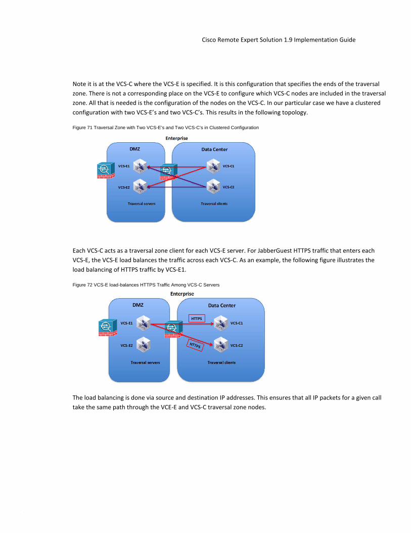
© 2014 Cisco and/or its affiliates. All rights reserved. This document is Cisco Public Information. Page 115
Cisco Remote Expert Solution 1.9 Implementation Guide
Note it is at the VCS-C where the VCS-E is specified. It is this configuration that specifies the ends of the traversal zone. There is not a corresponding place on the VCS-E to configure which VCS-C nodes are included in the traversal zone. All that is needed is the configuration of the nodes on the VCS-C. In our particular case we have a clustered configuration with two VCS-E’s and two VCS-C’s. This results in the following topology.
Figure 71 Traversal Zone with Two VCS-E’s and Two VCS-C’s in Clustered Configuration
Each VCS-C acts as a traversal zone client for each VCS-E server. For JabberGuest HTTPS traffic that enters each VCS-E, the VCS-E load balances the traffic across each VCS-C. As an example, the following figure illustrates the load balancing of HTTPS traffic by VCS-E1.
Figure 72 VCS-E load-balances HTTPS Traffic Among VCS-C Servers
The load balancing is done via source and destination IP addresses. This ensures that all IP packets for a given call take the same path through the VCE-E and VCS-C traversal zone nodes.

© 2014 Cisco and/or its affiliates. All rights reserved. This document is Cisco Public Information. Page 116
Cisco Remote Expert Solution 1.9 Implementation Guide
The VCS-E needs a search rule that routes calls to the VCS-C. In our example this is accomplished with a search rule that matches any SIP URI pattern and routes the call, the HTTPS request, to the traversal zone and to the VCS-C.
Figure 73 VCS-E Search Rule for the Traversal Zone
The Jabber guest client’s HTTPS request contains a VCS-E URL using port 9443 (9443 is used for reverse proxy request), VCS-E forwards the HTTPS request to the VCS-C (using the information configured in the Traversal server zone). VCS-C then forwards the request to the Jabber Guest server. VCS-C forwards the request to the Jabber Gest server configured in its Jabber Guest server’s page (See Figure 66) for the domain specified in the URL requested by the Jabber guest client. In our example the HTTPS request from the Jabber Guest client is as follows:
https://re-sys1-vcse1.lab.local:9443/call/70000
The request contains the domain lab.local and is directed by the VCS-C to “re-sys1-jabberg1.lab.local”
Once the Jabber Guest server receives the HTTPS request it will initiate a SIP call to the VCS-C. Continuing with our example the Jabber Guest server will basically turn the following HTTP request into a SIP invite:
HTTPS Request: https://re-sys1-vcse1.lab.local:9443/call/70000

© 2014 Cisco and/or its affiliates. All rights reserved. This document is Cisco Public Information. Page 117
Cisco Remote Expert Solution 1.9 Implementation Guide
SIP Invite: sip:[email protected]
In our example, 10.0.133.190 is the IP address of the Expressway-C.
Figure 74 JabberG Server Initiates Call to VSC-C
The Jabber Guest server routes the SIP call using the information from Settings--> Call Control and Media. Select Route calls using Cisco Expressway and select Send SIP Traffic to Expressway-C server that proxied the HTTP request from Jabber Guest client. Configure the data for the VSC-C or as it is denoted on the Jabber Guest GUI: Expressway-C. The following figure illustrates the configuration.

© 2014 Cisco and/or its affiliates. All rights reserved. This document is Cisco Public Information. Page 118
Cisco Remote Expert Solution 1.9 Implementation Guide
Figure 75
Figure 76 JabberG Server Expressway-C Configuration
In order for the VCS-C to accept the incoming SIP message from the Jabber Guest server, a SIP zone for the Jabber Guest server must be configured on the VCS-C. See the following figure.

© 2014 Cisco and/or its affiliates. All rights reserved. This document is Cisco Public Information. Page 119
Cisco Remote Expert Solution 1.9 Implementation Guide
Figure 77 VCS-C Jabber Guest Server Configuration
Figure 78
The VSC-C routes the call to the enterprise CUCM (Cisco Unfied Communications Manager). To facilitate this routing, a SIP communication channel is configured between the VCS-C and the CUCM. On the VCS-C, a neighbor zone for the CUCM (Cisco Unified Communications Manager) is configured under Configuration --> Zones.

© 2014 Cisco and/or its affiliates. All rights reserved. This document is Cisco Public Information. Page 120
Cisco Remote Expert Solution 1.9 Implementation Guide
Figure 79
Figure 80

© 2014 Cisco and/or its affiliates. All rights reserved. This document is Cisco Public Information. Page 121
Cisco Remote Expert Solution 1.9 Implementation Guide
Figure 81 VCS-C CUCM Zone
Likewise, on CUCM a SIP trunk that points to the VSC-C is configured under Device --> Trunk.
Figure 82
Figure 83
Figure 84. CUCM VCS-C SIP Trunk Configuration.
The VSC-C is configured with a Transform that transforms the SIP request with an IP address to a SIP request with a fully qualified domain name as shown below:

© 2014 Cisco and/or its affiliates. All rights reserved. This document is Cisco Public Information. Page 122
Cisco Remote Expert Solution 1.9 Implementation Guide
INVITE sip:[email protected]
INVITE sip:[email protected]
Figure 85
The VCS-C is configured with a search rule under Configuration --> Dial Plans --> Search Rules that replaces the VSC-C SIP URI with a CUCM SIP URI and forwards the INVITE to the CUCM zone.

© 2014 Cisco and/or its affiliates. All rights reserved. This document is Cisco Public Information. Page 123
Cisco Remote Expert Solution 1.9 Implementation Guide
Figure 86 VCS-C Search Rule Configuration
This search rule transforms the SIP request for the VCS-C to a SIP request for CUCM, as shown below:
INVITE sip:[email protected]
INVITE sip:[email protected]
The SIP request is forwarded to the CUCM defined in the RE-SYS1-CUCM zone shown previously.

© 2014 Cisco and/or its affiliates. All rights reserved. This document is Cisco Public Information. Page 124
Cisco Remote Expert Solution 1.9 Implementation Guide
Figure 87 VCS-C Forwards INVITE from JabberG Server to CUCM
The CUCM must be configured with a Cluster Fully Qualified Domain Name that matches the INVITE sent by the VCS-C. Or in other words the VSC-C should send an INVITE to the CUCM that matches the Cluster Fully Qualified Domain Name. The Cluster Fully Qualified Domain Name is configured from the System-->Enterprise Parameters Configuration page as shown below.
Figure 88 CUCM Domain Configuration

© 2014 Cisco and/or its affiliates. All rights reserved. This document is Cisco Public Information. Page 125
Cisco Remote Expert Solution 1.9 Implementation Guide
9.8 Network Diagram
The configuration examples in this document are based on the following network topology.

© 2014 Cisco and/or its affiliates. All rights reserved. This document is Cisco Public Information. Page 126
Cisco Remote Expert Solution 1.9 Implementation Guide
Figure 89 Example Network Reference Diagram

© 2014 Cisco and/or its affiliates. All rights reserved. This document is Cisco Public Information. Page 127
Cisco Remote Expert Solution 1.9 Implementation Guide
10 Advanced Features
The previous chapters presented a step-by-step guide to deploying the “basic” features and functionality of the Cisco Remote Expert Solution. In addition to these basic features, the solution supports a number of advanced features, including:
• Recording of the audio portion of the Remote Expert session • Supervised transfer of a Remote Expert session between Remote Expert agents • Supervised conferencing between the Customer Pod and up to two Remote Expert Agents • Specialized Customer Pod peripheral integration
Information on the basic deployment of these features is found in the remaining chapters of this document. However, implementing certain features requires prerequisites, including:
• Integrating Cisco Unified Border Element (CUBE) with the Cisco Remote Expert Solution • Configuring Cisco MediaSense audio recording for the Cisco Remote Expert Solution • Integrating the Cisco Media Conferencing Unit (MCU) 4501 with the Remote Expert Solution.
These prerequisites are covered in the following sections.
10.1 Cisco MediaSense Cisco MediaSense records conversations on the network rather than on a device. This simplifies the architecture, lowers costs, provides optimum scalability, and facilitates use by analytics applications from Cisco technology partners.
In the Remote Expert solution, the Cisco MediaSense server is positioned to begin recording when the Customer is removed from the queue and connected to an Expert or a Contact Center Agent. This is done by CUBE initially forking the audio portion of the to the Cisco MediaSense server for recording purpose.
We will cover the steps to setup Cisco MediaSense for basic audio recording of the Remote Expert call flow.
10.1.1 CUCM Configuration
The Cisco MediaSense server needs to communicate with the CUCM for passing on the API and status information mainly useful for reporting.

© 2014 Cisco and/or its affiliates. All rights reserved. This document is Cisco Public Information. Page 128
Cisco Remote Expert Solution 1.9 Implementation Guide
Steps::
1. Login to Cisco MediaSense GUI using an administrator user created during installation. 2. Proceed to the Cisco MediaSense Administration page. 3. Select Administration --> Unified CM configuration. 4. Select the CUCM server from the Available AXL Service Providers list. 5. Enter the API user created on the CUCM for communicating with Cisco MediaSense. 6. Select the CUCM server from the Available Call Control Service Providers list. 7. Click Save.
Figure 90
10.1.2 Cisco MediaSense API User Configuration
Configure a Cisco MediaSense API user to playback audio recording from the server. This user will also be configured on the REM to enable GUI based playback options.
Steps::
1. Login to Cisco MediaSense server as an administrator user. 2. Proceed to Administration --> MediaSense API User Configuration 3. Click on Add New 4. Enter details for a user with permissions to invoke playback. 5. Click Save.
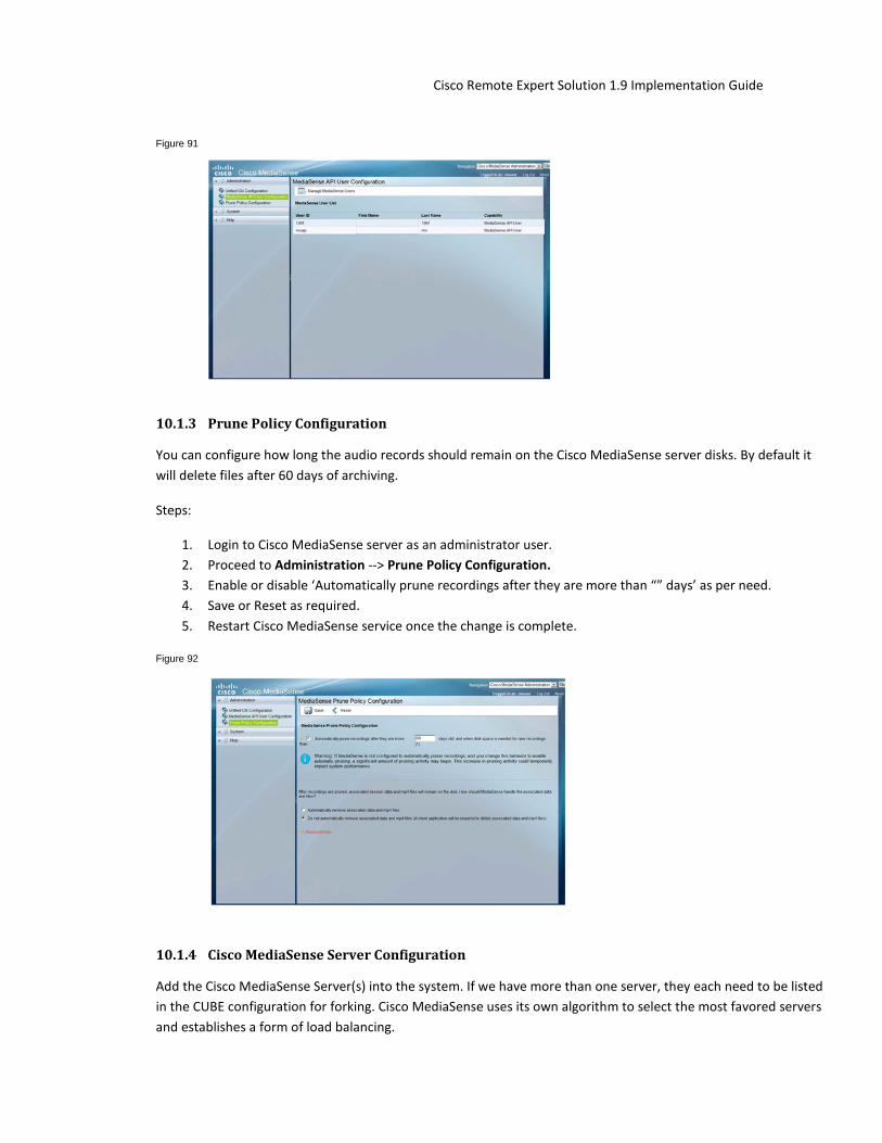
© 2014 Cisco and/or its affiliates. All rights reserved. This document is Cisco Public Information. Page 129
Cisco Remote Expert Solution 1.9 Implementation Guide
Figure 91
10.1.3 Prune Policy Configuration
You can configure how long the audio records should remain on the Cisco MediaSense server disks. By default it will delete files after 60 days of archiving.
Steps:
1. Login to Cisco MediaSense server as an administrator user. 2. Proceed to Administration --> Prune Policy Configuration. 3. Enable or disable ‘Automatically prune recordings after they are more than “” days’ as per need. 4. Save or Reset as required. 5. Restart Cisco MediaSense service once the change is complete.
Figure 92
10.1.4 Cisco MediaSense Server Configuration
Add the Cisco MediaSense Server(s) into the system. If we have more than one server, they each need to be listed in the CUBE configuration for forking. Cisco MediaSense uses its own algorithm to select the most favored servers and establishes a form of load balancing.
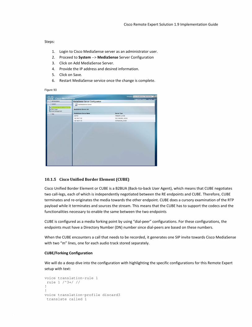
© 2014 Cisco and/or its affiliates. All rights reserved. This document is Cisco Public Information. Page 130
Cisco Remote Expert Solution 1.9 Implementation Guide
Steps:
1. Login to Cisco MediaSense server as an administrator user. 2. Proceed to System --> MediaSense Server Configuration 3. Click on Add MediaSense Server. 4. Provide the IP address and desired information. 5. Click on Save. 6. Restart MediaSense service once the change is complete.
Figure 93
10.1.5 Cisco Unified Border Element (CUBE)
Cisco Unified Border Element or CUBE is a B2BUA (Back-to-back User Agent), which means that CUBE negotiates two call-legs, each of which is independently negotiated between the RE endpoints and CUBE. Therefore, CUBE terminates and re-originates the media towards the other endpoint. CUBE does a cursory examination of the RTP payload while it terminates and sources the stream. This means that the CUBE has to support the codecs and the functionalities necessary to enable the same between the two endpoints
CUBE is configured as a media forking point by using “dial-peer” configurations. For these configurations, the endpoints must have a Directory Number (DN) number since dial-peers are based on these numbers.
When the CUBE encounters a call that needs to be recorded, it generates one SIP invite towards Cisco MediaSense with two “m” lines, one for each audio track stored separately.
CUBE/Forking Configuration
We will do a deep dive into the configuration with highlighting the specific configurations for this Remote Expert setup with text:
voice translation-rule 1 rule 1 /^3+/ // ! ! voice translation-profile discard3 translate called 1

© 2014 Cisco and/or its affiliates. All rights reserved. This document is Cisco Public Information. Page 131
Cisco Remote Expert Solution 1.9 Implementation Guide
! ! ! !--- create MediaSense class for forking media class 3 recorder parameter media-recording 3000 3001 3002 ! ! interface Embedded-Service-Engine0/0 no ip address shutdown ! . . . . . ! ip http server ! ! mgcp behavior rsip-range tgcp-only mgcp behavior comedia-role none mgcp behavior comedia-check-media-src disable mgcp behavior comedia-sdp-force disable ! mgcp profile default ! ! !—-- Apply MediaSense media class to the incoming dial-peer dial-peer voice 1000 voip description inbound and forking rtp payload-type cisco-codec-fax-ack 110 rtp payload-type cisco-codec-video-h264 97 session protocol sipv2 incoming called-number 2... voice-class codec 1 offer-all voice-class sip asserted-id pai media-class 3 ! !—-- Send the call to CUCM to handle routing to the expert endpoint dial-peer voice 2000 voip description outbound destination-pattern 2... rtp payload-type cisco-codec-fax-ack 110 rtp payload-type cisco-codec-video-h264 97 session protocol sipv2 session target ipv4:192.168.71.40:5060 voice-class codec 1 offer-all ! !—-- Send call to MediaSense expansion dial-peer voice 3000 voip description MediaSense-expansion destination-pattern 3333 session protocol sipv2 session target ipv4:192.168.71.55 session transport tcp voice-class sip options-keepalive ! !—-- Send call to MediaSense primary dial-peer voice 3001 voip

© 2014 Cisco and/or its affiliates. All rights reserved. This document is Cisco Public Information. Page 132
Cisco Remote Expert Solution 1.9 Implementation Guide
description MediaSense-primary destination-pattern 3333 session protocol sipv2 session target ipv4:192.168.71.52 session transport tcp voice-class sip options-keepalive ! !—-- Send call to MediaSense secondary dial-peer voice 3002 voip description Mediasense-secondary destination-pattern 3333 session protocol sipv2 session target ipv4:192.168.71.92 session transport tcp voice-class sip options-keepalive ! ! ! gatekeeper shutdown ! !
10.1.6 Conferencing/Transfers
In the Cisco Remote Expert Solution, for conferencing call flows we use a Codian MCU 4610 registered to CUCM as the Video Conference Bridge.
MCU 4610 Configuration
Below, you will find quick steps to configure the Media Conferencing Unit for setting up the Video Conferencing feature in the Cisco Remote Expert Solution.
Steps:
1. Login to the MCU as Administrator user. 2. Ensure licenses are uploaded and the build version on the MCU is as required. 3. Proceed to Home --> Network --> PortA/B and configure the basic networking/reachability. 4. Ensure under Home --> Network --> Services, SIP is enabled and the port is 5060. 5. Check the settings under Home --> Settings --> Conferences has the desired configurations. 6. Under Home --> Settings --> SIP, make sure that SIP registrar type is Standard SIP 7. Select HD for the Home --> Settings --> Media Port’s Media Port Mode. 8. Save configuration and exit.
Once this is complete, we need to add this MCU as a Cisco Telepresence MCU in the CUCM Conference Bridge add page. Point the IP address in this configuration to the IP address of the MCU. Also provide HTTP credentials for the Conference Bridge configuration.
10.2 Specialized Customer Pod peripheral integration The Cisco Remote Expert Solution supports extensions allowing specialized peripherals to be installed at the Media Conferencing Unit for setting up Customer Pods and integrated with the Video Conferencing feature in the solution, including:

© 2014 Cisco and/or its affiliates. All rights reserved. This document is Cisco Public Information. Page 133
Cisco Remote Expert Solution 1.9 Implementation Guide
• Keypads • Magnetic Card Readers
For more information on specialized peripheral integration with the Cisco Remote Expert Solution, please refer to Chapters X-Y of the Deploying REM for the Cisco Remote Expert Solution 1.9 Guide.
Steps:
1. Login to the MCU as Administrator user. 2. Ensure licenses are uploaded and the build version on the MCU is as required. 3. Proceed to Home--> Network --> Port A/B and configure the basic networking/reachability. 4. Ensure under Home --> Network --> Services, SIP is enabled and the port is 5060. 5. Check the settings under Home --> Settings --> Conferences has the desired configurations. 6. Under Home --> Settings --> SIP, make sure that SIP registrar type is Standard SIP. 7. Select HD for the Home --> Settings --> Media Port’s Media Port Mode. 8. Save configuration and exit.
Once this is complete, we need to add this MCU as a Cisco Telepresence MCU in the CUCM Conference Bridge add page. Point the IP address in this configuration to the IP address of the MCU. Also provide HTTP credentials for the Conference Bridge configuration.
10.3 Custom Branding the Remote Expert Solution The default branding assets installed are sufficient for verifying basic system operation. Custom branding assets will need to be designed, developed, tested in conjunction with the solution and approved by the enterprise customer before the solution can be placed into actual trials or production.
Please refer to Chapters 2 and 3 of the Cisco Remote Expert Manager 1.9 Administration Guide for information on aspects of customizing the graphical user interface of the Cisco Remote Expert Solution and how to deploy these customizations.

© 2014 Cisco and/or its affiliates. All rights reserved. This document is Cisco Public Information. Page 134
Cisco Remote Expert Solution 1.9 Implementation Guide
11 References
Please refer to following supporting documents for more detailed information.
1. Cisco Remote Expert Manager Home Page 2. Cisco Remote Expert Manager 1.9 Installation Guide 3. Cisco Remote Expert Manager 1.9 Administration Guide 4. Cisco Remote Expert Manager 1.8 Agent Desktop User Guide
Cisco Remote Expert READ and eREAD User Guide 5. Cisco Remote Expert Manager 1.9 Troubleshooting & Serviceability Guide 6. Cisco Remote Expert Manager 1.9 Release Notes 7. Cisco Remote Expert Solution Validated Design Guide

© 2014 Cisco and/or its affiliates. All rights reserved. This document is Cisco Public Information. Page 135
Cisco Remote Expert Solution 1.9 Implementation Guide
12 Appendix A: As-Tested Configurations
12.1 CUBE Configuration
re-sys1-cube-left#show run version 15.4 service timestamps debug datetime msec localtime service timestamps log datetime msec no service password-encryption ! hostname re-sys1-cube-left ! boot-start-marker boot system flash c3900e-universalk9-mz.SPA.154-1.T1.bin boot-end-marker ! aqm-register-fnf ! no logging queue-limit logging buffered 50000000 no logging rate-limit no logging console no logging monitor enable secret 5 $1$tvcX$WlnYJW1WvOYmVm33Ltp370 enable password cisco_123 ! no aaa new-model clock timezone EST -5 0 ! !no ip domain lookup ip domain name lab.local ip name-server 10.0.128.250 ip name-server 10.0.128.251 ip cef no ipv6 cef ! multilink bundle-name authenticated ! voice-card 0 ! voice service voip no ip address trusted authenticate mode border-element allow-connections sip to sip fax protocol t38 version 0 ls-redundancy 0 hs-redundancy 0 fallback none sip asymmetric payload full ! voice class codec 3 codec preference 2 g711ulaw video codec h264 ! media profile recorder 1 media-recording 20 ! media class 1

© 2014 Cisco and/or its affiliates. All rights reserved. This document is Cisco Public Information. Page 136
Cisco Remote Expert Solution 1.9 Implementation Guide
recorder profile 1 ! license udi pid C3900-SPE250/K9 sn FOC16375Q0E ! ! username ADMIN privilege 15 secret 4 dwFj6nbgXWcG3oFqthkVuGgUrCGo24QryqelliIr8P2 ! redundancy ! interface GigabitEthernet0/0 ip address 10.2.132.102 255.255.255.0 duplex auto speed auto no mop enabled hold-queue 4096 in ! interface GigabitEthernet0/1 no ip address shutdown duplex auto speed auto ! interface GigabitEthernet0/2 no ip address shutdown duplex auto speed auto ! interface GigabitEthernet0/3 no ip address shutdown duplex auto speed auto ! ip forward-protocol nd ! no ip http server no ip http secure-server ! ip route 0.0.0.0 0.0.0.0 10.2.132.1 ! nls resp-timeout 1 cpd cr-id 1 ! snmp-server community public RO snmp-server enable traps vstack operation ! control-plane ! mgcp behavior rsip-range tgcp-only mgcp behavior comedia-role none mgcp behavior comedia-check-media-src disable mgcp behavior comedia-sdp-force disable ! mgcp profile default ! dial-peer voice 1 voip description Inbound Dial-peer for the call that needs to be recorded session protocol sipv2 session transport tcp incoming called-number .T voice-class codec 3 voice-class sip asserted-id pai

© 2014 Cisco and/or its affiliates. All rights reserved. This document is Cisco Public Information. Page 137
Cisco Remote Expert Solution 1.9 Implementation Guide
media-class 1 ! dial-peer voice 2 voip description Outbound Dial-peer for the call that needs to be recorded destination-pattern [12].T session protocol sipv2 session target ipv4:10.0.133.106:5060 session transport tcp voice-class codec 3 ! dial-peer voice 20 voip description Dial-peer pointing to MediaSense destination-pattern 10000 signaling forward none session protocol sipv2 session target ipv4:10.2.132.26:5060 session transport tcp voice-class sip options-keepalive ! gatekeeper shutdown ! line con 0 line aux 0 line vty 0 4 exec-timeout 0 0 privilege level 15 password cisco_123 login local transport input telnet ssh line vty 5 15 privilege level 15 password cisco_123 login local transport input telnet ssh ! scheduler allocate 20000 1000 ntp server 10.1.253.1 ! end re-sys1-cube-left# telnet> quit Connection closed. bash-3.2$ exit exit
12.2 VXML Configuration re-sys1-vxml-left#show run Building configuration... version 15.3 service timestamps debug datetime msec service timestamps log datetime msec no service password-encryption ! hostname re-sys1-vxml-left ! boot-start-marker boot system flash:c3900-universalk9-mz.SPA.153-2.T.bin boot-end-marker !

© 2014 Cisco and/or its affiliates. All rights reserved. This document is Cisco Public Information. Page 138
Cisco Remote Expert Solution 1.9 Implementation Guide
! card type command needed for slot/vwic-slot 1/1 enable password cisco_123 ! no aaa new-model no network-clock-participate slot 1 ! ip cef ! ip domain lookup source-interface GigabitEthernet0/0 ip domain name lab.local ip name-server 10.0.128.250 ip name-server 10.0.128.251 no ipv6 cef multilink bundle-name authenticated ! voice-card 0 ! voice-card 1 ! ! ! voice service voip no ip address trusted authenticate allow-connections sip to sip signaling forward unconditional fax protocol t38 version 0 ls-redundancy 0 hs-redundancy 0 fallback none sip rel1xx disable header-passing options-ping 60 ! voice class codec 1 codec preference 1 g711ulaw codec preference 2 g729r8 ! ivr prompt memory 15000 ivr asr-server rtsp://asr-en-us/recognizer ivr tts-server rtsp://tts-en-us/synthesizer ! application service new-call flash:bootstrap.vxml paramspace english language en paramspace english index 0 paramspace english location flash paramspace english prefix en ! service cvp-survivability flash:survivability.tcl paramspace english index 0 paramspace english language en paramspace english location flash paramspace english prefix en ! service CVPSelfService flash:CVPSelfServiceBootstrap.vxml ! service ringtone flash:ringtone.tcl paramspace english language en paramspace english index 0 paramspace english location flash paramspace english prefix en ! service cvperror flash:cvperror.tcl paramspace english index 0 paramspace english language en
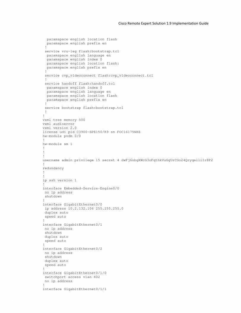
© 2014 Cisco and/or its affiliates. All rights reserved. This document is Cisco Public Information. Page 139
Cisco Remote Expert Solution 1.9 Implementation Guide
paramspace english location flash paramspace english prefix en ! service vru-leg flash:bootstrap.tcl paramspace english language en paramspace english index 0 paramspace english location flash: paramspace english prefix en ! service cvp_videoconnect flash:cvp_videoconnect.tcl ! service handoff flash:handoff.tcl paramspace english index 0 paramspace english language en paramspace english location flash paramspace english prefix en ! service bootstrap flash:bootstrap.tcl ! ! vxml tree memory 500 vxml audioerror vxml version 2.0 license udi pid C3900-SPE150/K9 sn FOC16175NHZ hw-module pvdm 0/0 ! hw-module sm 1 ! ! ! username admin privilege 15 secret 4 dwFj6nbgXWcG3oFqthkVuGgUrCGo24QryqelliIr8P2 ! redundancy ! ! ip ssh version 1 ! interface Embedded-Service-Engine0/0 no ip address shutdown ! interface GigabitEthernet0/0 ip address 10.2.132.106 255.255.255.0 duplex auto speed auto ! interface GigabitEthernet0/1 no ip address shutdown duplex auto speed auto ! interface GigabitEthernet0/2 no ip address shutdown duplex auto speed auto ! interface GigabitEthernet0/1/0 switchport access vlan 402 no ip address ! interface GigabitEthernet0/1/1

© 2014 Cisco and/or its affiliates. All rights reserved. This document is Cisco Public Information. Page 140
Cisco Remote Expert Solution 1.9 Implementation Guide
switchport access vlan 402 no ip address ! interface GigabitEthernet0/1/2 no ip address ! interface GigabitEthernet0/1/3 no ip address ! interface GigabitEthernet0/1/4 no ip address ! interface GigabitEthernet0/1/5 no ip address ! interface GigabitEthernet0/1/6 no ip address ! interface GigabitEthernet0/1/7 no ip address ! interface Vlan1 no ip address ! ip default-gateway 10.2.132.1 ip forward-protocol nd ! no ip http server no ip http secure-server ! ip route 0.0.0.0 0.0.0.0 10.2.132.1 ! nls resp-timeout 1 cpd cr-id 1 ! control-plane ! mgcp behavior rsip-range tgcp-only mgcp behavior comedia-role none mgcp behavior comedia-check-media-src disable mgcp behavior comedia-sdp-force disable ! mgcp profile default ! ! dial-peer voice 919191 voip description CVP SIP ringtone dial-peer service ringtone incoming called-number 9191T voice-class codec 1 voice-class sip rel1xx disable dtmf-relay rtp-nte h245-signal h245-alphanumeric no vad ! dial-peer voice 929292 voip description CVP SIP error dial-peer service cvperror incoming called-number 9292T voice-class codec 1 voice-class sip rel1xx disable dtmf-relay rtp-nte h245-signal h245-alphanumeric no vad !

© 2014 Cisco and/or its affiliates. All rights reserved. This document is Cisco Public Information. Page 141
Cisco Remote Expert Solution 1.9 Implementation Guide
dial-peer voice 9999 voip description Used for VRU leg service bootstrap incoming called-number 9999T voice-class codec 1 dtmf-relay rtp-nte h245-signal h245-alphanumeric no vad ! dial-peer voice 80000 voip destination-pattern 8000T video codec h264 session protocol sipv2 session target ipv4:10.2.132.26 voice-class sip midcall-signaling block dtmf-relay rtp-nte codec g711ulaw no vad ! ! gateway media-inactivity-criteria all timer receive-rtp 1200 ! sip-ua retry invite 2 retry bye 1 timers expires 60000 timers connect 1000 reason-header override ! ! ! gatekeeper shutdown ! ! ! line con 0 line aux 0 line 2 no activation-character no exec transport preferred none transport input all transport output pad telnet rlogin lapb-ta mop udptn v120 ssh stopbits 1 line vty 0 4 privilege level 15 password cisco_123 login local transport input telnet ssh line vty 5 15 privilege level 15 login local transport input telnet ssh ! scheduler allocate 20000 1000 ! end re-sys1-vxml-left#

© 2014 Cisco and/or its affiliates. All rights reserved. This document is Cisco Public Information. Page 142
Cisco Remote Expert Solution 1.9 Implementation Guide
Printed in USA 05/11