cisco collaborative care—language interpretation services
TRANSCRIPT

Cisco Collaborative Care—Language Interpretation Services Design and Implementation GuideOL-14269-01 July 24, 2007
Americas HeadquartersCisco Systems, Inc.170 West Tasman DriveSan Jose, CA 95134-1706 USAhttp://www.cisco.comTel: 408 526-4000
800 553-NETS (6387)Fax: 408 527-0883
Customer Order Number: Text Part Number: OL-14269-01

ALL DESIGNS, SPECIFICATIONS, STATEMENTS, INFORMATION, AND RECOMMENDATIONS (COLLECTIVELY, "DESIGNS") IN THIS MANUAL ARE PRESENTED "AS IS," WITH ALL FAULTS. CISCO AND ITS SUPPLIERS DISCLAIM ALL WARRANTIES, INCLUDING, WITHOUT LIMITATION, THE WARRANTY OF MERCHANTABILITY, FITNESS FOR A PARTICULAR PURPOSE AND NONINFRINGEMENT OR ARISING FROM A COURSE OF DEALING, USAGE, OR TRADE PRACTICE. IN NO EVENT SHALL CISCO OR ITS SUPPLIERS BE LIABLE FOR ANY INDIRECT, SPECIAL, CONSEQUENTIAL, OR INCIDENTAL DAMAGES, INCLUDING, WITHOUT LIMITATION, LOST PROFITS OR LOSS OR DAMAGE TO DATA ARISING OUT OF THE USE OR INABILITY TO USE THE DESIGNS, EVEN IF CISCO OR ITS SUPPLIERS HAVE BEEN ADVISED OF THE POSSIBILITY OF SUCH DAMAGES.
THE DESIGNS ARE SUBJECT TO CHANGE WITHOUT NOTICE. USERS ARE SOLELY RESPONSIBLE FOR THEIR APPLICATION OF THE DESIGNS. THE DESIGNS DO NOT CONSTITUTE THE TECHNICAL OR OTHER PROFESSIONAL ADVICE OF CISCO, ITS SUPPLIERS OR PARTNERS. USERS SHOULD CONSULT THEIR OWN TECHNICAL ADVISORS BEFORE IMPLEMENTING THE DESIGNS. RESULTS MAY VARY DEPENDING ON FACTORS NOT TESTED BY CISCO.
CCVP, the Cisco Logo, and the Cisco Square Bridge logo are trademarks of Cisco Systems, Inc.; Changing the Way We Work, Live, Play, and Learn is a service mark of Cisco Systems, Inc.; and Access Registrar, Aironet, BPX, Catalyst, CCDA, CCDP, CCIE, CCIP, CCNA, CCNP, CCSP, Cisco, the Cisco Certified Internetwork Expert logo, Cisco IOS, Cisco Press, Cisco Systems, Cisco Systems Capital, the Cisco Systems logo, Cisco Unity, Enterprise/Solver, EtherChannel, EtherFast, EtherSwitch, Fast Step, Follow Me Browsing, FormShare, GigaDrive, GigaStack, HomeLink, Internet Quotient, IOS, iPhone, IP/TV, iQ Expertise, the iQ logo, iQ Net Readiness Scorecard, iQuick Study, LightStream, Linksys, MeetingPlace, MGX, Networking Academy, Network Registrar, Packet, PIX, ProConnect, RateMUX, ScriptShare, SlideCast, SMARTnet, StackWise, The Fastest Way to Increase Your Internet Quotient, and TransPath are registered trademarks of Cisco Systems, Inc. and/or its affiliates in the United States and certain other countries.
All other trademarks mentioned in this document or Website are the property of their respective owners. The use of the word partner does not imply a partnership relationship between Cisco and any other company. (0612R).
Cisco Collaborative Care—Language Interpretation Services © 2007 Cisco Systems, Inc. All rights reserved.

OL-14269-01
C O N T E N T S
Preface vii
Document Purpose vii
Intended Audience vii
Document Organization viii
Obtaining Documentation, Obtaining Support, and Security Guidelines viii
Related Documents viii
C H A P T E R 1 Solution Overview 1-1
Executive Summary 1-1
Collaborative Care Solution Description 1-1
Target Market 1-3
Collaborative Care Services Benefits 1-3
Clinician Benefits 1-3
Hospital Benefits 1-4
Cisco Collaborative Care—Language Interpretation Service (LIS) 1-4
Patient and Family 1-4
Features 1-5
Dependencies 1-6
Unified Communications 1-6
Endpoints 1-6
Language Interpretation Service (LIS) 1-7
IVR/Script 1-7
Telco/Service Provider 1-7
Scope of the Solution 1-7
C H A P T E R 2 Solution Architecture 2-1
Collaborative Care Architecture 2-1
Deployment Models 2-3
Deployment Model #1—Single Healthcare Provider 2-3
Hospital Benefits 2-4
Deployment Model #2—Language Interpretation Service (LIS) Supported 2-5
Hospital Benefits 2-6
iCisco Collaborative Care—Interpretation Services

Contents
Interpretation Provider Benefits 2-6
Deployment Model #3—Collaborative Healthcare, LIS Supported 2-6
Hospital Benefits 2-8
Interpretation Provider Benefits 2-8
Voice Architecture 2-8
Network Architecture 2-9
Network Services 2-12
Unified Contact Center Express (UCCX) Architecture 2-13
Architecture 2-13
UCCX Express Components 2-14
CallManager 5.x Components 2-15
System Call Flow 2-15
Partner Considerations 2-17
C H A P T E R 3 Solution Features and Components 3-1
Solution Features List 3-1
Solution Components 3-1
Call Control Components 3-2
Contact Center Components 3-3
Endpoint Component 3-5
Cisco Endpoints 3-6
Polycom Video Endpoints 3-7
Tandberg Video Endpoints 3-10
Infrastructure and Security Component 3-11
Functionality Map for IP Endpoints 3-12
Polycom PVX Recommendations 3-13
C H A P T E R 4 Designing the Solution 4-1
Scalability and Capacity Planning 4-1
Network Scalability 4-1
LAN Scalability 4-1
PoE Scalability 4-2
EtherChannel 4-3
802.1Q Trunking 4-4
Bandwidth Management Techniques 4-4
IP Address Management 4-6
Quality of Service 4-7
Traffic Classification by Traffic Type 4-7
iiCisco Collaborative Care—Interpretation Services
OL-14269-01

Contents
Traffic Requirements 4-8
Call-Signaling Traffic 4-9
Bearer Channel (Voice Traffic) 4-9
Bearer Channel (Interactive Video Traffic) 4-10
Endpoint and Application Classifications 4-10
Security 4-11
Access Security 4-11
ASA Functions 4-12
Deployment Model Considerations 4-15
Deployment Model 1—Single Healthcare Provider 4-15
Intersite Connectivity 4-15
Numbering Plan 4-16
Script Overview 4-16
Deployment Model 2—Language Interpretation Service (LIS) Supported 4-18
Language Interpretation Service 4-18
Hospital Services 4-19
Intersite Connectivity 4-19
SIP Trunks 4-19
Numbering Plan 4-19
E.164 Numbering Plan 4-20
LIS Assigned Numbers 4-20
Script Overview 4-20
Search Order 4-20
Deployment Model 3—Collaborative Healthcare, LIS Supported 4-22
Language Interpretation Service (LIS) 4-22
Hospital Services 4-22
Intersite Connectivity 4-22
SIP Trunks 4-23
Numbering Plan 4-23
E.164 Numbering Plan 4-23
LIS Assigned Numbers 4-23
Script Overview 4-24
Search Order 4-24
Web-Based Caller Identification Methods 4-24
Unified Communication Considerations 4-26
IP Endpoint Selection 4-26
Other Considerations 4-27
IP Video Endpoint Mixtures 4-29
Call Signalling Components 4-29
iiiCisco Collaborative Care—Interpretation Services
OL-14269-01

Contents
Protocol Translations 4-30
SIP Trunk 4-30
Cisco IOS Gatekeeper 4-31
Bearer Factors 4-31
Voice Codec 4-31
Video Codec—H.264 4-31
DTMF—Out of Band 4-32
Voice and Voice—Video During call 4-32
CallManager Deployment Models 4-33
Admission Control 4-33
Media Termination Point 4-35
PSTN Connections 4-35
Unified Contact Center Express (UCCX) Considerations 4-35
Redundancy 4-36
UCCX Capabilities 4-36
UCCX Usage Reports and Billing 4-36
Custom Reports 4-38
IP Phone Agent (IPPA) Support 4-38
IPPA on Cisco 7985 4-39
C H A P T E R 5 Implementing and Configuring the Solution 5-1
Implementation 5-1
Network Topology 5-1
Configuration Task Lists 5-2
Collaborative Care Configuration Task List 5-3
CallManager Configuration 5-4
Regions 5-4
Device Pool 5-4
Locations 5-5
Codec 5-6
Cisco IOS Gatekeeper Configuration 5-6
Cisco 7985 Devices Configuration 5-6
Installing Partner Device Types on CallManager 5-7
Polycom VSX-3000/VSX-5000 Device Configuration 5-8
Polycom H.323 PVX Configuration 5-9
Tandberg T1000 MXP Device Configuration 5-10
Cisco Unified Contact Center Express Configuration 5-11
Pre-Installation Checklist 5-11
UCCX Components 5-12
ivCisco Collaborative Care—Interpretation Services
OL-14269-01

Contents
Prompt IVR Codec 5-12
Post-Installation Setup Procedures 5-13
Accessing the UCCX Administration Functions 5-13
Installing License File 5-14
Configuring UCCX for CallManager 5-14
Configuration of UCCX 5-16
Creating Skills 5-17
Creating Contact Service Queues (CSQs) 5-17
Adding Agent Resources 5-19
Assigning Agents to Skills 5-20
Uploading Scripts to UCCX 5-20
Linking Applications to Scripts 5-22
Multiple Route Points 5-25
Cisco 7985 Phone Configuration 5-25
Audio Settings 5-25
Video Settings 5-26
Network Settings 5-26
Verifying Proper Operation 5-27
Determining the System Information 5-27
XML Applications for 7985 for IPPA 5-28
Polycom PVX Phone Configuration 5-28
Polycom VSX-3000 and VSX-5000 Phone Configuration 5-35
Audio Settings 5-35
Polycom VSX-3000 5-35
Polycom VSX-5000 5-36
Video Settings 5-36
Network Settings 5-37
Configuring the VSX System to Use SCCP Protocol 5-37
Verifying Proper Operation 5-38
Determining the System Information 5-38
Firmware Upgrades 5-39
Tandberg T1000 MXP Phone Configuration 5-39
Audio Settings 5-39
Video Settings 5-40
Network Settings 5-40
Verifying Proper Operation 5-41
Firmware Upgrades 5-42
Agent Software with UCCX 5-44
Configuring Cisco Agent Desktop (CAD) 5-44
vCisco Collaborative Care—Interpretation Services
OL-14269-01

Contents
Installing CAD on the Windows Workstation 5-45
Installing IP Phone Agent (IPPA) 5-49
Subscribing XML Phones to the IPPA XML Service 5-50
Starting the IPPA XML Service on Phone 5-51
IPPA Caveats for the Cisco 7985 5-53
Cisco IOS Gatekeeper Configuration 5-54
QoS Configuration 5-55
AutoQoS 5-55
Layer 3 Device 5-55
Layer 3 Devices 5-56
Phone Configuration on CallManager for QoS 5-56
CTI Port Configuration on CallManager for QoS 5-56
Cisco IOS Gatekeeper QoS 5-57
ASA QoS 5-57
Traffic Reclassification 5-58
QoS Marking Using Cisco Security Agent 5-59
QoS Configuration—Not Covered 5-60
Access Security 5-60
Additionally for Deployment Models 2 and 3 5-61
ASA Configuration ACL FW and NAT/PAT Configuration 5-61
Sample Configuration from a Cisco ASA 5-62
Cisco CallManager Locations 5-63
Cisco CallManager SIP Trunk 5-65
MPLS VPN 5-66
Caveats or Limitations 5-66
A P P E N D I X A Technology Primer A-1
Sign Language Requirements A-1
Video Specification A-2
PAL versus NTSC A-3
A P P E N D I X B Terms and Acronyms B-1
viCisco Collaborative Care—Interpretation Services
OL-14269-01

Preface
Document PurposeThis design and implementation guide describes the technologies behind the Cisco Collaborative Care solution offering. The intent is to provide a comprehensive explanation of the various functions, design guidelines, and implementation details in the areas of Unified Communications, Security, Quality of Service (QoS), and capacity designs to build the solution.
Intended AudienceThe Cisco Collaborative Care solution target audience is new and existing hospitals that have a requirement to provide interpretation services to aid in clinician and patient consultation. A secondary target audience is for a language interpretation provider that offers interpretation services to build a new service model to deliver a hosted service to hospitals and clinics.
It is assumed that administrators of Collaborative Care have experience with installation and acceptance of the products covered by this network design. In addition, it is assumed that the administrator understands the procedures and technologies required to upgrade and troubleshoot networks at a basic level.
Typical users of this guide include:
• Customers with technical networking, contact center, and voice/video over IP background and experience
• Customers who support users
• System administrators who are familiar with the fundamentals of router-based Internet working and Unified Communications
• System administrators who are responsible for installing and configuring internetworking equipment and Unified Communications
viiCisco Collaborative Care—Interpretation Services
EDCS-572329

PrefaceDocument Organization
Document OrganizationThe following table provides a brief description of each section.
Obtaining Documentation, Obtaining Support, and Security Guidelines
For information on obtaining documentation, obtaining support, providing documentation feedback, security guidelines, and also recommended aliases and general Cisco documents, see the monthly What’s New in Cisco Product Documentation, which also lists all new and revised Cisco technical documentation, at:
http://www.cisco.com/en/US/docs/general/whatsnew/whatsnew.html
Related Documents • UCCX SRND
http://www.cisco.com/application/pdf/en/us/guest/products/ps1846/c1609/cdccont_0900aecd804273a4.pdf
• Unified Communication
http://www.cisco.com/en/US/products/sw/voicesw/ps556/products_implementation_design_guide_book09186a00806492bb.html
• Campus design
http://www.cisco.com/application/pdf/en/us/guest/netsol/ns656/c649/cdccont_0900aecd804ab67d.pdf
Section Description
Chapter 1, “Solution Overview” Provides high-level overview of the Collaborative Care solution.
Chapter 2, “Solution Architecture”
Describes the solution architecture, it’s components and functions, and the various deployment models for the solution.
Chapter 3, “Solution Features and Components”
Describes the components, the function of each component, and lists the Cisco and partner products and required software releases.
Chapter 4, “Designing the Solution”
Detailed information on how the solution should be designed and built to support the three deployment models, including interoperability, interconnection, scalability, bandwidth, interface requirements, connectivity, security, capacity, QoS, and availability.
Chapter 5, “Implementing and Configuring the Solution”
Describes configuration and implementation for each component of the solution.
Appendix A, “Technology Primer”
Includes sections on sign language requirements and video specification.
Appendix B, “Terms and Acronyms”
Defines commonly-used terms and acronyms.
viiiCisco Collaborative Care—Interpretation Services
EDCS-572329

PrefaceObtaining Documentation, Obtaining Support, and Security Guidelines
• Branch design
http://www.cisco.com/application/pdf/en/us/guest/netsol/ns656/c649/cdccont_0900aecd80488134.pdf
• MAN / WAN
http://www.cisco.com/application/pdf/en/us/guest/netsol/ns241/c649/ccmigration_09186a008055edcf.pdf
• Security
http://www.cisco.com/application/pdf/en/us/guest/netsol/ns171/c649/ccmigration_09186a0080759487.pdf
• Enterprise QoS design
http://www.cisco.com/application/pdf/en/us/guest/netsol/ns432/c649/ccmigration_09186a008049b062.pdf
• Video designs
http://www.cisco.com/application/pdf/en/us/guest/netsol/ns268/c649/ccmigration_09186a00804ff6ba.pdf
• Cisco CRS Port Utilization Guide
http://www.cisco.com/application/pdf/en/us/guest/products/ps6879/c1067/ccmigration_09186a008061b7a6.pdf
• Campus HA Design Guide
http://www.cisco.com/application/pdf/en/us/guest/netsol/ns432/c649/cdccont_0900aecd801a8a2d.pdf
ixCisco Collaborative Care—Interpretation Services
EDCS-572329

PrefaceObtaining Documentation, Obtaining Support, and Security Guidelines
xCisco Collaborative Care—Interpretation Services
EDCS-572329

OL-14269-01
C H A P T E R1
Solution OverviewThe Cisco Collaborative Care—Language Interpretation Service (LIS) is a distributed, flexible video-based call center that provides healthcare providers with seamless access to language translators. Timely and effective communications are essential as healthcare organizations face daily challenges with patient and clinician communications in an increasingly diverse patient environment.
Each day, precious time is lost during the cycle of care because physicians and staff without language interpretation services struggle to communicate with a multi-lingual patient population. The need for timely, reliable, accurate, and secure access to language interpretation services in a healthcare environment has become a requirement to provide not only an adequate level of care, but in some cases a life saving service.
Executive SummaryCisco Collaborative Care—Language Interpretation Service (LIS) is an integrated system of voice, video, and data communications provisioned over public and private networks that provides a multi-media-based collaborative environment between healthcare providers and patients and their families.
Cisco Collaborative Care enables healthcare organizations to provide real-time, multi-media language interpretation to an increasingly diverse patient population. Cisco Collaborative Care leverages Cisco’s Unified Communication architecture along with Cisco Medical-Grade Network architecture to provide intelligent, skill-based routing of voice and video calls. Hence Cisco Collaborative Care helps healthcare organizations eliminate time, distance, and language barriers to effective clinician-clinician and clinician-patient interactive communication. Cisco Collaborative Care provides a foundation that can be enhanced to provide other services in addition to LIS, however this document focuses on the use of Cisco Collaborative Care for LIS.
Collaborative Care Solution DescriptionHealthcare interactions have unique communication and language interpretation requirements. Many patient encounters rely on visual indicators for proper comprehension of patient conditions, diagnosis, and treatment. Hence an audio-only interpretation may be inadequate for effective patient diagnosis and treatment. A hospital must not only provide language interpretation, but to optimize communication they need the intrepreter to be present with the patient and clinician. However providing interpreters with the required language and healthcare knowledge is virtually impossible for most organizations.
1-1Cisco Collaborative Care—Interpretation Services

Chapter 1 Solution OverviewCollaborative Care Solution Description
A California Healthcare Foundation survey found that 49% of patients reported not receiving required interpretation services. Hospitals partially fill this void by using multi-lingual physicians and staff, however this can detract from their primary patient care duties. This void demonstrates the need for real-time, high-quality collaborative interpretation services from a dedicated group of healthcare-oriented translators.
Healthcare language interpreter services, including sign language for the hearing impaired, provisioned over a Cisco Collaborative Care solution has been shown to:
• Improve the quality of communications
• Improve the utilization of interpreters
• Reduce impediments to language interpretations during patient encounters
Health Care Interpreter Network (HCIN) is a non-profit service in Northern California that manages >1,200 interpretations/month (>11,000 minutes) from >3000 interpreter requests/month. A recent study indicated that HCIN realized the following benefits from its Cisco Collaborative Care solution:
• Improved in-person interpreter productivity by 200-300%.
• Patient confusion due to language issues dropped from 82% to 18%.
• Reduced unnecessary patient fear from 80% to 21%.
• Lack of understanding of medications, preventative care, and self care due to language barriers reduced 58%.
Locating qualified interpreters is a challenge for both urban and rural healthcare organizations. Urban hospitals in the United States may need to offer care to patients speaking 17 different languages, while rural providers may encounter over 60 during a year. Healthcare organizations must not only find a sufficient number of interpreters, but must also ensure that these interpreters understand the context and terminology of a healthcare environment.
Many obstacles exist to offering a real-time, on-site interpretation service, centering on translator resource availability, language skills, and healthcare context knowledge. A multi-media interpretation environment with video is also required for hearing impaired patients who require sign language interpretation. Hospitals also face requirements to comply with regulatory requirements for interpretation services. For example, the U.S. Department of Health and Human Services (HHS) and the state of California both require hospitals to provide interpretation services based on patient demographics to obtain federal or state reimbursement for patient care. As evidenced by the multi-theatre proof points, there is clear need for a skilled language interpretation services worldwide. Without the capabilities to field these resources organically, an organization may either create its own interpretation service to connect its clinicians and patients with contract interpreters or contract with an organization which provides these services.
Cisco Collaborative Care provides the capabilities to meet the growing medical language interpretation services demand as the global patient population becomes more linguistically diverse. The investment in Cisco Collaborative Care development and execution positions Cisco in front of key clinical and business leaders for healthcare organizations. These leaders will find a cost effective way to provide interpretation services meeting many of the following business drivers:
• Increase staff efficiencies by streamlining the patient communication process.
• Gain economies of scale by providing interpretation services through pooling of trained medical language interpreters.
• Reduce medical errors by enabling effective communication between the patient and caregiver.
• Address unique language or communication disabilities which are non-native.
• Improve patient satisfaction with care provided in a native language.
1-2Cisco Collaborative Care—Interpretation Services
OL-14269-01

Chapter 1 Solution OverviewTarget Market
• Eliminate organizational liabilities from using non-medically trained resources for interpretation services.
• Reduce impact on patient care and clinician productivity when using clinicians as translators rather than patient care.
Target MarketThe Cisco Collaborative Care solution is best deployed in markets that have a linguistically diverse population or a population that is undergoing a change in population density. The Cisco Collaborative Care solution is targeted at:
• Mid-size to large-size healthcare organizations (>300 beds and multiple sites)
• Small healthcare organizations (< 300 beds)
• Language Interpretation Service focused on medical certified interpretation services
• Healthcare providers governed by regulatory compliance to provide linguistic interpretations to its patient community
The healthcare provider’s IT Infrastructure must adhere to Cisco Medical-Grade Network architecture. In addition, the network should be capable of providing end-to-end QoS to support Unified Communications.
The effects of language diversification is a global issue affecting healthcare worldwide. This solution can be adapted to any base language and hence can address clinical needs around the world.
Collaborative Care Services BenefitsCisco’s Collaborative Care solution provides benefits to all parties in the cycle of patient care. To understand each of these benefits, it is worthwhile to examine each one individually.
Clinician BenefitsThe clinician often struggles to communicate with the patient, frequently resulting in wasted time and ineffective or incomplete information. In today's healthcare environment, the language gap is far too often bridged by family members who may be negatively affected by the emotional aspects of the patient encounter. In these cases, or if no family member is available to translate for the patient, it is necessary to enlist the support of a trained medical translator. Often these translators are not available or in many cases are delayed in transit to the department or hospital requiring the interpretation.
In emergency situations the delay of treatment or inaccurate information obtained by poorly communicated pre-conditions can result in injury, unnecessary testing, and in extreme cases death. The Cisco Collaborative Care solution provides the clinician with consistent and reliable access to medically trained interpreters. Because the solution has a number of flexible deployment models, access to linguistic resources through Cisco Collaborative Care becomes an integrated part of the treatment process for patients that require interpretation services. For the clinician, the end result is greater efficiencies in all aspects of treating a language diverse patient population:
• Reduction in treatment time
• More accurate medical histories
• Consistent and complete communication with the patient
1-3Cisco Collaborative Care—Interpretation Services
OL-14269-01
Chapter 1 Solution OverviewCollaborative Care Services Benefits
• Reliable and consistent method for obtaining access to clinically trained linguistic translators
Hospital BenefitsHealthcare organizations worldwide are faced with an increasingly diverse patient community. Effectively addressing the language barriers in a community often goes unaddressed due to the economic challenges that must be overcome to provide traditional language interpretation. The result has been governmental regulations requiring language interpretation services for portions of the language diverse population in a given service area. Even with such laws in effect, for many hospitals it is still too costly to meet these new laws. Cisco Collaborative Care—Language Interpretation Service can be used to effectively satisfy many of the regulations set by the governing bodies.
Traditional Language Interpretation Service have proven to be highly inefficient and costly. The time wasted during a clinical encounter waiting for a translator results in a lower utilization level of the clinical staff. Often hours are wasted as a patient waits for a translator to arrive to complete medical diagnosis and treatment. These wasted hours result in decreased patient satisfaction and in some cases can create undesirable medical results due to delayed patient treatment.
The Cisco Collaborative Care—Language Interpretation Service addresses all these factors by providing a solution that increases clinician efficiency at a lower cost then that of a traditional interpretation service model. This serves as a market differentiator over those healthcare providers that are either not addressing the language requirements of the patient community or addressing it through traditional mechanisms. A patient that receives a more-timely and accurate medical encounter is often more satisfied with the overall result. The final result for the healthcare provider is higher patient retention rates.
Cisco Collaborative Care—Language Interpretation Service (LIS)The traditional method of providing interpretation services was through the use of an audio-only based interpretation service or onsite translators. The audio-only based interpretation service does not address the requirements for the hearing impaired community, while the onsite translators are often unavailable when needed because they are required to cover a number of community hospitals. In these cases, effective utilization of these valuable resources is not fully achieved.
The Cisco Collaborative Care—Language Interpretation Service addresses the shortcomings of traditional interpretation service offerings through the use of a video-based distributed call center. Now for the first time the Language Interpretation Service can increase the utilization levels of their staff while at the same time following a Cisco-tested deployment model. By using the Cisco Collaborative Care—Language Interpretation Service offering, the LIS can more quickly bring additional healthcare facilities online. The end result is increased revenue opportunity in addition to more a more rapid and consistent installation and turn up.
Patient and FamilyFor those in the community that do not speak the native language or are hearing impaired, access to healthcare can be a series of communication challenges. These challenges for scheduled care often start at the time of admission to the healthcare facility. For those patients whose care requires urgent attention, the communication challenges begin during a highly emotional time, often in the emergency department.
1-4Cisco Collaborative Care—Interpretation Services
OL-14269-01

Chapter 1 Solution OverviewCollaborative Care Services Benefits
In all cases of patient interaction, the Cisco Collaborative Care—Language Interpretation Service addresses the needs in a timely and consistent manner. The result for the patient and family members who are present is a more thorough medical encounter and a deeper understanding of the diagnosis and treatment options available.
Increased patient and family satisfaction is the goal of any healthcare provider, but the ability to effectively communicate is the basis for optimum patient treatment in all of its forms.
Features The Cisco Collaborative Care—Language Interpretation Service offers the ability to meet the linguistic demands of a healthcare provider's patient community, including:
• High-quality audio (G.722)
• Sign language support for the hearing impaired
• Rapid solution installation and turn up
• Robust security
• Support of third-party video endpoints
• Flexible deployment models which both fit current demands, but also allow future expansion to other deployment models.
• Leverages investment in network infrastructure through converged voice, video, and data
• Preselected and validated deployment partners to assist in rapid solution installation, training, and turn up
• Voice or voice and video call options
• SIF video quality with H.264/ MPEG4 for high video compression
• NTSC 352x288 resolution and PAL 352x240 at 25+ fps for video
• Variety of clinician endpoints (PC-based or hard endpoint) with built-in video display, camera, voice, and echo cancellation capabilities
• Fast routing to interpretation agent
• Priority queuing and call escalation
• Call routing based on skill attributes to appropriate queues based on IVR
• Calls in queues are provided with a status of wait time and option for emergency service escalation
• Calls in queues have music on hold as well as periodic status messages.
• Customizable IVR scripts to meet business requirements
• Multiple deployment models to meet business needs
• Solution is multi-lingual and supports sign language
• Scales up to 50 queues and 300 concurrent sessions
• Interpretation agents can be associated to multiple skill groups
• Secured with firewall with dynamic pinhole for voice and video ports
• NAT and PAT support to assist with network IP addressing conflicts
1-5Cisco Collaborative Care—Interpretation Services
OL-14269-01

Chapter 1 Solution OverviewCollaborative Care Services Benefits
DependenciesThe Cisco Collaborative Care—Language Interpretation Service is enabled through the use of a number of services, video endpoints, applications, and a compliant Cisco Medical-Grade Network architecture. A brief review of each dependency is shown below.
Unified CommunicationsThe solution is built upon the Cisco Unified Communications product portfolio. Through the use of Cisco Unified CallManager and Unified Contact Center Express (UCCX), reliable skills based end-to-end video communication are established.
The Cisco Unified CallManager is used to route calls between the various endpoints which are registered to it. CallManager can be configured in a redundant fashion, often referred to as a CallManager cluster. This multi-server environment offers the greatest level of redundancy and should be strongly considered for any mission critical delivery of voice/video.
Clusters of Unified CallManagers can communicate with other clusters through the use of various types of virtual trunks. These trunks emulate that of traditional telephony-based trunks which are often used to connect PBXs or CallManagers over traditional transports such as T1-PRI interfaces. The Cisco Collaborative Care—Language Interpretation Service solution relies upon a dedicated QoS-capable IP network to provide connectivity between healthcare organizations and Language Interpretation Service.
UCCX provides the means to interact with the caller to determine their needs and to route the call to the most appropriate agent. This is accomplished through the use of IVR Scripts which handle the business logic of finding the “best” interpretation agent available in a number of flexible deployment models. Additionally, UCCX includes the ability to interact with the caller through the use of a Web interface. This interface allows the caller to specify a call back number through a custom webpage. Various call attributes can be collected from the web page presented to the potential caller. In this case, those attributes would be the desired language and possibly the gender of the agent being requested.
From the interpretation agent’s perspective, interaction is accomplished through the use of a Microsoft Windows-based application called the Cisco Agent Desktop (CAD). This Windows-based application allows the agent to log on to the UCCX System and to toggle their state from “not-ready” to “ready” and vice versa. In addition, the CAD application allows the agent to see the number of calls in the skill-based queue to which their user ID is associated. Call statistics are available which include the longest call hold time.
In addition to CAD, a simplified version of this application is available as an XML application, the IP Phone Agent (IPPA). This XML application executes directly on the 7961, 7971, and 7985G personal desktop video phone.
EndpointsThe Cisco Collaborative Care—Language Interpretation Service has been tested using Skinny Call Control Protocol (SCCP), a Cisco defined protocol for messaging between an endpoint and Cisco CallManager. The software-based endpoint from Polycom (PVX) was tested using the H.323 protocol.
The use of SCCP is critical for the proper negotiation of video call parameters between endpoints because of the high level of maturity in the product sets. Over time, it is expected that the Cisco Collaborative Care solution will employ endpoints using SIP and H.323 communication protocols.
1-6Cisco Collaborative Care—Interpretation Services
OL-14269-01

Chapter 1 Solution OverviewScope of the Solution
All endpoints that have been tested provide resolution at the SIF standard, which is 240x352 pixels for locations using the NTSC (National Television System Committee) standards and 288x352 for those using the European PAL (Phase Alternating Line) standard.
Language Interpretation Service (LIS)The healthcare provider has the option of contracting with an external LIS company to augment the deployment of the Cisco Collaborative Care—Language Interpretation Service. Because the LIS connects too many foreign networks, great care must be taken to assure that proper security measures are in place. By using Cisco Adaptive Security Appliances (ASA) to provide NAT/PAT services, it is possible to inspect the SIP session traffic coming inbound from the healthcare provider. Through the use of the SIP inspect function found on the ASA Firewall, a pinhole is dynamically created in the firewall to permit the inbound Real Time Protocol (RTP) to traverse the firewall. Likewise on the healthcare provider edge, the same is done to only permit inbound voice calls from the recognized SIP endpoint located in the LIS network.
IVR/ScriptThe call control logic which interacts with the caller is accomplished through the use of a custom healthcare supplied script. This script executes on the UCCX server and is engaged when an inbound call is directed at one of the configured pilot numbers.
These pilot numbers are referred to as Java Telephony API (JTAPI) Triggers. The script plays a number of audio files to the caller to determine which language the caller desires. Through the use of Interactive Voice Response (IVR), UCCX determines which telephone key was selected, which in turn drives the call control logic. If the healthcare provider lacks the technical skill to develop these scripts in-house, the development can be subcontracted to external UCCX contractors.
Telco/Service ProviderThe telephone service provider is commonly used to provide external network connectivity between collaborating healthcare providers or between healthcare providers and that of external Language Interpretation Service. The Wide Area Network (WAN) must be capable of fully supporting the service level requirements through the use of QoS mechanisms. In addition, full mesh connectivity is desirable between locations as some deployment models discussed in this solution require any-to-any connectivity. For these cases, the Telco/Service Provider should be able to provision a Multiprotocol Label Switching (MPLS)-based network.
Scope of the SolutionThe performance, security, and reliability of the Cisco Collaborative Care—Language Interpretation Service solution are critical to its successful use and deployment within a healthcare provider. This document therefore assumes that the solution is deployed on a Cisco Medical-Grade Network (MGN) compliant infrastructure. The attributes that best describe a Cisco MGN are resilient, protected, responsive, and interactive. These fundamental characteristics can be achieved through adherence to the set of Cisco best practices for each of the technologies being deployed and outlined in the Cisco MGN architecture.
1-7Cisco Collaborative Care—Interpretation Services
OL-14269-01

Chapter 1 Solution OverviewScope of the Solution
This document does not cover the installation steps required by each product in the solution. For detailed configuration information we suggest you consult the individual product documentation. Because the solution spans a wide array of technologies and product sets from both Cisco and third parties, we recommend that a certified installation partner be consulted during the planning, configuration, installation, and training phases of a deployment for optimum results.
The document also assumes that the healthcare provider will develop the IVR scripts themselves or use a third party to create the call control logic necessary to interact with the caller. Cisco does not provide the scripts that are used to drive the call control logic.
1-8Cisco Collaborative Care—Interpretation Services
OL-14269-01

OL-14269-01
C H A P T E R2
Solution ArchitectureCollaborative Care ArchitectureThe SONA Architectural Model provides a foundation for Collaborative Care. This architecture identifies an end-to-end system offering to provide a interpretation service to medical facilities that require better care for their patients that use different languages or are hearing impaired. Cisco Collaborative Care is an integrated solution of voice, video, and data communications provisioned over public and private networks to provide a foundation multi-media collaboration between healthcare providers and patients. Collaborative Care incorporates Cisco Contact Center, Unified Communications, and voice and video IP endpoints and is built on a Cisco MGN architecture to ensure security and the delivery of the best quality service to the interpretation consultation.
2-1Cisco Collaborative Care—Interpretation Services

Chapter 2 Solution ArchitectureCollaborative Care Architecture
Figure 2-1 SONA Architecture—Collaborative Care
The Network Infrastructure Layer covers the various network locations from which users may access the Collaborative are system. These locations include specific locations inside a hospital where the design follows a campus or branch office design. For multi-site deployments, the WAN/MAN covers the linkages required for Collaborative Care.
The Interactive Services Layer brings in Unified Communications, Contact Center, and Security Services technology to provide the unique services to enable video-based contact centers with the security for business-to-business transactions.
At the Application Layer, Collaborative Care brings in IP video endpoints, Cisco Agent Desktop (CAD), customizable IVR scripts and others to support the business requirements to meet the needs of interpretation services.
These three layers provide the architectural foundations of Collaborative Care that delivers an innovative solution offering to solve the challenges of interpretation consultation in the medical industry.
2206
80
Telepresence
Custom IVRScripts
CiscoSupervisor
Desktop (CSD)
Healthcare Applications Cisco Collaborative Care
Unified Communication
Collaborative Services
Security Services
Contact Center
Identity Services
VoiceCall CenterInfrastructure
Services
Infrastructure Management
Network Infrastructure Virtualization
WAN/MAN UC Infrastructure
HospitalCampus
Distributed CallCenter
Language InterpretationService
Collaborating HCProviders
BusinessOperations
OutpatientClinic
EmergencyRoom
ExaminationRoom
OperatingRoom
Call DetailReporting
IntelligentCall Routing
IP ContactCenter
Express
Cisco DesktopAdministrator
Cisco AgentDesktop (CAD)
IVRSystem
3rd PartyVideo
Endpoints
CallManager 5.1
Co
llab
ora
tio
nL
ayer
Ap
plicati
on
Lay
er
Inte
gra
ted
Netw
ork
Serv
ices L
ayer
Netw
ork
Syste
ms
Lay
er
Web PortalS
erv
ices M
an
ag
em
en
t
Ser
vice
sV
irtu
aliz
atio
n
Ad
ap
tive M
an
ag
em
en
tS
erv
ices
Application Networking Services
Advanced Analytics and Decision Support
Compute Resources
2-2Cisco Collaborative Care—Interpretation Services
OL-14269-01

Chapter 2 Solution ArchitectureDeployment Models
Deployment ModelsCollaborative Care has identified three deployment model architectures for this solution. Each model has some different deployment and management aspects. Each deployment model has unique demands on the Call Control System and the network infrastructure to enable the model.
Figure 2-2 Deployment Models
Deployment Model #1—Single Healthcare ProviderThis deployment model is hospital owned and managed. The hospitals may leverage the staff within the hospital to also act as translators or hire dedicated translators for frequently-used languages. The equipment required to operate Collaborative Care is handled by the hospital. If they have multiple sites, the hospital uses the private WAN connection that links the multiple sites to also carry the traffic for Collaborative Care. This is a hospital operating without assistance from a LIS or another hospital.
In Hospital
In Hospital
In Hospital
Clinician
Managed Service
Managed Service–for rollover
1. Self Managed
2. Managed Service
Who Manages
1. In Hospital
2. Hospital Affiliation
3. Language Interpretation Service
LanguageInterpretationService
In Hospital
InterpreterAgent
Language services aredynamically transferred to in the event the Hospital has overflow of calls to support the Patient/Doctor consultation.
LanguageInterpretationService (LIS)Supported
All language interpretationagents
CollaborativeHealthcare,LIS Supported
Unified Communication andIPCC Express are located at the central Hospital facility. Central site may support branch offices.
SingleHealthcareProvider
Deployment Model
Description
2206
81
2-3Cisco Collaborative Care—Interpretation Services
OL-14269-01

Chapter 2 Solution ArchitectureDeployment Models
Figure 2-3 Single Healthcare Provider Deployment Model
In this architecture the Unified Communication and Unified Contact Center Express are centrally hosted. Clinician and interpretation agent points leverage the centralized system.
The In Hospital deployment model is intended for those healthcare organizations that have both Unified Communications technical skills as well as in-house language interpreters. The deployment model does not have any dependencies on any outside hosting vendor, nor is it intended to be supported by a collaborating healthcare organization or Language Interpretation Service (LIS).
The intent of this deployment model however is not to exclude those healthcare organizations that wish to pursue an out sourced solution for their Unified Communication technology components. It also does not exclude the healthcare provider in using existing Cisco Unified CallManager 5.1 and/or Cisco Unified Contact Center Express 4.5.2.
In addition, the healthcare organization may choose to host and share the solution with other affiliated healthcare providers provided that the WAN connectivity adheres to the QoS requirements set forth in this document.
Hospital Benefits
• Quick turn up
• Leverage existing Unified Communication infrastructure
• Simple solution that can be expanded to other deployment models
• Ability to offer Interpreter Service to affiliated healthcare providers
• Higher utilization of Language Interpreters
• Lower Language Interpreter costs due to elimination of delays reaching patient
UCCX
Clinician Interpreter Agent
2206
82
CallManager5.1.x Cluster
Cisco Medical-Grade
Network
M
M
M M
M
321 4
2-4Cisco Collaborative Care—Interpretation Services
OL-14269-01

Chapter 2 Solution ArchitectureDeployment Models
• Reduction in Medical errors due to better patient and caregiver communication
Deployment Model #2—Language Interpretation Service (LIS) SupportedIn this model, a single site is identical to that of Model #1. The difference arises when a single site does not have the number of agents or the skill set match for the agent to support the consultation. The hospital can build a business arrangement with a LIS or with another hospital to form a consortium. The scripting logic in the Unified Contact Center Express system can support a rollover function. The rollover function would find another route for the call that is based on a predefined arrangement.
Figure 2-4 Language Interpretation Service (LIS) Supported Deployment Model
Each location is self-contained such that clinician and agent register to their own Unified Communication systems. When the call is rolled over, each CallManager at the respective sites is built with an IP-based connection that uses the SIP call control protocol to negotiate the call between sites. Therefore the clinician call is then rolled over to another site and enters the Contact Center of the LIS or hospital affiliation that supports the rollover call.
This deployment model require a business-to-business IP connection that interconnects two business. The traffic requirements for this business-to-business connection are defined by the volume of traffic expected between the two businesses. Security is a key concern to handle traffic between sites.
The LIS Supported model provides the healthcare provider with the ability to add interpreter resources to their overall interpreter service. Often times, interpreters are not available due to lunch hours, vacation schedules, and so on.
2206
83
UCCX
Interpreter Agent
CallManager5.1.x Cluster
Cisco Medical-Grade
Network
M
M
M M
M
321 4
UCCX
Clinician Interpreter Agent
CallManager5.1.x Cluster
Cisco Medical-Grade
Network
M
M
M M
M
321 4
Hospital
Language Interpretation Service
SIP
ASA FW with
NAT or PAT
Roll Over to LTSP
as Needed
MPLSwith Qos
2-5Cisco Collaborative Care—Interpretation Services
OL-14269-01
Chapter 2 Solution ArchitectureDeployment Models
This deployment model is intended for healthcare organizations looking to augment their interpretive service through the use of call overflow to Language Interpretive Service Provider call centers.
Hospital Benefits
All the benefits of Model 1, plus rollover to LIS for wider range of supported languages or call overflows.
Interpretation Provider Benefits
Insertion into hospitals to provide better coverage and service to the hospitals.
Deployment Model #3—Collaborative Healthcare, LIS SupportedThe third and final deployment model is different than the first two models. A LIS operates and manages the equipment that hosts the Contact Center functionality. Each IP-enabled hospital can gain access to the hosted interpretation service by interconnecting the call made by the clinician from the hospital to the IP-based system located at the LIS. In this model, the assumption is that the service is centrally provided. Any agents that are located in the hospital are registered to the system operated by the LIS. The Clinician endpoints register and operate within the domain of the hospital and not the LIS.
2-6Cisco Collaborative Care—Interpretation Services
OL-14269-01

Chapter 2 Solution ArchitectureDeployment Models
Figure 2-5 Collaborative Healthcare (LIS Supported) Deployment Model
Similar to Model 2, a fundamental requirement for business-to-business connections is mandatory. This connection is IP enabled to provide connectivity between the hospital and the LIS. The traffic requirements for this B2B connection are defined by the volume of traffic expected between the two businesses. Security is a key concern to handle traffic between sites.
Calls between sites are interconnected through the CallManager between the hospital and LIS. This connection is based on the SIP call control protocol to enable the media negotiations required to facilitate the voice and video call.
The Collaborative Healthcare, the LIS Supported deployment model is an augmentation of deployment Model 1 and Model 2 and therefore offers the healthcare provider the most flexibility. This model requires that the healthcare provider contract with a LIS for the purpose of providing access to a pool of translators. Furthermore, this model allows collaborating healthcare providers to pool their translator
MPLSwith QoS
2206
84
UCCX
Interpreter Agent
CallManager5.1.x Cluster
Cisco Medical-Grade
Network
M
M
M M
M
321 4
UCCX
Clinician Interpreter Agent
CallManager5.1.x Cluster
Cisco Medical-Grade
Network
M
M
M M
M
321 4
Hospital A
Hospital B
Language Interpretation Service
SIP
Interpreter Agent
CallManager5.1.x Cluster
Cisco Medical-Grade
Network
M
M
M M
M
4
1
2-7Cisco Collaborative Care—Interpretation Services
OL-14269-01

Chapter 2 Solution ArchitectureVoice Architecture
resources in such a way as to select the least cost translator available. The business model makes provisions so that the resources used first are those of the hospital requesting interpretation assistance. In the even that no translators are available, or if the request is for a language that is not supported by the requesting hospitals language intrepretation staff, the system seeks out the 2nd most cost effective agent.
The second tier of searching is based on collaborative agreements between hospitals that may or may not share a common geographic area. If these translators are available for service fulfilment, then the call is routed to that collaborating healthcare provider.
The third and final search tier is that of an agent supported by the Language Interpretation Service (LIS).
Hospital Benefits
• Lower rates for rollover plans with affiliations
• Simple deployment of call centers
• Higher level of call completion and clinician acceptance
• Wider range of supported languages
Interpretation Provider Benefits
• A broker for hospitals and between hospitals
• Greater revenue opportunity
• Provide better coverage and service to the hospitals
Voice ArchitectureThe voice architecture is a foundational element to meet the requirements of the Collaborative Care architecture. The Cisco Unified Communication system provides the call control and media negotiations for the video endpoints. A critical capability includes the management of the media streams used in Collaborative Care. The traversal of media is required across a single site and multiple sites. The media stream types include:
• Voice encoded with G.722 codec
• Video using H.264 operating with CIF (352x288 resolution) at 25 fps or greater
• DTMF relay using out of band methods supported by the various call control protocols
The call control protocol used is driven by the ability to support the endpoint types that are used in the Collaborative Care solution. The majority of endpoints used in this solution utilize SCCP. The only exception is a PC-based application video phone which utilizes H.323 since SCCP is not supported.
Another driver for the type of protocol supported in Collaborative Care is to enable calls that traverse multiple sites. When a call must rollover from a hospital location to a LIS, two CallManagers may be involved which requires SIP to support the media negotiations required for the call session.
The voice architecture also supports legacy voice services between a video-enabled endpoint and a voice endpoint. The voice endpoint may be a IP-enabled endpoint with which the CallManager negotiates. The call may also transverse out to the PSTN. A PSTN connection can be achieved via the traditional Call Manager 5.0 SRND guidance. Since H.323 endpoints use a non-routed H.323 Gatekeeper, the PSTN Gateway also uses H.323 and registers to the Gatekeeper. For calls that are routed from Call Manager to the PSTN, the preferred protocol is SIP.
2-8Cisco Collaborative Care—Interpretation Services
OL-14269-01
Chapter 2 Solution ArchitectureNetwork Architecture
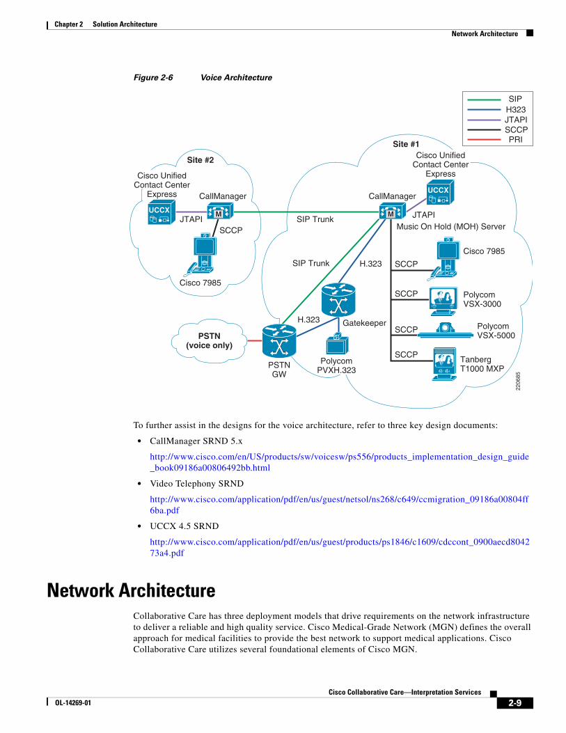
Figure 2-6 Voice Architecture
To further assist in the designs for the voice architecture, refer to three key design documents:
• CallManager SRND 5.x
http://www.cisco.com/en/US/products/sw/voicesw/ps556/products_implementation_design_guide_book09186a00806492bb.html
• Video Telephony SRND
http://www.cisco.com/application/pdf/en/us/guest/netsol/ns268/c649/ccmigration_09186a00804ff6ba.pdf
• UCCX 4.5 SRND
http://www.cisco.com/application/pdf/en/us/guest/products/ps1846/c1609/cdccont_0900aecd804273a4.pdf
Network ArchitectureCollaborative Care has three deployment models that drive requirements on the network infrastructure to deliver a reliable and high quality service. Cisco Medical-Grade Network (MGN) defines the overall approach for medical facilities to provide the best network to support medical applications. Cisco Collaborative Care utilizes several foundational elements of Cisco MGN.
SIPH323JTAPISCCPPRI
PSTN(voice only)
Site #1
Site #2
CallManager CallManager
Cisco 7985
SCCPSIP Trunk
SIP Trunk
H.323
H.323
Gatekeeper
SCCP
Cisco 7985
TanbergT1000 MXP
Polycom VSX-3000
Polycom VSX-5000
Music On Hold (MOH) Server
SCCP
SCCP
SCCPPSTNGW
JTAPI JTAPI
2206
85
UCCX
UCCX M M
Cisco UnifiedContact Center
Express
Cisco UnifiedContact Center
Express
PolycomPVXH.323
2-9Cisco Collaborative Care—Interpretation Services
OL-14269-01

Chapter 2 Solution ArchitectureNetwork Architecture
To begin addressing the network architecture, we must identify the locations of the clinician, patient, and interpretation agent. The locations drive several elements of the architecture:
• Network readiness to support the traffic models of Collaborative Care
• Distributed or centralized call control for Cisco Unified CallManager and Cisco Unified Contact Center Express
• Places in the network that need to perform a site evaluation which may include the branch or campus designs
• The number of sites for a single hospital domain that need coverage drives the selection of the site-to-site connections
• If different hospital affiliations or a language interpretation provider need to interconnect their networks to link patients and translators, then a business-to-business IP connection needs to be selected.
Figure 2-7 Network Locations
The network locations figure shows a superset of the locations that need to be assessed for readiness to deliver voice and video traffic. To perform a thorough analysis refer to the following design documents:
• Branch Office Solution Reference Network Design Guide
http://www.cisco.com/application/pdf/en/us/guest/netsol/ns656/c649/cdccont_0900aecd80488134.pdf
• Campus Solution Reference Network Design Guide
http://www.cisco.com/application/pdf/en/us/guest/netsol/ns656/c649/cdccont_0900aecd804ab67d.pdf
Pt to Pt Lease Line(IPSEC VPN)
ServiceProviderMPLS VPN
Service
Private WAN(full mesh)
MAN/WAN
LTSP Branch orMain Campus
Hospital AMain Campus
Hospital BCampus Hospital B (Clinic)
Branch #2
Hospital B (Clinic)Branch #nHospital B (Clinic)
Branch #1
2206
86
2-10Cisco Collaborative Care—Interpretation Services
OL-14269-01

Chapter 2 Solution ArchitectureNetwork Architecture
• MAN/WAN Selection Guide
http://www.cisco.com/application/pdf/en/us/guest/netsol/ns656/c649/cdccont_0900aecd80488134.pdf
• Enterprise QoS Design Guide
http://www.cisco.com/application/pdf/en/us/guest/netsol/ns432/c649/ccmigration_09186a008049b062.pdf
Foundational technologies apply to each network location. An overall design approach that considers all the traffic models results in the best network design. Specific to Collaborative Care, Chapter 4, “Designing the Solution” provides more details on design aspects. Key factors that affect Collaborative Care traffic include:
• QoS
End-to-end design to handle traffic between a single site and multiple sites for the traffic types in Collaborative Care. The traffic types are:
– Call signalling traffic
– RTP video traffic
– RTP voice traffic
Proper management of these traffic classes impacts the overall experience for the interpretation experience.
• High Availability (HA)
An overall approach to network infrastructure availability ensures calls can be made at all times. The traffic types used for this service require IP connectivity. Therefore any failover to PSTN traffic does not allow the video features of Collaborative Care to be preserved. For site-to-site connectivity, ensure that multiple paths are available and each site is dual-home to the service provider. For campus and branch office, refer to the SRNDs for detailed HA designs.
• Security
– Adopting the Cisco Self Defending Network approach provides a holistic method to addressing network security. As you drill down on the specific areas of Collaborative Care there are two important architecture considerations to ensure traffic flows are maintained.
– Infrastructure security—These include best practices for campus, branch, and MAN/WAN security designs
– Application security—These include securing the H.323 and SIP signalling and script security
– Call Management security—This includes platform hardening for call control components
– Endpoint security—The phones should be authenticated and other best practices to load CSA on PC platforms that run softphone applications.
• Capacity Design
Each site evaluates traffic considerations to ensure the onsite and site-to-site capacities are factored. For Collaborative Care video, and to a smaller extent voice, traffic feeds into the overall capacity designs. The architecture should handle the peak call rates expected from each site to ensure bandwidth is provided. If bandwidth is a concern, then the system should use CallManager limits to restrict the calls to a limited peak to ensure bandwidth is not over-consumed. If bandwidth is over-consumed and proper QoS models have not been applied, the video and voice traffic experience clipping and packet loss.
2-11Cisco Collaborative Care—Interpretation Services
OL-14269-01

Chapter 2 Solution ArchitectureNetwork Architecture
Network ServicesThere are a number of network services that better facilitate the deployment of Cisco Collaborative Care services. These include, but are not limited to DNS, QoS, NAT/PAT, DHCP, HSRP, and PoE. While some of these services are optional, scalability and usability are greatly enhanced if these services are available.
• Dynamic Name Service (DNS)—Provides a translation mechanism from host name to IP address and is frequently available on most if not all current IP networks. The use of DNS becomes critical with some telephone endpoints to provide XML-based services, such as the IP Phone Agent (IPPA). Without properly functional DNS services available to the Cisco 7985, the use of the IPPA XML application is not possible.
• Quality of Service (QoS)—Available in most Cisco switches and routers. By enabling QoS services, the network can determine the level of service required for each packet traversing the device. When an endpoint registers to CallManager, it is directed to use a set of QoS markings (called Differentiated Services Code Point or DSCP). These markings are assigned to call control protocol packets as well as voice and video traffic. The network then uses these markings (if configured and enabled) to provide a higher level of service during times of congestion. This assures that the quality of the call is maintained during times of high network utilization.
• Network Address Translation and Port Address Translation (NAT/PAT)—Two separate techniques used to provide seamless integration between networks who use either private RFC-1918 IP address space or overlapping address space. NAT provides a 1:1 mapping between internal hosts and a pool of external facing IP addresses. PAT provides an oversubscription of internal hosts to a single external facing IP address. To distinguish traffic being received externally as belonging to a single host on the inside, PAT uses unique TCP port mapping to assure that each outgoing TCP flow is assigned a unique port address. Hence the name Port Address Translation. Cisco Collaborative Care has been tested with both NAT and PAT using SIP trunks between call managers.
• Dynamic Host Configuration Protocol (DHCP)—Used to dynamically assign an IP address to hosts. In addition to the IP address, other optional information can and is supplied to the requesting host. Some examples of these DHCP options include but are not limited to default gateway, domain name, NTP time servers, and DNS Servers. Cisco-based IP telephony endpoints use DHCP option 150 to locate the IP address of the server running the TFTP (Trivial File Transfer Protocol), which in most cases is the CallManager server. The availability of DHCP is therefore critical for the successful registration of a VoIP endpoint to the CallManager cluster.
• Hot Standby Routing Protocol (HSRP)—The HSRP protocol can be used to provide edge level redundancy. HSRP allows one router to automatically assume the function of the second edge router if the second router fails. HSRP is particularly useful when the users on one subnet require continuous access to resources in the network and provides a level of redundancy in the event of an edge router failure.
• Power over Ethernet (PoE)—A network service that provides power to endpoints when connected to a device that is PoE enabled. This is a hardware requirement of the Ethernet switch and comes in two flavors in Cisco switches. This is a Cisco pre-standard form of the later ratified 802.11af standard. External AC adapters are available for each Cisco IP telephone, and may supplement areas where PoE is not currently available. Use caution when designing a voice-enabled network where external AC adapters are being used to power phones; in such cases an Interruptible Power Supply should be deployed. It is recommended that each PoE-enabled switch be connected to an interruptible power source to provide voice services during power outages.
2-12Cisco Collaborative Care—Interpretation Services
OL-14269-01

Chapter 2 Solution ArchitectureUnified Contact Center Express (UCCX) Architecture
Unified Contact Center Express (UCCX) Architecture
ArchitectureThe Unified Contact Center Express server contains all of the main components that were capable of being separated in earlier releases of Unified Contact Center Express. These components include the CRS Engine, Database Server, and Recording and Monitoring components.
Because Unified Contact Center Express 4.5 is designed to work with CallManager 5.0 and 5.1, it no longer has accessibility to the LDAP service found in earlier releases of CallManager. For this reason, all configuration settings are stored locally on the Unified Contact Center Express server in a series of XML files.
Scripts and applications are now stored in the CRS Database and are located on the Unified Contact Center Express server. The CRS database uses Microsoft SQL Server (SQL2K) which is installed as part of the Unified Contact Center Express installation process.
Unified Contact Center Express uses an API called AXL (AVVID XML Layer) to communicate with CallManager. As such, CallManager must have the AXL services installed and active.
An overview of the Cisco Unified Contact Center Express architecture is shown in Figure 2-8.
Table 2-1 Power over Ethernet
Catalyst 6500
Catalyst 4500
Catalyst 3750
Catalyst 3560
Catalyst 3550
Cisco Ethernet Switch Module
IEEE 802.af Yes Yes Yes Yes No No
Cisco pre-standard PoE Yes Yes Yes Yes Yes Yes
2-13Cisco Collaborative Care—Interpretation Services
OL-14269-01

Chapter 2 Solution ArchitectureUnified Contact Center Express (UCCX) Architecture
Figure 2-8 UCCX Architecture
UCCX provides the key component to support the business logic for the service. CallManager relies on the logic in UCCX to find a translator with the right skill set. If the agent cannot be found, then UCCX handles the queuing of the calls until an agent is available. The distributed management splits the management for the agent. The call control utilizes SCCP to control the phone. CAD is also used to allow the agent to set states for UCCX to determine availability of the agent when they are not connected on a call. For example, an agent may be processing information from their previous call. While the call is not connected in CallManager, the agent may not want to receive calls until they have completed the transactions. CAD allows the agent to communicate these states to UCCX.
The UCCX server contains all of the main components that were capable of being separated in earlier releases of UCCX. These components include the CRS Engine, Database Server, and Recording and Monitoring components.
UCCX Express Components • IVR scripts—This function of UCCX allows the customer to customize the logic of the contact
center to meet the needs of the hospital or LIS. This environment is a programmable script environment. In the script, the user can be directed through the search logic to find the interpretation agent with the proper skillset to handle the consultation. These search factors may include language type, hearing impaired, and gender, among other attributes.
CTI ControlRTP H.264 Video and G722 Autio Streams
HistoricalDatabase
Language Interpretation Agent
Cisco Agent Desktop (CAD)
Cisco 7985
2207
80
M
Clinician
Cisco 7985
UCCX
UCC Express 4.5.2
Agent-JTAPI
CTI-JTAPI
IP IVR
IP Queue Manager
SCRIPTS
MOHXFER
CallManager 5.x
CTI Manager
Call Control
CTI PortCTI Port
CTI Port
CTIRoute Point
Media ControlSIPSCCP
V
2-14Cisco Collaborative Care—Interpretation Services
OL-14269-01

Chapter 2 Solution ArchitectureSystem Call Flow
• CTI-JTAPI—These ports acts as a link or portal from the CTI Route Point (Pilot Number) to the applications (IVR Scripts). The CTI interface, in addition, helps deliver content (database lookups, web site applications, etc.) to the agent’s desktop.
• Agent-JTAPI—This port allows the agent to communicate with UCCX via the CAD or IPPA JTAPI interface. This interface allows the agent to indicated to UCCX the unique states into which a specific agent may be placed.
• IP Queue Manager—This function in UCCX acts as a queuing location for calls when no agents are available for that particular skillset queue. Music on hold and transfer of calls out of queue are among some of the functions leveraged by the IP Queue Manager.
CallManager 5.x Components • CTI Manager—The CTI manager is the function to handle calls routed to a particular destination
number that maps to an UCCX queue. This CTI Manager handles the communication with UCCX to dually provide the call logic to handle the processing of the call made to find an interpretation agent.
• Call Control—This function handles the call routing logic for calls and call states.
• Media Control—This function is critical to negotiate the voice, video, and DTMF capabilities for the call.
System Call FlowThe system call flow for Collaborative Care is outlined in this section. The call flow is factored mainly for the Unified Communication components. The calls made in this solution always originate from the clinician and/or patient trying to find a translator by dialing into a main number at a Contact Center that hosts interpretation agents. As the clinician and patient dial into the contact center IVR system, the UCCX scripts activate and walks the caller through a skill set selection algorithm. This algorithm is customized to fit the individual needs for the business, but a sample algorithm is used in this design guide to provide guidance. As the skill set selection process is completed, the call is then routed to an agent if agents are available, to a calling queue to wait for the next available agent, or the call may be transferred to another supporting site that may have more skills to meet the skill set requested. The UCCX environment is designed to be highly customizable to build logical algorithms to support the business needs. Other options are provided in Chapter 4, “Designing the Solution” for methods to simplify the process of matching the clinician and patient with the right skill set of the agent.
Variations for these calls model may exist, however, these calls are primarily derived from point-to-point calls. These point-to-point calls are managed and handled solely by the Cisco CallManager. Standard bearer negotiations for point-to-point calls are handled by the Cisco CallManager and not considered in this design guide.
The system call flow has implications for the network infrastructure including QoS, security, and several other factors. These network implications are further outlined in Chapter 4, “Designing the Solution.”
2-15Cisco Collaborative Care—Interpretation Services
OL-14269-01

Chapter 2 Solution ArchitectureSystem Call Flow
Figure 2-9 Finding an Interpretation Agent System Call Flow
1. Clinician dials a pilot phone number for translation services.
2. CallManager informs UCCX that inbound call has arrived.
3. Call flow:
a. If UCCX has available resources, UCCX informs CallManager of the CTI port to which the call should be directed. UCCX accepts call and starts the Application Script associated with the Pilot Number dialed. UCCX provides audio port to CallManager to communicate it to the endpoint.
b. CallManager communicates the RTP audio port obtained from UCCX for IVR prompts to be played to the endpoint. Endpoint establishes the RTP stream to UCCX.
c. UCCX interacts with user playing prompts as user interacts with IVR menu.
4. Call flow:
a. Clinician interacts with IVR menu driven by IVR Script. Keystrokes between endpoint and CallManager are Out-of-Band DTMF.
b. CallManager passes user keystroke inputs to UCCX using JTAPI protocol.
5. Call flow:
a. UCCX Script instructs CallManager to put call on interruptible hold until agent is available.
b. CallManager plays MOH to caller awaiting keystroke inputs in the event that the caller wants to escalate the call.
5b
5c
CallManager
2206
88Clinician and Patient
CAD orIPPA
LogicalUCCX Queue
6a
8 3c4a 1
6b3a 5a2
3b
5b
7b
7c
7a
4bUCCX
M
M
M M
M
2-16Cisco Collaborative Care—Interpretation Services
OL-14269-01

Chapter 2 Solution ArchitecturePartner Considerations
c. Clinician waits in logical hold queue.
6. Call flow:
a. Agent becomes available.
b. UCCX informs CallManager that a particular agent is available for the next available call in the logical hold queue.
7. Call flow:
a. Clinician endpoint is told which agent to direct RTP streams to for call completion.
b. Agent receives a “screen pop” as to the incoming call via either Cisco Agent Desktop (CAD) or the XML-based IP Phone Agent (IPPA).
c. Agent and Clinician are connected and establish RTP audio and video streams.
8. Translation Agent transitions to “Not Ready” state while call is in session.
Partner ConsiderationsFor Collaborative Care there different categories of partners that should be considered:
• Video IP endpoint partners—This type of partner provides the IP-enabled video endpoints that fit the specification defined for Collaborative Care. These endpoints are further described in Chapter 3, “Solution Features and Components.” Polycom and Tandberg are the two equipment providers that Cisco has partnered with for video IP endpoints.
• System integration partner—This type of partner assists the hospital or LIS in designing and implementing Collaborative Care based on this design guide. The skillset required from this partner varies from Unified Communications, network readiness assessment and design, and also UCCX scripting expertise to build a script that matches the business requirements.
• Language interpretation provider partner—This partner is a key enabler to find a broad range of interpretation language skillsets or sign language skillsets.
2-17Cisco Collaborative Care—Interpretation Services
OL-14269-01

Chapter 2 Solution ArchitecturePartner Considerations
2-18Cisco Collaborative Care—Interpretation Services
OL-14269-01

OL-14269-01
C H A P T E R3
Solution Features and ComponentsSolution Features List • Voice or Voice + Video call options
• SIF (352x288 resolution) video calls with H.264 high video compression
• Bettern than PSTN voice quality with G.722 wideband codec
• Variety of clinician endpoints (PC-based or hard endpoint) with built in video display, camera, voice, and echo cancellation capabilities
• Fast routing to interpretation agent or queue
• Priority queuing and call escalation
• Call routing based on skill attributes to appropriate queues based on IVR
• Calls in queues are provided with a status of wait time and option for emergency service escalation
• Calls in queues have music on hold
• Customizable IVR scripts to meet business requirements
• Multiple deployment models to meet business needs
• Solution is multi-lingual and supports Sign Language
• Scales up to 50 queues and 300 concurrent sessions
• Interpretation agents can be associated to multiple skill groups
• Secured with firewall with dynamic pinhole for voice and video ports
• NAT and PAT support
Solution ComponentsThe solution components required for Collaborative Care span across several key technologies. These technologies used in combination address the requirements to enable interpretation services:
• Call control—The components used here help manage the endpoints used by the clinician and patient to make calls into the contact center to find an interpretation agent. Call control also is required to manage the endpoints used by the agents that serve as translators. The key highlights for the call control components include dial plan management, resource management of the voice and video calls, call routing to the appropriate locations for the calls based on various deployment model designs, and site to site interconnectivity.
3-1Cisco Collaborative Care—Interpretation Services

Chapter 3 Solution Features and ComponentsCall Control Components
• Contact center—These components help specifically manage the logic for the selection of skill attributes to find the proper interpretation agent. In addition, the availability of interpretations agents to service the call or the need to place calls in queues are managed by the contact center components. The scripting environment offered by the contact center addresses the variety of business models to join clinician/patients with the proper skill set of an agent.
• Endpoints—There are a range of endpoints that can be used for the clinician and patient that best meet the needs of the hospital or clinical environment. This endpoint functionality is critical to providing the video and voice quality to offer the best experience for the patient going through a translated consultation with their clinician.
• Infrastructure and security components—These elements consist of the routing, switching, and security components required to deliver the networking characteristics to deliver voice and video from clinician/patient to the interpretation agent. Key locations of the network include branch office, campus, and site-to-site WAN designs to meeting network service level goals.
Call Control ComponentsCisco Unified CallManager 5.1 is an enterprise IP telephony call processing solution that manages the endpoints and intelligently routes calls between the clinician making the call to the contact center system and then ultimately to the interpretation agent. The critical features utilized from CallManager include:
1. SCCP call control for endpoint negotiation of video codec capabilities for H.264 video and G.722 voice
2. SIP-T call control for CallManager to CallManager negotiation of video codec capabilities for H.264 video and G.722 voice
3. Support for Polycom partner endpoints
4. Integration with Contact Center for call selections through IVR scripts
5. Protocol translations between H.323 endpoints, SCCP endpoints, and SIP Trunks
The Cisco IOS H.323 Gatekeeper is a feature set supported in Cisco IOS platforms that enables H.323 management for H.323 endpoints used in this solution. Voice and video H.323-enabled endpoints are registered to Cisco H.323 Gatekeepers. User authentication, call authorization, and admission control for calls from and to H.323 endpoints are handled by the gatekeeper. In addition, address resolution and translation between E.164 address and IP address are also configured and controlled by the gatekeeper.
Table 3-1 Call Control Solution Components with Supported Software Release
Component Functional Description HW/SW Releases
Cisco Unified Call Manager Call Control and resource management for voice and video enabled endpoints
CallManager 5.1(1b)
Cisco IOS H.323 Gatekeeper
H.323 management for all H.323 enabled endpoints and registration of CallManager
Cisco IOS 12.4(11)T
3-2Cisco Collaborative Care—Interpretation Services
OL-14269-01

Chapter 3 Solution Features and ComponentsContact Center Components
Contact Center ComponentsThe Cisco Unified Contact Center Express (UCCX) offers an easy-to-deploy, easy-to-use contact center that provides sophisticated customer interaction management for up to 300 agents. The flexibility offered through Unified Contact Center Express can handle the complexity of skill set match between the clinician/patient with the interpretation agent. The interactive voice response (IVR) offers a voice menu system to accurately select the proper skill set required for the translator based on factors such as language, American Sign Language (ASL), and other patient preferences. This contact-center-in-a-box bundles all the functionality and the flexibility to allow hospitals to rapidly deploy an interpretation call center in house. At the same time it is powerful enough to offer the language interpretation provider the functionality to service multiple hospitals that may be grouped through a consortium.
Unique to the premium edition of the Unified Contact Center Express required for Collaborative care includes the functionality provided in the Advanced ACD features:
• Agent Skill and Competency-Based Routing—Agents can be configured with multiple skills (up to 50), each with a different competency level (up to 10). UCCX uses a concept called Contact Service Queues (CSQs). CSQs group similar customers together. CSQs can be configured as requiring multiple skills (up to 50), each with a different minimum skill competency level (up to 10). CSQs can also be defined with one of the following agent selection rules:
– Longest available, most handled contacts, or shortest average handle time
– Most skilled, most skilled by weight, or most skilled by order
– Least skilled, least skilled by weight, or least skilled by order
Agents are only associated with a CSQ if their skills and competencies exceed the minimum requirements of a CSQ. An UCCX routing script uses the select resource step to choose a resource (agent). In the select resource step, a CSQ is specified. The UCCX select resource step chooses an available agent from those associated with a CSQ by using the agent selection rule configured for that CSQ.
• Dynamic Reskilling—Changes to CSQ skills and competencies and agent skills and competencies are applied immediately.
• Prioritized Queuing—Customer contacts can be prioritized (up to 10 levels) based upon call or customer data and calls may be moved within or among queues under workflow control using priority information.
• Agent Routing—UCCX routing applications can select a specific agent if that agent is in a ready state.
3-3Cisco Collaborative Care—Interpretation Services
OL-14269-01

Chapter 3 Solution Features and ComponentsContact Center Components
Figure 3-1 Cisco Agent Desktop Interface
The Cisco Agent Desktop is a powerful Windows-based customer contact application that allows the interpretation agent to control the various states that an agent may be placed in. The simplest activity is to allow efficient login/logout functions for the interpretation agent. When the agent is logged in, the translator can place themselves in a variety of ACD states including ready, not-ready, and wrap-up to inform the contact center application of their availability to handle calls from the clinician.
For a complete compatibility matrix for Contact Center, see:
http://www.cisco.com/application/pdf/en/us/guest/products/ps1846/c1683/ccmigration_09186a008077cb33.pdf
Table 3-2 Contact Center Solution Components with Supported Software Release
Component Functional Description HW/SW Releases
Cisco Unified Contact Center Express—Premium
Contact Center management for the Interpretation Service
Release 4.5(2)
Windows 2000; 2000 4.2 SR8 (operating system)
Cisco Agent Desktop (CAD) Agent Desktop is a Windows-based customer contact application that provides the interpretation agent to manage the business process
Built into Cisco Unified Contact Center
6.2(1) (Premium Version) Build 6.2.0.19
3-4Cisco Collaborative Care—Interpretation Services
OL-14269-01

Chapter 3 Solution Features and ComponentsEndpoint Component
Endpoint ComponentEndpoints are IP-enabled devices that are used by the clinician and patient to make voice or voice and video combined calls into the contact center. The IP enabled endpoints are also used by the interpretation agent to receive calls that come into the contact center. While these endpoints may be used for other purposes, for the collaborative care solution this scenario is the primary use case.
The IP endpoints are categorized into three types:
• Cisco IP phone endpoints-Cisco IP endpoints that only function as voice
• Cisco IP video endpoint
• Partner IP video endpoints
Key capabilities required from the IP enabled endpoints are described in Table 3-3.
Table 3-3 IP Endpoint Capabilities
Functionality Description
Voice Format The process of taking samples of the voice packet and encoding them into voice packets that can then be delivered over an IP network. There are many types of voice encoding schemes. The primary voice codec used for this solution is G.722 which samples voice at 7kHz.
Speakerphone Ability for the endpoint to have handsfree functionality which is mandatory for the clinician and patient.
Integrated Microphone and Echo Cancellation
The microphone captures the voice, where some microphones have directional capabilities to capture voice better from certain positions. Echo cancellation helps eliminate feedback to hear your own voice played back.
Video Format The process of taking samples of the video stream from the camera and encoding them into packets that can be delivered over an IP network. There are several encoding schemes. The format used for this solution is MPEG4 Part 10.
Video Resolution This term describes the fixed-pixel-array that is displayed on the video screen. The number is provided as A x B. A is equal to the physical number of columns and B is equal to the physical number of rows of pixels. Used for this solution is SIF (352x288).
Built-in Video Camera In the IP endpoints that are video enabled, the majority of the devices have built-in IP video cameras that will capture the images of the clinician/patient or the interpretation agent.
Pan, Tilt, Zoom (PTZ) Panning refers to the horizontal movement or rotation of a video camera or the scanning of a subject horizontally on video.
Tilting refers to the vertical movement or rotation of a video camera
Zooming is a mechanical method of the lens to vary its focal length to capture the image which allows for a closer or farther view of the image being captured.
Picture in picture (PIP) This feature enables the viewer to see a secondary image on the same display screen that shows the image of themselves overlaid on the image of the destination party.
3-5Cisco Collaborative Care—Interpretation Services
OL-14269-01

Chapter 3 Solution Features and ComponentsEndpoint Component
Each endpoint is classified for usage in the tables below. All the IP endpoint types can be used for the clinician and patient side. However for the IP endpoints to function as an interpretation agent endpoint, the phone requires integration with CAD. Only the Cisco IP endpoints are currently integrated with CAD.
Cisco EndpointsCisco offers a variety of IP endpoints that are voice enabled. Cisco also offers an integrated IP video endpoint in the Cisco 7985. Each of these endpoints are based on using SCCP to control the phones from Call Manager. If video is not required, Cisco offers a range of IP voice endpoints, only some of which are listed in Table 3-4. To ensure qualification for an interpretation agent phone, check that the Cisco IP phone is compatible with CAD.
Video Screen Display Many of the IP endpoints include a built-in LCD display. The endpoints being considered vary in size from 8.4" LCD to 17" LCD. The display resolution varies, however the video stream is still delivered at 352x288 resolution.
Frame Rate The frame rate is captured in frames per second. This term is used for the measurement of the quickness a video endpoint produces unique consecutive images. The minimum fps desired is 25fps.
Call Signalling Protocol
This term refers to the call control protocol used between the call control components and the IP endpoints used in the solution. This protocol controls the call states, bearer channel negotiations, digit collection, and other factors that relate to the call. There are three protocols used in this solution including H.323, SIP, and SCCP.
DTMF Method This terms defines the method by which an IP endpoint transmits Dual-tone multi-frequency (DTMF) between itself and the destination device. For IVR prompts to the contact center, DTMF is required to be sent via out-of-band (OOB) methods; that is, the tones are not imbedded into the voice stream, but sent through the call signalling path. Each call control protocol has a method for OOB DTMF.
Additional Ethernet Port
This capability allows a PC to be attached to the phone since some office locations are only wired for a single Ethernet port. This allows the PC to connect to the IP phone then into the wall jack.
CAD Integration This functionality is required for the interpretation agent to interact with the Contact Center. For this to work, the phone must be integrated with CAD.
Table 3-3 IP Endpoint Capabilities
Functionality Description
3-6Cisco Collaborative Care—Interpretation Services
OL-14269-01

Chapter 3 Solution Features and ComponentsEndpoint Component
Figure 3-2 Cisco 7985 IP Video Phone
Cisco Unified IP Phone 7985G has all the components to enable a video call-camera, LCD screen, speaker, keypad, and a handset-incorporated into one easy-to-use unit.
Note Go to CCO to download 4.1.3.0, which is not currently part of the start device pack. The image can be found on the CCO download page. http://www.cisco.com/cgi-bin/tablebuild.pl/ip-7900ser
Polycom Video EndpointsPolycom is a key Cisco partner that offers a range of IP video endpoints that may be used in the Collaborative Care solution. Depending on the functions listed in Table 3-8 and Table 3-9, choose your endpoint accordingly. Polycom offers three different forms of endpoints:
• A software application, Polycom PVX, that runs on Microsoft Windows. This endpoint is ideal for hospitals that make use of PCs in the patient rooms. A good option is to utilize Tablet PCs for greater portability. This software application works in conjunction with your PC and USB camera to provide
Table 3-4 Cisco Endpoints with Supported Software Release
Component Functional Description HW/SW Releases Usage
Cisco 7985 Cisco IP video-enabled endpoint
Standard device pack—cmterm_7985.4-1-3-0
Clinician/patient phone
Interpretation agent phone
Cisco 7971 Cisco IP voice endpoint
Standard device pack—SCCP70.8-2-1S Clinician/patient phone
Interpretation agent phone
Cisco 7961 Cisco IP voice endpoint
Standard device pack—SCCP41.8-2-1S Clinician/patient phone
Interpretation agent phone
Cisco 7941 Cisco IP voice endpoint
Standard device pack—SCCP41.8-2-1S Clinician/patient phone
Interpretation agent phone
3-7Cisco Collaborative Care—Interpretation Services
OL-14269-01

Chapter 3 Solution Features and ComponentsEndpoint Component
the high-quality video and audio experience. The PC requires the addition of a USB camera which may also integrate a built-in microphone with echo cancellation. If not, then an additional device is required for microphone and echo cancellation capabilities. For Collaborative Care, the PVX uses H.323 to register to a Cisco H.323 Gatekeeper and communicates with CallManager via H.323.
Figure 3-3 Polycom PVX Product
For specific details on the Polycom PVX, check the Polycom website at:
http://www.polycom.com/products_services/1,,pw-35-4367-7953,FF.html
Figure 3-4 Polycom Computer Calling Kit Product
For a USB microphone, consider the Polycom Computer Calling Kit at their website:
http://www.polycom.com/products_services/1,,pw-12094,FF.html
• For a large LCD screen acting as an integrated IP video endpoint, consider the VSX-3000. The Polycom VSX-3000 delivers an integrated, high-quality video conference solution. As a fully integrated video conferencing system, the Polycom VSX-3000 offers a solution in a shared environment, delivering ease of use with powerful video and audio performance. The Polycom VSX-3000 also can double as a PC display when not on a video call, saving valuable desk space. For Collaborative Care, the VSX-3000 uses the SCCP protocol for communication with Call Manager.
3-8Cisco Collaborative Care—Interpretation Services
OL-14269-01

Chapter 3 Solution Features and ComponentsEndpoint Component
Figure 3-5 Polycom VSX-3000 Product
For specific details on the Polycom VSX-3000, check the Polycom web site at:
http://www.polycom.com/products_services/0,,pw-4367-6197,00.html
• For a IP video endpoint that integrates with any TV or XGA external display, consider the VSX-5000. The VSX-5000 enables video conferencing for small meeting spaces that would be ideal for larger rooms in a clinician and patient consultation. For Collaborative Care, the VSX-5000 uses the SCCP protocol for communication with Call Manager.
Figure 3-6 Polycom VSX-5000 Product
For specific details on the Polycom VSX-5000, check the Polycom web site at:
http://www.polycom.com/products_services/1,1443,pw-185-11034,00.html
3-9Cisco Collaborative Care—Interpretation Services
OL-14269-01

Chapter 3 Solution Features and ComponentsTandberg Video Endpoints
Tandberg Video EndpointsTandberg is a key Cisco partner that offers an IP video endpoints that may be used in the Collaborative Care solution. Depending on the functions listed in Table 3-7 and Table 3-8, choose your endpoint accordingly. Tandberg offers a T1000 MXP IP Video Phone that offers the following capabilities:
• Completely integrated system including camera, 12.1” LCD screen, speakers, cables, and microphone
• True business-quality video
• XGA LCD Screen
• SCCP, SIP, H.323 and H.320 support
• Ultra-thin portable frame
• Optional wall-mount bracket
Table 3-5 Polycom Video Endpoints with Supported Software Release
Component Functional DescriptionHW/SW Releases Usage
Polycom PVX H.323 software application that delivers premium quality audio, video, and content from your PC and USB camera
8.0.2.0235 Clinician/patient phone
Polycom VSX-3000
SCCP endpoint that delivers an integrated, high-quality video conference with a built-in monitor
8.6 (beta) Clinician/patient phone
Polycom VSX-5000
Compact video conferencing with premium video and audio performance that connects to TV or XGA display.
8.6 (beta) Clinician/patient phone
3-10Cisco Collaborative Care—Interpretation Services
OL-14269-01

Chapter 3 Solution Features and ComponentsInfrastructure and Security Component
Figure 3-7 Tandberg T1000 MXP
For specific detail on the Tandberg T1000 MXP, check the Tandberg web site at:
http://www.tandberg.com/products/video_systems/tandberg_1000_mxp_cisco.jsp
Infrastructure and Security ComponentAs part of the Collaborative Care solution, the network infrastructure requires a level of capabilities to ensure that the real-time data for voice and video are delivered to the design goals described in Chapter 4, “Designing the Solution.” This foundation is part of Cisco Medical-Grade Network for Hospitals to lay the foundations for Collaborative Care traffic as well as all other traffic types traversing through the Hospital network.
As part of the Cisco Medical-Grade Network, there are three specific network locations that use Cisco SRND designs to ensure the highest quality of design and implementation. These include the branch office, the campus network, and the MAN/WAN designs for site-to-site connectivity.
The validated solution for Collaborative Care was built on the components and software releases listed in Table 3-7.
Note Cisco's Solution Reference Network Design guides are available at http://www.cisco.com/go/srnd.
Table 3-6 Tandberg T1000 MXP
Component Functional Description HW/SW Releases Usage
Tandberg T1000 MXP SCCP endpoint that delivers an integrated, high-quality video conference with a built-in monitor
M2.2beta Clinician/patient phone
3-11Cisco Collaborative Care—Interpretation Services
OL-14269-01

Chapter 3 Solution Features and ComponentsFunctionality Map for IP Endpoints
Functionality Map for IP EndpointsSeveral key functions for the IP endpoints have been outlined. Table 3-8 and Table 3-9 provide a mapping of functionality against the individual endpoints. For more information specific to each endpoint, refer to the respective data sheets.
Table 3-7 Infrastructure and Security Solution Components with Supported Software Release
Component Functional Description HW/SW Releases
Cisco ASA Provides the firewall ACL functionality to block unwanted traffic.
Also provides the NAT/PAT functionality.
SIP inspect aware for voice and video traffic types supported by Collaborative Care.
7.2.2 (10)
Cisco Edge Router (ISR) The edge router that resides on the internet edge or on the MAN/WAN edge for site-to-site connectivity
12.4(11)T
Campus/Branch Switch The Layer 2/Layer 3 access switch for a campus or branch office design
12.2(25)SEC2
Cisco MAN/WAN/MPLS VPN
Provides site-to-site for hospitals to connect among themselves.
Also provides site-to-site connectivity for inter-hospital connections or to the LIS. Critical for business-to-business (B2B) connections.
Based on recommendations from Layer 3 MPLS VPN Enterprise Consumer Guide Version 2
Table 3-8 Functionality Map for IP Endpoints
Endpoint Video format Speakerphone
Integrated Microphone and Echo Cancellation Voice Format
Video Resolution
Built-in Video Camera PTZ
Cisco 7985 H.264 MPEG4 Part 10
Yes Yes G.722 SIF (352x288) yes Tilt only
Cisco 7971 N/A Yes Yes G.722 N/A N/A N/A
Cisco 7961 N/A Yes Yes G.722 N/A N/A N/A
Cisco 7941 N/A Yes Yes G.722 N/A N/A N/A
Polycom PVX H.264 MPEG4 Part 10
Requires an add-on to PC
Requires an add-on to PC
G.722 SIF (352x288) No, USB camera
Based on USB camera
Tandberg T1000 MXP
H.264 MPEG4 Part 10
Yes Yes G.722 SIF (352x288) Yes Tilt only
3-12Cisco Collaborative Care—Interpretation Services
OL-14269-01

Chapter 3 Solution Features and ComponentsPolycom PVX Recommendations
Polycom PVX RecommendationsPolycom PVX requires a USB Camera to capture video from the PC application. There are minimum PC recommendations required to run the Polycom PVX. All information for Polycom PVX can be found on Polycom's website.
For camera recommendations, check:
http://www.polycom.com/common/pw_cmp_updateDocKeywords/0,1687,4556,00.pdf
Polycom recommends the following cameras:
• AVerMedia AVerTV GO 007 FM Plus PCI
• Creative WebCam Live! Motion
• Creative WebCam Live! Pro
Polycom VSX-3000
H.264 MPEG4 Part 10
Yes Yes G.722 SIF (352x288) yes Tilt only
Polycom VSX-5000
H.264 MPEG4 Part 10
Yes Yes G.722 SIF (352x288) yes Local Remote
Table 3-9 Functionality Map for IP Endpoints continued
Endpoint PIPVideo Screen Display
Frame Rate
Call Signalling Protocol DTMF
Power over Ethernet
Additional Ethernet Port
CAD Integration
Cisco 7985 Yes 8.4" LCD 30fps SCCP SCCP OOB 802.3af (class 3) Yes Yes
Cisco 7971 N/A N/A N/A SCCP SCCP OOB 802.3af (class 3) Yes Yes
Cisco 7961 N/A N/A N/A SCCP SCCP OOB 802.3af (class 3) Yes Yes
Cisco 7941 N/A N/A N/A SCCP SCCP OOB 802.3af (class 3) Yes Yes
Tandberg T1000 MXP
Yes 12.1” LCD 30fps SCCP SCCP OOB A/C adaptor required
No No
Polycom PVX
Yes Based on PC Tablet used for application
30fps H.323 Inband (cannot access IVR)
A/C adaptor required
N/A, PC based No
Polycom VSX-3000
Yes 17 LCD 30fps SCCP Inband (cannot access IVR)
A/C adaptor required
No No
Polycom VSX-5000
Yes Depends on LCD monitor
30 fps SCCP Inband (cannot access IVR)
A/C adaptor required
No No
Table 3-8 Functionality Map for IP Endpoints
Endpoint Video format Speakerphone
Integrated Microphone and Echo Cancellation Voice Format
Video Resolution
Built-in Video Camera PTZ
3-13Cisco Collaborative Care—Interpretation Services
OL-14269-01

Chapter 3 Solution Features and ComponentsPolycom PVX Recommendations
• GlobalMedia iREZ KD 1394
• GlobalMedia iREZ K2 USB 2.0
• Logitech QuickCam Pro 4000
• LogiTech QuickCam for Notebooks Pro
• Logitech QuickCam Pro 5000
• Logitech QuickCam Fusion
• Logitech QuickCam Orbit MP
• Veo Velocity Connect
• V-Stream TV2800 (V-Stream Xpert DVD Maker USB 2.0)
For the Collaborative Care solution, the following cameras were tested:
• GlobalMedia iREZ K2 USB 2.0
• LogiTech QuickCam for Notebooks Pro
• Logitech QuickCam Fusion
• LogiTech Ultra Fusion
In the design section, specific bandwidth measurements and perceived video quality are provided.
3-14Cisco Collaborative Care—Interpretation Services
OL-14269-01

OL-14269-01
C H A P T E R4
Designing the SolutionThis chapter contains information about interoperability, interconnection, capacity, bandwidth, interface requirements, connectivity, security, capacity, QoS, and scalability. However, the focus of this chapter is on providing design guidance in these areas that is specific to Collaborative Care. This chapter is not meant to be a design guide for high availability or other technologies.
Scalability and Capacity Planning
Network ScalabilityNetwork scalability can be broken down into two major disciplines, LAN and WAN connectivity. The following sections take a closer look at the issues pertaining to each.
LAN Scalability
All Unified Communications deployments assume that the Layer 2 network is composed of Ethernet switches and does not contain any shared non-switched, collision domain-based network infrastructure components. Furthermore, the Cisco Medical-Grade Network architecture recommends that best practices for Campus design be utilized in all deployments. This design describes the Local Area Network as being typically composed of three common layers, access, distribution, and core. Connectivity between each of these layers should be both redundant and have link speeds of 1Gbps or greater.
Figure 4-1 depicts one typical campus design deployment scenario.
4-1Cisco Collaborative Care—Interpretation Services

Chapter 4 Designing the SolutionScalability and Capacity Planning
Figure 4-1 Campus Design Deployment Scenario
Note For more information on Campus HA, see: http://www.cisco.com/application/pdf/en/us/guest/netsol/ns432/c649/cdccont_0900aecd801a8a2d.pdf.
PoE Scalability
One advantage of the hierarchal approach described above is that the design lends itself to quick expandability. The need for additional Power over Ethernet (PoE) ports may become necessary as additional Ethernet access is required in examination rooms that did not have Ethernet connectivity before the deployment of Cisco Collaborative Care—Language Interpreter Services.
An access layer capable of providing Quality of Service (QoS) is required to support the end-to-end service levels that are required for optimum delivery of voice and video services. To support high-quality and reliable voice and video, it is necessary to employ QoS services end-to-end in the network. If QoS mechanisms are not employed end-to-end, the usability of the solution comes into play, possibly resulting in poor acceptance of the solution by clinical staff. A more detailed discussion of QoS is contained in Quality of Service.
The PoE scalability requirements at the access layer can sometimes be overlooked. Proper planning, including but not limited to heat dissipation, uninterruptible power, and class of devices being connected to the access layer must be considered.
1327
01
WAN InternetData Center
High Speed Core
Distribution Block
4-2Cisco Collaborative Care—Interpretation Services
OL-14269-01

Chapter 4 Designing the SolutionScalability and Capacity Planning
Endpoints require different levels of power and by means of the 802.3af PoE specification can request a specific class of power delivery.
Some other examples of LAN scalability factors within the Access Layer to address bandwidth, security, and QoS are discussed in the next section. These techniques are not the entire scope of methods that should be considered, but offer some reasonable approaches.
EtherChannel
To increase the bandwidth delivered into the Access Layer (wiring closets), use an EtherChannel. Gigabit EtherChannel allows multiple Layer 2 links to be logically bonded together and appear as one interface with the aggregate bandwidth of the sum of the interfaces within the Gigabit EtherChannel
Table 4-1 Endpoint Power Levels
Class Usage Power Level Used in Power Budget Pool Maximum Power Levels
0 Default 15.4 Watts 0.44 - 12.95 Watts
1 Optional 4.0 Watts 0.44 - 3.84 Watts
2 Optional 7.0 Watts 3.84 - 6.49 Watts
3 Optional 15.4 Watts 6.49 - 12.95 Watts
4 Optional 15.4 Watts Reserved for Future Use
Table 4-2 Device Power Levels
Device802.3af Power Class
Cisco Pre-Standard PoE
Local Ethernet Port for PC Connectivity
AC Power Adapter Available
Audio Only Endpoints
Cisco Unified IP Phone 7941G Class 2 Yes Yes (10/100) Yes, Optional
Cisco Unified IP Phone 7961G Class 2 Yes Yes (10/100) Yes, Optional
Cisco Unified IP Phone 7970G Class 3 Yes1
1. Note that for full brightness, must use 802.3af Class 3, otherwise ½ brightness.
Yes (10/100) Yes, Optional
Cisco Unified IP Phone 7941G-GE Class 3 No Yes (10/100/1000) Yes, Optional
Cisco Unified IP Phone 7961G-GE Class 3 No Yes (10/100/1000) Yes, Optional
Cisco Unified IP Phone 7971G-GE Class 3 No Yes (10/100/1000) Yes, Optional
Video Enabled Endpoint
Cisco Unified IP Phone 7985G-GE Class 02
2. To achieve full brightness, external AC is required; otherwise LCDs have reduced brightness.
No Yes (10/100) Yes, Supplied
Polycom VSX-3000 N/A N/A No Yes, Supplied
Polycom VSX-5000 N/A N/A No Yes3
3. Supplied (video display separately purchased).
Tandberg T1000 MXP N/A N/A No Yes, Supplied
4-3Cisco Collaborative Care—Interpretation Services
OL-14269-01

Chapter 4 Designing the SolutionScalability and Capacity Planning
bundle. The ability to bond up to eight links provides a flexible mechanism to increase the aggregate bandwidth delivered to the access layer. The use of EtherChannel is not limited to Gigabit links and also includes FastEthernet and 10 Gig interface types.
Traffic passing through an EtherChannel bundle is load balanced across the individual links in the bundle. Depending on the switching hardware and software versions deployed, load balancing is typically dependant on the destination MAC address. Newer versions of IOS, Stackable Switches, and Supervisor modules have extended the load balancing algorithm such that Layer 3 forwarding decisions can be made at wire speed.
The recommendation is to use EtherChannel to augment bandwidth delivery to the access layer when link upgrades are not possible. It is also a good idea to properly understand the load balancing algorithms used by your network hardware. An excellent reference can be found in the document titled Understanding EtherChannel Load Balancing and Redundancy on Catalyst Switches which can be found on Cisco’s website at: http://www.cisco.com/en/US/tech/tk389/tk213/technologies_tech_note09186a0080094714.shtml
Figure 4-2 EtherChannel
802.1Q Trunking
802.1Q trunks allow a single uplink (which may be part of an EtherChannel bundle or not) to carry multiple Layer 2 VLANs. This technique is useful when it is desirable to assign various ports at the access layer to different VLANs. Each VLAN is then used to carry a particular type of traffic, such as voice, data, medical device, guest access, etc. This can be employed to separate at Layer 2 voice and video traffic associated with the Language Interpretation solution.
By using 802.1Q trunks in the access layer, the network administrator can isolate traffic and provide a means to more easily facilitate the delivery of a wide range of traffic types on a single converged access layer switch.
Figure 4-3 802.1Q Trunking
Bandwidth Management Techniques
The requirement for end-to-end QoS has been discussed earlier in this document and an in-depth analysis of the QoS requirements are discussed in Quality of Service. However, there are a number of other mechanism that should be considered for the control and elimination of traffic:
Catalyst 2950Catalyst 6500
EtherChannelFa4/2Fa4/3Fa4/4Fa4/5
Fa0/2Fa0/3Fa0/4Fa0/5 22
0786
Trunk
VLAN 1 and VLAN 2
VLAN 1
VLAN 2
VLAN 1
VLAN 2 SbSa 2207
87
4-4Cisco Collaborative Care—Interpretation Services
OL-14269-01

Chapter 4 Designing the SolutionScalability and Capacity Planning
• Protocol filtering provides the ability to filter un-necessary traffic that may be generated by misconfigured hosts. Such hosts may generate Appletalk, DECnet, or IPX traffic. Through the use of protocol filtering on Layer 3 access switches, this traffic can be prevented from consuming bandwidth on the uplinks to the distribution or core layer.
VLAN-based load balancing across multiple uplinks can increase the aggregated bandwidth in the event that EtherChannel technology has not been employed. This can provide greater uplink capacity from the access layer switches to the distribution layer. In the event that an access layer switch has two uplinks to the distribution or core, in most situations, by default one of these links is in a blocking state as determined by spanning-tree. The function of spanning-tree is to detect and eliminate Layer 2 loops in the network. To use these two links and effectively increase the bandwidth delivered to the access layer, change the spanning-tree port cost of the VLANs which make up the 802.1q trunk uplink. One typical approach is to direct all even-numbered VLANs on the first uplink from the switch fabric and all odd-numbered VLANs on the second uplink. Any technique used that results in more fully utilizing the uplink capacity delivered to the access layer is better then having only 50% of the available bandwidth in use at any one time.
To effect which VLAN traverses an uplink, it is necessary to change its spanning-tree port cost such that for the instance of spanning-tree running for that particular VLAN is favored on the specified uplink over that of the other uplink. By default, all VLAN port costs are equal. To tip the scale, changing the VLANs spanning-tree port cost affects the spanning-tree root path calculation and favors one uplink over the other.
Figure 4-4 Before VLAN-Based Load Balancing
L3
L1 L2Blocked for
all VLANs
Root Switch
S1S2
S3
2207
89
• Assume the port costs on all links is 10 by default.• L1 is a blocked by spanning-tree. The link is not utilized by any VLAN!• Using 2 VLANs and set the “spanning-tree port cost” as follows
- For Link 2 set VLAN 1 to 10 and VLAN 2 to 30- For Link 1 set VLAN 2 to 10 and VLAN 1 to 30
4-5Cisco Collaborative Care—Interpretation Services
OL-14269-01

Chapter 4 Designing the SolutionScalability and Capacity Planning
Figure 4-5 After VLAN-Based Load Balancing
IP Address Management
Since each endpoint uses a single IP address, large deployments of IP telephony solutions may require additional IP address space. The recommended design is to segment voice traffic at Layer 2 when possible within the access layer. This is accomplished by configuring an alternate VLAN for voice traffic on the access switch. When an endpoint boots up, it requests access to this alternate voice VLAN through the use of the Cisco Discovery Protocol (CDP).
For devices that support the negotiation of an alternate voice VLAN, addresses are assigned via DHCP (typically) from the specified VLAN associated DHCP scope. For devices that do not support the negotiation of an alternate VLAN, additional consideration as to the IP address usage must be taken into consideration.
L3
L1 L2Blocked for
VLAN 1Blocked forVLAN 2
Root Switch
S1S2
S3
2207
90
• VLAN Based Load Balancing is as follows- VLAN 1 traffic is now carried on Link L2 and blocked on Link L1- VLAN 2 traffic is now carried on Link L1 and blocked on Link L2
Table 4-3 Device VLAN Support
DeviceAlternate VLAN Support
DHCP & Static IP Address Support
2nd Ethernet Port for optional PC connection
Alternate VLAN Support Cisco Unified IP Phone 7941G Yes Yes Yes
Cisco Unified IP Phone 7961G Yes Yes Yes
Cisco Unified IP Phone 7970G Yes Yes Yes
Cisco Unified IP Phone 7941G-GE Yes Yes Yes
Cisco Unified IP Phone 7961G-GE Yes Yes Yes
Cisco Unified IP Phone 7971G-GE Yes Yes Yes
Cisco Unified IP Phone 7985G-GE Yes Yes Yes
No Alternate VLAN Support Polycom VSX-3000 No Yes No
Polycom VSX-5000 No Yes No
Polycom PVC (PC Based) No Yes No
Tandberg T1000 MXP No Yes No
4-6Cisco Collaborative Care—Interpretation Services
OL-14269-01

Chapter 4 Designing the SolutionQuality of Service
It is therefore important to take IP address allocation and usage into consideration when deploying a large number of endpoints in a network that previously did not have the added number of hosts, especially in instances where the alternate VLAN is not supported.
Quality of ServiceQoS in the network for voice and data traffic used in Collaborative Care is required to provide the best experience for the users. This section provides details on the different traffic types produced, the sensitivity of the traffic to network impairments, techniques used for QoS, and where to apply the QoS techniques. These traffic types produced from Collaborative Care may be intermixed with the other types of traffic delivered over different segments of the network. Since QoS needs to be analyzed through the end-to-end network, a traffic model should be used for aggregate traffic flow and determine the best designs for each section of the network to ensure bottlenecks do not appear.
This design guide focuses on the key, unique elements of Collaborative Care that should be factored into the design:
• Classifications unique to applications used in this solution
• General QoS techniques used that provide a better interpretation experience
• What methods to use for applying QoS
• Places in the network that require careful consideration
For a more comprehensive design towards approaching Enterprise QoS end to end, refer to the Enterprise QoS SRND, which cover factors such as:
• Where packets should be classified
• How to handle trusted and untrusted endpoints
• Details on QoS toolsets such as Admission Control, Classification and Marking, Policing and Markdown, Scheduling (Queuing and Dropping), Traffic Shaping, and Link-Specific Mechanisms
• Method for designing custom models for tuning and optimization
• True end to end considerations through branch, campus, and other parts of the enterprise network
• Using QoS as a security approach to protect the network
• Platform specific details for QoS
Traffic Classification by Traffic TypeThe applications used in Collaborative Care generate three distinct types of data traffic as it maps into the classification model. Applying this classification helps to achieve the networking metrics for high-quality video and clear voice quality.
The three traffic class are:
• Call Signaling—Marks the call control signalling. There are four different types of signalling traffic:
– H.323
– SIP
– SCCP
– JTAPI
• Voice—Marks the packets for voice RTP streams. G.722 is the voice codec.
4-7Cisco Collaborative Care—Interpretation Services
OL-14269-01

Chapter 4 Designing the SolutionQuality of Service
• Videoconferencing—Marks the packets for video RTP streams. H.264 MPEG4 Part 10 is used for video encoding.
Figure 4-6 Application Classification Table for Collaborative Care
Classification and marking are done by both the application and the network. The primary function is to clearly mark the packets as defined by the Diffserv Code Point (DSCP) as defined by RFC2474.
Figure 4-7 IP ToS Byte Map
Traffic RequirementsConsidering the three traffic types (voice, video, and call signaling), three network impairment factors should be targeted for the network design:
• Packet loss—The calculation of the percentage of packets that are lost as the packets traverse the network from the originating device to the termination device.
Application
1. SIP2. SCCP3. CAD4. H.323
H.264 Video
G.722 Voice
C3 Traffic
Transactional Data
Call Signaling
Streaming Video
Videoconferencing
Mission-Critical Data
Bulk Data
Scavenger
Best Effort
Voice
Routing
Network Management
IP Precedence (IPP)
2
3
4
4
3
5
6
2
1
1
0
Class of Service (CoS)
Layer-3 Classification Layer-2 Classification
2
3
4
4
3
5
6
2
1
1
0
Per-HopBehavior (PHB)
AF21
CS3 (currently)AF31 (previously)
CS4
AF41
EF
CS6
CS2
AF11
CS1
0
Differentiated ServicesCode Point (DSCP)
18
24 (currently)26 (previously)
32
34
25
46
48
16
10
8
0
2207
05
ToSByte
VersionLength Len
7
Offset TTL Proto FCS IP SA IP DA Data
6 5 4 3 2 1 0
IP Precedence Unused
DiffServ Code Point (DSCP) IP ECN
ID
IPv4 Packet
RFC 2474DiffServ Extensions
RFC 3168IP ECN Bits 11
9474
4-8Cisco Collaborative Care—Interpretation Services
OL-14269-01

Chapter 4 Designing the SolutionQuality of Service
• Latency (one-way delay)—The measurement of time lapsed of one-way delay between two devices.
• Jitter (delay variation)—The measurement for the difference in time of packet arrival rates. This component is important for voice playback since large jitter values produce choppy voice playback.
Bandwidth should also be considered, but more information on the bandwidth requirements is provided in the capacity planning section.
Call-Signaling Traffic
The following are key QoS requirements and recommendations for Call-Signaling traffic:
• Call-Signaling traffic should be marked as DSCP CS3 per the QoS baseline.
• 150 bps (plus Layer 2 overhead) per phone of guaranteed bandwidth is required for voice control traffic; more may be required, depending on the call signaling protocol(s) in use. Skinny Call Control Protocol (SCCP) is a relatively lightweight protocol and does not require as much bandwidth as a more heavyweight protocol such as H.323/H.225 which generates large packet sizes and requires more bandwidth. However, the overall budget for call signaling bandwidth is low compared to voice and video traffic.
The other network factors are not as critical since the data is transmitted using TCP.
Bearer Channel (Voice Traffic)
The following are key QoS requirements and recommendations for voice (bearer traffic):
• Voice traffic should be marked to DSCP EF per the QoS baseline and RFC 3246.
• Packet loss should be no more than 1%.
• One-way latency (mouth-to-ear) should be no more than 150 ms.
• Average one-way jitter should be targeted under 30 ms.
• 80 kbps of guaranteed priority bandwidth is required per call (depending on the using G.722 codec and Layer 2 media overhead; other VoIP codecs require different bandwidth).
Voice quality is directly affected by all three QoS network impairment factors, loss, latency, and jitter.
Loss causes voice clipping and skips. The packetization interval determines the size of samples contained within a single packet. Assuming a 20 ms (default) packetization interval, the loss of two or more consecutive packets results in a noticeable degradation of voice quality. VoIP networks are typically designed for very close to zero percent VoIP packet loss, with the only actual packet loss being due to Layer 2 bit errors or network failures.
Excessive latency can cause voice quality degradation. The goal commonly used in designing networks to support VoIP is the target specified by ITU standard G.114, which states that 150 ms of one-way, end-to-end (mouth-to-ear) delay ensures user satisfaction for telephony applications. A design should adopt this budget to the various components of network delay (propagation delay through the backbone, scheduling delay due to congestion, and the access link serialization delay) and service delay (due to VoIP gateway codec and de-jitter buffer).
If the end-to-end voice delay becomes too long, the conversation begins to sound like two parties talking over a satellite link or even a CB radio. While the ITU G.114 states that a 150 ms one-way (mouth-to-ear) delay budget is acceptable for high voice quality, lab testing has shown that there is a negligible difference in voice quality Mean Opinion Scores (MOS) using networks built with 200 ms delay budgets. Cisco thus recommends designing to the ITU standard of 150 ms, but if constraints exist where this delay target cannot be met, then the delay boundary can be extended to 200 ms without significant impact on voice quality.
4-9Cisco Collaborative Care—Interpretation Services
OL-14269-01

Chapter 4 Designing the SolutionQuality of Service
Jitter buffers are used to change a synchronous packet arrivals into asynchronous stream by turning variable network delays into constant delays at the destination end systems. The role of the jitter buffer is to balance the delay and the probability of interrupted playout due to late packets. Late or out-of-order packets are discarded.
If the jitter buffer is set either arbitrarily large or arbitrarily small, then it imposes unnecessary constraints on the characteristics of the network. A jitter buffer set too large adds to the end-to-end delay, meaning that less delay budget is available for the network such that the network needs to support a delay target tighter than practically necessary. If a jitter buffer is too small to accommodate the network jitter, then buffer underflows or overflows can occur.
Where such adaptive jitter buffers are used, we can in theory engineer out explicit considerations of jitter by accounting for worst-case per-hop delays. Advanced formulas can be used to arrive at network-specific design recommendations for jitter based on maximum and minimum per-hop delays. Alternatively, this 30 ms value can be used as a jitter target as results have show that when jitter consistently exceeds 30 ms voice quality degrades significantly.
Bearer Channel (Interactive Video Traffic)
When provisioning for interactive video (H.264 video) traffic, the following guidelines are recommended:
• Interactive video traffic should be marked to DSCP AF41; excess interactive video traffic can be marked down by a policer to AF42 or AF43.
• Loss should be no more than 1%.
• One-way latency should be no more than 150 ms.
• Jitter should be no more than 30 ms.
• Overprovision interactive video queues by 20% to accommodate bursts.
Video traffic has the same loss, delay, and delay variation requirements as voice, but the traffic patterns of video are radically different. The pattern for video bandwidth was captured during testing and the data can be found in the capacity planning section. Video traffic can be very bursty in nature, depending on the amount of motion being captured. When the motion being captured is low, the bandwidth required is also low. However, if there is large motion in the video being capture, the bandwidth also spikes accordingly. So unlike voice, which is based on sample rates that generate consistent bandwidth, the video bandwidth should factor in worse case conditions which generates 768Kbps based on the endpoints used in Collaborative Care.
Endpoint and Application ClassificationsThere are a few exceptions to the classification map based on each application. For the applications that do not mark packets, the recommendation is to use the access switch on the branch or campus office to classify the packets accordingly. The details for the implementation of this classmap to classify the DSCP settings accordingly is described in Chapter 5, “Implementing and Configuring the Solution.” For the PC application Polycom PVX, CSA can mark the DSCP based on the application.
4-10Cisco Collaborative Care—Interpretation Services
OL-14269-01

Chapter 4 Designing the SolutionSecurity
SecuritySecurity is a big concern in every hospital deployment. Cisco Self-Defending network offers a complete systems approach to securing the network to offer a secure system to deliver Collaborative Care. Security considerations can cover several areas, including infrastructure security, application security, call management security, and endpoint security. The focus on Collaborative Care pertains to access security for the switches to provide best practices for those physical connections and for ASA functions to provide ACL, NAT, and PAT functions for the video calls. For a complete systems approach for security, refer to Cisco Self-Defending Network.
Access SecurityThis section covers some useful security features that should be enabled at the access switch of a hospital network to secure a data network. This section describes some of the features that can be used in Cisco access switches to protect the IP telephony data within a network.
Table 4-4 Application DSCP Settings
Component Signalling Markings Voice RTP Marking Video RTP Marking
Cisco Call Manager All signaling and JTAPI-set to CS3
N/A N/A
Cisco Unified Contact Center Express
Not marked N/A N/A
Cisco IOS Gatekeeper H.323-set to CS3 N/A N/A
Cisco Agent Desktop JTAPI-not marked N/A N/A
Cisco 7985 SCCP-set to CS3 EF AF41
IPPA JTAPI JTAPI-not marked N/A N/A
Polycom PVX H.323-not marked CS5 CS5
Polycom VSX-3000 CS3 EF AF41
Polycom VSX-5000 CS3 EF AF41
Tandberg T1000 MXP SCCP-set to CS3 EF AF41
4-11Cisco Collaborative Care—Interpretation Services
OL-14269-01

Chapter 4 Designing the SolutionSecurity
ASA FunctionsWith the site-to-site communication for various deployment models of Language Interpretation Service, the requirement for protection between site-to-site connections using ACL firewalls is leveraged. In addition to that design, IP addresses at sites that communicate with other business through the public network will likely require the use of Network Address Translation (NAT) and Port Address Translation (PAT) to allow multiple users on a private network with limited public IP addresses to oversubscribe the IP addressing scheme offered. To achieve the ACL, NAT, and PAT functions, the video applications used in Collaborative Care utilize the functions of the ASA firewall to inspect the SIP trunk message between sites. Embedded into this are IP address and port address for the G.722 and H.264 media streams.
Table 4-5 Security Options
Security Method Description Relevance to Collaborative Care
Port security Port security is a feature in the Catalyst platform the helps in addressing two main issues, MAC-flood attacks and unwanted port access.
This feature helps in limiting the number of MAC addresses allowed to access the individual ports based on connectivity requirements. In a hospital environment where access to Ethernet ports on a Cisco 7985 could allow unwanted users access to the network, this feature prevents unwanted access to the network other than for the intended users.
DHCP snooping DHCP snooping in Catalyst switches provides two basic requirements to protect against DHCP threats—prevent rogue DHCP server attacks and prevent starvation attacks.
DHCP snooping when enabled treats all ports in a VLAN as untrusted by default. An untrusted port is a user-facing port that should never make any reserved DHCP responses. If an untrusted DHCP-snooping port makes a DHCP server response, it is blocked from responding, thereby preventing any rogue DHCP server attack.
This feature in a hospital environment helps protect the integrity of the DHCP system. Unprotected ports in a hospital environment are easily accessible and could allow a rogue DHCP server to attach to port off the endpoints.
Dynamic ARP Inspection (DAI)
Enabling DIA on Catalyst switch intercepts all ARP request and responses on untrusted ports and verifies that each of these intercepted packets has valid IP-to-MAC address before updating the local ARP cache or before forwarding the packet to appropriate destination. Invalid arp packets are dropped.
Similar to the two other features, this feature again is to protect the widely available ports in a hospital build. This feature will prevents any malicious intent from a rogue user jeopardizing the ARP tables in the network.
4-12Cisco Collaborative Care—Interpretation Services
OL-14269-01

Chapter 4 Designing the SolutionSecurity
Figure 4-8 SIP Message
Figure 4-8 shows the SIP message with a Session Description protocol that holds the IP address and port values for the endpoints that exchange bearer traffic. The Connection Information field holds the IP address of the endpoint. The media port respective to the audio or video field inside the Media Description holds the UDP port number for the audio and video streams. The ASA tracks the entire SIP message call flow for the first indication of this value and all subsequent changes to the value if the call is redirected. The ACL dynamically allows those ports to receive traffic and closes them after the call is released. Likewise the NAT/PAT function uses this value to map to any public IP addressing scheme that communicates to and from a site.
To understand the procedure in greater details, Figure 4-9 shows the step-by-step procedures.
4-13Cisco Collaborative Care—Interpretation Services
OL-14269-01

Chapter 4 Designing the SolutionSecurity
Figure 4-9 Procedure for NAT
1. The call is made from 5001 (site A) to 3001 (site B). Endpoint IP (site A) address may be 172.21.52.107 and the originating Call Manager IP address (site A) is 172.21.52.98. The destination CallManager IP address is provisioned for the public IP address that is used at site B. For illustration, the CallManager IP address (site B) is 192.150.45.34.
2. No action required since the ASA (site A) ACL is seeing a call made from the inside address to the outside address.
3. The ASA (site A) performs the action of NAT and pulls from the NAT resource pool for available addresses. The IP address of the Endpoint (site A) is NATed from 172.21.52.107 to 192.150.45.38. The Call Manager address (site A) is NATed from 172.21.52.98 to 192.150.45.37. If PAT is performed, then the UDP port would be changed.
4. Site B receives the call and inspects the SIP messages. The first function is the ASA (site B) ACL to inspect the message. The Call Manager (site A) and IP Endpoint address (site A) must be opened.
5. ASA translates the CallManager IP address (site B) received in the SIP message. The IP address 192.150.45.34 is mapped to 172.21.52.87, which is the inside address at site B for the Call Manager (site B). Note the IP address for the CallManager (site A) and the IP endpoint (site A) are untouched.
6. CallManager (site B) process the call and finds the endpoint (site B) to which the call is routed.
7. IP endpoint (site B) is the destination of the call and have a local IP address and port. IP address for endpoint (site B) for illustration is 172.21.52.90.
8. Since this is a message that traverses from inside to outside at site B, the ACL does not need to perform any task.
EdgeSite A Site B
Service ProviderMPLS VPN
Service30015001
No action since trafficis going inside -> outside
ACLNAT/PAT ACL
NAT/PAT
Call is routed to 3001
ASA
ACLNAT/PAT ACL
NAT/PAT
Response from 3001 to 5001
CM
Call Made from Site A to Site B5001 -> 3001
M
CM
M
Edge ASA
The source IP addr for 5001 CM is NAT’sThe source IP addr for 5001 endpt is NAT’dThe ports are PAT’d if PAT is used
The destination CM IP addr is NAT’d to the inside addr.
SIP inspect will look atthe IP addr and port for 5001 endpoint (audio/video) and CM to dynamically open
The destination CM IP addr isNAT’d to the inside addr
SIP Inspect will look at the IP addrand port for 3001 (audio/video) and CM to dynamically open
The source IP for 3001 CM is NAT’dThe source IP for 3001 endpt is NAT’dThe ports are PAT’d if PAT is uded
No action since traffic is going inside to outside
3001 responds to 5001 with IP and audio/video port of 3001
1
2
34
5
6
7
8
91012
11
2207
09
4-14Cisco Collaborative Care—Interpretation Services
OL-14269-01
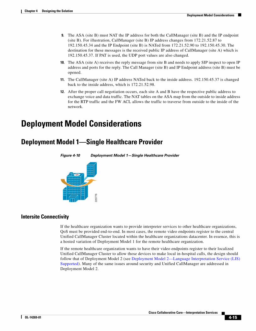
Chapter 4 Designing the SolutionDeployment Model Considerations
9. The ASA (site B) must NAT the IP address for both the CallManager (site B) and the IP endpoint (site B). For illustration, CallManager (site B) IP address changes from 172.21.52.87 to 192.150.45.34 and the IP Endpoint (site B) is NATed from 172.21.52.90 to 192.150.45.30. The destination for these messages is the received public IP address of CallManager (site A) which is 192.150.45.37. If PAT is used, the UDP port values are also changed.
10. The ASA (site A) receives the reply message from site B and needs to apply SIP inspect to open IP address and ports for the reply. The Call Manager (site B) and IP Endpoint address (site B) must be opened.
11. The CallManager (site A) IP address NATed back to the inside address. 192.150.45.37 is changed back to the inside address, which is 172.21.52.98.
12. After the proper call negotiation occurs, each site A and B have the respective public address to exchange voice and data traffic. The NAT tables on the ASA map from the outside to inside address for the RTP traffic and the FW ACL allows the traffic to traverse from outside to the inside of the network.
Deployment Model Considerations
Deployment Model 1—Single Healthcare Provider
Figure 4-10 Deployment Model 1—Single Healthcare Provider
Intersite Connectivity
If the healthcare organization wants to provide interpreter services to other healthcare organizations, QoS must be provided end-to-end. In most cases, the remote video endpoints register to the central Unified CallManager Cluster located within the healthcare organizations datacenter. In essence, this is a hosted variation of Deployment Model 1 for the remote healthcare organization.
If the remote healthcare organization wants to have their video endpoints register to their localized Unified CallManager Cluster to allow those devices to make local in-hospital calls, the design should follow that of Deployment Model 2 (see Deployment Model 2—Language Interpretation Service (LIS) Supported). Many of the same issues around security and Unified CallManager are addressed in Deployment Model 2.
2207
76
4-15Cisco Collaborative Care—Interpretation Services
OL-14269-01

Chapter 4 Designing the SolutionDeployment Model Considerations
Numbering Plan
Since Deployment Model 1 in its purest form does not require inbound calls, or outbound calls to an external location, the numbering plan needs only to conform to that which is in effect within the healthcare provider. However if the solution might be migrated to one of the other deployment models, careful planning should be done during the deployment of this phase of the implementation to prevent numbering planning issues from surfacing later. It is recommended that you examine the numbering plan recommendations found in the other deployment model sections.
Script Overview
For Deployment Model 1 (Single Healthcare Provider), the Unified Contact Center Express script logic must locate an available agent who has the highest skill level. Figure 4-11 provides a high-level overview of the logic flow that the DM1 script should handle.
Table 4-6 DM1 Device Registration
Hospital A Unified CallManager Hospital A UCCX
Agent Endpoints Yes Yes
Clinician Endpoints Yes No
4-16Cisco Collaborative Care—Interpretation Services
OL-14269-01

Chapter 4 Designing the SolutionDeployment Model Considerations
Figure 4-11 Script Logic Flow—Deployment Model 1
Additional logic can be added to the IVR script that permits the selection of the agent based on gender or other value-based metrics.
Suggested agent search order:
1. Interpreter available with language skill
2. Interpreter with preferred gender
3. If non-dedicated interpreter, one that can handle call with least impact to primary responsibility
Welcome caller,Inform of any legal items
Prompt user for languageselection (IVR or Web)
Confirm user selection(IVR Only)
Find agent with highestpriority for skill selected
Transfer call to highestavailable skilled agent
Mark call as answered,end script execution
End
Agentavailable? Yes
Agentavailable?
Call queued, play MOH “prompt”for 30 seconds and collect caller
IVR input
Yes
No
Did caller escalate call?If so, change priority to high.
Did caller request operator?If so, transfer call to operator.
Announce callersposition in hold queue
Start
No
2206
99
4-17Cisco Collaborative Care—Interpretation Services
OL-14269-01
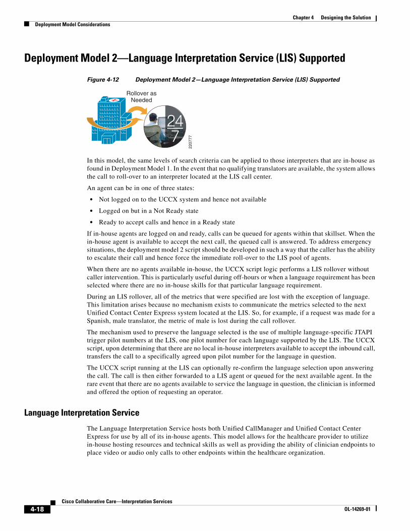
Chapter 4 Designing the SolutionDeployment Model Considerations
Deployment Model 2—Language Interpretation Service (LIS) Supported
Figure 4-12 Deployment Model 2—Language Interpretation Service (LIS) Supported
In this model, the same levels of search criteria can be applied to those interpreters that are in-house as found in Deployment Model 1. In the event that no qualifying translators are available, the system allows the call to roll-over to an interpreter located at the LIS call center.
An agent can be in one of three states:
• Not logged on to the UCCX system and hence not available
• Logged on but in a Not Ready state
• Ready to accept calls and hence in a Ready state
If in-house agents are logged on and ready, calls can be queued for agents within that skillset. When the in-house agent is available to accept the next call, the queued call is answered. To address emergency situations, the deployment model 2 script should be developed in such a way that the caller has the ability to escalate their call and hence force the immediate roll-over to the LIS pool of agents.
When there are no agents available in-house, the UCCX script logic performs a LIS rollover without caller intervention. This is particularly useful during off-hours or when a language requirement has been selected where there are no in-house skills for that particular language requirement.
During an LIS rollover, all of the metrics that were specified are lost with the exception of language. This limitation arises because no mechanism exists to communicate the metrics selected to the next Unified Contact Center Express system located at the LIS. So, for example, if a request was made for a Spanish, male translator, the metric of male is lost during the call rollover.
The mechanism used to preserve the language selected is the use of multiple language-specific JTAPI trigger pilot numbers at the LIS, one pilot number for each language supported by the LIS. The UCCX script, upon determining that there are no local in-house interpreters available to accept the inbound call, transfers the call to a specifically agreed upon pilot number for the language in question.
The UCCX script running at the LIS can optionally re-confirm the language selection upon answering the call. The call is then either forwarded to a LIS agent or queued for the next available agent. In the rare event that there are no agents available to service the language in question, the clinician is informed and offered the option of requesting an operator.
Language Interpretation Service
The Language Interpretation Service hosts both Unified CallManager and Unified Contact Center Express for use by all of its in-house agents. This model allows for the healthcare provider to utilize in-house hosting resources and technical skills as well as providing the ability of clinician endpoints to place video or audio only calls to other endpoints within the healthcare organization.
Rollover asNeeded
2207
77
4-18Cisco Collaborative Care—Interpretation Services
OL-14269-01

Chapter 4 Designing the SolutionDeployment Model Considerations
Hospital Services
For this deployment model, each healthcare provider hosts their own instance of Unified CallManager and Unified Contact Center Express. All endpoints within a given healthcare organization register with their own Unified CallManager cluster.
Changing LIS vendors is simplified in this deployment model and requires the following:
• WAN connectivity with QoS to new LIS
• Configuration of SIP trunks to new LIS
• Configuration of ASA firewall for SIP trunks and SIP inspect (if not already competed)
• Addition of Route-Patterns in Unified CallManager to direct calls to numbering plan of new LIS via SIP trunk
• Change of UCCX script logic to rollover to this LIS set of pre-defined language specific pilot numbers
Intersite Connectivity
Connectivity between CallManager clusters is accomplished through the use of SIP trunks. Call signaling between CallManager instances traverses these virtual trunks and permits the negotiation of calls between endpoints which are registered to different CallManagers. Furthermore, for security purposes, the SIP call signaling path is monitored in real time by the healthcare organization’s ASA firewall, providing dynamic connectivity between calling and called endpoints in a secure manner. Likewise, the ASA firewall located at the LIS edge monitors the SIP trunk for inbound calls and securely allow the calls to complete.
SIP Trunks
For configuration information of SIP trunks, see the Cisco Unified CallManager Administration Guide. When configuring SIP trunks between healthcare organizations or LISes that are behind a firewall performing NAT/PAT, it is important to use the externally-facing IP address of the CallManager as opposed to the actual IP address of the remote CallManager.
Numbering Plan
The numbering plan for endpoints should use one of two models. The first recommendation is to use the E.164 Numbering Plan that is in use in the local region. The second recommendation is the use of a numbering plan as assigned by the contracted LIS.
Table 4-7 DM2 Device Registration
Hospital A Unified CallManager
Hospital A UCCX via CAD or IPPA
LIS Unified CallManager
LIS UCCX via CAD or IPPA
Hospital A Agent Endpoints Yes Yes No No
Hospital A Clinician Endpoints
Yes N/A No N/A
LIS Agent Endpoints No No Yes Yes
4-19Cisco Collaborative Care—Interpretation Services
OL-14269-01
Chapter 4 Designing the SolutionDeployment Model Considerations
E.164 Numbering Plan
Each region has assigned numbering plans in accordance with the local telecommunications numbering scheme. Typically a healthcare provider has contracted with the local telephone service provider and has received a block of telephone numbers for use within the hospitals telephone network. A subset of these numbers can be assigned to clinicians and local agents to ensure uniqueness and unique call routing throughout the IP-based telephony network.
Some examples of E.164 based numbering plans are:
• European Telephony Numbering Space: http://www.etns.org/
• North American Numbering Plan Administration: http://www.nanpa.com/
• UK, Office of Communication: http://www.ofcom.org.uk/telecoms/ioi/numbers/
LIS Assigned Numbers
Assignment of private phone numbers for use by the clinicians and agents can be provided by the LIS. This method assures that there is no duplication of numbers between healthcare providers within the distributed IP telephony network.
The disadvantage of this approach is that it requires the re-numbering of agents and clinicians if and when the healthcare organization decides to change their contracted LIS.
Script Overview
For Deployment Model 2 the hospitals Unified Contact Center Express script logic must locate the most appropriately skilled in-house interpreter. In the event that one is found, but unavailable, the clinician is queued for the next available agent. In the event that the clinician needs immediate assistance, they may escalate the call, which initiates an immediate rollover to the LIS configured language specific pilot number.
Search Order
1. Locate most appropriately skilled interpreter using metrics supplied by clinician.
2. If there are no in-house translators ready to accept the call, rollover to LIS supplied pilot number for language specified.
4-20Cisco Collaborative Care—Interpretation Services
OL-14269-01

Chapter 4 Designing the SolutionDeployment Model Considerations
Figure 4-13 Script Logic Flow—Deployment Model 2
Welcome caller,Inform of any legal items
Prompt user for languageselection (IVR or Web)
Confirm user selection(IVR Only)
Find agent with highestpriority for skill selected
Transfer call to highestskilled in-house agent
Mark call as answered,end script execution
End
Agentavailable? Yes
Agentavailable?
Call queued, play MOH “prompt”for 30 seconds and collect caller
IVR input
Yes
No
Did caller escalate call?If so, transfer call to LISsupplied pilot number.
Did caller request operator?If so, transfer call to operator.
Announce callersposition in hold queue
Start
No
End
TransferCall
2207
00
.
Spanish : 555-555-0101ASL : 555-555-0102French : 555-555-0103German : 555-555-0104
.
.
And so on…
Language Interpretation ServiceSupplied Pilot Numbers
4-21Cisco Collaborative Care—Interpretation Services
OL-14269-01

Chapter 4 Designing the SolutionDeployment Model Considerations
Deployment Model 3—Collaborative Healthcare, LIS Supported
Figure 4-14 Deployment Model 3—Collaborative Healthcare, LIS Supported
Language Interpretation Service (LIS)
The LIS hosts both CallManager and Unified Contact Center Express for use by all agents. Agents at all participating hospital locations, along with the agents of the LIS, use the services of the LIS-supplied CallManager and Unified Contact Center Express systems. This provides the best design so that a hierarchical searching algorithm can be applied to inbound calls based on the unique business arrangements in effect between the LIS and a contracted healthcare provider. It also allows the LIS to provide rapid response to changes in call flows as the business arrangements change over time or as additional resources need to be brought to bear. Without this centralization, each collaborating hospitals’ staff would be required to be contacted when one of the associated collaborating hospitals wishes to make a change in the search logic.
Hospital Services
For this deployment model, each healthcare provider hosts their own instance of CallManager, but is not required to host an instance of Unified Contact Center Express. Each clinical endpoint within a given healthcare organization registers with their own CallManager deployment. This design permits the optional use of Unified Contact Center Express if desired, but at the same time allows connectivity between other locations also served by an existing CallManager deployment. Furthermore, it allows a more scalable and fault tolerant design, providing the hospital with the most flexible solution in the event that the organization wishes to change LIS.
Intersite Connectivity
Connectivity between CallManager clusters is accomplished through the use of SIP trunks. Call signaling between CallManager instances traverses these virtual trunks and permits the negotiation of calls between endpoints which are registered to different CallManagers. Furthermore, for security purposes, the SIP call signaling path is monitored in real time by the healthcare organization’s ASA
Use LISResources
Last
Use CollaboratingResources 2nd
Self 1st
2207
78
4-22Cisco Collaborative Care—Interpretation Services
OL-14269-01

Chapter 4 Designing the SolutionDeployment Model Considerations
firewall, providing dynamic connectivity between calling and called endpoints in a secure manner. Likewise, the ASA firewall located at the LIS edge monitors the SIP trunk for inbound calls and securely allows the calls to complete.
SIP Trunks
For configuration information of SIP trunks, see the Cisco Unified CallManager Administration Guide. When configuring SIP trunks between healthcare organizations or LISes that are behind a firewall performing NAT/PAT, it is important to use the externally-facing IP address of the CallManager as opposed to the actual IP address of the remote CallManager.
Numbering Plan
The numbering plan for endpoints should use one of two models. The first recommendation is to use the E.164 Numbering Plan that is in use in the local region. The second recommendation is the use of a numbering plan as assigned by the contracted LIS.
E.164 Numbering Plan
Each region has assigned numbering plans in accordance with the local telecommunications numbering scheme. Typically a healthcare provider has contracted with the local telephone service provider and has received a block of telephone numbers for use within the hospitals telephone network. A subset of these numbers can be assigned to clinicians and local agents to ensure uniqueness and unique call routing throughout the IP-based telephony network.
Some examples of E.164 based numbering plans are:
• European Telephony Numbering Space: http://www.etns.org/
• North American Numbering Plan Administration: http://www.nanpa.com/
• UK, Office of Communication: http://www.ofcom.org.uk/telecoms/ioi/numbers/
LIS Assigned Numbers
Assignment of private phone numbers for use by the clinicians and agents can be provided by the LIS. This method assures that there is no duplication of numbers between healthcare providers within the distributed IP telephony network.
The disadvantage of this approach is that it requires the re-numbering of agents and clinicians if and when the healthcare organization decides to change their contracted LIS.
Table 4-8 DM3 Device Registration
Hospital A CallManager
Hospital B CallManager
LIS CallManager
LIS UCCX via CAD or IPPA
Hospital A Agent Endpoints No No Yes Yes
Hospital A Clinician Endpoints Yes No No No
Hospital B Agent Endpoints No No Yes Yes
Hospital B Clinician Endpoints No Yes No No
LIS Agent Endpoints No No Yes Yes
4-23Cisco Collaborative Care—Interpretation Services
OL-14269-01

Chapter 4 Designing the SolutionDeployment Model Considerations
Script Overview
For Deployment Model 3 (Collaborative Healthcare, LIS Supported), the Unified Contact Center Express script logic must identify the caller in order to determine the correct hierarchical search criteria to use. Within DM3, the goal of the script is to locate an interpreter that is:
1. Local to the caller’s healthcare organization
2. An employee of an associated or collaborative healthcare organization
3. At a Language Interpretation Service
Search Order
1. Interpreter associated to healthcare organization requesting service.
2. Interpreter whose organization has a collaborative agreement with healthcare organization requesting service.
3. Interpreter which is an employee of the LIS.
To begin the agent selection search process, it is first necessary to determine the proper identity of a caller. There are three methods that can be used in an IVR (DTMF entry) script. Each is described below along with any advantages and disadvantages.
IVR caller identification methods:
• Ask caller to input their Healthcare Organization Code.
– Disadvantage—Cumbersome to the caller and prone to error.
– Advantages—Quick to implement with little script change.
• Provide each Healthcare Organization with their own pilot number.
– Disadvantages—Possible cost item if using E.164 phone numbers, inaccurate if healthcare provider dials wrong number (could be blocked or redirected to a specific number by originating CallManager).
– Advantages—Seamless to caller, customizable in healthcare provider’s CallManager.
• Use the caller’s telephone number (assuming a consistent numbering plan) to identify the caller’s parent healthcare organization.
– Disadvantages—Complete list of source numbers may not be obtainable, duplicate source phone number could cause incorrect assumption if not using real E.164 phone numbers.
– Advantages—Enforces use of a unique numbering plan.
Web-Based Caller Identification Methods
If using a web interface to collect caller information and perform a callback, the information can be passed as part of the web page variables that are returned to Unified Contact Center Express as part of the http trigger configuration. For billing purposes, it is not recommended to permit the clinician to choose which healthcare provider to select, as selecting the wrong one would cause the incorrect search logic to be invoked.
Regardless of the method used (Web or IVR), the UCCX Script must first search for the an interpreter for the language specified, for an agent associated with the healthcare provider. Each healthcare organization needs to have a prefix that is appended to the name of the skill being searched for. So for example, in the event of a caller from Hospital A looking for Spanish, the Skill and CSQ (Contact
4-24Cisco Collaborative Care—Interpretation Services
OL-14269-01

Chapter 4 Designing the SolutionDeployment Model Considerations
Service Queue) names would be HospA-Spanish. For Hospital B Spanish the CSQ and Skill names would be HospB-Spanish. The skills are then associated with their corresponding CSQ. This approach continues for hospital C, D, etc.
When an Language Interpreter agent for hospital A is configured in Unified Contact Center Express, they are assigned the proper HospA-******* skills. In our example that would be HospA-Spanish with a skill priority of 7. The priority given for these Hospital-A agents would be given a higher priority then that of collaborating hospital agents. In our example, if Hospital A and B choose to pool their spanish translators, the Hospital A Spanish speaking agents would be assigned as shown in Table 4-9.
When the script identifies the clinician requesting service as belonging to Hospital A, it begins looking for the highest ranking agent with the HospA + Spanish skill first. If one is found to be available, the call is routed to that agent. In this case, this would be a Spanish speaking agent who is an employee of Hospital A. This selection provides access to an agent at the lowest possible cost, or A-Agent1.
In the event that there are no high priority (7) HospA-Spanish agents available, it searches automatically for the next highest ranking agent having the HospA-Spanish with a priority of (5). This selection represents the next lowest cost option, that being B-Agent1.
If there are no Hospital-affiliated Spanish interpretation agents available, the algorithm automatically selects the next highest ranking agent, or LIS-Agent1 with a priority of 3.
Table 4-9 Assignments
Healthcare Organization Agent Name Skill 1 / Priority Skill 2 / Priority
Hospital A A-Agent1 HospA-Spanish / 7 HospB-Spanish / 5
Hospital B B-Agent1 HospA-Spanish / 5 HospB-Spanish / 7
LIS LIS-Agent1 HospA-Spanish / 3 HospB-Spanish / 3
4-25Cisco Collaborative Care—Interpretation Services
OL-14269-01

Chapter 4 Designing the SolutionUnified Communication Considerations
Figure 4-15 Script Logic Flow—Deployment Model 3
Unified Communication ConsiderationsCisco Unified Communications has many design factors to consider in the deployment of interpretations services. These considerations should be factored into the overall Unified Communication designs for a hospital network. The focus on these designs are specific to the enablement of the video-based endpoints and the Contact Center applications.
IP Endpoint SelectionThe IP endpoints used for Collaborative Care Interpretation Services are primarily focused on video-based endpoints that fulfill a specific technical criteria.
The primary selection for the video endpoints is:
• Polycom PVX—This is a H.323-based softphone running as a PC Application. The video and speaker phone functions are dependent on the camera and speakerphone bundled with Polycom PVX.
• Polycom VSX-3000—A SCCP hardphone with a built-in LCD monitor.
Welcome caller,Inform of any legal items
Prompt user for languageselection (IVR or Web)
Confirm user selection(IVR Only)
Find agent with highestpriority for skill selected
Transfer call to highestavailable skilled agent
Mark call as answered,end script execution
End
Agentavailable? Yes
Agentavailable?
Call queued, play MOH “prompt”for 30 seconds and collect caller
IVR input
Yes
No
Did caller escalate call?If so, change priority to high.
Did caller request operator?If so, transfer call to operator.
Announce callersposition in hold queue
Start
No
Determine caller identityfor “best” agent searching
2207
01
4-26Cisco Collaborative Care—Interpretation Services
OL-14269-01

Chapter 4 Designing the SolutionUnified Communication Considerations
• Polycom VSX-5000—A SCCP hardphone without a built-in monitor. An additional XGA monitor or television is used as the display device.
• Tandberg T1000 MXP—A SCCP hardphone with a built-in LCD monitor.
• Cisco 7985—A SCCP hardphone with a built-in LCD monitor.
The functionality shown below provided the best experience for the interpretation session:
• Video resolution for the camera and display at CIF (352x288) resolution that can capture and display video at 25 frames per second (fps) or better.
• Video Codec—H.264 MPEG4 Part 10 provides the best balance of video compression and video quality.
• Full screen video display is standard by default on most endpoints. The PC application also supports the ability to expand to full screen and allow for resizable window screen size.
• Picture-in-picture (PiP) to show the remote location at full screen and to show the local location in a small PiP screen.
• Supplementary voice services—Key functions include transfer, hold, and call park for voice and video.
Chapter 3, “Solution Features and Components” outlines the various endpoints tested with this solution to ensure its ability to meet the technical criteria.
While video is a key component for sessions, clear voice quality is also critical to a successful interpretation. The choice of G.722 voice codec provides excellent voice quality. In the CM 5.x SRND, there are recommendations for designing the network for voice and video quality. Specific factors to consider for the endpoint to provide voice to this applications include:
• Jitter buffers—Endpoint should support dynamic jitter buffers to process received voice packets that might arrive across the network at variable rates. To provide a smooth voice playback the endpoint should have a buffer to conceal any variable rates of voice packet arrival.
• Codec supported—To ensure capability with a variety of IP-based voice endpoints that may be deployed, the phone should support other common codec such as G.711 and G.729.
Other Considerations
• Camera—The camera used to capture the video is built into the majority of the endpoints with the exception of the PC application (Polycom PVX), which uses USB-based video cameras. The cameras have specifications listed in the data sheet for each endpoint type. The functionality of the camera that may be important to the call sessions are:
– Field of view—Defines the extent of the observable scene that can be captured at a given time as defined by angles. A common field of view ranges from 45-60 degrees, angles that can be defined in terms of both vertical view and horizontal view. This factor may be important based on the portion of a person’s body that must be captured for an Sign Language interpretation. ASL recommends that the interpreter be displayed from waist up to provide the best experience.
– Pan—Defines the horizontal movement of a video camera to adjust the position that a camera captures the images.
– Tilt—Defines the vertical movement of a video camera to adjust the position that a camera captures the images.
– Zoom (local/remote)—Defines the ability for a camera lens to vary the focal length that a camera uses to capture the image. This function may be important during a consultation to zoom into a specific area for the remote party to view and provide a better description. Most of the video endpoints provide local zoom; that is, the caller can control only their own camera. The
4-27Cisco Collaborative Care—Interpretation Services
OL-14269-01

Chapter 4 Designing the SolutionUnified Communication Considerations
Polycom VSX-5000 provides the ability for the destination party to control the camera via a web interface of the originating party. This function can be used for a interpretation agent using a Cisco 7985 to control the clinician/patient video endpoint when using a VSX-5000.
– White balance—In many examination rooms, florescent lighting is used. Video captured in this environment may have blurry images or alternative color temperatures. To help offset this, white balance focuses on identifying images in a room that are white. Based on this baseline, the camera can calculate the difference between the color temperature of the object that is white and that of the object that is of a different color. For images that do not perform a white balance, the image may come across as yellow/orange in color.
– Focal length—Determines the distance from the camera that defines the focal point of an image. This function may work in conjunction with the zoom of the camera to get the best image of a person at the right size. This consideration may become important for a patient that may not be easily maneuverable during a consultation.
This design guide does not examine the details of each camera type and specify which to use for the application. Much of this is preference and maps to the specific environment used for the interpretation service. However, these considerations should be evaluated when considering the deployment of the IP video endpoint.
For selection of the Polycom PVX USB Camera, refer to Polycoms document located at:
http://www.polycom.com/common/pw_cmp_updateDocKeywords/0,1687,4556,00.pdf
• Video display size—Defines the size display screen that is available for the endpoint. The Polycom PVX is a PC application, therefore the screen size depends on the PC. Additionally, the Polycom VSX 5000 requires a external monitor or television which determines the screen size.
• CTI integration—There are two methods of integration for an agent in this solution. Using CAD on a PC provides the broadest range of functions to an interpretation agent, but requires a PC to run the application. The second form of integration is through a XML application that runs on the Cisco 7985. The Cisco 7985 is the only endpoint that supports this functionality.
• IP bandwidth—The data rates for video vary and each endpoint was measured for the amount of IP bandwidth generated under three different conditions (no movement, low movement, and high movement). The capacity design section provides design information on management of IP bandwidth.
• Microphone and echo cancellation—The majority of the endpoints are phones so they have built-in microphones supported by the speaker phone functionality. Many of the cameras also have a built-in microphone and echo cancellation function.
For selection of the cameras with built-in microphones, refer to:
http://www.polycom.com/common/pw_cmp_updateDocKeywords/0,1687,4556,00.pdf
If it is desirable to have a dedicated microphone and echo cancellation, Polycom has a USB-based speakerphone that can be installed on the PC.
• Form factor—The construction of the clinician and patient endpoint needs to be mobile and easy to access. This solution does not provide a pre-built solution for carts, but Polycom and Tandberg have solutions to address the form factor for these mobile video endpoints.
Endpoints that support voice only are not covered in detail. For the interpretation service that requires only voice, Chapter 3, “Solution Features and Components” covers several Cisco IP-based voice endpoints that support voice-only functionality.
4-28Cisco Collaborative Care—Interpretation Services
OL-14269-01

Chapter 4 Designing the SolutionUnified Communication Considerations
IP Video Endpoint MixturesThe key determining factor for the type of IP video endpoint that an agent can use in this solution is the interaction with the Cisco Agent Desktop or IPPA XML application. Either of these applications are critical for a agent desktop to interface with Cisco Unified Contact Center Express. The Cisco 7985 is the only IP video endpoint that is supported with CAD or IPPA.
This solution has been validated to work with all IP video endpoints listed in Chapter 3, “Solution Features and Components” and utilizes the full capabilities of this solution.
Other Cisco IP voice endpoints listed in Chapter 3, “Solution Features and Components” can be used as the agent phone or the clinician phone. These phones have full interworking with CAD or IPPA.
Call Signalling ComponentsCallManager support several call signaling protocols and supports protocol translation between endpoints in a non-homogeneous environment. This section outlines the different protocols used by the solution and the interactions between protocols.
In addition to the many functions handled by the call signaling, the specific functions that enable the video consultation are:
• G.722 voice negotiation and alternative voice codec negotiation to G.711 and G.729 when necessary
• H.264 video codec negotiation
• DTMF negotiation for out-of-band DTMF
SCCP is the primary protocol used by the majority of the endpoints to negotiate the bearer functionality and call routing for the IP video and voice calls.
H.323 is the protocol used by the PC application endpoint, Polycom PVX.
SIP is the protocol used between CallManager clusters for calls that traverse one domain to another domain. SIP is also used for voice calls that get routed to the PSTN.
JTAPI is the protocol used between CallManager to Unified Contact Center Express. This interaction is required for all calls that must route and find an interpretation agent.
Table 4-10 Call Signaling Protocol Used in Collaborative Care
SCCP SIP H.323 JTAPI
CallManager X X X X
Unified Contact Center Express
X
Cisco 7985 X X (with XML App)
Polycom PVX X
Polycom VSX-3000 X
Polycom VSX-5000 X
Tandberg T1000 MXP X
Cisco Agent Desktop X
PSTN Gateway X
Cisco Gatekeeper X
4-29Cisco Collaborative Care—Interpretation Services
OL-14269-01

Chapter 4 Designing the SolutionUnified Communication Considerations
Protocol Translations
Based on the various protocol used, CallManager translates between protocols when the following scenarios are encountered:
• H.323-SIP—Calls made from Polycom PVX that need to route across to another CallManager cluster or calls that are routed to the PSTN gateway.
• H.323-SCCP—Calls made from Polycom PVX that terminate to a Cisco 7985.
• SCCP-SIP—Calls made from all other IP endpoint types used in Collaborative Care that route to another CallManager cluster or route to the PSTN Gateway.
• H.323 or SCCP or SIP-JTAPI—Any calls that are determined to route to Unified Contact Center Express use CallManager to translate from the protocol used by the endpoint, PSTN gateway, or another CallManager cluster to the protocol used to communicate with Unified Contact Center Express.
SIP TrunkCommunication between CallManager Clusters are required for Deployment Model 2 and 3. The primary condition is when communication occurs between two different organization which can be hospital to hospital or hospital to LIS. The connectivity between these two organizations still occurs via IP connections. Provisioning between two CallManager clusters must be defined by each CallManager cluster to build this connection.
• Dial plans should be designed with a fully-qualified E.164 address. The primary route for this connection is sent via a SIP trunk route versus a PSTN route. The SIP trunk route is required to maintain IP connection since the video calls can only be sent via IP, not over PSTN connections.
• Other forms of inter-cluster CallManager connectivity is possible, but H.264 is the primary video codec required. Currently only SIP trunk between CallManager clusters supports the negotiation of H.264 video. If other protocols are used, the H.264 attributes are lost. H.323 currently supports other forms of video such as H.263. Since the endpoints are configured for H.264, calls using H.323 trunks may receive only voice between to two IP video endpoints.
• SIP trunk also enables the G.722 codec between intercluster trunks.
• The SIP trunk should be associated with a region that is uniquely defined to support G.722 codec and at least 768Kpbs of video.
• SIP trunk is also used as the path to interconnect calls with the traditional PSTN for voice only. The PSTN gateways are defined as SIP trunks.
• Each CallManager cluster can directly point to the other CallManagers within the consortium that shares interpretation services. However, if the number of hospitals grows, the design should include a DNS server that all CallManager SIP trunk routes would use to resolve address of other CallManager clusters. This DNS server would be owned and operated by the LIS that is overseeing the interconnections between hospitals.
For an overall approach to designing SIP trunks for CallManager to CallManager communication or for PSTN connections, refer to the section Cisco Unified CallManager Trunks in the Call Manager 5.x SRND.
4-30Cisco Collaborative Care—Interpretation Services
OL-14269-01

Chapter 4 Designing the SolutionUnified Communication Considerations
Cisco IOS GatekeeperThe Cisco IOS Gatekeeper is an H.323 Gatekeeper function that runs natively on IOS images. From a design perspective, there are some extra considerations that is required to add H.323 endpoints into the system:
• The IP video endpoint registers to the Cisco IOS Gatekeeper instead of registering to the CallManager as endpoints running SCCP would do. If authentication is required for the registration, this authentication is done via the Gatekeeper authentication capabilities with backend servers. Even with the registration being handled by the Gatekeeper, the CallManager must define an instance for each H.323 device endpoint on the CallManager system. The CallManager registers with the IOS Gatekeeper to keep track of the H.323 devices.
• From the perspective of the IP video endpoint that is running H.323, it is responsible for defining capabilities for voice bearer and video capabilities use. The H.323 model is different than the SCCP model in that the provisioning of these capabilities is done on the endpoint, where as in SCCP the definitions are performed by the CallManager centrally. This distributed configuration for H.323 endpoints requires stricter control of the endpoints for PVX configurations.
• The dialplan management for H.323 endpoints are split between the CallManager and IOS Gatekeeper. For this solution, all endpoints send an Admission Request message to the IOS Gatekeeper. Since these calls are targeted towards a CTI port, the IOS gatekeeper resolves all these calls to the IP address of CallManager. CallManager is then responsible for routing the calls further into the system based on the call dial plan configured in its system. The IOS gatekeeper only has responsibility for registration and routing calls to the appropriate CallManager.
Bearer Factors
Voice Codec
Voice packets are encoding using the G.722 codec as the preferred codec. This codec is an ITU-T standards-based wideband speech codec meant for low rate audio encoding below 64 kbit/s. This codec offers sampling rates at 16kHz, which is double that of traditional telephony interfaces, offering an improvement in speech quality over other forms of codec. All endpoints used in this solution can support signaling negotiation and voice encoding using G.722.
Video Codec—H.264
H.264 received Final Draft status on March 28, 2003 by the Joint Video Team (JVT), a committee of Moving Picture Experts Group (MPEG) and International Standards Organization/International Telecommunications Union (ISO/ITU). Final ratification of H.264 by the ITU happened on May 30th. H.264 is also known as MPEG 4 part 10.
A new video encoding and decoding scheme has been added as a standard under the ITU’s H.320 and H.323 umbrella for low bandwidth video-conferencing over ISDN and IP. This new codec provides near broadcast quality video, in part by supporting 60 fields per second (30 full frames) and an advanced method of reducing, if not eliminating, the pixilation we often see when using H.261 or H.263 video codecs when there is a lot of motion or scene changes.
The ITU, along with Internet streaming and other standards organizations, formed a Joint Video Team (JVT) to come up with a common format codec for both MPEG users and video-conferencing users. The resulting new standard codec is know as JVT/AVC (Advanced Video Coder). It is known by the MPEG industry at MPEG 2 Part 10 and by the ITU and the video-conferencing industry as H.264.
4-31Cisco Collaborative Care—Interpretation Services
OL-14269-01

Chapter 4 Designing the SolutionUnified Communication Considerations
H.263, the codec in use the past several years, supports 30 frames per second video. In television video, each frame has two interlaced fields. Prior to compressing, one field is tossed aside (every other line) by H.263 to produce 30 frames per second video at the narrow bandwidths used in video-conferencing. Thus, each compressed video frame corresponds to only one of two input video fields. The result is a somewhat lower video resolution quality of 352x288 pixels or video pixilation.
The H.264 protocol improves the video resolution quality in the H.323 protocol suite by encoding and transmitting two interlaced fields for each frame (that is 30 frames per second and 60 fields per second, instead of only 30 fields per second of H.263). This process allows us to present decoded video that is much more fluid and lifelike. The result of this enhancement is a substantially higher resolution quality that approaches or matches MPEG-2 quality at a 64% lower bandwidth cost.
H.264 also handles the encoding of the pixel blocks more efficiently than H.263, practically eliminating the tiling or pixilation seen on video conferences today when there is a scene change or a lot of motion.
The ITU-T H.264 standard and the ISO/IEC MPEG-4 Part 10 standard (formally, ISO/IEC 14496-10) are technically identical. The final drafting work on the first version of the standard was completed in May of 2003.
DTMF—Out of Band
Dual Tone Multi-Frequency (DTMF) is the method by which keypad presses are transferred between one device to another device. Typically the device originating the DTMF is the IP video endpoint. The recipient of the DTMF tone is the IVR system, but in this solution the CallManager functions as a proxy for the DTMF tones. The IVR system in Unified Contact Center Express does not accept inband DTMF tones that are transmitted through the G.722 encoding of the voice packet nor does it receive packets sent through RFC2833 NTE encoding, which are uniquely labeled RTP, packets to send DTMF.
For this solution, due to the requirement to select through menus to find the right interpretation agent in the IVR system, reliable DTMF relay through the IP network is critical.
Therefore the design of the DTMF through the system is for an endpoint or a CallManager cluster to send DTMF through out-of-band signaling paths that are received by CallManager. CallManager is responsible for translating this DTMF tone received via the call signaling path and sending that DTMF tone through the JTAPI interface to the Unified Contact Center Express system.
To support this for all endpoint variations, the following methods are used for each protocol type. The individual endpoints must be aware a button press has been made on the endpoint after the call is in a connected state. The phone then encodes the DTMF inside the respective call signaling messages.
• SCCP uses SCCP out-of-band DTMF that is sent inside of a KeypadButtonMessage. The actual button pressed is expressed inside a parameter called KeypadButton.
• SIP uses an out-of-band DTMF transmission technique by sending an INFO message. Inside this message is a text-based encoding of the DTMF that was pressed.
• H.323 has two different out-of-band DTMF methods. The method used for this solution is for a h245-alphanumeric message to be sent. An ASN.1 encoding of the message provides the keypad button that was pressed. The other method called h245-signal provides an additional piece of information for the duration of the button press. H245-signal is not required for this solution.
Voice and Voice—Video During call
At different times during the call setup, the clinician/patient dialing into the system receives either voice only or voice and video. When a call is made into the pilot number to enter the IVR menu selection for the interpretation agent, the call voice bearer stream connects between the originating endpoint and the IVR system in the Contact Center. At that time, only voice is connected.
4-32Cisco Collaborative Care—Interpretation Services
OL-14269-01

Chapter 4 Designing the SolutionUnified Communication Considerations
Once a clinician has walked through the menu selection, an interpretation agent may not be immediately available. In this case, the caller is placed in a waiting queue on the Unified Contact Center Express and Music on Hold may be played back. Again in this condition only voice is negotiated.
Only when an agent is determined to be available is the call be routed to the actual endpoint. In this case, the capabilities of the agent are determined. If the agent is using a Cisco 7985 IP video phone, the caller is able to negotiate a voice and video stream. If either party does not have video capabilities, the call remains voice only.
If at anytime the interpretation agent transfers the call to another device that does not have video capability, the call fallbacks to voice-only. Alternatively, if the call begins with only a voice agent and the call gets transferred to a Cisco 7985-enabled agent, the call upgrades to voice and video.
CallManager Deployment ModelsFor this solution there are two types of Call Manager deployment models that may be used:
• Single site
• Multisite WAN with central-site model
In the single site model, all components of the call control, endpoints, and gateways reside on a single site. If another site is required, each site needs their own call control system onsite. This deployment model structure is used for large hospital systems that each demand their own system. Also in the deployment models where there are B2B relationships, each domain would deploy and manage their own CallManager.
For some large site deployment models and the LIS model where the location of phones for the clinician or agent may not be on the same site as the CallManager, the multisite WAN with central-site model should be used. Having a well-designed QoS model is important for this deployment model to ensure the SLAs for the call signaling and bearer data are maintained.
Other deployment models, such as multisite WAN with distributed call process and clustering over the IP WAN, are not recommended due to interactions with Unified Contact Center Express.
Admission ControlIn each of the deployment models, there is a requirement to support multiple sites. The site-to-site connectivity introduces a potential for bandwidth constraints on the network to deliver voice and video traffic between sites. Each deployment model may introduce different constraints on the need for admission control.
The method described in this section utilizes a more basic approach to admission control using topology-unaware call admission control. This approach uses statically defined regions and locations on CallManager that are effective for simple data networks such as hub-and-spoke or simple MPLS VPN networks. For data networks with a more complex design, the CM 5.x SRND provides design approaches to using topology-aware call admission control with the use of RSVP.
Regions are defined on CallManager to specify a logical group of devices that have common attributes for video and voice. A logical grouping could be that all phone types that are video enabled be associated within the same region for a CallManager cluster. The latter method is the recommend method to simplify the region. All phones with video capabilities should be defined in the video region. IP phones with only voice capability should not be assigned to this video region. When devices are created, the device can be associated to a region.
4-33Cisco Collaborative Care—Interpretation Services
OL-14269-01

Chapter 4 Designing the SolutionUnified Communication Considerations
In the region a bandwidth setting is defined for the maximum usage per call for the audio and video portions of the call. The Audio Codec field defines the maximum bit-rate allowed for audio-only calls as well as for the audio channel in video calls. For instance, if you set the Audio Codec for a region to G.722, Cisco Unified CallManager allocates 64 kbps as the maximum bandwidth allowed for the audio channel for that region. The Video Bandwidth field defines the maximum bit-rate allowed for the video channel of the call. If the video bandwidth for the endpoints specifications include the audio bandwidth, then the video bandwidth should be defined as the sum of both video and audio.
Locations are defined to allow a group of devices that belong to a specific location to share a resource pool in a centralized deployment model. These locations defined in CallManager are logical locations that can be associated to physical locations, such as a branch office or a corporate location. When location A exchanges a call with a location B, the resources defined for each location are queried to determine the available resource remaining. The resources are defined by the audio resources and the video resources. An audio resource is defined by the RTP payload plus the IP overhead for the call. For a G.722 call, that value should be 80kpbs. The audio resource should then be the total number of allowed calls that enter and exit the region times the 80kpbs. A video resource is defined by the audio plus video bandwidth for the call. Defining 768 kbps for the call is enough for both the video and audio bandwidth generated by these IP video endpoints. If the resolution of these calls are adjusted, then adjust the sizing accordingly. The video bandwidth is then defined by the 768 kbps times the number of calls allowed to flow from one region to another region.
The total bandwidth should be derived from the speed of the link that connects that location and the percentage of that link that would be allocated for voice and video traffic. From that number, the amount of bandwidth resources should be partitioned between the expected number of voice and voice and video calls.
Note Calls that are made within the same region do not take resources away from the resource pool defined for that specific location. Only calls that traverse from one location to another location are decremented from the resource pool.
• DM1—In a hospital deployment where multiple sites are supported by a centralized CallManager, the links for the site-to-site private WAN can be a congestion point. In DM1, each site should group their endpoints into a unique location.
• DM2—This model includes the same constraints as DM1. To handle the rollover connection between the hospital and the affiliated hospital or the LIS that is connected via a SIP trunk, the SIP trunk should be defined in a different location.
• DM3—This model is limited to the control defined on the CallManager at the LIS. This model is only aware of the agents that are distributed across the various sites. All the agents are grouped into a location that is at a specific location. A SIP trunk that connects to that location is also placed in the same location group. If a call is made between an agent and clinician at the same hospital, placing the SIP trunk and agent in the same location does not decrement resources from that location’s bandwidth pool. However once a call is made from to an agent at location A and a
Table 4-11 Resource Definitions for Region and Locations
Setting Voice Bandwidth Video Bandwidth
Audio Region G.722 none
Video Region G.722 768 kbps
Video Location 80 kbps (G.722) per call * X number of calls
768kbps (H.264 video used for this solution) per call * Y number of calls
4-34Cisco Collaborative Care—Interpretation Services
OL-14269-01

Chapter 4 Designing the SolutionUnified Contact Center Express (UCCX) Considerations
clinician call that arrives through a SIP trunk at location B, the call resource is decremented from the resource pool of the CallManager residing at LIS. In this model, the centralized CallManager at the LIS is responsible for the resource management of the site-to-site connections.
Note The bandwidth should reflect the resource constrained link that connects phones from site A to site B.
As the video bandwidth setting is significantly greater than the voice bandwidth, there may be situations where there is less than 768kbps total aggregate bandwidth remaining in the locations resource pool. In these cases, an attempted video call may not have enough resources, but an audio call will. If that is the case, the field Retry Video call as Audio should be selected such that the video-attempted call can be attempted as a voice-only call.
Note If there are a significant number of situations where this condition occurs, the link speed for this particular location should be upgraded.
Media Termination PointMedia termination point is a function that allows two legs of a call to be bridged together such that they can be handled as two independent legs of a call. MTPs are useful for scenarios such as allowing a H.323 client to receive the treatment of a supplementary voice service such as call transfer. Two flavors of MTP exist, software-based and hardware-based.
CallManager 5.x supports a hardware-based pass through of video codec. However since the endpoints are configured to use G.722, there is no requirement to bridge these calls together. Therefore, the recommendation is to not apply MTP to any of the endpoints used for video calls.
PSTN ConnectionsPhones used by the clinician or agent may at times require traditional PSTN service. The use of SIP to handle intersite calls is also used to manage PSTN Gateways to interconnect with traditional PSTN networks. Depending on the size of the site and number of connections, a range of PSTN connections, such as FXO, ISDN, and PRI links, could be used. A range of IOS devices, including ISRs, can be used as the PSTN gateway. The PSTN Gateway registers with the CallManager as a SIP Gateway. Detailed designs for PSTN connections can be found in the CM 5.x SRND.
Calls that arrive from the PSTN into the Contact Center for interpretation services are feasible as well. However, these connections are limited to voice-only connections. The PSTN gateway is responsible for the voice encoding from the PSTN network to the IP network using G.722 and handling the DTMF signals received to be set via SIP INFO messages to CallManager.
Unified Contact Center Express (UCCX) ConsiderationsCisco Unified Contact Center Express 4.5 is the first version of Unified Contact Center Express that is compatible with Cisco Unified CallManager 5.x, which is a Linux-based appliance. Unified Contact Center Express continues to be a Windows 2000-based product and therefore cannot be installed on the same server which is used for CallManager. There are a number of differences between Unified Contact Center Express version 4.5 and prior releases.
4-35Cisco Collaborative Care—Interpretation Services
OL-14269-01

Chapter 4 Designing the SolutionUnified Contact Center Express (UCCX) Considerations
RedundancyRedundancy is achieved only through the use of a cold standby server. Multi-server redundancy similar to that found in previous releases of Unified Contact Center Express will be available in an upcoming Unified Contact Center Express release. If redundancy is desired, it is recommended to configure one Unified Contact Center Express 4.5 platform on an MCS server with mirrored drives. Once the UCCX server is operational, remove one of the mirrored drives and place it into an identical MCS server which is in a powered-off state.
During a failure of the currently-active Unified Contact Center Express server, enabling the second server restores connectivity. During this time, any calls made to the pilot numbers do not complete. It is therefore critical that the configurations of both the active and cold standby Unified Contact Center Express servers are kept in synchronization. If they are not, bringing the cold server online complicates and delays service restoration during a recovery failure.
UCCX CapabilitiesThe Cisco Unified Contact Center Express capabilities are dependant on the type of Media Convergence Server being used. Table 4-12 highlights some of these requirements for each MCS server considered for use in this solution. UCCX is capable of running on smaller MCS platforms, but for scalability only two are considered feasible. Consult the UCCX product guide for more information on MCS server capabilities.
UCCX Usage Reports and BillingThe UCCX system includes a component called Historical Reports which provides comprehensive information about the call usage based on a number of reporting criteria. These reports are useful when trying to determine usage information and include information as shown below Each of these reports have sub categories resulting a a total of 138 different report types.
• Abandoned Call Detail Activity
• Aborted and Rejected Call Detail
• Agent Call Summary
• Agent Detail Report
• Agent Login & Logout Activity
• Agent Not Ready Reason Code Summary
Table 4-12 Capabilities
7845 Dual Processor 7835 Single Processor
Total number of Skills system wide 150 150
Total number of skills per agent 50 50
Total number of Customer Service Queues (CSQs)
100 25
Number of Logged in agents 300 75
Number of Logged in Supervisors 32 10
Calls in Queue status 300 150
4-36Cisco Collaborative Care—Interpretation Services
OL-14269-01

Chapter 4 Designing the SolutionUnified Contact Center Express (UCCX) Considerations
• Agent Sate Summary
• Agent Summary
• Application Performance Analysis
• Application Summary
• Call Custom Variables
• Called Number Summary
• Common Skill Contact (CSQ) Activity
• CSQ Agent Summary
• Detailed Call by Call
• Detailed Call & CSQ Agent
• Priority Summary Activity
• Remote Monitoring Detail
• Traffic Analysis
By using the standard reports included with UCCX, the administrator can quickly determine patterns of usage and determine a usage baseline. Once determined, additional language interpreters with the skills needed to address the demand trends can be brought onboard.
These reports work very well for Deployment Model 1 and 2 from the perspective of the healthcare organization. For the Language Interpretation Service however, the ability to create custom reports that can be used for billing requires additional development.
Access to the historical reporting function is achieved by using the Cisco CRS Historical Reports plug-in found on the UCCX plug-ins page shown in Figure 4-16. Once this plug-in is installed, the user can generate a number of reports for a supplied date range. Additionally, these reports can then be scheduled for delivery in a file format or automatically printed to a printer on a scheduled basis. This is accomplished through the use of a Report Scheduler task that is started on the workstation. Once running in the system tray, reports are automatically generated in the background as specified in the report schedule for this user.
Figure 4-16 Cisco CSR Historical Records
4-37Cisco Collaborative Care—Interpretation Services
OL-14269-01

Chapter 4 Designing the SolutionUnified Contact Center Express (UCCX) Considerations
Custom Reports
If the LIS has an existing billing system, the call records can be exported to an external database which the existing billing system can utilize to produce the necessary output. Detailed instructions for exporting the historical database are found in the Cisco Customer Response Solutions 4.5(1) Historical Reporting Administrator and Developer Guide found on the Cisco Connection Online website.
UCCX has the ability to allow the use of Crystal Reports, a generally available 3rd-party application to generate customized reports directly from the Historical Database. Crystal Reports version 8.5 or 10 (professional or developer edition) is required for compatibility reasons. Access to the UCCX Historical Database is accomplished through the use of the ODBC (Open Database Connectivity) protocol.
A useful technique to assist in the creation of custom reports is to include provisions in the IVR script that uses custom variables that are included in the call records which are written to the historical database. One such use that may assist the LIS in the report creation is the use of custom variable that is the unique name of the healthcare organization. When an inbound call is placed from Hospital A for example, creating a healthcare organization variable which contains HOSP-A may be useful when creating a billing report for Hospital A.
Likewise, custom variables can be also used to identify the agent who accepted the call. This is useful when deployment model 3 is used by a LIS and pooling of healthcare provider resources are used within the solution. In such collaborative settings, identifying the caller and agents affiliation within the script will greatly simplify the report generation process.
IP Phone Agent (IPPA) Support
The Cisco IP Phone Agent (IPPA) provides the agent with limited functionality to logon to the Unified Contact Center Express system. Once logged into the system, the agent can change their state from Not-Ready to Ready. When in Ready state, the agent is routed calls based on their configured skill sets.
The availability of IPPA and the Cisco Agent Desktop is limited to the Cisco SCCP-based endpoints shown in Table 4-13.
Table 4-13 Cisco SCCP-Based Endpoint
Cisco Endpoint IPPA Support CAD Support
7912 Yes Yes
7920 Yes Yes
7940 Yes Yes
7941 Yes Yes
7960 Yes Yes
7961 Yes Yes
7970 Yes Yes
7971 Yes Yes
7985 Yes Yes
4-38Cisco Collaborative Care—Interpretation Services
OL-14269-01

Chapter 4 Designing the SolutionUnified Contact Center Express (UCCX) Considerations
IPPA on Cisco 7985
IP Phone Agent (IPPA) is an XML-based application that runs on Cisco’s XML-enabled phones as indicated in the table above. The use of IPPA on a phone allows the agent interpreter to identify themselves to the UCCX system, inform the system as to their status, and to see statistics for the call queues for which they are responsible.
Figure 4-17 IPPA on Cisco 7985
Support for IPPA on the 7985 requires firmware 4.1.3 be uploaded to CallManager and the default firmware load changed to the 4.1.3 image (cmterm_7985.4-1-3-0). Furthermore, for proper operation the 7985 must have a functional DNS server that it uses upon boot up to locate the IP address of the CallManager. In CallManager, it is possible to change the server name from a hostname to an IP address. Even when this is done, the hostname of CallManager must resolve to its proper name used with initially installed.
If DNS is not available to the 7985, it cannot properly parse the configuration file downloaded to it during its initial boot up sequence and so fails to assign URL strings to the Services and Directory button on the phone. This behavior has not been observed in the 7960-7970 phones.
IPPA comes in three versions as shown below. Because Cisco Collaborative Care—Language Interpretation Service requires the use of skills-based routing, the premium version of UCCX is required. In addition, the premium and enhanced versions of IPPA offer audio-only recording capabilities, which are not recommended due to HIPAA regulations.
If recording is implemented by the LIS or healthcare provider, compliance with the policy of the HIPAA-covered entity must be enforced. These regulations may vary and it is therefore beyond the scope of this document to offer recommendations as to its safe and acceptable practice.
RefreshScreen
RecordCall
ChangeAgentState
SeeCallerData
2207
79
IPPA Standard IPPA Enhanced IPPA Premium
Log in/out X X X
Ready/Not Ready X X X
Reason codes/Qualification (Wrap-up) codes X X X
Call Data 'pops X X X
Skill States as Home Page X X X
Supervisor can Silent Monitor, Barge In, Intercept X X X
4-39Cisco Collaborative Care—Interpretation Services
OL-14269-01

Chapter 4 Designing the SolutionUnified Contact Center Express (UCCX) Considerations
Supervisor displays real-time data X X X
On demand recording X X
Maximum recording sessions 32 80
IPPA Standard IPPA Enhanced IPPA Premium
4-40Cisco Collaborative Care—Interpretation Services
OL-14269-01

OL-14269-01
C H A P T E R5
Implementing and Configuring the SolutionThis chapter provides configuration and implementation details for Collaborative Care—Language Interpretation Service. For each product component in the solution, we describe the implementation details required to enable voice and video to interwork with CM and UCCX—and thereby support a language skills-based resource. However, the assumption is that in general basic product installations and configuration items not impacting Collaborative Care are not covered and the general product guides and/or SRNDs should be consulted for complete implementation guidelines.
ImplementationThe implementation of Collaborative Care involves the integration of several product components. The specific configuration guidelines provided are intended to ensure successful integration. See Chapter 3, “Solution Features and Components” for information about the product components and software dependencies before proceeding with implementation.
Network TopologyFigure 5-1 provides an overview of the network topology that is described in the implementation details. Refer to Figure 5-1 for a frame of reference as you implement each product.
5-1Cisco Collaborative Care—Interpretation Services

Chapter 5 Implementing and Configuring the SolutionConfiguration Task Lists
Figure 5-1 Network Topology
Configuration Task ListsConfiguration of Collaborative Care Language Interpretation Service is a multiple-step process that involves network infrastructure and Unified Communications configuration. The implementation details may vary or require additional steps based on the deployment model implemented. This section provides a checklist of the functionality that must be implemented. The following section provide a step-by-step guide to configuration details. The implementation details focus on the attributes required to activate the services. For basic component installation and configuration guides, refer back to the product specifications. Site-to-site connectivity and business-to-business (B2B) connectivity for MPLS VPN are not covered.
IP SiV
UCCX
M
V
M
CM5.x
Cisco UnifiedContact Center
Express
Cisco UnifiedContactCenter
Express
Cisco UnifiedContactCenter
Express
Cisco7960
Interpreter AgentSEP0050600166E6
Interpreter Agent
Cisco IOSGateKeeper
Cisco IOSGateKeeper
WS-C3750-24PS-S
PSTNGateway
LIS UCC ExpressExtension 4xxx172.xx.xx.xx/28
LIS ASA
(outside)
G0/0.65
G0/0;.78
G0/1 - .114
Cisco 2851LIS-CPE-2851
172.xx.xx.xx/30
172.xx.xx..109G0/1; .113G0/0 - .67
G0/0 - .65
.68
.69
.70
.77
Fa1/0/5Fa1/0/2 Fa1/0/2
Fa1/0/6
Fa1/0/22
G1/0/16Fa1/0/3
DHCP .73Fa1/0/8
DHCP (.71-76)
SiUCCX
M
V
M
CM5.x
Cisco7960
Interpreter Agentx5101
SEP005060016542
Interpreter Agentx3101
WS-C3750-48PS-S
Hospital AExtension 5xxx172.xx.xx.xx/28
Hospital A ASA
(outside)
(inside)
G0/0.66
G0/0;.94
G0/1 - .118
Cisco 3845HCA-CPE-3845
172.xx.xx.xx/30G0/1; .117
G0/0
.87
.85
.86
.84
.82
.93
Fa1/0/2
Fa1/0/4
Fa1/0/3
Fa1/0/47Fa1/0/5
DHCP .89Fa1/0/8
DHCP (.89-92)
Clinician
IP
Cisco7960
Clinicianx5201
Hospital B – Branch Extensions 2000172.xx.xx.xx/29
Cisco 2821
.42
.44G0/1 - .46 .43
WS-C3750-48PS-SShared w/ Campus
(Ports 1-16)V
V
IP
Cisco IOSGateKeeper
SiUCCX
M
V
M
CM5.x
Cisco7960
WS-C3750-4PS-SShared w/Branch
(Ports 33-48)
Hospital B – CampusExtension 3xxx172.xx.xx.xx/28
Hospital B ASA
(outside)
(inside)
G0/0.68
G0/1;.110
G0/1 - .122
Cisco 3845HosB CampusCPE3845
172.xx.xx.xx/30G0/1; .121
G0/0
.99
.100
.98
.109 .101
.102.107
Fa1/0/34
Fa1/0/35
Fa1/0/33
Fa1/0/47 Fa1/0/36DHCP
Fa1/0/37DHCP (.103-108)
Clinicianx3201
V
IP
G0/0.67
172.xx.xx.xx/28;VLAN 61
172.xx.xx.xx/28;VLAN 61
172.xx.xx.xx/28;VLAN 61
172.xx.xx.xx/28;VLAN 61
MPLS VPN
2207
10
Remote SCCP Agent Endpoints – 4150-4199Remote H.323 Agent Endpoints – 4350-4399
Remote SCCP Clinician Endpoints – 3250-3299Remote SCCP Agent Endpoints – 3150-3199Remote H.323 Clinical Endpoints – 3450-3499Remote H.323 Agent Endpoints – 3350-3399
CTI Ports Script1 – 381[0-9]CTI Ports Script2 – 382[0-9]
Remote SCCP Clinician Endpoints – 5250-5299Remote SCCP Agent Endpoints – 5150-5199Remote H.323 Clinical Endpoints - 5450-5499 Remote H.323 Agent Endpoints – 5350-5399
CTI Ports Script1 – 581[0-9]CTI Ports Script2 – 582[0-9]
5-2Cisco Collaborative Care—Interpretation Services
OL-14269-01

Chapter 5 Implementing and Configuring the SolutionConfiguration Task Lists
Collaborative Care Configuration Task List • Key items to configure on Cisco CallManager:
– Region to support voice and video
– Locations to allocate bandwidth limits for voice and video
– Device Pool to define devices that support video and voice
– Cisco IOS Gatekeeper for H.323 support
– Phone device configuration
• Cisco Unified Contact Center Express:
– Configuration of UCCX
– RmCm, Rm_JTAPI
– Call Manager configuration tasks for UCCX Agent configuration
– Creating Skills
– Creating CSQs
– Adding Agent Resources
– Assigning Agents to Skills
– Script installation
– Creating Pilot JTAPI Triggers, defining CTI Ports
• Choose an IP Endpoint (Cisco 7985, Polycom PVX, Polycom VSX-3000, Polycom VSX-5000, Tandberg T1000 MXP):
– Audio settings
– Video settings
– Network settings
– XML applications if using Cisco 7985
• Agent software install and configuration:
– CAD
– IPPA
• Cisco IOS Gatekeeper Configuration if using Polycom PVX
• QoS provisioning across all components
• Access Switch Security
• Deployment Model 2 (DM2) and 3 (DM3) specifics:
– ASA ACL FW and NAT/PAT
– ASA QoS
– Locations for DM2 and DM3
– SIP Trunk
5-3Cisco Collaborative Care—Interpretation Services
OL-14269-01

Chapter 5 Implementing and Configuring the SolutionCallManager Configuration
CallManager Configuration
RegionsRegions are configured to provide a boundary for the codec bandwidth and video bandwidth that can be used per call instance. If an endpoint attempts to make a call beyond the limits defined in the region, the call is adjusted back to the values defined in the region.
To configure regions:
Step 1 Choose System > Region.
Step 2 Select Add New to create a new region that is used for all endpoints that are used for Collaborative Care. This includes both the clinician IP Video endpoint and the agent IP Video Endpoint.
Step 3 Provide a Name for the region, such as Video Region.
Step 4 Under Audio Codec, select G.722 as the codec that is used for the RTP voice communication.
Step 5 Under Video Call Bandwidth, select the radio button for kbps and enter 768. The value should always be a derivative of 56kbps or 64kbps. For this solution, 768 kbps is used for video calls.
Note Regions are used to associate to a Device Pool.
Device PoolDevice pools are defined and associated to each device type to define a series of system-level definitions. The video region defined in the previous section is used as the region defined in the new device pool created for the video devices.
To configure device pools:
Step 1 Choose System > Device Pool.
Step 2 Select Add New to create a new device pool used for all IP Video devices used for Collaborative Care.
Step 3 Provide a Device Pool Name such as Video Device Pool.
Step 4 Under Cisco Unified CallManager Group, select the group used or choose Default.
Step 5 Under Date/Time Group, select CMLocal or a unique group if defined.
Step 6 Under Region, use the new Region defined in the previous step, such as Video Region
Step 7 Under Softkey Template, select Standard User.
Step 8 Under SRST Reference, select disable.
Step 9 For the remaining options, select the options required for the specific configuration in which this solution is installed.
5-4Cisco Collaborative Care—Interpretation Services
OL-14269-01

Chapter 5 Implementing and Configuring the SolutionCallManager Configuration
Note This device pool defined is used for all SCCP, H.323, and SIP devices.
LocationsLocations are used for Call Admission Control such that the link speed supporting connections between sites has enough bandwidth to support a video call. Using locations is a static non-topology aware method that is best used for fairly simple network topologies. For this example, deployment model 1 is used as the example where the main campus location is the hospital and a branch office location is the clinic.
To configure locations:
Step 1 Choose System > Locations.
Step 2 Select Add New to create a location. See the design section for methods to build locations.
Step 3 Under Name, give a name for this location (for example, Hospital_Main_Campus).
Step 4 Under Audio Calls Information, enter unlimited if bandwidth is not an issue or a value as a derivative of 64kbps. An example would be 512 kbps, which would support 8 simultaneous G.722 voice calls.
Step 5 Under Video Calls Information, enter None if no video calls are allowed, Unlimited if bandwidth is a non issue, or enter a value in kbps that is a derivative of the bandwidth used for video calls, which is 768kbps. An example would be 2304, which would support three simultaneous video calls inclusive of the voice bandwidth.
Step 6 Under RSVP Setting, choose No Reservation as RSVP is not used.
To create the location for the branch office, repeat steps 1-2 then proceed with the following:
Step 1 Under Name, give a name for this location (for example, Clinic_Branch_1).
Step 2 Under Audio Calls Information, enter unlimited if bandwidth is not an issue or a value as a derivative of 64kbps. An example would be 512 kbps, which would support 8 simultaneous G.722 voice calls.
Step 3 Under Video Calls Information, enter None if no video calls are allowed, Unlimited if bandwidth is a non issue, or enter a value in kbps that is a derivative of the bandwidth used for video calls, which is 768kbps. An example would be 2304, which would support three simultaneous video calls inclusive of the voice bandwidth.
Step 4 Under RSVP Setting, choose No Reservation as RSVP is not used.
Note Consult with the network architect to choose the value for the bandwidth values to enter for audio and video calls. This value should be the bandwidth that should be allocated on the data connection for this service. Also, in general, the links should not be provisioned for more that 75-80% of the total link speed.
5-5Cisco Collaborative Care—Interpretation Services
OL-14269-01

Chapter 5 Implementing and Configuring the SolutionCallManager Configuration
CodecThe phone configuration for the codec used in CallManager is a global setting that allows for the use of the G.722 codec.
To configure the codec:
Step 1 Choose System > Enterprise Parameters.
Step 2 Under Enterprise Parameters Configuration, set Advertise G.722 Codec to Enabled.
Cisco IOS Gatekeeper ConfigurationAs CallManager works as a H.323 VOIP-GW in a H.323 network, a Cisco IOS Gatekeeper must be defined inside CallManager. CallManager then registers as a VOIP-GW to this Gatekeeper.
To configure Cisco IOS Gatekeeper:
Step 1 Choose Device > Gatekeeper.
Step 2 Select Add New.
Step 3 Under Host Name/IP Address, either enter the hostname of the GK configured in the DNS Server or manually enter the IP address of the Gatekeeper.
Step 4 Under Description, enter a name that describes the Gatekeeper, for example, Hospital A Gatekeeper.
Step 5 Under Registration Request Time to Live, leave the default value of 60. This value represents a timer for a keep alive message between the CallManager H.323 Endpoint and the Gatekeeper.
Step 6 Under Registration Retry Timeout, leave the default value of 300. This value represents a timer for how often to retry registration in the event of a time out.
Cisco 7985 Devices ConfigurationEnsure that the Cisco 7985 image loaded in CallManager is consistent with the image listed in the Software Release Table 3-4. If not, retrieve this image from CCO and upload to the CallManager. Once the image is loaded onto CallManager, the phone automatically downloads the image after the configuration steps for the Cisco 7985 Phone are completed.
The following steps outline how to define a Cisco 7985 for a clinician or an interpretation agent on the Cisco CallManager. Additional steps are also required on the phone itself that are described in a later section.
To configure Cisco 7985 on CallManager:
Step 1 Choose Device > Phone.
Step 2 Select Add New.
Step 3 Under Phone Type, select Cisco 7985 and click Next.
5-6Cisco Collaborative Care—Interpretation Services
OL-14269-01

Chapter 5 Implementing and Configuring the SolutionCallManager Configuration
Step 4 Enter the MAC Address as seen the Cisco 7985 Phone (to obtain the MAC address, press the Settings key on the 7985 phone, then press 2 Network Settings, and then 2 MAC address). Enter the MAC address without the colons or periods.
Step 5 Under Device Pool, select the device pool defined to support video endpoints (for example, Video Device Pool).
Step 6 Under Phone Button Template, choose Standard 7985.
Step 7 Under Location, choose the unique location that has been defined where this IP Video Phone resides. (for example, Clinic_Branch_1 or Hospital_Main_Campus).
Step 8 The radio button for Retry Video Call as Audio should be checked to ensure that video calls without enough bandwidth as defined in the location pool can fallback to voice-only for the call.
Step 9 The radio button for Allow Control of Device from CTI should be checked if the 7985 is being provisioned for an interpretation agent only. If the phone is used for a clinician, this option should be unchecked. This would be a global setting for the phone.
Step 10 Under the Association Information when a Line number is defined with a Directory Number, each line has the option Allow Control of Device from CTI. For an agent phone that may have multiple extensions, the global setting should not be set in Step 8. Instead, the setting can be checked in the Directory Number Information section for the specific Directory Number to allow control from CTI.
Step 11 For the remaining parameters used to define a phone, following the configuration recommendations as outlined in the CM 5.1 Administration Guide:
• Cisco Unified CallManager Release 5.1(1) New and Changed Information Guide http://www.cisco.com/en/US/partner/products/sw/voicesw/ps556/products_administration_guide_chapter09186a008073ee44.html
• Cisco Unified CallManager Administration Guide, Release 5.0(4) http://www.cisco.com/en/US/partner/products/sw/voicesw/ps556/products_administration_guide_book09186a008066fa60.html
Installing Partner Device Types on CallManagerTo configure partner endpoints on CallManager, a Signed device file is required. This device file comes from either Tandberg or Polycom as a Signed File. When getting this file from the vendor, make sure to get the device file that is compliant with CallManager 5.1. Before configuring any partner device, perform the following steps.
To load device files on CallManager:
Step 1 Load the Signed File on a FTP server that is accessible from this CallManager.
Step 2 Go to the Navigation bar, choose Cisco Unified OS Administration, and select Go.
Step 3 Choose Software Upgrade > Install/Upgrade.
Step 4 Under Source, select Remote Filesystem.
Step 5 Under Directory, enter the subdirectory to the root FTP directory if necessary.
Step 6 Under Remote Server, enter the IP Address for the FTP server.
Step 7 Under Remote User, enter the user name of the FTP account.
Step 8 Under Remote Password, enter the password of the FTP account.
5-7Cisco Collaborative Care—Interpretation Services
OL-14269-01

Chapter 5 Implementing and Configuring the SolutionCallManager Configuration
Step 9 Under Options/Upgrades, select the Signed File that contains the partner device information (for example, cmterm-PolycomVideoDevice-SCCP.cop.sgn or cmterm-T1001-sccp.cop.sgn).
Step 10 Click Next and the install procedure proceeds.
After these steps are performed, a confirmation of a successful install soon appears. The device option should then appear in the phone configuration under Phone Type if the installation was successful.
Note This procedure is not required for the Polycom H.323 PVX endpoint.
Polycom VSX-3000/VSX-5000 Device ConfigurationEnsure that the Polycom VSX3000 and VSX5000 image loaded on the phone is consistent with the image listed in the Software Release Table 3-5. If not, retrieve this image from Polycom and follow the instructions in Polycom VSX-3000 and VSX-5000 Phone Configuration.
The following outlines the steps to define a Polycom VSX-3000 or VSX-5000 device as a clinician endpoint on the Cisco CallManager.
Note The VSX-3000 and VSX-5000 cannot be used as an agent endpoint due to the lack of CAD support.
To configure Polycom VSX-3000 or VSX-5000 on CallManager:
Step 1 Choose Device > Phone.
Step 2 Select Add New.
Step 3 Under Phone Type, select Polycom Video Endpoint and click Next.
Note This option is the same for both VSX-3000 and VSX-5000.
Step 4 Under MAC Address, enter the value as seen from the device. See the Polycom Phone Configuration for details on how to retrieve the MAC address. Enter the MAC address without the:.
Step 5 Under Description, enter a text description to describe the usage of the phone.
Step 6 Under Device Pool, select the device pool defined to support video endpoints (for example, Video Device Pool).
Step 7 Under Phone Bottom Template, select Standard Polycom Video Endpoint.
Step 8 Under Common Phone Profile, select Standard Common Phone Profile.
Step 9 Under Location, choose the unique location that has been defined where this IP Video Phone resides. (for example, Clinic_Branch_1 or Hospital_Main_Campus).
Step 10 The Radio button for Retry Video Call as Audio should be checked to ensure that video calls without enough bandwidth as defined in the location pool can fallback to voice-only for the call.
Step 11 Proceed with defining a unique Directory Number for each line the phone uses.
Step 12 For the remaining parameters used to define a phone, following the configuration recommendations as outlined in the CM 5.1 Administration Guide:
5-8Cisco Collaborative Care—Interpretation Services
OL-14269-01

Chapter 5 Implementing and Configuring the SolutionCallManager Configuration
• Cisco Unified CallManager Release 5.1(1) New and Changed Information Guide http://www.cisco.com/en/US/partner/products/sw/voicesw/ps556/products_administration_guide_chapter09186a008073ee44.html
• Cisco Unified CallManager Administration Guide, Release 5.0(4) http://www.cisco.com/en/US/partner/products/sw/voicesw/ps556/products_administration_guide_book09186a008066fa60.html
Polycom H.323 PVX ConfigurationThe following outlines the steps to define a Polycom H.323 PVX endpoint as a clinician endpoint on the Cisco CallManager. This additional configuration step is required for H.323 endpoints in addition to the Gatekeeper configurations and endpoint configurations. Additional steps are also required on the phone application that is described in a later section.
Note Polycom PVX is only used for a clinician endpoint.
To configure Polycom PVX on CallManager:
Step 1 Choose Device > Phone.
Step 2 Select Add New.
Step 3 Under Phone Type, select H.323 Client and click Next.
Step 4 Under Device Name, enter a unique device name that represents this PVX endpoint.
Step 5 Under Description, enter a text description that describes this endpoint.
Step 6 Under Device Pool, select the device pool defined to support video endpoints (for example, Video Device Pool).
Step 7 Under Common Phone Profile, select Standard Common Phone Profile.
Step 8 Under Location, choose the unique location that has been defined where this IP Video Phone resides. (for example, Clinic_Branch_1 or Hospital_Main_Campus).
Step 9 Under Signaling Port, enter 1720, which is the RAS port number for H.323 registration.
Step 10 The Radio button for Retry Video Call as Audio should be checked to ensure that video calls without enough bandwidth as defined in the location pool can fallback to voice only for the call.
Step 11 The Radio button for Wait for Far End H.245 Terminal Capability Set should be checked.
Step 12 The Radio button for Media Termination Point Required should be unchecked since the MTP could have negative impacts to the video stream.
Step 13 Under Gatekeeper Name, pull down and select the Gatekeeper that has been defined to support H.323 devices.
Note The Gatekeeper should be defined before the H.323 Clients are defined.
Step 14 Under E.164, enter the E.164 number for the PVX endpoint.
5-9Cisco Collaborative Care—Interpretation Services
OL-14269-01

Chapter 5 Implementing and Configuring the SolutionCallManager Configuration
Note The E.164 address entered here should be identical to the Polycom PVX entry for E.164.
Step 15 Under Technology Prefix, enter the value for the gw-type-prefix as entered on the Gatekeeper (example #1*).
Step 16 Under Zone, enter the value as defined on the Gatekeeper for the Gatekeeper name (for example, HosA-gk).
Step 17 For the remaining parameters used to define a H.323 client, following the configuration recommendations as outlined in the CM 5.1 Administration Guide:
• Cisco Unified CallManager Release 5.1(1) New and Changed Information Guide http://www.cisco.com/en/US/partner/products/sw/voicesw/ps556/products_administration_guide_chapter09186a008073ee44.html
• Cisco Unified CallManager Administration Guide, Release 5.0(4) http://www.cisco.com/en/US/partner/products/sw/voicesw/ps556/products_administration_guide_book09186a008066fa60.html
Tandberg T1000 MXP Device ConfigurationEnsure that the Tandberg T1000 MXP image loaded on the phone is consistent with the image listed in the Software Release Table 3-6. If not, retrieve this image from Polycom and follow the instructions in Tandberg T1000 MXP Phone Configuration.
The following outlines the steps to define a Tandberg T1000 MXP device as a clinician endpoint on the Cisco CallManager.
Note The Tandberg T1000 MXP cannot be used as an agent endpoint due to the lack of CAD support.
To configure Tandberg T1000 MXP on CallManager:
Step 1 Choose Device > Phone.
Step 2 Select Add New.
Step 3 Under Phone Type, select TANDBERG Video Endpoint and click Next.
Step 4 Under MAC Address, enter the value as seen from the device. See the TANDBERG Phone Configuration for details on how to retrieve the MAC address. Enter the MAC address without the:.
Step 5 Under Description, enter a text description to describe the usage of the phone.
Step 6 Under Device Pool, select the device pool defined to support video endpoints (for example, Video Device Pool).
Step 7 Under Phone Bottom Template, select Standard Tandberg Video.
Step 8 Under Common Phone Profile, select Standard Common Phone Profile.
Step 9 Under Location, choose the unique location that has been defined where this IP Video Phone resides. (for example, Clinic_Branch_1 or Hospital_Main_Campus).
Step 10 The Radio button for Retry Video Call as Audio should be checked to ensure that video calls without enough bandwidth as defined in the location pool can fallback to voice-only for the call.
5-10Cisco Collaborative Care—Interpretation Services
OL-14269-01

Chapter 5 Implementing and Configuring the SolutionCisco Unified Contact Center Express Configuration
Step 11 Proceed with defining a unique Directory Number for each line the phone uses.
Step 12 For the remaining parameters used to define a phone, following the configuration recommendations as outlined in the CM 5.1 Administration Guide:
• Cisco Unified CallManager Release 5.1(1) New and Changed Information Guide http://www.cisco.com/en/US/partner/products/sw/voicesw/ps556/products_administration_guide_chapter09186a008073ee44.html
• Cisco Unified CallManager Administration Guide, Release 5.0(4) http://www.cisco.com/en/US/partner/products/sw/voicesw/ps556/products_administration_guide_book09186a008066fa60.html
Cisco Unified Contact Center Express ConfigurationThe Cisco Unified Contact Center Express (UCCX) was formerly known as the IP Contact Center (IPCC) Express product and has since been renamed. The installation process for UCCX is documented in the Cisco Customer Response Solutions Installation Guide found on Cisco Connection Online. It is recommended to consult this installation guide as it is beyond the scope of this document to describe the installation instructions in detail.
Starting in UCCX version 4.5, the first version of UCCX to support Cisco Unified CallManager 5.x, the term CRS (Customer Response Center) is used to refer to a single server running UCCX. In the IP Contact Center releases previous to UCCX 4.5, a cluster represented two CRS servers. The concept of a cluster however remains and during the installation process you must define the name of the cluster to which this installation of UCCX belongs.
Before beginning the installation process, review the checklist found in the Cisco Customer Response Solutions Installation Guide.
Pre-Installation Checklist • Review the deployment guidelines for the Cisco CRS components that you are installing and the
server on which you are installing.
• Make sure that the server on which you are installing is an approved server.
• Review the guidelines for ensuring that your server operates most efficiently.
• Install, configure, and start Cisco CallManager.
• Install the Cisco-provided Windows 2000 Server operating system on the server on which you are installing.
• Connect the server on which you are installing to the network.
• Register your Cisco CRS purchase and obtain your license files. (If you have not yet obtained your license files, you can still install Cisco CRS, but you cannot run Cisco CRS applications.)
• Obtain MS SQL Server 2000 from Cisco, if you plan to install it as part of the Cisco CRS installation procedure.
• Obtain the general information that you must provide during installation and setup.
• Review the installation notes.
5-11Cisco Collaborative Care—Interpretation Services
OL-14269-01

Chapter 5 Implementing and Configuring the SolutionCisco Unified Contact Center Express Configuration
• Disable virus scanning and the Cisco Security Agent (CSA) service on the server on which you are installing.
During the installation process there are a few recommended settings that you may want to consider for your installation. These are described in the following sections.
UCCX ComponentsDuring the installation phase, it is recommended to install each of the items shown in Figure 5-2. These include the CRS Engine, CRS Agent Data store, CRS Config Data store, CRS Historical Data store, and Microsoft SQL Server. It is optional to select the Monitoring and Recording options.
Figure 5-2 UCCX Components Installation Recommendations
Prompt IVR CodecIt is recommended to select the G.711 Codec which is used to play prompts to callers. This codec is required if you decide to install Voice Recognition or Recording/Monitoring services post installation or in the future.
5-12Cisco Collaborative Care—Interpretation Services
OL-14269-01
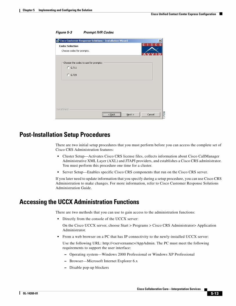
Chapter 5 Implementing and Configuring the SolutionCisco Unified Contact Center Express Configuration
Figure 5-3 Prompt IVR Codec
Post-Installation Setup ProceduresThere are two initial setup procedures that you must perform before you can access the complete set of Cisco CRS Administration features:
• Cluster Setup—Activates Cisco CRS license files, collects information about Cisco CallManager Administrative XML Layer (AXL) and JTAPI providers, and establishes a Cisco CRS administrator. You must perform this procedure one time for a cluster.
• Server Setup—Enables specific Cisco CRS components that run on the Cisco CRS server.
If you later need to update information that you specify during a setup procedure, you can use Cisco CRS Administration to make changes. For more information, refer to Cisco Customer Response Solutions Administration Guide.
Accessing the UCCX Administration FunctionsThere are two methods that you can use to gain access to the administration functions:
• Directly from the console of the UCCX server:
On the Cisco UCCX server, choose Start > Programs > Cisco CRS Administrator> Application Administrator.
• From a web browser on a PC that has IP connectivity to the newly-installed UCCX server:
Use the following URL: http://<servername>/AppAdmin. The PC must meet the following requirements to support the user interface:
– Operating system—Windows 2000 Professional or Windows XP Professional
– Browser—Microsoft Internet Explorer 6.x
– Disable pop-up blockers
5-13Cisco Collaborative Care—Interpretation Services
OL-14269-01

Chapter 5 Implementing and Configuring the SolutionCisco Unified Contact Center Express Configuration
Installing License FileOnce UCCX has been installed, you must next install the license file which is part of the cluster setup post installation steps.
To install the license file:
Step 1 On the Cisco CRS Administrator Setup screen, click Setup.
You see the License Information page.
Step 2 In the License File field, enter the path and name of a Cisco CRS license file or of a ZIP file that contains multiple license files.
Step 3 Click Next. The License Information page appears again.
Step 4 Take one of these actions:
• If you wish to enter multiple license files that you have not put into a single ZIP file, enter the path and name of another license file in the License File field and then click Next. The license information page appears again. Repeat this process until you have entered all license files.
• If you have entered the name of a ZIP file that contains multiple license files or have entered all your license files, leave the License File field blank and click Next.
The CallManager Configuration screen appears. This page displays the IP address of the primary AXL server provider that is configured for Cisco CRS and lets you specify backup AXL server providers. It also lets you specify the IP addresses of JTAPI providers and RmCm providers that are configured for Cisco CallManager. See the next section for information on completing these steps.
Configuring UCCX for CallManagerOnce you have installed the License file, you see the CallManager Configuration screen:
5-14Cisco Collaborative Care—Interpretation Services
OL-14269-01

Chapter 5 Implementing and Configuring the SolutionCisco Unified Contact Center Express Configuration
The AXL Service must be configured and running on the Unified CallManager server, but first, this needs to be configured on UCCX.
In the AXL Service Provider Configuration area:
Step 1 If there are other available AXL service providers that Cisco CRS should use to access Cisco CallManager if the primary AXL service provider fails, move the IP address of each backup AXL service provider that you want from the Available AXL Service Providers list box to the Selected AXL Service Providers list box. Click the left arrow to move the selected IP address from the Available AXL Service Providers list box.
Step 2 If there is more than one item in the Selected AXL Service Providers list box, make sure that the IP address of the primary CallManager running the AXL service appears at the top of the list, followed by the backup CallManagers running the AXL service providers in the order that they should be used if an AXL service failover occurs. Use the up arrow or the down arrow next to the Selected AXL Service Providers list box to specify the order of these servers.
5-15Cisco Collaborative Care—Interpretation Services
OL-14269-01

Chapter 5 Implementing and Configuring the SolutionCisco Unified Contact Center Express Configuration
Step 3 In the User Name and Password fields, enter the Cisco CallManager user name and password, if you want to change the information that appears in these fields.
The JTAPI (Java Telephony API) protocol is used by UCCX to communicate with CallManager. It is through this communication protocol that CallManager notifies UCCX of an inbound call and how UCCX likewise informs CallManager of the agent to which the call should be routed.
In the JTAPI Provider Configuration area:
Step 1 Move the IP address of up to two CTI managers from the Available CTI Managers list to the Selected CTI Managers list box. Click the left arrow to move the selected IP address from the Available CTI Managers list box.
Step 2 If there is more than one item in the Available CTI Managers list box, make sure that the primary CTI manager appears at the top of the list, followed by the backup CTI manager. Use the up-arrow or the down-arrow next to the Selected CTI Managers list box to specify the order of these servers.
Step 3 In the User Prefix field, enter the prefix of the JTAPI provider that you want to create in Cisco CallManager. Cisco CRS automatically appends the node ID to this prefix and creates the JTAPI provider in Cisco CallManager.
Step 4 In the Password and Confirm Password fields, enter and confirm the password for the JTAPI provider.
The Resource Manager-Contact Manager, otherwise known as RmCm Subsystem, is broken down into two components. The RM or Resource Manager manages resources such as agents as to their state, Not-Ready, Ready, Working, Logged out, etc. The Contact Manager subsystem provides management of queues and participates in routing calls to agent resources.
In the RmCm Provider Configuration area:
Step 1 Move the IP address of up to two CTI managers from the Available CTI Managers list to the Selected CTI Managers list Box. Click the left arrow to move the selected IP address from the Available CTI Managers list box.
Step 2 If there is more than one item in the Available CTI Managers list box, make sure that the primary CTI manager appears at the top of the list, followed by the backup CTI manager. Use the up-arrow or the down-arrow next to the Selected CTI Managers list box to specify the order of these servers.
Step 3 In the User ID field, enter ID of the RmCm provider that you want to create in Cisco CallManager.
Step 4 In the Password and Confirm Password fields, enter and confirm the Password for the RmCm provider.
Configuration of UCCXFor deployment model 3, the UCCX infrastructure is managed by the Language Interpretation Service and therefore this section is not applicable for the health care provider.
5-16Cisco Collaborative Care—Interpretation Services
OL-14269-01

Chapter 5 Implementing and Configuring the SolutionCisco Unified Contact Center Express Configuration
Creating Skills
Agents are assigned one or more skills for which they are responsible. The skills assigned to the agents can each have a specific level of competence specified.
To create skills:
Step 1 From the CRS Administration menu bar, choose Subsystems/RmCm. The UCCX Configuration web page opens, displaying the RM JTAPI Provider area.
Step 2 On the UCCX Configuration navigation bar, click the skills hyperlink. The UCCX Configuration skills summary web page opens to display the Skill Name (customer-definable label assigned to an agent), if configured.
Step 3 Click the Add a New Skill hyperlink.
Step 4 Enter the Skill Name as shown below, then click the Add button.
Creating Contact Service Queues (CSQs)
Unified Contact Center Express uses a grouping mechanism for callers requiring similar services. In our case, these CSQs would map to language. These CSQs are what is referenced within the script which is executing on the UCCX platform and interacting with the caller.
To create CSQs:
5-17Cisco Collaborative Care—Interpretation Services
OL-14269-01

Chapter 5 Implementing and Configuring the SolutionCisco Unified Contact Center Express Configuration
Step 1 Enter the CSQ Name as shown in the example, then press Next.
Step 2 Once Next has been selected, you are asked to assign the skills that are used by the agents for this set of callers. Since our example is a 1:1 mapping, the CSQ-Spanish queue contains only one skill, Spanish. The Resource Selection Criteria should be set to Longest Available as shown. This selects the agent that has been available the longest. There are a number of other agent selection methods that can be used.
5-18Cisco Collaborative Care—Interpretation Services
OL-14269-01

Chapter 5 Implementing and Configuring the SolutionCisco Unified Contact Center Express Configuration
Adding Agent Resources
Agent resources are first defined as users in Unified CallManager. On the “End User” configuration page, there is an option that is used to specify the UCCX Extension. This drop down displays the extension assigned to the user, and if this option is not specified, the userid is not exported to Unified Contact Center Express. This drop down is shown below.
Note IP Contact Center (IPCC) has been recently renamed to UCCX, so references toIPCC in the Unified CallManager are referring to the IPCC suite of applications which is inclusive of UCCX.
Once the agent has been identified in Unified CallManager as an UCCX agent resource, the agent should now be present in the UCCX system which is found under Subsystem/RmCm/Resources.
The name of the resource shown in Unified Contact Center Express (UCCX) is the last name of the end user as defined in Unified CallManager and not the userid of the end user.
5-19Cisco Collaborative Care—Interpretation Services
OL-14269-01

Chapter 5 Implementing and Configuring the SolutionCisco Unified Contact Center Express Configuration
Assigning Agents to Skills
To assign skills to the agent resources, select the Resource Name as shown on the RmCm/Resources menu (shown above). The following screen is displayed.
Select one or more skills and press the left arrow to move that skill into the Assigned Skills column. Each skill selected can have a unique competence level, depending on the skill level of the translator, or for other business reasons. One example is to reduce the calls that may interrupt a translator that has other primary responsibilities, but within the health care organization is used as overflow in the event that the full time interpreters are not available.
Uploading Scripts to UCCX
Scripts are developed using the CRS Editor tool which is included with Unified Contact Center Express. Once the script has been created, it must be uploaded to the UCCX system. These scripts are stored in the Repository Data Store (RDS) database, along with other information such as prompts, grammars, and various document files on the UCCX System.
From the UCCX Administration menu, choose Applications/Script Management.
The Script Management page opens as shown below.
5-20Cisco Collaborative Care—Interpretation Services
OL-14269-01

Chapter 5 Implementing and Configuring the SolutionCisco Unified Contact Center Express Configuration
Clicking on the Script Files directory, followed by Upload New Scripts, opens an upload dialogue box that allows you to upload the script file(s) from your local machine.
Once the upload has been performed, you are presented with a dialogue box confirming the upload. If you are replacing a script that is already in use, the dialogue box lets you refresh the script. If you do not refresh the script, the old copy is used by all applications and subsystems within the UCCX system.
There are two script refresh options:
• Individual script refresh
• Bulk script refresh
Note If a large number of VRU (Voice Response Unit) scripts are configured for your system, the Upload a New Script and Refresh Scripts operations can take a long time to complete. These tasks can also result in high CPU utilization and hence should be performed with caution, especially during peak times of system usage.
5-21Cisco Collaborative Care—Interpretation Services
OL-14269-01

Chapter 5 Implementing and Configuring the SolutionCisco Unified Contact Center Express Configuration
Linking Applications to Scripts
Once the scripts are uploaded, applications must be created that define a JTAPI trigger (or pilot number) and map it to a script. To create an application, select Applications/Application Management/Add a New Application as shown below.
When adding a new application that uses a script, select Cisco Script Application and press Next.
Specify the maximum number of sessions that this application is allowed to support. This selection directly correlates to the number of CTI ports that have been defined for the UCCX system to use. In this example, up to 10 callers can be interacting with the script at any one time. Next, select the Script name
5-22Cisco Collaborative Care—Interpretation Services
OL-14269-01

Chapter 5 Implementing and Configuring the SolutionCisco Unified Contact Center Express Configuration
from the script drop down menu. Any variables that have been defined in the script as a parameter are listed below. Typical variables that are defined with the parameters are prompts, retry counts, and delay seconds. This allows you to override the variable without having to edit the script. In most cases, you won’t need to change this. Next select the Add button shown above
Once the application has been added, you are presented with the opportunity to define JTAPI triggers. Select Add new trigger from the menu as shown below.
The added trigger can be one of two types:
• Traditional IVR DTMF-based trigger
• An http-based trigger that is executed from within a web browser session that the clinician would initiate
In this example, we choose a standard JTAPI trigger that is used when the clinician dials the number specified for the trigger.
On the next screen, you are required to enter values for a number of fields. Specifying the directory number that the end user dials creates the JTAPI trigger. The CTI Route Point is automatically configured in Unified CallManager. Think of these as route patterns that CallManager uses to determine that calls to this number are calls to the application being defined in UCCX. The Route Points in CallManager are by default named RP_ + the directory number specified. In this case it would be RP_4560. Once this has been configured, select Add to complete the JTAPI trigger configuration task.
5-23Cisco Collaborative Care—Interpretation Services
OL-14269-01

Chapter 5 Implementing and Configuring the SolutionCisco Unified Contact Center Express Configuration
You may confirm that the route point has been automatically added to the Unified CallManager by selecting Device/CTI Route Point. It is strongly recommended not to manually change the CTI route point configuration from within CallManager as it may be overridden or refreshed from UCCX.
5-24Cisco Collaborative Care—Interpretation Services
OL-14269-01

Chapter 5 Implementing and Configuring the SolutionCisco 7985 Phone Configuration
Multiple Route Points
It is possible to configure a number of different route points that all map to the same application. This may be useful in this solution deployment in that 4560 could be the main pilot number that provides the user with an audible list of languages to choose from. It may however be advantageous to offer the caller a number of different entry points in the form of separate phone numbers (JTAPI Triggers) for each language (in our example, 4561 for Spanish,4562 for Sign Language, etc.).
When the script executes, a simple check of the dialed phone number or JTAPI trigger used to invoke the application can be performed. This prevents the caller from having to navigate the IVR-based menu system and streamlines access to the language of choice. Furthermore, speed dials can be configured on the endpoint devices that map the text Spanish to extension 4561 and so on.
Cisco 7985 Phone Configuration
Audio SettingsThe audio settings of the Cisco 7985 are configured on CallManager in the Region settings. It is recommended to create a Video Region and associate all Video endpoints, Route Points, and SIP trunks to this region. When the endpoint is defined to Callmanager either through auto registration or manually, it is assigned to either the default region or manually assigned to a administrator-defined region. In this way it is possible to have a subset of devices utilize the G.722 codec, which provides for greater audio clarity.
The Cisco 7985 has an integrated microphone and speakers. The Cisco 7985 supports the G.722 audio codec and adopts this setting as part of the configuration process when registering with Unified CallManager.
5-25Cisco Collaborative Care—Interpretation Services
OL-14269-01
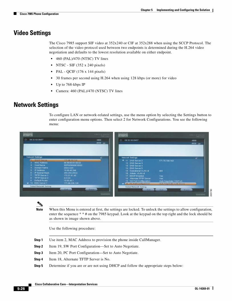
Chapter 5 Implementing and Configuring the SolutionCisco 7985 Phone Configuration
Video SettingsThe Cisco 7985 support SIF video at 352x240 or CIF at 352x288 when using the SCCP Protocol. The selection of the video protocol used between two endpoints is determined during the H.264 video negotiation and defaults to the lowest resolution available on either endpoint.
• 460 (PAL)/470 (NTSC) TV lines
• NTSC - SIF (352 x 240 pixels)
• PAL - QCIF (176 x 144 pixels)
• 30 frames per second using H.264 when using 128 kbps (or more) for video
• Up to 768-kbps IP
• Camera: 460 (PAL)/470 (NTSC) TV lines
Network SettingsTo configure LAN or network-related settings, use the menu option by selecting the Settings button to enter configuration menu options. Then select 2 for Network Configurations. You see the following menu:
Note When this Menu is entered at first, the settings are locked. To unlock the settings to allow configuration, enter the sequence * * # on the 7985 keypad. Look at the keypad on the top right and the lock should be as shown in image shown above.
Use the following procedure:
Step 1 Use item 2, MAC Address to provision the phone inside CallManager.
Step 2 Item 19, SW Port Configuration—Set to Auto Negotiate.
Step 3 Item 20, PC Port Configuration—Set to Auto Negotiate.
Step 4 Item 18, Alternate TFTP Server is No.
Step 5 Determine if you are or are not using DHCP and follow the appropriate steps below:
5-26Cisco Collaborative Care—Interpretation Services
OL-14269-01

Chapter 5 Implementing and Configuring the SolutionCisco 7985 Phone Configuration
If using DHCP:
a. Item 17 DHCP Enabled, set this to Yes.
b. Once connected to the access switch, DHCP finds the DHCP Server and the following fields are populated by the DHCP Server.
– DHCP Server
– IP Address
– IP Subnet Mask
– TFTP Server 1
– TFTP Server 2 if alternate is defined
– Default Router
– DNS Server 1
– DNS Server 2, 3, 4, 5 if applicable
– Operational VLAN ID
If not using DHCP:
a. Item 17 DHCP Enabled, set this to NO.
b. Manually enter the following values as assigned by the Network IT:
– DHCP Server
– IP Address
– IP Subnet Mask
– TFTP Server 1
– TFTP Server 2 if alternate is defined
– Default Router
– DNS Server 1
– DNS Server 2, 3, 4, 5 if applicable
– Operational VLAN ID
Verifying Proper Operation
To verify that the Cisco 7985 has successfully registered with CallManager, a phone number appears at the top right corner on the main screen. To get more detail on the status, select the Settings key and choose option 5 Status. To verify the Network settings, select 3 - Network Statistics.
Determining the System Information
To determine the firmware, revision, mac address, and other system details, select Settings and choose option 4. You should see the following:
5-27Cisco Collaborative Care—Interpretation Services
OL-14269-01

Chapter 5 Implementing and Configuring the SolutionPolycom PVX Phone Configuration
Note Some models show a Boot Load ID of S01655 1.4, 2005-06-13 which works as well.
XML Applications for 7985 for IPPASee Agent Software with UCCX.
Polycom PVX Phone ConfigurationThis section provides configuration details on configuring the Polycom PVX to work in the Collaborative Care solution.
• Registration to a gatekeeper
• Setup for audio and video options
• Network settings
For installation, general information, PC platform requirements, camera/microphone recommendations, and detailed product guidelines on Polycom PVX, refer to the product page for Polycom PVX:
http://www.polycom.com/products_services/1,,pw-7953,00.html
After completing installation and registration of the Polycom PVX, follow this procedure:
5-28Cisco Collaborative Care—Interpretation Services
OL-14269-01

Chapter 5 Implementing and Configuring the SolutionPolycom PVX Phone Configuration
Note Only the options essential to configure Polycom PVX to work as a clinician endpoint are shown.
Step 1 Chose General > General.
• In the User Name, enter a field that is used as the unique H.323-ID for this endpoint. The E-mail address should follow the user name with the E-mail domain address.
• The recommended setting for Video and Audio Device Preference is Use ViaVideo hardware, if present.
Step 2 Choose General > Call Settings—An option to set the maximum duration of a call in duration of minutes. If no maximum is required, then set the value to 0.
Step 3 Choose General > Performance—An option for the performance to allocate to the PVX application. If no other application is running on the tablet PC, then set this for Polycom PVX. If other applications are used on the PC, then set this value to Balanced.
Step 4 Choose Video > Video Protocol.
5-29Cisco Collaborative Care—Interpretation Services
OL-14269-01

Chapter 5 Implementing and Configuring the SolutionPolycom PVX Phone Configuration
In this setting, ensure the Enhanced video (H.264) status option is checked to use H.264 video.
Step 5 Choose Video > Advanced.
5-30Cisco Collaborative Care—Interpretation Services
OL-14269-01

Chapter 5 Implementing and Configuring the SolutionPolycom PVX Phone Configuration
In this menu select the following to achieve the best video performance:
• Enable VGA people encoding
• Enable VGA 30 frames per second
• Select High for the camera driver’s CPU load
Step 6 Choose Audio.
5-31Cisco Collaborative Care—Interpretation Services
OL-14269-01

Chapter 5 Implementing and Configuring the SolutionPolycom PVX Phone Configuration
This menu selection depends on the audio output and input device. If the device has a hardware-based echo cancellation, then choose External for Echo Cancellation. If the hardware device does not have that capability, then choose Internal.
Always select Automatic Gain Control to help provide consistent volume control.
Step 7 Chose Network > Connections.
Selection Directly connected to a LAN or behind a fully aware H.323 firewall since the Cisco ASA FW is fully H.323 aware and the CallManager also performs protocol translation to SIP or SCCP depending on the call destination.
Step 8 Choose Network > Ports.
Ensure that H.323 TCP Port is set for 1720.
Unless there are conflicts with the Media Ports, there is no requirement to change the Media Ports.
Step 9 Choose Network > QoS.
Select Increase priority of video conferencing data on your network.
Step 10 Choose Network > Bandwidth.
5-32Cisco Collaborative Care—Interpretation Services
OL-14269-01

Chapter 5 Implementing and Configuring the SolutionPolycom PVX Phone Configuration
Under this menu select 768 kbps for both he Default Call Rate and the Maximum Call Rate. All endpoints used are capable of 768 kbps.
Step 11 Choose H.323.
5-33Cisco Collaborative Care—Interpretation Services
OL-14269-01

Chapter 5 Implementing and Configuring the SolutionPolycom PVX Phone Configuration
• Under Gatekeeper, select Specify and enter the IP address of the Gatekeeper.
• Under H.323 Extension (E.164), enter the directory number as defined also in the Cisco CallManager for the H.323 line number.
Note The E.164 address in the Cisco CallManager must be consistent with E.164 entered in this menu.
Tip To detect if the H.323 PVX endpoint is registered, enter this menu to see the status. In this case, it shows the Gatekeeper registration was successful. Going to the Gatekeeper, the endpoint should also show the device registered.
Tip To get call statistics, choose Stats > Call Statistics to get call history and Stats > Media Statistics to see the type of bearer channels used for voice and video.
5-34Cisco Collaborative Care—Interpretation Services
OL-14269-01
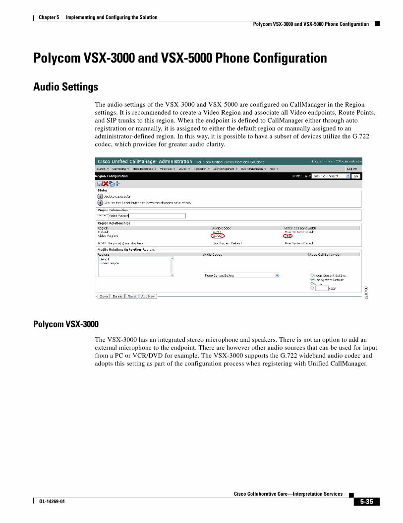
Chapter 5 Implementing and Configuring the SolutionPolycom VSX-3000 and VSX-5000 Phone Configuration
Polycom VSX-3000 and VSX-5000 Phone Configuration
Audio SettingsThe audio settings of the VSX-3000 and VSX-5000 are configured on CallManager in the Region settings. It is recommended to create a Video Region and associate all Video endpoints, Route Points, and SIP trunks to this region. When the endpoint is defined to CallManager either through auto registration or manually, it is assigned to either the default region or manually assigned to an administrator-defined region. In this way, it is possible to have a subset of devices utilize the G.722 codec, which provides for greater audio clarity.
Polycom VSX-3000
The VSX-3000 has an integrated stereo microphone and speakers. There is not an option to add an external microphone to the endpoint. There are however other audio sources that can be used for input from a PC or VCR/DVD for example. The VSX-3000 supports the G.722 wideband audio codec and adopts this setting as part of the configuration process when registering with Unified CallManager.
5-35Cisco Collaborative Care—Interpretation Services
OL-14269-01

Chapter 5 Implementing and Configuring the SolutionPolycom VSX-3000 and VSX-5000 Phone Configuration
Polycom VSX-5000
The VSX-5000 requires the use of an external microphone and speaker. Typically the VSX-5000 is placed on the top of a video monitor that has either S-Video or VGA/XGA video output. Stereo outputs are supplied and can be connected to an external speaker system either on the video monitor or external to speakers located in the room.
Video SettingsBoth the VSX-3000 and VSX-5000 support SIF video at 352x240 or CIF at 352x288 when using the SCCP protocol. The selection of the video protocol used between two endpoints is determined during the H.264 video negotiation and defaults to the lowest resolution available on either endpoint.
• NTSC 30fps at 56Kbps-2Mbps
• PAL 24fps at 56Kbps-2Mbps
5-36Cisco Collaborative Care—Interpretation Services
OL-14269-01

Chapter 5 Implementing and Configuring the SolutionPolycom VSX-3000 and VSX-5000 Phone Configuration
• ITU based full screen Pro-Motion TM
• H.263 interlaced video (60/50 fields full screen video for NTSC/PAL)
• SIF (352 x 240), CIF (352 x 288)
• QSIF (176 x 120), QCIF (176 x 144)
Network SettingsThe network settings and general configuration menus are the same for both the VSX-3000 and VSX-5000 devices. To configure LAN or network-related settings, use the remote control to select System/Admin Settings/LAN Properties. Any of the following items can be changed in this menu and are shown below.
• Hostname
• IP Address
• Domain Name
• DNS Server
• Default Gateway
• Subnet Mask
• WINS Server
• WINS Resolution
• LAN Speed & Duplex
Configuring the VSX System to Use SCCP Protocol
Using the remote control, select System/Admin Settings/Network/SCCP Settings and configure the following:
• Auto Discover TFTP Address—This option allows DHCP to configure the IP address of the TFTP server, which is typically Cisco CallManager. This information in the form of an IP address is delivered to all DHCP hosts via DHCP Option 150.
• TFTP Server Address—If you do not enable the auto discovery option for CallManager as described above, you must manually configure the IP address of the CallManager here. Up to three addresses can be specified and are used in priority order until the VSX system is able to register with CallManager.
5-37Cisco Collaborative Care—Interpretation Services
OL-14269-01

Chapter 5 Implementing and Configuring the SolutionPolycom VSX-3000 and VSX-5000 Phone Configuration
When the VSX system has registered with CallManager, the directory number that was assigned to the device is displayed directly below the self video image. Additionally the CallManager Address is displayed when you navigate to System/Admin Settings/Network/SCCP.
Verifying Proper Operation
To verify that the VSX system (3000 or 5000) has successfully registered with CallManager, select Diagnostics/System Status found under the System menu option. If registered, you see a green up-arrow indicating that the VSX system has registered to CallManager.
Determining the System Information
To determine the firmware, revision, Mac address, and other system details, select System/System Information. You see the following fields:
• System Name
• Model Number
• Serial Number
• IP Video Number
• System Software
• Mac Address
• Boot UI Version
• IP Address
• CallManager Name
• Call Manager Version
• DSCP Information
5-38Cisco Collaborative Care—Interpretation Services
OL-14269-01

Chapter 5 Implementing and Configuring the SolutionTandberg T1000 MXP Phone Configuration
Firmware Upgrades
You can download a new version of firmware directly from Polycom’s website. The upgrade process is straightforward through the use of the Softupdate application.
To update your software via the Internet:
Step 1 Using a web browser, go to http://www.polycom.com/videosoftware and log in to the Polycom Resource Center. You may need to set up a PRC account if you do not already have one.
Step 2 Navigate to your product page for your specific product. Refer to the release notes for information about the latest software version.
Step 3 Review the Upgrading Polycom Video Software documentation available for your VSX system for more detailed information on how to obtain a software key code and helpful hints in using the SoftUpdate program.
Step 4 Download the VSX Series SoftUpdate file in.zip format.
Step 5 Once you have obtained your Software Key Code from Polycom, you can execute the SoftUpdate program on your PC provided that it has IP connectivity to the VSX system.
Step 6 Once the application starts, it asks you for the IP address of the VSX system to upgrade, as well as the Software Key Code. In addition, you are asked for your remote access password as configured on the VSX system. This password can be changed via System/Admin Settings/General Settings/Security. Once supplied, the upgrade process should begin.
Note Do not interrupt the upgrade process; if you do, the system may be unusable.
Tandberg T1000 MXP Phone Configuration
Audio SettingsThe audio settings of the T1000 MXP when using SCCP is configured in the CallManager Region settings. It is recommended to create a Video Region and associate all Video endpoints, Route Points, and SIP trunks to this region. When the endpoint is defined to CallManager either through auto registration or manually, it is assigned to either the default region or manually assigned to an administrator-defined region. In this way, it is possible to have a subset of devices utilize the G.722 codec, which provides for greater audio clarity.
5-39Cisco Collaborative Care—Interpretation Services
OL-14269-01

Chapter 5 Implementing and Configuring the SolutionTandberg T1000 MXP Phone Configuration
Video SettingsThe T1000 MXP supports H.264 video at up to 30fps at the following video resolutions:
• SIF (352 x 240)
• CIF (352 x 288)
The selection of the video protocol used between two endpoints is determined during the H.264 video negotiation and defaults to the lowest resolution available on either endpoint.
Network SettingsThe network settings and general configuration menus for the Tandberg T1000 MXP are navigated using the remote control included with each T1000. To configure the LAN or network-related settings, select Settings/Network Settings. Any of the following items can be changed in this menu and are shown below.
• DNS Settings
• IP Settings:
– IP Assignment DHCP or Static
– If Static, IP Address, Subnet Mask, Default Gateway
– Ethernet Speed 10/Half, 10/Full, 100/Half, 100/Full or Automatic
– IP Access password used for remote access to the T1000 MXP
5-40Cisco Collaborative Care—Interpretation Services
OL-14269-01

Chapter 5 Implementing and Configuring the SolutionTandberg T1000 MXP Phone Configuration
• TFTP Settings—This setting is used to specify the IP Address of the CallManager. It can be automatically obtained via DHCP or the DHCP option 150 can be overridden by the manual configuration as shown.
– Alternate TFTP Server (Yes/No)—This option allows DHCP to configure the IP address of the TFTP server, which is typically Cisco CallManager. This information in the form of an IP address is delivered to all DHCP hosts via DHCP Option 150.
– TFTP Server Address—If you enable the Alternate TFTP Server field, you can specify up to two TFTP Server addresses. These are used in priority order until the T1000 MXP is able to register with CallManager.
Verifying Proper Operation
To verify that the T1000 MXP has successfully registered with CallManager, select System Status found under the Settings/View Status menu option. If registered to CallManager, you see the word Active next to the CallManager 1 field shown in the lower portion of the second screen below.
You see the following information:
• Active IP Address
• Active IP Subnet Mask
• Active Gateway
• Boot Load ID
• Software Version
5-41Cisco Collaborative Care—Interpretation Services
OL-14269-01

Chapter 5 Implementing and Configuring the SolutionTandberg T1000 MXP Phone Configuration
• Serial Number
• MAC Address
• Ethernet Speed
• VLAN ID
• Various WLAN settings (not used in this solution)
• CallManager 1
Firmware Upgrades
Unlike other Cisco endpoints, the T1000 does not download its firmware from the CallManager. Before starting the upgrade, make sure that you have obtained a Release Key from Tandberg. The release key is unique to each T1000 MXP and can only be obtained directly from Tandberg technical support or a Tandberg reseller.
The system can be upgraded through FTP or a Web browser (IE 6.0+) interface.
Web Interface Upgrade Method
To upgrade using the web interface, point the browser to the IP address of the T1000 MXP system. To obtain the IP address of the system, use the System Status menu as shown above. Once you have entered this address, you should be prompted with the system web menu. Select the System Configuration Tab and then select upgrade.
5-42Cisco Collaborative Care—Interpretation Services
OL-14269-01

Chapter 5 Implementing and Configuring the SolutionTandberg T1000 MXP Phone Configuration
Enter the Release key provided by Tandberg or your Tandberg reseller. Once entered, press the Install Software button. The next menu should be displayed, provided that the serial number dependent release key that you entered is valid for the T1000 MXP. At this point, simply enter the image filename and path or use the browse button to navigate to the location of the file.
Pressing the Install button begins the install process.
FTP Upgrade Method
Step 1 Copy the new firmware to a folder on your local hard disk.
Step 2 From a DOS window, navigate to the folder where the new firmware is stored.
Step 3 Enter ftp <ip address of the T1000 MXP>.
Step 4 Type in the Release Key as the UserID. You should have obtained this from Tandberg or your Tandberg reseller.
Step 5 Type in your password; the default is TANDBERG.
Step 6 Type bin and press enter.
5-43Cisco Collaborative Care—Interpretation Services
OL-14269-01

Chapter 5 Implementing and Configuring the SolutionAgent Software with UCCX
Step 7 Type put <firmware filename> and press Enter.
Step 8 The upload should start.
Step 9 Once completed, close your FTP session and restart the T1000 to boot with the new firmware.
Agent Software with UCCX
Configuring Cisco Agent Desktop (CAD)Configuring an agent in Unified CallManager is as simple as adding an end user and then assigning an endpoint device to the account. The directory numbers assigned to the lines on the phone are automatically displayed in the primary extension field. It is critical to also assign an UCCX Extension to the end user account to trigger the export of that user to UCCX. Note that after the renaming of IPCC to UCCX, Unified CallManager still refers to UCCX as IPCC.
The Cisco Agent Desktop (CAD) is a Windows-based client that allows the agent to interact with the UCCX system. The agent is able to login to UCCX through CAD and change their state as necessary in order to signal to UCCX whether it should direct calls to this particular agent.
Note If the agent switches between using CAD and IP Phone Agent (IPPA), the length of the agent userid should be kept to a minimum. For more detailed information, see Installing IP Phone Agent (IPPA).
Endpoints that use CAD must be associated not only to the primary agent/end user, but also to a special application user account that was created in Unified CallManager during the initial install of UCCX. This user account is listed under User Management/Application User in CallManager and has the form xx-RmCm, where xx was a two character prefix specified at the time of the UCCX installation.
This xx-RmCm application user account needs to be associated with each endpoint that uses CAD. This enabled UCCX to query the status of the endpoint using the JTAPI protocol. Without this association, CAD does not fully initialize and end its agent logon process when it attempts to query CallManager for the device status (register, on-hook, off-hook, etc.).
To associate the endpoint devices, simply move the MAC address of the endpoints from the Available Device section into the associated section as shown below. All devices that use CAD or IPPA must be in the lower section as shown, and not in the upper section.
5-44Cisco Collaborative Care—Interpretation Services
OL-14269-01

Chapter 5 Implementing and Configuring the SolutionAgent Software with UCCX
Installing CAD on the Windows Workstation
To install Cisco Agent Desktop:
Step 1 Open your web browser and access the Cisco Unified Contact Center Express User web page at http://servername/appuser. Replace server name with the host name or IP address of the UCCX server name or IP address.
Step 2 The Unified Contact Center Express system user authentication window appears. At the prompt, enter your user name and password and then click Log On. The Welcome window appears.
5-45Cisco Collaborative Care—Interpretation Services
OL-14269-01
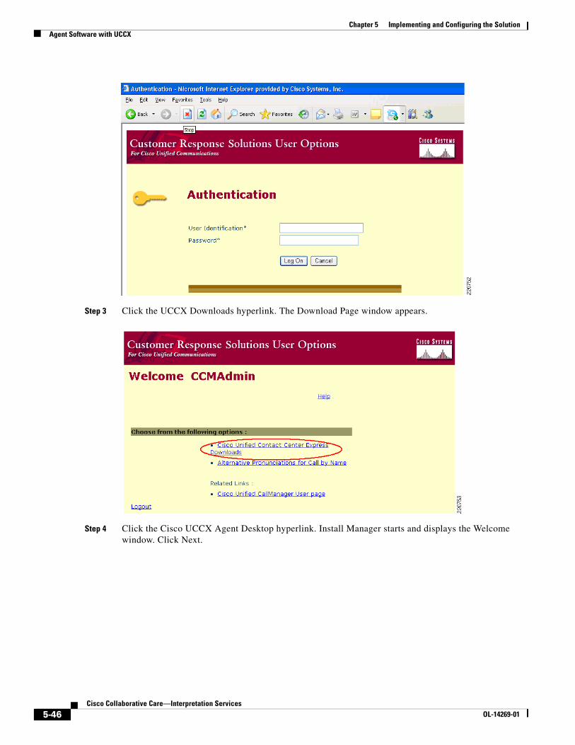
Chapter 5 Implementing and Configuring the SolutionAgent Software with UCCX
Step 3 Click the UCCX Downloads hyperlink. The Download Page window appears.
Step 4 Click the Cisco UCCX Agent Desktop hyperlink. Install Manager starts and displays the Welcome window. Click Next.
5-46Cisco Collaborative Care—Interpretation Services
OL-14269-01

Chapter 5 Implementing and Configuring the SolutionAgent Software with UCCX
Step 5 The Installation Server: Location dialog box appears. Enter the host name or IP address and port number of the UCCX Web Server and click Next. This may be already populated for you; if so, leave the fields as shown. The host name or IP address is the same one you used to access the UCCX web interface.
Step 6 Select the version of CAD you wish to install and click Next. The License Agreement dialog box appears. Click Yes to accept the End User License Agreement.
5-47Cisco Collaborative Care—Interpretation Services
OL-14269-01

Chapter 5 Implementing and Configuring the SolutionAgent Software with UCCX
Step 7 The Choose Destination Location dialog box appears. Accept the default destination folder or click Browse to navigate to another destination folder, then click Next.
Step 8 The Start Copying Files dialog box appears. Click Next to start the installation. Install Manager installs the application you chose.
5-48Cisco Collaborative Care—Interpretation Services
OL-14269-01
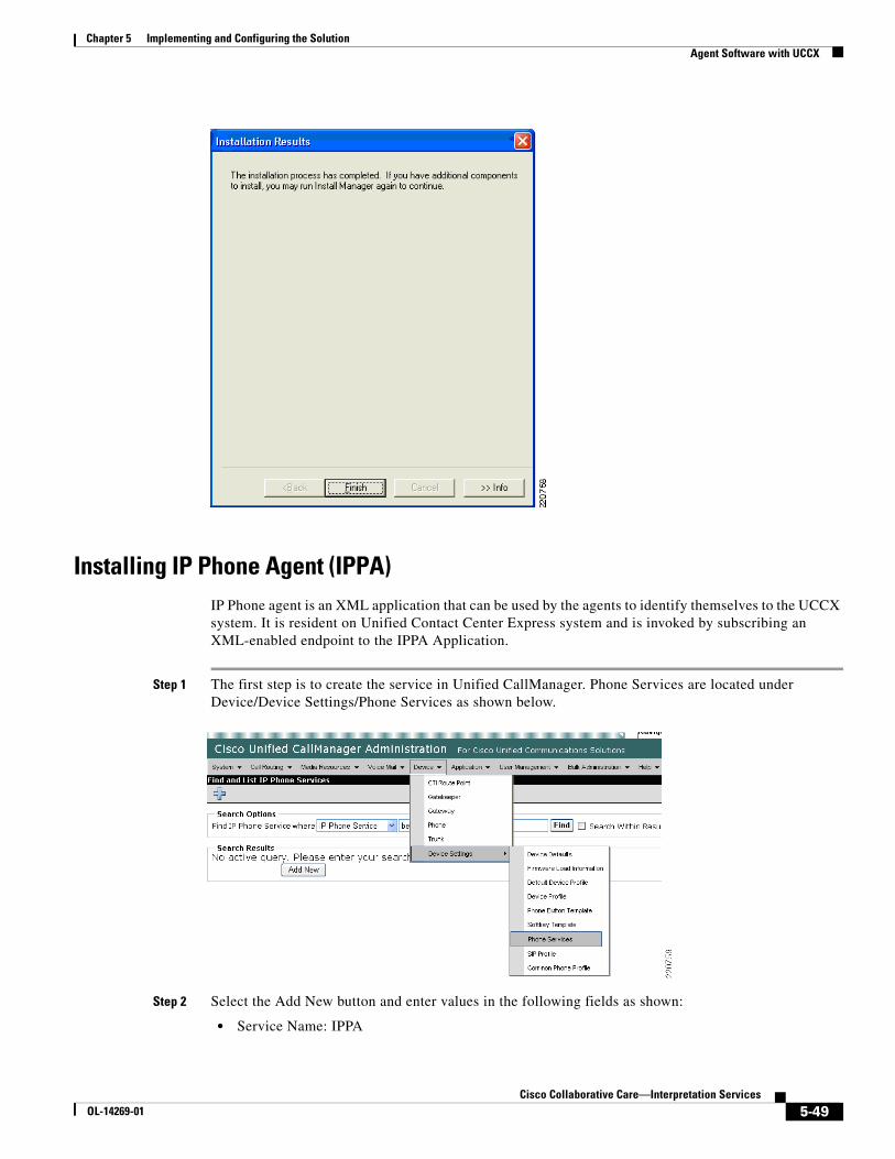
Chapter 5 Implementing and Configuring the SolutionAgent Software with UCCX
Installing IP Phone Agent (IPPA)IP Phone agent is an XML application that can be used by the agents to identify themselves to the UCCX system. It is resident on Unified Contact Center Express system and is invoked by subscribing an XML-enabled endpoint to the IPPA Application.
Step 1 The first step is to create the service in Unified CallManager. Phone Services are located under Device/Device Settings/Phone Services as shown below.
Step 2 Select the Add New button and enter values in the following fields as shown:
• Service Name: IPPA
5-49Cisco Collaborative Care—Interpretation Services
OL-14269-01

Chapter 5 Implementing and Configuring the SolutionAgent Software with UCCX
• ASCII Service Name: IPPA
• Service Description: IPPA
• Service URL: http://<UCCX server name or IP>:6293/ipphone/jsp/sciphonexml/IPAgentInitial.jsp
Step 3 Then press the Save button at the bottom. An update successful message should be displayed.
Subscribing XML Phones to the IPPA XML Service
To subscribe a phone to the newly created IPPA XML Service:
Step 1 Select the device as found under Device/Phone located in CallManager. Once you have located the phone to which you want to subscribe the IPPA service, select the Subscribe/Unsubscribe option located on the right as shown below.
Step 2 From the drop down menu, select the IPPA XML Service which you created on CallManager previously, then select Next.
5-50Cisco Collaborative Care—Interpretation Services
OL-14269-01

Chapter 5 Implementing and Configuring the SolutionAgent Software with UCCX
Step 3 You may override the previously configured fields if necessary. This may be necessary to more accurately describe the IPPA function or to distinguish between test and production versions of IPPA that may reside on different Unified Contact Center Express servers.
Step 4 Once you have made the changes (if desired) to the service names, select Subscribe to complete the subscription process.
Starting the IPPA XML Service on Phone
Step 1 By pressing the Services button on the phone, a list of subscribed services should be displayed. One of these services should be IPPA as defined to Unified CallManager in the preceding section.
Step 2 Upon IPPA startup, the user is requested to login using their End User account as defined in CallManager. This userid field may be somewhat cumbersome to enter using the telephone keypad. It is recommended to keep the userid somewhat short and in lower case if at all possible. Once the user enters the ID, Password, and Extension they are presented with the IPPA main screen.
5-51Cisco Collaborative Care—Interpretation Services
OL-14269-01
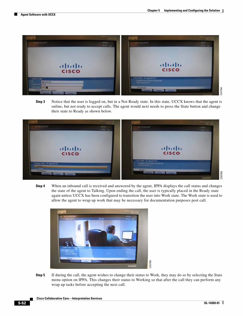
Chapter 5 Implementing and Configuring the SolutionAgent Software with UCCX
Step 3 Notice that the user is logged on, but in a Not Ready state. In this state, UCCX knows that the agent is online, but not ready to accept calls. The agent would next needs to press the State button and change their state to Ready as shown below.
Step 4 When an inbound call is received and answered by the agent, IPPA displays the call status and changes the state of the agent to Talking. Upon ending the call, the user is typically placed in the Ready state again unless UCCX has been configured to transition the user into Work state. The Work state is used to allow the agent to wrap up work that may be necessary for documentation purposes post call.
Step 5 If during the call, the agent wishes to change their status to Work, they may do so by selecting the Stats menu option on IPPA. This changes their status to Working so that after the call they can perform any wrap up tasks before accepting the next call.
5-52Cisco Collaborative Care—Interpretation Services
OL-14269-01

Chapter 5 Implementing and Configuring the SolutionAgent Software with UCCX
IPPA Caveats for the Cisco 7985The 7985 requires that the DNS which has been configured on the phone either manually or via DHCP must be capable of resolving the fully qualified hostname of the Unified CallManager. In other words, if the domain name passed to the 7985 during DHCP configuration is hospital.org and the Unified CallManager hostname is CM1, the DNS server must resolve CM1.hospital.org to the IP address of the CallManager from the viewpoint of the 7985.
If NAT/PAT is being used between the CallManager and the 7985, the DNS server must return the NATed IP address of the CallManager and not its real address. If there are agents inside a firewall performing NAT on the IP address of the CallManager, that DNS server must respond to the DNS request using the actual IP address of the CallManager.
If this is not done, the Services URL button does not function. You can determine if this is the case by selecting the Settings button on the 7985 and selecting HTML Settings. If the URL fields are empty for Directories, Services, etc., then the 7985 was unable to resolve the fully qualified hostname of the CallManager passed to it during its initial boot up sequence. During this sequence, the 7985 requests its configuration file named SEP+MACAddress.cnf.xml via TFTP. This file contains a field called Process NodeName which is the hostname of the CallManager. This field does not change when you change the CallManager Server name via System/Server from a hostname to an IP address.
5-53Cisco Collaborative Care—Interpretation Services
OL-14269-01
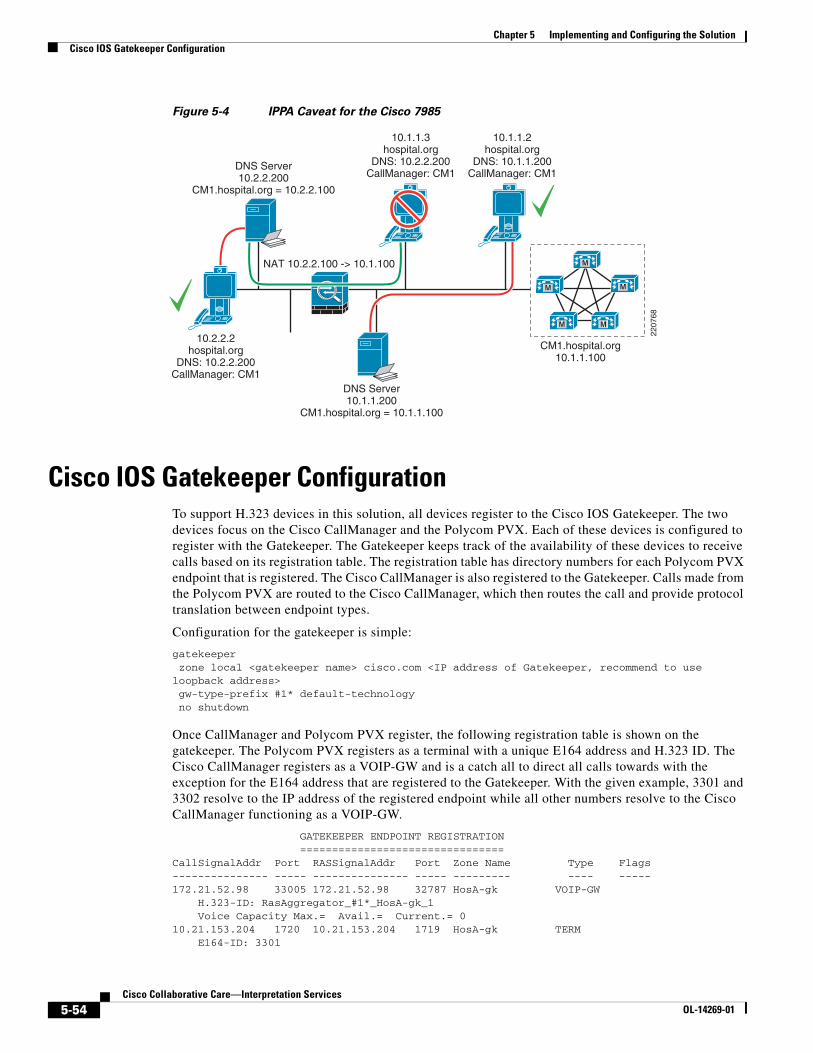
Chapter 5 Implementing and Configuring the SolutionCisco IOS Gatekeeper Configuration
Figure 5-4 IPPA Caveat for the Cisco 7985
Cisco IOS Gatekeeper ConfigurationTo support H.323 devices in this solution, all devices register to the Cisco IOS Gatekeeper. The two devices focus on the Cisco CallManager and the Polycom PVX. Each of these devices is configured to register with the Gatekeeper. The Gatekeeper keeps track of the availability of these devices to receive calls based on its registration table. The registration table has directory numbers for each Polycom PVX endpoint that is registered. The Cisco CallManager is also registered to the Gatekeeper. Calls made from the Polycom PVX are routed to the Cisco CallManager, which then routes the call and provide protocol translation between endpoint types.
Configuration for the gatekeeper is simple:
gatekeeper zone local <gatekeeper name> cisco.com <IP address of Gatekeeper, recommend to use loopback address> gw-type-prefix #1* default-technology no shutdown
Once CallManager and Polycom PVX register, the following registration table is shown on the gatekeeper. The Polycom PVX registers as a terminal with a unique E164 address and H.323 ID. The Cisco CallManager registers as a VOIP-GW and is a catch all to direct all calls towards with the exception for the E164 address that are registered to the Gatekeeper. With the given example, 3301 and 3302 resolve to the IP address of the registered endpoint while all other numbers resolve to the Cisco CallManager functioning as a VOIP-GW.
GATEKEEPER ENDPOINT REGISTRATION ================================CallSignalAddr Port RASSignalAddr Port Zone Name Type Flags--------------- ----- --------------- ----- --------- ---- -----172.21.52.98 33005 172.21.52.98 32787 HosA-gk VOIP-GW H.323-ID: RasAggregator_#1*_HosA-gk_1 Voice Capacity Max.= Avail.= Current.= 010.21.153.204 1720 10.21.153.204 1719 HosA-gk TERM E164-ID: 3301
NAT 10.2.2.100 -> 10.1.100
10.2.2.2hospital.org
DNS: 10.2.2.200CallManager: CM1
DNS Server10.1.1.200
CM1.hospital.org = 10.1.1.100
CM1.hospital.org10.1.1.100
DNS Server10.2.2.200
CM1.hospital.org = 10.2.2.100
10.1.1.3hospital.org
DNS: 10.2.2.200CallManager: CM1
10.1.1.2hospital.org
DNS: 10.1.1.200CallManager: CM1
M
M
M M
M
2207
68
5-54Cisco Collaborative Care—Interpretation Services
OL-14269-01
Chapter 5 Implementing and Configuring the SolutionQoS Configuration
H.323-ID: PhysicianA10.21.153.205 1720 10.21.153.205 1719 HosA-gk TERM E164-ID: 3302 H.323-ID: PhysicianBTotal number of active registrations = 3
QoS Configuration
AutoQoSAutoQoS is a powerful tool to rapidly apply and deploy the QoS model to support the traffic class required for this solution. AutoQoS Enterprise introduced the support for video traffic. For Cisco IOS routers, AutoQos Enterprise detects and provisions for up to ten classes of traffic:
• Voice
• Interactive-Video
• Streaming-Video
• Call-Signaling
• Transactional Data
• Bulk Data
• Routing
• Network Management
• Best Effort
• Scavenger
The AutoQoS Enterprise feature consists of two configuration phases, completed in the following order:
• Auto Discovery (data collection)—Uses NBAR-based protocol discovery to detect the applications on the network and performs statistical analysis on the network traffic.
• AutoQoS template generation and installation—Generates templates from the data collected during the Auto Discovery phase and installs the templates on the interface. These templates are then used as the basis for creating the class maps and policy maps for your network. After the class maps and policy maps are created, they are then installed on the interface.
For devices that do not support the AutoQoS feature, the implementation section provides some configuration steps to classify traffic accordingly using a DIFFSERV QoS model.
Layer 3 DeviceThe following should be applied on devices that are Layer 3-aware inside the LIS or hospital network. The key elements are
• Class map to group voice/video traffic
• Class map to group signalling traffic
• Policy map to assign a percentage to the queue
• Apply the policy map on the interface
5-55Cisco Collaborative Care—Interpretation Services
OL-14269-01

Chapter 5 Implementing and Configuring the SolutionQoS Configuration
Apply these to points of congestion within the network or at the edge of the network. Follow the QoS design rules as provided in the SRND for Enterprise QoS.
Layer 3 Devices
class-map match-all BEARER-TRAFFIC match ip dscp ef match ip dscp af41 match ip dscp cs5class-map match-any CallSignaling match ip dscp cs3 match ip dscp af31!!policy-map EGRESS-INTERFACE class BEARER-TRAFFIC priority percent 33 ! Choose percentage based on traffic model allocated to voice class CallSignaling bandwidth percent 5 ! Choose percentage based on traffic model allocated to call signalling class class-default fair-queue
interface GigabitEthernet0/0 description connection to Catalyst 6509E ip address 172.21.61.65 255.255.255.240 load-interval 30 duplex auto speed 10service-policy output EGRESS-INTERFACE
Phone Configuration on CallManager for QoS
Step 1 Choose System > Enterprise Parameters.
Step 2 Under Enterprise Parameters Configuration:
• DSCP for Phone Configuration should be set to CS3(preference 3) DSCP (011000)
• DSCP for CallManager to Device Interface should be set to CS3(preference 3) DSCP (011000)
Step 3 Choose System > Service Parameters.
Step 4 Under Server, select the server for the desired configuration.
Step 5 Under Service, select Cisco CallManager.
Step 6 Under Cluster Parameters (System - QOS):
• Priority Class should be set to Normal Priority
• DSCP for Audio Calls should be set to EF DSCP (101110)
• DSCP for Video Calls should be set to AF41 DSCP (100010)
CTI Port Configuration on CallManager for QoSThese are mainly the default setting already defined in Call Manager for DSCP settings.
5-56Cisco Collaborative Care—Interpretation Services
OL-14269-01

Chapter 5 Implementing and Configuring the SolutionQoS Configuration
Step 1 Choose System > Service Parameters.
Step 2 Under Server, select the server for the desired configuration.
Step 3 Select the Advance option to see the hidden options.
Step 4 Under Service, select Cisco CTIManager.
Step 5 Under Clusterwide Parameters (System - QOS):
• DSCP for ICCP Protocol Links should be set to CS3(preference 3) DSCP (011000)
• DSCP IP CTIManager to Application should be set to CS3(preference 3) DSCP (011000)
Cisco IOS Gatekeeper QoSThe Gatekeeper uses Cisco IOS methods to map H.323 RAS traffic. Once this traffic is mapped, a DSCP bits are set to CS3 through a policy-map. This policy-map is then applied to the Gatekeepers outbound interface to police all H.323 RAS traffic to ensure the proper DSCP is set.
class-map match-all ras_signaling description class map for H.323 RAS traffic match access-group 100!!policy-map set-qos class ras_signaling set dscp cs3!!interface GigabitEthernet0/0 description To HospitalA-Campus Shared 3750 ip address 172.21.52.101 255.255.255.240 duplex auto speed auto media-type rj45 no keepalive service-policy output set-qos
ASA QoSThe ASA is along the path for traffic flowing from the enterprise to the WAN and the WAN to the enterprise. This setting should be applied to each EGRESS interface to allow for priority queueing for voice, video and signalling traffic.
interface GigabitEthernet0/0 nameif outside security-level 0 ip address 172.21.52.114 255.255.255.252!interface GigabitEthernet0/1 nameif inside security-level 100 ip address 172.21.52.78 255.255.255.240
priority-queue outsidepriority-queue inside
5-57Cisco Collaborative Care—Interpretation Services
OL-14269-01

Chapter 5 Implementing and Configuring the SolutionQoS Configuration
!class-map RTP-VoIP match dscp efclass-map SIGNALING match dscp cs3class-map PVX-RTP match dscp cs5class-map inspection_default match default-inspection-trafficclass-map VIDEO-CLASS match dscp af41
policy-map VOIP-POLICY class RTP-VoIP priority class VIDEO-CLASS priority class PVX-RTP priority class SIGNALING priority!service-policy global_policy globalservice-policy VOIP-POLICY interface outsideservice-policy VOIP-POLICY interface inside
Traffic ReclassificationTo comply to the QoS Model used for this solution, some application data requires reclassification to meet the DSCP markings recommended. To implement this model, this setting should be applied to the first Layer 3 QoS-enabled device to remark the DSCP settings for:
• UCCX messages to CallManager
• UCCX JTAPI messages to CAD
• UCCX JTAPI messages to IPPA running on the Cisco 7985
• CAD JTAPI messages to UCCX
• IPPA JTAPI messages to UCCX
• H.323 messages from the Polycom PVX application
The following is the configuration for all JTAPI messaging:
Note For a complete list of ports used by the UCCX system, refer to the Cisco Contact Center Port Utilization Guide: http://www.cisco.com/application/pdf/en/us/guest/products/ps6879/c1067/ccmigration_09186a008061b7a6.pdf
ip access list extended IPPA-CAD permit tcp any any eq 42027 ! CAD IPPC Gateway PG permit tcp any any eq 59020 ! CAD Chat Service permit tcp any any eq 59000 ! GIOP permit tcp any any eq 59003 ! Stat Service permit tcp any any eq 59004 ! Enterprise Server permit tcp any any eq 65432 ! LRM Services CORBA port permit tcp any any eq 37350 ! VPN Autodiscover permit tcp any any eq 59028 ! CORBA for Cisco Supervisor Desktop permit tcp any host <UCCX Host> eq 8080 ! IPPA Servelet running under TomCat webserver
5-58Cisco Collaborative Care—Interpretation Services
OL-14269-01
Chapter 5 Implementing and Configuring the SolutionQoS Configuration
permit tcp any any eq 59010 ! IPPA JSP Client permit tcp any any eq 38983 ! LDAP Directory Services for CAD, CSD, CDA permit udp any any eq 59010 ! IPPA server CORBA port and VoIP client's to-agent monitoring port permit tcp any any eq 6293 ! Web Administrators - required for system maintance
class-map match-all IPPA-CAD match access-group name IPPA-CAD
policy-map IPPA-CAD-Signaling class IPPA-CAD set ip dscp cs3
For H.323 Polycom PVX reclassification, apply the following configuration and apply to the EGRESS interface.
ip access-list extended H.323-Signaling permit tcp any any range 1718 1720
class-map match-all H.323-Signaling match access-group name H.323-Signaling
policy-map H.323-Signaling class H.323-Signaling set ip dscp af31
QoS Marking Using Cisco Security AgentBeginning in CSA release 5.0, host generated application traffic can be classified and marked using the Differentiated Services Code Point (DSCP) standard. This feature is especially useful when applications running on a host do not self classify their traffic using DSCP, or when access layer switches are not capable.
The Cisco Security Agent uses a centralized server that is used to distribute security and QoS policy to the CSA agents within the administrative domain. This administrator tool is referred to as the CSA MC. Within the CSA MC interface, the network administrator can create and assign QoS and security policies as needed.
The advantage of using CSA to classify and mark traffic generated by the host applications is that it does so at the point of traffic insertion into the network. This approach allows all downstream devices to honor the DSCP based QoS policy as close to the edge as possible. Since the policy is not self administered by the end user, QoS policy consistence can be obtained across the network, again through CSA’s centralized approach to policy control.
Some examples of host-based applications that the Cisco Collaborative Care—Language Interpretation Service employs but which do not mark or mark traffic at all or in some cases mark it incorrectly are shown below.
• Polycom PVX
• Cisco Agent Desktop
The configuration of such marking and classification is documented in the Implementing Trusted Endpoint Quality of Service Marking document, and can be found on CCO http://www.cisco.com/application/pdf/en/us/guest/products/ps6786/c1225/ccmigration_09186a00805b6a81.pdf
In order to complete the configuration of the necessary QoS markings for these applications within CSA MC, the following steps are necessary:
5-59Cisco Collaborative Care—Interpretation Services
OL-14269-01

Chapter 5 Implementing and Configuring the SolutionAccess Security
Step 1 Create a Static Application Class.
This is used to identify the application by name (Polycom PVX in this example), such as **\vvsys.exe. The ** indicates any path that the executable has been launched from.
Step 2 Create a QoS Rule Module.
This creates an instance of a rule to be applied to the Application Class just created. An application class can have a number of different rules.
Step 3 Add rule to Rule Module.
This allows the assignment of the rule by type of rule—in this case a QoS DSCP attribute, as we want CSA to reclassify traffic generated based on port number for the specific application.
Step 4 Create Access Control Rule.
This assigns the desired DSCP QoS markings to the rule module just created.
In summary, the CSA MC tool allows you to identify the application name and a set of rules that should be applied to traffic being generated by the specified application. The application names for Polycom PVX and Cisco Agent Desktop are shown in Table 5-1.
For detailed information about the proper QoS markings required for an end-to-end QoS implementation for this solution, please see the QoS section of this document.
QoS Configuration—Not CoveredMPLS VPN configurations are not described as these setting are provided as part of the managed service from the service provider.
SIP PSTN Gateway requires QoS settings for the traffic on the IP leg of the call. These can be defined using class-maps that map both signaling and voice bearer traffic.
Access SecurityAccess security has several features. The three features recommended for Collaborative Care are:
• Port Security—Applied to each interface that is user facing
• DHCP Snooping—Global command
• Dynamic Arp Inspection (DAI)—Applied to each interface that is user facing
Show below is part of the IOS switch configuration with these three features enabled.
Table 5-1 Application Names
Application Name Process Name
Polycom PVX version 8.x Vvsys.exe
Cisco Agent Desktop version 4.5(2) Agent.exe
5-60Cisco Collaborative Care—Interpretation Services
OL-14269-01

Chapter 5 Implementing and Configuring the SolutionAdditionally for Deployment Models 2 and 3
!ip dhcp snooping vlan 80no ip dhcp snooping information optionip dhcp snoopingip arp inspection vlan 80!!!!!no file verify autospanning-tree mode pvstspanning-tree extend system-id!vlan internal allocation policy ascending
interface FastEthernet1/0/48 switchport access vlan 80 switchport mode access switchport port-security maximum 10 switchport port-security switchport port-security aging time 2 switchport port-security aging type inactivity ip arp inspection trust spanning-tree portfast!
Additionally for Deployment Models 2 and 3For deployment model 2 and 3, the addition of site-to-site communication that traverses two different business operations involves extra configuration that is not required for deployment model 1. This section summarized the configuration details required in both deployment model 2 and 3:
• ASA configuration for ACL FW and NAT/PAT
• CallManager Location configuration from Deployment Model 2 and Deployment Model 3
• CallManager SIP Trunk configuration for CallManager to CallManager connections between sites
ASA Configuration ACL FW and NAT/PAT ConfigurationThis section provides a sample configuration for the ASA FW to protect traffic entering a site, IP address mapping between public and private addresses using NAT, and IP address overloading using PAT if the number of public IP addresses is less than the number of video calls made from a private IP address. This ASA FW configuration should be applied to each site.
Key steps are:
Step 1 access_list for what is allowed.
Step 2 policy map for type of traffic to inspect for embedded IP address such as the IP endpoint addresses and ports embedded into SIP messages across the trunk.
Step 3 Apply 1 to the interfaces and apply 2 globally.
Step 4 Define the NAT and PAT addresses and ranges.
5-61Cisco Collaborative Care—Interpretation Services
OL-14269-01

Chapter 5 Implementing and Configuring the SolutionAdditionally for Deployment Models 2 and 3
Sample Configuration from a Cisco ASA
interface GigabitEthernet0/0 nameif outside security-level 0 ip address 172.21.52.122 255.255.255.252!interface GigabitEthernet0/1 nameif inside security-level 100 ip address 172.21.52.110 255.255.255.240
! well known H.323 ports access-list acl_out extended permit tcp any any eq H.323access-list acl_out extended permit udp any any eq 1718access-list acl_out extended permit udp any any eq 1719
! allow SIP traffic for SIP trunk communication between CallManagersaccess-list acl_out extended permit tcp any any eq sipaccess-list acl_out extended permit tcp any any eq 8080access-list acl_out extended permit tcp any any eq ssh
pager lines 24logging enablelogging buffer-size 1048576logging buffered debugginglogging asdm informationallogging debug-traceno logging message 106023mtu outside 1500mtu inside 1500mtu management 1500no failovericmp unreachable rate-limit 1 burst-size 1icmp permit any outsideicmp permit any insideasdm image disk0:/asdm512-k8.binno asdm history enablearp timeout 14400
! PAT table for outside address 10.95.2.21 mapping to internal address in the range of 172.21.52.64/28global (outside) 1 10.95.2.21 netmask 255.255.255.240nat (inside) 1 172.21.52.64 255.255.255.240
!NAT table for outside to inside addressstatic (inside,outside) 172.21.61.45 172.21.52.70 netmask 255.255.255.255static (inside,outside) 172.21.61.47 172.21.52.66 netmask 255.255.255.255! applies the acl_out to the outside interfaceaccess-group acl_out in interface outsideroute outside 0.0.0.0 0.0.0.0 172.21.52.113 3timeout xlate 3:00:00timeout conn 1:00:00 half-closed 0:10:00 udp 0:02:00 icmp 0:00:02timeout sunrpc 0:10:00 H.323 0:05:00 h225 1:00:00 mgcp 0:05:00 mgcp-pat 0:05:00timeout sip 0:30:00 sip_media 0:02:00 sip-invite 0:03:00 sip-disconnect 0:02:00timeout uauth 0:05:00 absolutehttp server enablehttp 192.168.1.0 255.255.255.0 managementno snmp-server locationno snmp-server contactsnmp-server enable traps snmp authentication linkup linkdown coldstartservice resetinboundtelnet timeout 5
5-62Cisco Collaborative Care—Interpretation Services
OL-14269-01

Chapter 5 Implementing and Configuring the SolutionAdditionally for Deployment Models 2 and 3
ssh timeout 5console timeout 0!class-map inspection_default match default-inspection-traffic!!policy-map global_policy class inspection_default inspect H.323 h225 inspect H.323 ras inspect netbios inspect rsh inspect rtsp inspect skinny inspect esmtp inspect sqlnet inspect sunrpc inspect tftp inspect xdmcp inspect sip!
Cisco CallManager LocationsThe location definitions vary depending on the deployment model. For deployment model 1, refer to the CallManager configuration section for Locations.
For Deployment Model 2, follow these procedures. Each site should have a uniquely-defined location that groups the phones. Separately, each site should have a location for each link of a SIP trunk. The bandwidth allocated for the voice and video resource pool should be designed to fit the data connection that the SIP trunk uses for site-to-site communication.
Note Prior to proceeding with this procedure, carefully calculate the total available bandwidth between these two sites and allocate a percentage of that bandwidth to this service.
Step 1 Choose System > Locations.
Step 2 Select Add New to create a location. See the design section for methods to build locations.
Step 3 Under Name, give a name for this location (for example, HospitalA_Main_Campus_Phones).
Step 4 Under Audio Calls Information, enter unlimited if bandwidth is not an issue or a value as a derivative of 64kbps. An example would be 512 kbps, which supports eight simultaneous G.722 voice calls.
Step 5 Under Video Calls Information, enter None if no video call are allowed, Unlimited if bandwidth is a non issue, or enter a value in kbps that is a derivative of the bandwidth use for video calls, which is 768kpbs. An example would be 2304, which supports three simultaneous video calls inclusive of the voice bandwidth.
Step 6 Under the RSVP Setting, choose No Reservation as RSVP is not used.
To create the location for the SIP trunk that connects to another business, repeat steps 1-2 then proceed with the following:
5-63Cisco Collaborative Care—Interpretation Services
OL-14269-01
Chapter 5 Implementing and Configuring the SolutionAdditionally for Deployment Models 2 and 3
Step 1 Under Name, give a name for this location (for example, SIP_trunk_to_HospitalB).
Step 2 Under Audio Calls Information, enter unlimited if bandwidth is not an issue or a value as a derivative of 64kbps. An example would be 512 kbps, which supports eight simultaneous G.722 voice calls.
Step 3 Under Video Calls Information, enter None if no video call are allowed, Unlimited if bandwidth is a non issue, or enter a value in kbps that is a derivative of the bandwidth use for video calls which is 768kpbs. An example would be 2304, which supports three simultaneous video calls inclusive of the voice bandwidth.
Step 4 Under the RSVP Setting, choose No Reservation as RSVP is not used.
For Deployment Model 3, follow these procedures. This model is limited to control the resource management defined on the CallManager at the LIS. This model is not aware of the CallManager at the various hospitals that this LIS supports. Each site that the LIS supports should have a unique location defined. In this location, the video endpoints and the SIP trunk should be associated with the same location.
Note Prior to proceeding with this procedure, carefully calculate the total available bandwidth between each site that the LIS supports and allocate a percentage of that bandwidth to this service.
Procedure at LIS CallManager for Hospital A:
Step 1 Choose System > Locations.
Step 2 Select Add New to create a location. See the design section for methods to build locations.
Step 3 Under Name, give a name for this location (for example, HospitalA_Main_Campus_Phones).
Step 4 Under Audio Calls Information, enter unlimited if bandwidth is not an issue or a value as a derivative of 64kbps. An example would be 512 kbps, which supports eight simultaneous G.722 voice calls.
Step 5 Under Video Calls Information, enter None if no video call are allowed, Unlimited if bandwidth is a non issue, or enter a value in kbps that is a derivative of the bandwidth use for video calls which is 768kpbs. An example would be 2304, which supports three simultaneous video calls inclusive of the voice bandwidth.
Step 6 Under the RSVP Setting, choose No Reservation as RSVP is not used.
Procedure at LIS CallManager for Hospital B:
Step 1 Choose System > Locations.
Step 2 Select Add New to create a location. See the design section for methods to build locations.
Step 3 Under Name, give a name for this location (for example, HospitalB_Main_Campus_Phones).
Step 4 Under Audio Calls Information, enter unlimited if bandwidth is not an issue or a value as a derivative of 64kbps. An example would be 960 kbps, which supports 15 simultaneous G.722 voice calls.
Step 5 Under Video Calls Information, enter None if not video call are allowed, Unlimited if bandwidth is a non issue, or enter a value in kbps that is a derivative of the bandwidth use for video calls which is 768kpbs. An example would be 3840, which supports five simultaneous video calls inclusive of the voice bandwidth.
5-64Cisco Collaborative Care—Interpretation Services
OL-14269-01

Chapter 5 Implementing and Configuring the SolutionAdditionally for Deployment Models 2 and 3
Step 6 Under the RSVP Setting, choose No Reservation as RSVP is not used.
Cisco CallManager SIP TrunkTo support inter-site calls between two CallManagers that are operated by two different businesses, the connections require an IP data connection with a SIP call control protocol between the two sites. This section provides the steps to configure a SIP connection from a CallManager.
Step 1 Choose Device > Trunk.
Step 2 Select Add New.
Step 3 Under Trunk Type, select SIP Trunk.
Step 4 Under Device Protocol, select SIP and click Next.
Step 5 Under Device Name, enter a name that represents the SIP trunk connection to another CallManager (for example, SIP_T_Hospital_B).
Step 6 Under Description, provide a brief description of this connection.
Step 7 Under Device Pool, select the device pool that supports video (for example, Video Device Pool).
Step 8 Under Class Classification, choose Use System Default.
Step 9 Depending on the deployment model:
• For Deployment Model 2—Under Location, select a location that is uniquely defined and does not include the video endpoints in this location group.
• For Deployment Model 3—Under Location, select a location includes the video phones for this location.
Step 10 Under Packet Capture Mode, select None.
Step 11 The radio button for Media Termination Point Required should be unchecked.
Step 12 The radio button for Retry Video Call as Audio should be checked.
Step 13 Under SIP Information > Destination Address, enter the IP address of the CallManager with which this SIP trunk communicates.
Step 14 Under SIP Information > Destination Port, enter 5060.
Step 15 Under SIP Information > DTMF Signalling Method, choose OOB and RFC2833 since OOB is key to interworking with UCCX.
Step 16 For the remaining parameters used to define a SIP trunk, following the configuration recommendations as outlined in the CM 5.1 Administration Guide:
• Cisco Unified CallManager Release 5.1(1) New and Changed Information Guide http://www.cisco.com/en/US/partner/products/sw/voicesw/ps556/products_administration_guide_chapter09186a008073ee44.html
• Cisco Unified CallManager Administration Guide, Release 5.0(4) http://www.cisco.com/en/US/partner/products/sw/voicesw/ps556/products_administration_guide_book09186a008066fa60.html
5-65Cisco Collaborative Care—Interpretation Services
OL-14269-01

Chapter 5 Implementing and Configuring the SolutionMPLS VPN
MPLS VPNMPLS VPN configurations are not covered in this document. This setting is determined by the MPLS VPN service from the Managed Provider. Align the MPLS implementation with the design guidelines provided in the QoS design section.
Caveats or Limitations
Caveat, Limitation or Issue
CallManager 5.1(1b)
Calls made across a SIP Trunk between two CallManagers would experience H.264 video capabilities not being advertised across the SIP protocol even though the endpoints supported H.264.
Workaround or ResolutionDefine a video region that supports video with 768kbps and then associate video devices and SIP inter-cluster trunks with this video region.
DDTS Number (if available) CSCsh51032
Caveat, Limitation or IssueON UCCX, Calling Number not preserved when transferring via intercluster SIP Trunk.
Workaround or Resolution
Transfer the call to a pilot number at the LIS that is specific to both language and originating hospital. In this way, the script at the LIS can determine the language originally requested and the hospital originating the request. The script can then value the Hospital Name and Language Requested variables based on this information.
DDTS Number (if available) CSCsh98293
Caveat, Limitation or Issue Interruptible MOH not allowing caller to interrupt via DTMF input.
Workaround or Resolution
Instead of placing call on an “interruptible hold” in the script, the script should instead play a prompt consisting of 30-45 seconds of Music. This prompt is interruptible, thus allowing the caller to escalate the call as necessary through the use of their DAM keypad. After the 30-45 seconds of music, the prompt ends starting the cycle of announcing the position in the queue, average hold time, and “Press 1 to escalate the call.” It should then repeat the 30-45 seconds of music via an interruptible prompt.
DDTS Number (if available) CSCsh98281
Caveat, Limitation or Issue Cisco 7985 IPPA not supported prior to 4.1.3.0 code.
5-66Cisco Collaborative Care—Interpretation Services
OL-14269-01
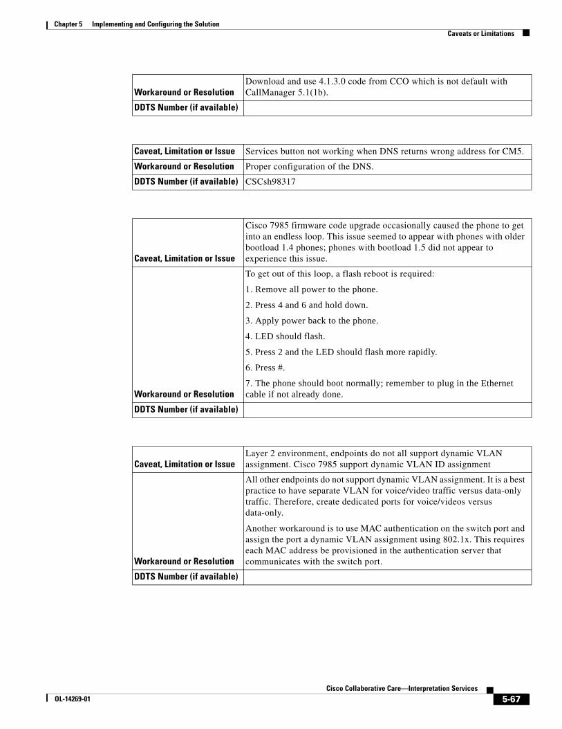
Chapter 5 Implementing and Configuring the SolutionCaveats or Limitations
Workaround or ResolutionDownload and use 4.1.3.0 code from CCO which is not default with CallManager 5.1(1b).
DDTS Number (if available)
Caveat, Limitation or Issue Services button not working when DNS returns wrong address for CM5.
Workaround or Resolution Proper configuration of the DNS.
DDTS Number (if available) CSCsh98317
Caveat, Limitation or Issue
Cisco 7985 firmware code upgrade occasionally caused the phone to get into an endless loop. This issue seemed to appear with phones with older bootload 1.4 phones; phones with bootload 1.5 did not appear to experience this issue.
Workaround or Resolution
To get out of this loop, a flash reboot is required:
1. Remove all power to the phone.
2. Press 4 and 6 and hold down.
3. Apply power back to the phone.
4. LED should flash.
5. Press 2 and the LED should flash more rapidly.
6. Press #.
7. The phone should boot normally; remember to plug in the Ethernet cable if not already done.
DDTS Number (if available)
Caveat, Limitation or IssueLayer 2 environment, endpoints do not all support dynamic VLAN assignment. Cisco 7985 support dynamic VLAN ID assignment
Workaround or Resolution
All other endpoints do not support dynamic VLAN assignment. It is a best practice to have separate VLAN for voice/video traffic versus data-only traffic. Therefore, create dedicated ports for voice/videos versus data-only.
Another workaround is to use MAC authentication on the switch port and assign the port a dynamic VLAN assignment using 802.1x. This requires each MAC address be provisioned in the authentication server that communicates with the switch port.
DDTS Number (if available)
5-67Cisco Collaborative Care—Interpretation Services
OL-14269-01
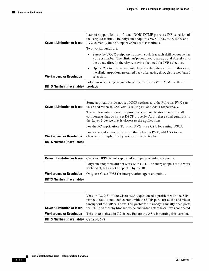
Chapter 5 Implementing and Configuring the SolutionCaveats or Limitations
Caveat, Limitation or Issue
Lack of support for out-of-band (OOB) DTMF prevents IVR selection of the scripted menus. The polycom endpoints VSX-3000, VSX-5000 and PVX currently do no support OOB DTMF methods.
Workaround or Resolution
Two workarounds are:
• Setup the UCCX script environment such that each skill set queue has a direct number. The clinician/patient would always dial directly into the queue directly thereby removing the need for IVR selection.
• Option 2 is to use the web interface to select the skillset. In this case, the clinician/patient are called back after going through the web based selection.
DDTS Number (if available)Polycom is working on an enhancement to add OOB DTMF to their products.
Caveat, Limitation or IssueSome applications do not set DSCP settings and the Polycom PVX sets voice and video to CS5 versus setting EF and AF41 respectively.
Workaround or Resolution
The implementation section provides a reclassification model for all components that do not set DSCP properly. Apply these configurations to the Layer 3 device that is closest to the applications.
For the PC application (Polycom PVX), use CSA for setting DSCP.
For voice and video traffic from the Polycom PVX, add CS5 to the classmap for high priority voice and video traffic.
DDTS Number (if available)
Caveat, Limitation or Issue CAD and IPPA is not supported with partner video endpoints.
Workaround or Resolution
Polycom endpoints did not work with CAD. Tandberg endpoints did work with CAD, but is not supported by the BU.
Only use Cisco 7985 for interpretation agent endpoints.
DDTS Number (if available)
Caveat, Limitation or Issue
Version 7.2.2(8) of the Cisco ASA experienced a problem with the SIP inspect that did not keep current with the UDP ports for audio and video throughout the SIP call flow. This problem did not dynamically open ports for UDP and thereby blocked voice and video after the call was connected.
Workaround or Resolution This issue is fixed in 7.2.2(10). Ensure the ASA is running this version.
DDTS Number (if available) CSCsh43698
5-68Cisco Collaborative Care—Interpretation Services
OL-14269-01

Chapter 5 Implementing and Configuring the SolutionCaveats or Limitations
Caveat, Limitation or Issue
On the Cisco ASA, a cosmetic bug exist for the display of the SIP trunk state. When the invite comes from one CallManager to another via ASA, the show sip session command shows the SIP Invite not Active State versus should be shown as connected state.
Workaround or Resolution No workaround.
DDTS Number (if available) CSCsh43799
Caveat, Limitation or Issue
In the case of a ASA failover, only failover for RTP sessions is currently supported. A future release will support SIP UDP stateful Failover Signaling Messages.
Workaround or Resolution Retry the call if a failure occurs during call setup.
DDTS Number (if available)
Caveat, Limitation or Issue
Cisco ASA is altering the ports for voice and video when a call is made from a H.323 Polycom PVX on one CallManager to another CallManager across a SIP trunk trying to reach a Cisco 7985. This problem does not always appear.
Workaround or Resolution ????
DDTS Number (if available) BUG has been opened.
Caveat, Limitation or Issue
For admission control on CallManager on Deployment Model 2, when one location holds the resources for devices and a second location holds the resources for the inter-cluster SIP trunk, the resources are not getting decremented from the available pool. This may cause the bandwidth to be over subscribed.
Workaround or ResolutionManage the resources or add additional bandwidth to the network if this occurs often.
DDTS Number (if available) BUG to be filed.
Caveat, Limitation or Issue
Polycom’s Upgrade.exe file does not automatically upgrade code from 8.5 to 8.6, which supports SCCP. To perform upgrade, the user must manually FTP into the VSX-3000 and VSX-5000 and issue a number of undocumented commands to begin the upgrade process. The manual process works fine, but requires special assistance from technical support or Internal Polycom representatives.
Workaround or Resolution Request for assistance from Polycom.
DDTS Number (if available) Problem has been communicated to Polycom.
5-69Cisco Collaborative Care—Interpretation Services
OL-14269-01

Chapter 5 Implementing and Configuring the SolutionCaveats or Limitations
Caveat, Limitation or Issue
After upgrading to 8.6 SCCP code on VSX-3000 and VSX-5000, DHCP on the Cisco corporate network no longer functions. DHCP via a Linksys router does work. This may be isolated to our DHCP deployment, but could cause customer impact if similar situations occur in the customer base. The root cause for this failure was not identified by Polycom.
Workaround or ResolutionThis problem will most likely not occur. If it does occur, work with your Polycom representative.
DDTS Number (if available)
Caveat, Limitation or IssuePolycom PVX cannot make calls without the power supplied through the AC Adaptor.
Workaround or Resolution Make sure to have power applied during call sessions.
DDTS Number (if available)
Caveat, Limitation or Issue
Polycom PVX All USB cameras used sent a high amount of video bandwidth regardless of the change in motion being captured. A still image video capture generated only slightly less than the video rates generated under high motion change.
Workaround or Resolution Provision adequate bandwidth when using Polycom PVX.
DDTS Number (if available)
Caveat, Limitation or Issue
On the product activation site for PVX, the website asks for a License Number and a Serial Number. However, the PVX does not have a serial number.
Workaround or ResolutionEnter the License Number provided for both fields, License Number and Serial Number, to generate the Key Code necessary to register the product.
DDTS Number (if available)
Caveat, Limitation or Issue
H.323 PVX cannot originate nor receive SUPPLEMENTARY VOICE services. Since the MTP is not recommended in this solution, the PVX cannot receive supplementary voice services like transfer.
Workaround or Resolution No workaround.
DDTS Number (if available)
5-70Cisco Collaborative Care—Interpretation Services
OL-14269-01

Chapter 5 Implementing and Configuring the SolutionCaveats or Limitations
Caveat, Limitation or Issue
Tandberg T1000 MXP currently uses M2.1 firmware on the phone. There is a bug with firewalls and the way that the code determines the UDP port for the RTP streams. This can cause problems when used through firewalls.
Workaround or Resolution Use M2.2 Beta version for Tandberg T1000 MXP.
DDTS Number (if available)
Caveat, Limitation or IssueTandberg T1000 MXP has not been complete certified for CM 5.1. This work is in progress.
Workaround or Resolution Work with your Tandberg representative or reseller.
DDTS Number (if available)
Caveat, Limitation or IssueThe Polycom and Tandberg icon are missing from the CallManager GUI for the device list.
Workaround or Resolution No workaround.
DDTS Number (if available) CSCsh98363
Caveat, Limitation or Issue
For admission control on CallManager on Deployment Model 2, when one location holds the resources for devices and a second location holds the resources for the inter-cluster SIP trunk, the resources are not getting decremented from the available pool. This may cause the bandwidth to be over subscribed.
Workaround or ResolutionManage the resources or add additional bandwidth to the network if this occurs often.
DDTS Number (if available) CSCsi13130
Caveat, Limitation or Issue
Cisco ASA is altering the ports for voice and video when a call is made from a H.323 Polycom PVX between one CallManager to another CallManager across a SIP trunk trying to reach a Cisco 7985. This problem does not always appear.
Workaround or Resolution No workaround with ASA
DDTS Number (if available) CSCsi13866
5-71Cisco Collaborative Care—Interpretation Services
OL-14269-01

Chapter 5 Implementing and Configuring the SolutionCaveats or Limitations
5-72Cisco Collaborative Care—Interpretation Services
OL-14269-01

Cisco OL-14269-01
A
P P E N D I X A Technology PrimerSign Language RequirementsThe use of this solution by deaf and/or hearing impaired requires certain performance metrics to provide an acceptable level of service. The performance metrics that most commonly come to mind are that of video resolution and frame rate. It is commonly accepted that video frame rates of 25fps or better at CIF resolution (352x288) or better is sufficient for sign language usage.
The camera exposure time is another video performance metric that is required to be kept as low as possible to prevent blurring of images. The recommendation is to keep the exposure time to 1/60 of a second faster. Any exposure time slower than this will result in motion blur, impacting the user from identifying certain characters and hand movements.
Another performance metric that must be considered for successful use is that of synchronization of the video and audio. In some instances, the hearing impaired person requires the use of both video and audio to successfully communicate. The audio channel is encoded using either the G.711 or G.722 audio codec. It is then transported across the network using a Real Time Protocol (RTP) stream that is separate from that of the video-based RTP stream. The video images are compressed using an MPEG4 encoder that may induce some level of delay that is greater then that of the audio codec. The recommended maximum delay between the audio and video streams should not exceed 100ms.
During our testing, we did not encounter any times when the two streams were out of synchronization, but do acknowledge that such a situation could occur due to a number of factors. To reduce the likelihood of this occurring, it is critical that QoS be applied for both the audio and video RTP streams. In some situations, the video endpoint may not mark the video/audio traffic using the DiffServe QoS model. In these situations, marking the traffic at the first capable point in the network is recommended. This assures that any additional network components downstream of the sending video endpoint can properly identify traffic as high priority.
Note The information between this note and the next note may need to be excluded due to copyright issues.
The International Telecommunications Union conducted a study to evaluate the affects of frame rate and screen resolution for deaf and hearing impaired users whom use sign language to communicate. The following chart is a summary of the recommendations what resulted form the study. The study can be found at http://www.itu.int/rec/T-REC-H.Sup1-199905-I/en.
To summarize, the ITU recommends frame rates greater then 25fps at CIF resolution. In cases where the frame rate was less then 25fps at CIF resolutions, interpretation may become impaired, especially when finger spelling of a word is necessary.
A-1Collaborative Care—Interpretation Services

Appendix A Technology PrimerVideo Specification
It is therefore recommended that in order to support Sign Language worst case, that of finger spelling, a frame rate of 25fps or better is required with an accompanying resolution of CIF (352x288) or better.
Figure A-1 Sign Language Usability
Note The information between this note and the previous note may need to be excluded due to copyright issues. See http://www.itu.int/rec/T-REC-H.Sup1-199905-I/en.
Video SpecificationA variety of codecs can be implemented with relative ease on PCs and in consumer electronics equipment. It is therefore possible for multiple codecs to be available in the same product, avoiding the need to choose a single dominant codec for compatibility reasons. In the end it seems unlikely that one codec will replace them all. Some widely-used video codecs are listed below, starting with a chronological-order list of the ones specified in international standards.
MPEG-4 Part 10 (a technically aligned standard with the ITU-T’s H.264 and often also referred to as AVC). This emerging new standard is the current state of the art of ITU-T and MPEG standardized compression technology, and is rapidly gaining adoption into a wide variety of applications. It contains a number of significant advances in compression capability, and it has recently been adopted into a number of company products, including for example the PlayStation Portable, iPod, the Nero Digital product suite, Mac OS X v10.4, as well as HD DVD/Blu-ray Disc.
CIF (Common Intermediate Format) is used to standardize the horizontal and vertical resolutions in pixels of YCbCr sequences in video signals. QCIF means “Quarter CIF.” SQCIF means “Sub-quarter CIF.”. These two formats are common in video encoding. To have one fourth of the area as “quarter” implies, height and width of the frame are halved. A CIF is commonly defined as one-quarter of the “full” resolution of the video system it is intended for (listed below as 4CIF). Note that this full resolution does not match what is currently referred to as D1 video (based upon Sony’s D1 format).
SQ SIF(112x96)
Q SIF(176x144)
CIF(352x288)
20
Good Usability
Fra
mes
Per
Sec
ond
Usable with SomeRestrictions
Very LimitedUsage
Not Usable
12
8
2207
88
A-2Cisco Collaborative Care—Interpretation Services
OL-14269-01

Appendix A Technology PrimerVideo Specification
The NTSC format is used with the M format (see broadcast television systems), which consists of 29.97 interlaced frames of video per second. Each frame consists of 484 lines out of a total of 525 (the rest are used for sync, vertical retrace, and other data such as captioning). PAL uses 625 lines, and so has a better picture quality. The NTSC system interlaces its scanlines, drawing odd-numbered scanlines in odd-numbered fields and even-numbered scanlines in even-numbered fields, yielding a nearly flicker-free image at its approximately 59.94 hertz (nominally 60 Hz/100.1%) refresh frequency. The refresh compares favorably to the 50 Hz refresh rate of the PAL and SECAM video formats used in Europe, where 50 Hz alternating current is the standard; flicker was more likely to be noticed when using these standards until modern PAL TV sets began using 100 Hz refresh rate to eliminate flicker. This produces a far more stable picture than native NTSC and PAL had, effectively displaying each frame twice. This did, at first, cause some motion problems, so it was not universally adopted until a few years ago. Interlacing the picture does complicate editing video, but this is true of all interlaced video formats, including PAL and SECAM.
PAL versus NTSCPAL format as it has greater resolution than NTSC, is generally better than the latter, especially for DVD movies.[2] NTSC receivers have a tint control to perform that correction manually. Some engineers jokingly expand NTSC to “Never Twice the Same Color” or “Not The Same Color” while referring to PAL as “Perfect At Last,” “Peace At Last,” or “Pay for Additional Luxury!”
However, the alternation of color information-Hanover bars-can lead to picture grain on pictures with extreme phase errors even in PAL systems, causing some engineers to alternatively expand PAL to “Picture Always Lousy” or “Pretty Awful Looking.”. Another expansion is “Pay Another Licence” in reference to the British television licence fee which is higher for color sets.
A PAL decoder can be seen as a pair of NTSC decoders:
• PAL can be decoded with two NTSC decoders.
• By switching between the two NTSC decoders every other line it is possible to decode PAL without a phase delay line or two phase PLL circuit.
Table A-1 CIF Video Resolutions (in Pixels)
FormatNTSC-based PAL-based
SQCIF
128 × 96
QCIF 176 × 120 176 × 144
QCIF+
176 × 220 176 × 220
CIF 352 × 240 352 × 288
2CIF 704 × 240 704 × 288
4CIF 704 × 480 704 × 576
9CIF 1056 × 720 1056 × 864
16CIF 1408 × 960 1408 × 1152
A-3Cisco Collaborative Care—Interpretation Services
OL-14269-01

Appendix A Technology PrimerVideo Specification
This works because one decoder receives a color subcarrier with negated phase in relation to the other decoder. It then negates the phase of that subcarrier when decoding. This leads to smaller phase errors being cancelled out. However a delay line PAL decoder gives superior performance. Some Japanese TVs originally used the dual NTSC method to avoid paying royalty to Telefunken. PAL and NTSC have slightly divergent color spaces, but the color decoder differences here are ignored.
The issue of frame rates and color subcarriers is ignored in this document. These technical details play no direct role (except as subsystems and physical parameters) to the decoding of the signal.
A-4Cisco Collaborative Care—Interpretation Services
OL-14269-01

Cisco OL-14269-01
A
P P E N D I X B Terms and AcronymsTerm or Acronym Definition
ACL (Access Control List) Method used on ASA firewalls to block unwanted traffic. A method called pinhole allows for IP address and UDP/TCP ports to be dynamically opened through the firewall. This function is required to dynamically allow video and audio streams through the firewall.
CAD (Cisco Agent Desktop) A software application that runs on a PC that allows the Interpretation Agent to manage the status of an Agent. There is an Agent desktop and Supervisor desktop that offers several functions.
Call Signalling Protocols that are sent between call devices that instruct call management instructions.
Cisco MGN Cisco Medical-Grade Network.
H.323 ITU-T protocol used between IP Phones, Gatekeepers, and Call Manager.
JTAPI Protocol used between UCCX and Call Manager to exchange call management information to handle the logic of Contact Center applications.
LIS (Language Interpretation Service)
A distributed, flexible video-based call center that provides healthcare providers with seamless access to language translators.
NAT (Network Address Translation) Method used to map private IP address used by Enterprise customer to public IP addresses used when traffic must traverse the internet. This function is often required for Business to Business data communication.
PAT (Port Address Translation) Method used to map multiple private IP address used by enterprise customer into a shared public IP address when “inside” traffic must traverse the internet. This function would be used in addition to NAT. When public IP address are limited, PAT can overcome that limitation.
SCCP/Skinny Protocol Cisco protocol used between IP phones and Call Manager.
SIP Protocol used in this solution for communication between Call Managers.
B-1Collaborative Care—Interpretation Services

Appendix B Terms and Acronyms
Video Codec Encoding technology to create video packets that represent the video streams which can be sent over an IP network. H.264, MPEG-4 Part 10 is a digital video codec that achieves high data compression while offering excellent video quality.
Voice Codec Encoding technology to create voice packets that represent voice streams which can be sent over an IP network. G.722 is an ITU-T standard wideband speech codec that samples audio at 16kHZ to provide superior audio quality and clarity.
Term or Acronym Definition
B-2Cisco Collaborative Care—Interpretation Services
OL-14269-01