cht-r series - onecallmedia.onecall.com/image_products/velodyne/cht-r20manual_english... ·...
TRANSCRIPT
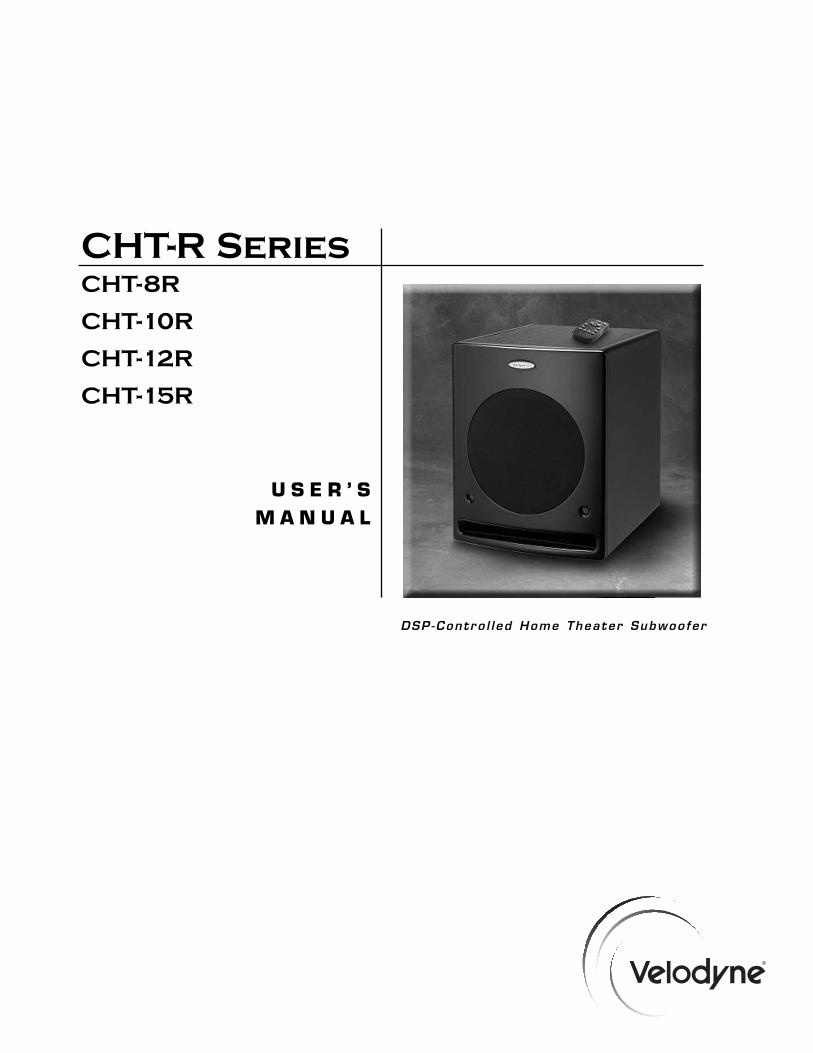
CHT-R SeriesCHT-8R
CHT-10R
CHT-12R
CHT-15R
U S E R ’ SM A N U A L
DSP-Contro l l ed Home Theater Subwoofer
i.w w w . v e l o d y n e . c o m CHT-R User’s Manual
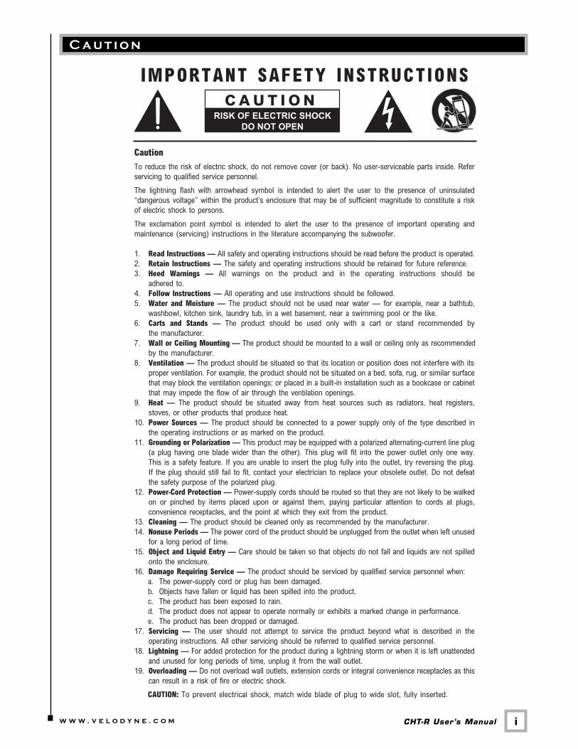
C a u t i o n
ii.w w w . v e l o d y n e . c o m CHT-R User’s Manual
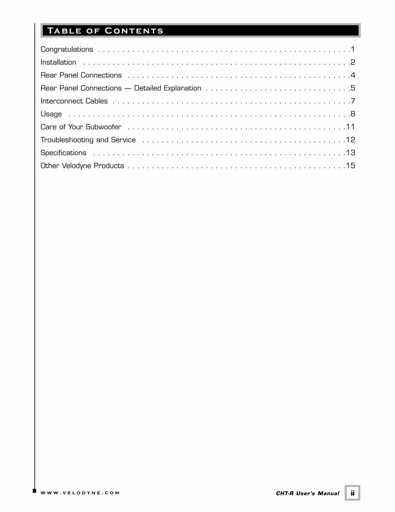
Ta b l e o f C o n t e n t s
Congratulations . . . . . . . . . . . . . . . . . . . . . . . . . . . . . . . . . . . . . . . . . . . . . . . . . . . .1
Installation . . . . . . . . . . . . . . . . . . . . . . . . . . . . . . . . . . . . . . . . . . . . . . . . . . . . . . .2
Rear Panel Connections . . . . . . . . . . . . . . . . . . . . . . . . . . . . . . . . . . . . . . . . . . . . . .4
Rear Panel Connections — Detailed Explanation . . . . . . . . . . . . . . . . . . . . . . . . . . . . . .5
Interconnect Cables . . . . . . . . . . . . . . . . . . . . . . . . . . . . . . . . . . . . . . . . . . . . . . . . .7
Usage . . . . . . . . . . . . . . . . . . . . . . . . . . . . . . . . . . . . . . . . . . . . . . . . . . . . . . . . . .8
Care of Your Subwoofer . . . . . . . . . . . . . . . . . . . . . . . . . . . . . . . . . . . . . . . . . . . . .11
Troubleshooting and Service . . . . . . . . . . . . . . . . . . . . . . . . . . . . . . . . . . . . . . . . . .12
Specifications . . . . . . . . . . . . . . . . . . . . . . . . . . . . . . . . . . . . . . . . . . . . . . . . . . . .13
Other Velodyne Products . . . . . . . . . . . . . . . . . . . . . . . . . . . . . . . . . . . . . . . . . . . . .15
C o n g r a t u l a t i o n s
1.w w w . v e l o d y n e . c o m CHT-R User’s Manual
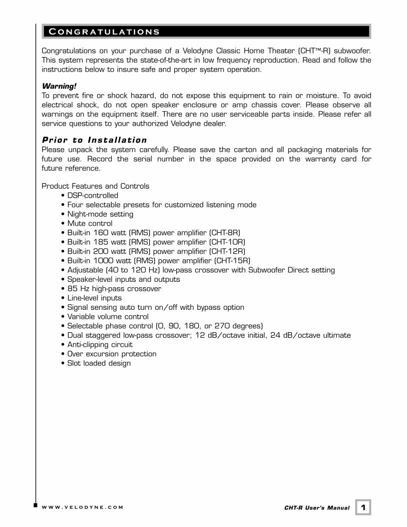
Congratulations on your purchase of a Velodyne Classic Home Theater (CHT™-R) subwoofer.This system represents the state-of-the-art in low frequency reproduction. Read and follow theinstructions below to insure safe and proper system operation.
Warning! To prevent fire or shock hazard, do not expose this equipment to rain or moisture. To avoidelectrical shock, do not open speaker enclosure or amp chassis cover. Please observe allwarnings on the equipment itself. There are no user serviceable parts inside. Please refer allservice questions to your authorized Velodyne dealer.
Pr ior to Insta l lat ion Please unpack the system carefully. Please save the carton and all packaging materials forfuture use. Record the serial number in the space provided on the warranty card forfuture reference.
Product Features and Controls • DSP-controlled • Four selectable presets for customized listening mode • Night-mode setting • Mute control • Built-in 160 watt (RMS) power amplifier (CHT-8R) • Built-in 185 watt (RMS) power amplifier (CHT-10R) • Built-in 200 watt (RMS) power amplifier (CHT-12R) • Built-in 1000 watt (RMS) power amplifier (CHT-15R) • Adjustable (40 to 120 Hz) low-pass crossover with Subwoofer Direct setting • Speaker-level inputs and outputs • 85 Hz high-pass crossover • Line-level inputs • Signal sensing auto turn on/off with bypass option • Variable volume control • Selectable phase control (0, 90, 180, or 270 degrees) • Dual staggered low-pass crossover; 12 dB/octave initial, 24 dB/octave ultimate • Anti-clipping circuit • Over excursion protection • Slot loaded design
I n s ta l l a t i o n
2.w w w . v e l o d y n e . c o m CHT-R User’s Manual
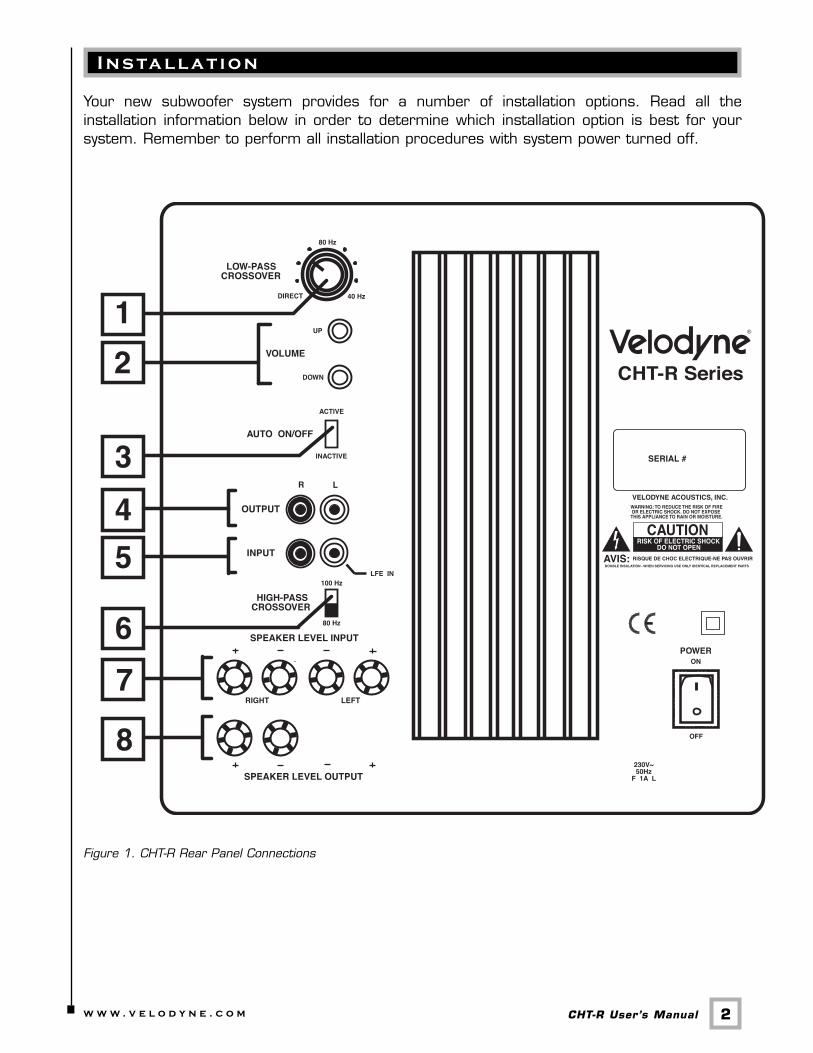
Your new subwoofer system provides for a number of installation options. Read all theinstallation information below in order to determine which installation option is best for yoursystem. Remember to perform all installation procedures with system power turned off.
Figure 1. CHT-R Rear Panel Connections
3.w w w . v e l o d y n e . c o m CHT-R User’s Manual
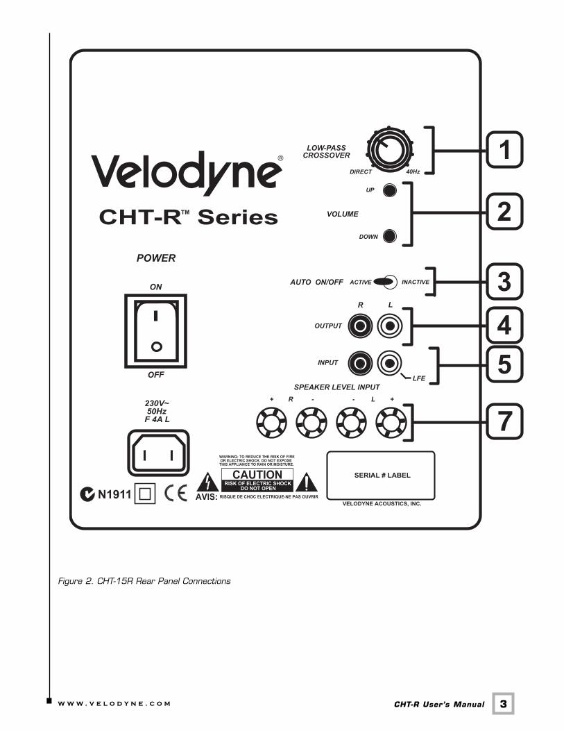
Figure 2. CHT-15R Rear Panel Connections
R e a r Pa n e l C o n n e c t i o n s
4.w w w . v e l o d y n e . c o m CHT-R User’s Manual
Figure 1 shows the connections on the rear panel of the CHT-8R, CHT-10R and CHT-12R.Figure 2 shows the connections on the rear panel of the CHT-15R.
Following are brief descriptions of the connections described in Figure 1 and 2. More detail onthese connections can be found on the next page.
(1) LOW-PASS CROSSOVERUse this knob to select the high-frequency range at which you wish to cut off the signal tothe subwoofer. When the knob is turned all the way to the left, the Subwoofer Direct featureis invoked and the subwoofer plays all frequencies up to 200 Hz.
(2) VOLUME Control This control allows you to balance the output from the subwoofer to the main speakers inyour system. This control should be set to achieve similar volume level from between boththe main speakers and subwoofer. When pressing volume up or down, the speed at whichthe power light blinks indicates subwoofer volume - the faster the blinking, the louder theunit plays. After the volume is changed (up or down), there will also be 2 sets of center LEDblinks. Slower blinks represent tens and faster blinks represent ones. If the LED blinks 3times, pauses, then blinks 6 times, this means that the volume is set at 36. The volumerange is from 1 to 99.
Note: Volume is also controllable by using the supplied remote, when defaults are restored.The default is 35 out of 100.
WARNING: Some manufacturers preset their receivers with the Sub-Out channel signalat a minimum level. It is very important to verify that your receiver Sub-Out channel is set tothe same output as your front right and left channels. Refer to your receiver manual for theindividual channel level adjustment procedure. If your receiver Sub-Out channel is set too low,the subwoofer may appear to have a weak output, it may sound noisy or distorted, and theAuto-On/Off feature may not work properly.
(3) AUTO ON/OFF Switch The Auto-On/Off feature allows the subwoofer to turn itself off when not in use.
- With the Auto-On/Off switch set to ACTIVE, the subwoofer will monitor its input, and ifthere is no signal present for approximately 15 minutes, it will shut down and go intostandby mode. As soon as a signal is present again, the subwoofer will immediately turnitself back on.
- With the Auto-On/Off switch set to INACTIVE, the auto-on/off feature is bypassed. Thesubwoofer will remain on until the power switch is turned off.
WARNING: If the Sub-Out channel signal level from your receiver is too weak, this featurewill not operate properly. See Volume Control section (above).
(4) LINE OUTPUTConnect these jacks to the LINE IN preamp input to use the CHT-R’s internal high passcrossover. See below for a more detailed explanation of this crossover.
(5) LINE INPUT/LFE InputConnect these jacks to the LINE OUT preamp output, LFE output, or subwoofer output jacksof your receiver/processor. If using the LFE output from your receiver or processor, plugthe single cable into the “L”– LFE input or, for more signal, use a “Y” connector and feed thesignal into both “R” and “L” inputs.
(6) HIGH PASS CROSSOVER SwitchThis switch selects the frequency for the high pass crossover. This crossover is functionalon both line and speaker-level outputs. Smaller speakers with limited low frequency outputmay perform better using the higher 100 Hz setting that will reduce the low frequenciessent to them. Larger speakers with greater low frequency output may be able to handle the80 Hz setting without strain.
(7) SPEAKER LEVEL INPUT TerminalsConnect these input terminals to the speaker output terminals of your amplifier or receiver.If you use this method of connection, when you go to the receiver speaker set up menu,make sure you select the large speaker option.
(8) SPEAKER LEVEL OUTPUT TerminalsSends a crossed-over speaker-level signal to the front speakers. See below for a moredetailed explanation of this crossover.
Your new subwoofer is equipped with both speaker-level and line-level inputs. Use theRCA/Phono type “INPUT” jacks when connecting your subwoofer to a pre-amp, signalprocessor, or line-level crossover. The “SPEAKER LEVEL INPUT” jacks connect directly to thespeaker outputs of an integrated amplifier or receiver. Your amplifier section will notice noadditional loading effects when you use these inputs because of their high impedance.
Note: Do not use both the RCA/Phono “INPUT” connections and “SPEAKER LEVEL INPUT”connections simultaneously.
Low-Pass Crossover Both sets of inputs sum the left and right channels together and the resulting signal is passedthrough an adjustable low-pass crossover before being amplified. The crossover control allowsyou to adjust the upper limit of the subwoofer’s frequency response from 40 to 120 Hz. Thesubwoofer’s response will begin rolling off above the frequency you set this control to.
You should set the crossover frequency to obtain a smooth and seamless transition from thesubwoofer to the main speakers in your system. If your main speakers are smaller units withlimited low frequency output, you may wish to choose a higher frequency (such as 100 -120Hz) than you would with larger speakers which have greater low frequency output. With largerspeakers, you might start with this control set lower, such as 80 Hz.
R e a r Pa n e l C o n n e c t i o n s — D e ta i l e d E x p l a n a t i o n
5.w w w . v e l o d y n e . c o m CHT-R User’s Manual
6.w w w . v e l o d y n e . c o m CHT-R User’s Manual
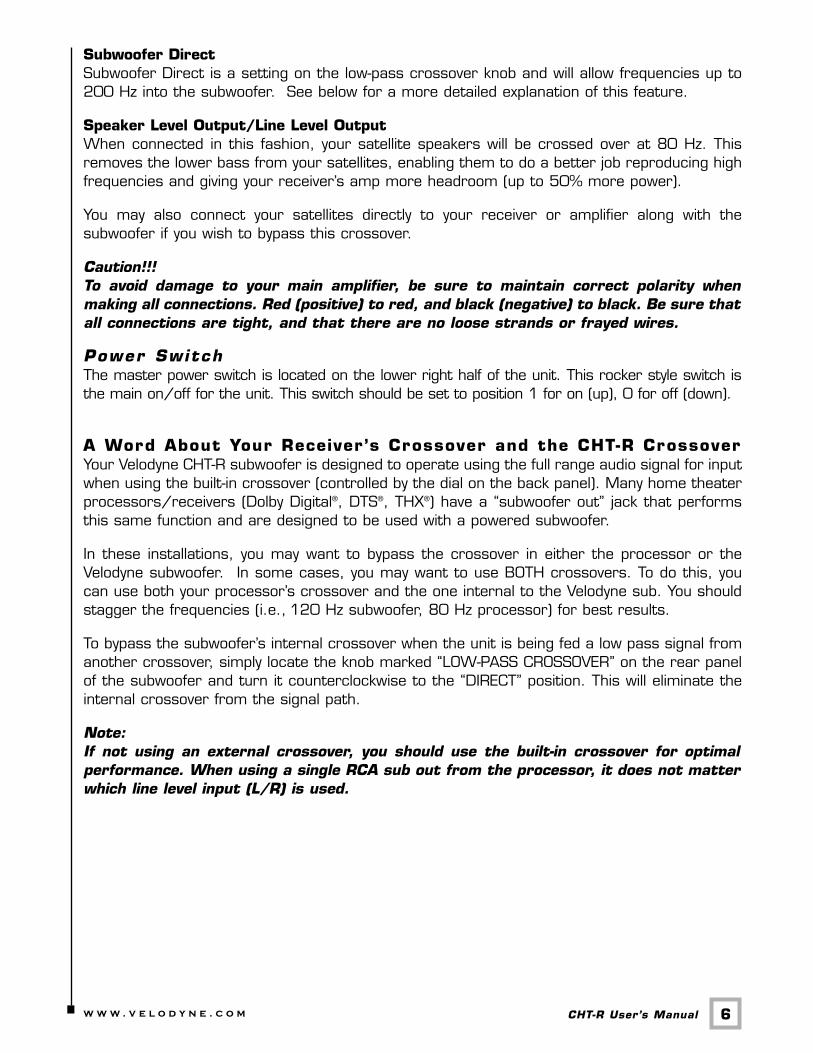
Subwoofer DirectSubwoofer Direct is a setting on the low-pass crossover knob and will allow frequencies up to200 Hz into the subwoofer. See below for a more detailed explanation of this feature.
Speaker Level Output/Line Level OutputWhen connected in this fashion, your satellite speakers will be crossed over at 80 Hz. Thisremoves the lower bass from your satellites, enabling them to do a better job reproducing highfrequencies and giving your receiver’s amp more headroom (up to 50% more power).
You may also connect your satellites directly to your receiver or amplifier along with thesubwoofer if you wish to bypass this crossover.
Caution!!! To avoid damage to your main amplifier, be sure to maintain correct polarity whenmaking all connections. Red (positive) to red, and black (negative) to black. Be sure thatall connections are tight, and that there are no loose strands or frayed wires.
Power SwitchThe master power switch is located on the lower right half of the unit. This rocker style switch isthe main on/off for the unit. This switch should be set to position 1 for on (up), 0 for off (down).
A Word About Your Receiver’s Crossover and the CHT-R Crossover Your Velodyne CHT-R subwoofer is designed to operate using the full range audio signal for inputwhen using the built-in crossover (controlled by the dial on the back panel). Many home theaterprocessors/receivers (Dolby Digital®, DTS®, THX®) have a “subwoofer out” jack that performsthis same function and are designed to be used with a powered subwoofer.
In these installations, you may want to bypass the crossover in either the processor or theVelodyne subwoofer. In some cases, you may want to use BOTH crossovers. To do this, youcan use both your processor’s crossover and the one internal to the Velodyne sub. You shouldstagger the frequencies (i.e., 120 Hz subwoofer, 80 Hz processor) for best results.
To bypass the subwoofer’s internal crossover when the unit is being fed a low pass signal fromanother crossover, simply locate the knob marked “LOW-PASS CROSSOVER” on the rear panelof the subwoofer and turn it counterclockwise to the “DIRECT” position. This will eliminate theinternal crossover from the signal path.
Note: If not using an external crossover, you should use the built-in crossover for optimalperformance. When using a single RCA sub out from the processor, it does not matterwhich line level input (L/R) is used.
I n t e r c o n n e c t C a b l e s
7.w w w . v e l o d y n e . c o m CHT-R User’s Manual
When installing your new Velodyne subwoofer using the line-level connections, you should alwaysuse shielded phono cables. There are many decent cables available today, most any of whichwill work perfectly well. We do recommend that you keep the length of cable as short aspossible to avoid any potential noise problems.
When using speaker level connections, use a quality speaker cable that mates well with theconnectors (at least 14-gauge). Be very careful to avoid any loose or frayed strands that couldresult in a short, causing a dangerous condition and possible damage to your unit. Cables ofextremely large size are typically not required. Extremely large gauge wire may not properly fitin the binding posts, resulting in a poor connection and possible short circuits.
PlacementTrue subwoofers operate at extremely low frequencies, which are primarily omni-directional.While it is recommended that the subwoofers be placed on the same plane as the satellitespeakers, room and system conditions often dictate otherwise. Keep in mind that frequencyresponse and output level can be drastically influenced by placement, depending on the acousticproperties of your listening room. Typically, the optimum location for a subwoofer is in a frontcorner of your listening room. This location will usually offer the greatest output levels andoptimum low frequency extension. The worst location for a subwoofer is typically far away fromany walls, close to the center of your room and near an opening or door way. Avoid theselocations when possible. When using a pair of Velodyne subwoofers in stereo, it is preferableto place each subwoofer near the satellite of the same channel. Typically, a minimum distanceof one to two feet from your TV to the subwoofer will be adequate to avoid anymagnetic interference.
Caution! This subwoofer has electronics built into the cabinet. Do not place the cabinet next tosources of heat such as furnace registers, radiators, etc. Do not place the unit nearsources of excessive moisture, such as evaporative coolers, humidifiers, etc. The powercord should be routed in such a way that it will not be walked on, pinched, orcompressed in any way that could result in damaging the insulation or wire.
U s a g e
8.w w w . v e l o d y n e . c o m CHT-R User’s Manual
This section addresses day-to-day usage of your CHT-R subwoofer.
Remote Contro l
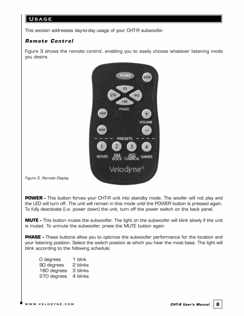
Figure 3 shows the remote control, enabling you to easily choose whatever listening modeyou desire.
Figure 3. Remote Display
POWER - This button forces your CHT-R unit into standby mode. The woofer will not play andthe LED will turn off. The unit will remain in this mode until the POWER button is pressed again.To fully deactivate (i.e. power down) the unit, turn off the power switch on the back panel.
MUTE - This button mutes the subwoofer. The light on the subwoofer will blink slowly if the unitis muted. To unmute the subwoofer, press the MUTE button again.
PHASE - These buttons allow you to optimize the subwoofer performance for the location andyour listening position. Select the switch position at which you hear the most bass. The light willblink according to the following schedule:
0 degrees 1 blink 90 degrees 2 blinks 180 degrees 3 blinks 270 degrees 4 blinks
9.w w w . v e l o d y n e . c o m CHT-R User’s Manual
LIGHT - If you wish, you can deactivate the power light on your CHT-R unit. To do this, pressthe LIGHT button on your remote. The light will turn off. To reactivate the light, press the LIGHTbutton again.
NIGHT - Night mode limits the maximum output of the subwoofer for later night listening or tobe more considerate of close neighbors. Press the night button to turn the night mode featureon or off. Night mode, when active, is indicated by the reduced intensity of the light.
VOLUME CONTROL - This control allows you to balance the output from the subwoofer to themain speakers in your system. This control should be set to achieve similar volume level frombetween both the main speakers and subwoofer. When pressing volume up or down, the speedat which the power light blinks indicates subwoofer volume - the faster the blinking, the louderthe unit plays. Slower blinks represent tens and faster blinks represent ones. After the volumeis changed (up or down) there will also be 2 sets of center LED blinks. If the LED blinks 3 times,pauses, then blinks 6 times, this means that the volume is set at 36. The volume range is from1 to 99.
Note: The volume can also be adjusted via the buttons on the back panel of the subwoofer.These buttons have the same effect as pressing the up and down volume buttons on yourremote.
WARNING: Some manufacturers preset their receivers with the Sub-Out channel signal at aminimum level. It is very important to verify that your receiver Sub-Out channel is set to thesame output as your front right and left channels. Refer to your receiver manual for theindividual channel level adjustment procedure. If your receiver Sub-Out channel is set too low,the subwoofer may appear to have a weak output, it may sound noisy or distorted, and the Auto-On/Off feature may not work properly.
PRESETS - There are four presets, consisting of Movies, R&B – Rock, Jazz – Classical, andGames. As a preset is chosen, the light flashes the corresponding number of times. Thepresets provide the following characteristics for bass reproduction:
Movies: Maximum output and impact for explosionsand other action adventure movie content.
R&B – Rock: Provides the driving bass found in today’s rock music.
Jazz – Classical: The tightest, cleanest, lowest distortion bass.
Games: Maximum loudness available for the impact of video games.
10.w w w . v e l o d y n e . c o m CHT-R User’s Manual
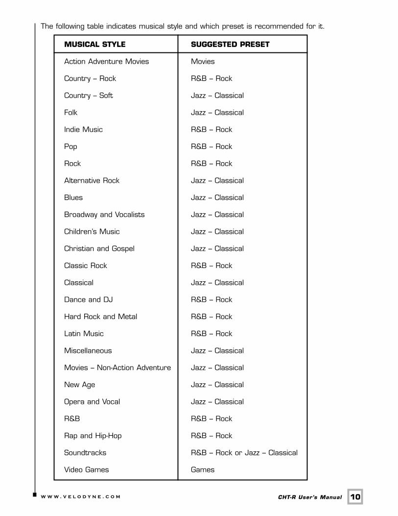
The following table indicates musical style and which preset is recommended for it.
MUSICAL STYLE SUGGESTED PRESET
Action Adventure Movies Movies
Country – Rock R&B – Rock
Country – Soft Jazz – Classical
Folk Jazz – Classical
Indie Music R&B – Rock
Pop R&B – Rock
Rock R&B – Rock
Alternative Rock Jazz – Classical
Blues Jazz – Classical
Broadway and Vocalists Jazz – Classical
Children’s Music Jazz – Classical
Christian and Gospel Jazz – Classical
Classic Rock R&B – Rock
Classical Jazz – Classical
Dance and DJ R&B – Rock
Hard Rock and Metal R&B – Rock
Latin Music R&B – Rock
Miscellaneous Jazz – Classical
Movies – Non-Action Adventure Jazz – Classical
New Age Jazz – Classical
Opera and Vocal Jazz – Classical
R&B R&B – Rock
Rap and Hip-Hop R&B – Rock
Soundtracks R&B – Rock or Jazz – Classical
Video Games Games
11.w w w . v e l o d y n e . c o m CHT-R User’s Manual
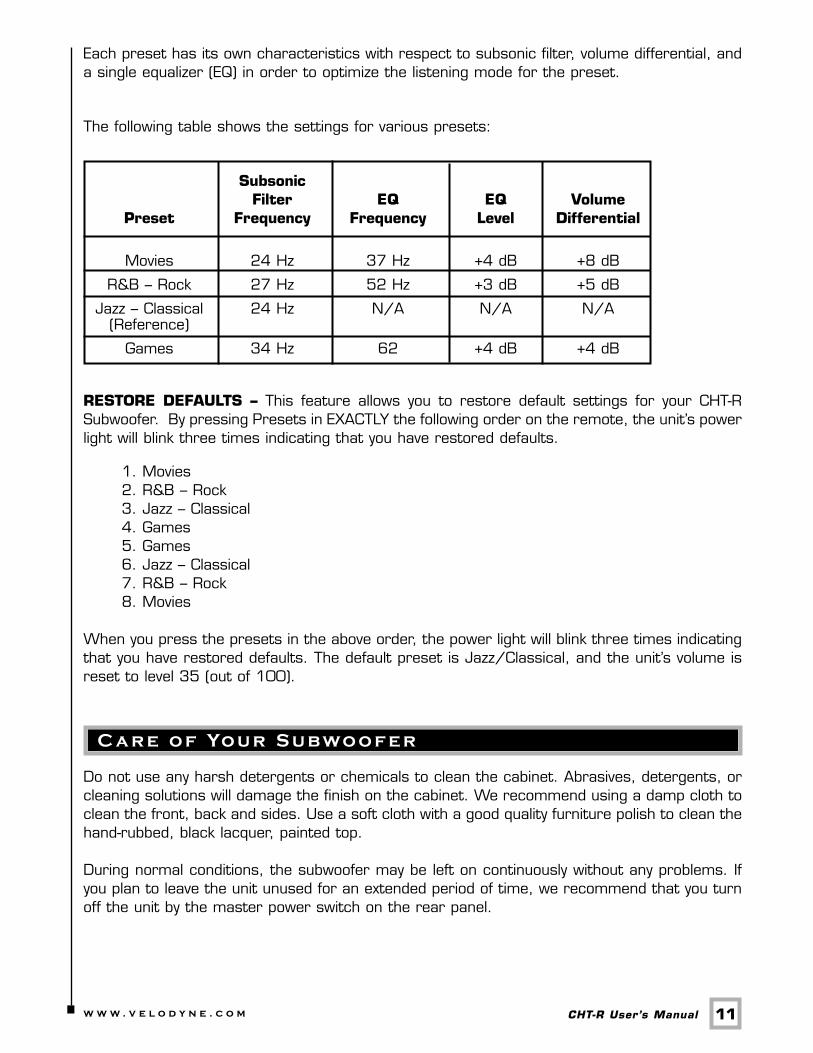
Each preset has its own characteristics with respect to subsonic filter, volume differential, anda single equalizer (EQ) in order to optimize the listening mode for the preset.
The following table shows the settings for various presets:
Subsonic Filter EQ EQ Volume
Preset Frequency Frequency Level Differential
Movies 24 Hz 37 Hz +4 dB +8 dB
R&B – Rock 27 Hz 52 Hz +3 dB +5 dB
Jazz – Classical 24 Hz N/A N/A N/A(Reference)
Games 34 Hz 62 +4 dB +4 dB
RESTORE DEFAULTS – This feature allows you to restore default settings for your CHT-RSubwoofer. By pressing Presets in EXACTLY the following order on the remote, the unit’s powerlight will blink three times indicating that you have restored defaults.
1. Movies 2. R&B – Rock 3. Jazz – Classical 4. Games 5. Games 6. Jazz – Classical 7. R&B – Rock 8. Movies
When you press the presets in the above order, the power light will blink three times indicatingthat you have restored defaults. The default preset is Jazz/Classical, and the unit’s volume isreset to level 35 (out of 100).
Do not use any harsh detergents or chemicals to clean the cabinet. Abrasives, detergents, orcleaning solutions will damage the finish on the cabinet. We recommend using a damp cloth toclean the front, back and sides. Use a soft cloth with a good quality furniture polish to clean thehand-rubbed, black lacquer, painted top.
During normal conditions, the subwoofer may be left on continuously without any problems. Ifyou plan to leave the unit unused for an extended period of time, we recommend that you turnoff the unit by the master power switch on the rear panel.
C a r e o f Yo u r S u b wo o f e r
T r o u b l e s h o o t i n g a n d S e rv i c e
12.w w w . v e l o d y n e . c o m CHT-R User’s Manual
Before seeking service for your subwoofer, please re-check all systems. Following is a simpletroubleshooting guide to assist you.
1. Verify that the unit is plugged in and power outlet used is active. 2. Is the power switch on? 3. Is unit receiving an input signal from your source? 4. Have all controls on subwoofer (volume, crossover, phase, etc.) been properly set? 5. If unit has been running at high levels, one of the protection circuits may be engaged.
Has the built-in amplifier overheated? 6. Has the power button been depressed on the remote?7. Is the remote non-responsive? We recommend replacing the batteries in the remote.
If the protection circuitry is active, the unit may cycle on and off until operating parametersreturn to normal. Under more serious conditions, the unit may shut off completely. Normaloperation will return upon cooling, but you may be required to turn the power off and then onagain to reset the unit.
The following conditions require service by a qualified technician:
1. The power cord has become damaged. 2. The unit does not appear to operate normally or exhibits
a marked change in performance. 3. The unit has been exposed to water. 4. Some part of the cabinet or circuitry is physically damaged.
Thank You for Purchasing a Velodyne!
S p e c i f i c a t i o n s
13.w w w . v e l o d y n e . c o m CHT-R User’s Manual
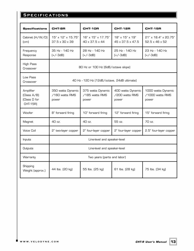
Specifications CHT-8R CHT-10R CHT-12R CHT-15R
Cabinet (H/W/D) 15” x 12” x 15.75” 16” x 15” x 17.75” 18” x 15” x 19” 21” x 18.4” x 20.75”
(cm) 37.5 x 30 x 39 40 x 37.5 x 44 45 x 37.5 x 47.5 52.5 x 46 x 52
Frequency 35 Hz - 140 Hz 28 Hz - 140 Hz 25 Hz - 140 Hz 23 Hz - 140 Hz
Response (+/-3dB) (+/-3dB) (+/-3dB) (+/-3dB)
High Pass 80 Hz or 100 Hz (6dB/octave slope)Crossover
Low Pass 40 Hz - 120 Hz (12dB/octave, 24dB ultimate)Crossover
Amplifier 350 watts Dynamic 375 watts Dynamic 400 watts Dynamic 1000 watts Dynamic
(Class A/B) /160 watts RMS /185 watts RMS /200 watts RMS /1000 watts RMS
(Class D for power power power power
CHT-15R)
Woofer 8” forward firing 10” forward firing 12” forward firing 15” forward firing
Magnet 40 oz. 40 oz. 55 oz. 70 oz.
Voice Coil 2” two-layer copper 2” four-layer copper 2” four-layer copper 2.5” four-layer copper
Inputs Line-level and speaker-level
Outputs Line-level and speaker-level
Warranty Two years (parts and labor)
Shipping44 lbs. (20 kg) 55 lbs. (25 kg) 61 lbs. (28 kg) 75 lbs. (34 kg)Weight (approx.)
14.w w w . v e l o d y n e . c o m CHT-R User’s Manual
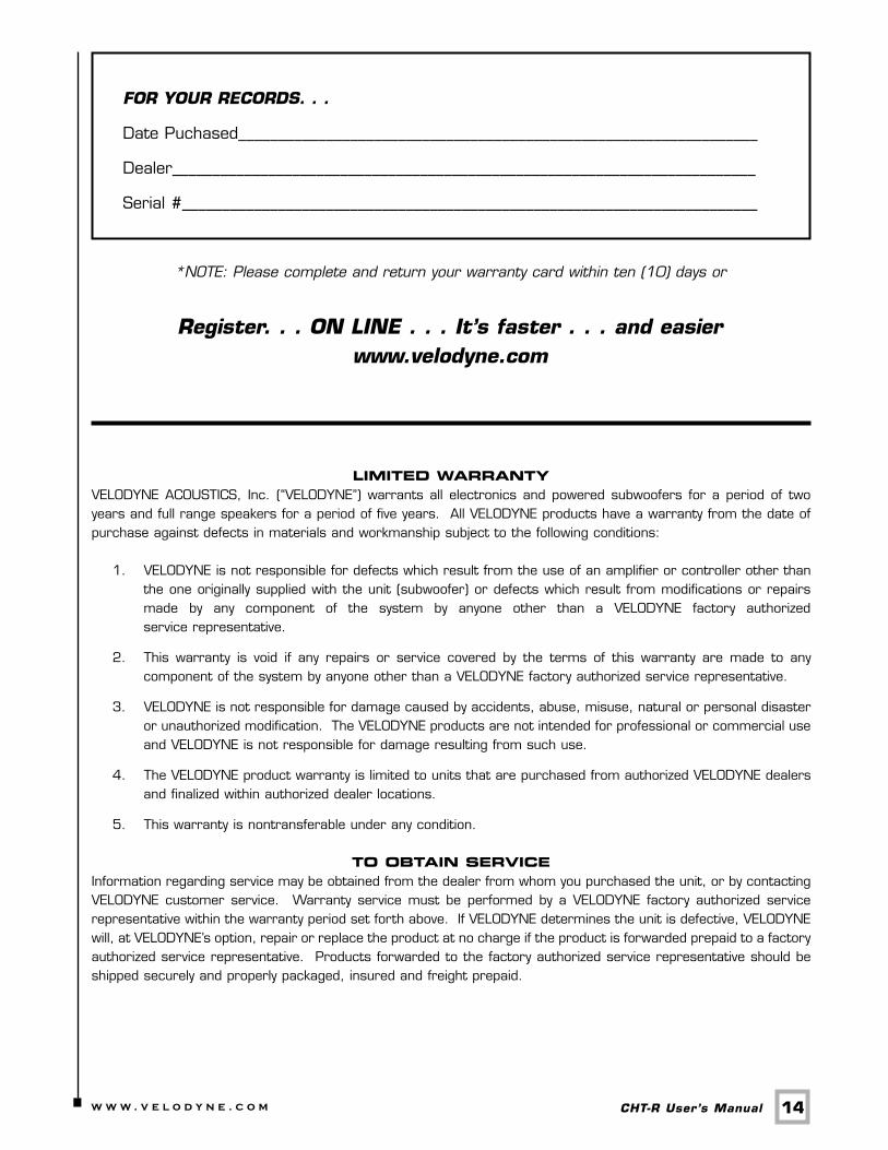
FOR YOUR RECORDS. . .
Date Puchased_________________________________________________________________
Dealer_________________________________________________________________________
Serial #________________________________________________________________________
*NOTE: Please complete and return your warranty card within ten (10) days or
Register. . . ON LINE . . . It’s faster . . . and easierwww.velodyne.com
LIMITED WARRANTYVELODYNE ACOUSTICS, Inc. (“VELODYNE”) warrants all electronics and powered subwoofers for a period of twoyears and full range speakers for a period of five years. All VELODYNE products have a warranty from the date ofpurchase against defects in materials and workmanship subject to the following conditions:
1. VELODYNE is not responsible for defects which result from the use of an amplifier or controller other thanthe one originally supplied with the unit (subwoofer) or defects which result from modifications or repairsmade by any component of the system by anyone other than a VELODYNE factory authorizedservice representative.
2. This warranty is void if any repairs or service covered by the terms of this warranty are made to anycomponent of the system by anyone other than a VELODYNE factory authorized service representative.
3. VELODYNE is not responsible for damage caused by accidents, abuse, misuse, natural or personal disasteror unauthorized modification. The VELODYNE products are not intended for professional or commercial useand VELODYNE is not responsible for damage resulting from such use.
4. The VELODYNE product warranty is limited to units that are purchased from authorized VELODYNE dealersand finalized within authorized dealer locations.
5. This warranty is nontransferable under any condition.
TO OBTAIN SERVICEInformation regarding service may be obtained from the dealer from whom you purchased the unit, or by contactingVELODYNE customer service. Warranty service must be performed by a VELODYNE factory authorized servicerepresentative within the warranty period set forth above. If VELODYNE determines the unit is defective, VELODYNEwill, at VELODYNE’s option, repair or replace the product at no charge if the product is forwarded prepaid to a factoryauthorized service representative. Products forwarded to the factory authorized service representative should beshipped securely and properly packaged, insured and freight prepaid.
15.w w w . v e l o d y n e . c o m CHT-R User’s Manual
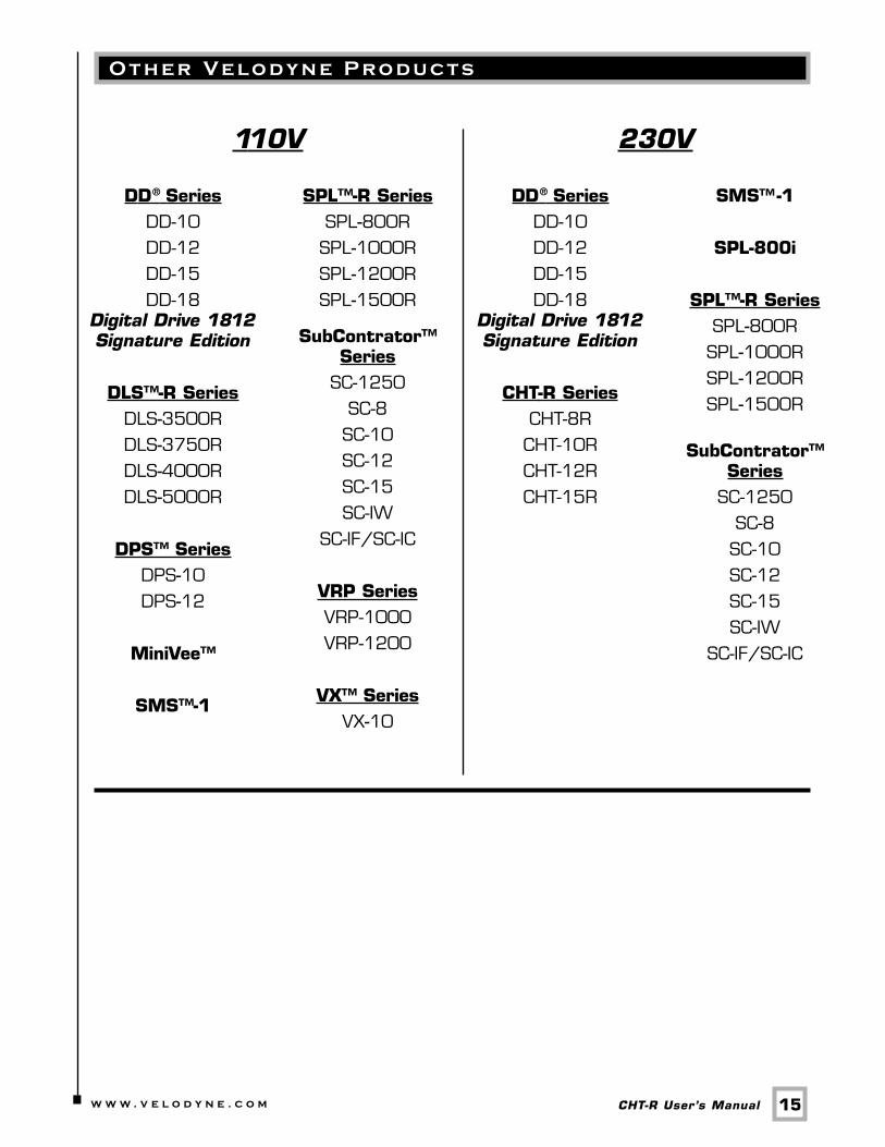
O t h e r Ve l o d y n e P r o d u c t s
DD SeriesDD-10DD-12DD-15DD-18
Digital Drive 1812Signature Edition
DLS™-R SeriesDLS-3500RDLS-3750RDLS-4000RDLS-5000R
DPS™ SeriesDPS-10DPS-12
MiniVee™
SMS™-1
110V
SPL™-R SeriesSPL-800RSPL-1000RSPL-1200RSPL-1500R
SubContrator™Series
SC-1250SC-8SC-10SC-12SC-15SC-IW
SC-IF/SC-IC
VRP SeriesVRP-1000VRP-1200
VX™ SeriesVX-10
DD SeriesDD-10DD-12DD-15DD-18
Digital Drive 1812Signature Edition
CHT-R SeriesCHT-8RCHT-10RCHT-12RCHT-15R
230V
SMS™-1
SPL-800i
SPL™-R SeriesSPL-800RSPL-1000RSPL-1200RSPL-1500R
SubContrator™Series
SC-1250SC-8SC-10SC-12SC-15SC-IW
SC-IF/SC-IC
® ®
16.w w w . v e l o d y n e . c o m CHT-R User’s Manual
Velodyne Acoustics, Inc.345 Digital Drive
Morgan Hill, CA 95037
408.465.2800 voice408.779.9227 fax
408.779.9208 service fax
www.velodyne.comService E-mail: [email protected] E-mail: [email protected]
Technical E-mail: [email protected]
63-CHTR Rev D NOV06