chapter four current, resistance, and electromotive force
TRANSCRIPT

Chapter Four
Current, Resistance and Resistivity
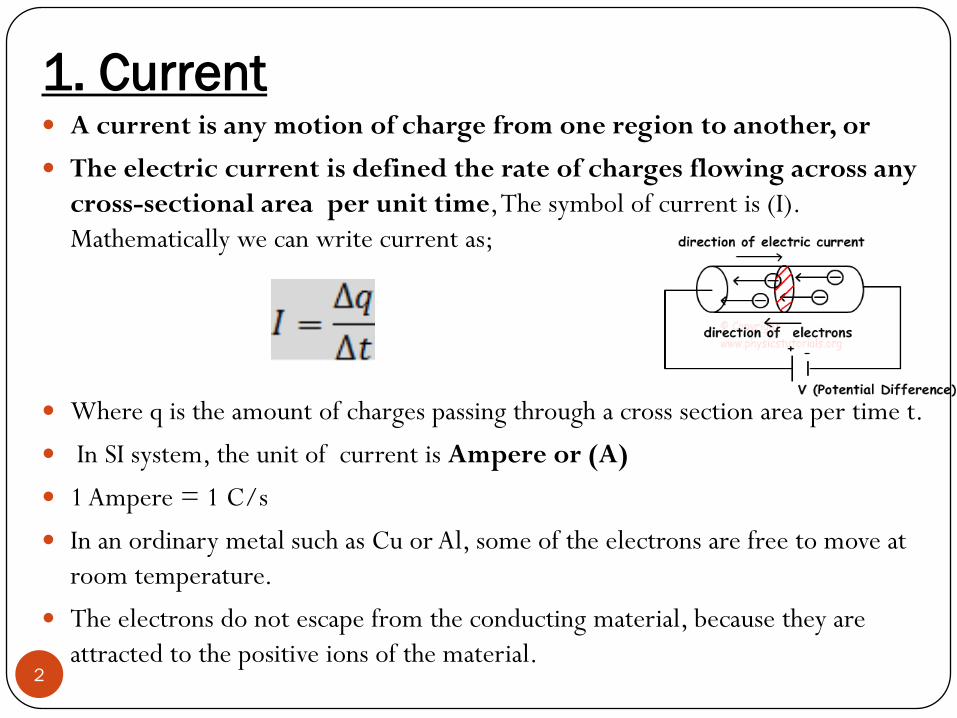
1. Current A current is any motion of charge from one region to another, or
The electric current is defined the rate of charges flowing across any
cross-sectional area per unit time, The symbol of current is (I).
Mathematically we can write current as;
Where q is the amount of charges passing through a cross section area per time t.
In SI system, the unit of current is Ampere or (A)
1 Ampere = 1 C/s
In an ordinary metal such as Cu or Al, some of the electrons are free to move at
room temperature.
The electrons do not escape from the conducting material, because they are
attracted to the positive ions of the material.2

Continue
3
A metal conductor distributes its free charges randomly where it is not
under any external force.
When the metal is connected to a source of a voltage, the free charges will
align themselves into a certain direction under the effect the electric field.
Current I drives itself opposite to the direction of free electrons through
out the circuit.

Continue
4
Burn that in mind, in metals, the only charges which responsible
of connection are free electrons (negative charges).
However, in semiconducting materials, such as a doped Silicon, both
holes (positive charges) and electrons (negative charges) are
responsible of connecting electricity.

2. A Simple Way To Produce Current By forming Positive And
Negative Charges
Part of the electric circuit that includes this light bulb passes through a beaker with a solution of
sodium chloride. The current in the solution is carried by both positive charges ions and negative
charges (Cl- ions). (Na+)5

3. Some methods to generate current (electricity)
Solar cells
Wind
Power
Electric
generator 6

4. Types of current
There are two types of electric current: Direct current
(DC) and Alternating current (AC).
In DC, The electrons flow in one direction continuously. An example
of DC is the current produced by a battery.
In AC, The electrons flow in two different directions (fist forward
and then backward). An example of AC is the current produced by
the electric generator.
We can plot the AC and DC graphs as below:
7

5. Sources of DC and AC
DC sources such as: solar cells, batteries and capacitors.
AC source such as: electric generator.
Most of the devices accept AC as the main current entrance.
However, the apertures inside them such as capacitors work with DC.
As a result, current must be converted into DC inside the devices.
Some other devices accept AC and DC at the same time, for example,
radio and TV.
Some other devices accept AC only and they work under that type of
current. examples are refrigerators and air-conditions.
For a source like solar cells, an invertors is needed to invert the DC
to AC, then transfer the current to the division centres.
8

6. Electric resistance and ohm’s law
The German scientist Georg Ohm was the first one discovered that
there is a linear relationship between Current and Voltage.
Ohm’s law states that the current I passing through a material
connected to an energy source V is given by the equation;
I = V/R.
R is the constant of proportionality and is called
electrical resistance.
The unit of resistance is OHM (Ω).
A material with a very large value of R will pass almost no current
(electrical insulator), while another material with very small R will
yield a large current for the same voltage (good electrical conductor).
9

Continue:
Resistor: is a device used in electronic circuit aimed to protect some
other elements from collapse. It can perform that via controlling the
current passing through elements.
This ability is called resistance.
Resistors can come in different
types and shapes.
The symbols of resistors are;
Resistance is the degree of opposition to the flow of electrons in a
material.
10

Ohm’s law curves
11

7. Resistivity
12
As It was mentioned, the relation between current and voltage changes with a proportion called resistance. Now we have to see how resistance changes as a function of the length and the area of the material where current passes though it.
Resistance can be compared to a traffic jam. More car makes the way harder to drive, and visa-versa is true.
For a longer metal conductor, the incoming charges will face a higher columbic force due to facing more charge carriers which they appose the movable charges to drive into a certain direction at the same time.
This means that resistance (R) proportion directly with the metal length (l)
This is, however, for wider road, easer to drive. Means that resistance proportion inversely with the Area (A) passing through it.
We can connect these three parameters (R), (L) and (A) in one formula called resistivity.

Continue
13
Note: the unite of resistivity is ohm.meter (Ωm).
Or we can say ….. (eq1)
HW:
From the equation 1 above, prove that the unit of resistance (R) is Ω.
Continue
14
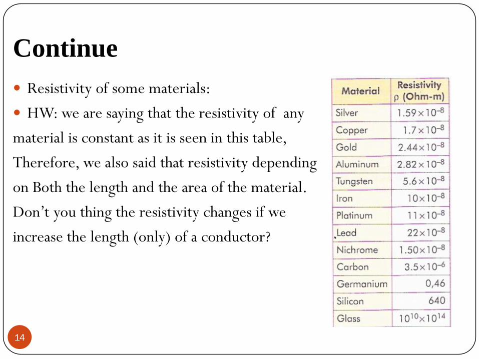
Resistivity of some materials:
HW: we are saying that the resistivity of any
material is constant as it is seen in this table,
Therefore, we also said that resistivity depending
on Both the length and the area of the material.
Don’t you thing the resistivity changes if we
increase the length (only) of a conductor?

Example 1
15
Example 2

8. Connecting resistors in series
The two resistors R1 and R2 can be connected in series to a voltage source ΔV. By current conservation, the same current I is flowing through each resistors.
The total voltage drop from a to c across both elements is the sum of the voltage drops across the individual resistors:
The two resistors in series can be replaced by one equivalent resistor Req .
The total (equivalent) resistance of the circuit is larger than the each of the resistors at the circuit. 16

9. Connecting resistors in parallel
let’s consider two resistors R1 and R2 that are connected in parallel
across a voltage source.
By current conversion, the current I that passes through the voltage
source must be divided into a current I1 that passes through resistor
R1 and current I2 that passes through resistor R2.
Each resistor individually satisfies ohm’s law:
And
17

10. Internal Resistance
18
The potential difference across a real source in a circuit is not equal to
the emf. The reason is that where charges moving through a material of
any real source encounters resistance. We call this the internal resistance
of the source, denoted by (r).
If this resistance behaves according to Ohm’s law, r is constant and
independent of the current I. As the current moves through, it
experiences an associated drop in potential equal to Ir.
Thus, when a current is flowing through a source from the negative
terminal (b) to the positive terminal (a), the potential difference
between the terminals is:

11. Work done by electric current and its power
19
For a circuit connected with a battery, charges need to be transferred
from one terminal of the battery to another. For that purpose, the
work is required which is:
Power: the electric energy decapitated in a resistor per unit time is
called the power dissipated by the resistor. Here there power
dissipated by the resistor is giving by:
The unit of power is watt (W).

20
Power requirement of some household appliance.
Example 3
Solve:

Symbols for Circuit Diagrams
21

Electric Circuits
22