chapter 25 – current, resistance and electromotive …roldan/classes/chap25_phy2049.pdfchapter 25...
TRANSCRIPT
Chapter 25 – Current, Resistance and
Electromotive Force
- Current
- Resistivity
- Resistance
- Electromotive Force and Circuits
- Energy and Power in Electric Circuits
- Theory of Metallic Conduction
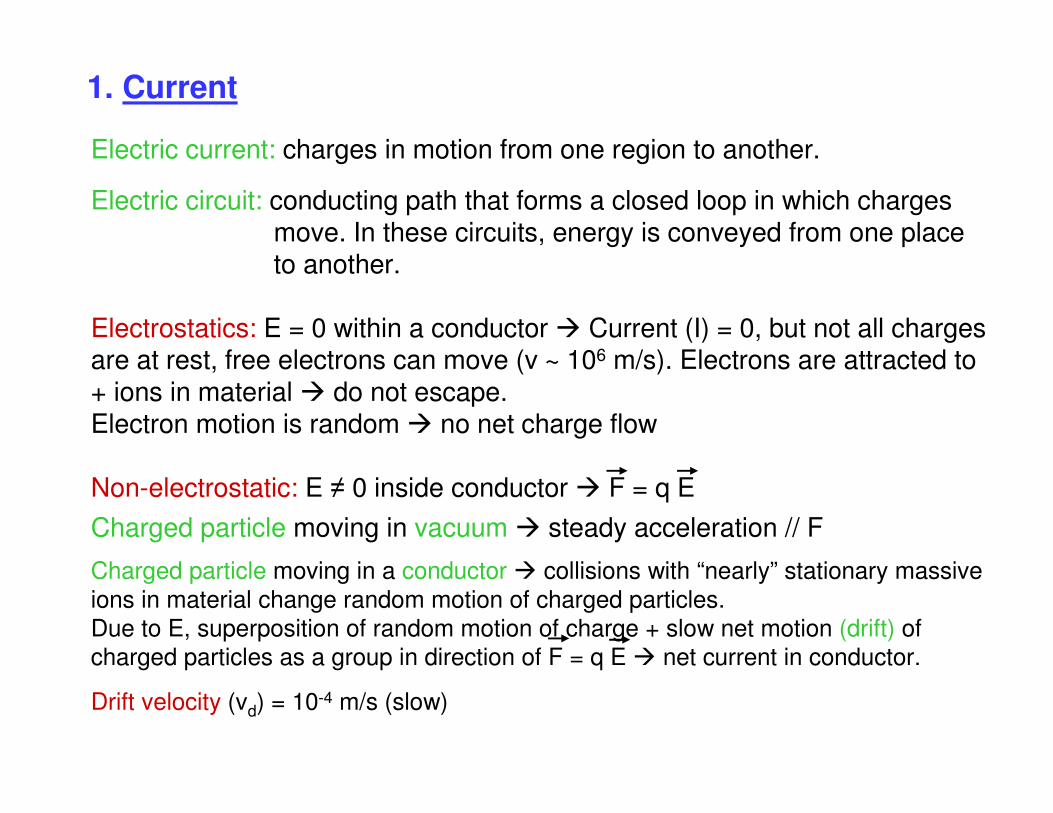
1. Current
Electric current: charges in motion from one region to another.
Electric circuit: conducting path that forms a closed loop in which charges move. In these circuits, energy is conveyed from one placeto another.
Electrostatics: E = 0 within a conductor Current (I) = 0, but not all chargesare at rest, free electrons can move (v ~ 106 m/s). Electrons are attracted to
+ ions in material do not escape. Electron motion is random no net charge flow
Non-electrostatic: E ≠ 0 inside conductor F = q E
Charged particle moving in vacuum steady acceleration // F
Charged particle moving in a conductor collisions with “nearly” stationary massive
ions in material change random motion of charged particles.
Due to E, superposition of random motion of charge + slow net motion (drift) of
charged particles as a group in direction of F = q E net current in conductor.
Drift velocity (vd) = 10-4 m/s (slow)
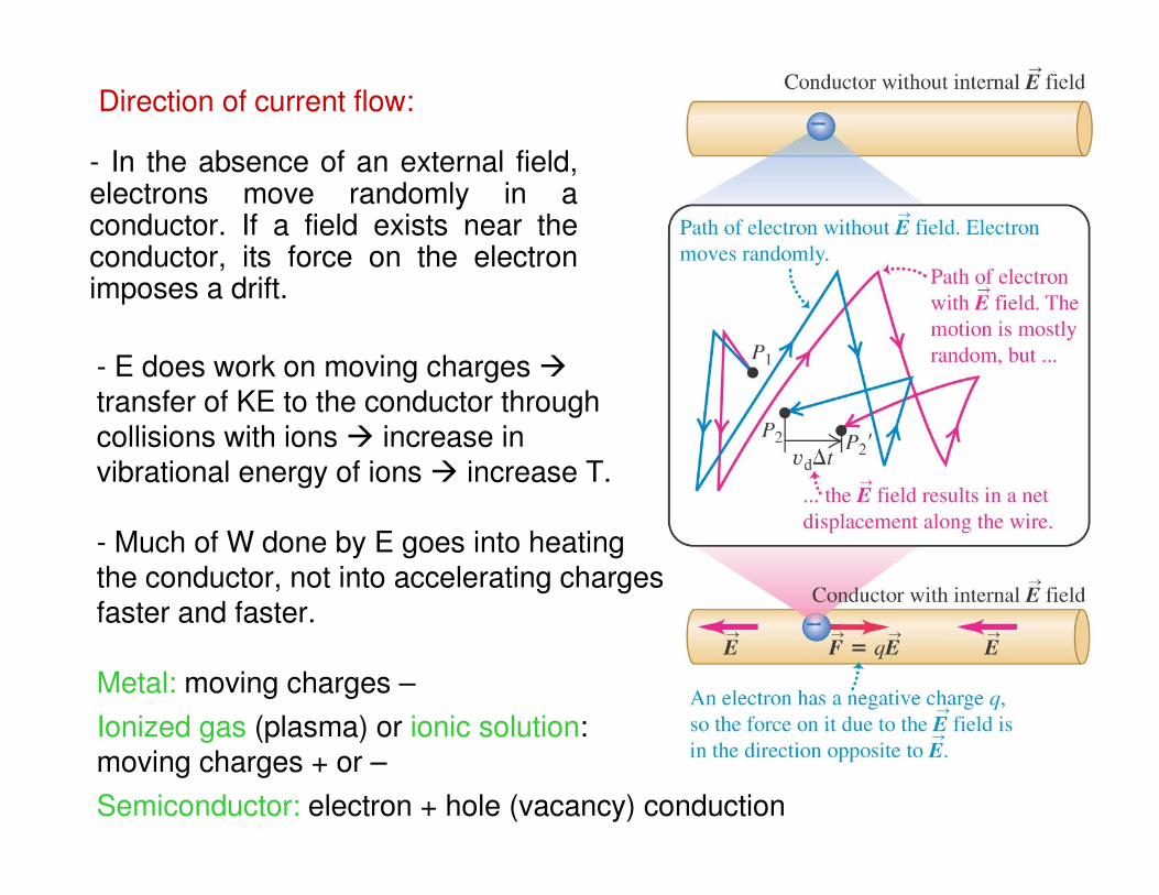
Direction of current flow:
- In the absence of an external field, electrons move randomly in a conductor. If a field exists near the conductor, its force on the electron imposes a drift.
- E does work on moving charges transfer of KE to the conductor throughcollisions with ions increase in vibrational energy of ions increase T.
- Much of W done by E goes into heating the conductor, not into accelerating chargesfaster and faster.
Metal: moving charges –
Ionized gas (plasma) or ionic solution: moving charges + or –
Semiconductor: electron + hole (vacancy) conduction
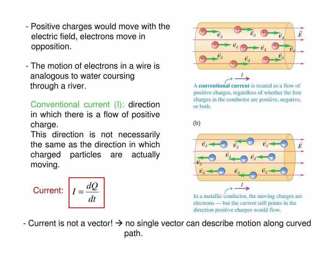
- Positive charges would move with the electric field, electrons move in opposition.
- The motion of electrons in a wire is analogous to water coursing through a river.
Current:dt
dQI =
Conventional current (I): direction in which there is a flow of positive charge.This direction is not necessarily the same as the direction in which charged particles are actually moving.
- Current is not a vector! no single vector can describe motion along curvedpath.
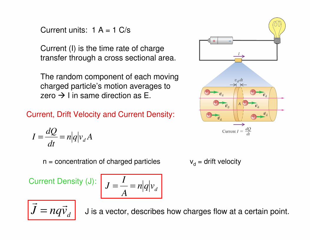
Current units: 1 A = 1 C/s
Current, Drift Velocity and Current Density:
Current (I) is the time rate of charge transfer through a cross sectional area.
The random component of each moving charged particle’s motion averages to zero I in same direction as E.
n = concentration of charged particles vd = drift velocity
Avqndt
dQI d==
dvnqJ
=
Current Density (J):dvqn
A
IJ ==
J is a vector, describes how charges flow at a certain point.
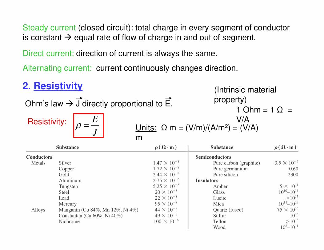
Steady current (closed circuit): total charge in every segment of conductor is constant equal rate of flow of charge in and out of segment.
Direct current: direction of current is always the same.
Alternating current: current continuously changes direction.
2. Resistivity
Ohm’s law J directly proportional to E.
Resistivity:
J
E=ρ Units: Ω m = (V/m)/(A/m2) = (V/A)
m
1 Ohm = 1 Ω = V/A
(Intrinsic material property)
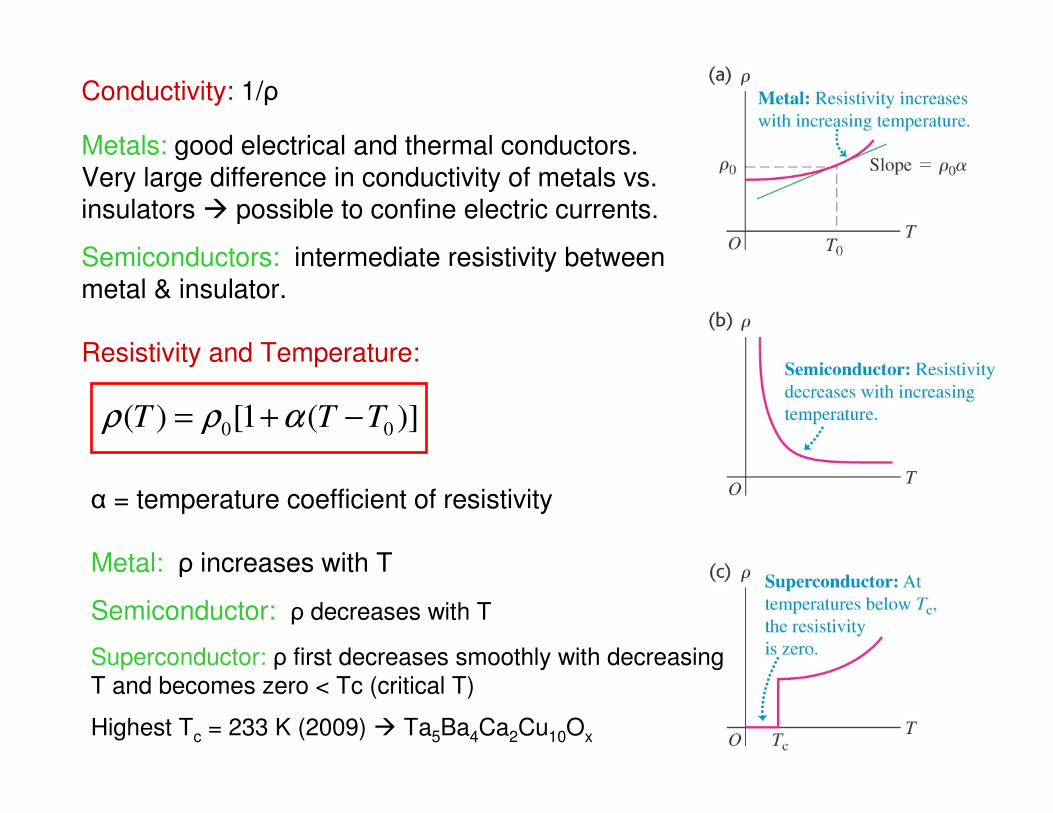
Conductivity: 1/ρ
Metals: good electrical and thermal conductors. Very large difference in conductivity of metals vs.insulators possible to confine electric currents.
Semiconductors: intermediate resistivity betweenmetal & insulator.
Resistivity and Temperature:
)](1[)(00
TTT −+= αρρ
α = temperature coefficient of resistivity
Metal: ρ increases with T
Semiconductor: ρ decreases with T
Superconductor: ρ first decreases smoothly with decreasing
T and becomes zero < Tc (critical T)
Highest Tc = 233 K (2009) Ta5Ba4Ca2Cu10Ox
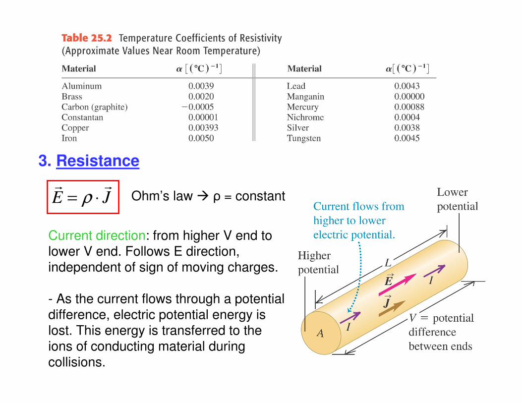
3. Resistance
JE
⋅= ρ Ohm’s law ρ = constant
Current direction: from higher V end to lower V end. Follows E direction, independent of sign of moving charges.
- As the current flows through a potential difference, electric potential energy is lost. This energy is transferred to the ions of conducting material during collisions.
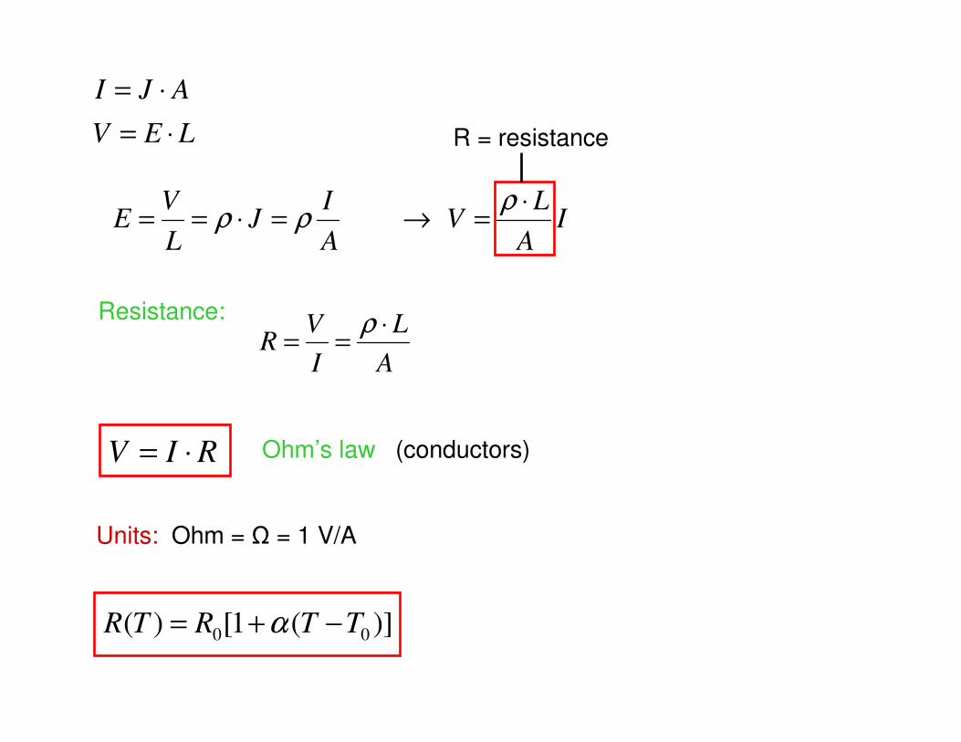
LEV
AJI
⋅=
⋅=
IA
LV
A
IJ
L
VE
⋅=→=⋅==
ρρρ
A
L
I
VR
⋅==
ρ
R = resistance
Resistance:
RIV ⋅= Ohm’s law (conductors)
Units: Ohm = Ω = 1 V/A
)](1[)(00
TTRTR −+= α
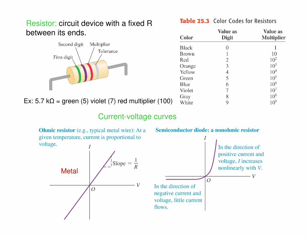
Resistor: circuit device with a fixed R between its ends.
Ex: 5.7 kΩ = green (5) violet (7) red multiplier (100)
Current-voltage curves
Metal
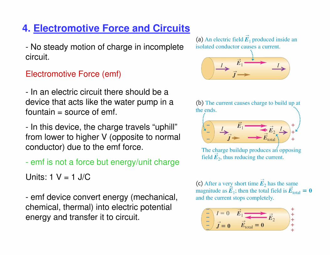
4. Electromotive Force and Circuits
- No steady motion of charge in incompletecircuit.
- In an electric circuit there should be a device that acts like the water pump in a fountain = source of emf.
- In this device, the charge travels “uphill”from lower to higher V (opposite to normal conductor) due to the emf force.
- emf is not a force but energy/unit charge
Units: 1 V = 1 J/C
- emf device convert energy (mechanical, chemical, thermal) into electric potential energy and transfer it to circuit.
Electromotive Force (emf)
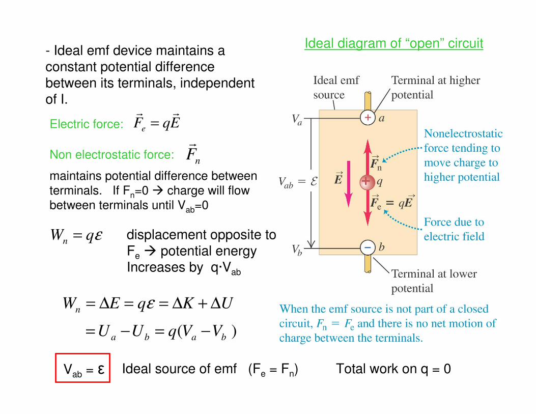
Ideal diagram of “open” circuit
εqWn =
nF
EqFe
=
- Ideal emf device maintains a constant potential difference between its terminals, independent of I.
Electric force:
Non electrostatic force:
maintains potential difference between
terminals. If Fn=0 charge will flow
between terminals until Vab=0
displacement opposite toFe potential energy Increases by q·Vab
)( baba
n
VVqUU
UKqEW
−=−=
∆+∆==∆= ε
Vab = ε Ideal source of emf (Fe = Fn) Total work on q = 0
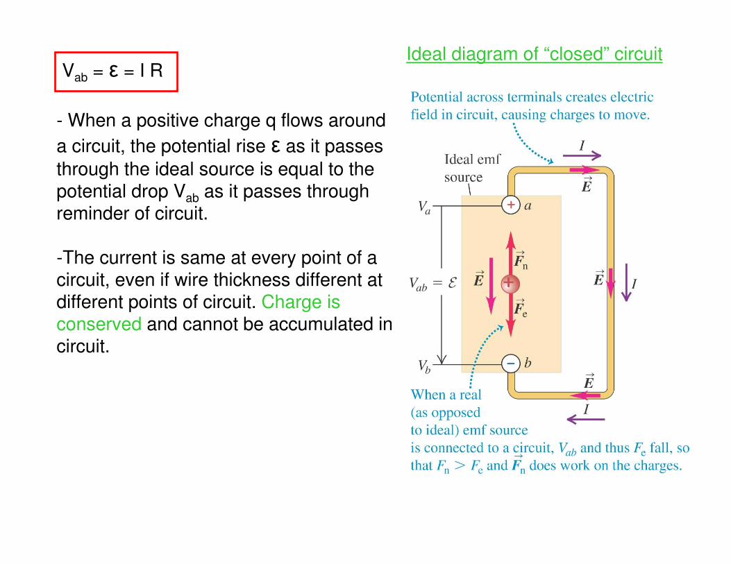
Ideal diagram of “closed” circuitVab = ε = I R
- When a positive charge q flows around
a circuit, the potential rise ε as it passes
through the ideal source is equal to the potential drop Vab as it passes through reminder of circuit.
-The current is same at every point of a circuit, even if wire thickness different at different points of circuit. Charge is conserved and cannot be accumulated incircuit.
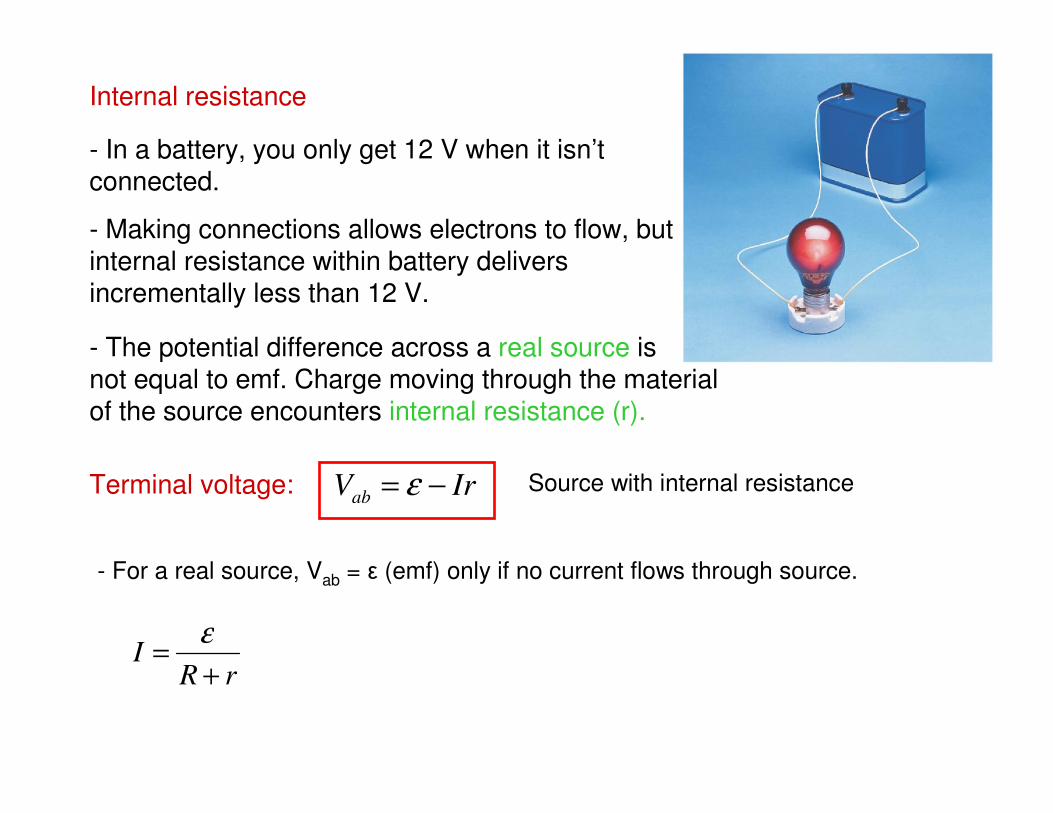
Internal resistance
- In a battery, you only get 12 V when it isn’t connected.
- Making connections allows electrons to flow, but internal resistance within battery delivers incrementally less than 12 V.
- The potential difference across a real source isnot equal to emf. Charge moving through the material of the source encounters internal resistance (r).
IrVab −= ε
rRI
+=
ε
Terminal voltage: Source with internal resistance
- For a real source, Vab = ε (emf) only if no current flows through source.
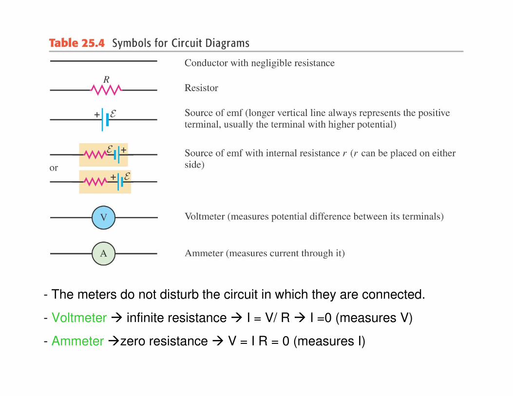
- The meters do not disturb the circuit in which they are connected.
- Voltmeter infinite resistance I = V/ R I =0 (measures V)
- Ammeter zero resistance V = I R = 0 (measures I)
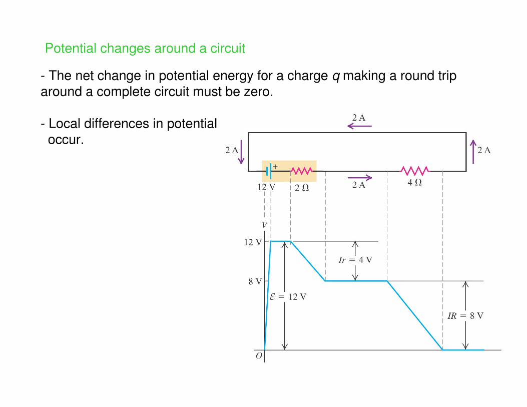
Potential changes around a circuit
- The net change in potential energy for a charge q making a round trip around a complete circuit must be zero.
- Local differences in potential occur.
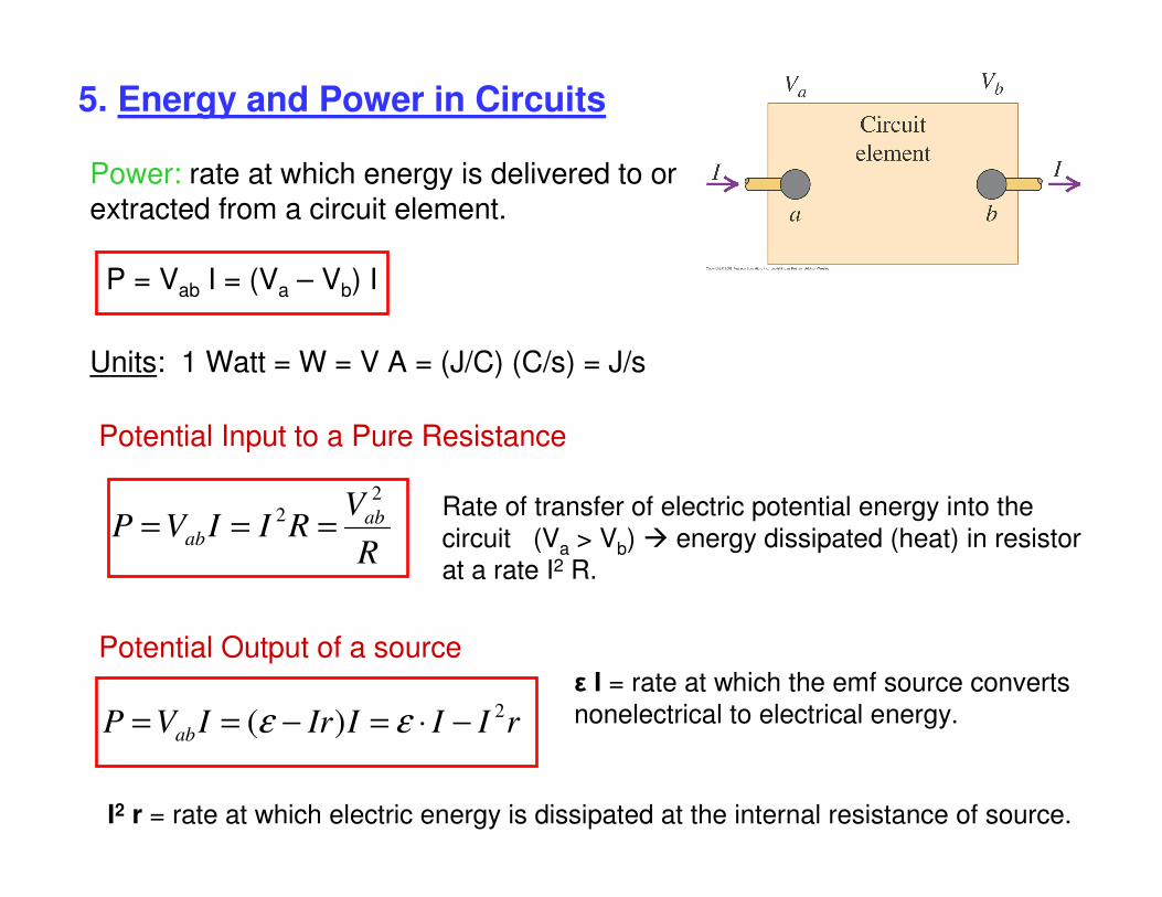
5. Energy and Power in Circuits
Power: rate at which energy is delivered to orextracted from a circuit element.
P = Vab I = (Va – Vb) I
Units: 1 Watt = W = V A = (J/C) (C/s) = J/s
Potential Input to a Pure Resistance
Rate of transfer of electric potential energy into the
circuit (Va > Vb) energy dissipated (heat) in resistor
at a rate I2 R.R
VRIIVP ab
ab
2
2 ===
Potential Output of a source
rIIIIrIVP ab
2)( −⋅=−== εε
ε I = rate at which the emf source converts
nonelectrical to electrical energy.
I2 r = rate at which electric energy is dissipated at the internal resistance of source.
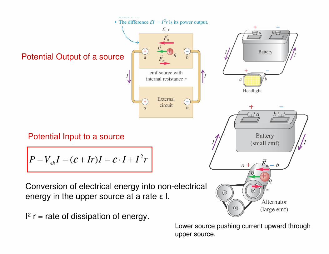
Potential Input to a source
Potential Output of a source
rIIIIrIVP ab
2)( +⋅=+== εε
Lower source pushing current upward through
upper source.
Conversion of electrical energy into non-electricalenergy in the upper source at a rate ε I.
I2 r = rate of dissipation of energy.
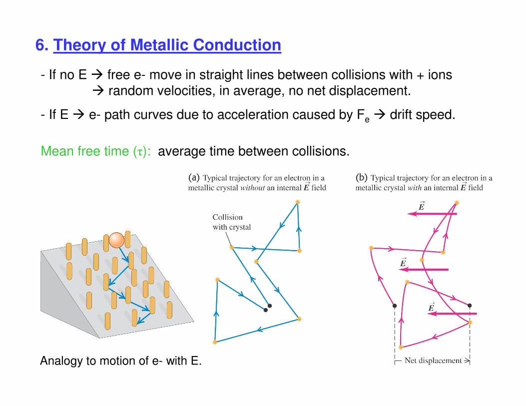
6. Theory of Metallic Conduction
- If no E free e- move in straight lines between collisions with + ions random velocities, in average, no net displacement.
- If E e- path curves due to acceleration caused by Fe drift speed.
Analogy to motion of e- with E.
Mean free time (τ): average time between collisions.
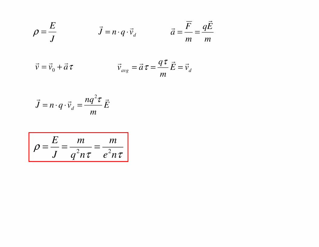
J
E=ρ dvqnJ
⋅⋅=m
Eq
m
Fa
==
τavv
+=0 davg vE
m
qav
===τ
τ
Em
nqvqnJ d
τ2=⋅⋅=
ττρ
ne
m
nq
m
J
E22
===