faraday s law - mitweb.mit.edu/8.02t/www/mitxmaterials/presentations/presentation_w10d1.pdf ·...
TRANSCRIPT

Faraday’s Law
W10D1
1

Announcements
PS 8 due Week 10 Tuesday at 9 pm in boxes outside 26-152 Week 10 Prepset due Week 10 Friday at 8:30 am Sunday Tutoring in 26-152 from 1-5 pm on April 14 Exam 2: Week 11 Thursday Evening 7:30-9:30 pm
2

Conflict Forms
3
Exam 2 Google Conflict Form for Friday April 19 https://docs.google.com/forms/d/e/1FAIpQLSe6-x4HAqRHZlC9sDt1sStfqtZwDpD_tRrOZ54IxoiiJvdorg/viewform?usp=sf_link Exam 2 Google Conflict Form for Students who are out of town April 18 and April 19 https://docs.google.com/forms/d/e/1FAIpQLSf1dT_SSrTXtzuD5G3giXjipHYh-R_u45POl5TJfbQwZ0TvaQ/viewform?usp=sf_link

Outline
Magnetic Flux Electromotive Force Lenz’s Law Faraday’s Law Induced Electric Fields Applications of Faraday’s Law
4

Michael Faraday
5
!E ⋅d!s
C"∫ = − d
dt!B ⋅d!A
S∫∫
Faraday’s Law

Demonstration: Faraday’s Law
Aluminum Sleeve Falling Past a Magnet
6

Ring Falling Through a Magnet
7

Magnet Falling Through Ring
8

Demonstration: Magnet falling through
copper pipe
http://techtv.mit.edu/videos/17898-lenz-s-law-with-copper-pipe
9

Demonstration: Magnet Falling
Through Plastic Tube, Aluminum Tube, and Copper Tube
http://tsgphysics.mit.edu/front/?page=demo.php&letnum=H%2016&show=0 10

Magnetic Flux Thru Wire Loop
ΦB =
B ⋅dA
S∫∫
B
A
(1) Uniform
Product of perpendicular component of magnetic field and area (2) Non-Uniform
ΦB = B⊥ A = B Ac o sθΦB =
B ⋅A
B
B
11

Review: Electromotive Force (emf) Electromotive force (emf) is defined to as the integral of a force per charge integrated around a closed path, at a fixed instant in time.
Emf has the same dimensions as electric potential rather than force, so the SI unit is the volt.
If the closed path is a circuit with resistance R then the electromotive force will cause a current to flow according to
ε = IR
ε = 1
q
!F ⋅d!s
closd path"∫
12

Electromotive Force (emf) in a current loop moving in a magnetic field
When a wire loop is moved with a velocity
through a magnetic field. There is a magnetic force per charge equal to
The line integral of the magnetic force around the loop at a fixed instant in time is then an example of an electromotive force (emf), called motional emf.
ε = 1
q
!Fmag ⋅d
!sclosd path"∫
13
!Fmag / q = !v ×
!B
!v

B B = 0
ij
kqw
O x
y
uFB v FP
Motional emf
Pull a loop with speed v through uniform magnetic field (shaded area). Magnetic force on moving charge is At one instant in time, electromotive force is (integrating clockwise)
ε = 1
q!Fmag ⋅d
!s"∫ = (vB j− uBi) ⋅dy jy=0
y=w
∫ = vBw14
!Fmag / q = (vi + uj)× B(−k)= vB j− uBi

Changing Magnetic Flux and Motional emf
When the loop moves a distance Δs = vΔt, magnetic flux through loop is decreasing by
− ΔΦB
Δt= BwΔs
Δt= BwvΔt
Δt= vBw
B
B = 0
v
ij
kw
O x
y s
15
ΔΦB = −BwΔs
The negative of the time derivative of the magnetic flux:

Electromotive Force and Changing Magnetic Flux
Electromotive force is equal to the negative time rate of change of magnetic flux through an open surface
16
ε = − ddt
!B ⋅ nda
opensurface
∫∫
Iind R = − ddt
!B ⋅ nda
opensurface
∫∫
If there is a time rate of change of magnetic flux through a closed conducting path of resistance R then there is an induced current in the con ducting path according to

Electromotive Force (emf) and work Because the electromotive force is defined as an integral at one instant in time it is not magnetic work per charge. Recall that magnetic fields do no work! The work done per charge by the pulling force on the loop is equal to the electromotive force.
B B = 0
ij
kw
O x
y
FPv
17
1q!F P ⋅d!s
i
f
∫ = vBw = ε

18
CQ: Moving Loop in Uniform Field II
In the figure to the right, the shaded region represents non-zero magnetic field directed out of the plane of the figure. A rectangular wire loop is pulled to the left with speed v. At the instant shown in the figure, there is 1. no current in the loop. 2. a current in the loop.
B B
B = 0v
18

Lenz’s Law
Induced EMF is in direction that opposes the change in flux that caused it. Induced current, torque, or force is always directed to oppose the change that caused it
ε = −
dΦB
dt
19
vS N Iind

For a Closed Conducting Path
Induced current is the source of induced magnetic flux that opposes the change in external magnetic flux.
Iind R = −
dΦB
dt
20
vS N Iind
Iind

Direction of Induced Current
Φring > 0
dΦB
dt< 0
ε = −dΦB
dt> 0
⇒ Iind counterclockwise
Choose upwards unit normal for the magnetic flux surface integral. There is a current I in the ring that is decreasing in time, so the magnetic field inside the ring is pointing upwards and decreasing in time.
!21

22
CQ: Moving Loop in Uniform Field Lenz’s Law
In the figure to the right, the shaded region represents non-zero magnetic field directed out of the plane of the figure. A rectangular wire loop is pulled upward with speed v. At the instant shown in the figure, there is 1. a counterclockwise current in
the loop. 2. a clockwise current in the loop. 3. There is no current in the loop. 22
B B
B = 0
v

Demo: Electromagnetic
Induction Move magnet
with current loop fixed
Moving magnet through fixed current loop
http://tsgphysics.mit.edu/front/?page=demo.php&letnum=H%203&show=0 23

Faraday’s Law Applet: Move Magnet Keep Loop Fixed
http://public.mitx.mit.edu/gwt-teal/FaradaysLaw2.html
24

Simulation: Faraday’s Law Applet:
http://public.mitx.mit.edu/gwt-teal/FaradaysLaw2.html 25
1. Open the simulation 2. Move magnet and compare induced current and change of
total magnetic flux 3. Move ring and compare induced current and change of total
magnetic flux 4. Click motion on and compare induced current and change
of total magnetic flux 5. While motion on, generate field visualization by clicking on
Magnetic Field Iron Filings 6. Change dipole and resistance and observe effect either
when moving magnet or ring, or when motion on Discussion Question with Group: What is the difference between external flux and total flux

What is the emf? Conducting loop, with resistance R, is at rest, and magnet is moving as shown in figure, resulting in a changing magnetic flux through the loop and an induced current in the loop. What is the source of the emf?
ε = Iind R
26
vS N Iind

An induced electric field appears in the current loop resulting in an electric force on the charges in the conductor. Hence there is an electromotive force that is equal to the change in magnetic flux
The induced current is then equal to
Induced Electric Field and Electromotive Force (emf)
ε =!E ⋅d!s
loop"∫ = − d
dt
!B ⋅d!A
open surfacewith loop asboundary
∫∫
ε = IR27

Faraday’s Law of Induction If C is a stationary closed curve and S is a surface spanning C then
The changing magnetic flux through S induces a non-electrostatic electric field whose line integral around C is non-zero
E ⋅ds
C∫ = − d
dtB ⋅dA
S∫∫
ε = −
dΦB
dt28

Ways to Induce Changing Magnetic Flux
Quantities which can vary with time: • Area A enclosed by the loop with non-zero B • Magnitude of B • Loop moving through non-uniform B • Angle between B and normal vector to loop
ε = − d
dt
!B ⋅ n da
open surface∫∫
29

CQ: Magnetic Field Changing in Time Lenz’s Law
The magnetic field through a wire loop is pointed upwards and increasing with time. The induced current in the wire loop is 1. clockwise as seen from the
top. 2. counterclockwise as seen
from the top. 3. zero.
30

Group Problem: Changing Magnetic Flux
Conducting rod pulled along two conducting rails in a uniform magnetic field of magnitude B at constant speed v. Assume the resistance has value R.
a) Calculate the magnitude of the derivative of the magnetic flux with respect to time.
b) What is the magnitude of the induced
current?
31

32
CQ: Lenz’s Law Moving Loop A circuit in the form of a rectangular piece of wire is pulled away from a long wire carrying current I in the direction shown in the sketch. The induced current in the rectangular circuit is 1. Clockwise 2. Counterclockwise 3. Neither, the current is zero
32

CQ: Solenoid At time t: the figure on the right shows a side view of a section of a very long solenoid with radius R carrying current I with magnetic field pointing up. The figure below right shows a top view of the electric field inside the solenoid at a radius r and the direction of the magnetic field. In the solenoid, the current is 1. increasing in time. 2. constant. 3. decreasing in time. 4. cannot tell without more information.
!
!33

Sign Conventions: Right Hand Rule
By the right hand rule (RHR) clockwise integration direction for line integral of electric field (emf) requires that unit normal points into plane of figure for magnetic flux surface integral
Magnetic flux positive into page, negative out of page
:
!E ⋅d!s
closed path"∫ = − d
dt
!B ⋅d!A
open surface∫∫
34
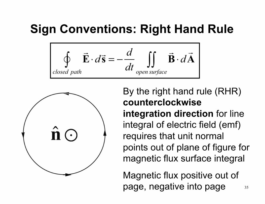
Sign Conventions: Right Hand Rule
By the right hand rule (RHR) counterclockwise integration direction for line integral of electric field (emf) requires that unit normal points out of plane of figure for magnetic flux surface integral
Magnetic flux positive out of page, negative into page
E ⋅ds
closed path∫ = − d
dt
B ⋅dA
open surface∫∫
35

Group Problem: Induced Electric Field Consider a uniform magnetic field which points into the page and is confined to a circular region with radius R. Suppose the magnitude increases with time, i.e. dB/dt > 0. Find the magnitude and direction of the electric field in the regions (i) r < R, and (ii) r > R. (iii) Plot the magnitude of the electric field as a function r.
!E ⋅d!s
C"∫ = − d
dt!B ⋅d!A
S∫∫
36