chapter 9 cross sections & labeling -...
TRANSCRIPT
4/12/16 Missouri Department of Transportation
Chapter 9
Cross Sections &
Labeling 9.1 Objectives .............................................................................................................................. 9-1
9.2 Cross Sections Overview ....................................................................................................... 9-1 9.3 Create Cross Sections ............................................................................................................ 9-2
9.4 Create Cross Sections Dialog ............................................................................................ 9-4 9.5 Annotate Cross Sections .................................................................................................. 9-13 9.6 Cross Section Viewer ....................................................................................................... 9-19
9.7 Group Exercise: Cutting Road1 Cross Sections and Annotation......................................... 9-20 9.8 Individual Exercise 5-1: Cutting Route 63 Cross Sections and Annotation ........................ 9-26


GEOPAK Road 1 Chapter 9 – Cross Sections & Labeling
4/12/16 Missouri Department of Transportation 9-1
9.1 Objectives
Create cross sections along a previously designed corridor.
Annotate proposed cross sections.
9.2 Cross Sections Overview
Corridor Modeling Cross Section commands extract, display, annotate, and update cross sections.
These commands also allow you to export data from cross sections to a surface.
A cross section is a two-dimensional window of graphics representing a planar section of a three-
dimensional (3-D) model. Typically, the 3-D objects displayed in cross section are terrain models
and objects such as the existing terrain or a proposed road. The graphics showing a terrain model
in a cross section is a cross section surface.
Cross sections are extracted across a horizontal alignment or some other linear feature. (Cross
sections can be extracted at a skewed angle, but they are typically perpendicular to the
alignment). The width of the cross section window is defined relative to the linear feature. For
example, you might want your cross sections to span the range from 50 feet left of the alignment
to 50 feet right of the alignment. The height of the cross section represents a range of elevation,
for example from 380 to 400 feet.
When you create one or more cross sections, you choose which surfaces to display. Each cross
section displays the selected surfaces as they pass through the window. Each surface is
represented in the cross section by a data line known as a cross section surface.
Cross sections serve several purposes during a project. They allow you to examine your model in
detail. For example, you can verify that a ditch you have designed is being placed properly or that
your roadway side slope is at the correct grade. You can annotate the points and lines in cross
sections by slope as well as offset and elevation.
Other important uses for cross sections are computing cut and fill volumes.

Chapter 9 – Cross Sections & Labeling GEOPAK Road 1
9-2 Missouri Department of Transportation 4/12/16
9.3 Create Cross Sections
Extracts multiple cross sections and draws them in
a matrix pattern. These sections are subsequently
used for cross section sheets and earthwork calculations.
Only the surfaces that you select when you initiate the
command are displayed in the cross sections.
Typically, you use this command to extract cross sections
along the active horizontal alignment; however, this
command can generate cross sections along graphic
elements.
Features are projected based on Feature Definition Settings.
Symbology Cross Section Tools
The Create Cross Sections command determines the surface symbology from a terrain model or
an object. This gives predictable symbology results since the terrain model is driving the
symbology.
The cross section creation application requires the selection of an alignment in which the user
desires to cut cross sections along. In any given design, the user has the option to create all of
their planimetrics and alignments in a 2D model or a 3D model. If the user decides to work in
2D, then a 3D model will be automatically created in the background for the user and maintained
by the product as design changes are made. In this scenario, the user should reference in the 2D
model because that is where the alignment is stored.
A 2D model is used for design as suggested as a “Best Practice”. When cross sections are created,
the application “slices” the 3D model to determine the components to display on the cross section.
It is required to reference in the proposed alignment. If that alignment is in the 2D model, then
simply referencing that model is not sufficient. In our 2D design model, we have referenced in
automatically the 3D model once vertical geometry is created. For the Create Cross Section
application to have access to this 3D model, it must be referenced to the cross section drawing as
well. The most efficient way to accomplish this and make sure no references are missed.
Finally, once the design model is attached, the user should at this time set each level display to the
desired preference. The create cross section application works on a WYSIWYG premises. For
example: suppose in your design, a guardrail was placed in your 3D model. However, it was not
desired to see this guardrail on your proposed cross sections. By simply turning this level off and
saving your settings, when cross sections are created, this level will not be displayed. The level
settings need to be made at the 3D model level. Once each level setting is verified, make sure to
Save Settings in the DGN file for those preferences to be remembered.
The Create Cross Section application acts as a “cookie cutter” based on a WYSIWYG
functionality. The Create Cross Section application slices through the 3D design model at
specified even intervals or customized cross section locations. It is important that a template drop
location exists in the design corridor at each station location where proposed cross sections are
intended to be generated. We do this to avoid interpolation between template drop locations. For

GEOPAK Road 1 Chapter 9 – Cross Sections & Labeling
4/12/16 Missouri Department of Transportation 9-3
example, if a design called for a template drop every 20 feet but the user wanted to create cross
sections at a 10 foot interval, every other section would be interpolated and risks a chance of the
proposed finished grade and existing ground not precisely connecting. In the MoDOT workspace,
several design stages exist that may be assigned to any Corridor, which will directly affect the
template drop interval multiplier.
Corridor Design Stages directly affect the interval of template drops. When creating a Corridor,
one of the prompts will ask the user for the Template Drop Interval. The user should always key
in the desired final interval. Then, based on the selected Corridor Design Stage selected, the
template drop interval will be increased by the design stage template drop interval multiplier. For
example, the template drop interval multiplier for the Preliminary Design Stage is 40. So if a user
puts in a final template drop interval of 10 and then selects the Preliminary Design stage, the
corridor design will contain a template drop every 400 feet or 10 x 40 = 400. This concept has
been adopted to allow for very fast model processing in the Preliminary Design stage.
Consequently, the multiplier for the Design Stage is set to 2, and the multiplier for the Final
Design Stage is set to 1. These settings are stored in a DGNLib for Project Settings in the
included MoDOT_workspace. Each customer will likely want to review and modify these
settings based on their individual workflows for in-house design work.
When cross sections are created, the application automatically creates a DGN Drawing Model and
writes the cross sections to that Model. The user is granted the opportunity to name the Drawing
Model before it gets created. By default, the name will correspond to the name of the alignment
the cross sections are being developed along. It is acceptable practice to cut multiple sets of cross
sections in the same DGN file. Each time cross sections are created, they will be drawn to a new
and differently named DGN Drawing Model.
Finally, the created proposed cross sections are not presently “dynamic”. Thus, if the design
model changes, the user would be required to re-create the cross sections. GEOPAK SS4 does
contain a Dynamic Cross Section viewer, which does dynamically update as the model undergoes
continued design updates. Before re-creating the proposed cross sections, the user may choose to
delete the previously created DGN Drawing Model. If the user intends to create an output of cross
sections, such as, creating cross section sheets, legacy tools must be used.
GEOPAK>ROAD>Cross Sections.
Cross Section Workflow
1. Create a new cross section DGN file.
2. Reference in the proposed design to the cross section DGN file.
3. Setting the appropriate levels on or off for cross section display preferences.
4. Create the proposed cross sections from the 3D design model.
Each DGN file contains one or more models, each of which has its own set of eight views.
You can create a model as a 2D or 3D Design type, as a 2D Drawing type or as a 2D or 3D
Sheet type. Sheet models let you attach references to create a set of working drawings for the
model file. Icons at the top of the Models dialog give you access to its various functions.

Chapter 9 – Cross Sections & Labeling GEOPAK Road 1
9-4 Missouri Department of Transportation 4/12/16
5. Navigate the proposed cross sections.
6. Annotate the proposed cross sections.
7. Compute end-area volumes of the proposed cross sections.
9.4 Create Cross Sections Dialog
General Leaf
1. The Preference dialog must be
opened to be able to choose a
predefined setting.
3. MoDOT utilizes 3 different
scaled sheet labels, 1 Geopak
cross section cell and 1
Geopak cross section cell with
a grid and axis.
When you choose a predefined
setting it will show you which
setting has been selected in the
Preferences dialog at the
bottom.
2. Select a preference then
select the Load button to load
the preference.

GEOPAK Road 1 Chapter 9 – Cross Sections & Labeling
4/12/16 Missouri Department of Transportation 9-5
Spacing Leaf - Use this dialog to define the settings for stacked or sheet modes.
Distance between sections
Stationing
Annotation Scale at creation, impacts text sizes,
and offsets plus multiplies the tick lengths.
This defines the number of cross sections that display
in each column of the matrix.
Geopak cell
offsets
These options define the
horizontal and vertical
offset from one cross
section to the next.
Window Clearance adds
additional space at the top
and bottom of each
extracted cross section
(inside each cross
section). The predefined
preference already has the
default set.
Direction specifies the direction to
display stacked cross sections.
Chapter 9 – Cross Sections & Labeling GEOPAK Road 1
9-6 Missouri Department of Transportation 4/12/16
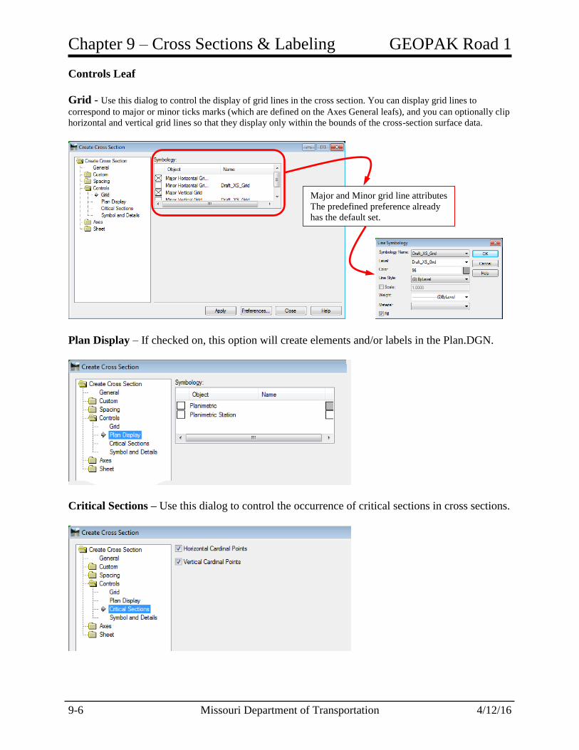
Controls Leaf
Grid - Use this dialog to control the display of grid lines in the cross section. You can display grid lines to
correspond to major or minor ticks marks (which are defined on the Axes General leafs), and you can optionally clip
horizontal and vertical grid lines so that they display only within the bounds of the cross-section surface data.
Plan Display – If checked on, this option will create elements and/or labels in the Plan.DGN.
Critical Sections – Use this dialog to control the occurrence of critical sections in cross sections.
Major and Minor grid line attributes
The predefined preference already
has the default set.

GEOPAK Road 1 Chapter 9 – Cross Sections & Labeling
4/12/16 Missouri Department of Transportation 9-7
Horizontal Cardinal Points - extracts cross sections at the cardinal points of the horizontal
alignment specified on the General leaf (PC, PT, and so forth).
Vertical Cardinal Points - extracts cross sections at the cardinal points of the active vertical
alignment corresponding to the horizontal alignment specified on the General leaf.
Symbols and Details – This option is not used within the MoDOT default set up.
Axes Leaf - General
Use this dialog to control which parts of each cross section axis to display and in what format.
For each axis, you can display a number of features, including the axis line itself, a title text
string and title box (next to the axis), annotation text for the data associated with the axis, and the
major and minor ticks that are displayed along the axis.
Major Ticks
Length - defines the length of
major tick marks. If the length
is zero, the tick length will be
one half of the label text height.
Position - places major tick
marks inside, outside, or on
both sides of each axis.
Spacing - specifies the distance
between major ticks along the
axis. For top and bottom cross
section axes, a major tick is
always placed at the axis
endpoints, regardless of the
stationing values at those points,
while for top and bottom cross
section axes, a major tick is
always placed first at the
centerline point. This parameter
determines how to place all
subsequent major tick marks
along the axis.
Minor Ticks
Length - defines the length of minor tick marks. If the length is zero, the tick
length will be one half of the label text height.
Position - places minor tick marks inside, outside, or on both sides of the
axis.
Minors/Major - specifies the number of minor tick marks to display between
neighboring major tick marks.

Chapter 9 – Cross Sections & Labeling GEOPAK Road 1
9-8 Missouri Department of Transportation 4/12/16
Axes Leaf – Symbology
Use this dialog to specify the symbology settings for the Axes. These settings have been set up to
MoDOT’s standards once the preference has been selected.
Elevation Label - defines a text string for each axis other than the bottom axis. The stationing value serves as
the title for the bottom axis.
Prefix - specifies a text string to place at the beginning of the axis annotation text.
Suffix - specifies a text string to append to the axis annotation text.
Precision - specifies the number of digits to follow the decimal point in the axis annotation text.
Title Text - specifies text for individual axis.
Mirror Left to Right - displays the identical
settings on the Right axis.
This option is only available if the label uses a text
style.
This option is not available if the label uses a text
style.
Double clicking the object brings up the
Text Symbology dialog.
Offsets of Horizontal and Vertical control
where the text is located on the sheets.

GEOPAK Road 1 Chapter 9 – Cross Sections & Labeling
4/12/16 Missouri Department of Transportation 9-9
Sheet Leaf
Border
Layout
MoDOT’s border file located in
ProjectWise is attached with using the
“read only” option checked on.
pw:\\GHPWISE10.dot.missouri:MoDOT\Documents\CADD_Standards\Borders\MoDOT_DE_2008.dgn
Sheets per Column -
defines the number of
sheets per column for
stacking sheets. If 1 is
selected, sheets are
placed horizontally and
if a number greater than
the number of sheets
produced is selected for
sheets per column,
sheets are placed
vertically. This gives
you the ability to create
sheets in a grid display
instead of a long row or
column for plotting.
Scale - defines the size
exaggeration for the cross section.
Horizontal - defines the horizontal offset
from one drawing sheet outline to the
next.
Vertical - defines the vertical offset from
one drawing sheet outline to the next.
Margins
Left - defines the margin between the left border
and the cross sections.
Right - defines the margin between the right border
and the cross sections.
Top - defines the margin between the top border
and the cross sections.
Bottom - defines the margin between the bottom
border and the cross sections.

Chapter 9 – Cross Sections & Labeling GEOPAK Road 1
9-10 Missouri Department of Transportation 4/12/16
Range - Use this dialog to specify the settings for displaying station range annotation on each
sheet of cross sections.
Annotation - Use this dialog to define settings for title block annotation that is automatically
generated on cross section sheets. You can also define unique fields for annotation, such as
project name, and so on. This feature is available only when borders are attached as reference
files, and the tags are in the referenced border
Horizontal - specifies the
horizontal offset from the left of
the sheet for the sheet annotation.
Vertical - specifies the vertical
offset from the bottom of the sheet
for the sheet annotation.
Precision - specifies the number
of digits to the right of the decimal
point in the annotation text.
Format - specifies the station
format of the annotation text.

GEOPAK Road 1 Chapter 9 – Cross Sections & Labeling
4/12/16 Missouri Department of Transportation 9-11
The Tag values will need to be filled out the title block information.
Select a Tag Name and enter a value then select the “Update” button to apply the changes to the
tool settings.
**Note – If a field is left blank then it will not place any text where the Tag location was
defined.
The last 3 Tags will be predefined with the value needed to compute the sheet number and total
sheets along with the verbiage “SHEET OF.”

Chapter 9 – Cross Sections & Labeling GEOPAK Road 1
9-12 Missouri Department of Transportation 4/12/16
After the Tag values are completed the user can save a DAT file which saves the dialog
information so that the values can be easily recalled and used again.
The attached DAT file will be the default MoDOT.DAT file that resides on the
T:\MoDOT_Workspace\Modeling\Cross Sections and cannot be overwritten so you will need to
save a copy to your Job > Data folder.
Once the file is saved your data folder the tool will revert back to that location when opening the
tool the next time.
The pick button allows the user to load the MoDOT default DAT file by navigating to the
T:\MoDOT_Workspace\Modeling\Cross Sections folder and selecting the MoDOT.DAT file.
Once the cross sections have been defined, the information has been defined in the dialog and the
DAT file saved to the data folder the tool is ready to use.
Click on the Apply button to create the cross section model. The border will be referenced into
the model with instances created for each sheet that is created.

GEOPAK Road 1 Chapter 9 – Cross Sections & Labeling
4/12/16 Missouri Department of Transportation 9-13
The title block information will be filled out according to your settings and the informational
block will be created in the lower right, vertically with the defined settings that were defined in
the dialog.
**Note – The Make PDF Request can only handle 50 borders at one time so it is recommended
that you run all the cross sections in one model and then save as a copy (some may have 3 files
for cross sections) from the original.
Open the model containing the cross sections and remove the extra cross sections leaving the
cross sections needed for the Make PDF Request tool.
9.5 Annotate Cross Sections
Annotate Cross Sections places text describing the characteristics of cross sections that were
previously placed in the drawing file. These characteristics can include slope, width, elevation,
and offsets. The cross sections may have been placed with any of the cross-section extraction and
display options. Annotation allows you to know the characteristics of your design as you examine
cross sections.
Annotation for features obeys the design file annotation scale factor.
Which Elements Are Annotated?
The following controls what annotation appears in the cross section:
The Points, Features, and Segments leafs are used as master switches to turn on or off annotation
for points, segments, or features. For example, if Include Points is not checked, no point
annotation appears in cross sections. If Include Points is checked, points will be annotated.
The parameters on the Points, Features, Segments, and Frame leafs restrict which elements are
annotated.
The Annotate Cross Section command can annotate multiple surfaces in a single pass. On the
General dialog is a list view, which lists each surface in the cross section set and a preference.
The preference listed is either the active preference for the command or the preference defined in
Surface Properties for that surface, depending on style lock. This list view allows you to select
multiple surfaces to annotate.
The Annotate Cross Section application has the ability to label any particular cross section model
present in the active DGN file including models that are not active. In addition, we have the

Chapter 9 – Cross Sections & Labeling GEOPAK Road 1
9-14 Missouri Department of Transportation 4/12/16
ability to label any surface found within all models of our DGN file. The annotation application
is highly versatile to meet many different types of labeling needs. For example, the cross section
annotation application can label the individual objects along the cross section, along a bottom
axis, or in a frame mode. It is possible to label points along a surface, crossing linear features,
and component segments like the slopes of a proposed pavement for example. The supported
combinations are endless regarding all that can be labeled along a cross section.
Preferences are stored in the MoDOT workspace in a XIN file. Several preferences are provided
in the MoDOT workspace. The scales of 5, 10 and 20 support the cross section settings in the
MoDOT create cross section tool.
Choose the Model of the
Cross Section to annotate. Choose Surface to
be annotated.
Object - Places annotation text along the
graphics in the cross sections
Axis - Places annotation text along the
bottom axis of the cross section. This
option places text for points and features
only, not segments.
Frame - Places annotation text in rows
with frames around them. The size and
orientation of the frames are defined using
the Frame leaf dialog boxes.

GEOPAK Road 1 Chapter 9 – Cross Sections & Labeling
4/12/16 Missouri Department of Transportation 9-15
Points – Used to label points on cross sections.
Include Points - If checked,
includes points when
annotating cross sections. The last column
in the grid is the
means of access
to the symbology
dialog.
Offset Tolerance - if checked, will not annotate points within the
defined tolerance. This applies to points coming from the surface line
or from the ASCII file.
Object - displays object attributes in rows. The first column has check
boxes indicating which attributes are to be included in the annotation.
Leader - leader line for the annotation to follow.
Center - annotation of the centerline (zero offset) of the cross section.
Offset - annotation of the offset of any point in the cross section.
Elevation - annotation of the elevation of any point in the cross section.
Station - the station of the feature relative to the alignment.
Skew Offset - annotation of the offset of each point in the cross section.
The offset is measured along the cross section (not by normal projection).
Position - controls the position of
the annotation text. A value of zero
does not affect the text position. A
value of 1 moves the text so that it
displays one line above its original
position. A value of 2 moves the text
two lines above its original position,
and so forth. Negative values move
the text in the opposite direction.
Drop Station Equation Name - if checked,
drops the station equation name. If an equation
name exists at the station, it is not formatted as
part of the station. For example, station "a10+00"
is formatted as "10+00.00" when this option is
toggled on. When this option is toggled off,
station "a10+00" is formatted as "a10+00.00".
Leader Length - specifies the
length of the leader line from the
annotation text to the point being
annotated. If you key in zero, the
line is sized automatically according
to the length of the annotation text.
Chapter 9 – Cross Sections & Labeling GEOPAK Road 1
9-16 Missouri Department of Transportation 4/12/16
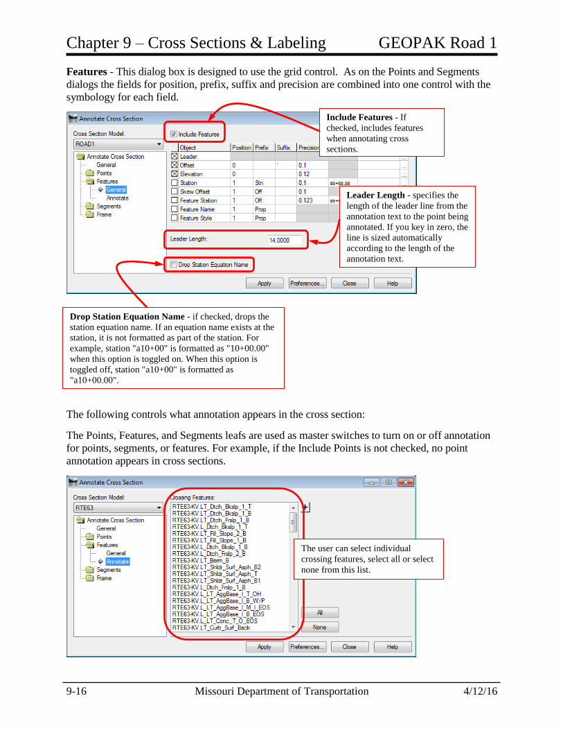
Features - This dialog box is designed to use the grid control. As on the Points and Segments
dialogs the fields for position, prefix, suffix and precision are combined into one control with the
symbology for each field.
The following controls what annotation appears in the cross section:
The Points, Features, and Segments leafs are used as master switches to turn on or off annotation
for points, segments, or features. For example, if the Include Points is not checked, no point
annotation appears in cross sections.
Include Features - If
checked, includes features
when annotating cross
sections.
Leader Length - specifies the
length of the leader line from the
annotation text to the point being
annotated. If you key in zero, the
line is sized automatically
according to the length of the
annotation text.
Drop Station Equation Name - if checked, drops the
station equation name. If an equation name exists at the
station, it is not formatted as part of the station. For
example, station "a10+00" is formatted as "10+00.00"
when this option is toggled on. When this option is
toggled off, station "a10+00" is formatted as
"a10+00.00".
The user can select individual
crossing features, select all or select
none from this list.
GEOPAK Road 1 Chapter 9 – Cross Sections & Labeling
4/12/16 Missouri Department of Transportation 9-17
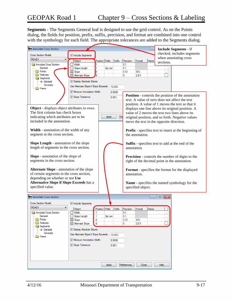
Segments - The Segments General leaf is designed to use the grid control. As on the Points
dialog, the fields for position, prefix, suffix, precision, and format are combined into one control
with the symbology for each field. The appropriate tolerances are added to the Segments dialog.
Include Segments - If
checked, includes segments
when annotating cross
sections.
Object - displays object attributes in rows.
The first column has check boxes
indicating which attributes are to be
included in the annotation.
Width - annotation of the width of any
segment in the cross section.
Slope Length - annotation of the slope
length of segments in the cross section.
Slope - annotation of the slope of
segments in the cross section.
Alternate Slope - annotation of the slope
of certain segments in the cross section,
depending on whether or not Use
Alternative Slope if Slope Exceeds has a
specified value.
Position - controls the position of the annotation
text. A value of zero does not affect the text
position. A value of 1 moves the text so that it
displays one line above its original position. A
value of 2 moves the text two lines above its
original position, and so forth. Negative values
move the text in the opposite direction.
Prefix - specifies text to insert at the beginning of
the annotation.
Suffix - specifies text to add at the end of the
annotation.
Precision - controls the number of digits to the
right of the decimal point in the annotation.
Format - specifies the format for the displayed
annotation.
Name - specifies the named symbology for the
specified object.
Chapter 9 – Cross Sections & Labeling GEOPAK Road 1
9-18 Missouri Department of Transportation 4/12/16
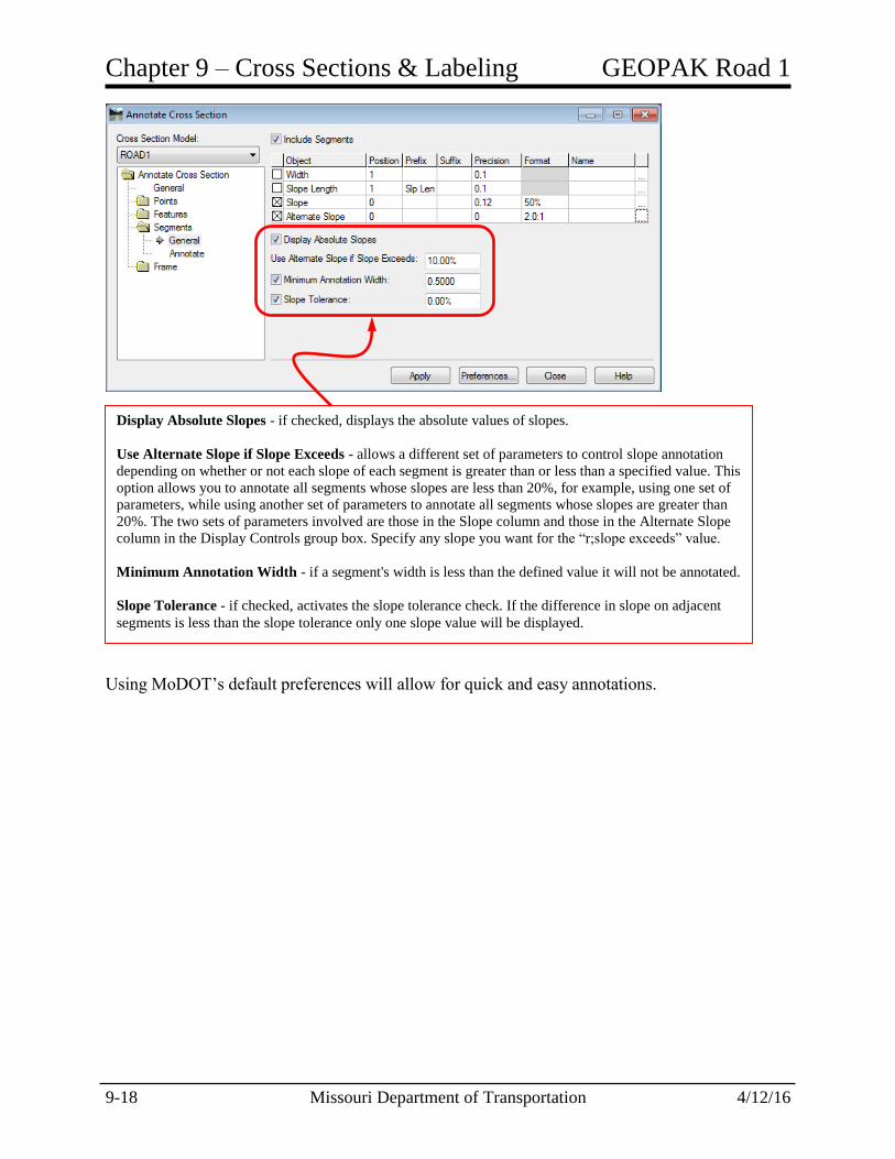
Using MoDOT’s default preferences will allow for quick and easy annotations.
Display Absolute Slopes - if checked, displays the absolute values of slopes.
Use Alternate Slope if Slope Exceeds - allows a different set of parameters to control slope annotation
depending on whether or not each slope of each segment is greater than or less than a specified value. This
option allows you to annotate all segments whose slopes are less than 20%, for example, using one set of
parameters, while using another set of parameters to annotate all segments whose slopes are greater than
20%. The two sets of parameters involved are those in the Slope column and those in the Alternate Slope
column in the Display Controls group box. Specify any slope you want for the “r;slope exceeds” value.
Minimum Annotation Width - if a segment's width is less than the defined value it will not be annotated.
Slope Tolerance - if checked, activates the slope tolerance check. If the difference in slope on adjacent
segments is less than the slope tolerance only one slope value will be displayed.

GEOPAK Road 1 Chapter 9 – Cross Sections & Labeling
4/12/16 Missouri Department of Transportation 9-19
9.6 Cross Section Viewer
The Cross Section Viewer command windows in on specified cross section set in the Model.
Using the Cross Section Viewer, you can view a single cross section, or you can view in
succession each cross section in a model. The latter method, called Movie Mode, displays each
cross section for a specified time.
Dialog Options
Cross Section Model defines which set of cross sections to view. Select one of the available
models.
Horizontal Alignment displays the horizontal alignment associated with the selected cross
section.
Zoom Factor defines the zoom factor for adjusting the drawing file view. Enter a value greater
than 1.0 to zoom out from the cross sections. Enter a value less than 1.0 to zoom in toward the
cross sections. Only applies to the cross section view.
Plan View shows the plan location of the cross section viewed. Draws a temporary line in the
plan view where the cross section is located and centers that line in the plan view.
Movie Mode Time specifies the time for viewing each cross section in the selected cross section
set. You can enter time values in tenths of a second.
Run starts the movie mode of the cross section viewer. Selecting the <Esc> cancels the run
Cross Sections lists each cross section in the selected cross section set. Select a single cross
section to immediately view it
Chapter 9 – Cross Sections & Labeling GEOPAK Road 1
9-20 Missouri Department of Transportation 4/12/16
9.7 Group Exercise: Cutting Road1 Cross Sections and Annotation
Create a New Cross Section Design File
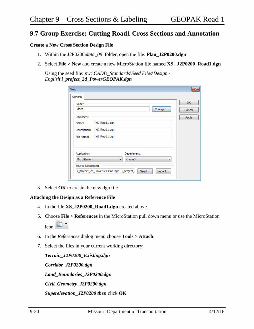
1. Within the J2P0200\data_09 folder, open the file: Plan_J2P0200.dgn
2. Select File > New and create a new MicroStation file named XS_ J2P0200_Road1.dgn
Using the seed file: pw:\CADD_Standards\Seed Files\Design -
English\i_project_2d_PowerGEOPAK.dgn
3. Select OK to create the new dgn file.
Attaching the Design as a Reference File
4. In the file XS_J2P0200_Road1.dgn created above.
5. Choose File > References in the MicroStation pull down menu or use the MicroStation
icon .
6. In the References dialog menu choose Tools > Attach.
7. Select the files in your current working directory;
Terrain_J2P0200_Existing.dgn
Corridor_J2P0200.dgn
Land_Boundaries_J2P0200.dgn
Civil_Geometry_J2P0200.dgn
Superelevation_J2P0200 then click OK

GEOPAK Road 1 Chapter 9 – Cross Sections & Labeling
4/12/16 Missouri Department of Transportation 9-21
8. Close the References dialog.
9. MicroStation Fit View to pan to the project location.
10. With the Element Selection tool, data point on the Existing ground perimeter and set the
Existing terrain model as the Active Terrain Model using the heads up display.
11. Window in to the Road1 corridor.
Create the Cross Sections
12. Continue in the same design file XS_J2P0200_Road1.dgn.
13. From the Corridor Modeling tasks group, select the
Create Cross Sections command
14. When prompted to Locate Alignment, data point on the
centerline of Road1.
15. Located at the bottom of the Create Cross Section
dialog, select Preferences.
16. In the Preferences dialog select the preference titled Sheet – 10 Scale.
17. In the Preferences dialog, click Load to utilize the selected preferences in the previous
step.

Chapter 9 – Cross Sections & Labeling GEOPAK Road 1
9-22 Missouri Department of Transportation 4/12/16
Preferences are predefined settings stored in the active XIN settings file. These
preferences will be used for creating, annotating and computing end area volumes on
proposed cross sections.
18. Close the Preferences selection dialog.
19. In the Create Cross Section dialog, complete the General settings as shown.
Note: Once the predefined Preferences are loaded, the General tab will default to the
beginning and ending stations and will create perpendicular cross sections. In the event
the project requires custom cross section locations, the Custom tab allows for a multitude
of settings to accommodate many different scenarios.

GEOPAK Road 1 Chapter 9 – Cross Sections & Labeling
4/12/16 Missouri Department of Transportation 9-23
20. Open the Sheet leaf (folder) and select the Annotation option. Change the Tag Values to
include the following:
Route = ROAD1
District = NE
County = RANDOLPH
Job No. = J2P0200
Contract ID = (leave blank)
Project No. = (leave blank)
Bridge No. = (leave blank)
Info 1 = CROSS SECTION SHEETS
Info 2 = ROAD1 CONSTRUCTION
Sheet No. = (use default)
Total Sheets = (use default)
Sheet Of = (use default)
21. In the Create Cross Section dialog, click Apply to create the cross sections into a new
DGN Drawing Model entitled ROAD1.
22. Close the Create Cross Section dialog after the cross sections have been generated.
Note: New cross sections will need to be created if edits are needed. This may be done in the
Cross Section Model if the tool is still open but if the tool has been closed then you will need to
open the Default Model.

Chapter 9 – Cross Sections & Labeling GEOPAK Road 1
9-24 Missouri Department of Transportation 4/12/16
View the Cross Sections
23. Continue in the same design file XS_Road1.dgn.
24. From the Corridor Modeling task group, select the Cross Section Viewer tool.
25. In the Cross Section Viewer dialog, verify the Cross Section Model: setting is set to your
active Cross Section Drawing Model Road1.
26. Populate the Cross Section Viewer dialog as shown.
27. Select Run to automatically scan through the cross sections.
28. Now select any individual cross section station from the list and notice how the view
updates to the selected cross section station value.
29. Close the Cross Section Viewer dialog.
Annotate the Cross Sections
30. Continue in the same design file XS_Road1.dgn.
31. From the Corridor Modeling task group, select the Annotate Cross Sections tool.
32. Located at the bottom of the Annotate Cross
Section dialog, click Preferences.
33. In the Preferences dialog, select the preference
entitled MODOT-Off/Elev/Slope.
34. In the Preferences dialog click Load, to utilize
the selected preferences in the previous step.
Preferences are predefined settings stored in the
active XIN settings file. These preferences will
be used for creating, annotating and computing
end area volumes on proposed cross sections.
35. Close the Preferences dialog.
GEOPAK Road 1 Chapter 9 – Cross Sections & Labeling
4/12/16 Missouri Department of Transportation 9-25
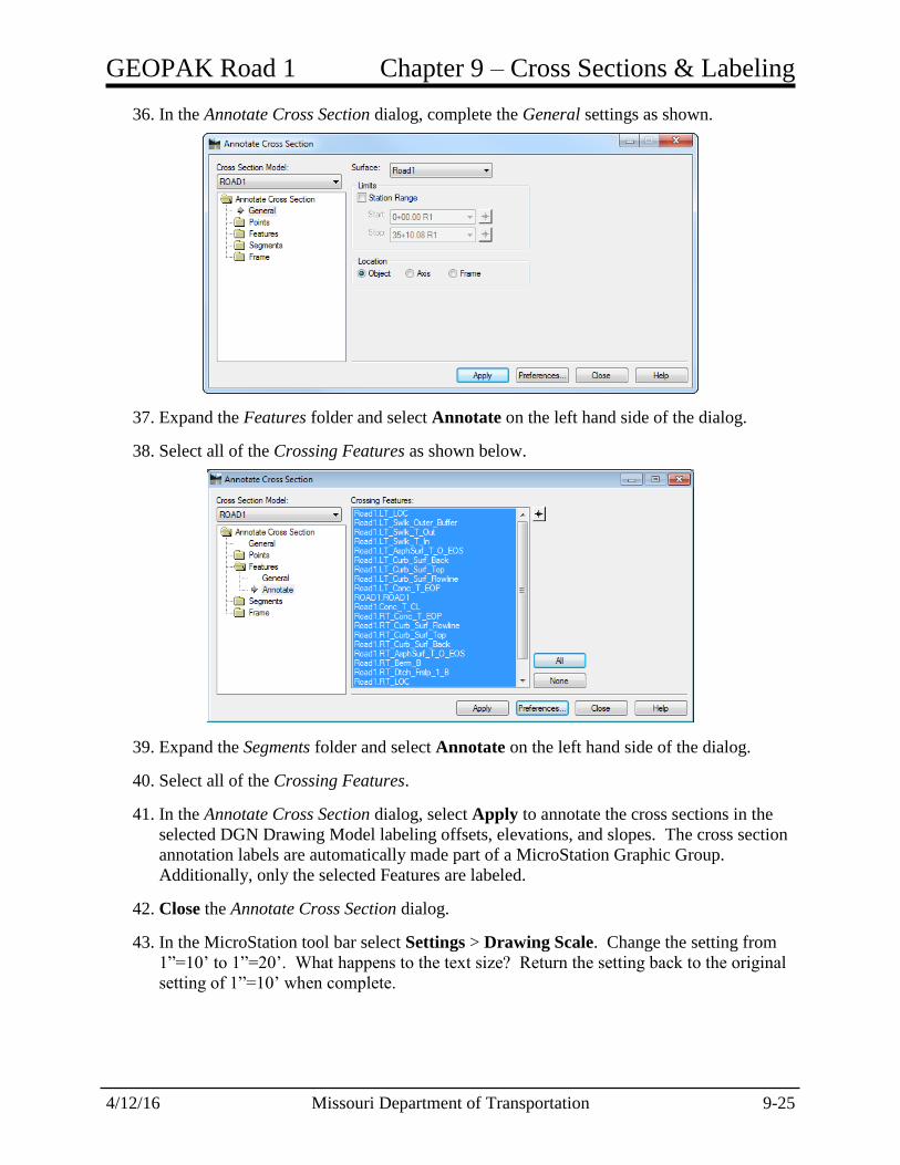
36. In the Annotate Cross Section dialog, complete the General settings as shown.
37. Expand the Features folder and select Annotate on the left hand side of the dialog.
38. Select all of the Crossing Features as shown below.
39. Expand the Segments folder and select Annotate on the left hand side of the dialog.
40. Select all of the Crossing Features.
41. In the Annotate Cross Section dialog, select Apply to annotate the cross sections in the
selected DGN Drawing Model labeling offsets, elevations, and slopes. The cross section
annotation labels are automatically made part of a MicroStation Graphic Group.
Additionally, only the selected Features are labeled.
42. Close the Annotate Cross Section dialog.
43. In the MicroStation tool bar select Settings > Drawing Scale. Change the setting from
1”=10’ to 1”=20’. What happens to the text size? Return the setting back to the original
setting of 1”=10’ when complete.

Chapter 9 – Cross Sections & Labeling GEOPAK Road 1
9-26 Missouri Department of Transportation 4/12/16
9.8 Individual Exercise 5-1: Cutting Route 63 Cross Sections and
Annotation
Create a new Cross Section Design File
1. Select File > New and create a new MicroStation file named XS_J2P0200_Route63.dgn
Using the seed file: pw:\CADD_Standards\Seed Files\Design -
English\i_project_2d_PowerGEOPAK.dgn
2. Select OK to create the new dgn file.
Attaching the Design as a Reference File
3. In the file XS_J2P0200_Route63.dgn created above.
4. Choose File > References in the MicroStation pull down menu or use the MicroStation
icon .
5. In the References dialog menu choose Tools > Attach.
6. Select the files in your current working directory;
Terrain_J2P0200_Existing.dgn
Corridor_J2P0200.dgn
Civil_Geometry_J2P0200.dgn
Land_Boundaries_J2P0200.dgn
Superelevation_J2P0200 then click OK
7. Close the References dialog.
GEOPAK Road 1 Chapter 9 – Cross Sections & Labeling
4/12/16 Missouri Department of Transportation 9-27
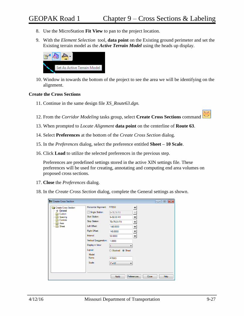
8. Use the MicroStation Fit View to pan to the project location.
9. With the Element Selection tool, data point on the Existing ground perimeter and set the
Existing terrain model as the Active Terrain Model using the heads up display.
10. Window in towards the bottom of the project to see the area we will be identifying on the
alignment.
Create the Cross Sections
11. Continue in the same design file XS_Route63.dgn.
12. From the Corridor Modeling tasks group, select Create Cross Sections command
13. When prompted to Locate Alignment data point on the centerline of Route 63.
14. Select Preferences at the bottom of the Create Cross Section dialog.
15. In the Preferences dialog, select the preference entitled Sheet – 10 Scale.
16. Click Load to utilize the selected preferences in the previous step.
Preferences are predefined settings stored in the active XIN settings file. These
preferences will be used for creating, annotating and computing end area volumes on
proposed cross sections.
17. Close the Preferences dialog.
18. In the Create Cross Section dialog, complete the General settings as shown.

Chapter 9 – Cross Sections & Labeling GEOPAK Road 1
9-28 Missouri Department of Transportation 4/12/16
Note: Once the predefined Preferences are loaded, the General tab will default to the
beginning and ending stations and will create perpendicular cross sections. In the event
the project requires custom cross section locations, the Custom tab allows for a multitude
of settings to accommodate many different scenarios.
19. Open the Sheet leaf (folder) and select the Annotation option. Change the Tag Values to
include the following:
Route = RTE63
District = NE
County = RANDOLPH
Job No. = J2P0200
Contract ID = (leave blank)
Project No. = (leave blank)
Bridge No. = (leave blank)
Info 1 = CROSS SECTION SHEETS
Info 2 = ROUTE 63 CONSTRUCTION
Sheet No. = (use default)
Total Sheets = (use default)
Sheet Of = (use default)
20. In the Create Cross Section dialog, click Apply to create the cross sections into a new
DGN Drawing Model entitled ROUTE63.
Select the Tag Name
Input the Value
Click Update button
Value has been updated

GEOPAK Road 1 Chapter 9 – Cross Sections & Labeling
4/12/16 Missouri Department of Transportation 9-29
21. Close the Create Cross Section dialog after the cross sections have been generated.
View the Cross Sections
22. Continue in the same design file XS_Route63.dgn.
23. From the Corridor Modeling task group, select the Cross Section Viewer tool.
24. In the Cross Section Viewer dialog, verify the Cross Section Model: setting is set to your
active Cross Section Drawing Model RTE63.
25. Populate the Cross Section Viewer dialog as shown.
26. Select Run to automatically scan through the cross sections.
27. Now select any individual cross section station from the list and notice how the view
updates to the selected cross section station value.
28. Close the Cross Section Viewer dialog.
Annotate the Cross Sections
29. Continue in the same design file XS_Route63.dgn.
30. From the Corridor Modeling task group, select the Annotate Cross Sections tool.
31. Located at the bottom of the Annotate Cross Section dialog, click Preferences.
32. In the Preferences dialog select the preference entitled MODOT-Off/Elev/Slope.
33. In the Preferences dialog select Load, to utilize the selected preferences in the previous
step.
34. Close the Preferences dialog.
Chapter 9 – Cross Sections & Labeling GEOPAK Road 1
9-30 Missouri Department of Transportation 4/12/16
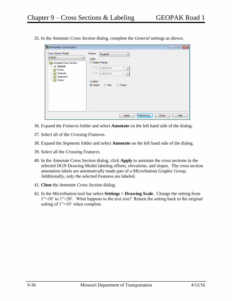
35. In the Annotate Cross Section dialog, complete the General settings as shown.
36. Expand the Features folder and select Annotate on the left hand side of the dialog.
37. Select all of the Crossing Features.
38. Expand the Segments folder and select Annotate on the left hand side of the dialog.
39. Select all the Crossing Features.
40. In the Annotate Cross Section dialog, click Apply to annotate the cross sections in the
selected DGN Drawing Model labeling offsets, elevations, and slopes. The cross section
annotation labels are automatically made part of a MicroStation Graphic Group.
Additionally, only the selected Features are labeled.
41. Close the Annotate Cross Section dialog.
42. In the MicroStation tool bar select Settings > Drawing Scale. Change the setting from
1”=10’ to 1”=20’. What happens to the text size? Return the setting back to the original
setting of 1”=10’ when complete.