chapter 8, problem 1. - unlvchapter 8, problem 1. for the circuit in fig. 8.62, ... solution 1. (a)...
TRANSCRIPT

PROPRIETARY MATERIAL. © 2007 The McGraw-Hill Companies, Inc. All rights reserved. No part
of this Manual may be displayed, reproduced or distributed in any form or by any means, without the prior
written permission of the publisher, or used beyond the limited distribution to teachers and educators
permitted by McGraw-Hill for their individual course preparation. If you are a student using this Manual,
you are using it without permission.
Chapter 8, Problem 1.
For the circuit in Fig. 8.62, find:
(a) 0i and 0v ,
(b) dtdi /0 and dtdv /0 ,
(c) i and v .
Figure 8.62
For Prob. 8.1.
PROPRIETARY MATERIAL. © 2007 The McGraw-Hill Companies, Inc. All rights reserved. No part
of this Manual may be displayed, reproduced or distributed in any form or by any means, without the prior
written permission of the publisher, or used beyond the limited distribution to teachers and educators
permitted by McGraw-Hill for their individual course preparation. If you are a student using this Manual,
you are using it without permission.
Chapter 8, Solution 1.
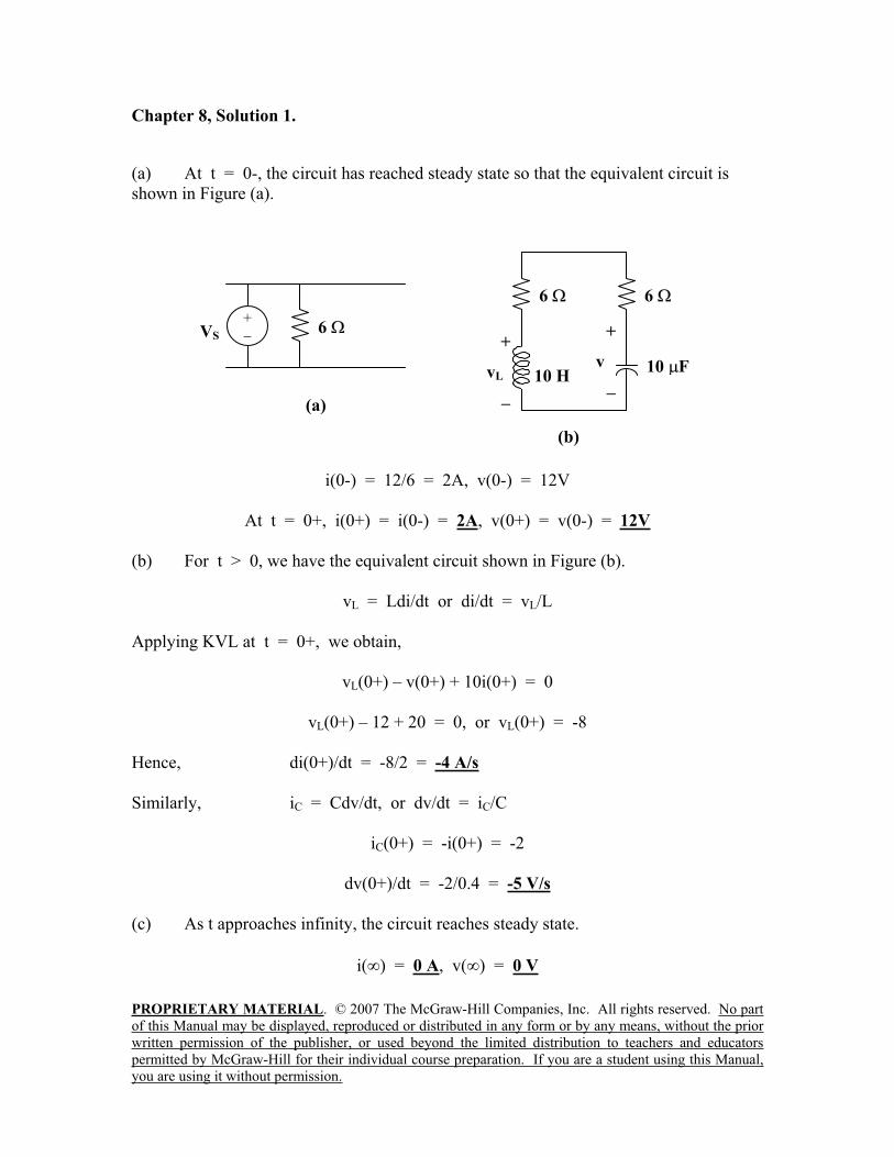
(a) At t = 0-, the circuit has reached steady state so that the equivalent circuit is
shown in Figure (a).
i(0-) = 12/6 = 2A, v(0-) = 12V
At t = 0+, i(0+) = i(0-) = 2A, v(0+) = v(0-) = 12V
(b) For t > 0, we have the equivalent circuit shown in Figure (b).
vL = Ldi/dt or di/dt = vL/L
Applying KVL at t = 0+, we obtain,
vL(0+) – v(0+) + 10i(0+) = 0
vL(0+) – 12 + 20 = 0, or vL(0+) = -8
Hence, di(0+)/dt = -8/2 = -4 A/s
Similarly, iC = Cdv/dt, or dv/dt = iC/C
iC(0+) = -i(0+) = -2
dv(0+)/dt = -2/0.4 = -5 V/s
(c) As t approaches infinity, the circuit reaches steady state.
i( ) = 0 A, v( ) = 0 V
VS
+6
(a)
(b)
+
v10 H
10 F
6 6
+
vL
PROPRIETARY MATERIAL. © 2007 The McGraw-Hill Companies, Inc. All rights reserved. No part
of this Manual may be displayed, reproduced or distributed in any form or by any means, without the prior
written permission of the publisher, or used beyond the limited distribution to teachers and educators
permitted by McGraw-Hill for their individual course preparation. If you are a student using this Manual,
you are using it without permission.
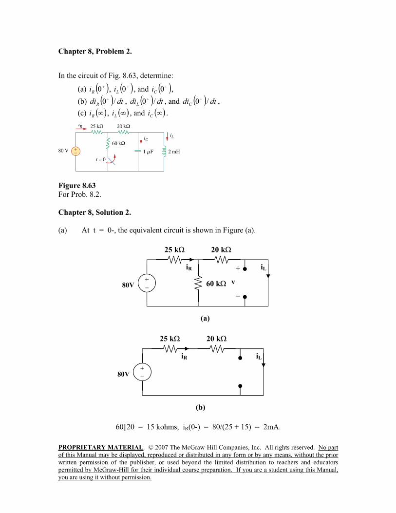
Chapter 8, Problem 2.
In the circuit of Fig. 8.63, determine:
(a) 0Ri , 0
Li , and 0
Ci ,
(b) dtdiR
/0 , dtdiL
/0 , and dtdiC
/0 ,
(c)Ri ,
Li , and
Ci .
Figure 8.63
For Prob. 8.2.
Chapter 8, Solution 2.
(a) At t = 0-, the equivalent circuit is shown in Figure (a).
60||20 = 15 kohms, iR(0-) = 80/(25 + 15) = 2mA.
20 k
60 k
(a)
iL+
v80V
+
25 k
iR
20 k
(b)
iL
80V+
25 k
iR

PROPRIETARY MATERIAL. © 2007 The McGraw-Hill Companies, Inc. All rights reserved. No part
of this Manual may be displayed, reproduced or distributed in any form or by any means, without the prior
written permission of the publisher, or used beyond the limited distribution to teachers and educators
permitted by McGraw-Hill for their individual course preparation. If you are a student using this Manual,
you are using it without permission.
By the current division principle,
iL(0-) = 60(2mA)/(60 + 20) = 1.5 mA
vC(0-) = 0
At t = 0+,
vC(0+) = vC(0-) = 0
iL(0+) = iL(0-) = 1.5 mA
80 = iR(0+)(25 + 20) + vC(0-)
iR(0+) = 80/45k = 1.778 mA
But, iR = iC + iL
1.778 = iC(0+) + 1.5 or iC(0+) = 0.278 mA
(b) vL(0+) = vC(0+) = 0
But, vL = LdiL/dt and diL(0+)/dt = vL(0+)/L = 0
diL(0+)/dt = 0
Again, 80 = 45iR + vC
0 = 45diR/dt + dvC/dt
But, dvC(0+)/dt = iC(0+)/C = 0.278 mohms/1 F = 278 V/s
Hence, diR(0+)/dt = (-1/45)dvC(0+)/dt = -278/45
diR(0+)/dt = -6.1778 A/s
Also, iR = iC + iL
diR(0+)/dt = diC(0+)/dt + diL(0+)/dt
-6.1788 = diC(0+)/dt + 0, or diC(0+)/dt = -6.1788 A/s
(c) As t approaches infinity, we have the equivalent circuit in Figure (b).
iR( ) = iL( ) = 80/45k = 1.778 mA
iC( ) = Cdv( )/dt = 0.
PROPRIETARY MATERIAL. © 2007 The McGraw-Hill Companies, Inc. All rights reserved. No part
of this Manual may be displayed, reproduced or distributed in any form or by any means, without the prior
written permission of the publisher, or used beyond the limited distribution to teachers and educators
permitted by McGraw-Hill for their individual course preparation. If you are a student using this Manual,
you are using it without permission.
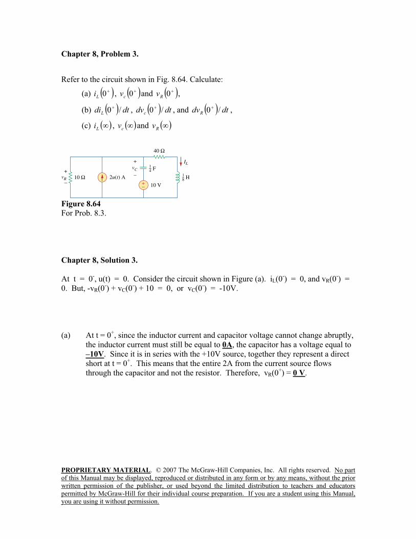
Chapter 8, Problem 3.
Refer to the circuit shown in Fig. 8.64. Calculate:
(a) 0Li , 0
cv and 0
Rv ,
(b) dtdiL
/0 , dtdvc
/0 , and dtdvR
/0 ,
(c)Li ,
cv and
Rv
Figure 8.64
For Prob. 8.3.
Chapter 8, Solution 3.
At t = 0-, u(t) = 0. Consider the circuit shown in Figure (a). iL(0
-) = 0, and vR(0
-) =
0. But, -vR(0-) + vC(0
-) + 10 = 0, or vC(0
-) = -10V.
(a) At t = 0+, since the inductor current and capacitor voltage cannot change abruptly,
the inductor current must still be equal to 0A, the capacitor has a voltage equal to
–10V. Since it is in series with the +10V source, together they represent a direct
short at t = 0+. This means that the entire 2A from the current source flows
through the capacitor and not the resistor. Therefore, vR(0+) = 0 V.
PROPRIETARY MATERIAL. © 2007 The McGraw-Hill Companies, Inc. All rights reserved. No part
of this Manual may be displayed, reproduced or distributed in any form or by any means, without the prior
written permission of the publisher, or used beyond the limited distribution to teachers and educators
permitted by McGraw-Hill for their individual course preparation. If you are a student using this Manual,
you are using it without permission.
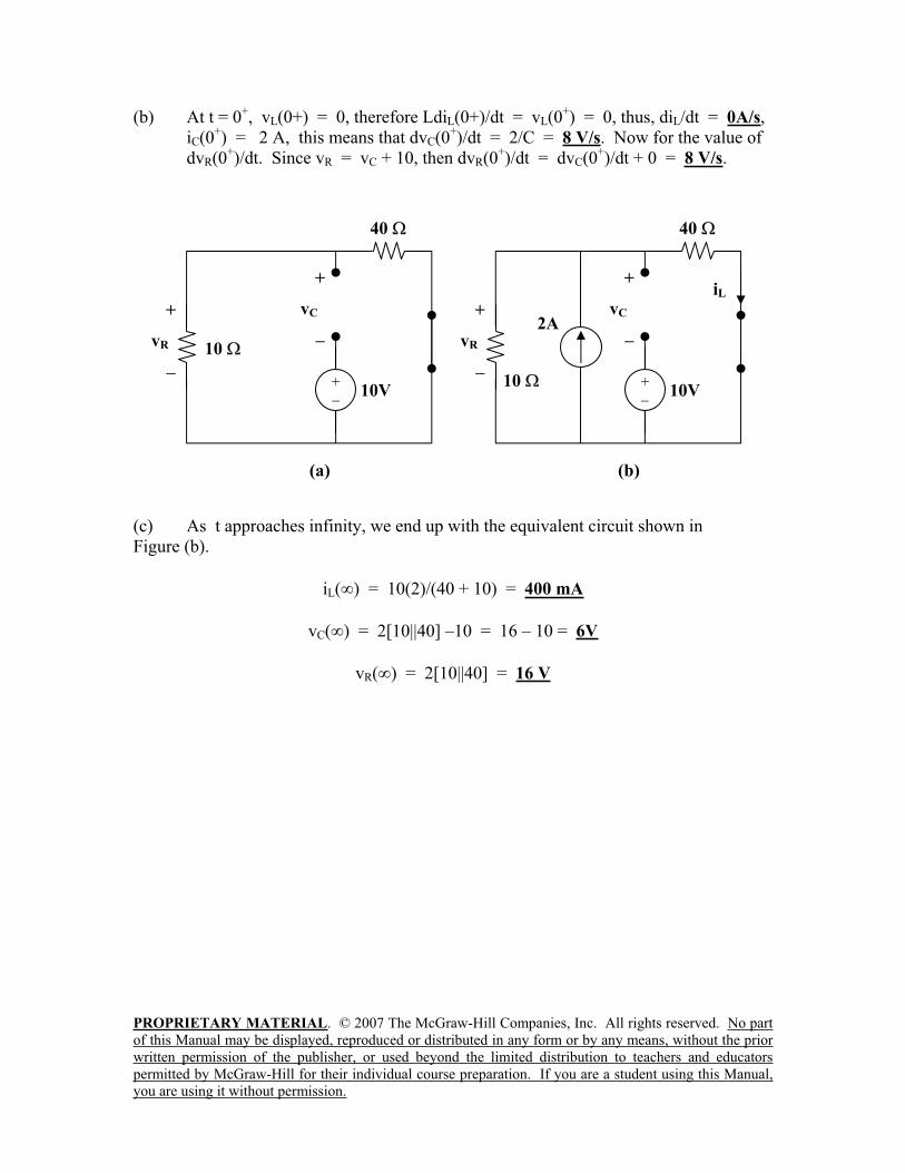
(b) At t = 0+, vL(0+) = 0, therefore LdiL(0+)/dt = vL(0
+) = 0, thus, diL/dt = 0A/s,
iC(0+) = 2 A, this means that dvC(0
+)/dt = 2/C = 8 V/s. Now for the value of
dvR(0+)/dt. Since vR = vC + 10, then dvR(0
+)/dt = dvC(0
+)/dt + 0 = 8 V/s.
(c) As t approaches infinity, we end up with the equivalent circuit shown in
Figure (b).
iL( ) = 10(2)/(40 + 10) = 400 mA
vC( ) = 2[10||40] –10 = 16 – 10 = 6V
vR( ) = 2[10||40] = 16 V
40
10
(a)
+
vC
10V+
+
vR
+
vR
iL
2A
40
10
(b)
+
vC
10V+

PROPRIETARY MATERIAL. © 2007 The McGraw-Hill Companies, Inc. All rights reserved. No part
of this Manual may be displayed, reproduced or distributed in any form or by any means, without the prior
written permission of the publisher, or used beyond the limited distribution to teachers and educators
permitted by McGraw-Hill for their individual course preparation. If you are a student using this Manual,
you are using it without permission.
Chapter 8, Problem 4.
In the circuit of Fig. 8.65, find:
(a) 0v and 0i ,
(b) dtdv /0 and dtdi /0 ,
(c) v and i .
Figure 8.65
For Prob. 8.4.
Chapter 8, Solution 4.
(a) At t = 0-, u(-t) = 1 and u(t) = 0 so that the equivalent circuit is shown in
Figure (a).
i(0-) = 40/(3 + 5) = 5A, and v(0
-) = 5i(0
-) = 25V.
Hence, i(0+) = i(0
-) = 5A
v(0+) = v(0
-) = 25V
3
5
(a)
i+
v40V
+
4 A
0.1F
3
5
(b)
i + vL
40V+
0.25 H
iC iR
PROPRIETARY MATERIAL. © 2007 The McGraw-Hill Companies, Inc. All rights reserved. No part
of this Manual may be displayed, reproduced or distributed in any form or by any means, without the prior
written permission of the publisher, or used beyond the limited distribution to teachers and educators
permitted by McGraw-Hill for their individual course preparation. If you are a student using this Manual,
you are using it without permission.
(b) iC = Cdv/dt or dv(0+)/dt = iC(0
+)/C
For t = 0+, 4u(t) = 4 and 4u(-t) = 0. The equivalent circuit is shown in Figure (b).
Since i and v cannot change abruptly,
iR = v/5 = 25/5 = 5A, i(0+) + 4 =iC(0
+) + iR(0
+)
5 + 4 = iC(0+) + 5 which leads to iC(0
+) = 4
dv(0+)/dt = 4/0.1 = 40 V/s
Similarly, vL = Ldi/dt which leads to di(0+)/dt = vL(0
+)/L
3i(0+) + vL(0
+) + v(0
+) = 0
15 + vL(0+) + 25 = 0 or vL(0
+) = -40
di(0+)/dt = -40/0.25 = -160 A/s
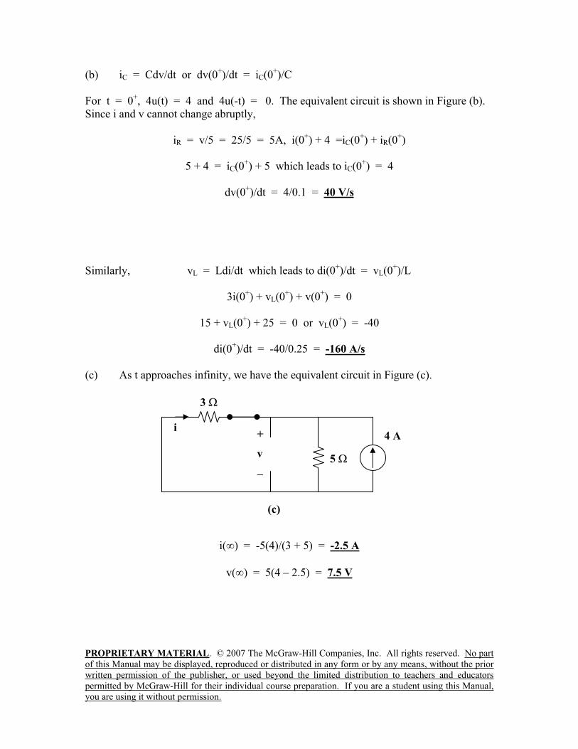
(c) As t approaches infinity, we have the equivalent circuit in Figure (c).
i( ) = -5(4)/(3 + 5) = -2.5 A
v( ) = 5(4 – 2.5) = 7.5 V
4 A
3
5
(c)
i+
v
PROPRIETARY MATERIAL. © 2007 The McGraw-Hill Companies, Inc. All rights reserved. No part
of this Manual may be displayed, reproduced or distributed in any form or by any means, without the prior
written permission of the publisher, or used beyond the limited distribution to teachers and educators
permitted by McGraw-Hill for their individual course preparation. If you are a student using this Manual,
you are using it without permission.
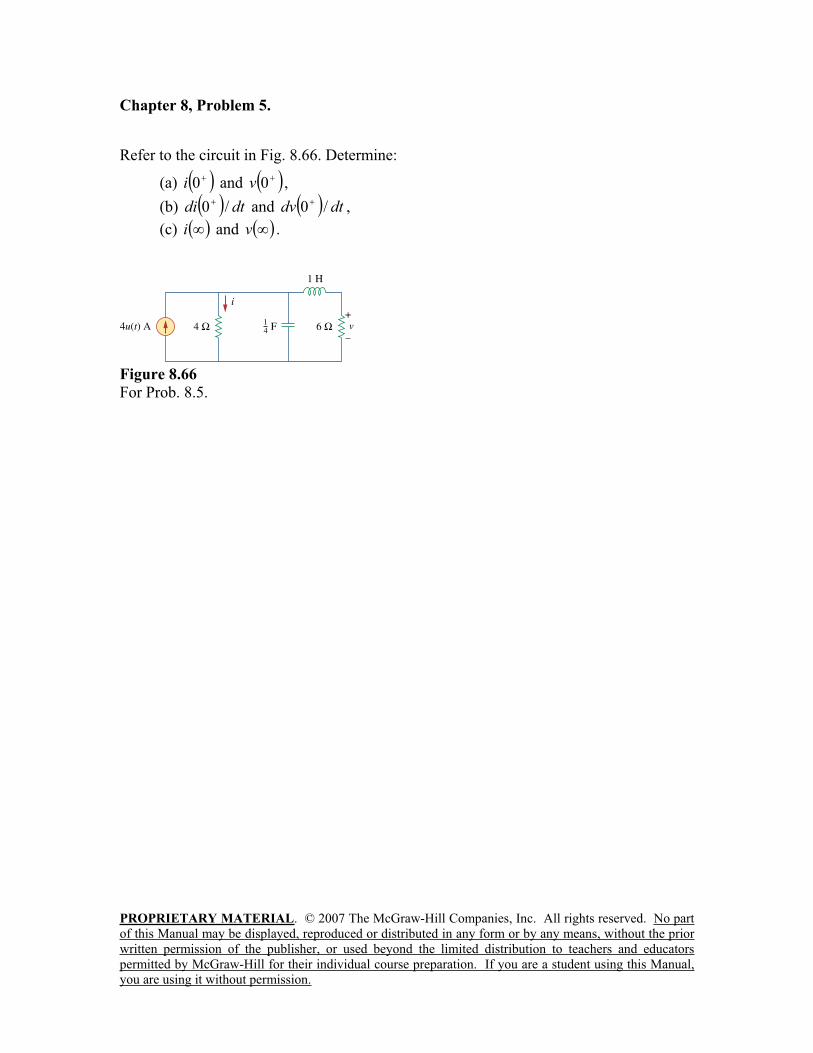
Chapter 8, Problem 5.
Refer to the circuit in Fig. 8.66. Determine:
(a) 0i and 0v ,
(b) dtdi /0 and dtdv /0 ,
(c) i and v .
Figure 8.66
For Prob. 8.5.
PROPRIETARY MATERIAL. © 2007 The McGraw-Hill Companies, Inc. All rights reserved. No part
of this Manual may be displayed, reproduced or distributed in any form or by any means, without the prior
written permission of the publisher, or used beyond the limited distribution to teachers and educators
permitted by McGraw-Hill for their individual course preparation. If you are a student using this Manual,
you are using it without permission.
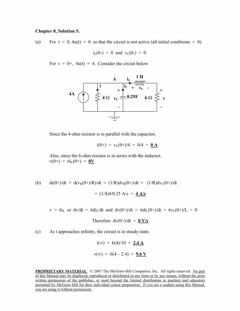
Chapter 8, Solution 5.
(a) For t < 0, 4u(t) = 0 so that the circuit is not active (all initial conditions = 0).
iL(0-) = 0 and vC(0-) = 0.
For t = 0+, 4u(t) = 4. Consider the circuit below.
Since the 4-ohm resistor is in parallel with the capacitor,
i(0+) = vC(0+)/4 = 0/4 = 0 A
Also, since the 6-ohm resistor is in series with the inductor,
v(0+) = 6iL(0+) = 0V.
(b) di(0+)/dt = d(vR(0+)/R)/dt = (1/R)dvR(0+)/dt = (1/R)dvC(0+)/dt
= (1/4)4/0.25 A/s = 4 A/s
v = 6iL or dv/dt = 6diL/dt and dv(0+)/dt = 6diL(0+)/dt = 6vL(0+)/L = 0
Therefore dv(0+)/dt = 0 V/s
(c) As t approaches infinity, the circuit is in steady-state.
i( ) = 6(4)/10 = 2.4 A
v( ) = 6(4 – 2.4) = 9.6 V
6
i
A
+
vC0.25F
4A4
+
v
1 H
+ vLiC
iL
PROPRIETARY MATERIAL. © 2007 The McGraw-Hill Companies, Inc. All rights reserved. No part
of this Manual may be displayed, reproduced or distributed in any form or by any means, without the prior
written permission of the publisher, or used beyond the limited distribution to teachers and educators
permitted by McGraw-Hill for their individual course preparation. If you are a student using this Manual,
you are using it without permission.
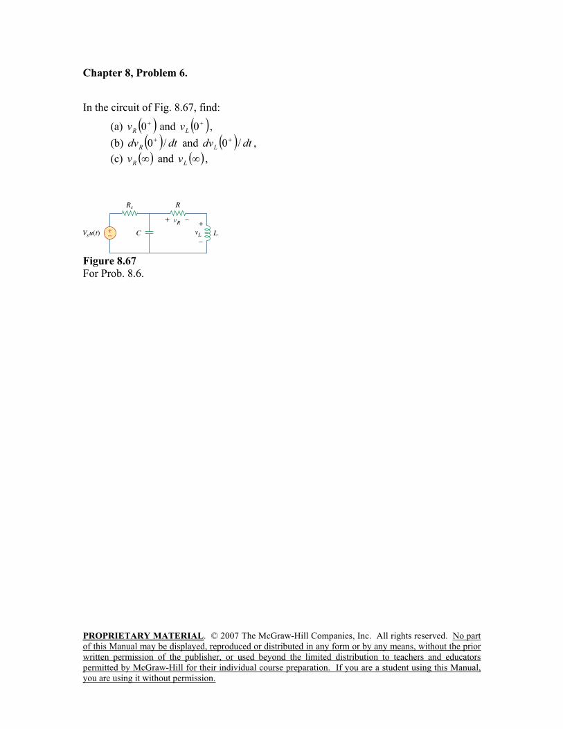
Chapter 8, Problem 6.
In the circuit of Fig. 8.67, find:
(a) 0Rv and 0
Lv ,
(b) dtdvR
/0 and dtdvL
/0 ,
(c)Rv and
Lv ,
Figure 8.67
For Prob. 8.6.
PROPRIETARY MATERIAL. © 2007 The McGraw-Hill Companies, Inc. All rights reserved. No part
of this Manual may be displayed, reproduced or distributed in any form or by any means, without the prior
written permission of the publisher, or used beyond the limited distribution to teachers and educators
permitted by McGraw-Hill for their individual course preparation. If you are a student using this Manual,
you are using it without permission.
Chapter 8, Solution 6.
(a) Let i = the inductor current. For t < 0, u(t) = 0 so that
i(0) = 0 and v(0) = 0.
For t > 0, u(t) = 1. Since, v(0+) = v(0-) = 0, and i(0+) = i(0-) = 0.
vR(0+) = Ri(0+) = 0 V
Also, since v(0+) = vR(0+) + vL(0+) = 0 = 0 + vL(0+) or vL(0+) = 0 V.
(1)
(b) Since i(0+) = 0, iC(0+) = VS/RS
But, iC = Cdv/dt which leads to dv(0+)/dt = VS/(CRS) (2)
From (1), dv(0+)/dt = dvR(0+)/dt + dvL(0+)/dt (3)
vR = iR or dvR/dt = Rdi/dt (4)
But, vL = Ldi/dt, vL(0+) = 0 = Ldi(0+)/dt and di(0+)/dt = 0 (5)
From (4) and (5), dvR(0+)/dt = 0 V/s
From (2) and (3), dvL(0+)/dt = dv(0+)/dt = Vs/(CRs)
(c) As t approaches infinity, the capacitor acts like an open circuit, while the inductor
acts like a short circuit.
vR( ) = [R/(R + Rs)]Vs
vL( ) = 0 V
PROPRIETARY MATERIAL. © 2007 The McGraw-Hill Companies, Inc. All rights reserved. No part
of this Manual may be displayed, reproduced or distributed in any form or by any means, without the prior
written permission of the publisher, or used beyond the limited distribution to teachers and educators
permitted by McGraw-Hill for their individual course preparation. If you are a student using this Manual,
you are using it without permission.
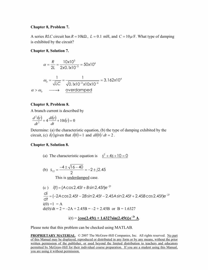
Chapter 8, Problem 7.
A series RLC circuit has k10R , 1.0L mH, and 10C F. What type of damping
is exhibited by the circuit?
Chapter 8, Solution 7.
36
3
10 1050 10
2 2 0.1 10
R xx
L x x
4
3 6
1 13.162 10
0.1 10 10 10o x
LC x x x
overdampedo
Chapter 8, Problem 8.
A branch current is described by
01042
2
tidt
tdi
dt
tid
Determine: (a) the characteristic equation, (b) the type of damping exhibited by the
circuit, (c) ti given that 10i and 2/0 dtdi .
Chapter 8, Solution 8.
(a) The characteristic equation is 2 4 10 0s s
(b) 1,2
4 16 402 2.45
2s j
This is underdamped case.
(c ) 2( ) ( cos2.45 sin2.45 ) ti t A t B t e
2( 2 cos2.45 2 sin2.45 2.45 sin2.45 2.45 cos2.45 ) tdiA t B t A t B t e
dt i(0) =1 = A
di(0)/dt = 2 = –2A + 2.45B = –2 + 2.45B or B = 1.6327
i(t) = cos(2.45t) + 1.6327sin(2.45t)e–2t
A.
Please note that this problem can be checked using MATLAB.
PROPRIETARY MATERIAL. © 2007 The McGraw-Hill Companies, Inc. All rights reserved. No part
of this Manual may be displayed, reproduced or distributed in any form or by any means, without the prior
written permission of the publisher, or used beyond the limited distribution to teachers and educators
permitted by McGraw-Hill for their individual course preparation. If you are a student using this Manual,
you are using it without permission.
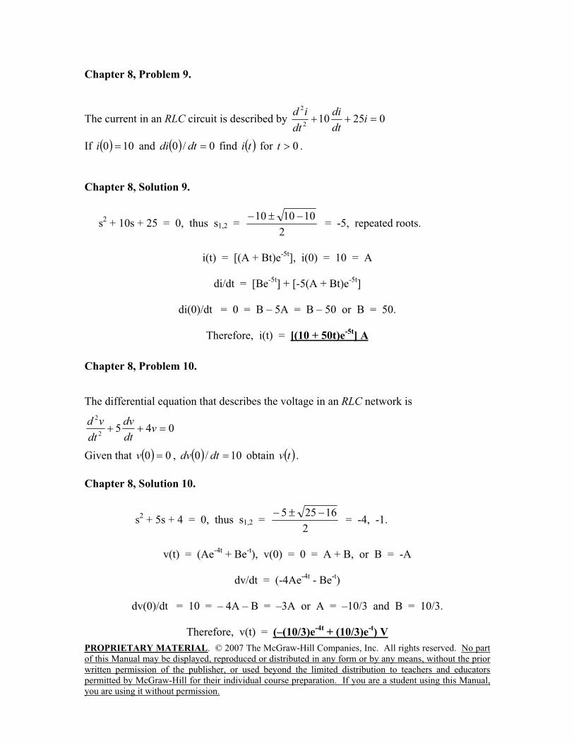
Chapter 8, Problem 9.
The current in an RLC circuit is described by 025102
2
idt
di
dt
id
If 100i and 0/0 dtdi find ti for 0t .
Chapter 8, Solution 9.
s2 + 10s + 25 = 0, thus s1,2 =
2
101010 = -5, repeated roots.
i(t) = [(A + Bt)e-5t
], i(0) = 10 = A
di/dt = [Be-5t
] + [-5(A + Bt)e-5t
]
di(0)/dt = 0 = B – 5A = B – 50 or B = 50.
Therefore, i(t) = [(10 + 50t)e-5t
] A
Chapter 8, Problem 10.
The differential equation that describes the voltage in an RLC network is
0452
2
vdt
dv
dt
vd
Given that 00v , 10/0 dtdv obtain tv .
Chapter 8, Solution 10.
s2 + 5s + 4 = 0, thus s1,2 =
2
16255 = -4, -1.
v(t) = (Ae-4t
+ Be-t), v(0) = 0 = A + B, or B = -A
dv/dt = (-4Ae-4t
- Be-t)
dv(0)/dt = 10 = – 4A – B = –3A or A = –10/3 and B = 10/3.
Therefore, v(t) = (–(10/3)e-4t
+ (10/3)e-t) V
PROPRIETARY MATERIAL. © 2007 The McGraw-Hill Companies, Inc. All rights reserved. No part
of this Manual may be displayed, reproduced or distributed in any form or by any means, without the prior
written permission of the publisher, or used beyond the limited distribution to teachers and educators
permitted by McGraw-Hill for their individual course preparation. If you are a student using this Manual,
you are using it without permission.
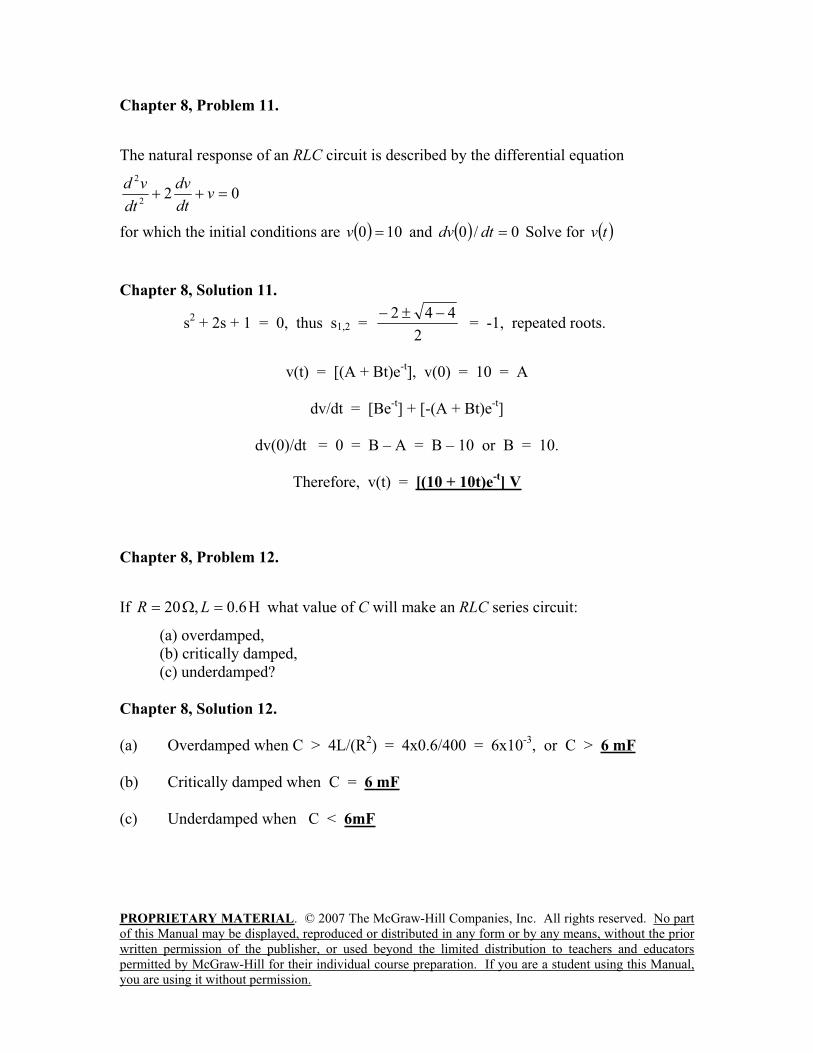
Chapter 8, Problem 11.
The natural response of an RLC circuit is described by the differential equation
022
2
vdt
dv
dt
vd
for which the initial conditions are 100v and 0/0 dtdv Solve for tv
Chapter 8, Solution 11.
s2 + 2s + 1 = 0, thus s1,2 =
2
442 = -1, repeated roots.
v(t) = [(A + Bt)e-t], v(0) = 10 = A
dv/dt = [Be-t] + [-(A + Bt)e
-t]
dv(0)/dt = 0 = B – A = B – 10 or B = 10.
Therefore, v(t) = [(10 + 10t)e-t] V
Chapter 8, Problem 12.
If 6.0,20 LR what value of C will make an RLC series circuit:
(a) overdamped,
(b) critically damped,
(c) underdamped?
Chapter 8, Solution 12.
(a) Overdamped when C > 4L/(R2) = 4x0.6/400 = 6x10
-3, or C > 6 mF
(b) Critically damped when C = 6 mF
(c) Underdamped when C < 6mF
PROPRIETARY MATERIAL. © 2007 The McGraw-Hill Companies, Inc. All rights reserved. No part
of this Manual may be displayed, reproduced or distributed in any form or by any means, without the prior
written permission of the publisher, or used beyond the limited distribution to teachers and educators
permitted by McGraw-Hill for their individual course preparation. If you are a student using this Manual,
you are using it without permission.
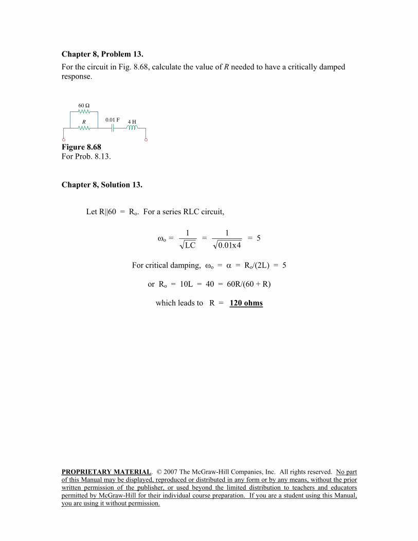
Chapter 8, Problem 13.
For the circuit in Fig. 8.68, calculate the value of R needed to have a critically damped
response.
Figure 8.68
For Prob. 8.13.
Chapter 8, Solution 13.
Let R||60 = Ro. For a series RLC circuit,
o =LC
1 =
4x01.0
1 = 5
For critical damping, o = = Ro/(2L) = 5
or Ro = 10L = 40 = 60R/(60 + R)
which leads to R = 120 ohms
PROPRIETARY MATERIAL. © 2007 The McGraw-Hill Companies, Inc. All rights reserved. No part
of this Manual may be displayed, reproduced or distributed in any form or by any means, without the prior
written permission of the publisher, or used beyond the limited distribution to teachers and educators
permitted by McGraw-Hill for their individual course preparation. If you are a student using this Manual,
you are using it without permission.
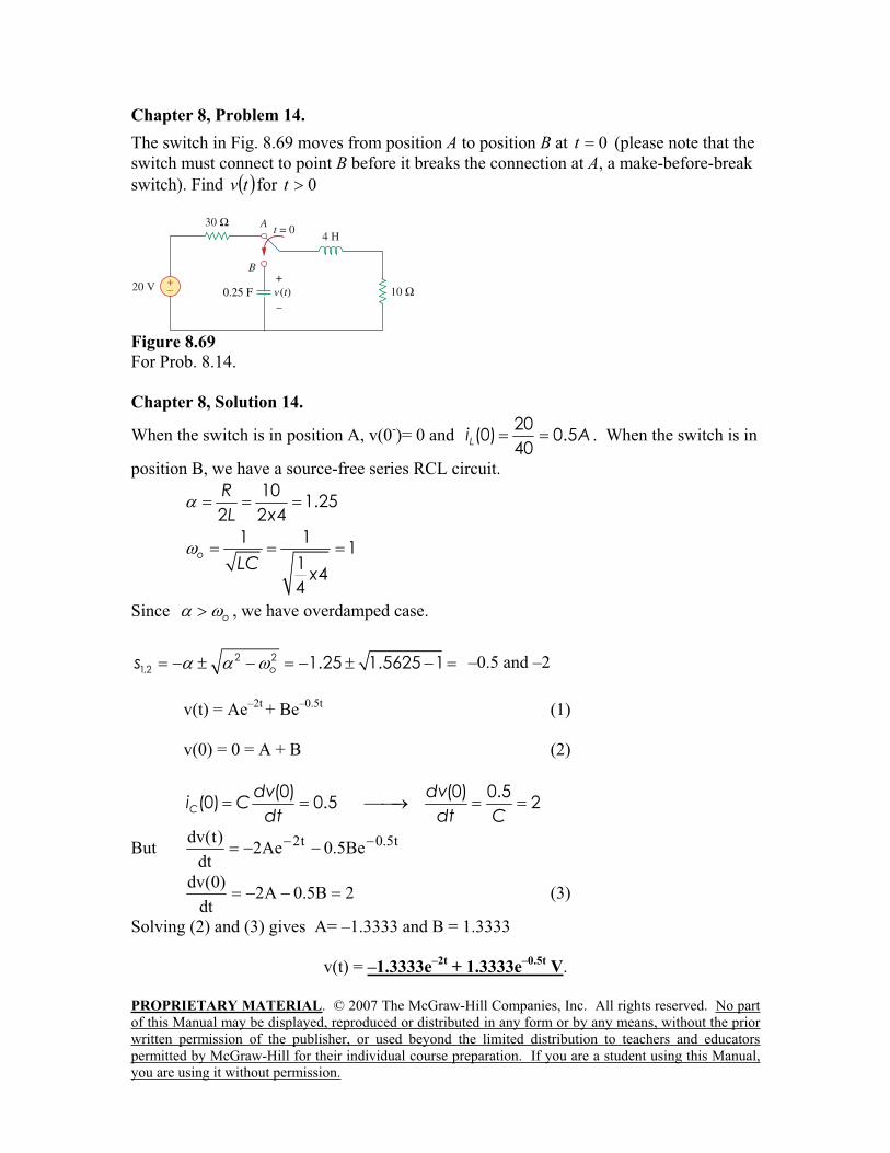
Chapter 8, Problem 14.
The switch in Fig. 8.69 moves from position A to position B at 0t (please note that the
switch must connect to point B before it breaks the connection at A, a make-before-break
switch). Find tv for 0t
Figure 8.69
For Prob. 8.14.
Chapter 8, Solution 14.
When the switch is in position A, v(0-)= 0 and
20(0) 0.5
40Li A . When the switch is in
position B, we have a source-free series RCL circuit.
101.25
2 2 4
R
L x
1 11
14
4
oLC
x
Since o , we have overdamped case.
2 2
1,2 1.25 1.5625 1 1.5664, 0.9336os
v(t) = Ae–2t
+ Be–0.5t
(1)
v(0) = 0 = A + B (2)
(0) (0) 0.5(0) 0.5 2C
dv dvi C
dt dt C
But t5.0t2 Be5.0Ae2dt
)t(dv
2B5.0A2dt
)0(dv (3)
Solving (2) and (3) gives A= –1.3333 and B = 1.3333
v(t) = –1.3333e–2t
+ 1.3333e–0.5t
V.
–0.5 and –2
PROPRIETARY MATERIAL. © 2007 The McGraw-Hill Companies, Inc. All rights reserved. No part
of this Manual may be displayed, reproduced or distributed in any form or by any means, without the prior
written permission of the publisher, or used beyond the limited distribution to teachers and educators
permitted by McGraw-Hill for their individual course preparation. If you are a student using this Manual,
you are using it without permission.
Chapter 8, Problem 15.
The responses of a series RLC circuit are
tt
ceetv
1020 301030 V
tt
Leeti
1020 6040 mA
wherecv and
Li are the capacitor voltage and inductor current, respectively. Determine
the values of R, L, and C.
Chapter 8, Solution 15.
Given that s1 = -10 and s2 = -20, we recall that
s1,2 =2
o
2 = -10, -20
Clearly, s1 + s2 = -2 = -30 or = 15 = R/(2L) or R = 60L (1)
s1 =2
o
21515 = -10 which leads to 152 – o
2 = 25
or o = 25225 = LC1200 , thus LC = 1/200 (2)
Since we have a series RLC circuit, iL = iC = CdvC/dt which gives,
iL/C = dvC/dt = [200e-20t
– 300e-30t
] or iL = 100C[2e-20t
– 3e-30t
]
But, i is also = 20[2e-20t
– 3e-30t
]x10-3
= 100C[2e-20t
– 3e-30t
]
Therefore, C = (0.02/102) = 200 F
L = 1/(200C) = 25 H
R = 30L = 750 ohms
PROPRIETARY MATERIAL. © 2007 The McGraw-Hill Companies, Inc. All rights reserved. No part
of this Manual may be displayed, reproduced or distributed in any form or by any means, without the prior
written permission of the publisher, or used beyond the limited distribution to teachers and educators
permitted by McGraw-Hill for their individual course preparation. If you are a student using this Manual,
you are using it without permission.
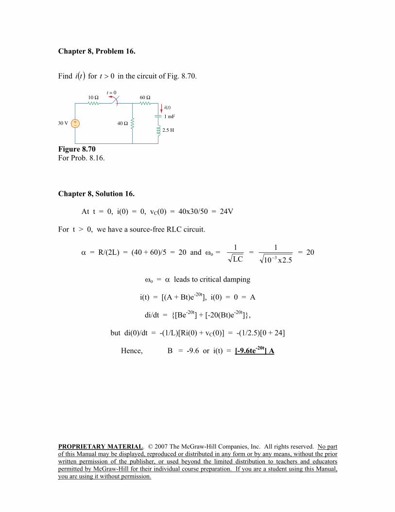
Chapter 8, Problem 16.
Find ti for 0t in the circuit of Fig. 8.70.
Figure 8.70
For Prob. 8.16.
Chapter 8, Solution 16.
At t = 0, i(0) = 0, vC(0) = 40x30/50 = 24V
For t > 0, we have a source-free RLC circuit.
= R/(2L) = (40 + 60)/5 = 20 and o =LC
1 =
5.2x10
1
3 = 20
o = leads to critical damping
i(t) = [(A + Bt)e-20t
], i(0) = 0 = A
di/dt = [Be-20t
] + [-20(Bt)e-20t
],
but di(0)/dt = -(1/L)[Ri(0) + vC(0)] = -(1/2.5)[0 + 24]
Hence, B = -9.6 or i(t) = [-9.6te-20t
] A
PROPRIETARY MATERIAL. © 2007 The McGraw-Hill Companies, Inc. All rights reserved. No part
of this Manual may be displayed, reproduced or distributed in any form or by any means, without the prior
written permission of the publisher, or used beyond the limited distribution to teachers and educators
permitted by McGraw-Hill for their individual course preparation. If you are a student using this Manual,
you are using it without permission.
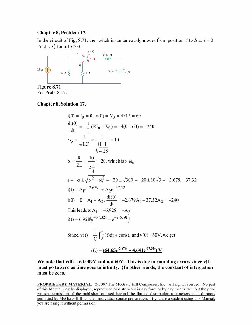
Chapter 8, Problem 17.
In the circuit of Fig. 8.71, the switch instantaneously moves from position A to B at 0t
Find tv for all 0t
Figure 8.71
For Prob. 8.17.
Chapter 8, Solution 17.
.iswhich,20
4
12
10
L2
R
10
25
1
4
1
1
LC
1
240)600(4)VRI(L
1
dt
)0(di
6015x4V)0(v,0I)0(i
o
o
00
00
t679.2t32.37
21
2121
t32.372
t679.21
2o
2
ee928.6)t(i
A928.6AtoleadsThis
240A32.37A679.2dt
)0(di,AA0)0(i
eAeA)t(i
32.37,679.23102030020s
getwe,V60)0(vand,constdt)t(iC
1)t(v,Since
t
0
v(t) = (64.65e-2.679t
– 4.641e-37.32t
) V
We note that v(0) = 60.009V and not 60V. This is due to rounding errors since v(t)
must go to zero as time goes to infinity. In other words, the constant of integration
must be zero.

PROPRIETARY MATERIAL. © 2007 The McGraw-Hill Companies, Inc. All rights reserved. No part
of this Manual may be displayed, reproduced or distributed in any form or by any means, without the prior
written permission of the publisher, or used beyond the limited distribution to teachers and educators
permitted by McGraw-Hill for their individual course preparation. If you are a student using this Manual,
you are using it without permission.
Chapter 8, Problem 18.
Find the voltage across the capacitor as a function of time for 0t for the circuit in Fig.
8.72. Assume steady-state conditions exist at 0t
Figure 8.72
For Prob. 8.18.
Chapter 8, Solution 18.
When the switch is off, we have a source-free parallel RLC circuit.
5.02
1,2
125.0
11
RCxLCo
936.125.04casedunderdampe 22
d oo
Io(0) = i(0) = initial inductor current = 20/5 = 4A
Vo(0) = v(0) = initial capacitor voltage = 0 V
)936.1sin936.1cos()sincos()( 21
5.0
21 tAtAetAtAetvt
dd
t
v(0) =0 = A1
)936.1cos936.1936.1sin936.1()936.1sin936.1cos)(5.0( 21
5.0
21
5.0tAtAetAtAe
dt
dv tt
066.2936.15.041
)40()()0(221 AAA
RC
RIV
dt
dvoo
Thus,
tetvt 936.1sin066.2)( 5.0
PROPRIETARY MATERIAL. © 2007 The McGraw-Hill Companies, Inc. All rights reserved. No part
of this Manual may be displayed, reproduced or distributed in any form or by any means, without the prior
written permission of the publisher, or used beyond the limited distribution to teachers and educators
permitted by McGraw-Hill for their individual course preparation. If you are a student using this Manual,
you are using it without permission.
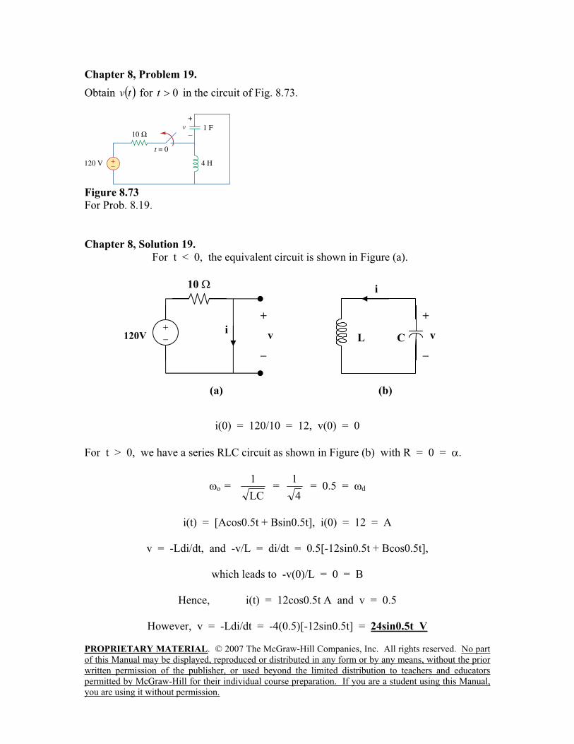
Chapter 8, Problem 19.
Obtain tv for 0t in the circuit of Fig. 8.73.
Figure 8.73
For Prob. 8.19.
Chapter 8, Solution 19.
For t < 0, the equivalent circuit is shown in Figure (a).
i(0) = 120/10 = 12, v(0) = 0
For t > 0, we have a series RLC circuit as shown in Figure (b) with R = 0 = .
o =LC
1 =
4
1 = 0.5 = d
i(t) = [Acos0.5t + Bsin0.5t], i(0) = 12 = A
v = -Ldi/dt, and -v/L = di/dt = 0.5[-12sin0.5t + Bcos0.5t],
which leads to -v(0)/L = 0 = B
Hence, i(t) = 12cos0.5t A and v = 0.5
However, v = -Ldi/dt = -4(0.5)[-12sin0.5t] = 24sin0.5t V
10
(a)
i
+
v120V+
L C
(b)
+
v
i
PROPRIETARY MATERIAL. © 2007 The McGraw-Hill Companies, Inc. All rights reserved. No part
of this Manual may be displayed, reproduced or distributed in any form or by any means, without the prior
written permission of the publisher, or used beyond the limited distribution to teachers and educators
permitted by McGraw-Hill for their individual course preparation. If you are a student using this Manual,
you are using it without permission.
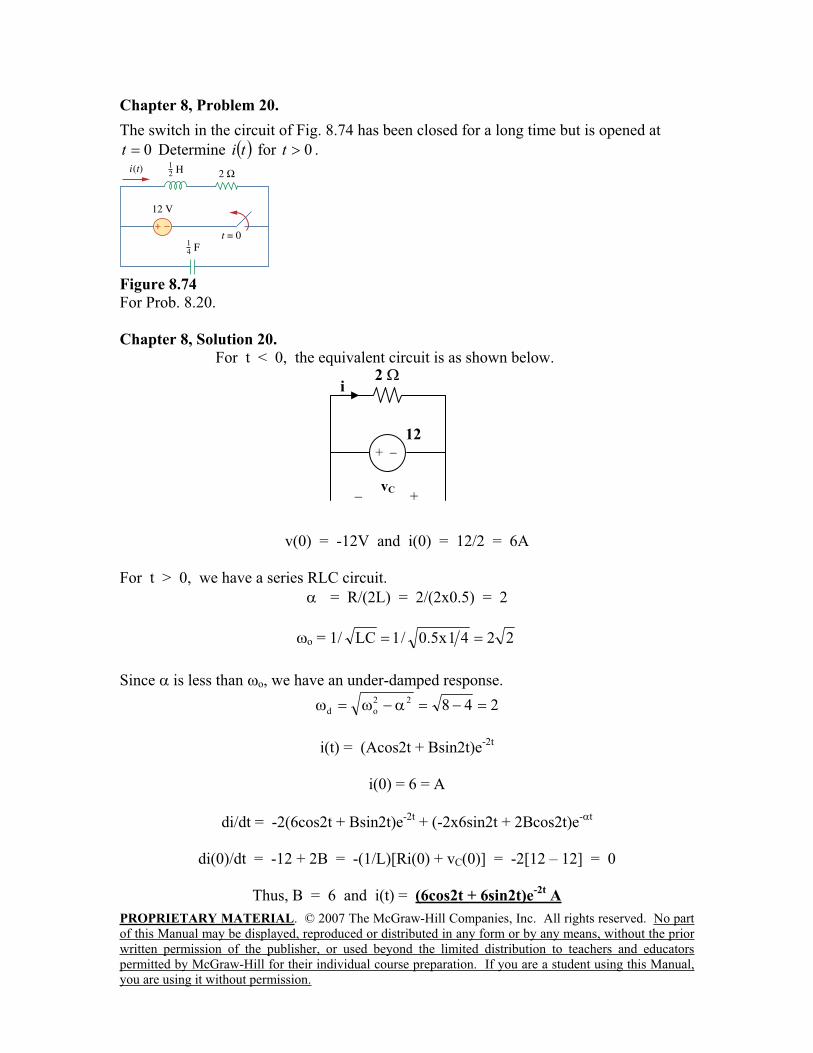
Chapter 8, Problem 20.
The switch in the circuit of Fig. 8.74 has been closed for a long time but is opened at
0t Determine ti for 0t .
Figure 8.74
For Prob. 8.20.
Chapter 8, Solution 20.
For t < 0, the equivalent circuit is as shown below.
v(0) = -12V and i(0) = 12/2 = 6A
For t > 0, we have a series RLC circuit.
= R/(2L) = 2/(2x0.5) = 2
o = 1/ 2241x5.0/1LC
Since is less than o, we have an under-damped response.
24822
od
i(t) = (Acos2t + Bsin2t)e-2t
i(0) = 6 = A
di/dt = -2(6cos2t + Bsin2t)e-2t
+ (-2x6sin2t + 2Bcos2t)e- t
di(0)/dt = -12 + 2B = -(1/L)[Ri(0) + vC(0)] = -2[12 – 12] = 0
Thus, B = 6 and i(t) = (6cos2t + 6sin2t)e-2t
A
2
+
12
+vC
i
PROPRIETARY MATERIAL. © 2007 The McGraw-Hill Companies, Inc. All rights reserved. No part
of this Manual may be displayed, reproduced or distributed in any form or by any means, without the prior
written permission of the publisher, or used beyond the limited distribution to teachers and educators
permitted by McGraw-Hill for their individual course preparation. If you are a student using this Manual,
you are using it without permission.
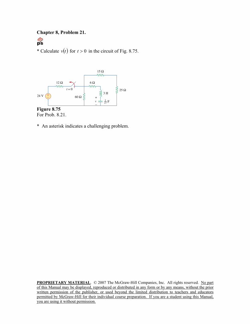
Chapter 8, Problem 21.
* Calculate tv for 0t in the circuit of Fig. 8.75.
Figure 8.75
For Prob. 8.21.
* An asterisk indicates a challenging problem.

PROPRIETARY MATERIAL. © 2007 The McGraw-Hill Companies, Inc. All rights reserved. No part
of this Manual may be displayed, reproduced or distributed in any form or by any means, without the prior
written permission of the publisher, or used beyond the limited distribution to teachers and educators
permitted by McGraw-Hill for their individual course preparation. If you are a student using this Manual,
you are using it without permission.
Chapter 8, Solution 21.
By combining some resistors, the circuit is equivalent to that shown below.
60||(15 + 25) = 24 ohms.
At t = 0-, i(0) = 0, v(0) = 24x24/36 = 16V
For t > 0, we have a series RLC circuit. R = 30 ohms, L = 3 H, C = (1/27) F
= R/(2L) = 30/6 = 5
27/1x3/1LC/1o = 3, clearly > o (overdamped response)
s1,2 =222
o
2 355 = -9, -1
v(t) = [Ae-t + Be
-9t], v(0) = 16 = A + B (1)
i = Cdv/dt = C[-Ae-t - 9Be
-9t]
i(0) = 0 = C[-A – 9B] or A = -9B (2)
From (1) and (2), B = -2 and A = 18.
Hence, v(t) = (18e-t – 2e
-9t) V
6
24
it = 0
+
v
3 H
(1/27)F
24V+
12
PROPRIETARY MATERIAL. © 2007 The McGraw-Hill Companies, Inc. All rights reserved. No part
of this Manual may be displayed, reproduced or distributed in any form or by any means, without the prior
written permission of the publisher, or used beyond the limited distribution to teachers and educators
permitted by McGraw-Hill for their individual course preparation. If you are a student using this Manual,
you are using it without permission.
Chapter 8, Problem 22.
Assuming k2R , design a parallel RLC circuit that has the characteristic equation
010100 62ss .
Chapter 8, Solution 22.
Compare the characteristic equation with eq. (8.8), i.e.
2 10
Rs s
L LCwe obtain
2000100 20
100 100
R RL H
L
66
6
1 1 1010 50 nF
2010C
LC L
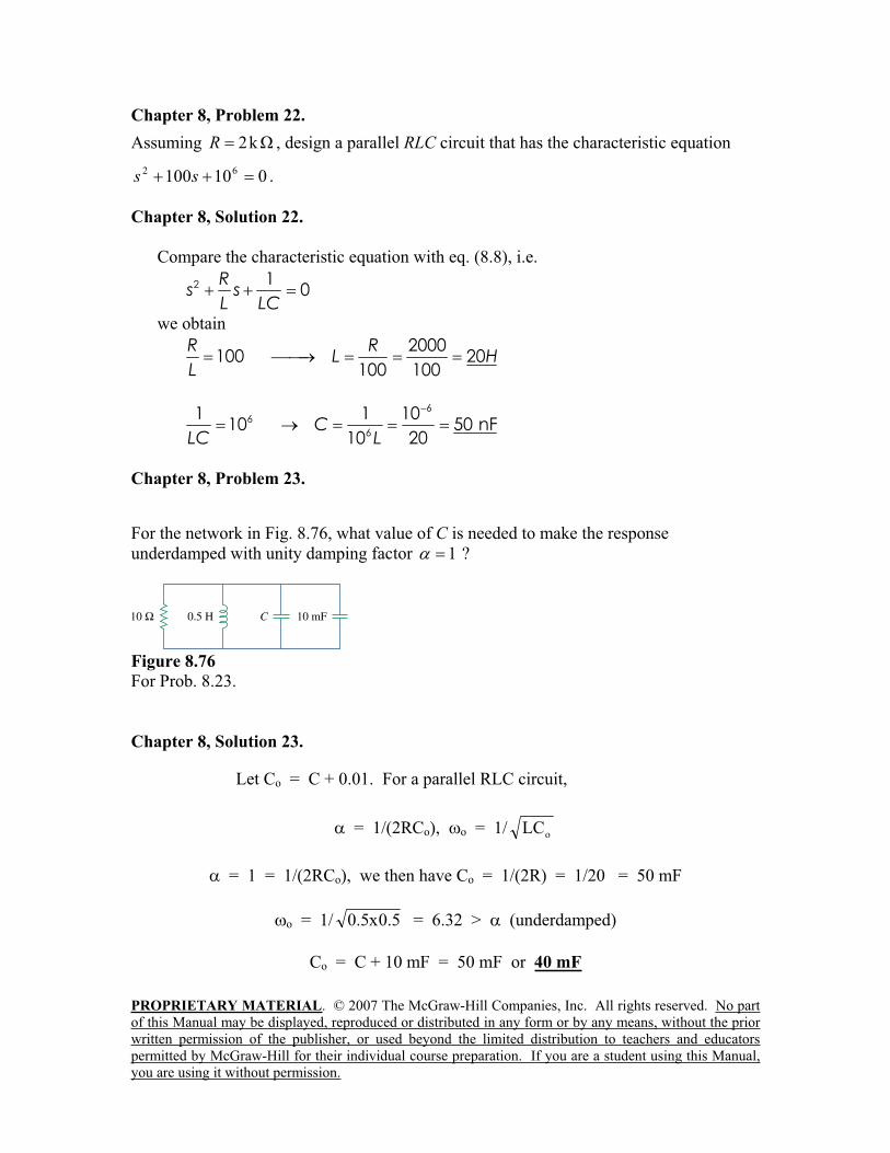
Chapter 8, Problem 23.
For the network in Fig. 8.76, what value of C is needed to make the response
underdamped with unity damping factor 1 ?
Figure 8.76
For Prob. 8.23.
Chapter 8, Solution 23.
Let Co = C + 0.01. For a parallel RLC circuit,
= 1/(2RCo), o = 1/ oLC
= 1 = 1/(2RCo), we then have Co = 1/(2R) = 1/20 = 50 mF
o = 1/ 5.0x5.0 = 6.32 > (underdamped)
Co = C + 10 mF = 50 mF or 40 mF
PROPRIETARY MATERIAL. © 2007 The McGraw-Hill Companies, Inc. All rights reserved. No part
of this Manual may be displayed, reproduced or distributed in any form or by any means, without the prior
written permission of the publisher, or used beyond the limited distribution to teachers and educators
permitted by McGraw-Hill for their individual course preparation. If you are a student using this Manual,
you are using it without permission.
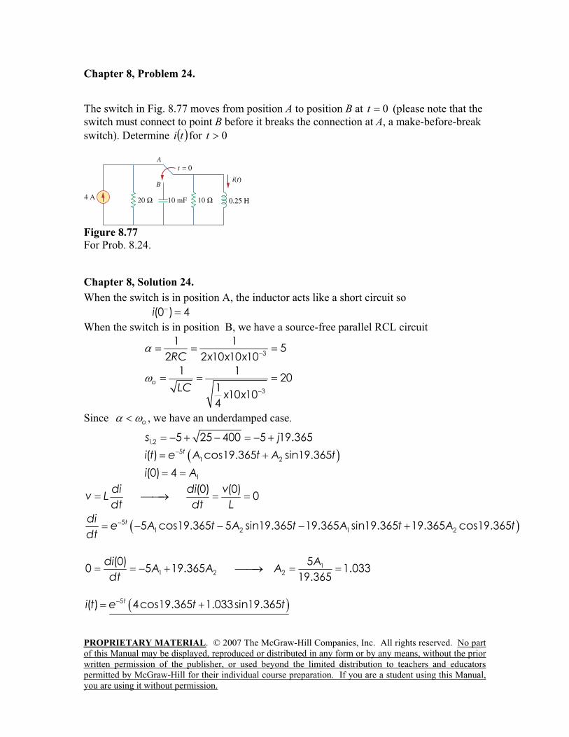
Chapter 8, Problem 24.
The switch in Fig. 8.77 moves from position A to position B at 0t (please note that the
switch must connect to point B before it breaks the connection at A, a make-before-break
switch). Determine ti for 0t
Figure 8.77
For Prob. 8.24.
Chapter 8, Solution 24.
When the switch is in position A, the inductor acts like a short circuit so
(0 ) 4i
When the switch is in position B, we have a source-free parallel RCL circuit
3
1 15
2 2 10 10 10RC x x x
3
1 120
110 10
4
oLC
x x
Since o , we have an underdamped case.
1,2 5 25 400 5 19.365s j5
1 2( ) cos19.365 sin19.365ti t e A t A t
1(0) 4i A
(0) (0)0
di di vv L
dt dt L
51 2 1 25 cos19.365 5 sin19.365 19.365 sin19.365 19.365 cos19.365tdi
e A t A t A t A tdt
11 2 2
(0) 50 5 19.365 1.033
19.365
di AA A A
dt
5( ) 4cos19.365 1.033sin19.365ti t e t t
PROPRIETARY MATERIAL. © 2007 The McGraw-Hill Companies, Inc. All rights reserved. No part
of this Manual may be displayed, reproduced or distributed in any form or by any means, without the prior
written permission of the publisher, or used beyond the limited distribution to teachers and educators
permitted by McGraw-Hill for their individual course preparation. If you are a student using this Manual,
you are using it without permission.
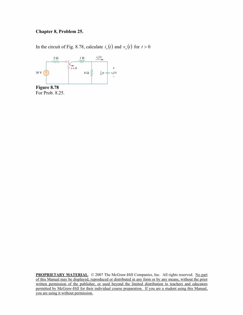
Chapter 8, Problem 25.
In the circuit of Fig. 8.78, calculate tio
and tvo
for 0t
Figure 8.78
For Prob. 8.25.

PROPRIETARY MATERIAL. © 2007 The McGraw-Hill Companies, Inc. All rights reserved. No part
of this Manual may be displayed, reproduced or distributed in any form or by any means, without the prior
written permission of the publisher, or used beyond the limited distribution to teachers and educators
permitted by McGraw-Hill for their individual course preparation. If you are a student using this Manual,
you are using it without permission.
Chapter 8, Solution 25.
In the circuit in Fig. 8.76, calculate io(t) and vo(t) for t>0.
Figure 8.78 For Problem 8.25.
At t = 0-, vo(0) = (8/(2 + 8)(30) = 24
For t > 0, we have a source-free parallel RLC circuit.
= 1/(2RC) = ¼
o = 1/ 241x1/1LC
Since is less than o, we have an under-damped response.
9843.1)16/1(422
od
vo(t) = (A1cos dt + A2sin dt)e- t
vo(0) = 30(8/(2+8)) = 24 = A1 and io(t) = C(dvo/dt) = 0 when t = 0.
dvo/dt = - (A1cos dt + A2sin dt)e- t
+ (- dA1sin dt + dA2cos dt)e- t
at t = 0, we get dvo(0)/dt = 0 = - A1 + dA2
Thus, A2 = ( / d)A1 = (1/4)(24)/1.9843 = 3.024
vo(t) = (24cos1.9843t + 3.024sin1.9843t)e-t/4
volts.
i0(t) = Cdv/dt = 0.25[–24(1.9843)sin1.9843t + 3.024(1.9843)cos1.9843t –
0.25(24cos1.9843t) – 0.25(3.024sin1.9843t)]e–t/4
= [0.000131cos1.9843t – 12.095sin1.9843t]e–t/4
A.
2
830V+
t=0, note this is a
make before break
switch so the
inductor current is
not interrupted.
+
vo(t)
1 H
(1/4)F
io(t)
PROPRIETARY MATERIAL. © 2007 The McGraw-Hill Companies, Inc. All rights reserved. No part
of this Manual may be displayed, reproduced or distributed in any form or by any means, without the prior
written permission of the publisher, or used beyond the limited distribution to teachers and educators
permitted by McGraw-Hill for their individual course preparation. If you are a student using this Manual,
you are using it without permission.
Chapter 8, Problem 26.
The step response of an RLC circuit is described by
10522
2
idt
di
dt
id
Given that 20i and 4/0 dtdi , solve for ti
Chapter 8, Solution 26.
s2 + 2s + 5 = 0, which leads to s1,2 =
2
2042 = -1 j4
i(t) = Is + [(A1cos4t + A2sin4t)e-t], Is = 10/5 = 2
i(0) = 2 = = 2 + A1, or A1 = 0
di/dt = [(A2cos4t)e-t] + [(-A2sin4t)e
-t] = 4 = 4A2, or A2 = 1
i(t) = 2 + sin4te-t A
Chapter 8, Problem 27.
A branch voltage in an RLC circuit is described by
24842
2
vdt
dv
dt
vd
If the initial conditions are dtdvv /000 , find tv .
Chapter 8, Solution 27.
s2 + 4s + 8 = 0 leads to s = 2j2
2
32164
v(t) = Vs + (A1cos2t + A2sin2t)e-2t
8Vs = 24 means that Vs = 3
v(0) = 0 = 3 + A1 leads to A1 = -3
dv/dt = -2(A1cos2t + A2sin2t)e-2t
+ (-2A1sin2t + 2A2cos2t)e-2t
0 = dv(0)/dt = -2A1 +2A2 or A2 = A1 = -3
v(t) = [3 – 3(cos2t + sin2t)e-2t
] volts
PROPRIETARY MATERIAL. © 2007 The McGraw-Hill Companies, Inc. All rights reserved. No part
of this Manual may be displayed, reproduced or distributed in any form or by any means, without the prior
written permission of the publisher, or used beyond the limited distribution to teachers and educators
permitted by McGraw-Hill for their individual course preparation. If you are a student using this Manual,
you are using it without permission.
Chapter 8, Problem 28.
A series RLC circuit is described by
22
2
C
i
dt
diR
dt
idL
Find the response when 4,5.0 RL ,
and 2.0C F. Let 0/0,10 dtdii .
Chapter 8, Solution 28.
The characteristic equation is
2 2 21 1 10 4 0 8 10 0
2 0.2Ls Rs s s s s
C
1,2
8 64 400.838, 7.162
2s
t5505.1t45.6s BeAei)t(i
But2
2 200.5 0.2
ss
II
LC x
t5505.1t45.6 BeAe20)t(i
i(0) = 1 = 20 + A + B or A + B = –19 (1)
B5505.1A45.60dt
)0(dibut
e5505.1Ae45.6dt
)t(di t5505.1t45.6
(2)
Solving (1) and (2) gives A= 6.013, B= –25.013
Hence,
i(t) = 20 + 6.013e–6.45t
–25.013e–1.5505t
A.
–6.45 and –1.5505
PROPRIETARY MATERIAL. © 2007 The McGraw-Hill Companies, Inc. All rights reserved. No part
of this Manual may be displayed, reproduced or distributed in any form or by any means, without the prior
written permission of the publisher, or used beyond the limited distribution to teachers and educators
permitted by McGraw-Hill for their individual course preparation. If you are a student using this Manual,
you are using it without permission.
Chapter 8, Problem 29.
Solve the following differential equations subject to the specified initial conditions
(a) 2/0,00,124/ 22dtdvvvdtvd
(b) 0/0,10,84/5/ 22dtdiiidtdidtid
(c) 1/0,50,3/2/ 22dtdvvvdtdvdtvd
(d) 2/0,40,105/2/ 22dtdiiidtdidtid
Chapter 8, Solution 29.
(a) s2 + 4 = 0 which leads to s1,2 = j2 (an undamped circuit)
v(t) = Vs + Acos2t + Bsin2t
4Vs = 12 or Vs = 3
v(0) = 0 = 3 + A or A = -3
dv/dt = -2Asin2t + 2Bcos2t
dv(0)/dt = 2 = 2B or B = 1, therefore v(t) = (3 – 3cos2t + sin2t) V
(b) s2 + 5s + 4 = 0 which leads to s1,2 = -1, -4
i(t) = (Is + Ae-t + Be
-4t)
4Is = 8 or Is = 2
i(0) = -1 = 2 + A + B, or A + B = -3 (1)
di/dt = -Ae-t - 4Be
-4t
di(0)/dt = 0 = -A – 4B, or B = -A/4 (2)
From (1) and (2) we get A = -4 and B = 1
i(t) = (2 – 4e-t + e
-4t) A
PROPRIETARY MATERIAL. © 2007 The McGraw-Hill Companies, Inc. All rights reserved. No part
of this Manual may be displayed, reproduced or distributed in any form or by any means, without the prior
written permission of the publisher, or used beyond the limited distribution to teachers and educators
permitted by McGraw-Hill for their individual course preparation. If you are a student using this Manual,
you are using it without permission.
(c) s2 + 2s + 1 = 0, s1,2 = -1, -1
v(t) = [Vs + (A + Bt)e-t], Vs = 3.
v(0) = 5 = 3 + A or A = 2
dv/dt = [-(A + Bt)e-t] + [Be
-t]
dv(0)/dt = -A + B = 1 or B = 2 + 1 = 3
v(t) = [3 + (2 + 3t)e-t] V
(d) s2 + 2s +5 = 0, s1,2 = -1 + j2, -1 – j2
i(t) = [Is + (Acos2t + Bsin2t)e-t], where 5Is = 10 or Is = 2
i(0) = 4 = 2 + A or A = 2
di/dt = [-(Acos2t + Bsin2t)e-t] + [(-2Asin2t + 2Bcos2t)e
-t]
di(0)/dt = -2 = -A + 2B or B = 0
i(t) = [2 + (2cos2t)e-t] A
PROPRIETARY MATERIAL. © 2007 The McGraw-Hill Companies, Inc. All rights reserved. No part
of this Manual may be displayed, reproduced or distributed in any form or by any means, without the prior
written permission of the publisher, or used beyond the limited distribution to teachers and educators
permitted by McGraw-Hill for their individual course preparation. If you are a student using this Manual,
you are using it without permission.
Chapter 8, Problem 30.
The step responses of a series RLC circuit are tt
Ceev
40002000 101040 V, 0t
tt
Leeti
40002000 63 mA, 0t
(a) Find C. (b) Determine what type of damping is exhibited by the circuit.
Chapter 8, Solution 30.
(a) ( ) ( ) oL C
dvi t i t C
dt (1)
2000 4000 4 2000 40002000 10 4000 10 2 10 ( 2 )t t t tdvx e x e x e e
dt (2)
But 2000 4000 -3( ) 3[ 2 ]x10t t
Li t e e (3)
Substituting (2) and (3) into (1), we get
4 3 72 10 3 10 1.5 10 150 nFx xC x C x
(b) Since s1 = - 2000 and s2 = - 4000 are real and negative, it is an overdamped case.

PROPRIETARY MATERIAL. © 2007 The McGraw-Hill Companies, Inc. All rights reserved. No part
of this Manual may be displayed, reproduced or distributed in any form or by any means, without the prior
written permission of the publisher, or used beyond the limited distribution to teachers and educators
permitted by McGraw-Hill for their individual course preparation. If you are a student using this Manual,
you are using it without permission.
Chapter 8, Problem 31.
Consider the circuit in Fig. 8.79. Find 0Lv and 0
Cv
Figure 8.79
For Prob. 8.31.
Chapter 8, Solution 31.
For t = 0-, we have the equivalent circuit in Figure (a). For t = 0+, the equivalent
circuit is shown in Figure (b). By KVL,
v(0+) = v(0-) = 40, i(0+) = i(0-) = 1
By KCL, 2 = i(0+) + i1 = 1 + i1 which leads to i1 = 1. By KVL, -vL + 40i1 + v(0+)
= 0 which leads to vL(0+) = 40x1 + 40 = 80
vL(0+) = 80 V, vC(0+) = 40 V
i
40
(a)
+
v 50V+
10 i1
0.5H
40
(b)
+
v 50V+
10
+
vL
PROPRIETARY MATERIAL. © 2007 The McGraw-Hill Companies, Inc. All rights reserved. No part
of this Manual may be displayed, reproduced or distributed in any form or by any means, without the prior
written permission of the publisher, or used beyond the limited distribution to teachers and educators
permitted by McGraw-Hill for their individual course preparation. If you are a student using this Manual,
you are using it without permission.
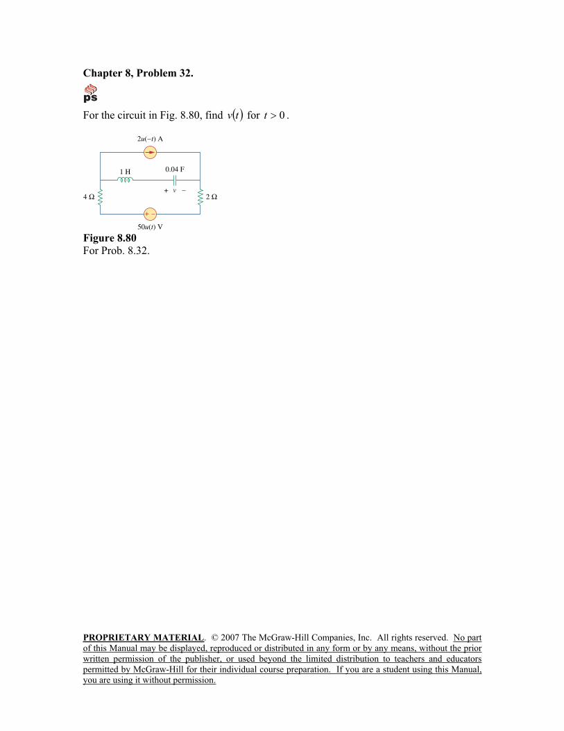
Chapter 8, Problem 32.
For the circuit in Fig. 8.80, find tv for 0t .
Figure 8.80
For Prob. 8.32.
PROPRIETARY MATERIAL. © 2007 The McGraw-Hill Companies, Inc. All rights reserved. No part
of this Manual may be displayed, reproduced or distributed in any form or by any means, without the prior
written permission of the publisher, or used beyond the limited distribution to teachers and educators
permitted by McGraw-Hill for their individual course preparation. If you are a student using this Manual,
you are using it without permission.
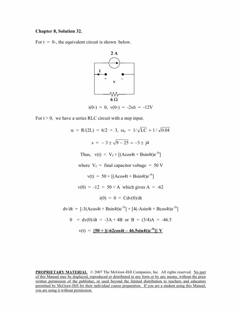
Chapter 8, Solution 32.
For t = 0-, the equivalent circuit is shown below.
i(0-) = 0, v(0-) = -2x6 = -12V
For t > 0, we have a series RLC circuit with a step input.
= R/(2L) = 6/2 = 3, o = 1/ 04.0/1LC
s = 4j32593
Thus, v(t) = Vf + [(Acos4t + Bsin4t)e-3t
]
where Vf = final capacitor voltage = 50 V
v(t) = 50 + [(Acos4t + Bsin4t)e-3t
]
v(0) = -12 = 50 + A which gives A = -62
i(0) = 0 = Cdv(0)/dt
dv/dt = [-3(Acos4t + Bsin4t)e-3t
] + [4(-Asin4t + Bcos4t)e-3t
]
0 = dv(0)/dt = -3A + 4B or B = (3/4)A = -46.5
v(t) = 50 + [(-62cos4t – 46.5sin4t)e-3t
] V
2 A
+ v
6
i
PROPRIETARY MATERIAL. © 2007 The McGraw-Hill Companies, Inc. All rights reserved. No part
of this Manual may be displayed, reproduced or distributed in any form or by any means, without the prior
written permission of the publisher, or used beyond the limited distribution to teachers and educators
permitted by McGraw-Hill for their individual course preparation. If you are a student using this Manual,
you are using it without permission.
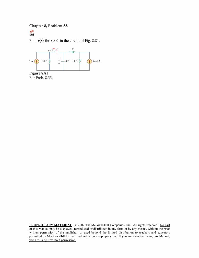
Chapter 8, Problem 33.
Find tv for 0t in the circuit of Fig. 8.81.
Figure 8.81
For Prob. 8.33.
PROPRIETARY MATERIAL. © 2007 The McGraw-Hill Companies, Inc. All rights reserved. No part
of this Manual may be displayed, reproduced or distributed in any form or by any means, without the prior
written permission of the publisher, or used beyond the limited distribution to teachers and educators
permitted by McGraw-Hill for their individual course preparation. If you are a student using this Manual,
you are using it without permission.
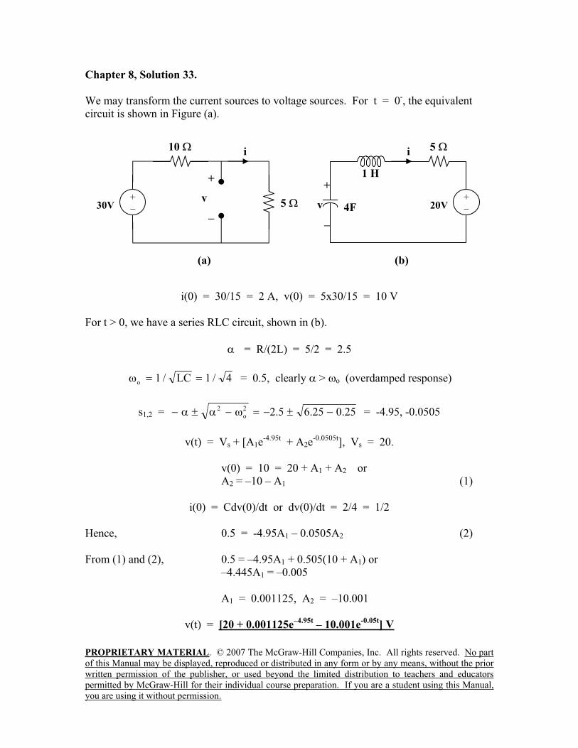
Chapter 8, Solution 33.
We may transform the current sources to voltage sources. For t = 0-, the equivalent
circuit is shown in Figure (a).
i(0) = 30/15 = 2 A, v(0) = 5x30/15 = 10 V
For t > 0, we have a series RLC circuit, shown in (b).
= R/(2L) = 5/2 = 2.5
4/1LC/1o = 0.5, clearly > o (overdamped response)
s1,2 = 25.025.65.22
o
2 = -4.95, -0.0505
v(t) = Vs + [A1e-4.95t
+ A2e-0.0505t
], Vs = 20.
v(0) = 10 = 20 + A1 + A2 or
A2 = –10 – A1 (1)
i(0) = Cdv(0)/dt or dv(0)/dt = 2/4 = 1/2
Hence, 0.5 = -4.95A1 – 0.0505A2 (2)
From (1) and (2), 0.5 = –4.95A1 + 0.505(10 + A1) or
–4.445A1 = –0.005
A1 = 0.001125, A2 = –10.001
v(t) = [20 + 0.001125e–4.95t
– 10.001e-0.05t
] V
(a)
+
v
10
530V+
i
4F
(b)
+
v 20V+
i
1 H
5
PROPRIETARY MATERIAL. © 2007 The McGraw-Hill Companies, Inc. All rights reserved. No part
of this Manual may be displayed, reproduced or distributed in any form or by any means, without the prior
written permission of the publisher, or used beyond the limited distribution to teachers and educators
permitted by McGraw-Hill for their individual course preparation. If you are a student using this Manual,
you are using it without permission.
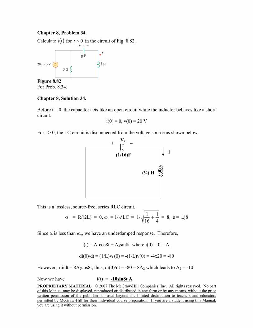
Chapter 8, Problem 34.
Calculate ti for 0t in the circuit of Fig. 8.82.
Figure 8.82
For Prob. 8.34.
Chapter 8, Solution 34.
Before t = 0, the capacitor acts like an open circuit while the inductor behaves like a short
circuit.
i(0) = 0, v(0) = 20 V
For t > 0, the LC circuit is disconnected from the voltage source as shown below.
This is a lossless, source-free, series RLC circuit.
= R/(2L) = 0, o = 1/ LC = 1/4
1
16
1 = 8, s = j8
Since is less than o, we have an underdamped response. Therefore,
i(t) = A1cos8t + A2sin8t where i(0) = 0 = A1
di(0)/dt = (1/L)vL(0) = -(1/L)v(0) = -4x20 = -80
However, di/dt = 8A2cos8t, thus, di(0)/dt = -80 = 8A2 which leads to A2 = -10
Now we have i(t) = -10sin8t A
(¼) H
(1/16)Fi
+Vx
PROPRIETARY MATERIAL. © 2007 The McGraw-Hill Companies, Inc. All rights reserved. No part
of this Manual may be displayed, reproduced or distributed in any form or by any means, without the prior
written permission of the publisher, or used beyond the limited distribution to teachers and educators
permitted by McGraw-Hill for their individual course preparation. If you are a student using this Manual,
you are using it without permission.
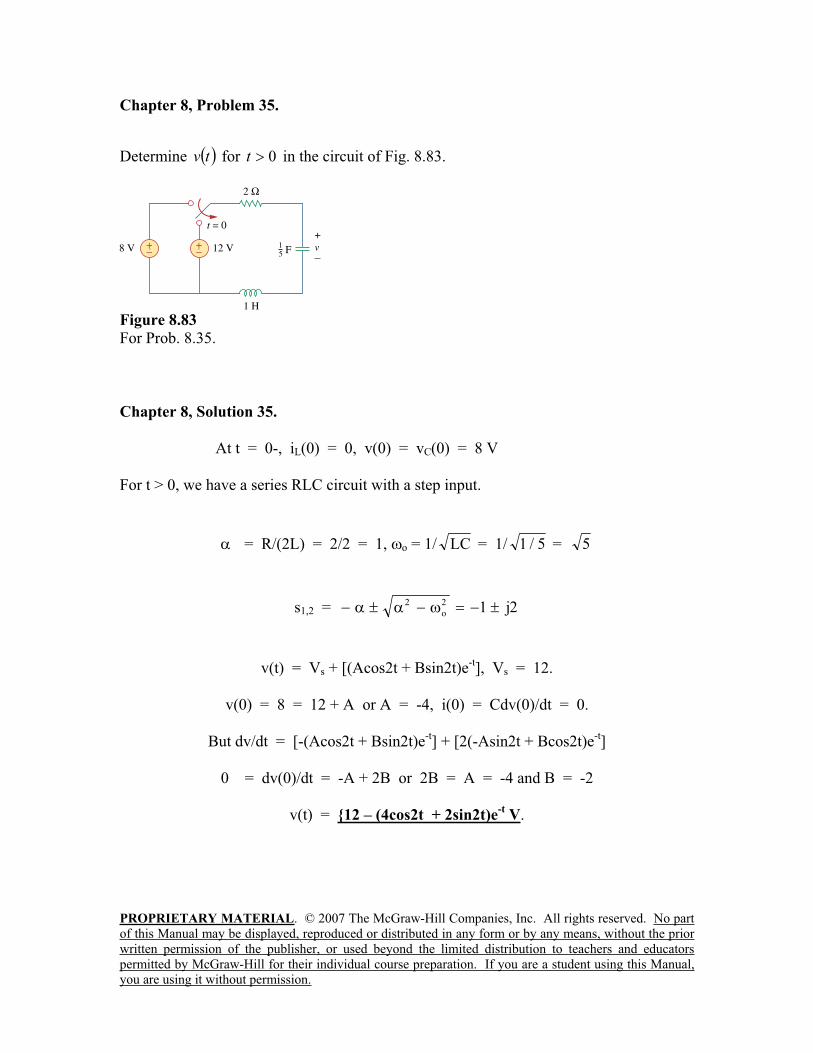
Chapter 8, Problem 35.
Determine tv for 0t in the circuit of Fig. 8.83.
Figure 8.83
For Prob. 8.35.
Chapter 8, Solution 35.
At t = 0-, iL(0) = 0, v(0) = vC(0) = 8 V
For t > 0, we have a series RLC circuit with a step input.
= R/(2L) = 2/2 = 1, o = 1/ LC = 1/ 5/1 = 5
s1,2 = 2j12
o
2
v(t) = Vs + [(Acos2t + Bsin2t)e-t], Vs = 12.
v(0) = 8 = 12 + A or A = -4, i(0) = Cdv(0)/dt = 0.
But dv/dt = [-(Acos2t + Bsin2t)e-t] + [2(-Asin2t + Bcos2t)e
-t]
0 = dv(0)/dt = -A + 2B or 2B = A = -4 and B = -2
v(t) = 12 – (4cos2t + 2sin2t)e-t V.
PROPRIETARY MATERIAL. © 2007 The McGraw-Hill Companies, Inc. All rights reserved. No part
of this Manual may be displayed, reproduced or distributed in any form or by any means, without the prior
written permission of the publisher, or used beyond the limited distribution to teachers and educators
permitted by McGraw-Hill for their individual course preparation. If you are a student using this Manual,
you are using it without permission.
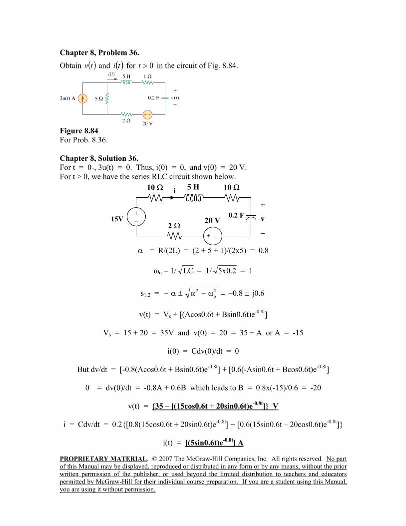
Chapter 8, Problem 36.
Obtain tv and ti for 0t in the circuit of Fig. 8.84.
Figure 8.84
For Prob. 8.36.
Chapter 8, Solution 36.
For t = 0-, 3u(t) = 0. Thus, i(0) = 0, and v(0) = 20 V.
For t > 0, we have the series RLC circuit shown below.
= R/(2L) = (2 + 5 + 1)/(2x5) = 0.8
o = 1/ LC = 1/ 2.0x5 = 1
s1,2 = 6.0j8.02
o
2
v(t) = Vs + [(Acos0.6t + Bsin0.6t)e-0.8t
]
Vs = 15 + 20 = 35V and v(0) = 20 = 35 + A or A = -15
i(0) = Cdv(0)/dt = 0
But dv/dt = [-0.8(Acos0.6t + Bsin0.6t)e-0.8t
] + [0.6(-Asin0.6t + Bcos0.6t)e-0.8t
]
0 = dv(0)/dt = -0.8A + 0.6B which leads to B = 0.8x(-15)/0.6 = -20
v(t) = 35 – [(15cos0.6t + 20sin0.6t)e-0.8t
] V
i = Cdv/dt = 0.2[0.8(15cos0.6t + 20sin0.6t)e-0.8t
] + [0.6(15sin0.6t – 20cos0.6t)e-0.8t
]
i(t) = [(5sin0.6t)e-0.8t
] A
15V+
+
10i
0.2 F
+
v
10
220 V
5 H
PROPRIETARY MATERIAL. © 2007 The McGraw-Hill Companies, Inc. All rights reserved. No part
of this Manual may be displayed, reproduced or distributed in any form or by any means, without the prior
written permission of the publisher, or used beyond the limited distribution to teachers and educators
permitted by McGraw-Hill for their individual course preparation. If you are a student using this Manual,
you are using it without permission.
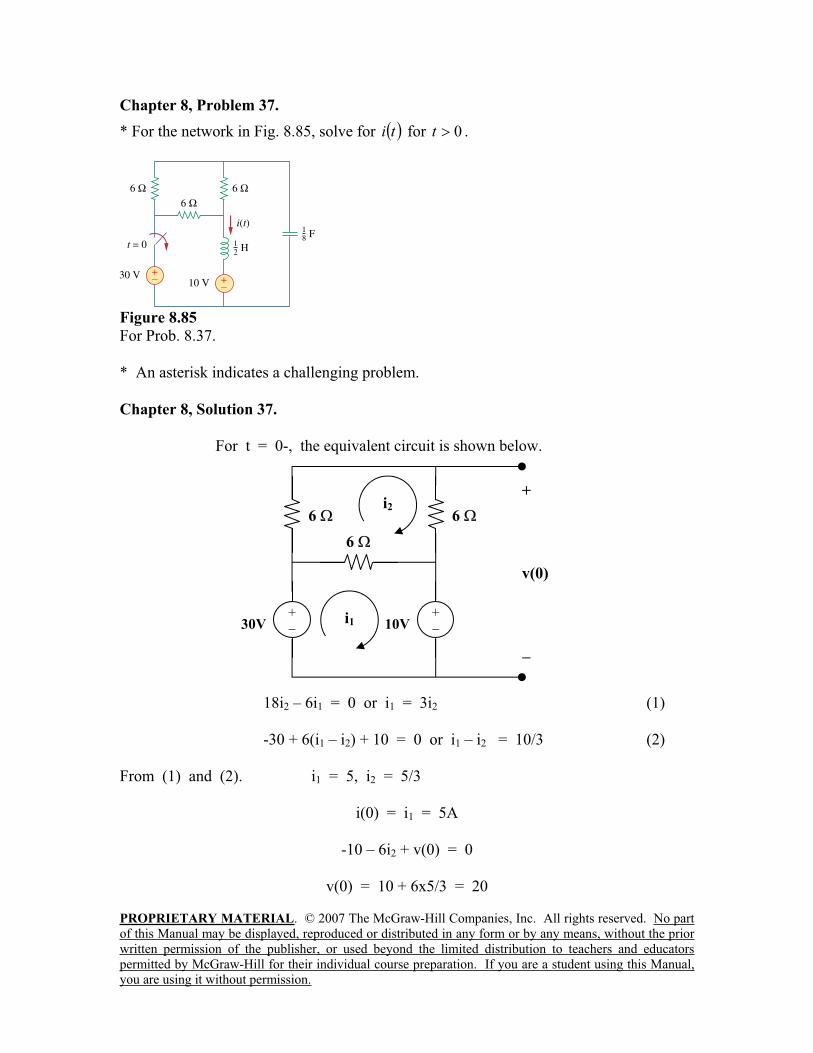
Chapter 8, Problem 37.
* For the network in Fig. 8.85, solve for ti for 0t .
Figure 8.85
For Prob. 8.37.
* An asterisk indicates a challenging problem.
Chapter 8, Solution 37.
For t = 0-, the equivalent circuit is shown below.
18i2 – 6i1 = 0 or i1 = 3i2 (1)
-30 + 6(i1 – i2) + 10 = 0 or i1 – i2 = 10/3 (2)
From (1) and (2). i1 = 5, i2 = 5/3
i(0) = i1 = 5A
-10 – 6i2 + v(0) = 0
v(0) = 10 + 6x5/3 = 20
6
6
+
v(0)
i1
i2
30V+
10V+
6
PROPRIETARY MATERIAL. © 2007 The McGraw-Hill Companies, Inc. All rights reserved. No part
of this Manual may be displayed, reproduced or distributed in any form or by any means, without the prior
written permission of the publisher, or used beyond the limited distribution to teachers and educators
permitted by McGraw-Hill for their individual course preparation. If you are a student using this Manual,
you are using it without permission.
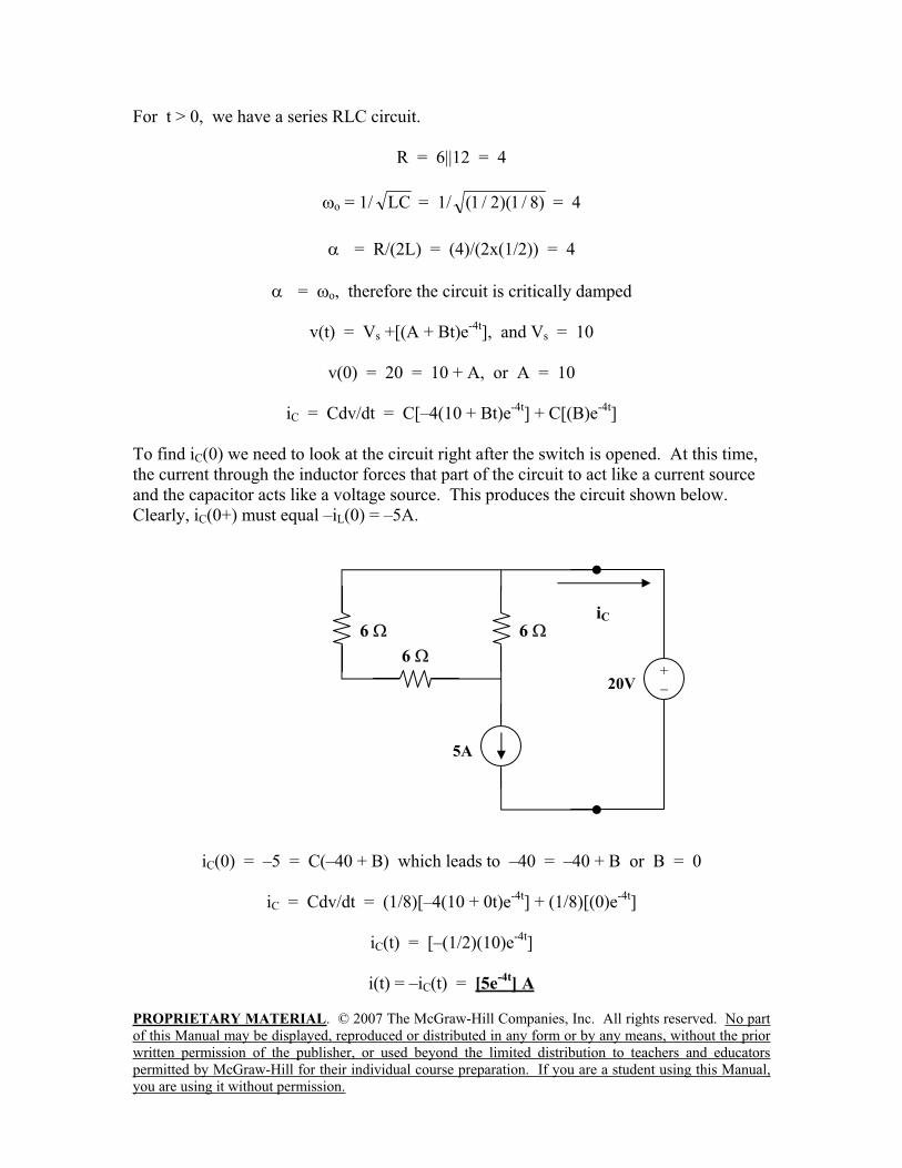
For t > 0, we have a series RLC circuit.
R = 6||12 = 4
o = 1/ LC = 1/ )8/1)(2/1( = 4
= R/(2L) = (4)/(2x(1/2)) = 4
= o, therefore the circuit is critically damped
v(t) = Vs +[(A + Bt)e-4t
], and Vs = 10
v(0) = 20 = 10 + A, or A = 10
iC = Cdv/dt = C[–4(10 + Bt)e-4t
] + C[(B)e-4t
]
To find iC(0) we need to look at the circuit right after the switch is opened. At this time,
the current through the inductor forces that part of the circuit to act like a current source
and the capacitor acts like a voltage source. This produces the circuit shown below.
Clearly, iC(0+) must equal –iL(0) = –5A.
iC(0) = –5 = C(–40 + B) which leads to –40 = –40 + B or B = 0
iC = Cdv/dt = (1/8)[–4(10 + 0t)e-4t
] + (1/8)[(0)e-4t
]
iC(t) = [–(1/2)(10)e-4t
]
i(t) = –iC(t) = [5e-4t
] A
6
6iC
5A
6
20V+
PROPRIETARY MATERIAL. © 2007 The McGraw-Hill Companies, Inc. All rights reserved. No part
of this Manual may be displayed, reproduced or distributed in any form or by any means, without the prior
written permission of the publisher, or used beyond the limited distribution to teachers and educators
permitted by McGraw-Hill for their individual course preparation. If you are a student using this Manual,
you are using it without permission.
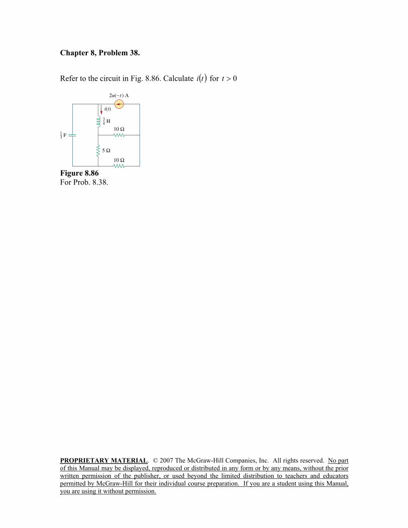
Chapter 8, Problem 38.
Refer to the circuit in Fig. 8.86. Calculate ti for 0t
Figure 8.86
For Prob. 8.38.
PROPRIETARY MATERIAL. © 2007 The McGraw-Hill Companies, Inc. All rights reserved. No part
of this Manual may be displayed, reproduced or distributed in any form or by any means, without the prior
written permission of the publisher, or used beyond the limited distribution to teachers and educators
permitted by McGraw-Hill for their individual course preparation. If you are a student using this Manual,
you are using it without permission.
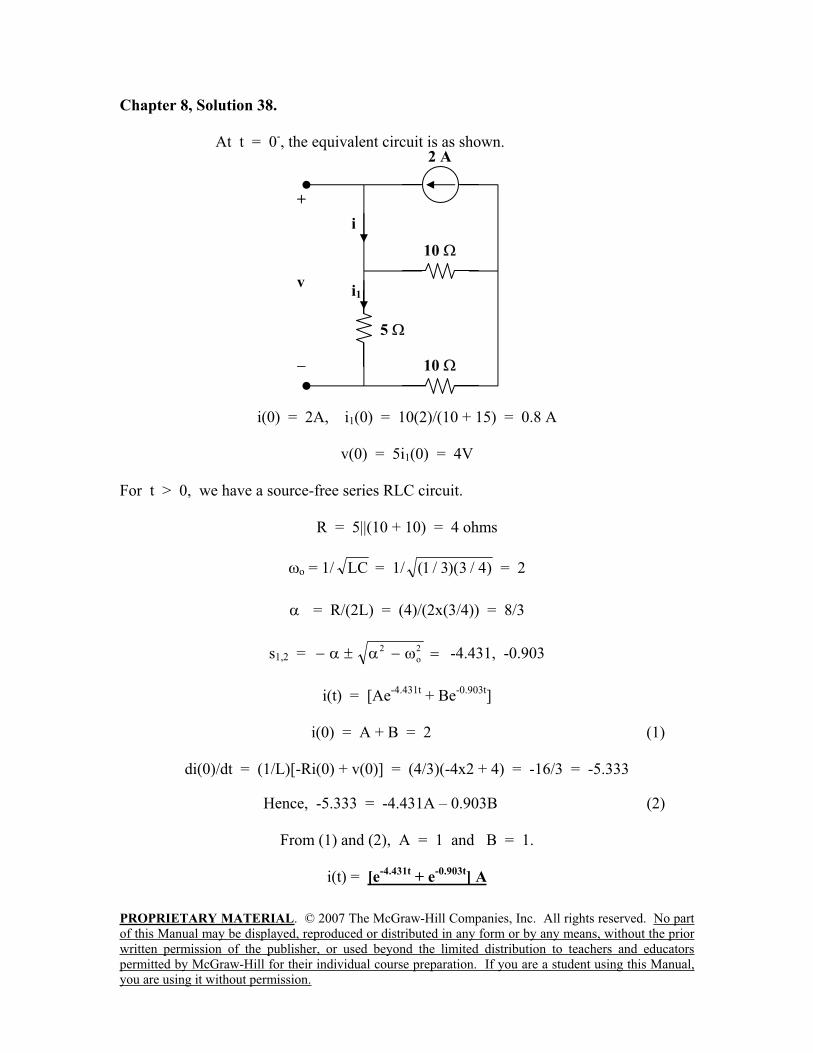
Chapter 8, Solution 38.
At t = 0-, the equivalent circuit is as shown.
i(0) = 2A, i1(0) = 10(2)/(10 + 15) = 0.8 A
v(0) = 5i1(0) = 4V
For t > 0, we have a source-free series RLC circuit.
R = 5||(10 + 10) = 4 ohms
o = 1/ LC = 1/ )4/3)(3/1( = 2
= R/(2L) = (4)/(2x(3/4)) = 8/3
s1,2 =2
o
2 -4.431, -0.903
i(t) = [Ae-4.431t
+ Be-0.903t
]
i(0) = A + B = 2 (1)
di(0)/dt = (1/L)[-Ri(0) + v(0)] = (4/3)(-4x2 + 4) = -16/3 = -5.333
Hence, -5.333 = -4.431A – 0.903B (2)
From (1) and (2), A = 1 and B = 1.
i(t) = [e-4.431t
+ e-0.903t
] A
10
+
v
5
i1
i
2 A
10
PROPRIETARY MATERIAL. © 2007 The McGraw-Hill Companies, Inc. All rights reserved. No part
of this Manual may be displayed, reproduced or distributed in any form or by any means, without the prior
written permission of the publisher, or used beyond the limited distribution to teachers and educators
permitted by McGraw-Hill for their individual course preparation. If you are a student using this Manual,
you are using it without permission.
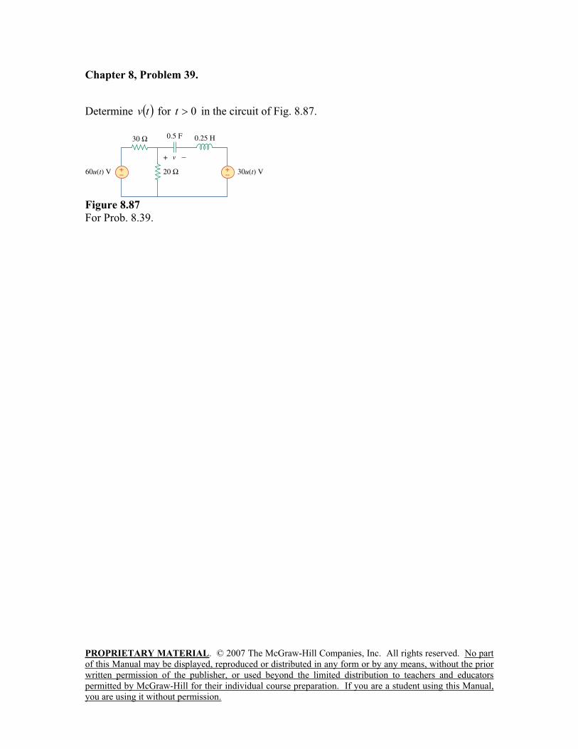
Chapter 8, Problem 39.
Determine tv for 0t in the circuit of Fig. 8.87.
Figure 8.87
For Prob. 8.39.
PROPRIETARY MATERIAL. © 2007 The McGraw-Hill Companies, Inc. All rights reserved. No part
of this Manual may be displayed, reproduced or distributed in any form or by any means, without the prior
written permission of the publisher, or used beyond the limited distribution to teachers and educators
permitted by McGraw-Hill for their individual course preparation. If you are a student using this Manual,
you are using it without permission.
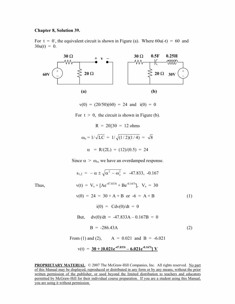
Chapter 8, Solution 39.
For t = 0-, the equivalent circuit is shown in Figure (a). Where 60u(-t) = 60 and
30u(t) = 0.
v(0) = (20/50)(60) = 24 and i(0) = 0
For t > 0, the circuit is shown in Figure (b).
R = 20||30 = 12 ohms
o = 1/ LC = 1/ )4/1)(2/1( = 8
= R/(2L) = (12)/(0.5) = 24
Since > o, we have an overdamped response.
s1,2 =2
o
2 -47.833, -0.167
Thus, v(t) = Vs + [Ae-47.833t
+ Be-0.167t
], Vs = 30
v(0) = 24 = 30 + A + B or -6 = A + B (1)
i(0) = Cdv(0)/dt = 0
But, dv(0)/dt = -47.833A – 0.167B = 0
B = -286.43A (2)
From (1) and (2), A = 0.021 and B = -6.021
v(t) = 30 + [0.021e-47.833t
– 6.021e-0.167t
] V
30
20
(a)
+ v
60V+
0.5F30
20
(b)
30V+
0.25H
PROPRIETARY MATERIAL. © 2007 The McGraw-Hill Companies, Inc. All rights reserved. No part
of this Manual may be displayed, reproduced or distributed in any form or by any means, without the prior
written permission of the publisher, or used beyond the limited distribution to teachers and educators
permitted by McGraw-Hill for their individual course preparation. If you are a student using this Manual,
you are using it without permission.
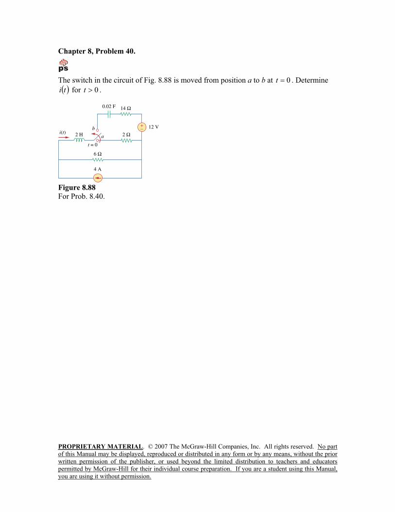
Chapter 8, Problem 40.
The switch in the circuit of Fig. 8.88 is moved from position a to b at 0t . Determine
ti for 0t .
Figure 8.88
For Prob. 8.40.
PROPRIETARY MATERIAL. © 2007 The McGraw-Hill Companies, Inc. All rights reserved. No part
of this Manual may be displayed, reproduced or distributed in any form or by any means, without the prior
written permission of the publisher, or used beyond the limited distribution to teachers and educators
permitted by McGraw-Hill for their individual course preparation. If you are a student using this Manual,
you are using it without permission.
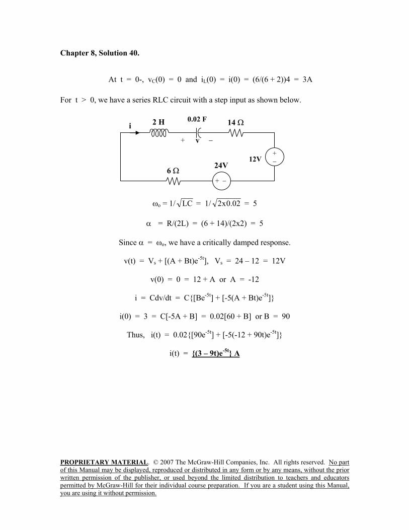
Chapter 8, Solution 40.
At t = 0-, vC(0) = 0 and iL(0) = i(0) = (6/(6 + 2))4 = 3A
For t > 0, we have a series RLC circuit with a step input as shown below.
o = 1/ LC = 1/ 02.0x2 = 5
= R/(2L) = (6 + 14)/(2x2) = 5
Since = o, we have a critically damped response.
v(t) = Vs + [(A + Bt)e-5t
], Vs = 24 – 12 = 12V
v(0) = 0 = 12 + A or A = -12
i = Cdv/dt = C[Be-5t
] + [-5(A + Bt)e-5t
]
i(0) = 3 = C[-5A + B] = 0.02[60 + B] or B = 90
Thus, i(t) = 0.02[90e-5t
] + [-5(-12 + 90t)e-5t
]
i(t) = (3 – 9t)e-5t
A
14i
24V
2 H 0.02 F
12V+
+
6
+ v
PROPRIETARY MATERIAL. © 2007 The McGraw-Hill Companies, Inc. All rights reserved. No part
of this Manual may be displayed, reproduced or distributed in any form or by any means, without the prior
written permission of the publisher, or used beyond the limited distribution to teachers and educators
permitted by McGraw-Hill for their individual course preparation. If you are a student using this Manual,
you are using it without permission.
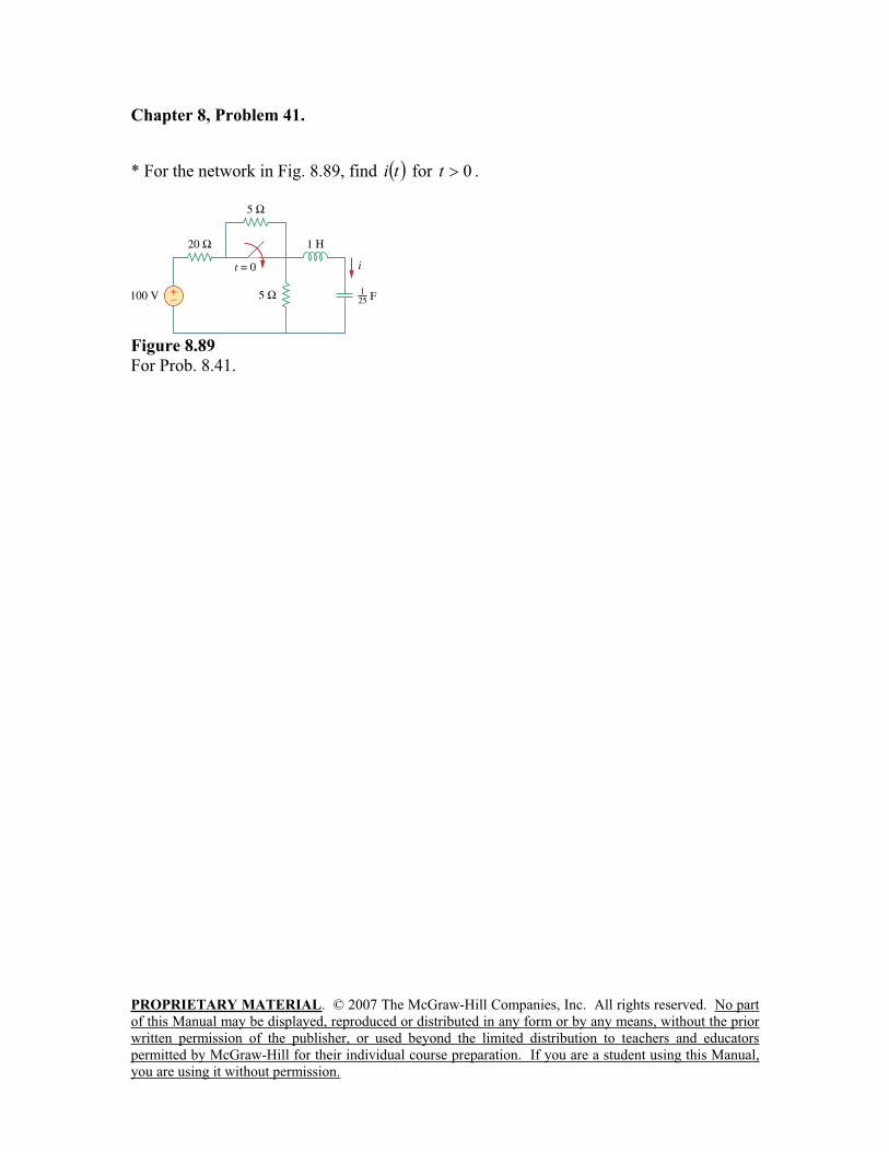
Chapter 8, Problem 41.
* For the network in Fig. 8.89, find ti for 0t .
Figure 8.89
For Prob. 8.41.
PROPRIETARY MATERIAL. © 2007 The McGraw-Hill Companies, Inc. All rights reserved. No part
of this Manual may be displayed, reproduced or distributed in any form or by any means, without the prior
written permission of the publisher, or used beyond the limited distribution to teachers and educators
permitted by McGraw-Hill for their individual course preparation. If you are a student using this Manual,
you are using it without permission.
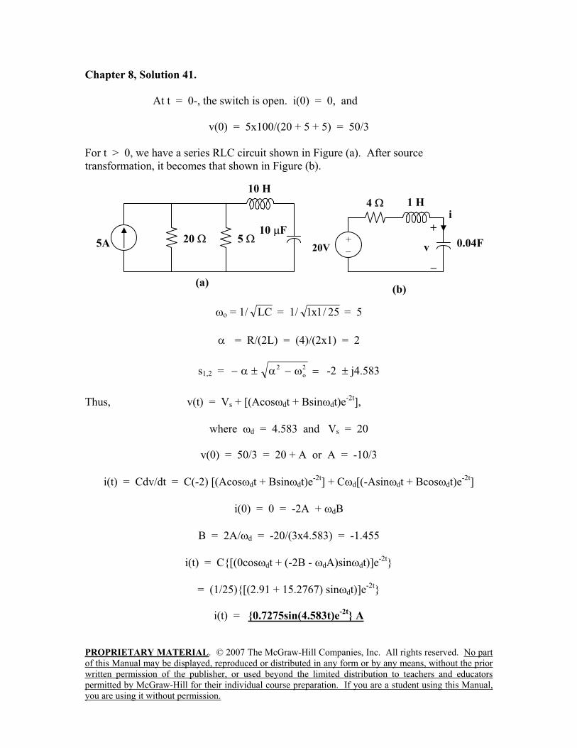
Chapter 8, Solution 41.
At t = 0-, the switch is open. i(0) = 0, and
v(0) = 5x100/(20 + 5 + 5) = 50/3
For t > 0, we have a series RLC circuit shown in Figure (a). After source
transformation, it becomes that shown in Figure (b).
o = 1/ LC = 1/ 25/1x1 = 5
= R/(2L) = (4)/(2x1) = 2
s1,2 =2
o
2 -2 j4.583
Thus, v(t) = Vs + [(Acos dt + Bsin dt)e-2t
],
where d = 4.583 and Vs = 20
v(0) = 50/3 = 20 + A or A = -10/3
i(t) = Cdv/dt = C(-2) [(Acos dt + Bsin dt)e-2t
] + C d[(-Asin dt + Bcos dt)e-2t
]
i(0) = 0 = -2A + dB
B = 2A/ d = -20/(3x4.583) = -1.455
i(t) = C[(0cos dt + (-2B - dA)sin dt)]e-2t
= (1/25)[(2.91 + 15.2767) sin dt)]e-2t
i(t) = 0.7275sin(4.583t)e-2t
A
5
(a)
5A
10 H
10 F20
4i
+
v20V+
(b)
1 H
0.04F
PROPRIETARY MATERIAL. © 2007 The McGraw-Hill Companies, Inc. All rights reserved. No part
of this Manual may be displayed, reproduced or distributed in any form or by any means, without the prior
written permission of the publisher, or used beyond the limited distribution to teachers and educators
permitted by McGraw-Hill for their individual course preparation. If you are a student using this Manual,
you are using it without permission.
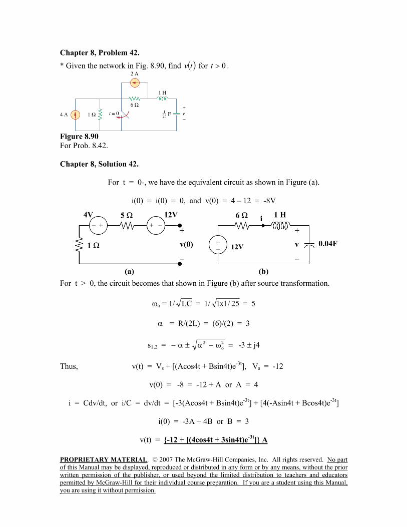
Chapter 8, Problem 42.
* Given the network in Fig. 8.90, find tv for 0t .
Figure 8.90
For Prob. 8.42.
Chapter 8, Solution 42.
For t = 0-, we have the equivalent circuit as shown in Figure (a).
i(0) = i(0) = 0, and v(0) = 4 – 12 = -8V
For t > 0, the circuit becomes that shown in Figure (b) after source transformation.
o = 1/ LC = 1/ 25/1x1 = 5
= R/(2L) = (6)/(2) = 3
s1,2 =2
o
2 -3 j4
Thus, v(t) = Vs + [(Acos4t + Bsin4t)e-3t
], Vs = -12
v(0) = -8 = -12 + A or A = 4
i = Cdv/dt, or i/C = dv/dt = [-3(Acos4t + Bsin4t)e-3t
] + [4(-Asin4t + Bcos4t)e-3t
]
i(0) = -3A + 4B or B = 3
v(t) = -12 + [(4cos4t + 3sin4t)e-3t
] A
5
1
(a)
12V
+
v(0)
+ +
4Vi
1 H
0.04F12V+
6
(b)
+
v
PROPRIETARY MATERIAL. © 2007 The McGraw-Hill Companies, Inc. All rights reserved. No part
of this Manual may be displayed, reproduced or distributed in any form or by any means, without the prior
written permission of the publisher, or used beyond the limited distribution to teachers and educators
permitted by McGraw-Hill for their individual course preparation. If you are a student using this Manual,
you are using it without permission.
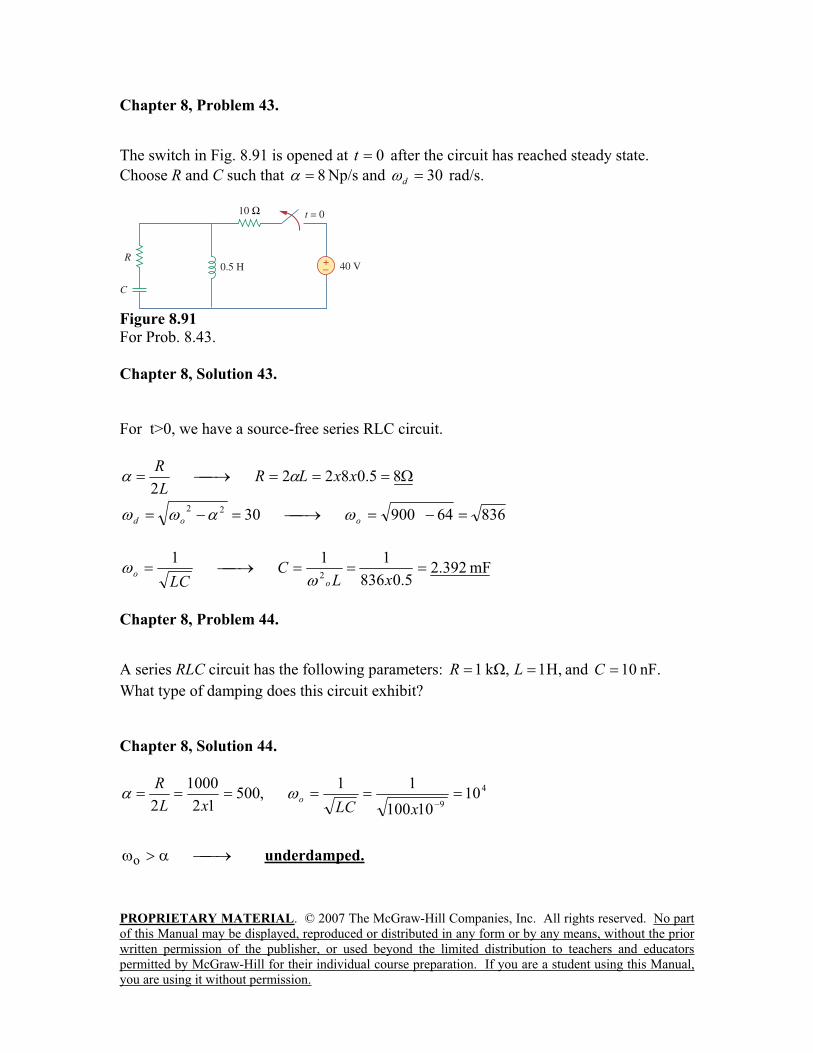
Chapter 8, Problem 43.
The switch in Fig. 8.91 is opened at 0t after the circuit has reached steady state.
Choose R and C such that 8 Np/s and 30d
rad/s.
Figure 8.91
For Prob. 8.43.
Chapter 8, Solution 43.
For t>0, we have a source-free series RLC circuit.
85.08222
xxLRL
R
836649003022
ood
mF392.25.0836
1112
xLC
LC o
o
Chapter 8, Problem 44.
A series RLC circuit has the following parameters: ,1,k1 LR and 10C nF.
What type of damping does this circuit exhibit?
Chapter 8, Solution 44.
4
910
10100
11,500
12
1000
2 xLCxL
Ro
o underdamped.
PROPRIETARY MATERIAL. © 2007 The McGraw-Hill Companies, Inc. All rights reserved. No part
of this Manual may be displayed, reproduced or distributed in any form or by any means, without the prior
written permission of the publisher, or used beyond the limited distribution to teachers and educators
permitted by McGraw-Hill for their individual course preparation. If you are a student using this Manual,
you are using it without permission.
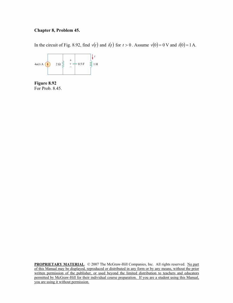
Chapter 8, Problem 45.
In the circuit of Fig. 8.92, find tv and ti for 0t . Assume 00v V and 10i A.
Figure 8.92
For Prob. 8.45.
PROPRIETARY MATERIAL. © 2007 The McGraw-Hill Companies, Inc. All rights reserved. No part
of this Manual may be displayed, reproduced or distributed in any form or by any means, without the prior
written permission of the publisher, or used beyond the limited distribution to teachers and educators
permitted by McGraw-Hill for their individual course preparation. If you are a student using this Manual,
you are using it without permission.
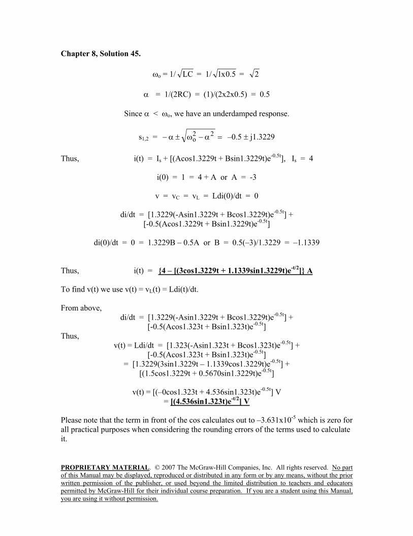
Chapter 8, Solution 45.
o = 1/ LC = 1/ 5.0x1 = 2
= 1/(2RC) = (1)/(2x2x0.5) = 0.5
Since < o, we have an underdamped response.
s1,2 =22
o –0.5 j1.3229
Thus, i(t) = Is + [(Acos1.3229t + Bsin1.3229t)e-0.5t
], Is = 4
i(0) = 1 = 4 + A or A = -3
v = vC = vL = Ldi(0)/dt = 0
di/dt = [1.3229(-Asin1.3229t + Bcos1.3229t)e-0.5t
] +
[-0.5(Acos1.3229t + Bsin1.3229t)e-0.5t
]
di(0)/dt = 0 = 1.3229B – 0.5A or B = 0.5(–3)/1.3229 = –1.1339
Thus, i(t) = 4 – [(3cos1.3229t + 1.1339sin1.3229t)e-t/2
] A
To find v(t) we use v(t) = vL(t) = Ldi(t)/dt.
From above,
di/dt = [1.3229(-Asin1.3229t + Bcos1.3229t)e-0.5t
] +
[-0.5(Acos1.323t + Bsin1.323t)e-0.5t
]
Thus,
v(t) = Ldi/dt = [1.323(-Asin1.323t + Bcos1.323t)e-0.5t
] +
[-0.5(Acos1.323t + Bsin1.323t)e-0.5t
]
= [1.3229(3sin1.3229t – 1.1339cos1.3229t)e-0.5t
] +
[(1.5cos1.3229t + 0.5670sin1.3229t)e-0.5t
]
v(t) = [(–0cos1.323t + 4.536sin1.323t)e-0.5t
] V
= [(4.536sin1.323t)e-t/2
] V
Please note that the term in front of the cos calculates out to –3.631x10⁻⁵
which is zero for
all practical purposes when considering the rounding errors of the terms used to calculate
it.
PROPRIETARY MATERIAL. © 2007 The McGraw-Hill Companies, Inc. All rights reserved. No part
of this Manual may be displayed, reproduced or distributed in any form or by any means, without the prior
written permission of the publisher, or used beyond the limited distribution to teachers and educators
permitted by McGraw-Hill for their individual course preparation. If you are a student using this Manual,
you are using it without permission.
Chapter 8, Problem 46.
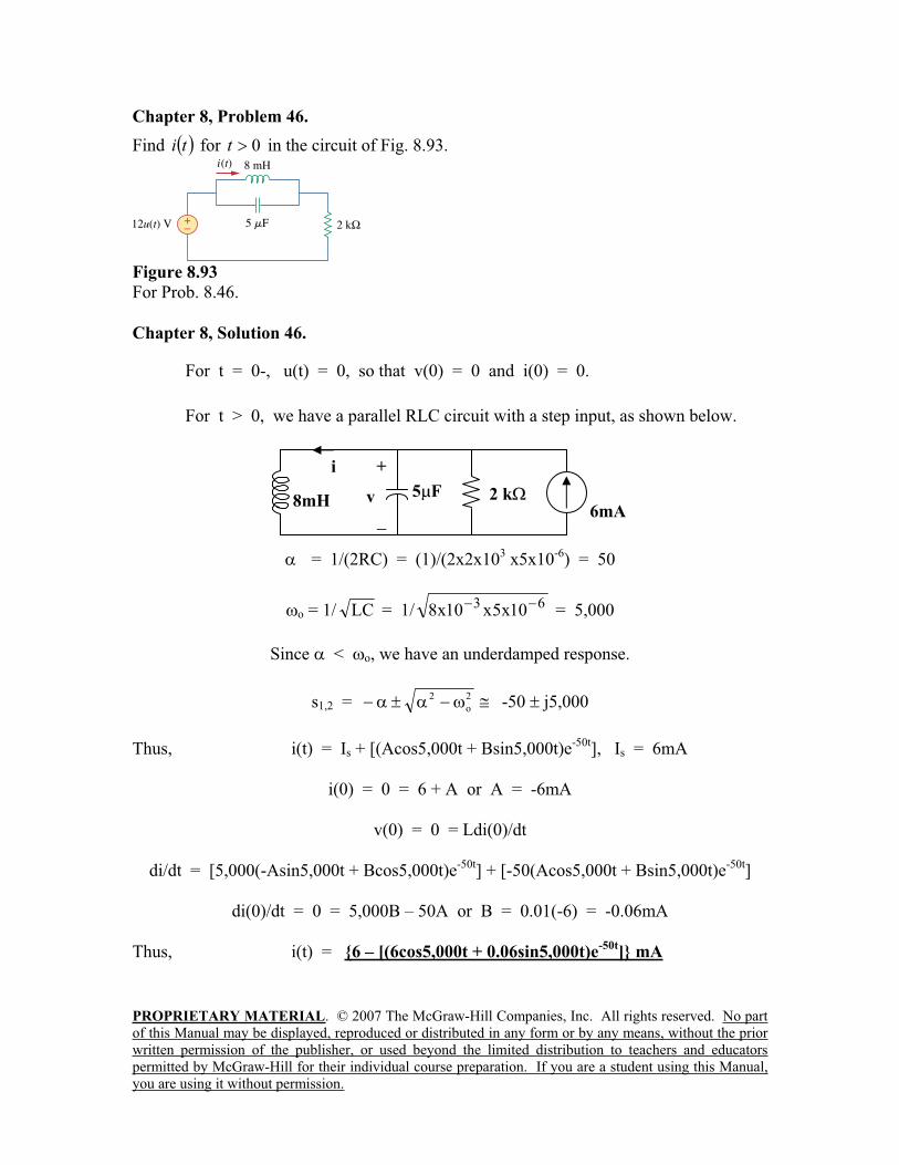
Find ti for 0t in the circuit of Fig. 8.93.
Figure 8.93
For Prob. 8.46.
Chapter 8, Solution 46.
For t = 0-, u(t) = 0, so that v(0) = 0 and i(0) = 0.
For t > 0, we have a parallel RLC circuit with a step input, as shown below.
= 1/(2RC) = (1)/(2x2x103 x5x10
-6) = 50
o = 1/ LC = 1/ 63 10x5x10x8 = 5,000
Since < o, we have an underdamped response.
s1,2 =2
o
2 -50 j5,000
Thus, i(t) = Is + [(Acos5,000t + Bsin5,000t)e-50t
], Is = 6mA
i(0) = 0 = 6 + A or A = -6mA
v(0) = 0 = Ldi(0)/dt
di/dt = [5,000(-Asin5,000t + Bcos5,000t)e-50t
] + [-50(Acos5,000t + Bsin5,000t)e-50t
]
di(0)/dt = 0 = 5,000B – 50A or B = 0.01(-6) = -0.06mA
Thus, i(t) = 6 – [(6cos5,000t + 0.06sin5,000t)e-50t
] mA
2 k
i +
v8mH5 F
6mA
PROPRIETARY MATERIAL. © 2007 The McGraw-Hill Companies, Inc. All rights reserved. No part
of this Manual may be displayed, reproduced or distributed in any form or by any means, without the prior
written permission of the publisher, or used beyond the limited distribution to teachers and educators
permitted by McGraw-Hill for their individual course preparation. If you are a student using this Manual,
you are using it without permission.
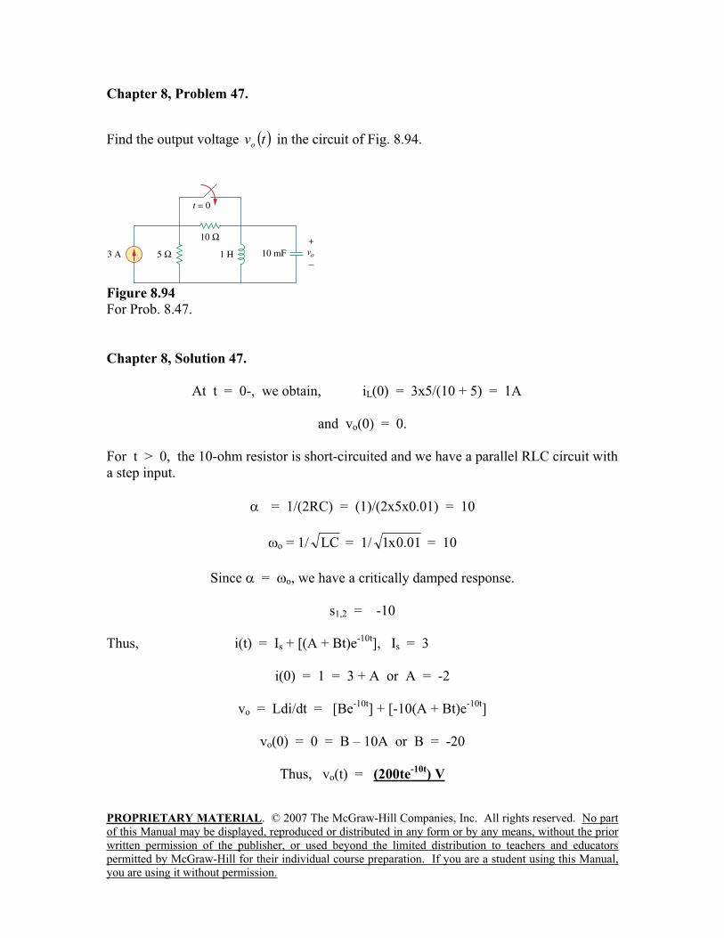
Chapter 8, Problem 47.
Find the output voltage tvo
in the circuit of Fig. 8.94.
Figure 8.94
For Prob. 8.47.
Chapter 8, Solution 47.
At t = 0-, we obtain, iL(0) = 3x5/(10 + 5) = 1A
and vo(0) = 0.
For t > 0, the 10-ohm resistor is short-circuited and we have a parallel RLC circuit with
a step input.
= 1/(2RC) = (1)/(2x5x0.01) = 10
o = 1/ LC = 1/ 01.0x1 = 10
Since = o, we have a critically damped response.
s1,2 = -10
Thus, i(t) = Is + [(A + Bt)e-10t
], Is = 3
i(0) = 1 = 3 + A or A = -2
vo = Ldi/dt = [Be-10t
] + [-10(A + Bt)e-10t
]
vo(0) = 0 = B – 10A or B = -20
Thus, vo(t) = (200te-10t
) V
PROPRIETARY MATERIAL. © 2007 The McGraw-Hill Companies, Inc. All rights reserved. No part
of this Manual may be displayed, reproduced or distributed in any form or by any means, without the prior
written permission of the publisher, or used beyond the limited distribution to teachers and educators
permitted by McGraw-Hill for their individual course preparation. If you are a student using this Manual,
you are using it without permission.
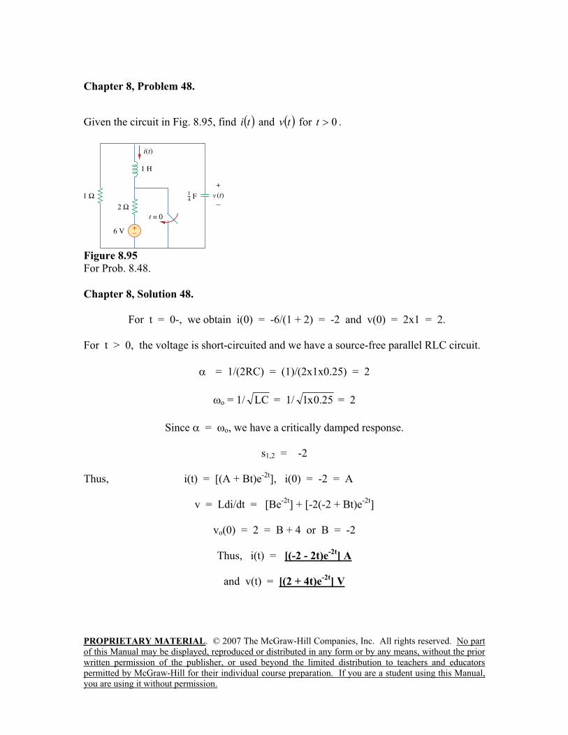
Chapter 8, Problem 48.
Given the circuit in Fig. 8.95, find ti and tv for 0t .
Figure 8.95
For Prob. 8.48.
Chapter 8, Solution 48.
For t = 0-, we obtain i(0) = -6/(1 + 2) = -2 and v(0) = 2x1 = 2.
For t > 0, the voltage is short-circuited and we have a source-free parallel RLC circuit.
= 1/(2RC) = (1)/(2x1x0.25) = 2
o = 1/ LC = 1/ 25.0x1 = 2
Since = o, we have a critically damped response.
s1,2 = -2
Thus, i(t) = [(A + Bt)e-2t
], i(0) = -2 = A
v = Ldi/dt = [Be-2t
] + [-2(-2 + Bt)e-2t
]
vo(0) = 2 = B + 4 or B = -2
Thus, i(t) = [(-2 - 2t)e-2t
] A
and v(t) = [(2 + 4t)e-2t
] V
PROPRIETARY MATERIAL. © 2007 The McGraw-Hill Companies, Inc. All rights reserved. No part
of this Manual may be displayed, reproduced or distributed in any form or by any means, without the prior
written permission of the publisher, or used beyond the limited distribution to teachers and educators
permitted by McGraw-Hill for their individual course preparation. If you are a student using this Manual,
you are using it without permission.
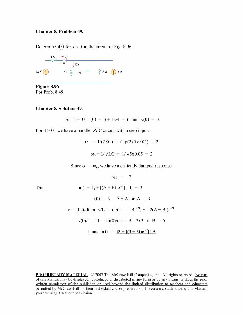
Chapter 8, Problem 49.
Determine ti for 0t in the circuit of Fig. 8.96.
Figure 8.96
For Prob. 8.49.
Chapter 8, Solution 49.
For t = 0-, i(0) = 3 + 12/4 = 6 and v(0) = 0.
For t > 0, we have a parallel RLC circuit with a step input.
= 1/(2RC) = (1)/(2x5x0.05) = 2
o = 1/ LC = 1/ 05.0x5 = 2
Since = o, we have a critically damped response.
s1,2 = -2
Thus, i(t) = Is + [(A + Bt)e-2t
], Is = 3
i(0) = 6 = 3 + A or A = 3
v = Ldi/dt or v/L = di/dt = [Be-2t
] + [-2(A + Bt)e-2t
]
v(0)/L = 0 = di(0)/dt = B – 2x3 or B = 6
Thus, i(t) = 3 + [(3 + 6t)e-2t
] A
PROPRIETARY MATERIAL. © 2007 The McGraw-Hill Companies, Inc. All rights reserved. No part
of this Manual may be displayed, reproduced or distributed in any form or by any means, without the prior
written permission of the publisher, or used beyond the limited distribution to teachers and educators
permitted by McGraw-Hill for their individual course preparation. If you are a student using this Manual,
you are using it without permission.
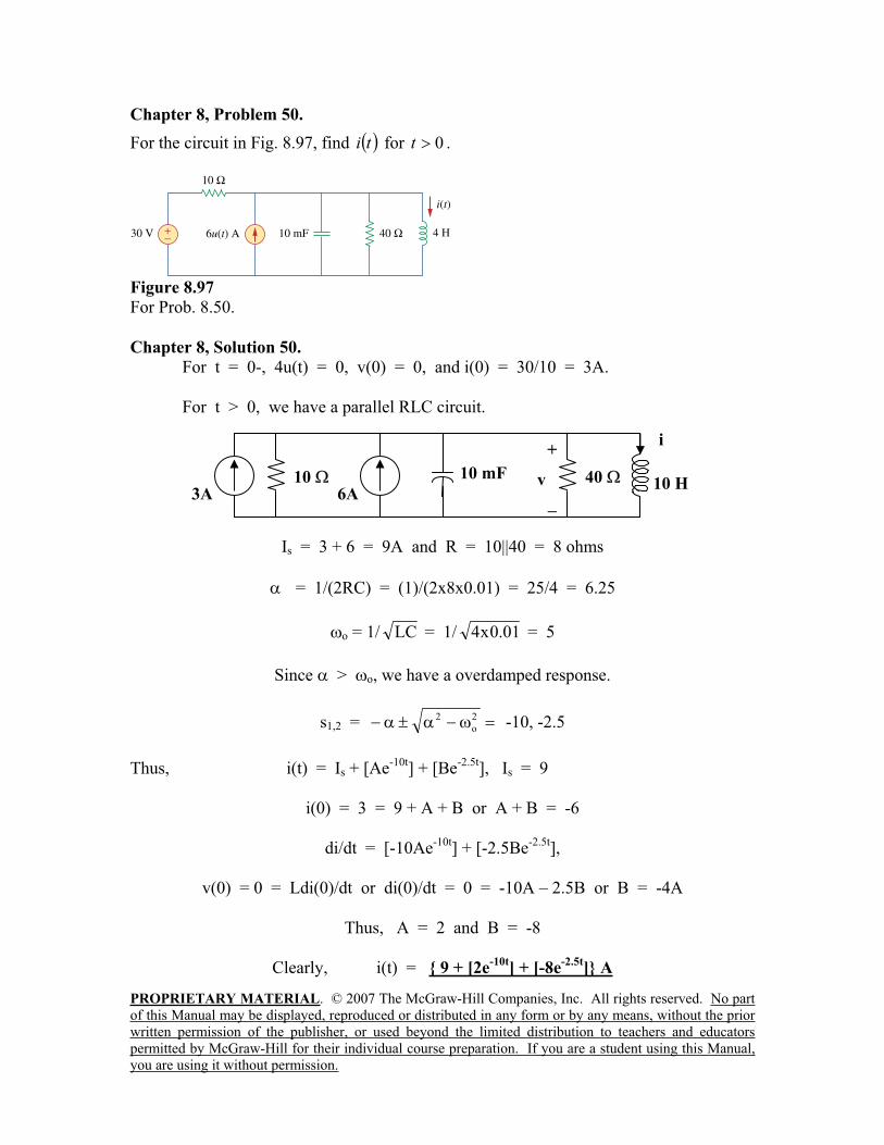
Chapter 8, Problem 50.
For the circuit in Fig. 8.97, find ti for 0t .
Figure 8.97
For Prob. 8.50.
Chapter 8, Solution 50.
For t = 0-, 4u(t) = 0, v(0) = 0, and i(0) = 30/10 = 3A.
For t > 0, we have a parallel RLC circuit.
Is = 3 + 6 = 9A and R = 10||40 = 8 ohms
= 1/(2RC) = (1)/(2x8x0.01) = 25/4 = 6.25
o = 1/ LC = 1/ 01.0x4 = 5
Since > o, we have a overdamped response.
s1,2 =2
o
2 -10, -2.5
Thus, i(t) = Is + [Ae-10t
] + [Be-2.5t
], Is = 9
i(0) = 3 = 9 + A + B or A + B = -6
di/dt = [-10Ae-10t
] + [-2.5Be-2.5t
],
v(0) = 0 = Ldi(0)/dt or di(0)/dt = 0 = -10A – 2.5B or B = -4A
Thus, A = 2 and B = -8
Clearly, i(t) = 9 + [2e-10t
] + [-8e-2.5t
] A
10
i+
v 10 H 10 mF
3A 6A40
PROPRIETARY MATERIAL. © 2007 The McGraw-Hill Companies, Inc. All rights reserved. No part
of this Manual may be displayed, reproduced or distributed in any form or by any means, without the prior
written permission of the publisher, or used beyond the limited distribution to teachers and educators
permitted by McGraw-Hill for their individual course preparation. If you are a student using this Manual,
you are using it without permission.
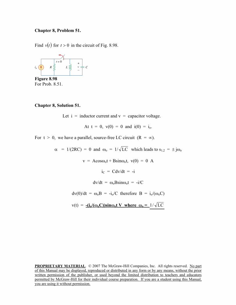
Chapter 8, Problem 51.
Find tv for 0t in the circuit of Fig. 8.98.
Figure 8.98
For Prob. 8.51.
Chapter 8, Solution 51.
Let i = inductor current and v = capacitor voltage.
At t = 0, v(0) = 0 and i(0) = io.
For t > 0, we have a parallel, source-free LC circuit (R = ).
= 1/(2RC) = 0 and o = 1/ LC which leads to s1,2 = j o
v = Acos ot + Bsin ot, v(0) = 0 A
iC = Cdv/dt = -i
dv/dt = oBsin ot = -i/C
dv(0)/dt = oB = -io/C therefore B = io/( oC)
v(t) = -(io/( oC))sin ot V where o = LC/1
PROPRIETARY MATERIAL. © 2007 The McGraw-Hill Companies, Inc. All rights reserved. No part
of this Manual may be displayed, reproduced or distributed in any form or by any means, without the prior
written permission of the publisher, or used beyond the limited distribution to teachers and educators
permitted by McGraw-Hill for their individual course preparation. If you are a student using this Manual,
you are using it without permission.
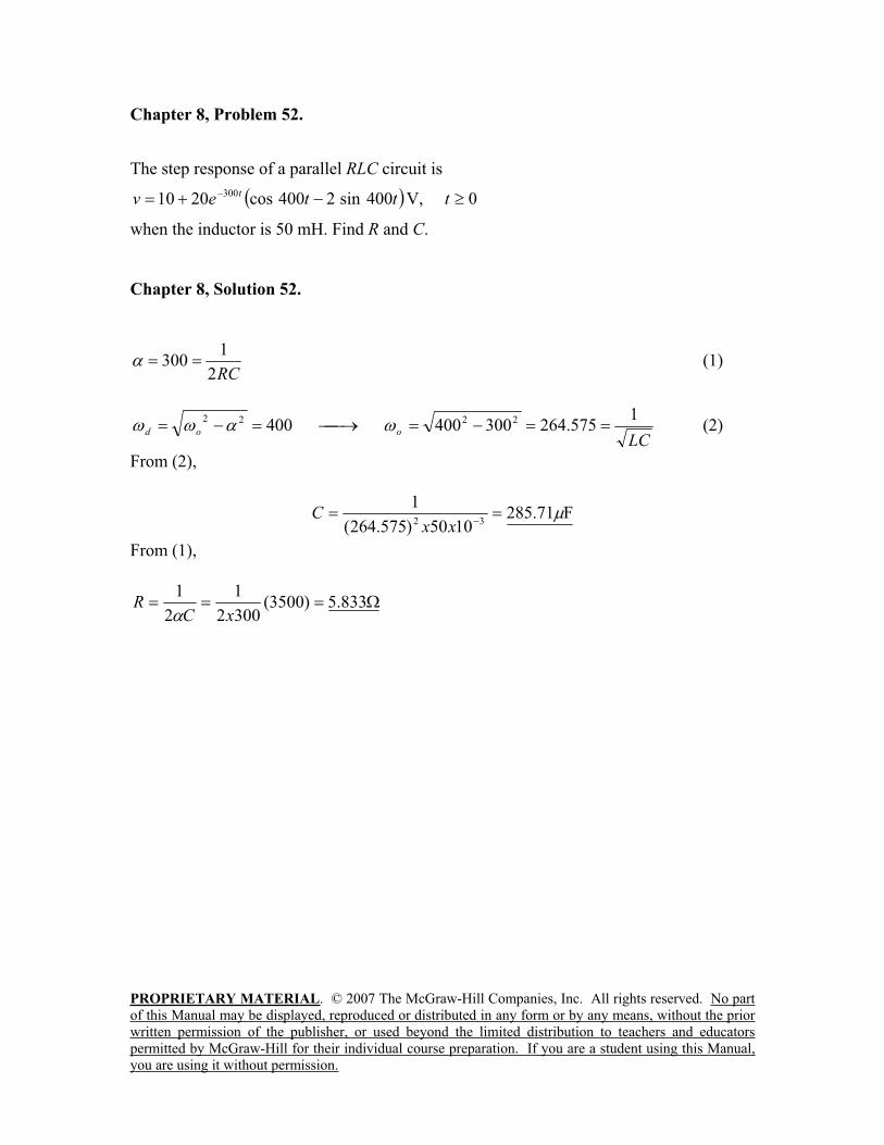
Chapter 8, Problem 52.
The step response of a parallel RLC circuit is
ttevt 400sin2400cos2010 300 V, 0t
when the inductor is 50 mH. Find R and C.
Chapter 8, Solution 52.
RC2
1300 (1)
LCood
1575.264300400400 2222
(2)
From (2),
F71.2851050)575.264(
132
xxC
From (1),
833.5)3500(3002
1
2
1
xCR
PROPRIETARY MATERIAL. © 2007 The McGraw-Hill Companies, Inc. All rights reserved. No part
of this Manual may be displayed, reproduced or distributed in any form or by any means, without the prior
written permission of the publisher, or used beyond the limited distribution to teachers and educators
permitted by McGraw-Hill for their individual course preparation. If you are a student using this Manual,
you are using it without permission.
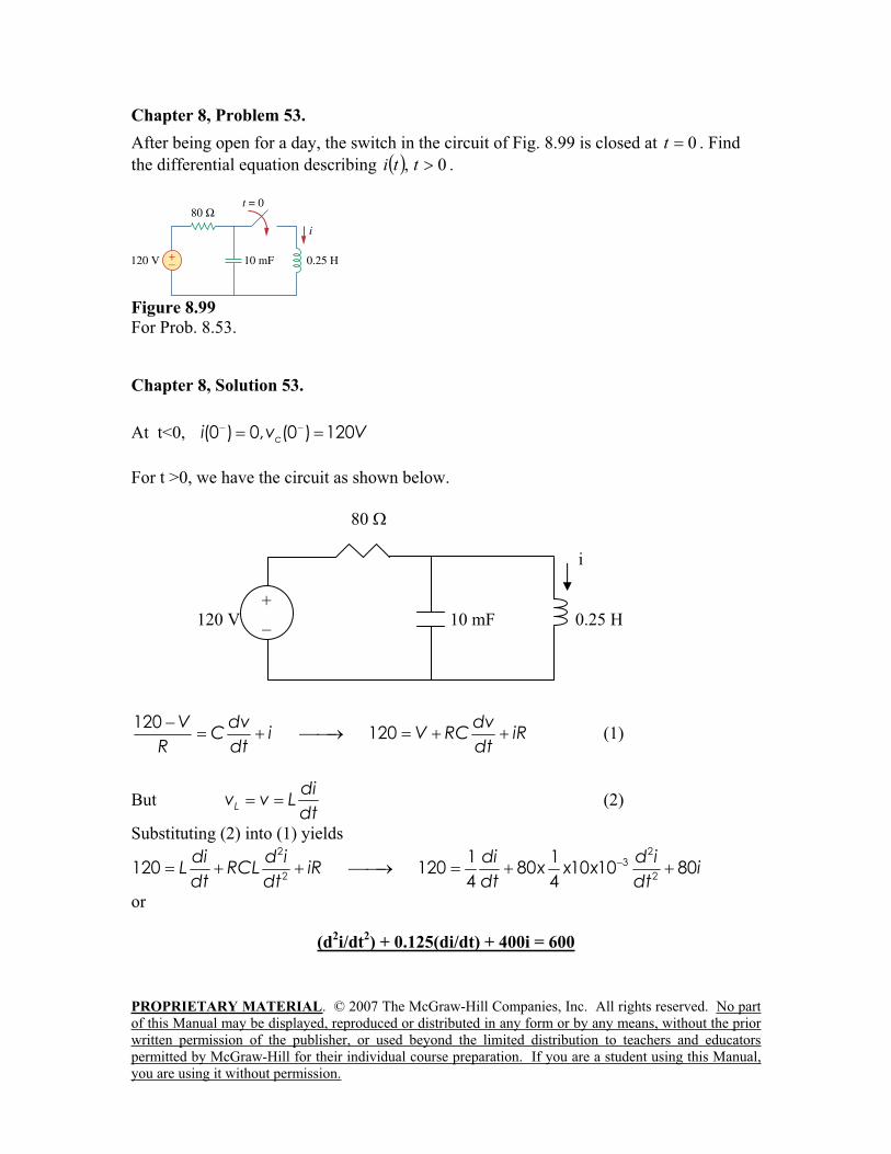
Chapter 8, Problem 53.
After being open for a day, the switch in the circuit of Fig. 8.99 is closed at 0t . Find
the differential equation describing 0, tti .
Figure 8.99
For Prob. 8.53.
Chapter 8, Solution 53.
At t<0, (0 ) 0, (0 ) 120ci v V
For t >0, we have the circuit as shown below.
80
i
120 V 10 mF 0.25 H
120120
V dv dvC i V RC iR
R dt dt (1)
But L
div v L
dt (2)
Substituting (2) into (1) yields 2 2
3
2 2
1 1120 120 80 10 10 80
4 4
di d i di d iL RCL iR x x x idt dtdt dt
or
(d2i/dt
2) + 0.125(di/dt) + 400i = 600
+
_
PROPRIETARY MATERIAL. © 2007 The McGraw-Hill Companies, Inc. All rights reserved. No part
of this Manual may be displayed, reproduced or distributed in any form or by any means, without the prior
written permission of the publisher, or used beyond the limited distribution to teachers and educators
permitted by McGraw-Hill for their individual course preparation. If you are a student using this Manual,
you are using it without permission.
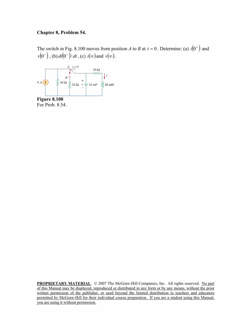
Chapter 8, Problem 54.
The switch in Fig. 8.100 moves from position A to B at 0t . Determine: (a) 0i and
0v , (b) dtdi /0 , (c) i and v .
Figure 8.100
For Prob. 8.54.
PROPRIETARY MATERIAL. © 2007 The McGraw-Hill Companies, Inc. All rights reserved. No part
of this Manual may be displayed, reproduced or distributed in any form or by any means, without the prior
written permission of the publisher, or used beyond the limited distribution to teachers and educators
permitted by McGraw-Hill for their individual course preparation. If you are a student using this Manual,
you are using it without permission.
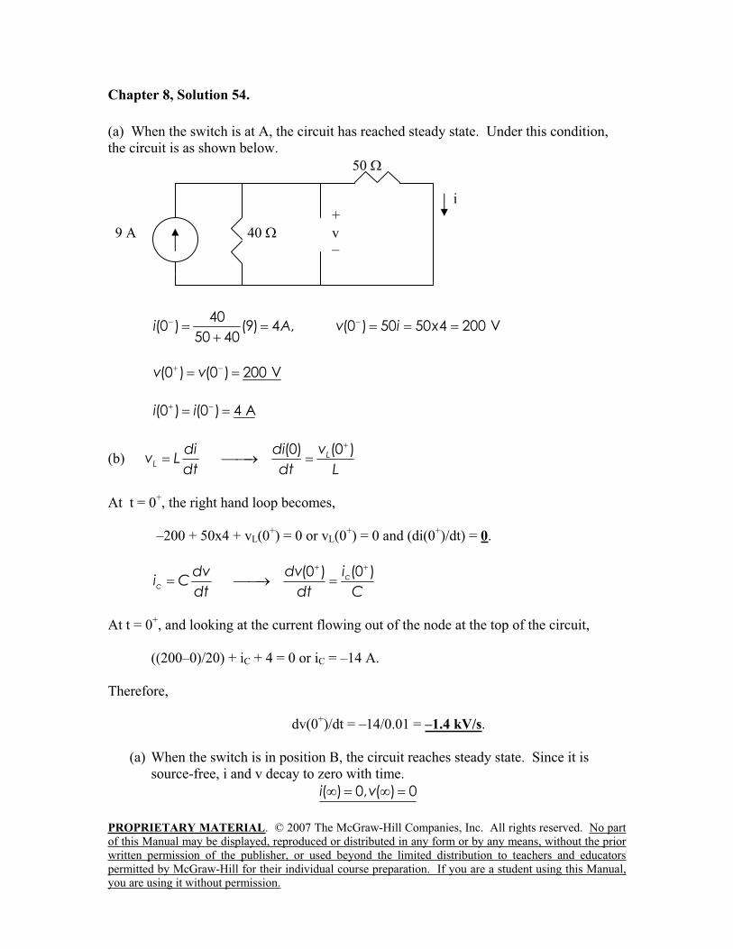
Chapter 8, Solution 54.
(a) When the switch is at A, the circuit has reached steady state. Under this condition,
the circuit is as shown below.
50
i
+
9 A 40 v
–
40(0 ) (9) 4 , (0 ) 50 50 4 200 V
50 40i A v i x
(0 ) (0 ) 200 Vv v
(0 ) (0 ) 4 Ai i
(b)(0) (0 )L
L
di di vv L
dt dt L
At t = 0+, the right hand loop becomes,
–200 + 50x4 + vL(0+) = 0 or vL(0
+) = 0 and (di(0
+)/dt) = 0.
(0 )(0 ) cc
idv dvi C
dt dt C
At t = 0+, and looking at the current flowing out of the node at the top of the circuit,
((200–0)/20) + iC + 4 = 0 or iC = –14 A.
Therefore,
dv(0+)/dt = –14/0.01 = –1.4 kV/s.
(a) When the switch is in position B, the circuit reaches steady state. Since it is
source-free, i and v decay to zero with time.
( ) 0, ( ) 0i v
PROPRIETARY MATERIAL. © 2007 The McGraw-Hill Companies, Inc. All rights reserved. No part
of this Manual may be displayed, reproduced or distributed in any form or by any means, without the prior
written permission of the publisher, or used beyond the limited distribution to teachers and educators
permitted by McGraw-Hill for their individual course preparation. If you are a student using this Manual,
you are using it without permission.
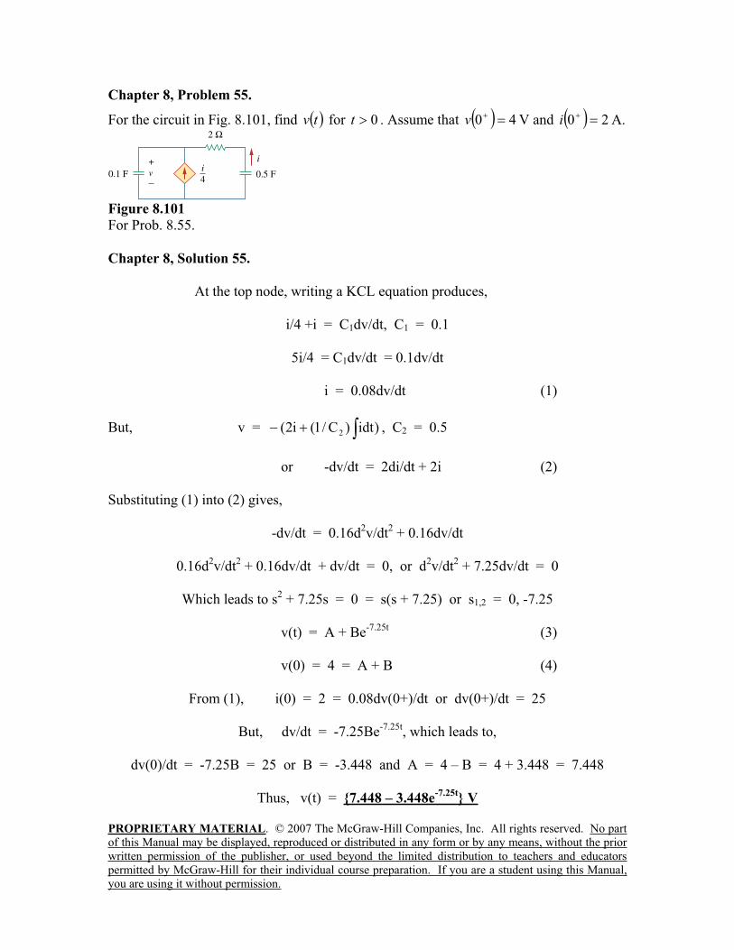
Chapter 8, Problem 55.
For the circuit in Fig. 8.101, find tv for 0t . Assume that 40v V and 20i A.
Figure 8.101
For Prob. 8.55.
Chapter 8, Solution 55.
At the top node, writing a KCL equation produces,
i/4 +i = C1dv/dt, C1 = 0.1
5i/4 = C1dv/dt = 0.1dv/dt
i = 0.08dv/dt (1)
But, v = )idt)C/1(i2( 2 , C2 = 0.5
or -dv/dt = 2di/dt + 2i (2)
Substituting (1) into (2) gives,
-dv/dt = 0.16d2v/dt
2 + 0.16dv/dt
0.16d2v/dt
2 + 0.16dv/dt + dv/dt = 0, or d
2v/dt
2 + 7.25dv/dt = 0
Which leads to s2 + 7.25s = 0 = s(s + 7.25) or s1,2 = 0, -7.25
v(t) = A + Be-7.25t
(3)
v(0) = 4 = A + B (4)
From (1), i(0) = 2 = 0.08dv(0+)/dt or dv(0+)/dt = 25
But, dv/dt = -7.25Be-7.25t
, which leads to,
dv(0)/dt = -7.25B = 25 or B = -3.448 and A = 4 – B = 4 + 3.448 = 7.448
Thus, v(t) = 7.448 – 3.448e-7.25t
V
PROPRIETARY MATERIAL. © 2007 The McGraw-Hill Companies, Inc. All rights reserved. No part
of this Manual may be displayed, reproduced or distributed in any form or by any means, without the prior
written permission of the publisher, or used beyond the limited distribution to teachers and educators
permitted by McGraw-Hill for their individual course preparation. If you are a student using this Manual,
you are using it without permission.
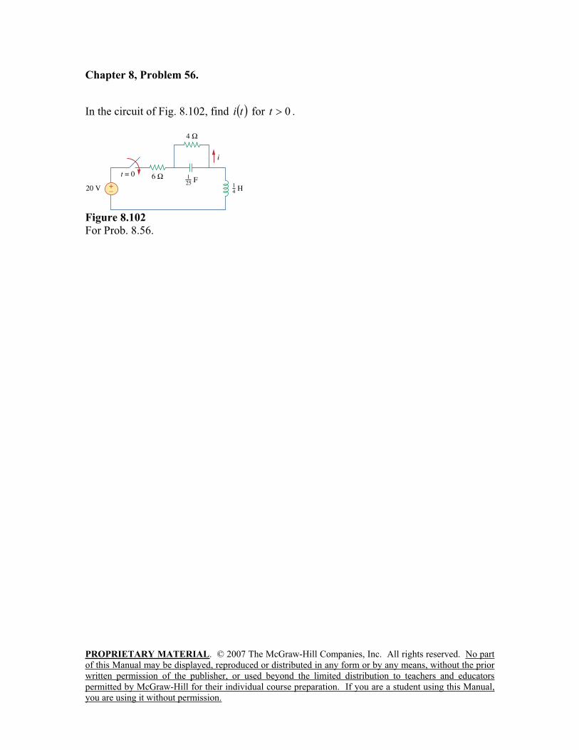
Chapter 8, Problem 56.
In the circuit of Fig. 8.102, find ti for 0t .
Figure 8.102
For Prob. 8.56.
PROPRIETARY MATERIAL. © 2007 The McGraw-Hill Companies, Inc. All rights reserved. No part of this Manual may be displayed, reproduced or distributed in any form or by any means, without the prior written permission of the publisher, or used beyond the limited distribution to teachers and educators permitted by McGraw-Hill for their individual course preparation. If you are a student using this Manual, you are using it without permission.
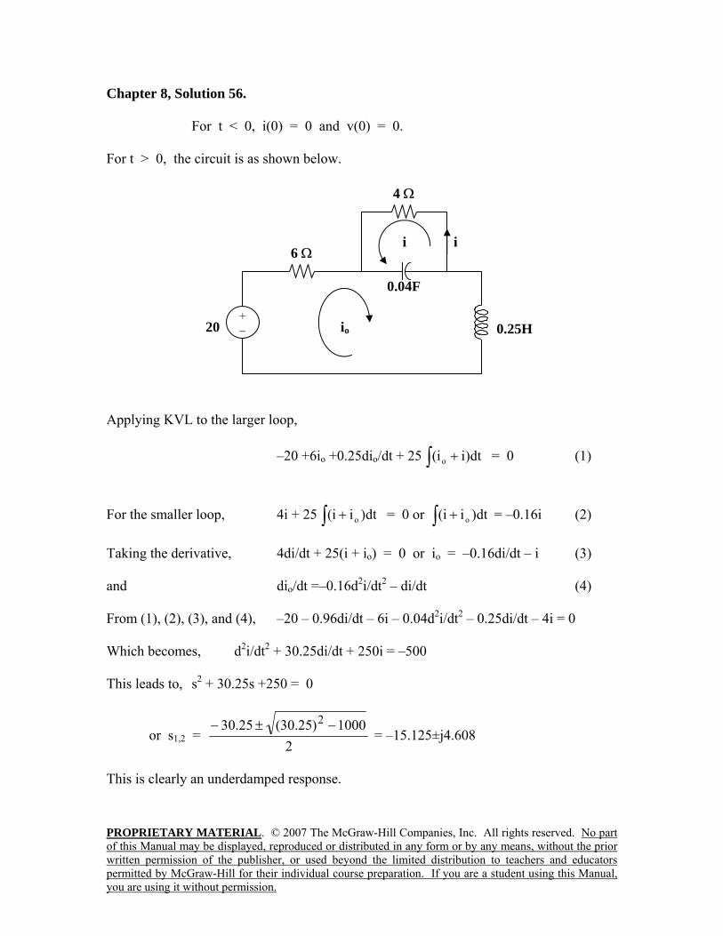
Chapter 8, Solution 56. For t < 0, i(0) = 0 and v(0) = 0. For t > 0, the circuit is as shown below. Applying KVL to the larger loop,
–20 +6io +0.25dio/dt + 25 ∫ + dt)ii( o = 0 (1)
For the smaller loop, 4i + 25 ∫ + dt)ii( o = 0 or ∫ + dt)ii( o = –0.16i (2) Taking the derivative, 4di/dt + 25(i + io) = 0 or io = –0.16di/dt – i (3) and dio/dt =–0.16d2i/dt2 – di/dt (4) From (1), (2), (3), and (4), –20 – 0.96di/dt – 6i – 0.04d2i/dt2 – 0.25di/dt – 4i = 0 Which becomes, d2i/dt2 + 30.25di/dt + 250i = –500 This leads to, s2 + 30.25s +250 = 0
or s1,2 = 2
1000)25.30(25.30 2 −±− = –15.125±j4.608
This is clearly an underdamped response.
4 Ω
i
0.25H
0.04F
20
+ −
6 Ωi
io
PROPRIETARY MATERIAL. © 2007 The McGraw-Hill Companies, Inc. All rights reserved. No part of this Manual may be displayed, reproduced or distributed in any form or by any means, without the prior written permission of the publisher, or used beyond the limited distribution to teachers and educators permitted by McGraw-Hill for their individual course preparation. If you are a student using this Manual, you are using it without permission.
Thus, i(t) = Is + e–15.125t(A1cos(4.608t) + A2sin(4.608t))A. At t = 0, io(0) = 0 and i(0) = 0 = Is + A1 or A1 = –Is. As t approaches infinity, io(∞) = 20/10 = 2A = –i(∞) or i(∞) = –2A = Is and A1 = 2. In addition, from (3), we get di(0)/dt = –6.25io(0) – 6.25i(0) = 0. di/dt = 0 – 15.125 e–15.125t(A1cos(4.608t) + A2sin(4.608t)) + e–15.125t(–A14.608sin(4.608t) + A24.608cos(4.608t)). At t=0, di(0)/dt = 0 = –15.125A1 + 4.608A2 = –30.25 + 4.608A2 or A2 = 30.25/4.608 = 6.565. This leads to,
i(t) = (-2 + e–15.125t(2cos(4.608t) + 6.565sin(4.608t)) A

PROPRIETARY MATERIAL. © 2007 The McGraw-Hill Companies, Inc. All rights reserved. No part
of this Manual may be displayed, reproduced or distributed in any form or by any means, without the prior
written permission of the publisher, or used beyond the limited distribution to teachers and educators
permitted by McGraw-Hill for their individual course preparation. If you are a student using this Manual,
you are using it without permission.
Chapter 8, Problem 57.
If the switch in Fig. 8.103 has been closed for a long time before 0t , but is opened at
0t determine:
(a) the characteristic equation of the circuit,
(b)xi and
Rv for 0t .
Figure 8.103
For Prob. 8.57.
Chapter 8, Solution 57.
(a) Let v = capacitor voltage and i = inductor current. At t = 0-, the switch is
closed and the circuit has reached steady-state.
v(0-) = 16V and i(0-) = 16/8 = 2A
At t = 0+, the switch is open but, v(0+) = 16 and i(0+) = 2.
We now have a source-free RLC circuit.
R 8 + 12 = 20 ohms, L = 1H, C = 4mF.
= R/(2L) = (20)/(2x1) = 10
o = 1/ LC = 1/ )36/1(x1 = 6
Since > o, we have a overdamped response.
s1,2 =2
o
2 -18, -2
Thus, the characteristic equation is (s + 2)(s + 18) = 0 or s2 + 20s +36 = 0.
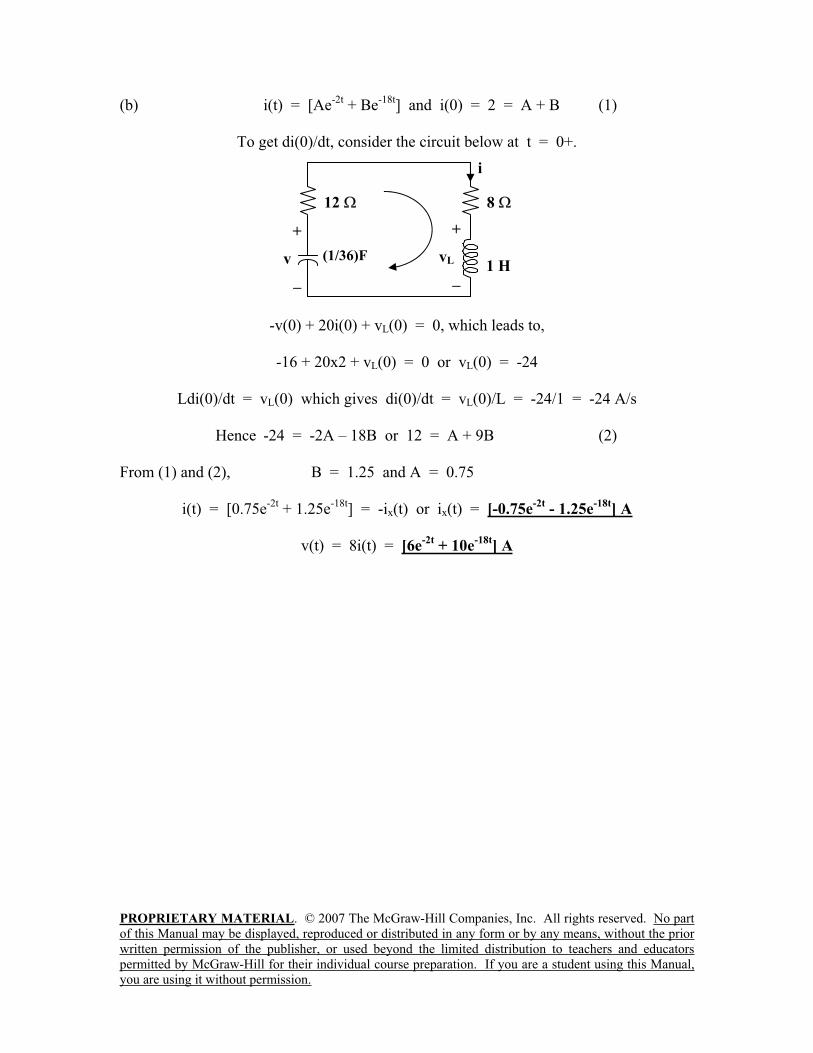
PROPRIETARY MATERIAL. © 2007 The McGraw-Hill Companies, Inc. All rights reserved. No part
of this Manual may be displayed, reproduced or distributed in any form or by any means, without the prior
written permission of the publisher, or used beyond the limited distribution to teachers and educators
permitted by McGraw-Hill for their individual course preparation. If you are a student using this Manual,
you are using it without permission.
(b) i(t) = [Ae-2t
+ Be-18t
] and i(0) = 2 = A + B (1)
To get di(0)/dt, consider the circuit below at t = 0+.
-v(0) + 20i(0) + vL(0) = 0, which leads to,
-16 + 20x2 + vL(0) = 0 or vL(0) = -24
Ldi(0)/dt = vL(0) which gives di(0)/dt = vL(0)/L = -24/1 = -24 A/s
Hence -24 = -2A – 18B or 12 = A + 9B (2)
From (1) and (2), B = 1.25 and A = 0.75
i(t) = [0.75e-2t
+ 1.25e-18t
] = -ix(t) or ix(t) = [-0.75e-2t
- 1.25e-18t
] A
v(t) = 8i(t) = [6e-2t
+ 10e-18t
] A
8
i
+
v1 H
(1/36)F
12
+
vL

PROPRIETARY MATERIAL. © 2007 The McGraw-Hill Companies, Inc. All rights reserved. No part
of this Manual may be displayed, reproduced or distributed in any form or by any means, without the prior
written permission of the publisher, or used beyond the limited distribution to teachers and educators
permitted by McGraw-Hill for their individual course preparation. If you are a student using this Manual,
you are using it without permission.
Chapter 8, Problem 58.
In the circuit of Fig. 8.104, the switch has been in position 1 for a long time but moved to
position 2 at 0t Find:
(a) dtdvv /0,0
(b) tv for 0t
Figure 8.104
For Prob. 8.58.
Chapter 8, Solution 58.
(a) Let i =inductor current, v = capacitor voltage i(0) =0, v(0) = 4
V/s85.0
)04()]0()0([)0(
RC
Riv
dt
dv
(b) For 0t , the circuit is a source-free RLC parallel circuit.
2125.0
11,1
15.02
1
2
1
xLCxxRCo
732.11422od
Thus,
)732.1sin732.1cos()( 21 tAtAetvt
v(0) = 4 = A1
tAetAetAetAedt
dv tttt 732.1cos732.1732.1sin732.1sin732.1732.1cos 2211
309.2732.18)0(
221 AAAdt
dv
)732.1sin309.2732.1cos4()( ttetvt V
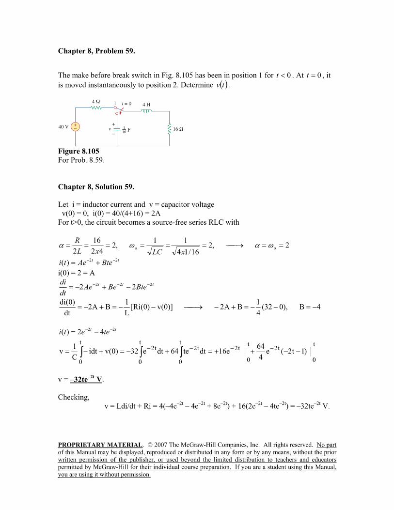
PROPRIETARY MATERIAL. © 2007 The McGraw-Hill Companies, Inc. All rights reserved. No part
of this Manual may be displayed, reproduced or distributed in any form or by any means, without the prior
written permission of the publisher, or used beyond the limited distribution to teachers and educators
permitted by McGraw-Hill for their individual course preparation. If you are a student using this Manual,
you are using it without permission.
Chapter 8, Problem 59.
The make before break switch in Fig. 8.105 has been in position 1 for 0t . At 0t , it
is moved instantaneously to position 2. Determine tv .
Figure 8.105
For Prob. 8.59.
Chapter 8, Solution 59.
Let i = inductor current and v = capacitor voltage
v(0) = 0, i(0) = 40/(4+16) = 2A
For t>0, the circuit becomes a source-free series RLC with
2,216/14
11,2
42
16
2oo
xLCxL
R
ttBteAeti
22)(
i(0) = 2 = A
tttBteBeAe
dt
di 222 22
4B),032(4
1BA2)]0(v)0(Ri[
L
1BA2
dt
)0(di
ttteeti
22 42)(
t
0
t2t
0
t
0
t2t2t
0
t2t
0
)1t2(e4
64e16dtte64dte32)0(vidt
C
1v
v = –32te–2t
V.
Checking,
v = Ldi/dt + Ri = 4(–4e–2t
– 4e–2t
+ 8e–2t
) + 16(2e–2t
– 4te–2t
) = –32te–2t
V.
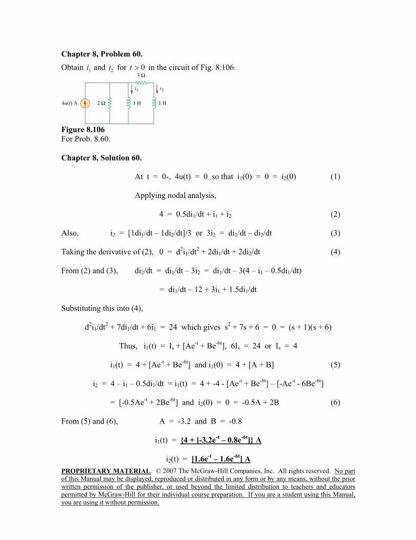
PROPRIETARY MATERIAL. © 2007 The McGraw-Hill Companies, Inc. All rights reserved. No part
of this Manual may be displayed, reproduced or distributed in any form or by any means, without the prior
written permission of the publisher, or used beyond the limited distribution to teachers and educators
permitted by McGraw-Hill for their individual course preparation. If you are a student using this Manual,
you are using it without permission.
Chapter 8, Problem 60.
Obtain 1i and 2i for 0t in the circuit of Fig. 8.106.
Figure 8.106
For Prob. 8.60.
Chapter 8, Solution 60.
At t = 0-, 4u(t) = 0 so that i1(0) = 0 = i2(0) (1)
Applying nodal analysis,
4 = 0.5di1/dt + i1 + i2 (2)
Also, i2 = [1di1/dt – 1di2/dt]/3 or 3i2 = di1/dt – di2/dt (3)
Taking the derivative of (2), 0 = d2i1/dt
2 + 2di1/dt + 2di2/dt (4)
From (2) and (3), di2/dt = di1/dt – 3i2 = di1/dt – 3(4 – i1 – 0.5di1/dt)
= di1/dt – 12 + 3i1 + 1.5di1/dt
Substituting this into (4),
d2i1/dt
2 + 7di1/dt + 6i1 = 24 which gives s
2 + 7s + 6 = 0 = (s + 1)(s + 6)
Thus, i1(t) = Is + [Ae-t + Be
-6t], 6Is = 24 or Is = 4
i1(t) = 4 + [Ae-t + Be
-6t] and i1(0) = 4 + [A + B] (5)
i2 = 4 – i1 – 0.5di1/dt = i1(t) = 4 + -4 - [Ae-t + Be
-6t] – [-Ae
-t - 6Be
-6t]
= [-0.5Ae-t + 2Be
-6t] and i2(0) = 0 = -0.5A + 2B (6)
From (5) and (6), A = -3.2 and B = -0.8
i1(t) = 4 + [-3.2e-t – 0.8e
-6t] A
i2(t) = [1.6e-t – 1.6e
-6t] A
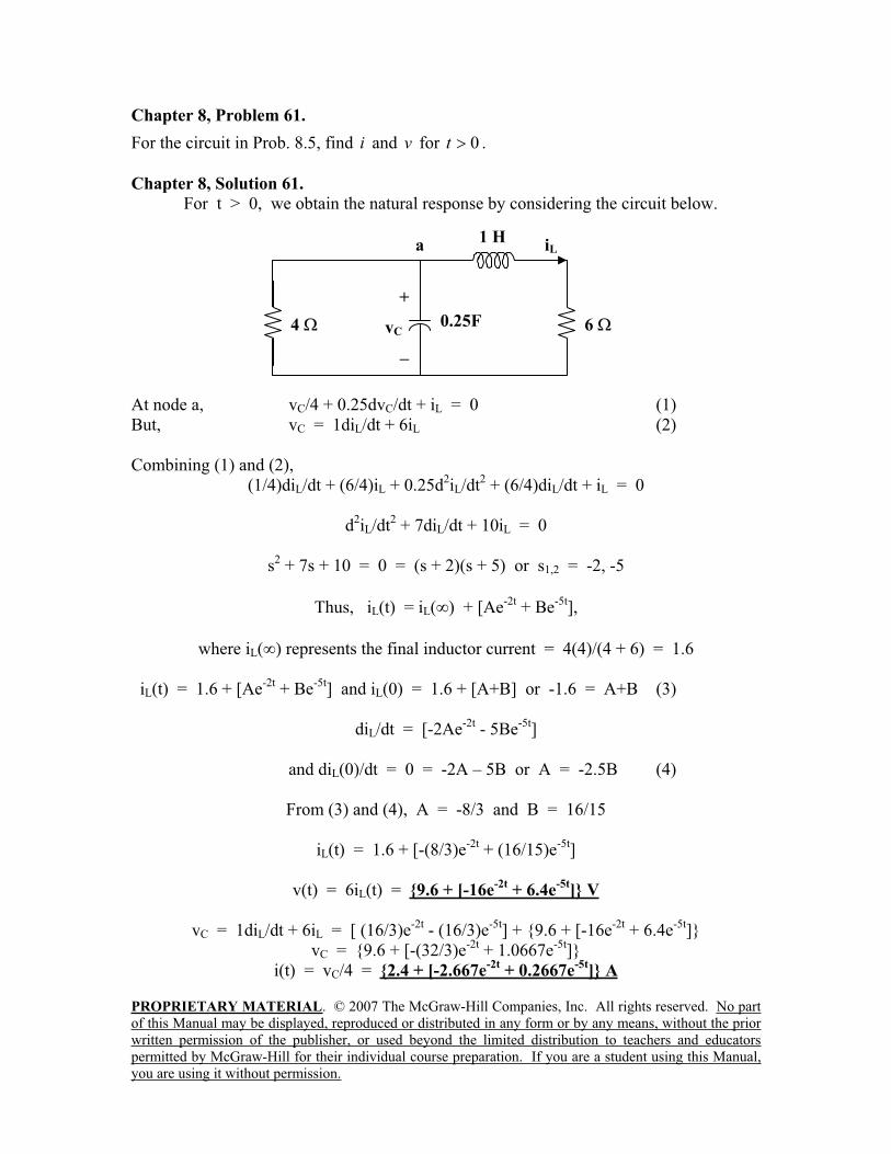
PROPRIETARY MATERIAL. © 2007 The McGraw-Hill Companies, Inc. All rights reserved. No part
of this Manual may be displayed, reproduced or distributed in any form or by any means, without the prior
written permission of the publisher, or used beyond the limited distribution to teachers and educators
permitted by McGraw-Hill for their individual course preparation. If you are a student using this Manual,
you are using it without permission.
Chapter 8, Problem 61.
For the circuit in Prob. 8.5, find i and v for 0t .
Chapter 8, Solution 61.
For t > 0, we obtain the natural response by considering the circuit below.
At node a, vC/4 + 0.25dvC/dt + iL = 0 (1)
But, vC = 1diL/dt + 6iL (2)
Combining (1) and (2),
(1/4)diL/dt + (6/4)iL + 0.25d2iL/dt
2 + (6/4)diL/dt + iL = 0
d2iL/dt
2 + 7diL/dt + 10iL = 0
s2 + 7s + 10 = 0 = (s + 2)(s + 5) or s1,2 = -2, -5
Thus, iL(t) = iL( ) + [Ae-2t
+ Be-5t
],
where iL( ) represents the final inductor current = 4(4)/(4 + 6) = 1.6
iL(t) = 1.6 + [Ae-2t
+ Be-5t
] and iL(0) = 1.6 + [A+B] or -1.6 = A+B (3)
diL/dt = [-2Ae-2t
- 5Be-5t
]
and diL(0)/dt = 0 = -2A – 5B or A = -2.5B (4)
From (3) and (4), A = -8/3 and B = 16/15
iL(t) = 1.6 + [-(8/3)e-2t
+ (16/15)e-5t
]
v(t) = 6iL(t) = 9.6 + [-16e-2t
+ 6.4e-5t
] V
vC = 1diL/dt + 6iL = [ (16/3)e-2t
- (16/3)e-5t
] + 9.6 + [-16e-2t
+ 6.4e-5t
]
vC = 9.6 + [-(32/3)e-2t
+ 1.0667e-5t
]
i(t) = vC/4 = 2.4 + [-2.667e-2t
+ 0.2667e-5t
] A
4
iLa
+
vC
1 H
0.25F 6
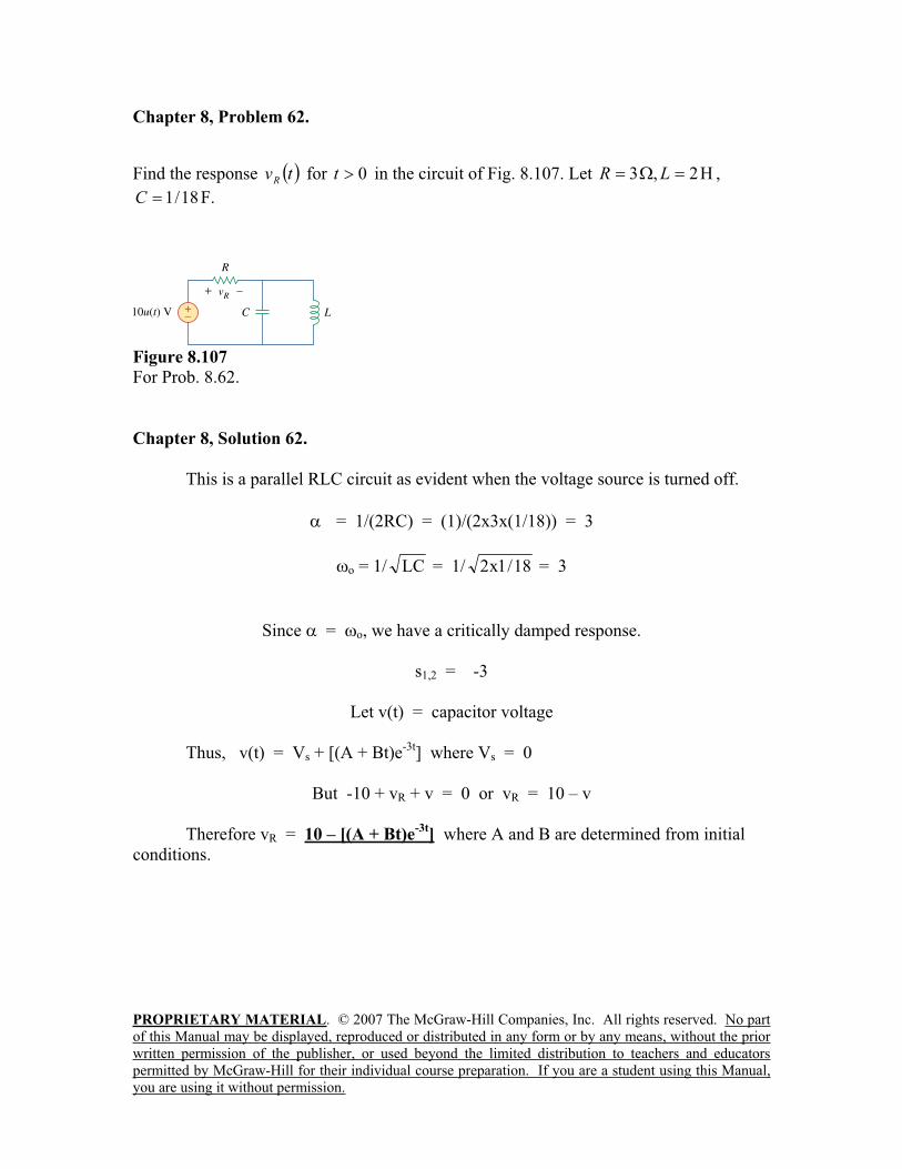
PROPRIETARY MATERIAL. © 2007 The McGraw-Hill Companies, Inc. All rights reserved. No part
of this Manual may be displayed, reproduced or distributed in any form or by any means, without the prior
written permission of the publisher, or used beyond the limited distribution to teachers and educators
permitted by McGraw-Hill for their individual course preparation. If you are a student using this Manual,
you are using it without permission.
Chapter 8, Problem 62.
Find the response tvR
for 0t in the circuit of Fig. 8.107. Let 2,3 LR ,
18/1C F.
Figure 8.107
For Prob. 8.62.
Chapter 8, Solution 62.
This is a parallel RLC circuit as evident when the voltage source is turned off.
= 1/(2RC) = (1)/(2x3x(1/18)) = 3
o = 1/ LC = 1/ 18/1x2 = 3
Since = o, we have a critically damped response.
s1,2 = -3
Let v(t) = capacitor voltage
Thus, v(t) = Vs + [(A + Bt)e-3t
] where Vs = 0
But -10 + vR + v = 0 or vR = 10 – v
Therefore vR = 10 – [(A + Bt)e-3t
] where A and B are determined from initial
conditions.
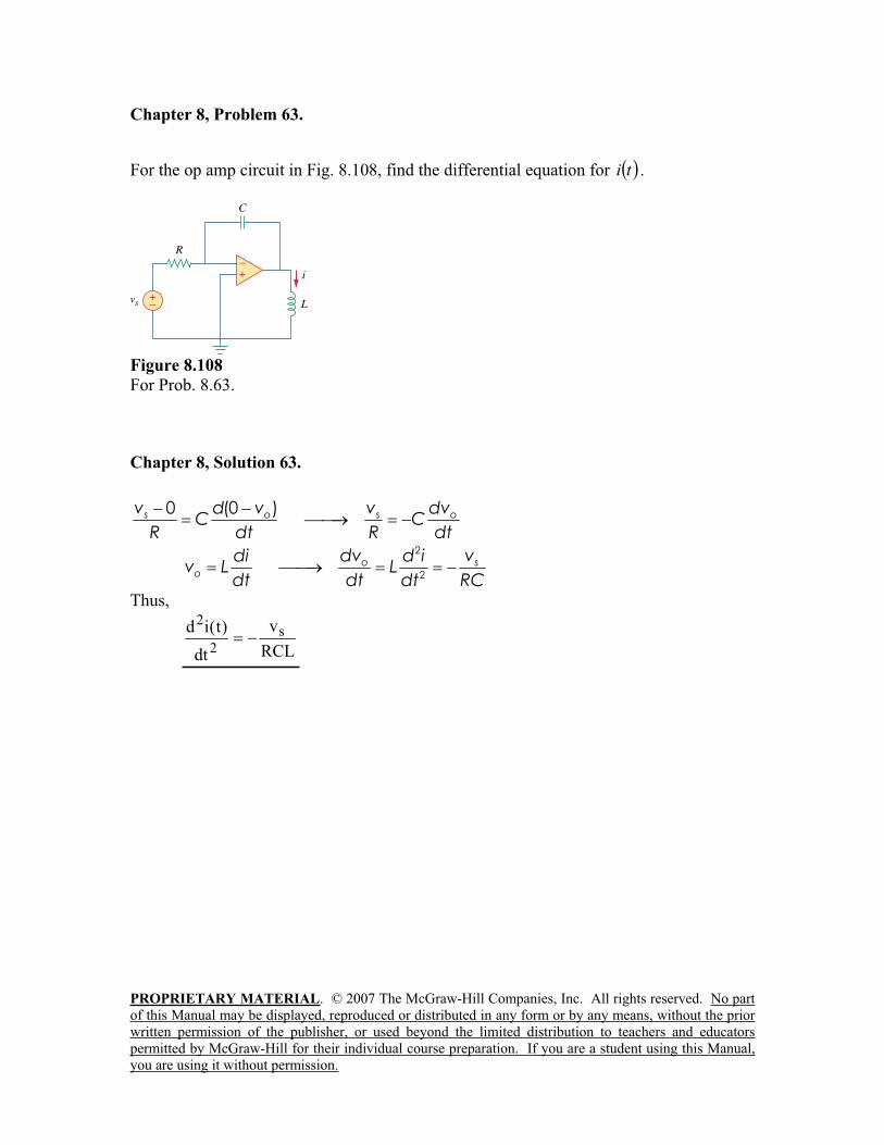
PROPRIETARY MATERIAL. © 2007 The McGraw-Hill Companies, Inc. All rights reserved. No part
of this Manual may be displayed, reproduced or distributed in any form or by any means, without the prior
written permission of the publisher, or used beyond the limited distribution to teachers and educators
permitted by McGraw-Hill for their individual course preparation. If you are a student using this Manual,
you are using it without permission.
Chapter 8, Problem 63.
For the op amp circuit in Fig. 8.108, find the differential equation for ti .
Figure 8.108
For Prob. 8.63.
Chapter 8, Solution 63.
0 (0 )s o s ov d v v dvC C
R dt R dt2
2
o so
dv vdi d iv L L
dt dt RCdtThus,
RCL
v
dt
)t(id s
2
2
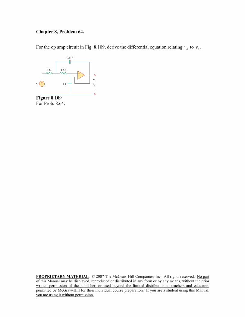
PROPRIETARY MATERIAL. © 2007 The McGraw-Hill Companies, Inc. All rights reserved. No part
of this Manual may be displayed, reproduced or distributed in any form or by any means, without the prior
written permission of the publisher, or used beyond the limited distribution to teachers and educators
permitted by McGraw-Hill for their individual course preparation. If you are a student using this Manual,
you are using it without permission.
Chapter 8, Problem 64.
For the op amp circuit in Fig. 8.109, derive the differential equation relating ov to
sv .
Figure 8.109
For Prob. 8.64.
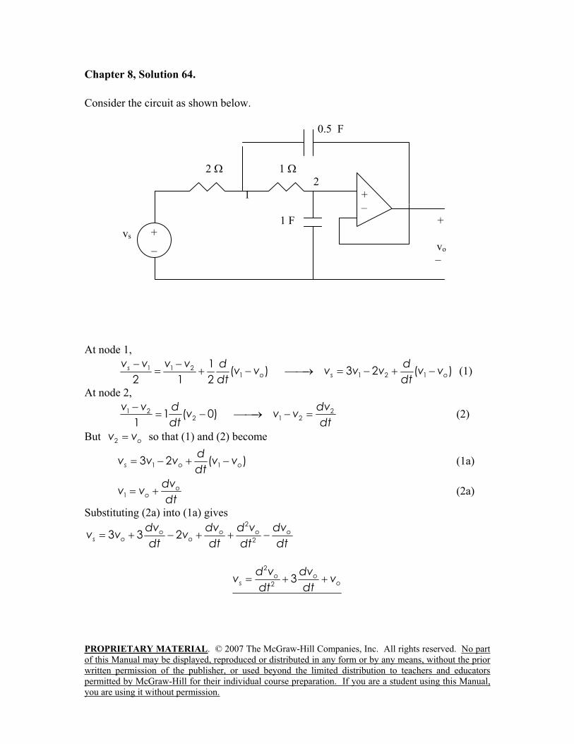
PROPRIETARY MATERIAL. © 2007 The McGraw-Hill Companies, Inc. All rights reserved. No part
of this Manual may be displayed, reproduced or distributed in any form or by any means, without the prior
written permission of the publisher, or used beyond the limited distribution to teachers and educators
permitted by McGraw-Hill for their individual course preparation. If you are a student using this Manual,
you are using it without permission.
Chapter 8, Solution 64.
Consider the circuit as shown below.
0.5 F
2 1
2
1 +
–
1 F +
vs
vo
–
At node 1,
1 1 21 1 2 1
1( ) 3 2 ( )
2 1 2s
o s o
v v v v d dv v v v v v v
dt dt (1)
At node 2,
1 2 22 1 21 ( 0)
1
v v d dvv v v
dt dt (2)
But 2 ov v so that (1) and (2) become
1 13 2 ( )s o o
dv v v v v
dt (1a)
1o
o
dvv v
dt (2a)
Substituting (2a) into (1a) gives 2
23 3 2o o o o
s o o
dv dv d v dvv v v
dt dt dtdt
2
23o o
s o
d v dvv v
dtdt
+
_
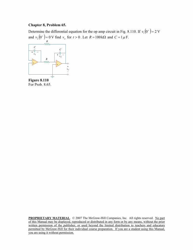
PROPRIETARY MATERIAL. © 2007 The McGraw-Hill Companies, Inc. All rights reserved. No part
of this Manual may be displayed, reproduced or distributed in any form or by any means, without the prior
written permission of the publisher, or used beyond the limited distribution to teachers and educators
permitted by McGraw-Hill for their individual course preparation. If you are a student using this Manual,
you are using it without permission.
Chapter 8, Problem 65.
Determine the differential equation for the op amp circuit in Fig. 8.110. If 201v V
and 002v V find ov for 0t . Let k100R and 1C F.
Figure 8.110
For Prob. 8.65.
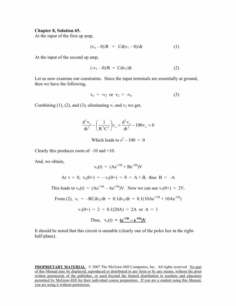
PROPRIETARY MATERIAL. © 2007 The McGraw-Hill Companies, Inc. All rights reserved. No part
of this Manual may be displayed, reproduced or distributed in any form or by any means, without the prior
written permission of the publisher, or used beyond the limited distribution to teachers and educators
permitted by McGraw-Hill for their individual course preparation. If you are a student using this Manual,
you are using it without permission.
Chapter 8, Solution 65.
At the input of the first op amp,
(vo – 0)/R = Cd(v1 – 0)/dt (1)
At the input of the second op amp,
(-v1 – 0)/R = Cdv2/dt (2)
Let us now examine our constraints. Since the input terminals are essentially at ground,
then we have the following,
vo = -v2 or v2 = -vo (3)
Combining (1), (2), and (3), eliminating v1 and v2 we get,
0v100dt
vdv
CR
1
dt
vdo2
o
2
o222
o
2
Which leads to s2 – 100 = 0
Clearly this produces roots of –10 and +10.
And, we obtain,
vo(t) = (Ae+10t
+ Be-10t
)V
At t = 0, vo(0+) = – v2(0+) = 0 = A + B, thus B = –A
This leads to vo(t) = (Ae+10t
– Ae-10t
)V. Now we can use v1(0+) = 2V.
From (2), v1 = –RCdv2/dt = 0.1dvo/dt = 0.1(10Ae+10t
+ 10Ae-10t
)
v1(0+) = 2 = 0.1(20A) = 2A or A = 1
Thus, vo(t) = (e+10t
– e-10t
)V
It should be noted that this circuit is unstable (clearly one of the poles lies in the right-
half-plane).
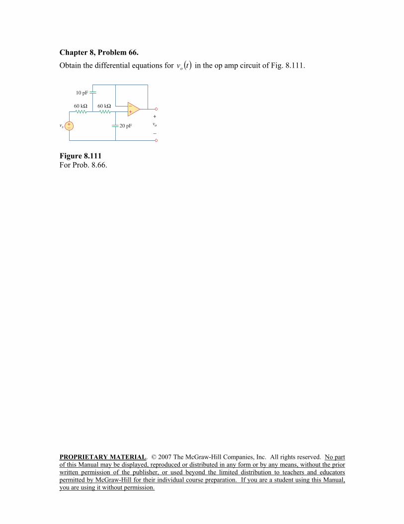
PROPRIETARY MATERIAL. © 2007 The McGraw-Hill Companies, Inc. All rights reserved. No part
of this Manual may be displayed, reproduced or distributed in any form or by any means, without the prior
written permission of the publisher, or used beyond the limited distribution to teachers and educators
permitted by McGraw-Hill for their individual course preparation. If you are a student using this Manual,
you are using it without permission.
Chapter 8, Problem 66.
Obtain the differential equations for tvo
in the op amp circuit of Fig. 8.111.
Figure 8.111
For Prob. 8.66.
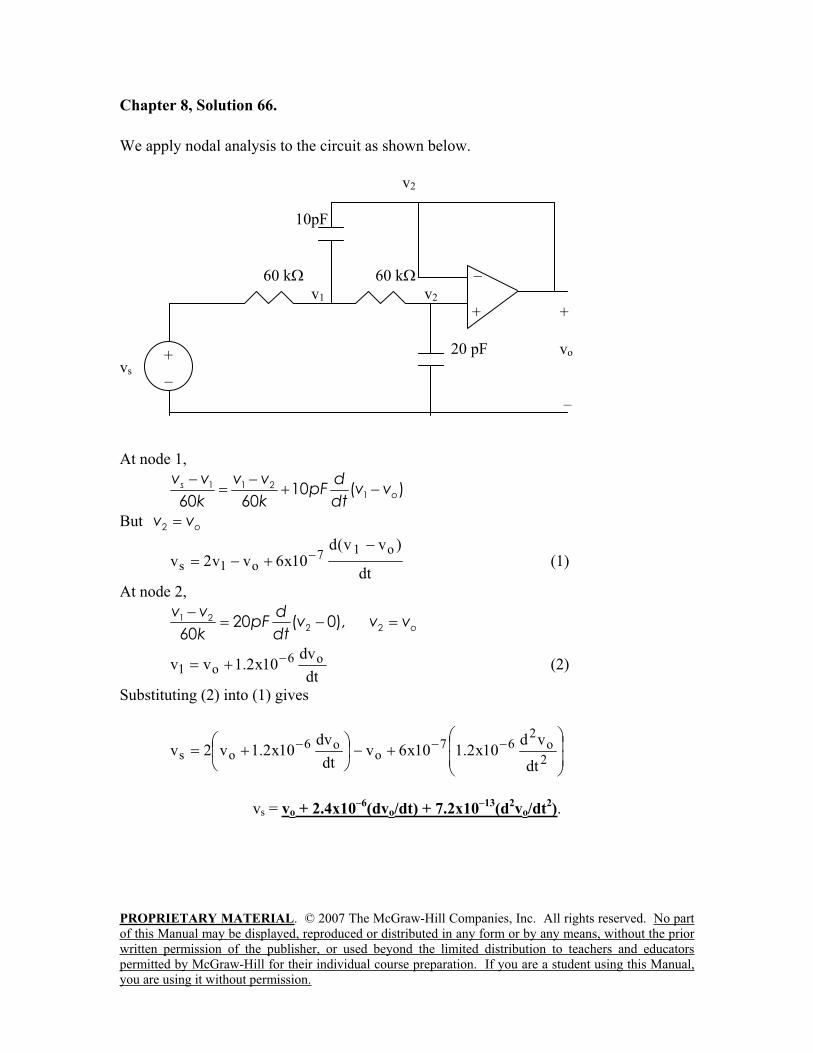
PROPRIETARY MATERIAL. © 2007 The McGraw-Hill Companies, Inc. All rights reserved. No part
of this Manual may be displayed, reproduced or distributed in any form or by any means, without the prior
written permission of the publisher, or used beyond the limited distribution to teachers and educators
permitted by McGraw-Hill for their individual course preparation. If you are a student using this Manual,
you are using it without permission.
Chapter 8, Solution 66.
We apply nodal analysis to the circuit as shown below.
v2
10pF
60 k 60 k –
v1 v2
+ +
20 pF vo
vs
–
At node 1,
1 1 2110 ( )
60 60s
o
v v v v dpF v v
k k dt
But 2 ov v
dt
)vv(d10x6vv2v
o17o1s (1)
At node 2,
1 22 220 ( 0),
60o
v v dpF v v v
k dt
dt
dv10x2.1vv o6
o1 (2)
Substituting (2) into (1) gives
2
o2
67o
o6os
dt
vd10x2.110x6v
dt
dv10x2.1v2v
vs = vo + 2.4x10⁻⁶
(dvo/dt) + 7.2x10⁻¹³
(d2vo/dt
2).
+
_
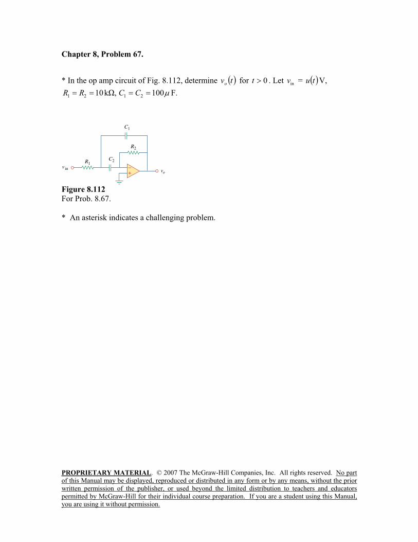
PROPRIETARY MATERIAL. © 2007 The McGraw-Hill Companies, Inc. All rights reserved. No part
of this Manual may be displayed, reproduced or distributed in any form or by any means, without the prior
written permission of the publisher, or used beyond the limited distribution to teachers and educators
permitted by McGraw-Hill for their individual course preparation. If you are a student using this Manual,
you are using it without permission.
Chapter 8, Problem 67.
* In the op amp circuit of Fig. 8.112, determine tvo
for 0t . Let inv = tu V,
100,k10 2121 CCRR F.
Figure 8.112
For Prob. 8.67.
* An asterisk indicates a challenging problem.
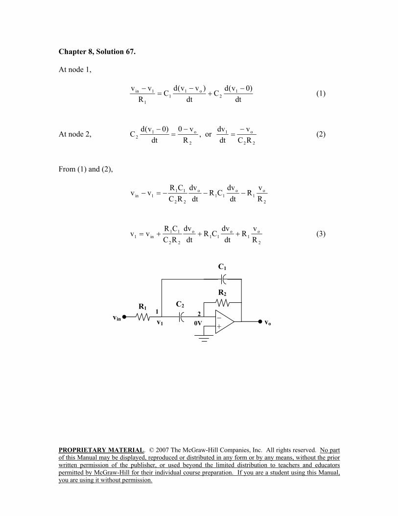
PROPRIETARY MATERIAL. © 2007 The McGraw-Hill Companies, Inc. All rights reserved. No part
of this Manual may be displayed, reproduced or distributed in any form or by any means, without the prior
written permission of the publisher, or used beyond the limited distribution to teachers and educators
permitted by McGraw-Hill for their individual course preparation. If you are a student using this Manual,
you are using it without permission.
Chapter 8, Solution 67.
At node 1,
dt
)0v(dC
dt
)vv(dC
R
vv 12
o1
1
1
1in (1)
At node 2, 2
o12
R
v0
dt
)0v(dC , or
22
o1
RC
v
dt
dv (2)
From (1) and (2),
2
o
1
o
11
o
22
111in
R
vR
dt
dvCR
dt
dv
RC
CRvv
2
o
1
o
11
o
22
11in1
R
vR
dt
dvCR
dt
dv
RC
CRvv (3)
R1
21
v1
C1
+
R2
C2
vinvo0V
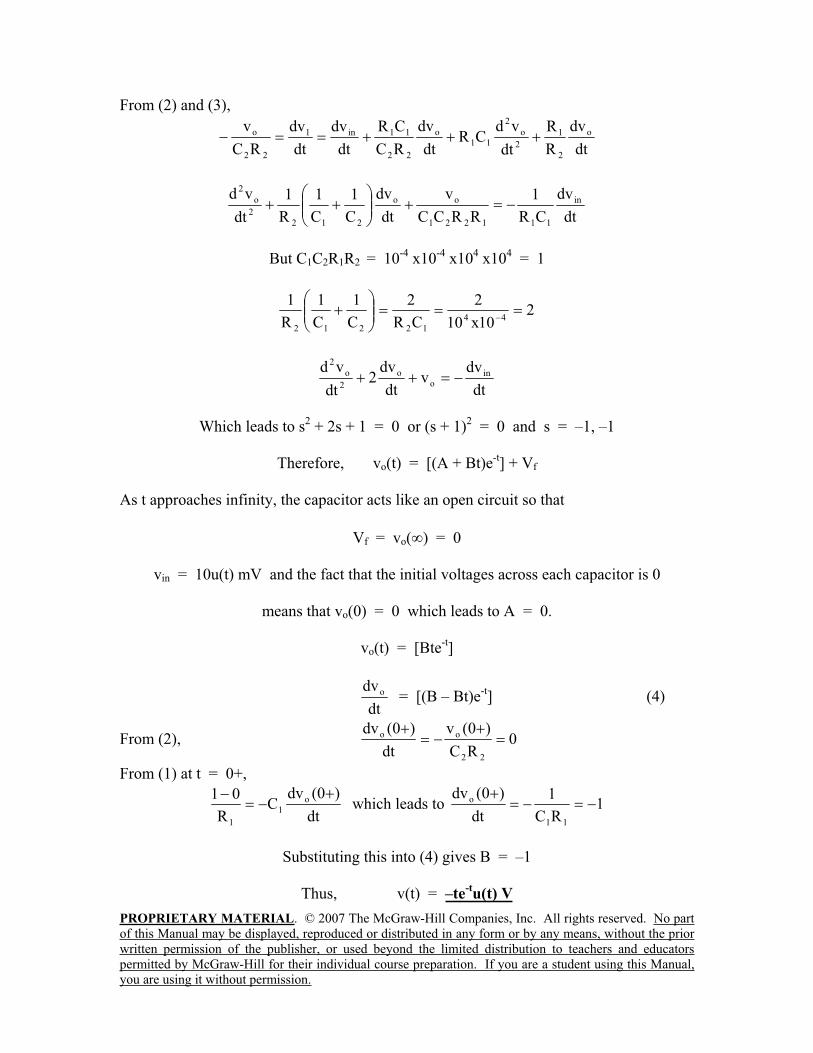
PROPRIETARY MATERIAL. © 2007 The McGraw-Hill Companies, Inc. All rights reserved. No part
of this Manual may be displayed, reproduced or distributed in any form or by any means, without the prior
written permission of the publisher, or used beyond the limited distribution to teachers and educators
permitted by McGraw-Hill for their individual course preparation. If you are a student using this Manual,
you are using it without permission.
From (2) and (3),
dt
dv
R
R
dt
vdCR
dt
dv
RC
CR
dt
dv
dt
dv
RC
v o
2
1
2
o
2
11
o
22
11in1
22
o
dt
dv
CR
1
RRCC
v
dt
dv
C
1
C
1
R
1
dt
vd in
111221
oo
212
2
o
2
But C1C2R1R2 = 10-4
x10-4
x104 x10
4 = 1
210x10
2
CR
2
C
1
C
1
R
144
12212
dt
dvv
dt
dv2
dt
vd ino
o
2
o
2
Which leads to s2 + 2s + 1 = 0 or (s + 1)
2 = 0 and s = –1, –1
Therefore, vo(t) = [(A + Bt)e-t] + Vf
As t approaches infinity, the capacitor acts like an open circuit so that
Vf = vo( ) = 0
vin = 10u(t) mV and the fact that the initial voltages across each capacitor is 0
means that vo(0) = 0 which leads to A = 0.
vo(t) = [Bte-t]
dt
dvo = [(B – Bt)e-t] (4)
From (2), 0RC
)0(v
dt
)0(dv
22
oo
From (1) at t = 0+,
dt
)0(dvC
R
01 o
1
1
which leads to 1RC
1
dt
)0(dv
11
o
Substituting this into (4) gives B = –1
Thus, v(t) = –te-tu(t) V
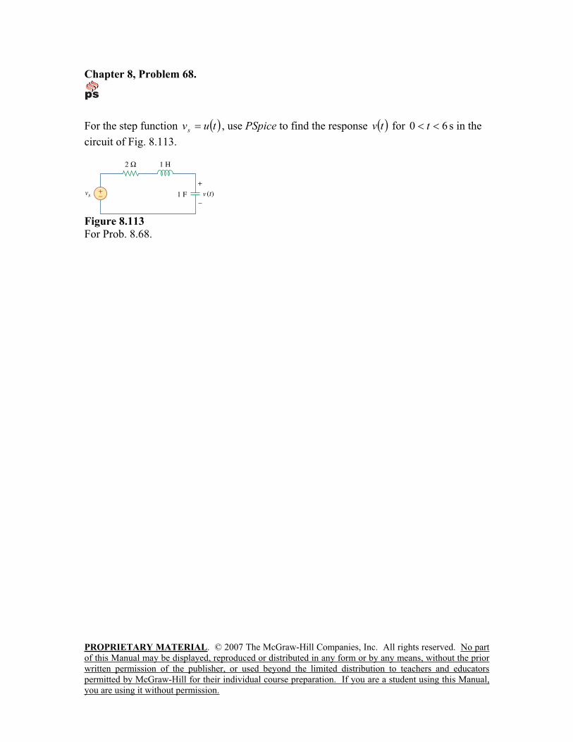
PROPRIETARY MATERIAL. © 2007 The McGraw-Hill Companies, Inc. All rights reserved. No part
of this Manual may be displayed, reproduced or distributed in any form or by any means, without the prior
written permission of the publisher, or used beyond the limited distribution to teachers and educators
permitted by McGraw-Hill for their individual course preparation. If you are a student using this Manual,
you are using it without permission.
Chapter 8, Problem 68.
For the step function tuvs
, use PSpice to find the response tv for 60 t s in the
circuit of Fig. 8.113.
Figure 8.113
For Prob. 8.68.
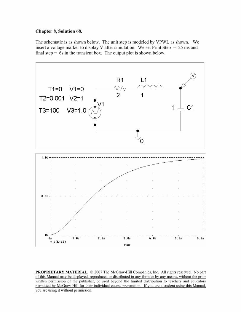
PROPRIETARY MATERIAL. © 2007 The McGraw-Hill Companies, Inc. All rights reserved. No part
of this Manual may be displayed, reproduced or distributed in any form or by any means, without the prior
written permission of the publisher, or used beyond the limited distribution to teachers and educators
permitted by McGraw-Hill for their individual course preparation. If you are a student using this Manual,
you are using it without permission.
Chapter 8, Solution 68.
The schematic is as shown below. The unit step is modeled by VPWL as shown. We
insert a voltage marker to display V after simulation. We set Print Step = 25 ms and
final step = 6s in the transient box. The output plot is shown below.
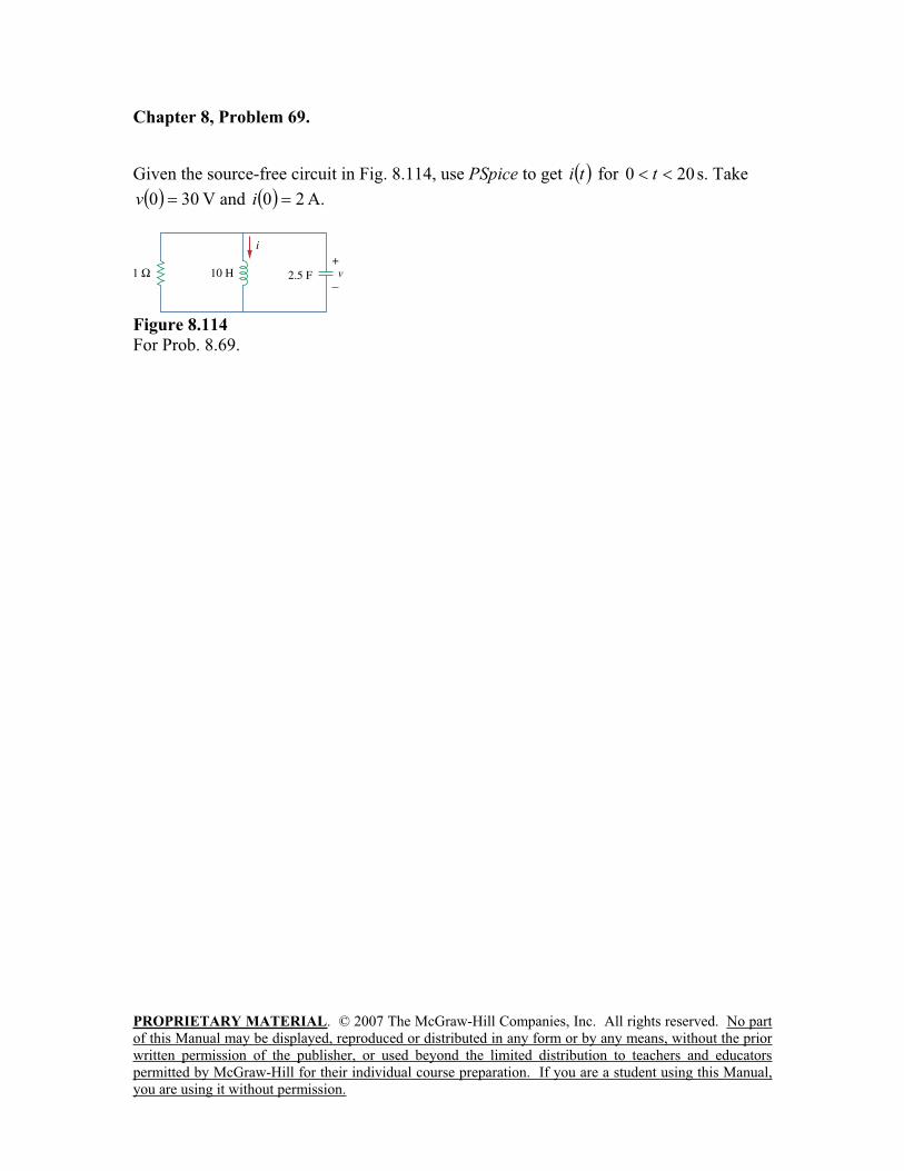
PROPRIETARY MATERIAL. © 2007 The McGraw-Hill Companies, Inc. All rights reserved. No part
of this Manual may be displayed, reproduced or distributed in any form or by any means, without the prior
written permission of the publisher, or used beyond the limited distribution to teachers and educators
permitted by McGraw-Hill for their individual course preparation. If you are a student using this Manual,
you are using it without permission.
Chapter 8, Problem 69.
Given the source-free circuit in Fig. 8.114, use PSpice to get ti for 200 t s. Take
300v V and 20i A.
Figure 8.114
For Prob. 8.69.
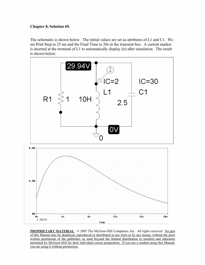
PROPRIETARY MATERIAL. © 2007 The McGraw-Hill Companies, Inc. All rights reserved. No part
of this Manual may be displayed, reproduced or distributed in any form or by any means, without the prior
written permission of the publisher, or used beyond the limited distribution to teachers and educators
permitted by McGraw-Hill for their individual course preparation. If you are a student using this Manual,
you are using it without permission.
Chapter 8, Solution 69.
The schematic is shown below. The initial values are set as attributes of L1 and C1. We
set Print Step to 25 ms and the Final Time to 20s in the transient box. A current marker
is inserted at the terminal of L1 to automatically display i(t) after simulation. The result
is shown below.
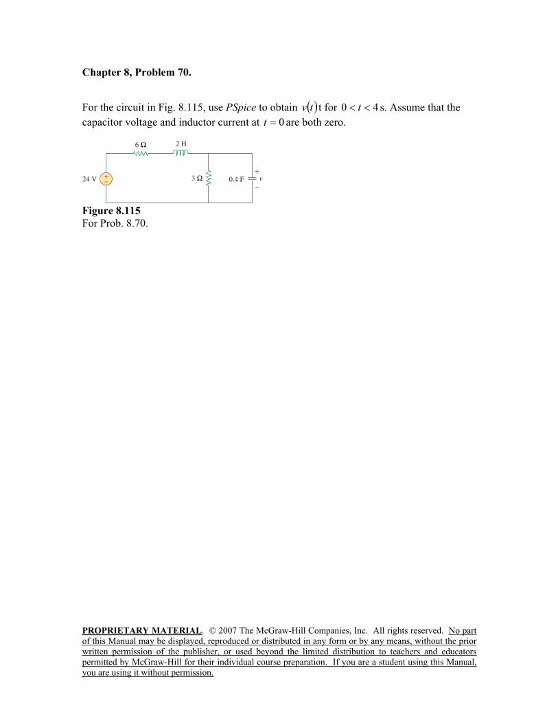
PROPRIETARY MATERIAL. © 2007 The McGraw-Hill Companies, Inc. All rights reserved. No part
of this Manual may be displayed, reproduced or distributed in any form or by any means, without the prior
written permission of the publisher, or used beyond the limited distribution to teachers and educators
permitted by McGraw-Hill for their individual course preparation. If you are a student using this Manual,
you are using it without permission.
Chapter 8, Problem 70.
For the circuit in Fig. 8.115, use PSpice to obtain tv t for 40 t s. Assume that the
capacitor voltage and inductor current at 0t are both zero.
Figure 8.115
For Prob. 8.70.
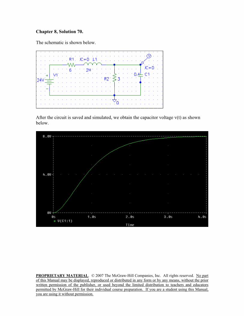
PROPRIETARY MATERIAL. © 2007 The McGraw-Hill Companies, Inc. All rights reserved. No part
of this Manual may be displayed, reproduced or distributed in any form or by any means, without the prior
written permission of the publisher, or used beyond the limited distribution to teachers and educators
permitted by McGraw-Hill for their individual course preparation. If you are a student using this Manual,
you are using it without permission.
Chapter 8, Solution 70.
The schematic is shown below.
After the circuit is saved and simulated, we obtain the capacitor voltage v(t) as shown
below.
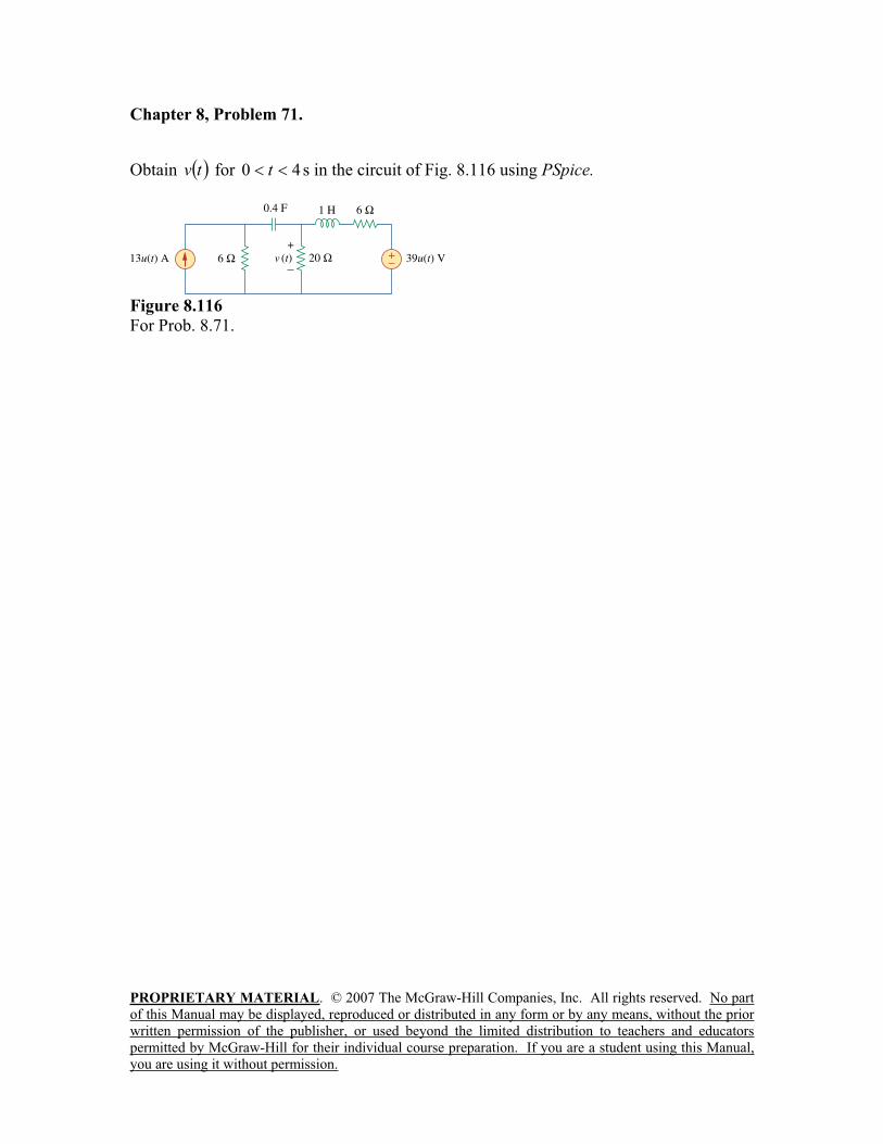
PROPRIETARY MATERIAL. © 2007 The McGraw-Hill Companies, Inc. All rights reserved. No part
of this Manual may be displayed, reproduced or distributed in any form or by any means, without the prior
written permission of the publisher, or used beyond the limited distribution to teachers and educators
permitted by McGraw-Hill for their individual course preparation. If you are a student using this Manual,
you are using it without permission.
Chapter 8, Problem 71.
Obtain tv for 40 t s in the circuit of Fig. 8.116 using PSpice.
Figure 8.116
For Prob. 8.71.
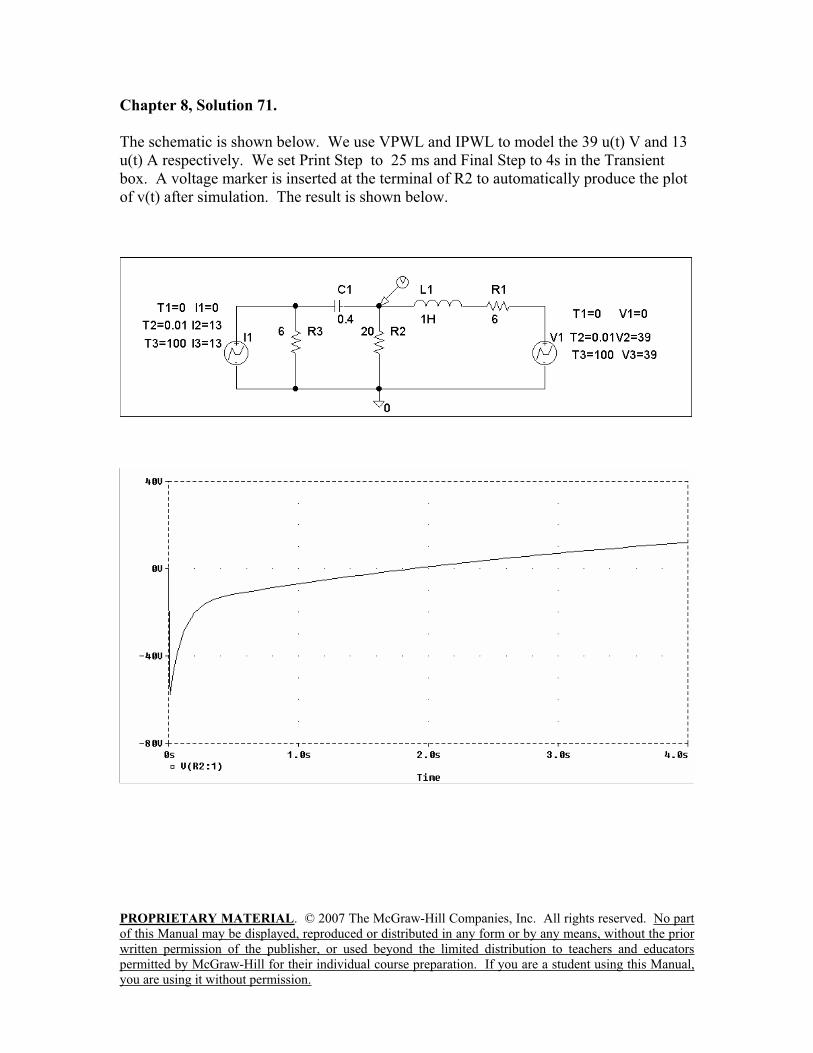
PROPRIETARY MATERIAL. © 2007 The McGraw-Hill Companies, Inc. All rights reserved. No part
of this Manual may be displayed, reproduced or distributed in any form or by any means, without the prior
written permission of the publisher, or used beyond the limited distribution to teachers and educators
permitted by McGraw-Hill for their individual course preparation. If you are a student using this Manual,
you are using it without permission.
Chapter 8, Solution 71.
The schematic is shown below. We use VPWL and IPWL to model the 39 u(t) V and 13
u(t) A respectively. We set Print Step to 25 ms and Final Step to 4s in the Transient
box. A voltage marker is inserted at the terminal of R2 to automatically produce the plot
of v(t) after simulation. The result is shown below.

PROPRIETARY MATERIAL. © 2007 The McGraw-Hill Companies, Inc. All rights reserved. No part
of this Manual may be displayed, reproduced or distributed in any form or by any means, without the prior
written permission of the publisher, or used beyond the limited distribution to teachers and educators
permitted by McGraw-Hill for their individual course preparation. If you are a student using this Manual,
you are using it without permission.
Chapter 8, Problem 72.
The switch in Fig. 8.117 has been in position 1 for a long time. At 0t , it is switched to
position 2. Use PSpice to find ti for 2.00 t s.
Figure 8.117
For Prob. 8.72.
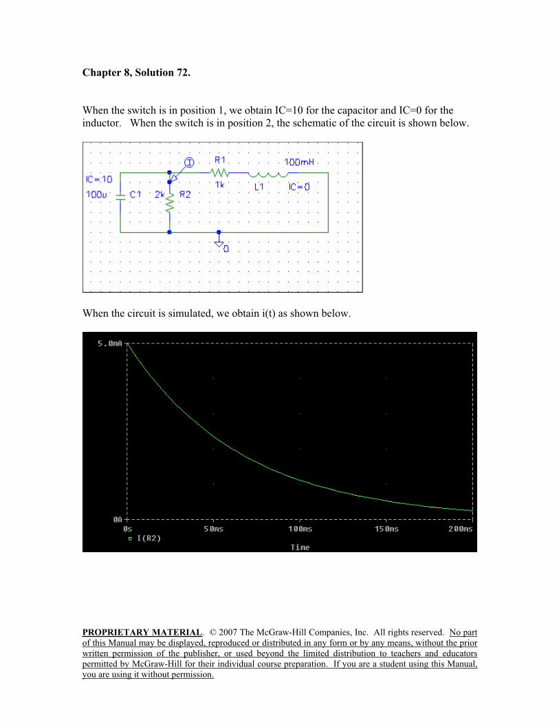
PROPRIETARY MATERIAL. © 2007 The McGraw-Hill Companies, Inc. All rights reserved. No part
of this Manual may be displayed, reproduced or distributed in any form or by any means, without the prior
written permission of the publisher, or used beyond the limited distribution to teachers and educators
permitted by McGraw-Hill for their individual course preparation. If you are a student using this Manual,
you are using it without permission.
Chapter 8, Solution 72.
When the switch is in position 1, we obtain IC=10 for the capacitor and IC=0 for the
inductor. When the switch is in position 2, the schematic of the circuit is shown below.
When the circuit is simulated, we obtain i(t) as shown below.
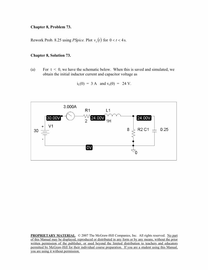
PROPRIETARY MATERIAL. © 2007 The McGraw-Hill Companies, Inc. All rights reserved. No part
of this Manual may be displayed, reproduced or distributed in any form or by any means, without the prior
written permission of the publisher, or used beyond the limited distribution to teachers and educators
permitted by McGraw-Hill for their individual course preparation. If you are a student using this Manual,
you are using it without permission.
Chapter 8, Problem 73.
Rework Prob. 8.25 using PSpice. Plot tvo
for 40 t s.
Chapter 8, Solution 73.
(a) For t < 0, we have the schematic below. When this is saved and simulated, we
obtain the initial inductor current and capacitor voltage as
iL(0) = 3 A and vc(0) = 24 V.
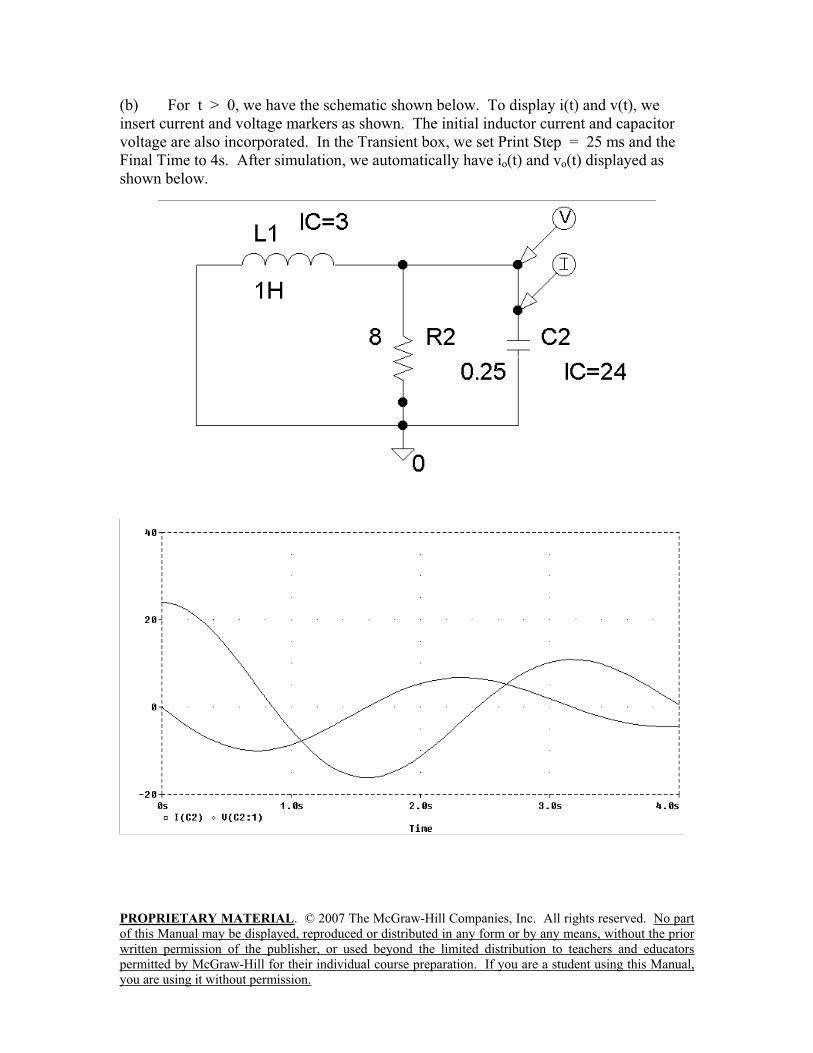
PROPRIETARY MATERIAL. © 2007 The McGraw-Hill Companies, Inc. All rights reserved. No part
of this Manual may be displayed, reproduced or distributed in any form or by any means, without the prior
written permission of the publisher, or used beyond the limited distribution to teachers and educators
permitted by McGraw-Hill for their individual course preparation. If you are a student using this Manual,
you are using it without permission.
(b) For t > 0, we have the schematic shown below. To display i(t) and v(t), we
insert current and voltage markers as shown. The initial inductor current and capacitor
voltage are also incorporated. In the Transient box, we set Print Step = 25 ms and the
Final Time to 4s. After simulation, we automatically have io(t) and vo(t) displayed as
shown below.
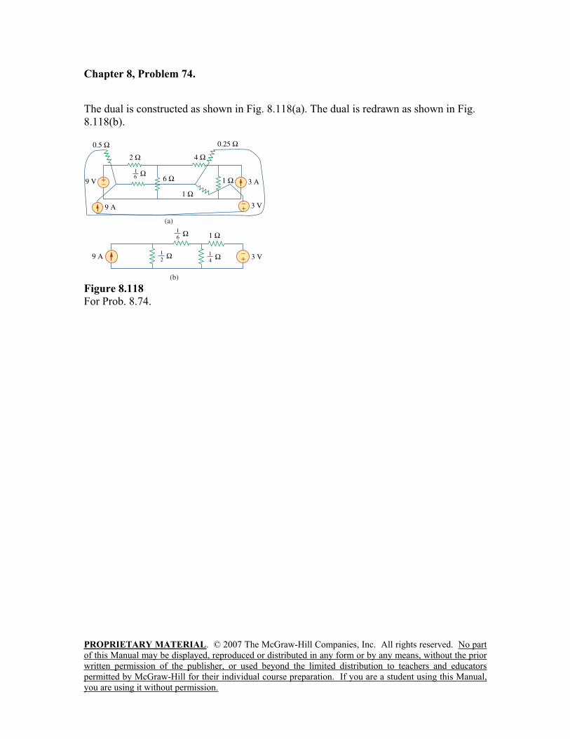
PROPRIETARY MATERIAL. © 2007 The McGraw-Hill Companies, Inc. All rights reserved. No part
of this Manual may be displayed, reproduced or distributed in any form or by any means, without the prior
written permission of the publisher, or used beyond the limited distribution to teachers and educators
permitted by McGraw-Hill for their individual course preparation. If you are a student using this Manual,
you are using it without permission.
Chapter 8, Problem 74.
The dual is constructed as shown in Fig. 8.118(a). The dual is redrawn as shown in Fig.
8.118(b).
Figure 8.118
For Prob. 8.74.
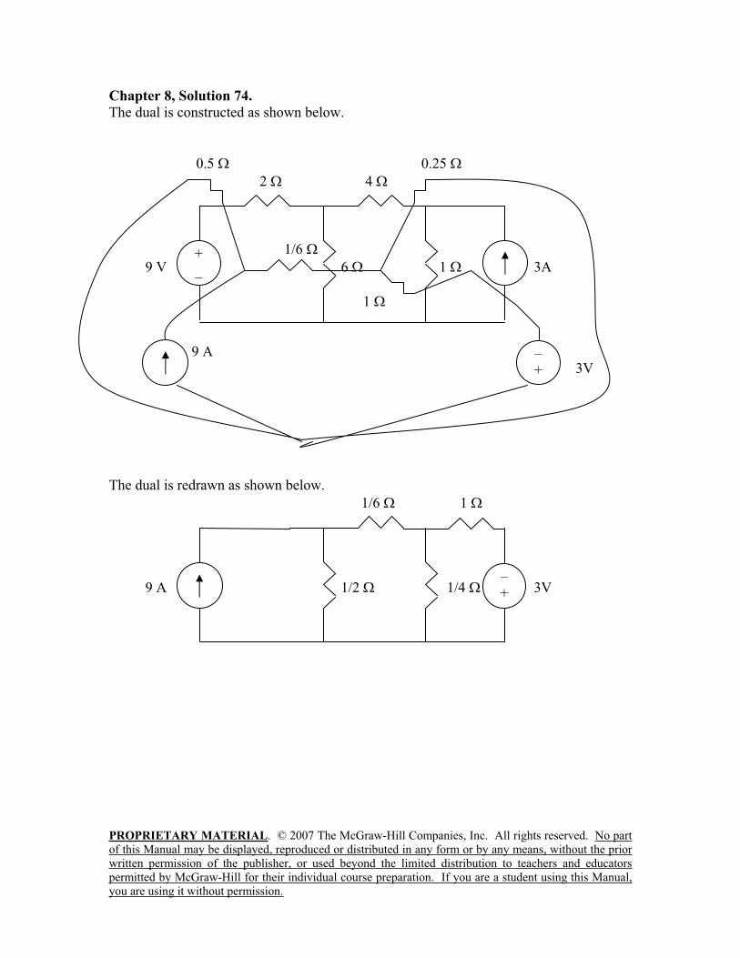
PROPRIETARY MATERIAL. © 2007 The McGraw-Hill Companies, Inc. All rights reserved. No part
of this Manual may be displayed, reproduced or distributed in any form or by any means, without the prior
written permission of the publisher, or used beyond the limited distribution to teachers and educators
permitted by McGraw-Hill for their individual course preparation. If you are a student using this Manual,
you are using it without permission.
Chapter 8, Solution 74.
The dual is constructed as shown below.
0.5 0.25
2 4
1/6
9 V 6 1 3A
1
9 A
3V
The dual is redrawn as shown below.
1/6 1
9 A 1/2 1/4 3V
+
_
–
+
–
+
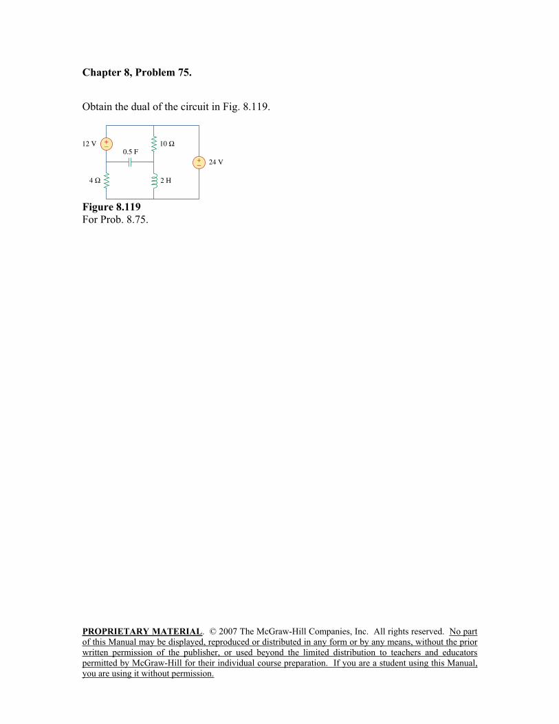
PROPRIETARY MATERIAL. © 2007 The McGraw-Hill Companies, Inc. All rights reserved. No part
of this Manual may be displayed, reproduced or distributed in any form or by any means, without the prior
written permission of the publisher, or used beyond the limited distribution to teachers and educators
permitted by McGraw-Hill for their individual course preparation. If you are a student using this Manual,
you are using it without permission.
Chapter 8, Problem 75.
Obtain the dual of the circuit in Fig. 8.119.
Figure 8.119
For Prob. 8.75.
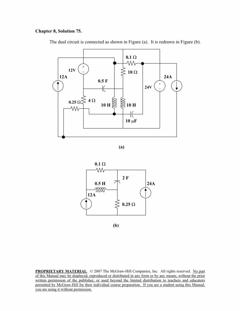
PROPRIETARY MATERIAL. © 2007 The McGraw-Hill Companies, Inc. All rights reserved. No part
of this Manual may be displayed, reproduced or distributed in any form or by any means, without the prior
written permission of the publisher, or used beyond the limited distribution to teachers and educators
permitted by McGraw-Hill for their individual course preparation. If you are a student using this Manual,
you are using it without permission.
Chapter 8, Solution 75.
The dual circuit is connected as shown in Figure (a). It is redrawn in Figure (b).
0.1
4
(a)
10 H
0.5 F
12V+
24A
0.25
10
10 H
24V+
12A
10 F
0.1
0.25
(b)
24A
12A
2 F
0.5 H
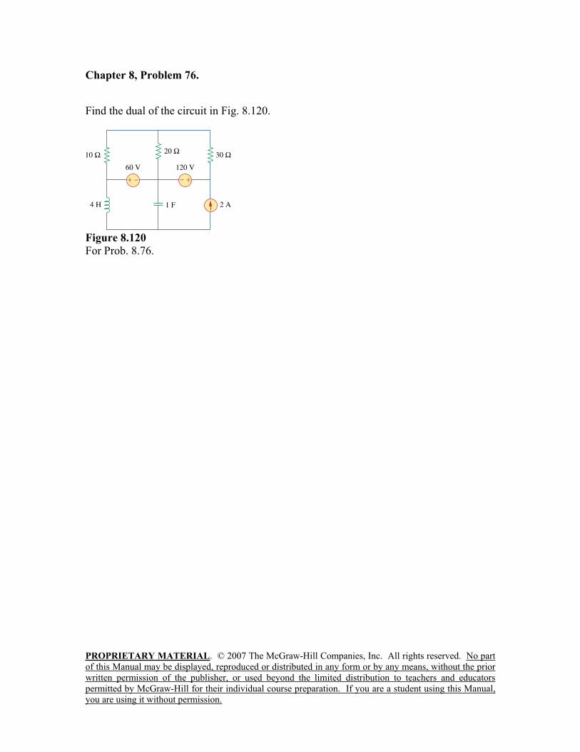
PROPRIETARY MATERIAL. © 2007 The McGraw-Hill Companies, Inc. All rights reserved. No part
of this Manual may be displayed, reproduced or distributed in any form or by any means, without the prior
written permission of the publisher, or used beyond the limited distribution to teachers and educators
permitted by McGraw-Hill for their individual course preparation. If you are a student using this Manual,
you are using it without permission.
Chapter 8, Problem 76.
Find the dual of the circuit in Fig. 8.120.
Figure 8.120
For Prob. 8.76.
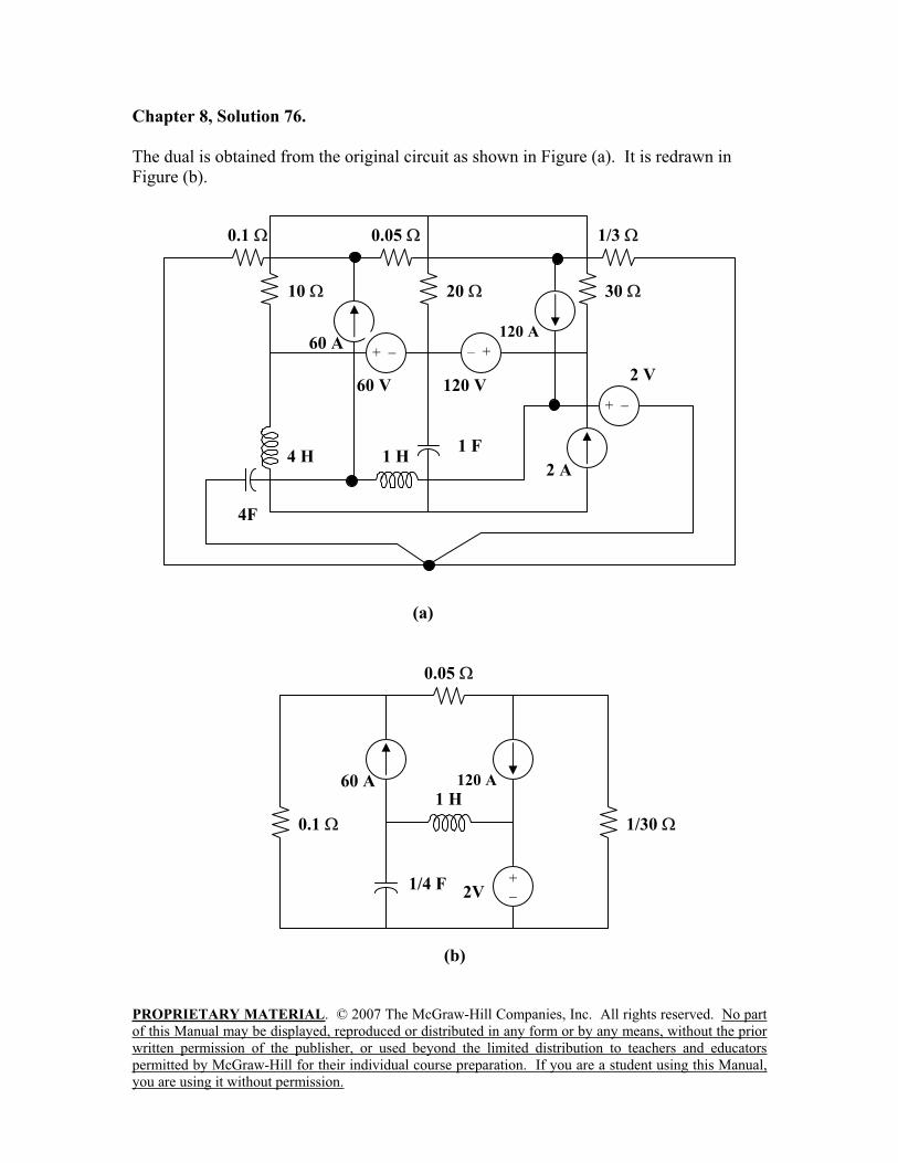
PROPRIETARY MATERIAL. © 2007 The McGraw-Hill Companies, Inc. All rights reserved. No part
of this Manual may be displayed, reproduced or distributed in any form or by any means, without the prior
written permission of the publisher, or used beyond the limited distribution to teachers and educators
permitted by McGraw-Hill for their individual course preparation. If you are a student using this Manual,
you are using it without permission.
Chapter 8, Solution 76.
The dual is obtained from the original circuit as shown in Figure (a). It is redrawn in
Figure (b).
(b)
2V+
1/30
0.05
0.1
1/4 F
1 H 60 A 120 A
0.05
20
(a)
1 H 4 H 1 F
4F
60 A +
60 V
– +
120 V
0.1
10
1/3
30
2 A
+
2 V
120 A
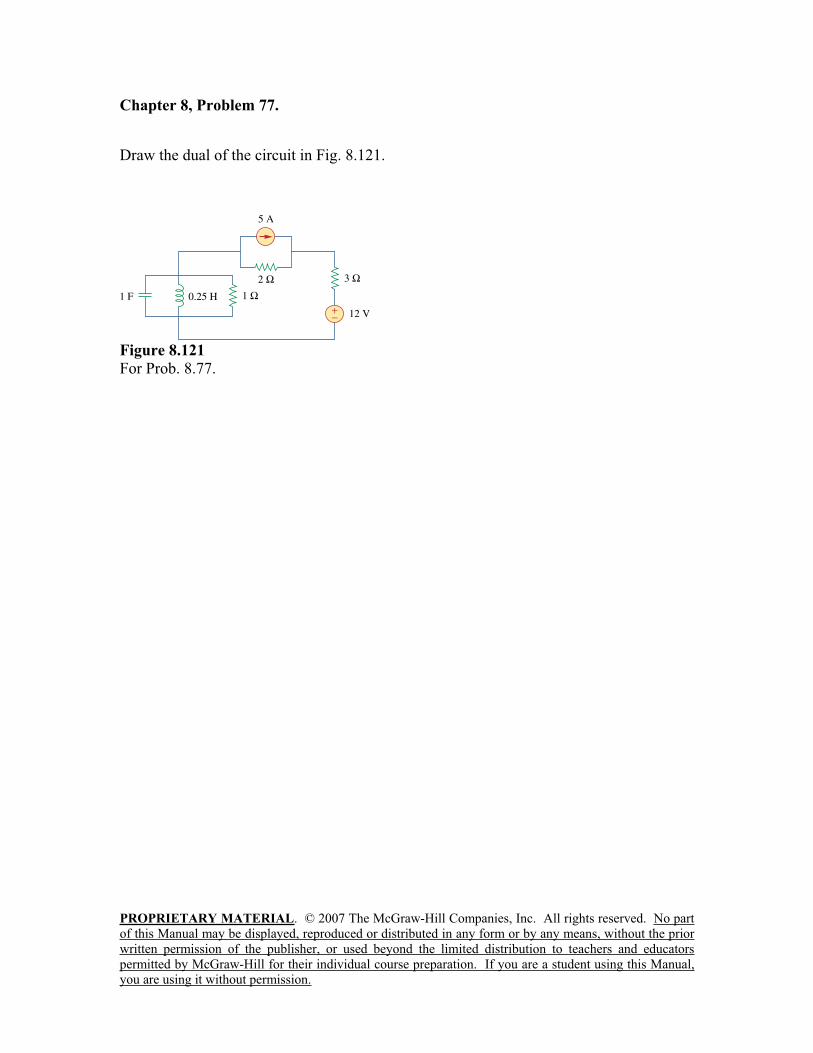
PROPRIETARY MATERIAL. © 2007 The McGraw-Hill Companies, Inc. All rights reserved. No part
of this Manual may be displayed, reproduced or distributed in any form or by any means, without the prior
written permission of the publisher, or used beyond the limited distribution to teachers and educators
permitted by McGraw-Hill for their individual course preparation. If you are a student using this Manual,
you are using it without permission.
Chapter 8, Problem 77.
Draw the dual of the circuit in Fig. 8.121.
Figure 8.121
For Prob. 8.77.
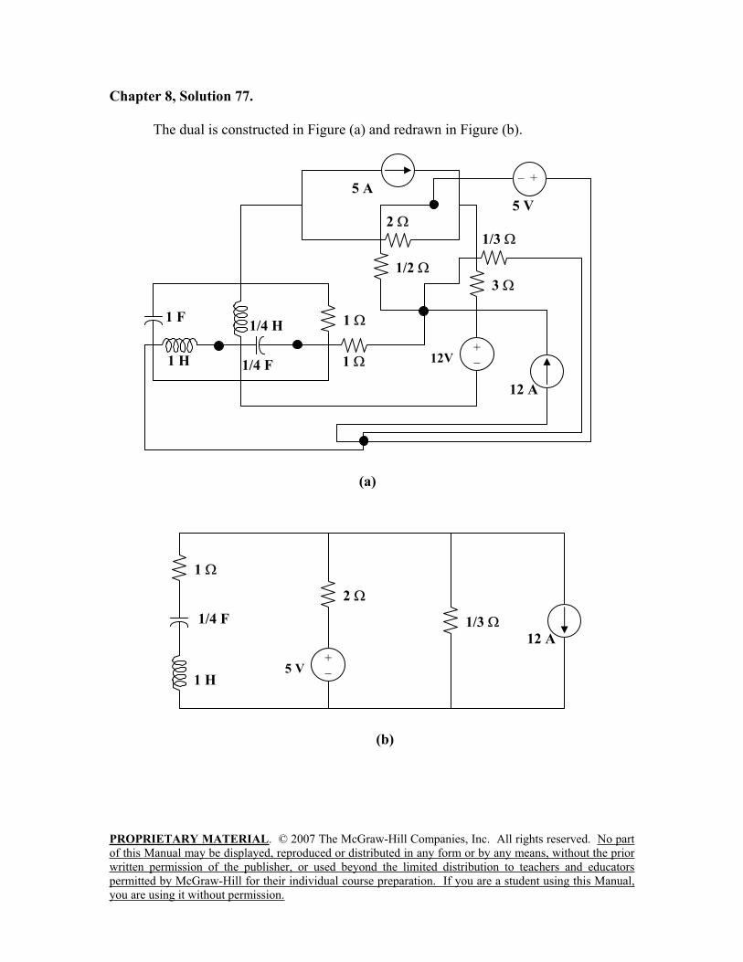
PROPRIETARY MATERIAL. © 2007 The McGraw-Hill Companies, Inc. All rights reserved. No part
of this Manual may be displayed, reproduced or distributed in any form or by any means, without the prior
written permission of the publisher, or used beyond the limited distribution to teachers and educators
permitted by McGraw-Hill for their individual course preparation. If you are a student using this Manual,
you are using it without permission.
Chapter 8, Solution 77.
The dual is constructed in Figure (a) and redrawn in Figure (b).
2
1
(a)
1 H
1/4 H 1 F
1/4 F 12V
+
5 A – +
5 V
1/2
3
1/3
12 A
1
12 A
(b)
1/3
1
2
1 H
1/4 F
5 V+
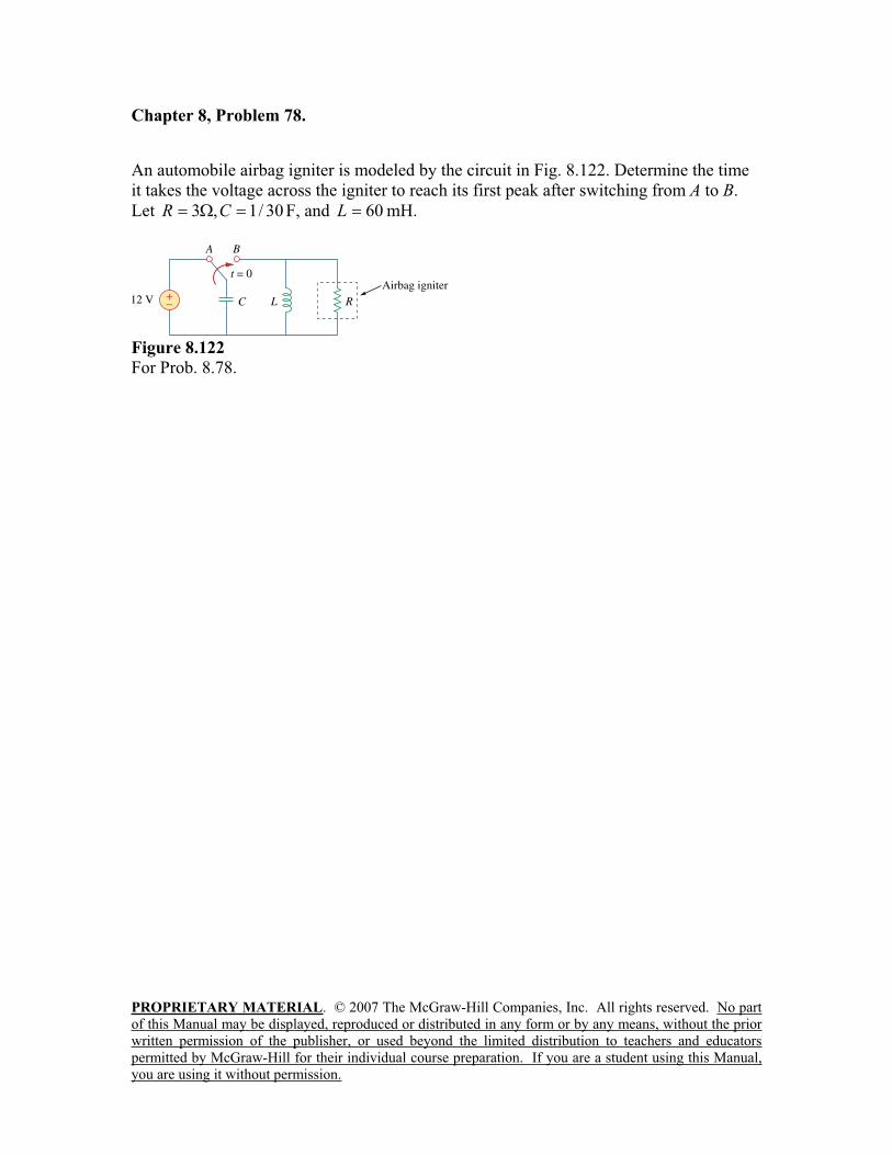
PROPRIETARY MATERIAL. © 2007 The McGraw-Hill Companies, Inc. All rights reserved. No part
of this Manual may be displayed, reproduced or distributed in any form or by any means, without the prior
written permission of the publisher, or used beyond the limited distribution to teachers and educators
permitted by McGraw-Hill for their individual course preparation. If you are a student using this Manual,
you are using it without permission.
Chapter 8, Problem 78.
An automobile airbag igniter is modeled by the circuit in Fig. 8.122. Determine the time
it takes the voltage across the igniter to reach its first peak after switching from A to B.
Let 30/1,3 CR F, and 60L mH.
Figure 8.122
For Prob. 8.78.
PROPRIETARY MATERIAL. © 2007 The McGraw-Hill Companies, Inc. All rights reserved. No part
of this Manual may be displayed, reproduced or distributed in any form or by any means, without the prior
written permission of the publisher, or used beyond the limited distribution to teachers and educators
permitted by McGraw-Hill for their individual course preparation. If you are a student using this Manual,
you are using it without permission.
Chapter 8, Solution 78.
The voltage across the igniter is vR = vC since the circuit is a parallel RLC type.
vC(0) = 12, and iL(0) = 0.
= 1/(2RC) = 1/(2x3x1/30) = 5
o 30/1x10x60/1LC/1 3 = 22.36
< o produces an underdamped response.
2
o
2
2,1s = –5 j21.794
vC(t) = e-5t
(Acos21.794t + Bsin21.794t) (1)
vC(0) = 12 = A
dvC/dt = –5[(Acos21.794t + Bsin21.794t)e-5t
]
+ 21.794[(–Asin21.794t + Bcos21.794t)e-5t
] (2)
dvC(0)/dt = –5A + 21.794B
But, dvC(0)/dt = –[vC(0) + RiL(0)]/(RC) = –(12 + 0)/(1/10) = –120
Hence, –120 = –5A + 21.794B, leads to B (5x12 – 120)/21.794 = –2.753
At the peak value, dvC(to)/dt = 0, i.e.,
0 = A + Btan21.794to + (A21.794/5)tan21.794to – 21.794B/5
(B + A21.794/5)tan21.794to = (21.794B/5) – A
tan21.794to = [(21.794B/5) – A]/(B + A21.794/5) = –24/49.55 = –0.484
Therefore, 21.7945to = |–0.451|
to = |–0.451|/21.794 = 20.68 ms
PROPRIETARY MATERIAL. © 2007 The McGraw-Hill Companies, Inc. All rights reserved. No part
of this Manual may be displayed, reproduced or distributed in any form or by any means, without the prior
written permission of the publisher, or used beyond the limited distribution to teachers and educators
permitted by McGraw-Hill for their individual course preparation. If you are a student using this Manual,
you are using it without permission.
Chapter 8, Problem 79.
A load is modeled as a 250-mH inductor in parallel with a 12- resistor. A capacitor is
needed to be connected to the load so that the network is critically damped at 60 Hz.
Calculate the size of the capacitor.
Chapter 8, Solution 79.
For critical damping of a parallel RLC circuit,
LCRCo
1
2
1
Hence,
F4341444
25.0
4 2xR
LC
PROPRIETARY MATERIAL. © 2007 The McGraw-Hill Companies, Inc. All rights reserved. No part
of this Manual may be displayed, reproduced or distributed in any form or by any means, without the prior
written permission of the publisher, or used beyond the limited distribution to teachers and educators
permitted by McGraw-Hill for their individual course preparation. If you are a student using this Manual,
you are using it without permission.
Chapter 8, Problem 80.
A mechanical system is modeled by a series RLC circuit. It is desired to produce an
overdamped response with time constants 0.1 ms and 0.5 ms. If a series 50-k resistor is
used, find the values of L and C.
Chapter 8, Solution 80.
t1 = 1/|s1| = 0.1x10⁻³
leads to s1 = –1000/0.1 = –10,000
t2 = 1/|s2| = 0.5x10⁻³
leads to s1 = –2,000
2
o
2
1s
2
o
2
2s
s1 + s2 = –2 = –12,000, therefore = 6,000 = R/(2L)
L = R/12,000 = 50,000/12,000 = 4.167H
2
o
2
2s = –2,000
2
o
2 = 2,000
2
o
2000,6 = 2,000
2
o
2 = 4,000
2 – 2
o = 16x106
2
o =2 – 16x10
6 = 36x10
6 – 16x10
6
o = 103 LC/120
C = 1/(20x106x4.167) = 12 nF
PROPRIETARY MATERIAL. © 2007 The McGraw-Hill Companies, Inc. All rights reserved. No part
of this Manual may be displayed, reproduced or distributed in any form or by any means, without the prior
written permission of the publisher, or used beyond the limited distribution to teachers and educators
permitted by McGraw-Hill for their individual course preparation. If you are a student using this Manual,
you are using it without permission.
Chapter 8, Problem 81.
An oscillogram can be adequately modeled by a second-order system in the form of a
parallel RLC circuit. It is desired to give an underdamped voltage across a 200-
resistor. If the damping frequency is 4 kHz and the time constant of the envelope is 0.25
s, find the necessary values of L and C.
Chapter 8, Solution 81.
t = 1/ = 0.25 leads to = 4
But, 1/(2RC) or, C = 1/(2 R) = 1/(2x4x200) = 625 F
22
od
232322
d
2
o 010x42(16)10x42( = 1/(LC)
This results in L = 1/(642x10
6x625x10
-6) = 2.533 H
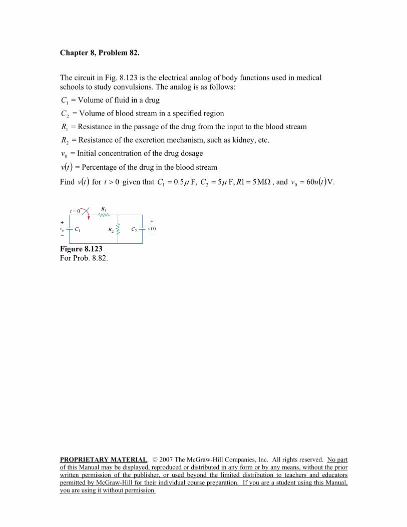
PROPRIETARY MATERIAL. © 2007 The McGraw-Hill Companies, Inc. All rights reserved. No part
of this Manual may be displayed, reproduced or distributed in any form or by any means, without the prior
written permission of the publisher, or used beyond the limited distribution to teachers and educators
permitted by McGraw-Hill for their individual course preparation. If you are a student using this Manual,
you are using it without permission.
Chapter 8, Problem 82.
The circuit in Fig. 8.123 is the electrical analog of body functions used in medical
schools to study convulsions. The analog is as follows:
1C = Volume of fluid in a drug
2C = Volume of blood stream in a specified region
1R = Resistance in the passage of the drug from the input to the blood stream
2R = Resistance of the excretion mechanism, such as kidney, etc.
0v = Initial concentration of the drug dosage
tv = Percentage of the drug in the blood stream
Find tv for 0t given that 5.01C F, 52C F, 51R , and tuv 600 V.
Figure 8.123
For Prob. 8.82.
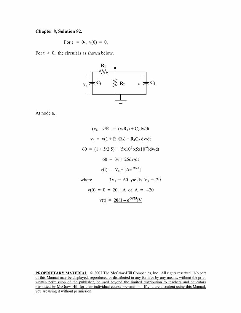
PROPRIETARY MATERIAL. © 2007 The McGraw-Hill Companies, Inc. All rights reserved. No part
of this Manual may be displayed, reproduced or distributed in any form or by any means, without the prior
written permission of the publisher, or used beyond the limited distribution to teachers and educators
permitted by McGraw-Hill for their individual course preparation. If you are a student using this Manual,
you are using it without permission.
Chapter 8, Solution 82.
For t = 0-, v(0) = 0.
For t > 0, the circuit is as shown below.
At node a,
(vo – v/R1 = (v/R2) + C2dv/dt
vo = v(1 + R1/R2) + R1C2 dv/dt
60 = (1 + 5/2.5) + (5x106 x5x10
-6)dv/dt
60 = 3v + 25dv/dt
v(t) = Vs + [Ae-3t/25
]
where 3Vs = 60 yields Vs = 20
v(0) = 0 = 20 + A or A = –20
v(t) = 20(1 – e-3t/25
)V
R1
R2
a
+
v C2C1
+
vo
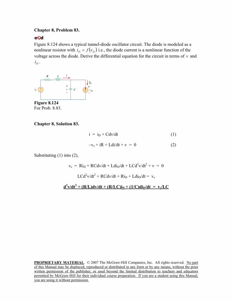
PROPRIETARY MATERIAL. © 2007 The McGraw-Hill Companies, Inc. All rights reserved. No part
of this Manual may be displayed, reproduced or distributed in any form or by any means, without the prior
written permission of the publisher, or used beyond the limited distribution to teachers and educators
permitted by McGraw-Hill for their individual course preparation. If you are a student using this Manual,
you are using it without permission.
Chapter 8, Problem 83.
Figure 8.124 shows a typical tunnel-diode oscillator circuit. The diode is modeled as a
nonlinear resistor with DDvfi i.e., the diode current is a nonlinear function of the
voltage across the diode. Derive the differential equation for the circuit in terms of v and
Di .
Figure 8.124
For Prob. 8.83.
Chapter 8, Solution 83.
i = iD + Cdv/dt (1)
–vs + iR + Ldi/dt + v = 0 (2)
Substituting (1) into (2),
vs = RiD + RCdv/dt + LdiD/dt + LCd2v/dt
2 + v = 0
LCd2v/dt
2 + RCdv/dt + RiD + LdiD/dt = vs
d2v/dt
2 + (R/L)dv/dt + (R/LC)iD + (1/C)diD/dt = vs/LC