chapter 5. mouse and tackball - ian · pdf filechapter 5. mouse and tackball 5.1 history ......
TRANSCRIPT

Computer Peripherals
School of Computer Engineering
Nanyang Technological University
Singapore
These notes are part of a 3rd year undergraduate course called "Computer Peripherals", taught at Nanyang Technological University
School of Computer Engineering in Singapore, and developed by Associate Professor Kwoh Chee Keong. The course covered
various topics relevant to modern computers (at that time), such as displays, buses, printers, keyboards, storage devices etc... The
course is no longer running, but these notes have been provided courtesy of him although the material has been compiled from
various sources and various people. I do not claim any copyright or ownership of this work; third parties downloading the material
agree to not assert any copyright on the material. If you use this for any commercial purpose, I hope you would remember where you
found it.
Further reading is suggested at the end of each chapter, however you are recommended to consider a much more modern alternative
reference text as follows:
Computer Architecture: an embedded approach Ian McLoughlin
McGraw-Hill 2011
Chapter 5. Mouse and Tackball
5.1 History
The mouse was invented in 1965 at Stanford Research Institute by Douglas. Theoriginal mouse used a pair of wheels turning potentiometer shafts to encode X and Ymotion into analog signals.
The mouse was redesigned at the Xerox Palo Alto Research Centre to use ballbearings as wheels, and optical shaft encoders to generate digital quadrature signals.The mouse was again redesigned to use a single large ball driving mechanical digitalshaft encoders, thus eliminating the drag of side-slipping wheels.
Early mechanical mice were unreliable: the balls or wheels would get dirty andslip rather than roll or the commutators would get dirty and skip. All of themechanical parts made the mice very expensive. The problems with mechanical miceled to the development of optical mice, which track motion without moving parts byoptically imaging a special surface onto an optical detector within the mouse. MITand Xerox had independently built completely different optical designs within days ofeach other some fifteen years after the original invention of the mouse.
An-acoustic mouse was invented after the optical mouse, but it was not a marketsuccess.
Mice are supplied on computers and workstations from Apollo, Apple, DEC,IBM, SUN Microsystems, Symbolics, Xerox, and many others. The largest mousevendors are Alps Electric, Logitech, and Mouse Systems. The mouse has now becomethe universal Graphic User Interface (GUI) input device.
Mice are commonly rated by their resolution, typically stated as counts per inch(cpi) of travel. Most mice have a resolution of 100 to 200 cpi. The higher theresolution, the less motion is required to move the cursor a given distance, but theharder it is to position the mouse on an exact point. The resolution can be decreasedby the software to make accurate positioning easier by dividing the count from themouse.
Mice generally include one to four push buttons on the upper surface of thehousing. A button is pushed to select the object pointed to, such as an item in a menu,or to mark a position, such as the start of a text block to be moved. Push buttons canalso be used for other application-dependent functions.
www.lintech.org
Mouse 2
5.2 Motion Sensing
Types of Motion. Mice sense their displacement and direction of motion across awork surface. This motion can be sensed in one of two ways: relative to the worksurface or relative to the mouse.
Motion Relative to the Work Surface. When a mouse senses motion relative to awork surface, its output corresponds to its motion relative to the X and Y axes of thesurface. The surface is usually printed with a regular pattern of lines or dots; sensingmeans within the mouse detect its motion over the patterned surface. The output isindependent of the orientation or rotation of the mouse, within limits, and is relatedonly to its motion over the work surface.
Motion Relative to the Mouse. When the mouse senses motion relative to itself, itdoes so independently of its orientation on the work surface. It can be moved in anydirection, or rotated, and its output will correspond only to the motion relative to itsown X and Y axes. Its orientation with respect to the work surface is unimportant
5.3 Mechanical Mice
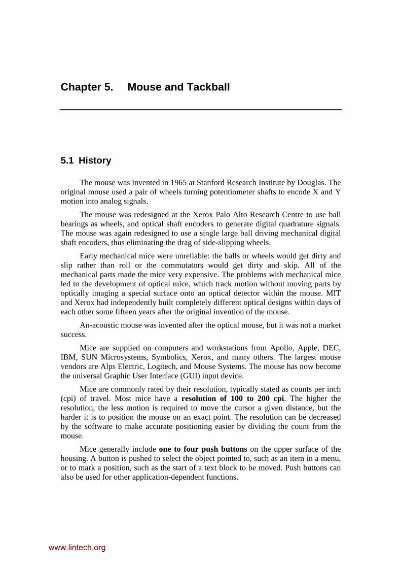
Motion Tracking Methods. Mechanical mice use wheels or balls to convert theirlinear motion across a surface into the rotary motion of commutators or shaftencoders.
Figure 0-1 A Typical mechanical mouse with ball and shafts
www.lintech.org
Mouse 3
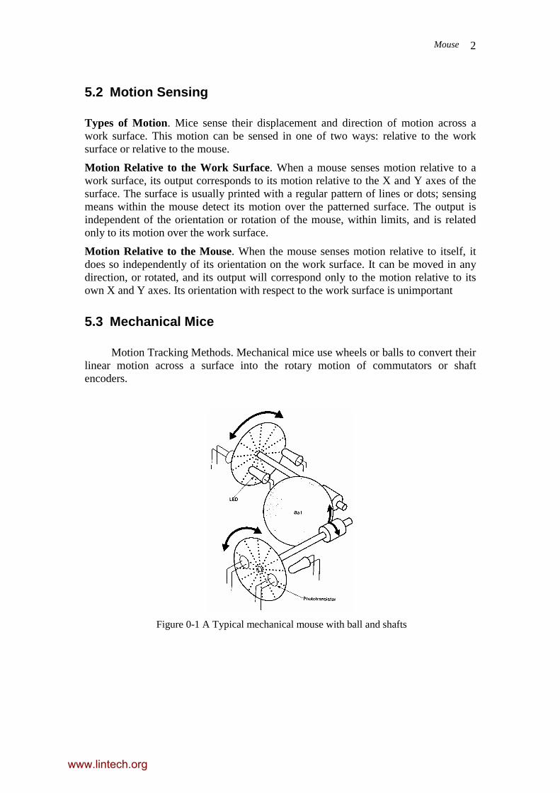
Figure 0-2 Ball and Shaft
Mice that use a ball for motion sensing can be represented by the system shownFigure 0-1 and Figure 0-2. The velocity of the circumference of the ball, Vr, is equalto the velocity of the mouse, V. Since the shaft is not directly attached to the axis ofthe ball but is resting against its circumference. Assuming no slippage, the velocity ofthe circumference of the shaft is equal to the velocity of the circumference of the ball.
The shaft's angular velocity and rotation are now related to the motion of themouse with the equations above, but the radius, R, is now much smaller and the shaftrotates much faster.
ω = V/R1 radians per second
where V= the velocity of the mouse and R1 = the radius of the shaft. As the shaft ismade smaller, it rotates faster for a given mouse velocity.
How the Motion is Transmitted to the Sensors. The shafts that are rotateddirectly or indirectly by a wheel or ball are connected directly to motion sensors.These sensors can take a variety of forms and can be classified as one of two types:resistive sensing elements or optical interrupters.
5.3.1 Optical Interrupters.
Optomechanical mice use a device called an optointerrupter to generate the Aand B quadrature signals. As shown in Figure 0-3 Optical encoder with quadratureoutputs, the optomechanical system consists of a light source, usually a light emittingdiode (LED), a photodetector, and the optointerrupter, which is connected to therotating shaft of the mouse. The interrupter has a series of alternating black and whitestrips that allow light from the LED to shine onto the detector. As the interrupterrotates past the light beam, the solid segments between the slots will interrupt thebeam and a series of voltage pulses will appear at the output of the detector.
A second quadrature output is obtained by using a second LED and detector thatare offset from the first LED and detector by one-quarter of the angle of the radialslots or by using slots that are offset by one-quarter of their period, similar to acommutator's offset conductive segments. A mask with two holes through it may beused with the commutator to ensure that the light beams are in quadrature with respectto the rotation of the interrupter. The mask can be pierced or molded so that the holesare precisely 90 degrees out of phase.
www.lintech.org

Mouse 4
Figure 0-3 Optical encoder with quadrature outputs
Figure 0-4 Quadrature signals
The output from the optical encoder is two quadrature signals, as shown inFigure 0-4 Quadrature signals. The direction can be sensed by examining the phaserelationship of the two signals. If signal A is high when a rising edge occurs on signalB, then the motion is in the forward direction. The signals can be connected directly toan input port and all decoding and counting performed in software if themicroprocessor is fast enough.
5.4 Trackballs
The trackball is used for similar purposes as the mouse. Its internal design isalmost identical to a mouse and can be regarded as a mouse on its back and left in astationary position. The trackball pre-dates the mouse and it is popularly believed thatthe mouse was conceived by turning a trackball upside down and moving it across atable surface. The main features of a trackball are shown in Figure 0-5 A trackball. Ametal or plastic ball is mounted in a frame, with only a small portion protrudingthrough the opening in the top of the frame. The ball is supported by twoperpendicular rods so that when the ball is rotated left or right, one rod rotates, andwhen it is rotated forward or backward, the other rod rotates.
Figure 0-5 A trackball
The ball is completely free to rotate within its socket. It is operated by the palmof the hand and the movements sensed by the ball being in contact with two rollers
www.lintech.org
Mouse 5
inside the casing in the same manner as a mechanical mouse. The rollers' movementsagain are detected by sensing the rotations of discs attached to their ends. This sensingcan be achieved by electrical contacts or by LEDs and photodetectors. Like themouse, a trackball unit will usually include some buttons which can be reached by thetips of the fingers while the palm of the hand is resting on the ball.
For most purposes the mouse is more popular than the trackball but in situationswhere space is tight or no suitable surface is available the trackball is used. Currentlyit is commonly integrated into the casing of most laptop personal computers.
Advantages:
1. No Work space needed.
2. No missing mouse.
3. Often used to position cursor in lap-top and notebook computers, and ATCRadar displays, etc.
5.5 Optical Mice
Dirt on the work surface and on the ball bearings or wheels and slack and playin the mechanical linkages will cause slippage, resulting in loss of accuracy anderratic movement. The optical mouse eliminates these problems.
Work Surface. Optical mice generally use a special work surface in conjunctionwith an optical system and photodetectors to generate motion signals. The specialwork surface, or mice pad, is usually printed with a grid of lines, dots, or othergeometric shapes that can be illuminated and focused onto a detector that generatessignals proportional to the movement of the mouse.
There are many types of Optical Systems. The most common form is theOrthogonal Printed Lines.
5.5.1 Optical mouse with two-coloured line pad
In an orthogonal printed line pad, the optical mouse pad has a reflective surfaceand is printed with a grid of closely spaced orthogonal lines as shown in Figure 0-6Optical mouse pad showing ink lines. The vertical lines are printed in one colour, thehorizontal lines in another. The colours are chosen to absorb light at differentfrequencies, so that the mouse's optical detectors can differentiate between horizontaland vertical movement.
www.lintech.org

Mouse 6
Figure 0-6 Optical mouse pad showing ink lines
The absorption spectra of the two inks should have a narrow peak of maximumabsorption at its own wavelength and a very low level of absorption at the other ink'swavelength. The two wavelengths commonly used coincide with those of standard redand infrared light emitting diodes: 670 and 940 nanometers, as shown in Figure 0-7Red and IR Spectral response of ink.
Figure 0-7 Red and IR Spectral response of ink
When the surface of the pad is illuminated as shown in Figure 0-8, light fromthe LED is reflected unattenuated directly from the mirror surface of the mouse pad,and is reflected, but attenuated, from the light absorbent ink lines. This light and darkobject can be focused with a lens and mirror system to form an image on a fourelement photodetector. As the mouse is moved across the pad, the light and darkimage will move across the elements of the detector, and each will generate a currentthat is proportional to the amount of light striking it.
www.lintech.org
Mouse 7
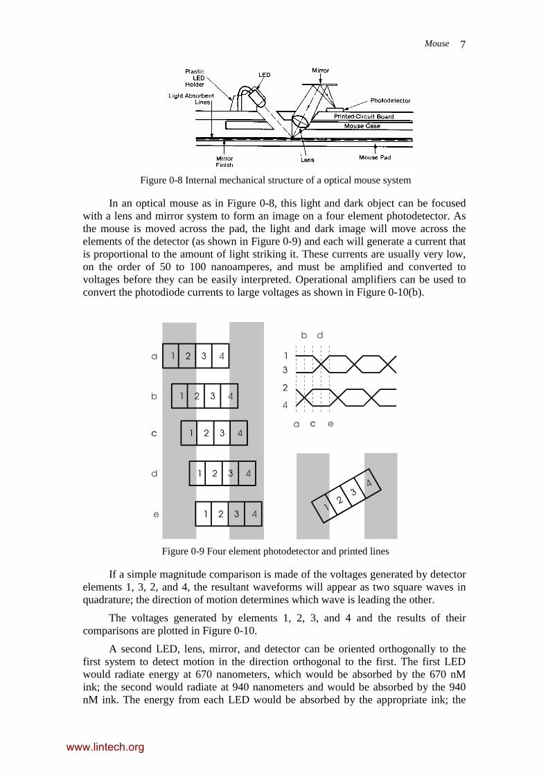
Figure 0-8 Internal mechanical structure of a optical mouse system
In an optical mouse as in Figure 0-8, this light and dark object can be focusedwith a lens and mirror system to form an image on a four element photodetector. Asthe mouse is moved across the pad, the light and dark image will move across theelements of the detector (as shown in Figure 0-9) and each will generate a current thatis proportional to the amount of light striking it. These currents are usually very low,on the order of 50 to 100 nanoamperes, and must be amplified and converted tovoltages before they can be easily interpreted. Operational amplifiers can be used toconvert the photodiode currents to large voltages as shown in Figure 0-10(b).
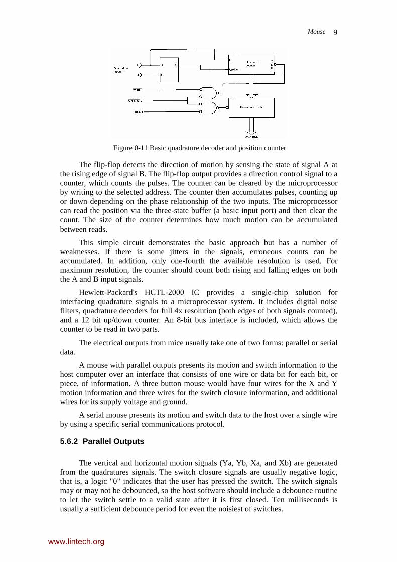
Figure 0-9 Four element photodetector and printed lines
If a simple magnitude comparison is made of the voltages generated by detectorelements 1, 3, 2, and 4, the resultant waveforms will appear as two square waves inquadrature; the direction of motion determines which wave is leading the other.
The voltages generated by elements 1, 2, 3, and 4 and the results of theircomparisons are plotted in Figure 0-10.
A second LED, lens, mirror, and detector can be oriented orthogonally to thefirst system to detect motion in the direction orthogonal to the first. The first LEDwould radiate energy at 670 nanometers, which would be absorbed by the 670 nMink; the second would radiate at 940 nanometers and would be absorbed by the 940nM ink. The energy from each LED would be absorbed by the appropriate ink; the
www.lintech.org

Mouse 8
other ink would be transparent to light of the wrong wavelength and there would beno absorption.
Figure 0-10 Quadrature signal generation in an optical mouse system
5.5.2 Optical mouse with one-coloured line pad
The above section discussed the optical mouse with two-coloured line pad. However,a variation of the design has produce optical mouse that can work with one-colouredlined pad. How? I will leave this to the discussion in your tutorial.
5.6 Electrical Outputs from Mouse
5.6.1 Types of Data
Quadrature signals are usually generated for a mouse, however, unless arelatively fast microprocessor is used which does not need to perform many othertasks while reading the encoder signals, rapid motion may be missed. A hardwareimplementation of the quadrature decoder, as shown in Figure 0-11 is usually requiredfor the serial interface, removes the speed-critical tasks from the microprocessor.
www.lintech.org
Mouse 9
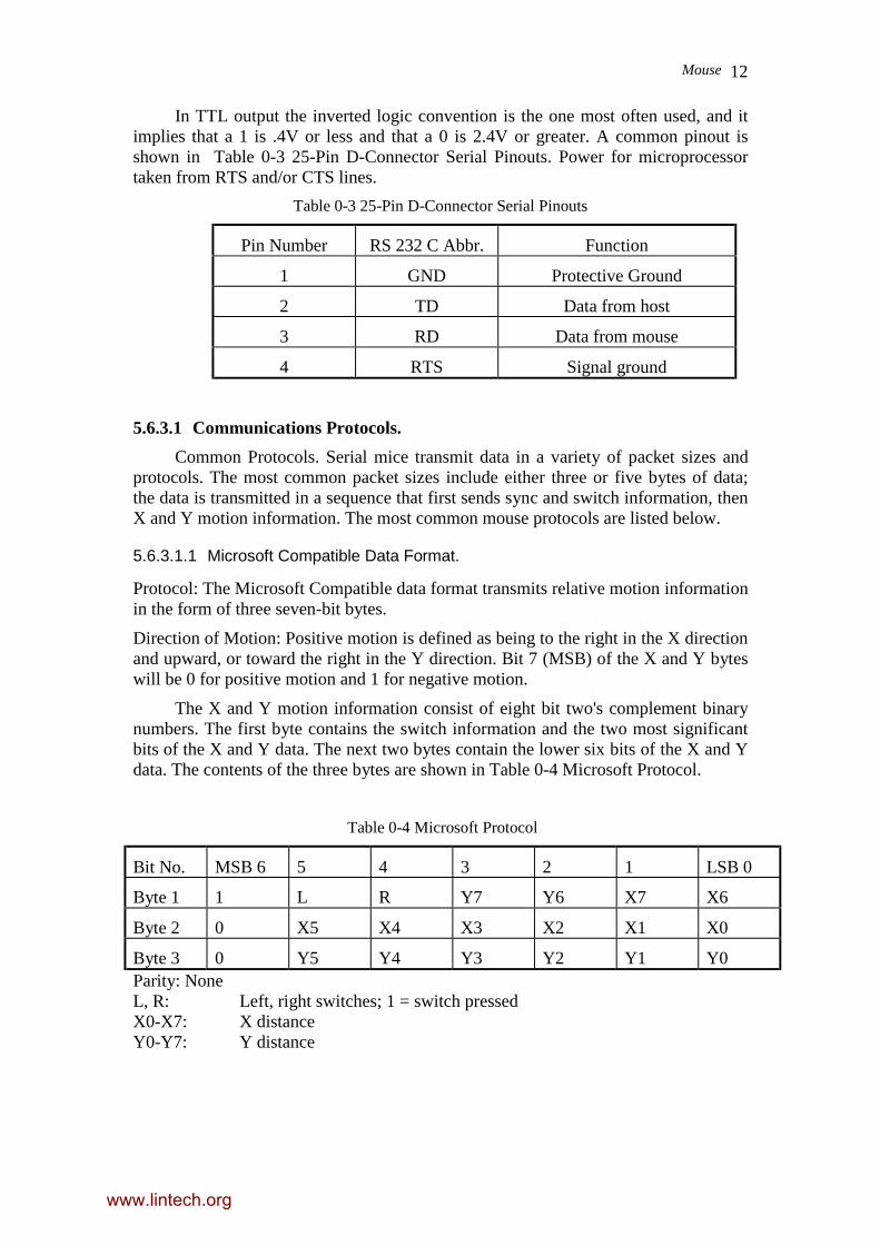
Figure 0-11 Basic quadrature decoder and position counter
The flip-flop detects the direction of motion by sensing the state of signal A atthe rising edge of signal B. The flip-flop output provides a direction control signal to acounter, which counts the pulses. The counter can be cleared by the microprocessorby writing to the selected address. The counter then accumulates pulses, counting upor down depending on the phase relationship of the two inputs. The microprocessorcan read the position via the three-state buffer (a basic input port) and then clear thecount. The size of the counter determines how much motion can be accumulatedbetween reads.
This simple circuit demonstrates the basic approach but has a number ofweaknesses. If there is some jitters in the signals, erroneous counts can beaccumulated. In addition, only one-fourth the available resolution is used. Formaximum resolution, the counter should count both rising and falling edges on boththe A and B input signals.
Hewlett-Packard's HCTL-2000 IC provides a single-chip solution forinterfacing quadrature signals to a microprocessor system. It includes digital noisefilters, quadrature decoders for full 4x resolution (both edges of both signals counted),and a 12 bit up/down counter. An 8-bit bus interface is included, which allows thecounter to be read in two parts.
The electrical outputs from mice usually take one of two forms: parallel or serialdata.
A mouse with parallel outputs presents its motion and switch information to thehost computer over an interface that consists of one wire or data bit for each bit, orpiece, of information. A three button mouse would have four wires for the X and Ymotion information and three wires for the switch closure information, and additionalwires for its supply voltage and ground.
A serial mouse presents its motion and switch data to the host over a single wireby using a specific serial communications protocol.
5.6.2 Parallel Outputs
The vertical and horizontal motion signals (Ya, Yb, Xa, and Xb) are generatedfrom the quadratures signals. The switch closure signals are usually negative logic,that is, a logic "0" indicates that the user has pressed the switch. The switch signalsmay or may not be debounced, so the host software should include a debounce routineto let the switch settle to a valid state after it is first closed. Ten milliseconds isusually a sufficient debounce period for even the noisiest of switches.
www.lintech.org

Mouse 10
5.6.2.1 Standard Pinouts/Connectors.
Standard Connector. The most common form of connector for parallel mice hasbeen a 9-pin D-subminiature male plug. There is a limited number of connectorpinouts and they are tabulated in Table 0-1 Quad Pinouts.
www.lintech.org

Mouse 11
Table 0-1 Quad Pinouts
Pin Number MouseSystems
Logitech Apple
1 +5V +5V Ground
2 Xa Ya +5V
3 Xb Yb Ground
4 Ya Xb Xa
5 Yb Xa Xb
6 L switch Ground Ground
7 M switch M switch Switch
8 R switch R switch Yb
9 Ground L switch Ya
5.6.2.2 Microsoft Connector.
MicroSoft uses a 9-pin mini-DIN connector; details are shown in Table 0-2MicroSoft Mini-DIN Pinouts.
Table 0-2 MicroSoft Mini-DIN Pinouts
Pin Number Function
1 +5V
2 Xa
3 Xb
4 Ya
5 Yb
6 switch 1
7 switch 2
8 switch 3
9 Ground
5.6.3 Serial Output
Electrical Characteristics. Serial mice will usually have an internal microcontrolleror state machine that can interpret the motion and switch information and convert it toa simple serial output.
Serial mice generate outputs that are in one of two forms: RS-232 or TTLvoltage levels.
www.lintech.org
Mouse 12
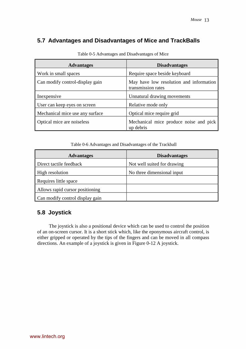
In TTL output the inverted logic convention is the one most often used, and itimplies that a 1 is .4V or less and that a 0 is 2.4V or greater. A common pinout isshown in Table 0-3 25-Pin D-Connector Serial Pinouts. Power for microprocessortaken from RTS and/or CTS lines.
Table 0-3 25-Pin D-Connector Serial Pinouts
Pin Number RS 232 C Abbr. Function
1 GND Protective Ground
2 TD Data from host
3 RD Data from mouse
4 RTS Signal ground
5.6.3.1 Communications Protocols.
Common Protocols. Serial mice transmit data in a variety of packet sizes andprotocols. The most common packet sizes include either three or five bytes of data;the data is transmitted in a sequence that first sends sync and switch information, thenX and Y motion information. The most common mouse protocols are listed below.
5.6.3.1.1 Microsoft Compatible Data Format.
Protocol: The Microsoft Compatible data format transmits relative motion informationin the form of three seven-bit bytes.
Direction of Motion: Positive motion is defined as being to the right in the X directionand upward, or toward the right in the Y direction. Bit 7 (MSB) of the X and Y byteswill be 0 for positive motion and 1 for negative motion.
The X and Y motion information consist of eight bit two's complement binarynumbers. The first byte contains the switch information and the two most significantbits of the X and Y data. The next two bytes contain the lower six bits of the X and Ydata. The contents of the three bytes are shown in Table 0-4 Microsoft Protocol.
Table 0-4 Microsoft Protocol
Bit No. MSB 6 5 4 3 2 1 LSB 0
Byte 1 1 L R Y7 Y6 X7 X6
Byte 2 0 X5 X4 X3 X2 X1 X0
Byte 3 0 Y5 Y4 Y3 Y2 Y1 Y0Parity: NoneL, R: Left, right switches; 1 = switch pressedX0-X7: X distanceY0-Y7: Y distance
www.lintech.org
Mouse 13
5.7 Advantages and Disadvantages of Mice and TrackBalls
Table 0-5 Advantages and Disadvantages of Mice
Advantages Disadvantages
Work in small spaces Require space beside keyboard
Can modify control-display gain May have low resolution and informationtransmission rates
Inexpensive Unnatural drawing movements
User can keep eyes on screen Relative mode only
Mechanical mice use any surface Optical mice require grid
Optical mice are noiseless Mechanical mice produce noise and pickup debris
Table 0-6 Advantages and Disadvantages of the Trackball
Advantages Disadvantages
Direct tactile feedback Not well suited for drawing
High resolution No three dimensional input
Requires little space
Allows rapid cursor positioning
Can modify control display gain
5.8 Joystick
The joystick is also a positional device which can be used to control the positionof an on-screen cursor. It is a short stick which, like the eponymous aircraft control, iseither gripped or operated by the tips of the fingers and can be moved in all compassdirections. An example of a joystick is given in Figure 0-12 A joystick.
www.lintech.org
Mouse 14
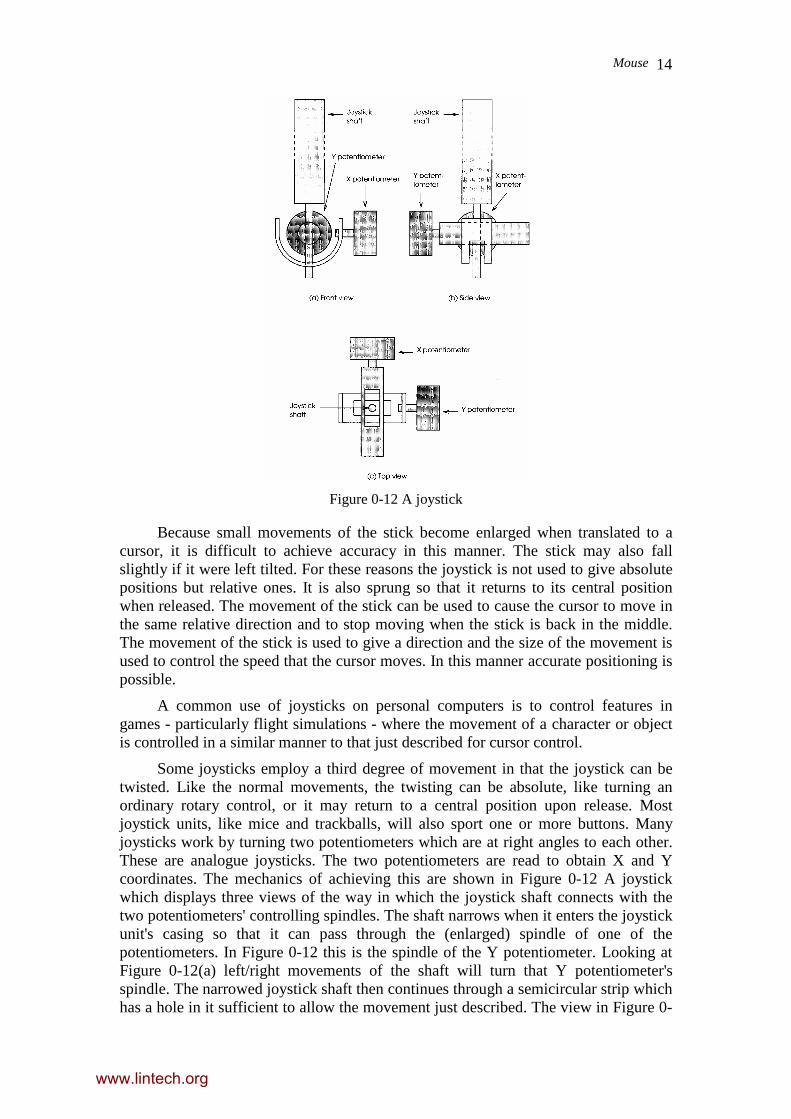
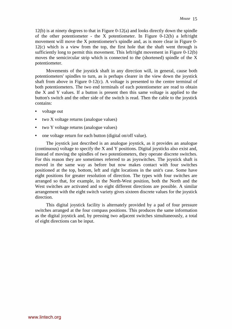
Figure 0-12 A joystick
Because small movements of the stick become enlarged when translated to acursor, it is difficult to achieve accuracy in this manner. The stick may also fallslightly if it were left tilted. For these reasons the joystick is not used to give absolutepositions but relative ones. It is also sprung so that it returns to its central positionwhen released. The movement of the stick can be used to cause the cursor to move inthe same relative direction and to stop moving when the stick is back in the middle.The movement of the stick is used to give a direction and the size of the movement isused to control the speed that the cursor moves. In this manner accurate positioning ispossible.
A common use of joysticks on personal computers is to control features ingames - particularly flight simulations - where the movement of a character or objectis controlled in a similar manner to that just described for cursor control.
Some joysticks employ a third degree of movement in that the joystick can betwisted. Like the normal movements, the twisting can be absolute, like turning anordinary rotary control, or it may return to a central position upon release. Mostjoystick units, like mice and trackballs, will also sport one or more buttons. Manyjoysticks work by turning two potentiometers which are at right angles to each other.These are analogue joysticks. The two potentiometers are read to obtain X and Ycoordinates. The mechanics of achieving this are shown in Figure 0-12 A joystickwhich displays three views of the way in which the joystick shaft connects with thetwo potentiometers' controlling spindles. The shaft narrows when it enters the joystickunit's casing so that it can pass through the (enlarged) spindle of one of thepotentiometers. In Figure 0-12 this is the spindle of the Y potentiometer. Looking atFigure 0-12(a) left/right movements of the shaft will turn that Y potentiometer'sspindle. The narrowed joystick shaft then continues through a semicircular strip whichhas a hole in it sufficient to allow the movement just described. The view in Figure 0-
www.lintech.org
Mouse 15
12(b) is at ninety degrees to that in Figure 0-12(a) and looks directly down the spindleof the other potentiometer - the X potentiometer. In Figure 0-12(b) a left/rightmovement will move the X potentiometer's spindle and, as is more clear in Figure 0-12(c) which is a view from the top, the first hole that the shaft went through issufficiently long to permit this movement. This left/right movement in Figure 0-12(b)moves the semicircular strip which is connected to the (shortened) spindle of the Xpotentiometer.
Movements of the joystick shaft in any direction will, in general, cause bothpotentiometers' spindles to turn, as is perhaps clearer in the view down the joystickshaft from above in Figure 0-12(c). A voltage is presented to the centre terminal ofboth potentiometers. The two end terminals of each potentiometer are read to obtainthe X and Y values. If a button is present then this same voltage is applied to thebutton's switch and the other side of the switch is read. Then the cable to the joystickcontains:
• voltage out
• two X voltage returns (analogue values)
• two Y voltage returns (analogue values)
• one voltage return for each button (digital on/off value).
The joystick just described is an analogue joystick, as it provides an analogue(continuous) voltage to specify the X and Y positions. Digital joysticks also exist and,instead of moving the spindles of two potentiometers, they operate discrete switches.For this reason they are sometimes referred to as joyswitches. The joystick shaft ismoved in the same way as before but now makes contact with four switchespositioned at the top, bottom, left and right locations in the unit's case. Some haveeight positions for greater resolution of direction. The types with four switches arearranged so that, for example, in the North-West position, both the North and theWest switches are activated and so eight different directions are possible. A similararrangement with the eight switch variety gives sixteen discrete values for the joystickdirection.
This digital joystick facility is alternately provided by a pad of four pressureswitches arranged at the four compass positions. This produces the same informationas the digital joystick and, by pressing two adjacent switches simultaneously, a totalof eight directions can be input.
www.lintech.org