chapter 10 – foundations and equipment pads construction of traffic control signal foundations and...
TRANSCRIPT

SIGNALS AND LIGHTING FIELD GUIDE
Foundations and Equipment Pads
10-1
CHAPTER 10 – FOUNDATIONS AND EQUIPMENT PADS
10.1 Standard Plates, Standard Plans and Detail Drawings
Standard plates, standard plans and detail sheets included in the plan contain essential details about the construction and installation of foundations and equipment pads. Standard plates for a project will be listed in the plan. Standard plates that apply to a standalone traffic control signal project are listed on the title sheet of the plan. Standard plates that apply to a standalone lighting project are listed on the quantities sheet of the plan.
Refer to the specific standard plate or standard plan that applies to the foundation or equipment pad required to be constructed. Current standard plates and plans are available online or upon request from the project engineer.
Standard plates and plans can be revised and updated as design practices and technology changes. Reference the standard plates listed in the plan to ensure the most current standard plates are being used before work begins on any structure.
Standard plans and detail sheets for both traffic control signal and lighting projects are found in the plan.
It is important for the contractor to carry all the contract documents with them at all times during the course of the project since there will be instances where one contract document will reference another contract document. For example, the NOTES section of standard plates, standard plans and detail sheets may reference a specific area of the MnDOT Standard Specifications for Construction (Spec Book) as presented in Figure 10-1.
Another example is the specification reference box found on the lower right corner of standard plates. The box indicates which specification number(s) in the Spec Book contractors should pay close attention to for technical standards of materials and construction.
Figure 10-1: Example of Standard Plate

SIGNALS AND LIGHTING FIELD GUIDE
Foundations and Equipment Pads
10-2
Some information found on standard plates, standard plans and detail sheets includes:
• Type of concrete mix required. • The diameter of the anchor bolt circle. • Minimum conduit size and type. • Number of conduits required in the foundation. • Reinforcement bar size and placement. • Minimum projection of the conduit above the foundation top. • Overall dimensions of the foundation.
Most standard plates, standard plans and detail sheets contain an area dedicated to “NOTES”. It is essential that these notes be carefully read and understood.
10.2 Standard Specification Requirements
10.5.1. GENERAL REQUIREMENTS FOR TRAFFIC CONTROL SIGNAL AND LIGHTING FOUNDATIONS
General requirements used for traffic control signal and lighting concrete foundations and equipment pads are found in Specification 2401 “Concrete Bridge Construction.” Specification 2401 covers a wide spectrum of items, some of which do not apply to traffic control signal and lighting foundations and equipment pads.
Some items that do apply in Specification 2401 are:
• Materials- concrete and reinforcement bars. • Construction requirements-forms, placement
of concrete, compaction of concrete, surface finish, and concrete curing and protection.
Here are a few general requirements for traffic control signal and lighting foundations and equipment pads found in Specification 2401:
• Complete the placement of forms, falsework, bracing, and reinforcement bars for the entire concrete cast and have concrete placement and finishing equipment and curing material on site before placing the concrete.
• Preform mixing, placing, and finishing of concrete under adequate lighting conditions (2401.3C Placement of Concrete).
• Compact concrete using mechanical vibration applied internally. Operate vibrators at a frequency of at least 4,500 impulses per min [75 Hz].
Figure 10-2: Placement of Forms, Falsework, Bracing, and Reinforcement Bars (2401.3C.1)
Figure 10-3: Compaction of Concrete (2401.3D)

SIGNALS AND LIGHTING FIELD GUIDE
Foundations and Equipment Pads
10-3
• Provide ordinary surface finish on formed surfaces of concrete structures. • Maintain a moist surface condition during the curing period (2401.3G Concrete Curing
Protection) as shown in Figure 10-6.
Allow at least seven days of curing period to elapse based on 100% design strength for traffic control signal and light foundations and equipment pads before installing poles and service cabinets. Refer to Table 2401-2 in the Spec Book if the concrete surface temperature falls below 70°F to compute the number of curing days required for adequate strength. If the two methods produce different results the engineer will determine if the concrete has cured adequately.
Other standard specification requirements in addition to Specification 2401 used in the construction and installation of traffic control signal and lighting foundations and equipment pads:
• 2411 Minor Concrete Structures • 2451 Structure Excavations and Backfills • 2545.3F Concrete Light Foundation and Equipment Pad Installation • 2565.3 F Concrete Foundations • 3756 Plastic Curing Blankets • 3813 Lighting System Anchorages, and 3385 Anchor Rods
Figure 10-4: PA Traffic Control Signal Pole Foundation (2401.3F.2.a Ordinary Surface Finish)
Figure 10-5: Light Foundation - Design E (2401.3F.2.a Ordinary Surface Finish)
Figure 10-6: Plastic Curing Blankets for Use as a Curing Cover to Maintain a Moist Surface (3765)

SIGNALS AND LIGHTING FIELD GUIDE
Foundations and Equipment Pads
10-4
Brace foundation and equipment pad conduits, anchor rods, ground rod electrodes, and other equipment in position and at the necessary height with a rigid metal template. Keep the template in place for at least 24 hours after concrete placement.
The Engineer will reject foundations if anchor rods, conduits, and ground rod electrodes are improperly aligned after the concrete cures. Do not enlarge bolt holes in transformer base plates to allow shifted anchors or alter the transformer base plate openings to accommodate misaligned conduits and ground rod electrodes.
Figure 10-7: Standard Specification 2565.3F.2
Proper installation of anchor rods, conduits, and ground rod electrodes in foundations is the responsibility of the contractor. Use rigid metal templates that match the bolt pattern and opening of the base plate. Secure the template to the anchor rods to avoid movement during placing and curing of the concrete and ensure proper alignment.
Before placing concrete, tape anchor rod threads that will be exposed above the foundation to prevent contamination by concrete.
Provide foundation and equipment pad anchor rods in accordance with Specifications 3813 Lighting System Foundations and 3385 Anchor Rods. Standard plates and detail sheets may specify type of anchor rod material.
Specification 3385 requires galvanized Type A, Type B, and Type C anchor rods to have the ASTM F1554 specification supplementary requirement S3 for permanent grade identification.
ASTM F1554 S3 states that instead of color coding as specified within ASTM 19.1, the end of the anchor rod intended to project from the concrete shall be steel die stamped with the grade identification as represented in Figure 10- and as follows: Grade 36=AB36, Grade 55=AB55, Grade 105=AB105.
In addition to the required permanent grade identification on the end of the anchor rod, color coding may be allowed to help facilitate easy identification in the field but it is not required.
Specification requirements may become outdated in the Spec Book. Therefore, it is essential that the contractor and the inspector check other contract documents, such as the special provisions for the project, for any updated or revised requirement language to the construction and installation of foundations and equipment pads before work begins on any structure.
Figure 10-8: The End of Anchor Rod Steel Die Stamped with the Grade
Figure 10-9: Color Coding
SIGNALS AND LIGHTING FIELD GUIDE
Foundations and Equipment Pads
10-5
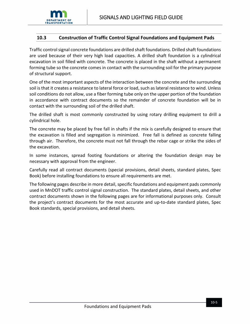
10.3 Construction of Traffic Control Signal Foundations and Equipment Pads
Traffic control signal concrete foundations are drilled shaft foundations. Drilled shaft foundations are used because of their very high load capacities. A drilled shaft foundation is a cylindrical excavation in soil filled with concrete. The concrete is placed in the shaft without a permanent forming tube so the concrete comes in contact with the surrounding soil for the primary purpose of structural support.
One of the most important aspects of the interaction between the concrete and the surrounding soil is that it creates a resistance to lateral force or load, such as lateral resistance to wind. Unless soil conditions do not allow, use a fiber forming tube only on the upper portion of the foundation in accordance with contract documents so the remainder of concrete foundation will be in contact with the surrounding soil of the drilled shaft.
The drilled shaft is most commonly constructed by using rotary drilling equipment to drill a cylindrical hole.
The concrete may be placed by free fall in shafts if the mix is carefully designed to ensure that the excavation is filled and segregation is minimized. Free fall is defined as concrete falling through air. Therefore, the concrete must not fall through the rebar cage or strike the sides of the excavation.
In some instances, spread footing foundations or altering the foundation design may be necessary with approval from the engineer.
Carefully read all contract documents (special provisions, detail sheets, standard plates, Spec Book) before installing foundations to ensure all requirements are met.
The following pages describe in more detail, specific foundations and equipment pads commonly used in MnDOT traffic control signal construction. The standard plates, detail sheets, and other contract documents shown in the following pages are for informational purposes only. Consult the project’s contract documents for the most accurate and up-to-date standard plates, Spec Book standards, special provisions, and detail sheets.
SIGNALS AND LIGHTING FIELD GUIDE
Foundations and Equipment Pads
10-6
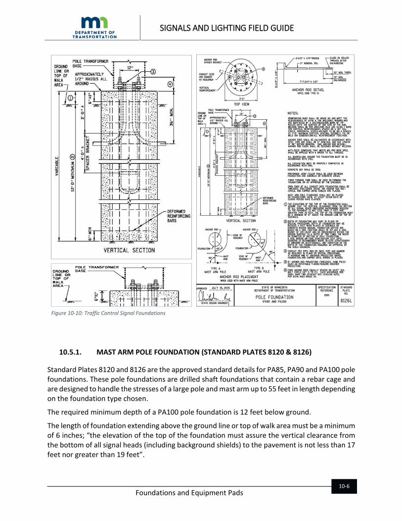
10.5.1. MAST ARM POLE FOUNDATION (STANDARD PLATES 8120 & 8126)
Standard Plates 8120 and 8126 are the approved standard details for PA85, PA90 and PA100 pole foundations. These pole foundations are drilled shaft foundations that contain a rebar cage and are designed to handle the stresses of a large pole and mast arm up to 55 feet in length depending on the foundation type chosen.
The required minimum depth of a PA100 pole foundation is 12 feet below ground.
The length of foundation extending above the ground line or top of walk area must be a minimum of 6 inches; “the elevation of the top of the foundation must assure the vertical clearance from the bottom of all signal heads (including background shields) to the pavement is not less than 17 feet nor greater than 19 feet”.
Figure 10-10: Traffic Control Signal Foundations

SIGNALS AND LIGHTING FIELD GUIDE
Foundations and Equipment Pads
10-7
There are three ways to calculate foundation depth:
1. By identifying the type of soil. This can be done by looking at the Grading and Base Manual, Soil Classification Section (600 series section).
2. By calling the Soils Engineer. 3. By drilling the foundation to the minimum required depth in the standard plate.
The rebar cage must be placed in the center of the foundation 6 inches from the top and a minimum of 3 inches from the sides.
Figure 10-11: Mast Arm Standard Plate Notes

SIGNALS AND LIGHTING FIELD GUIDE
Foundations and Equipment Pads
10-8
MnDOT uses two types of mast arm poles: Type A (more commonly used) and Type B. The types of poles required for each project are listed in the pole notes on the intersection layout sheet of the plan. The locations of the mounting hubs for shaft-mounted signal heads differ according to the pole type. To determine the proper orientation of the anchor rods for the two types of mast arm poles, refer to the vertical section of Standard Plate 8126.
The PA pole foundations are drilled shaft foundations that require the concrete to be poured directly against soil of the drilled shaft with the primary purpose of structural support. Use a continuous fiber forming tube for only the upper portion of the foundation above grade and maximum 4 feet below grade if the sidewalls of the drilled shaft remain firm and stable.
If soil conditions do not allow the sidewalls of the drilled shaft to remain firm and stable a continuous full length forming tube with four rectangular holes cut as indicated may be used with the approval of the engineer.
The following information in Figure 10-12 and 10-15 are a copy of updated installation requirements found in the 2018 Standard Specifications for Construction Section 2565.3.
F.1.b PA 85, 90, and 100 Pole Foundations (Standard Plates 8120 and 8126) Construct PA pole foundations in accordance with 2411, “Minor Concrete Structures” and as specified in the
Contract, and in accordance with the following: Construct foundations in drilled shafts. Excavate a hole with an auger of sufficient size to the dimensions of the
foundation specified in the Contract. Minimize over excavation. Protect the sides of the drilled shaft from collapsing. Pour concrete as soon as possible after the excavation to prevent loose or soft materials from accumulating at the
bottom of the shaft that would affect the performance of the foundation. Remove loose materials at the bottom of the shaft and groundwater before placement of concrete.
Use a continuous fiber forming tube for the upper portion of the foundation above grade and maximum 4 ft below
grade. Pour concrete directly against the soil of the drilled shaft if the sidewalls remain firm and stable. A continuous full length fiber forming tube may be used to prevent the sidewalls of the shaft from collapsing with
the approval of the Engineer at no additional cost to the Department. “Full length” means more than half the depth of the drilled shaft.
When a full length fiber forming tube is needed to prevent the drilled shaft from collapsing, refer to the Frost Depth
Zone Table 2565-1 and cut four 3 in x 12 in rectangular holes into the fiber forming tube before installing into the drilled shaft. Cut two rectangular holes approximately 180 degrees apart, 6 ft to 7 ft below grade if the project site is located in Zone 1, and 4 ft to 5 ft below grade if the project site is located in Zone 2. Rotate the forming tube 90 degrees and cut two more rectangular holes 180 degree apart approximately 1 ft lower from the first two holes.
Table 2565-1Frost Depth Zone Zone Depth of Rectangular Holes Below Grade
1 6 ft- 7 ft 2 4 ft- 5 ft
* Refer to The Office of The Revisor of Statutes website for frost depth zone requirements, Minnesota Administrative Rules 1303.1600 Footing Depth for Frost Protection, https://www.revisor.mn.gov/rules/?id=1303.1600 to determine appropriate frost depth zone. During placement of the concrete, ensure concrete fills the shaft area and any void area outside the fiber forming
tube that is below grade. If soil or rock conditions not suitable for standard foundations are present, or if conditions are marginal, contact
the MnDOT Bridge Evaluation and Fabrication Methods Engineer and the MnDOT Foundations Unit for a foundation design that can be used as an alternative to the standard foundation design.
Figure 10-12: Installation Requirements for Pole Foundations from Special Provisions for Signals

SIGNALS AND LIGHTING FIELD GUIDE
Foundations and Equipment Pads
10-9
Figure 10-13: Forming Tube Slot Dimension Requirements
Figure 10-14: Foundation Guidance
During placement of the concrete, ensure concrete fills the shaft area and any void area outside the fiber forming tube that is below grade.
If soil or rock conditions not suitable for standard foundations are present, or if conditions are marginal, contact the
MnDOT Bridge Evaluation and Fabrication Methods Engineer and the MnDOT Foundations Unit for a foundation design that can be used as an alternative to the standard foundation design.
Foundation design is based on installing in a drilled shaft. Any variation to the drilled shaft requires an approval by the
District Soils Engineer. If a drilled shaft foundation is not possible obtain approval from the District Soils Engineer to conduct open excavation for the foundation before starting the work.

SIGNALS AND LIGHTING FIELD GUIDE
Foundations and Equipment Pads
10-10
10.5.2. POLE FOUNDATION TYPE BA (STANDARD PLATE 8134)
Pole foundation type BA is designed for traffic control signal poles with mast arms 60 feet to 80 feet.
The mast arm length determines drilled shaft depth, anchor bolt diameter, and bolt circle diameter of the pole foundation.
Pole foundation type BA is either a drilled shaft foundation or spread footing foundation.
Figure 10-15: Pole Foundation Install
Figure 10-16: Pole Foundation Type BA Notes
SIGNALS AND LIGHTING FIELD GUIDE
Foundations and Equipment Pads
10-11
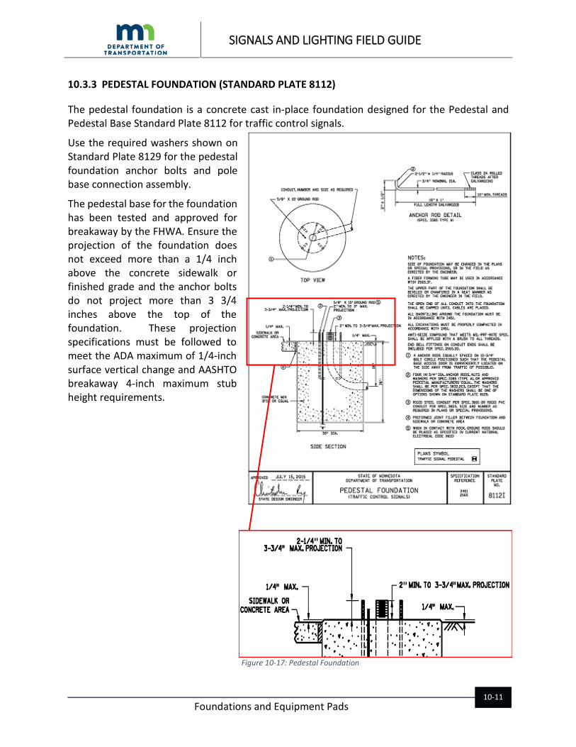
10.3.3 PEDESTAL FOUNDATION (STANDARD PLATE 8112)
The pedestal foundation is a concrete cast in-place foundation designed for the Pedestal and Pedestal Base Standard Plate 8112 for traffic control signals.
Use the required washers shown on Standard Plate 8129 for the pedestal foundation anchor bolts and pole base connection assembly.
The pedestal base for the foundation has been tested and approved for breakaway by the FHWA. Ensure the projection of the foundation does not exceed more than a 1/4 inch above the concrete sidewalk or finished grade and the anchor bolts do not project more than 3 3/4 inches above the top of the foundation. These projection specifications must be followed to meet the ADA maximum of 1/4-inch surface vertical change and AASHTO breakaway 4-inch maximum stub height requirements.
Figure 10-17: Pedestal Foundation

SIGNALS AND LIGHTING FIELD GUIDE
Foundations and Equipment Pads
10-12
There is an option to use an approved Screw-In Design Steel P foundation for pedestal poles if allowed by the district traffic office. Consult with the project’s Division SS Special Provisions for the option to use a steel screw-in foundation instead of a concrete foundation on the project.
If there is an option to use Screw-In Design Steel P foundations then there will be steel screw-in foundation specification language in Division SS Special Provisions and a Screw-In Pedestal Pole Foundation-Design Steel P detail installation sheet included in the plan for the project. The detail installation sheet can be found on MnDOT’s Traffic Engineering Signals web page in “Signal Plan Sheets” under “Detail Sheets”.
The approved Screw-In Pedestal Pole Foundation-Design Steel P can be found on MnDOT’s Approved/Qualified Products List (APL) for roadway lighting products.
10.5.3. APS PUSH BUTTON STATION FOUNDATION
The APS push button station foundation design facilitates ease of construction, mainly the flatwork, while still providing a rigid foundation for the APS push button base to breakaway properly.
The anchor rods for the foundation are 5/8 inch UNC X 7 1/2-inch stainless steel threaded rod. Drill four 3/4 inch holes 6 inches deep and insert rods using an approved epoxy found on MnDOT’s APL. Anchor rod maximum projection height above the concrete is 1 1/2 inches.
For more information on the installation of the epoxy anchor rods refer to Chapter 18 APS push buttons.
Ensure edge of sidewalk and all sidewalk joints are a minimum of 9 inches from center of the APS push button station foundation.
Figure 10-19: APS Push Button Station Detail
Figure 10-18: Screw-In Design Steel P Foundation

SIGNALS AND LIGHTING FIELD GUIDE
Foundations and Equipment Pads
10-13
The APS push button station foundation is a monolithic concrete structure, meaning the foundation is constructed in combination with the sidewalk making it all one structure.
Before placing concrete, grade a 1:2 (V:H) slope where the 6-inch sidewalk will transition to the minimum 12-inch foundation hole depth. If the foundation will not be located near the edge of the sidewalk and instead surrounded by concrete walk, then grade the 1:2 slope 360 degrees for the sidewalk to foundation transition.
Maintain a compacted aggregate bedding and thickness used for sidewalk for the foundation.
An 18 inch X 6-inch fiber forming tube may be used for the lower half of the foundation when conditions do not allow for the hole to stand open.
Figure 10-21: APS Push Button Station Foundation Details
≥ 9 in
Figure 10-20: Edge of Sidewalk a Minimum of 9 Inches from Center of Foundation

SIGNALS AND LIGHTING FIELD GUIDE
Foundations and Equipment Pads
10-14
10.5.4. 350 ATCC AND SSB CABINET EQUIPMENT PAD LAYOUT
The 350 ATCC and SSB cabinet equipment pad supports both the SSB service cabinet and the 350 ATC cabinet. The pad is also designed to support the NEMA style controller cabinet. If the NEMA style controller cabinet is required for the project, it is important to still use the 350 cabinet base template shown on the detail. This will allow for a smooth transition to install a 350 ATCC on the pad in the future without the use of a riser adapter.
See Appendix for the 350 ATCC and SSB cabinet equipment pad layout. Also included in the Appendix is the 352 ATCC and SSB cabinet equipment pad layout.
Placement of conduits because of cabinet dividers is critical. Make sure the conduits are positioned correctly in the pad by using a template. Especially for the SSB cabinet because of the assigned line and load side sections of the cabinet.
The equipment pad uses a 3G52 concrete mix with approved non-metallic fibers listed on MnDOT’s APL under Concrete “Nonmetallic Fibers”. By adding nonmetallic fibers to the concrete mix, reinforcement bars in the pad are not necessary. The fiber mixed concrete may also be used for the concrete walk and pole foundations however, the non-metallic fibers are not a substitute for the required reinforcement bars in pole foundations.
Because there is no reinforcement bar in the pad, install a grounding electrode system in accordance with Standard Plate 8106 “Grounding Electrode System for Cast-In-Place Pad”.
There is an option to wet cast the required L-shaped anchor rods in the pad or install the required straight threaded rod with the approved epoxy adhesive after the pad has been poured. Do not wet cast the straight threaded rod. Make sure the anchor rod projections are 1 ¾ inches to 2 ¼ inches to avoid installation conflict with the cabinets.
A drain is required to be installed in the pad using 1 inch PVC Schedule 40 plumbing pipe and termination vent screen. Termination vent is a fitting made with a mesh vent to fit over the end of the pipe. Make sure the vent screen and pipe are flush with the top and side of the pad.
Figure 10-22: 350 Cabinet Pad Detail

SIGNALS AND LIGHTING FIELD GUIDE
Foundations and Equipment Pads
10-15
10.4 Construction of Light Foundations and Equipment Pads
There have been recent changes in the construction and installation of MnDOT light foundations and equipment pads. Some of these changes are mentioned in this chapter. Please take time to review the material in the following pages to become familiar with important details and requirements. The following standard plates, details, and contract document language in these pages are for informational purposes only. Always consult the project’s contract documents.
Cast in-place light foundations are drilled shaft foundations. A drilled shaft foundation is cylindrical excavation in soil filled with concrete. When possible, place the concrete in the shaft without a permanent forming tube so the concrete comes in contact with the surrounding soil for the primary purpose of structural support. A forming tube may be used for the upper portion to help position the conduits and form the top of the foundation. If the surrounding soils do not allow the drilled shaft to stand open then a forming tube will be required.
Compaction around precast light foundations has been a problem in recent years for MnDOT. Precast light foundations are now required to be installed in drilled shafts (augured holes). The space between the drilled shaft and foundation will be filled with a specific backfill material in accordance with contract documents.
The drilled shaft for both cast in-place and precast is most commonly constructed by using rotary drilling equipment to drill a cylindrical hole.
Districts may allow the use of steel screw-in foundations instead of cast in-place or precast foundations. Check the project’s contract documents to see if steel screw- in foundations can be used.
MnDOT recently approved a new type of steel screw in foundation with a helix found on MnDOT’s APL. The helix type foundation is the only approved type that can be used for permanent lighting. There have been several changes in how and where steel screw-in foundations are installed. Be sure to read contract documents before acquiring and installing steel screw-in foundations.
All MnDOT service equipment pads now require two ground rod electrodes to be installed, one in the pad and the other not less than 8 feet from the pad. If the pad has a reinforcement bar, it must be bonded to the ground bus bar in the service cabinet.
Carefully read all contract documents (special provisions, detail sheets, standard plates, Spec Book) before installing foundations and equipment pads to ensure all requirements are met.
10.5.1. LIGHT FOUNDATIONS DESIGN E AND H (STANDARD PLATES 8127 AND 8128)
Light foundation Design E is designed for 40-foot light poles. Light foundation Design H is designed for 49-foot roadway light poles. Both Design E and H foundations can be cast in- place concrete, precast concrete, or steel screw-in as specified in contract documents.

SIGNALS AND LIGHTING FIELD GUIDE
Foundations and Equipment Pads
10-16
Each foundation type has specific construction and installation requirements, some of them recently new. Be sure to check all the contract documents (standard plates, details, Spec Book, and special provisions) before installing foundations.
The following information provides some details and requirements for Design E and H light foundation types.
Cast In-Place Cast in-place light foundations are drilled shaft foundations designed to be constructed in drilled shafts (augured holes) with the concrete poured directly against the surrounding soil of the shaft.
If soil conditions do not allow the shaft to stand open a fiber forming tube will be required.
Wet-cast a 15-foot-long ground rod electrode in the foundation as shown in the standard plate.
Conduits with end bells shall project a minimum 1/4 inch to a maximum 1 inch above the foundation.
Conduit ends require end bells. Be sure to install the end bells on the foundation conduits before pouring the concrete. A standard 2-inch end bell height is 1 1/2 inches. If end bells are installed on the conduits after the concrete has been poured, the conduit height with bell end will exceed the required maximum 1 inch projection above the foundation.
Figure 10-25: Cast In-Place Figure 10-26: Precast Figure 10-27: Steel Screw-In
Figure 10-28: Cast In-Place Light Foundation
Figure 10-29: End Bell Height

SIGNALS AND LIGHTING FIELD GUIDE
Foundations and Equipment Pads
10-17
Precast Foundation (Standard Plates 8127 and 8128) A 1 inch PVC conduit is required to be installed in a precast foundation. The conduit is a raceway for the 6 AWG solid bare copper wire from the ground rod electrode.
The 10- foot- long ground rod electrode is installed within 1 foot of the foundation and the top buried 3 inches to 6 inches deep below ground line.
The precast light foundations are installed in 30 inch to 36 inch diameter drilled shafts. Foundations are centered into the drilled shafts and ground rod electrodes and conduit stubouts can be installed. The annular void between the foundation and drilled shaft is backfilled with a fine filter aggregate in 6 inch compacted lifts using a mechanical pole tamper. Refer to 2545.3 for precast concrete
foundation installation requirements.
Figure 10-30: Precast Light Foundation Detail
Figure 10-31: Precast Light Foundation Installation

SIGNALS AND LIGHTING FIELD GUIDE
Foundations and Equipment Pads
10-18
Steel Screw-In Steel screw-in foundations may be used as an alternate to the concrete foundations if allowed by the district traffic office and in contract documents.
The MnDOT approved steel screw-in foundations are found on MnDOT’s APL.
Before placing an order for steel screw-in foundations, determine soil classification and review soil conditions on the project as required in special provision language.
Installers of steel screw-in foundations on the project are recommended to be trained and certified by the steel screw-in foundation manufacturer.
A hydraulic drive head with a gear motor minimum torque rating of 15,000 ft lbf is required to install steel screw-in foundations.
The MnDOT approved Design E and H steel screw-in foundations have a pilot point, helix, and drilled and tapped threaded holes in the base plate for full thread hex head anchor bolts.
The tapped threaded holes in the base plate with the full thread hex head anchor bolts allows for:
1. Poles that do not require leveling nuts to be installed on steel screw-in foundations.
2. The H Design with 49 foot poles to be used because it meets the AASHTO 4 in maximum breakaway support requirement when the foundation is installed flush with ground level.
The use of steel screw-in light foundations on construction projects will be approved by the district traffic office. If there is an option to use steel screw-in light foundations then there will be steel screw in foundation specification language in Division SL Special Provisions and a steel screw-in light foundation Design E & H detail installation sheet in the plan for the project.
Figure 10-33: Use of a Hydraulic Drive Head
Figure 10-32: Steel Screw-in Light Foundation

SIGNALS AND LIGHTING FIELD GUIDE
Foundations and Equipment Pads
10-19
The following information in 10-34 and 10-35 are examples of Roadway Lighting Special Provision language. A steel screw-in light foundation Design E & H detail installation sheet found in the MnDOT Lighting Cell Library and on MnDOT’s Traffic Engineering Lighting web page under “Plan Sheets” should be included in the plan when steel screw- in foundations are provided as an option to use on the project.
Figure 10-34: 2016 Roadway Lighting Steel Screw in Foundation Special Provisions
Install Light Foundations Design__ Steel Screw In listed on MnDOT’s Approved/Qualified Products List under “Roadway lighting” in accordance with the manufacturers recommended installation instructions, details in the Plan, 2545.3 “Light Foundations”, 2451 “Structures Excavations and Backfills”, and the following:
Use a hydraulic drive head with a gear motor minimum torque rating of 15,000 ft
lbf to ensure sufficient clockwise torque and downward pressure when installing foundations into the ground. A two speed drive head is recommended.
To prevent possible damage to the foundation do not exceed a torque capacity
of: (1) 20,000 ft lbf for a Light Foundation Design E and P, and (2) 30,000 ft lbf for a Light Foundation Design H The Department may require a torque measuring device to measure the
installation torque to ensure maximum torque values are not exceeded.
Install foundations into undisturbed ground unless predrilling has been approved.

SIGNALS AND LIGHTING FIELD GUIDE
Foundations and Equipment Pads
10-20
Figure 10-35: 2016 Roadway Lighting Steel Screw in Foundation Special Provisions Continued
Table SL CONSTRUCTION REQUIREMENTS
Soil Classification for Steel Screw In Foundation Installation
Class
Common Soil-Type Description
Geological Soil Classification
Typical Blow Count “N” per ASTM –D1586
Installation Requirements
0
Sound hard rock, unweathered
Granite, Basalt, Massive Limestone
N.A.
Do not install, not acceptable or
suitable for steel screw-in
foundations
1 Very dense and/or cemented sands; coarse gravel and cobbles
Nitrate-bearing gravel/rock
60-100+
Acceptable for steel screw-in
foundations.
*Pre-drill likely required in Class 1, 2, and 3 soils before
installing steel screw in
foundations
2
Dense fine sands; very hard silts and clays (may be preloaded)
Basal till; boulder clay; weathered laminated rock
45-60
3
Dense sands and gravels; hard silts and clays
Glacial till; weathered shales, schist, gneiss and siltstone
35-50
4 Medium dense sands and gravels; very stiff to hard silts and clays
Glacial till; hardpan; marls
24-40
Class 4, 5, 6, and 7 soils are suitable for
installing steel screw-in
foundations
*Class 4 may require predrill
before installing steel screw in foundations
5 Medium dense course sands and sandy gravels; stiff to very stiff silts and clays
Saprolites, residual soils.
14-25
6 Loose to medium dense fine to coarse sands to stiff clays and silts
Dense hydraulic fill; compacted fill; residual soils
7-14
7 Loose fine sands; alluvium; loess; medium-stiff and varied clays; fill
Flood plain soils; lake clays; fill
4-8
8
Peat, organic silts; inundated silts, fly ash, very loose sands, very soft to soft clays
Miscellaneous fill, swamp marsh
0-5
Do not install, not acceptable or
suitable for steel screw in
foundations
* Pre-drill may be allowed in Class 1, 2, 3 and 4 soils.

SIGNALS AND LIGHTING FIELD GUIDE
Foundations and Equipment Pads
10-21
10.5.2. LIGHT FOUNDATIONS DESIGN R-40 AND R-50
If bedrock is encountered that prevents the drilled shaft from reaching the designed depth for the foundation, contact the MnDOT Bridge Evaluation and Fabrication Methods Unit for a foundation design that can be used instead of a standard light foundation Design E or H.
Place ground rods electrodes in accordance with 3818 and applicable section of 2565.3 at locations indicated in the plan.
Currently there are no approved standard details for a Rock 40 or 50 light foundation. Foundations will be designed per project.
10.5.3. LIGHT FOUNDATION GRADING ON ROADSIDE
All MnDOT roadside light pole foundations located in the clear zone are required to be installed flush with the ground line to prevent a vehicle from snagging on either the foundation or the anchor rods. When foundations are installed on roadside slopes install in accordance with the most current edition of AASHTO LRFD Specifications and as follows:
For Reference Only Contact the C.O Bridge Office
Figure 10-36: Design R-40

SIGNALS AND LIGHTING FIELD GUIDE
Foundations and Equipment Pads
10-22
“Foundations placed on roadside slopes must not allow impacting vehicles to snag on either the foundation or anchor rods. Shape the terrain around the foundations to ensure anchor rods do not project more than a maximum of four (4) inches above a horizontal line between the straddling wheels of a vehicle on 60 inch centers. The horizontal line from wheel to wheel connects any point on the ground surface on one side of the light standard foundation including anchor rods to a point on the ground surface on the other side of the light standard foundation including anchor rods. The horizontal line is aligned radially or perpendicular to the centerline of the roadway.” (2545.3 Light Foundations)
To prevent soil erosion and wash-out around foundations use erosion control products to reinforce vegetation in accordance with 3885, “Rolled Erosion Control Products”.
Figure 10-37: Lighting Slope Adjustment Detail
Figure 10-38: Foundation Grading on Roadside Slope

SIGNALS AND LIGHTING FIELD GUIDE
Foundations and Equipment Pads
10-23
10.5.4. BRIDGE AND BARRIER LIGHT FOUNDATIONS (STANDARD PLATES 8308, 8309, AND 8332)
MnDOT bridge and barrier light foundations have six anchor bolts and are designed for 40 feet and 50 feet, single and double davit steel light poles with two access doors.
It is absolutely imperative that the anchor bolt cluster cage is installed in the barrier with the required 5 to 6-inch bolt projection above the foundation.
If the foundation bolt projections are less than 5 inches, and the pole cannot be installed as required, the engineer will reject the foundation in accordance with 2565.3.
Do not install poles that require leveling nuts directly on the concrete barrier foundation. Do not use heavy hex jam nuts for leveling nuts.
Although the anchor bolt cluster is a cage, a rigid metal template is still necessary to help align conduits and the ground rod electrode to ensure they fit inside the bottom opening of the pole base.
Figure 10-39: Anchor Bolt Cluster and Base Plate for Light Poles

SIGNALS AND LIGHTING FIELD GUIDE
Foundations and Equipment Pads
10-24
Figure 10-40: Barrier and Glare Screen

SIGNALS AND LIGHTING FIELD GUIDE
Foundations and Equipment Pads
10-25
10.5.5. LIGHT TOWER PILE AND MAT FOUNDATIONS
Light tower pile and mat foundations are standard plans to be used in construction plans. There are six foundation design types based on high mast light tower (HMLT) height and geotechnical data collected at the proposed HMLT locations. Design types include the T-100, T-120, and T-140 Mat Foundation Designs and the T-100, T-120, and T-140 Pile Foundation Designs. The foundation design types used are determined by the MnDOT Bridge Office and Bridge Standards Engineer.
Refer to Standard Plate 8135 for the anchor rod assembly to be installed in light tower foundations. The assembly consists of a lower and upper anchor rod templates attached to the anchor rods using heavy hex nuts. The upper anchor rod template is set in the assembly at 7 ½ inches measured from the top of the anchor rods. When the assembly is installed into the foundation shaft, the upper anchor rod template is installed flush with the top of the foundation. This will ensure that the required 7 ½ inch
anchor rod projection is met.
At least 24 hours after the concrete placement the heavy hex top nuts used to hold down the upper anchor rod template may be loosened. These heavy hex top nuts are intended to be used for the towers leveling nuts. The upper plate is now cast into the concrete foundation with the required headed studs welded to the bottom of the upper template as shown in Standard Plate 8135 holding it in place. Remove any surface contaminants and apply an approved silicone joint sealer listed on the APL around the upper plate’s anchor rods and the inner and outer edges where the plate meets the concrete.
Notice the design of the upper anchor rod template, specifically the plate’s middle section. The purpose of that middle section is for the welded studs on the underside of the plate to be cast in the concrete and more importantly to ensure that the foundations conduits are not installed directly under the tower’s lowering device winch assembly.
Figure 10-41: Anchor Rod Assembly Light Tower Foundation Standard Plate 8135
SIGNALS AND LIGHTING FIELD GUIDE
Foundations and Equipment Pads
10-26
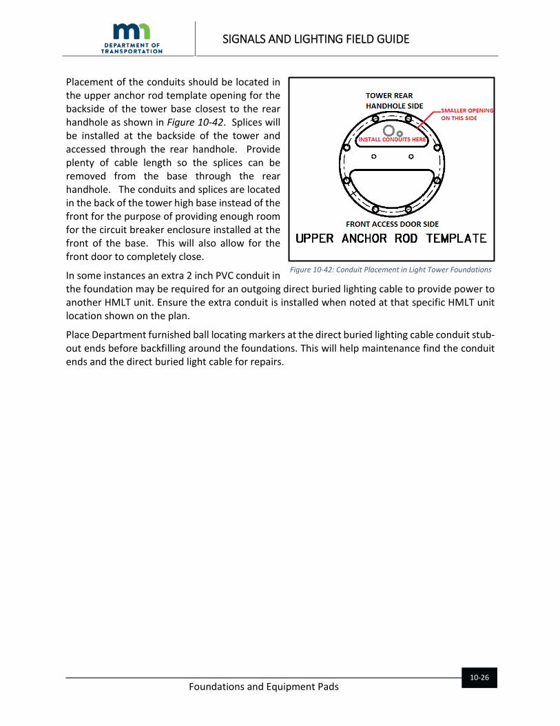
Placement of the conduits should be located in the upper anchor rod template opening for the backside of the tower base closest to the rear handhole as shown in Figure 10-42. Splices will be installed at the backside of the tower and accessed through the rear handhole. Provide plenty of cable length so the splices can be removed from the base through the rear handhole. The conduits and splices are located in the back of the tower high base instead of the front for the purpose of providing enough room for the circuit breaker enclosure installed at the front of the base. This will also allow for the front door to completely close.
In some instances an extra 2 inch PVC conduit in the foundation may be required for an outgoing direct buried lighting cable to provide power to another HMLT unit. Ensure the extra conduit is installed when noted at that specific HMLT unit location shown on the plan.
Place Department furnished ball locating markers at the direct buried lighting cable conduit stub-out ends before backfilling around the foundations. This will help maintenance find the conduit ends and the direct buried light cable for repairs.
Figure 10-42: Conduit Placement in Light Tower Foundations

SIGNALS AND LIGHTING FIELD GUIDE
Foundations and Equipment Pads
10-27
10.5.6. EQUIPMENT PAD B CAST IN-PLACE AND PRECAST (STANDARD PLATE 8106)
The most common equipment pad used on MnDOT lighting systems is the equipment pad B Standard Plate 8106. The pad is designed to support L1 and L2 lighting service cabinets.
The equipment pad can be either cast in-place or precast. For cast in-place pads use the anchor rods supplied with the service cabinet. For precast provide anchor rods as shown on the standard plate and insert in drilled holes in the pad with an approved epoxy adhesive used for the APS push button foundation found on MnDOT’s APL.
Do not use mechanical anchor bolts or concrete wedge anchors for cast in-place or precast pads.
The conduits must line up with the bottom openings of the cabinet. Altering the cabinet structure to fit the conduits will not be accepted.
Both types of equipment pads require two ground rod electrodes. The precast pad reinforcement bar is also bonded to ground. See Standard Plate 8106 for more details on Grounding Electrode System for the cast in-place and precast pads.
10.5.7. RLF EQUIPMENT PAD CAST IN-PLACE AND PRECAST (STANDARD PLATE 8107)
The RLF equipment pad is designed to support a Type Rural Lighting and Flasher (RLF) service cabinet.
The equipment pad can be either cast in-place or precast. For cast in-place pads use the anchor rods supplied with the service cabinet.
Figure 10-43: Equipment Pad B Details

SIGNALS AND LIGHTING FIELD GUIDE
Foundations and Equipment Pads
10-28
For precast use anchor rods shown on the precast standard plate. Insert the anchor rods into drilled holes in the pad with an approved epoxy adhesive used for the APS push button foundation found on MnDOT’s APL.
Do not use mechanical anchor bolts or concrete wedge anchors for cast in-place or precast pads. Do not wet cast anchors for precast pads.
A grounding system is required for both cast in-place and precast pads in accordance with 2545.3. Use the grounding system detail shown on sheet 3 of Standard Plate 8106 Equipment Pad B.
In the precast pad the two layers of rebar mat must be bonded together using a solid 6 AWG bare copper conductor. The copper conductor must be all one piece (no splices) with a minimum of 5 feet of exposed length out of the concrete from the 10 inch X 10-inch hole. This installation takes place at the precast facility.
Figure 10-44: RLF Equipment Pad Cast In-Place and Precast
SIGNALS AND LIGHTING FIELD GUIDE
Foundations and Equipment Pads
10-29
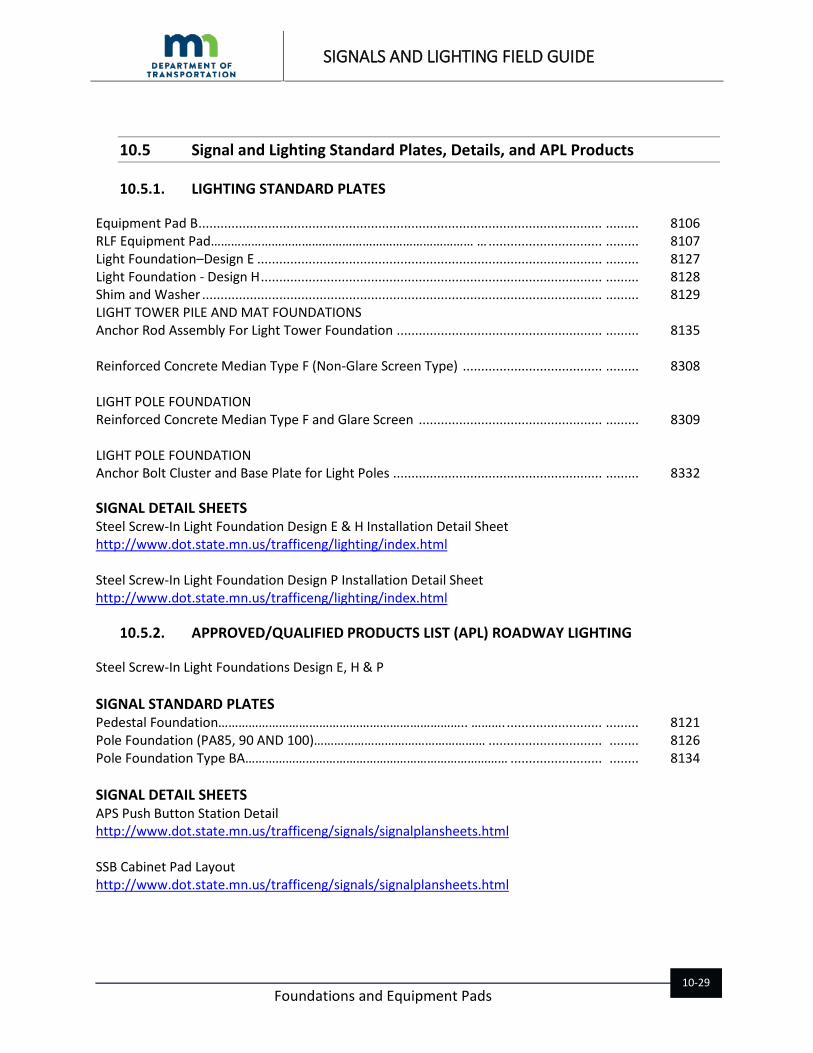
10.5 Signal and Lighting Standard Plates, Details, and APL Products
10.5.1. LIGHTING STANDARD PLATES
Equipment Pad B .............................................................................................................. ......... 8106 RLF Equipment Pad…………………………………………………………………… … ............................... ......... 8107 Light Foundation–Design E .............................................................................................. ......... 8127 Light Foundation - Design H ............................................................................................. ......... 8128 Shim and Washer ............................................................................................................. ......... 8129 LIGHT TOWER PILE AND MAT FOUNDATIONS Anchor Rod Assembly For Light Tower Foundation ........................................................ ......... 8135 Reinforced Concrete Median Type F (Non-Glare Screen Type) ...................................... ......... 8308 LIGHT POLE FOUNDATION Reinforced Concrete Median Type F and Glare Screen .................................................. ......... 8309
LIGHT POLE FOUNDATION Anchor Bolt Cluster and Base Plate for Light Poles ......................................................... ......... 8332
SIGNAL DETAIL SHEETS Steel Screw-In Light Foundation Design E & H Installation Detail Sheet http://www.dot.state.mn.us/trafficeng/lighting/index.html Steel Screw-In Light Foundation Design P Installation Detail Sheet http://www.dot.state.mn.us/trafficeng/lighting/index.html
10.5.2. APPROVED/QUALIFIED PRODUCTS LIST (APL) ROADWAY LIGHTING
Steel Screw-In Light Foundations Design E, H & P SIGNAL STANDARD PLATES Pedestal Foundation……………………………………………………………….. ………. .......................... ......... 8121 Pole Foundation (PA85, 90 AND 100)…………………………………………… ............................... ........ 8126 Pole Foundation Type BA…………………………………………………………………… ......................... ........ 8134 SIGNAL DETAIL SHEETS APS Push Button Station Detail http://www.dot.state.mn.us/trafficeng/signals/signalplansheets.html SSB Cabinet Pad Layout http://www.dot.state.mn.us/trafficeng/signals/signalplansheets.html

SIGNALS AND LIGHTING FIELD GUIDE
Foundations and Equipment Pads
10-30
10.6 Chapter 10 Resources
• MnDOT Approved/Qualified Products List (APL) • MnDOT Standard Specifications for Construction 2401, 2411, 2451, 2545.3, 2565.3, 3756,
3813, 3813, 3385, 3818 • Standard Plates (listed above) • Roadway Lighting Special Provisions