chapter 1: introduction - wiley.com · how to simulate/verify a design using verilog hdl. chapter1:...
TRANSCRIPT

Chapter1: Introduction
Digital System Designs and Practices Using Verilog HDL and FPGAs @ 2008~2010, John Wiley 1-1
Chapter 1: Introduction
Department of Electronic Engineering
National Taiwan University of Science and Technology
Prof. Ming-Bo Lin

Chapter1: Introduction
Digital System Designs and Practices Using Verilog HDL and FPGAs @ 2008~2010, John Wiley 1-2
Syllabus
ObjectivesIntroductionIntroduction to Verilog HDLModule modeling stylesSimulation

Chapter1: Introduction
Digital System Designs and Practices Using Verilog HDL and FPGAs @ 2008~2010, John Wiley 1-3
Objectives
After completing this chapter, you will be able to understand:The features of HDLs and Verilog HDLThe HDL-based design flowThe basic features of the modules in Verilog HDLHow to model a design in structural styleHow to model a design in dataflow styleHow to model a design in behavioral styleHow to model a design in mixed styleHow to simulate/verify a design using Verilog HDL

Chapter1: Introduction
Digital System Designs and Practices Using Verilog HDL and FPGAs @ 2008~2010, John Wiley 1-4
Syllabus
ObjectivesIntroduction
Introduction to Verilog HDLHDL-based design flow
Introduction to Verilog HDLModule modeling stylesSimulation

Chapter1: Introduction
Digital System Designs and Practices Using Verilog HDL and FPGAs @ 2008~2010, John Wiley 1-5
Importance of HDLsHDL: Hardware Description LanguageTwo commonly used HDLs
Verilog HDL (also called Verilog for short)VHDL (Very high-speed integrated circuits HDL)

Chapter1: Introduction
Digital System Designs and Practices Using Verilog HDL and FPGAs @ 2008~2010, John Wiley 1-6
Features of HDLs
Design can be described at a very abstract levelFunctional verification can be done early in the design cycleDesigning with HDLs is analogous to computer programming

Chapter1: Introduction
Digital System Designs and Practices Using Verilog HDL and FPGAs @ 2008~2010, John Wiley 1-7
Verilog HDL
A general-purpose, easy to learn, and easy to use HDL languageAllowing different levels of abstraction in the same moduleProgramming Language Interface (PLI)

Chapter1: Introduction
Digital System Designs and Practices Using Verilog HDL and FPGAs @ 2008~2010, John Wiley 1-8
Syllabus
ObjectivesIntroduction
Introduction to Verilog HDLHDL-based design flow
Introduction to Verilog HDLModule modeling stylesSimulation
Chapter1: Introduction
Digital System Designs and Practices Using Verilog HDL and FPGAs @ 2008~2010, John Wiley 1-9
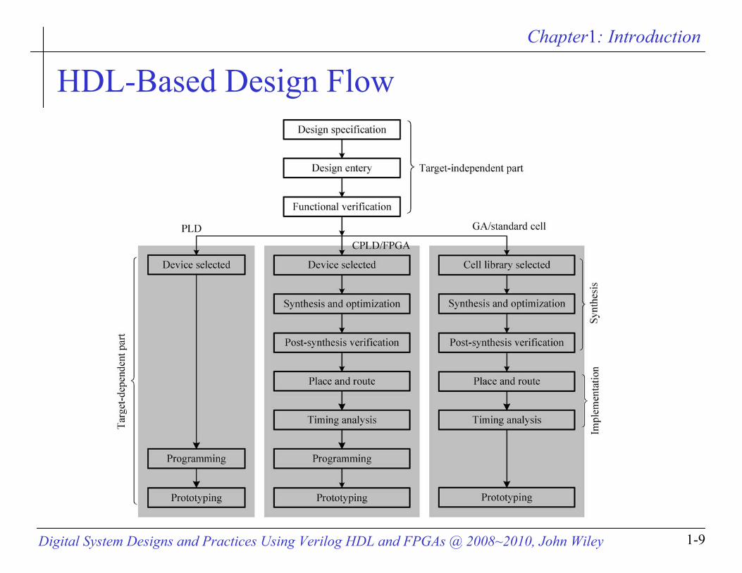
HDL-Based Design Flow
Chapter1: Introduction
Digital System Designs and Practices Using Verilog HDL and FPGAs @ 2008~2010, John Wiley 1-10
Syllabus
ObjectivesIntroductionIntroduction to Verilog HDL
Concept of moduleBasic syntaxData types
Module modeling stylesSimulation
Chapter1: Introduction
Digital System Designs and Practices Using Verilog HDL and FPGAs @ 2008~2010, John Wiley 1-11
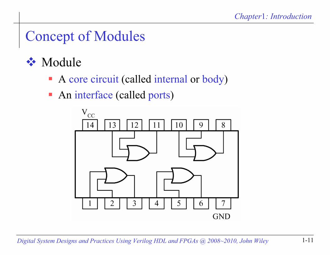
Concept of Modules
ModuleA core circuit (called internal or body) An interface (called ports)

Chapter1: Introduction
Digital System Designs and Practices Using Verilog HDL and FPGAs @ 2008~2010, John Wiley 1-12
Modules – Verilog HDL modules
module --- The basic building block

Chapter1: Introduction
Digital System Designs and Practices Using Verilog HDL and FPGAs @ 2008~2010, John Wiley 1-13
Syllabus
ObjectivesIntroductionIntroduction to Verilog HDL
Concept of moduleBasic syntaxData types
Module modeling stylesSimulation

Chapter1: Introduction
Digital System Designs and Practices Using Verilog HDL and FPGAs @ 2008~2010, John Wiley 1-14
Lexical Conventions
Almost the same lexical conventions as C languageIdentifiers: alphanumeric characters, _, and $
Verilog is a case-sensitive language White space: blank space (\b), tabs (\t), and new line (\n)

Chapter1: Introduction
Digital System Designs and Practices Using Verilog HDL and FPGAs @ 2008~2010, John Wiley 1-15
Lexical Conventions
Comments// --- the remaining of the line /* ….*/ --- what in between them
Sized number: <size>`<base format><number>4`b1001 16`habcd
Chapter1: Introduction
Digital System Designs and Practices Using Verilog HDL and FPGAs @ 2008~2010, John Wiley 1-16
Lexical Conventions
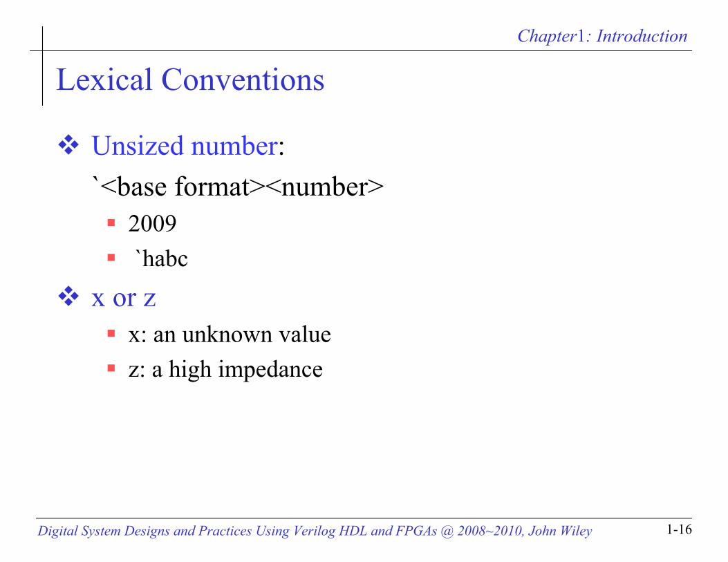
Unsized number: `<base format><number>
2009 `habc
x or zx: an unknown valuez: a high impedance

Chapter1: Introduction
Digital System Designs and Practices Using Verilog HDL and FPGAs @ 2008~2010, John Wiley 1-17
Lexical Conventions
Negative number: -<size>`<base format><number>
-4`b1001 -16`habcd
”_” and “?”16`b0101_1001_1110_0000 8`b01??_11?? // = 8`b01zz_11zz
String: “Have a lovely day”

Chapter1: Introduction
Digital System Designs and Practices Using Verilog HDL and FPGAs @ 2008~2010, John Wiley 1-18
Coding Style
Lowercase lettersFor all signal names, variable names, and port names
Uppercase lettersFor names of constants and user-defined types
Meaningful names For signals, ports, functions, and parameters

Chapter1: Introduction
Digital System Designs and Practices Using Verilog HDL and FPGAs @ 2008~2010, John Wiley 1-19
The Value Set
Four-value logic 0 : logic 0, false condition1 : logic 1, true conditionz : high-impedancex : unknown
Chapter1: Introduction
Digital System Designs and Practices Using Verilog HDL and FPGAs @ 2008~2010, John Wiley 1-20
Syllabus
ObjectivesIntroductionIntroduction to Verilog HDL
Concept of moduleBasic syntaxData types
Module modeling stylesSimulation

Chapter1: Introduction
Digital System Designs and Practices Using Verilog HDL and FPGAs @ 2008~2010, John Wiley 1-21
Data Types
Nets: any hardware connection pointsVariables: any data storage elements

Chapter1: Introduction
Digital System Designs and Practices Using Verilog HDL and FPGAs @ 2008~2010, John Wiley 1-22
Nets
Driven by Primitivecontinuous assignmentforce … releasemodule port

Chapter1: Introduction
Digital System Designs and Practices Using Verilog HDL and FPGAs @ 2008~2010, John Wiley 1-23
Variables
Assigned value only within Procedural statementTaskFunction
Cannot be used asinput inout

Chapter1: Introduction
Digital System Designs and Practices Using Verilog HDL and FPGAs @ 2008~2010, John Wiley 1-24
Syllabus
ObjectivesIntroductionIntroduction to Verilog HDLModule modeling styles
IntroductionStructural styleDataflow styleBehavioral styleMixed style
Simulation

Chapter1: Introduction
Digital System Designs and Practices Using Verilog HDL and FPGAs @ 2008~2010, John Wiley 1-25
Module Modeling Styles
Structural styleGate levelSwitch level
Dataflow styleBehavioral or algorithmic styleMixed style
RTL = synthesizable behavioral + dataflow constructs

Chapter1: Introduction
Digital System Designs and Practices Using Verilog HDL and FPGAs @ 2008~2010, John Wiley 1-26
Syllabus
ObjectivesIntroductionIntroduction to Verilog HDLModule modeling styles
IntroductionStructural styleDataflow styleBehavioral styleMixed style
Simulation
Chapter1: Introduction
Digital System Designs and Practices Using Verilog HDL and FPGAs @ 2008~2010, John Wiley 1-27
Port Declaration
Types of portsinputoutputinout
Chapter1: Introduction
Digital System Designs and Practices Using Verilog HDL and FPGAs @ 2008~2010, John Wiley 1-28
Port Connection Rules
Named associationPositional association
Chapter1: Introduction
Digital System Designs and Practices Using Verilog HDL and FPGAs @ 2008~2010, John Wiley 1-29
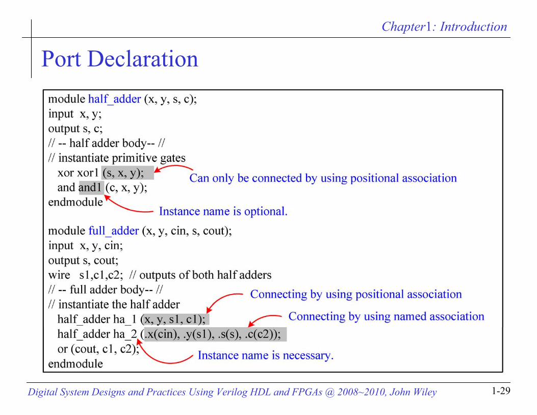
Port Declaration

Chapter1: Introduction
Digital System Designs and Practices Using Verilog HDL and FPGAs @ 2008~2010, John Wiley 1-30
Structural modeling
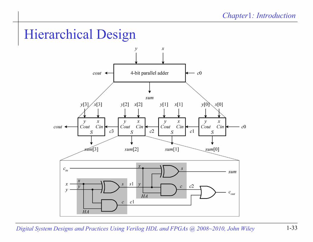
// gate-level hierarchical description of 4-bit adder// gate-level description of half addermodule half_adder (x, y, s, c);input x, y;output s, c;// half adder body// instantiate primitive gatesxor (s,x,y);and (c,x,y);endmodule

Chapter1: Introduction
Digital System Designs and Practices Using Verilog HDL and FPGAs @ 2008~2010, John Wiley 1-31
Structural modeling
// gate-level description of full addermodule full_adder (x, y, cin, s, cout);input x, y, cin;output s, cout;wire s1, c1, c2; // outputs of both half adders// full adder body// instantiate the half adderhalf_adder ha_1 (x, y, s1, c1);half_adder ha_2 (cin, s1, s, c2);or (cout, c1, c2);endmodule

Chapter1: Introduction
Digital System Designs and Practices Using Verilog HDL and FPGAs @ 2008~2010, John Wiley 1-32
Structural modeling// gate-level description of 4-bit addermodule four_bit_adder (x, y, c_in, sum, c_out);input [3:0] x, y;input c_in;output [3:0] sum;output c_out;wire c1, c2, c3; // intermediate carries// four_bit adder body// instantiate the full adderfull_adder fa_1 (x[0], y[0], c_in, sum[0], c1);full_adder fa_2 (x[1], y[1], c1, sum[1], c2);full_adder fa_3 (x[2], y[2], c2, sum[2], c3);full_adder fa_4 (x[3], y[3], c3, sum[3], c_out);endmodule
Chapter1: Introduction
Digital System Designs and Practices Using Verilog HDL and FPGAs @ 2008~2010, John Wiley 1-33
Hierarchical Design

Chapter1: Introduction
Digital System Designs and Practices Using Verilog HDL and FPGAs @ 2008~2010, John Wiley 1-34
Syllabus
ObjectivesIntroductionIntroduction to Verilog HDLModule modeling styles
IntroductionStructural styleDataflow styleBehavioral styleMixed style
Simulation

Chapter1: Introduction
Digital System Designs and Practices Using Verilog HDL and FPGAs @ 2008~2010, John Wiley 1-35
Dataflow Modeling
module full_adder_dataflow(x, y, c_in, sum, c_out);// I/O port declarationsinput x, y, c_in;output sum, c_out;// specify the function of a full adderassign #5 {c_out, sum} = x + y + c_in;endmodule
Chapter1: Introduction
Digital System Designs and Practices Using Verilog HDL and FPGAs @ 2008~2010, John Wiley 1-36
Syllabus
ObjectivesIntroductionIntroduction to Verilog HDLModule modeling styles
IntroductionStructural styleDataflow styleBehavioral styleMixed style
Simulation

Chapter1: Introduction
Digital System Designs and Practices Using Verilog HDL and FPGAs @ 2008~2010, John Wiley 1-37
Behavioral Modeling
module full_adder_behavioral(x, y, c_in, sum, c_out);// I/O port declarationsinput x, y, c_in;output sum, c_out;reg sum, c_out; // need to be declared as reg types// specify the function of a full adderalways @(x, y, c_in) // always @(*) or always@(x or y or c_in)#5 {c_out, sum} = x + y + c_in;endmodule
Chapter1: Introduction
Digital System Designs and Practices Using Verilog HDL and FPGAs @ 2008~2010, John Wiley 1-38
Syllabus
ObjectivesIntroductionIntroduction to Verilog HDLModule modeling styles
IntroductionStructural styleDataflow styleBehavioral styleMixed style
Simulation

Chapter1: Introduction
Digital System Designs and Practices Using Verilog HDL and FPGAs @ 2008~2010, John Wiley 1-39
Mixed-Style Modelingmodule full_adder_mixed_style(x, y, c_in, s, c_out);// I/O port declarationsinput x, y, c_in;output s, c_out;reg c_out;wire s1, c1, c2;// structural modeling of HA 1xor xor_ha1 (s1, x, y);and and_ha1(c1, x, y);// dataflow modeling of HA 2assign s = c_in ^ s1;assign c2 = c_in & s1;// behavioral modeling of output OR gatealways @(c1, c2) // always @(*)c_out = c1 | c2;endmodule

Chapter1: Introduction
Digital System Designs and Practices Using Verilog HDL and FPGAs @ 2008~2010, John Wiley 1-40
Syllabus
ObjectivesIntroductionIntroduction to Verilog HDLModule modeling stylesSimulation
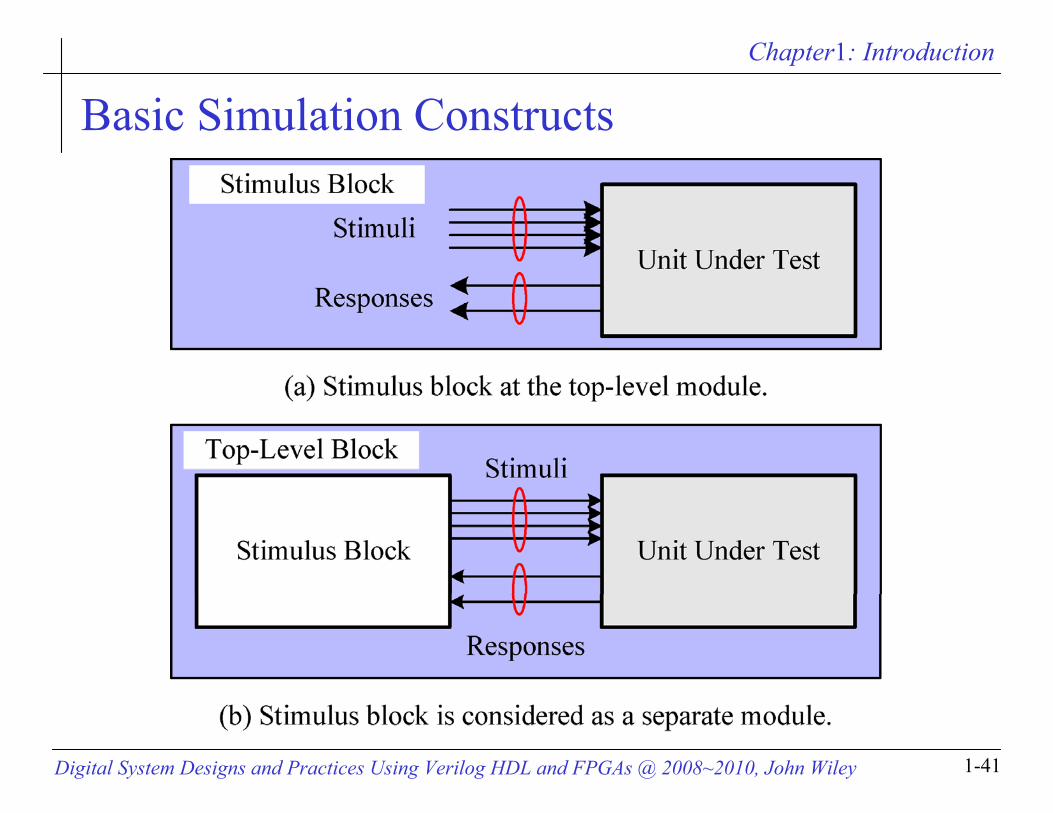
Basic simulation constructsSystem tasksAn example
Chapter1: Introduction
Digital System Designs and Practices Using Verilog HDL and FPGAs @ 2008~2010, John Wiley 1-41
Basic Simulation Constructs
Chapter1: Introduction
Digital System Designs and Practices Using Verilog HDL and FPGAs @ 2008~2010, John Wiley 1-42
Syllabus
ObjectivesIntroductionIntroduction to Verilog HDLModule modeling stylesSimulation
Basic simulation constructsSystem tasksAn example

Chapter1: Introduction
Digital System Designs and Practices Using Verilog HDL and FPGAs @ 2008~2010, John Wiley 1-43
System Tasks for Simulation$display
$display(ep1, ep2, …, epn); ep1, ep2, …, epn: quoted strings, variables, expressions
$monitor $monitor(ep1, ep2, …, epn);
$monitoton$monitotoff$stop$finish
Chapter1: Introduction
Digital System Designs and Practices Using Verilog HDL and FPGAs @ 2008~2010, John Wiley 1-44
Time Scale for Simulations
Time scale compiler directive `timescale time_unit / time_precision

Chapter1: Introduction
Digital System Designs and Practices Using Verilog HDL and FPGAs @ 2008~2010, John Wiley 1-45
Syllabus
ObjectivesIntroductionIntroduction to Verilog HDLModule modeling stylesSimulation
Basic simulation constructsSystem tasksAn example
Chapter1: Introduction
Digital System Designs and Practices Using Verilog HDL and FPGAs @ 2008~2010, John Wiley 1-46
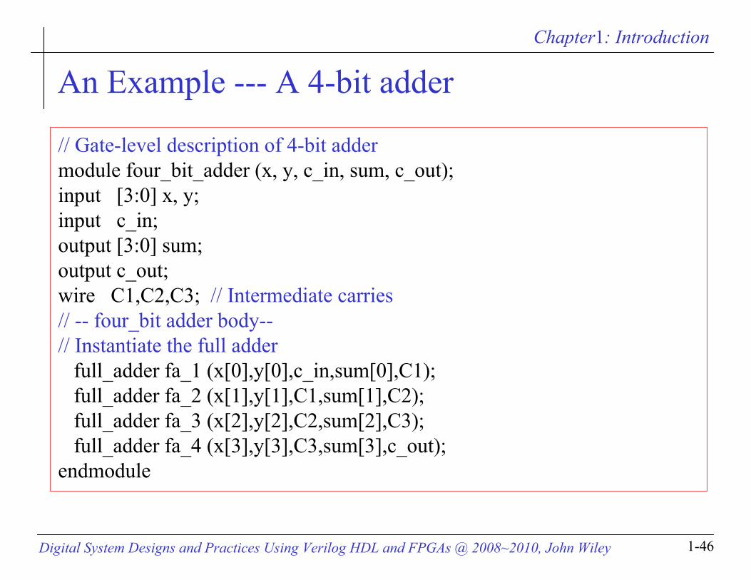
An Example --- A 4-bit adder
// Gate-level description of 4-bit adder module four_bit_adder (x, y, c_in, sum, c_out);input [3:0] x, y;input c_in;output [3:0] sum;output c_out;wire C1,C2,C3; // Intermediate carries// -- four_bit adder body--// Instantiate the full adder
full_adder fa_1 (x[0],y[0],c_in,sum[0],C1);full_adder fa_2 (x[1],y[1],C1,sum[1],C2);full_adder fa_3 (x[2],y[2],C2,sum[2],C3);full_adder fa_4 (x[3],y[3],C3,sum[3],c_out);
endmodule

Chapter1: Introduction
Digital System Designs and Practices Using Verilog HDL and FPGAs @ 2008~2010, John Wiley 1-47
An Example --- A 4-bit adder

Chapter1: Introduction
Digital System Designs and Practices Using Verilog HDL and FPGAs @ 2008~2010, John Wiley 1-48
An Example --- A Test Bench
`timescale 1 ns / 100 ps // time unit is in ns.module four_bit_adder_tb;//Internal signals declarations:reg [3:0] x;reg [3:0] y;reg c_in;wire [3:0] sum;wire c_out;// Unit Under Test port map
four_bit_adder UUT (.x(x), .y(y), .c_in(c_in), .sum(sum), .c_out(c_out));reg [7:0] i;initial begin // for use in post-map and post-par simulations.// $sdf_annotate ("four_bit_adder_map.sdf", four_bit_adder);// $sdf_annotate ("four_bit_adder_timesim.sdf", four_bit_adder);end

Chapter1: Introduction
Digital System Designs and Practices Using Verilog HDL and FPGAs @ 2008~2010, John Wiley 1-49
An Example --- A Test Bench
initial for (i = 0; i <= 255; i = i + 1) begin
x[3:0] = i[7:4]; y[3:0] = i[3:0]; c_in =1'b0;#20 ; end
initial #6000 $finish;initial
$monitor($realtime,“ns %h %h %h %h", x, y, c_in, {c_out, sum});endmodule

Chapter1: Introduction
Digital System Designs and Practices Using Verilog HDL and FPGAs @ 2008~2010, John Wiley 1-50
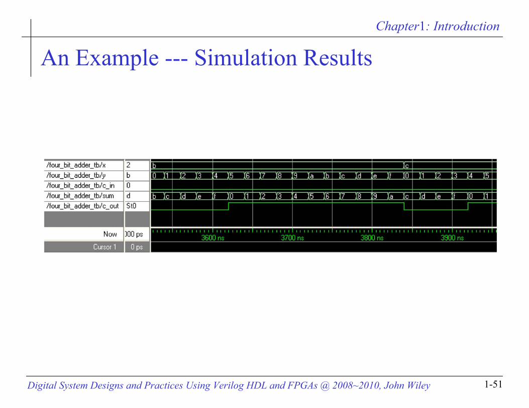
An Example --- Simulation Results
0ns 0 0 0 00# 20ns 0 1 0 01# 40ns 0 2 0 02# 60ns 0 3 0 03# 80ns 0 4 0 04# 100ns 0 5 0 05# 120ns 0 6 0 06# 140ns 0 7 0 07# 160ns 0 8 0 08# 180ns 0 9 0 09# 200ns 0 a 0 0a# 220ns 0 b 0 0b# 240ns 0 c 0 0c# 260ns 0 d 0 0d
# 280ns 0 e 0 0e# 300ns 0 f 0 0f# 320ns 1 0 0 01# 340ns 1 1 0 02# 360ns 1 2 0 03# 380ns 1 3 0 04# 400ns 1 4 0 05# 420ns 1 5 0 06# 440ns 1 6 0 07# 460ns 1 7 0 08# 480ns 1 8 0 09# 500ns 1 9 0 0a# 520ns 1 a 0 0b# 540ns 1 b 0 0c
Chapter1: Introduction
Digital System Designs and Practices Using Verilog HDL and FPGAs @ 2008~2010, John Wiley 1-51
An Example --- Simulation Results