verilog hdl introduction - androbench
TRANSCRIPT
EEE3050 Theory on Computer Architectures (Spring 2017)Prof. Jinkyu Jeong
Verilog HDL Introduction2017.05.14
TA 이규선(GYUSUN LEE) / 안민우(MINWOO AHN)
Computer Systems Laboratory

Modules The Module Concept◦ Basic design unit
◦ Modules are:◦ Declared
◦ Instantiated
◦ Modules declarations cannot be nested
2Computer Systems Laboratory
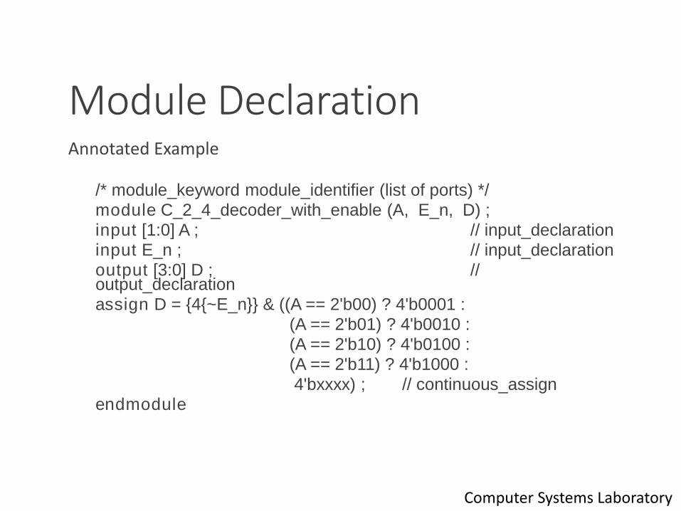
Module DeclarationAnnotated Example
/* module_keyword module_identifier (list of ports) */
module C_2_4_decoder_with_enable (A, E_n, D) ;
input [1:0] A ; // input_declaration
input E_n ; // input_declaration
output [3:0] D ; // output_declaration
assign D = {4{~E_n}} & ((A == 2'b00) ? 4'b0001 :
(A == 2'b01) ? 4'b0010 :
(A == 2'b10) ? 4'b0100 :
(A == 2'b11) ? 4'b1000 :
4'bxxxx) ; // continuous_assign
endmodule
3Computer Systems Laboratory
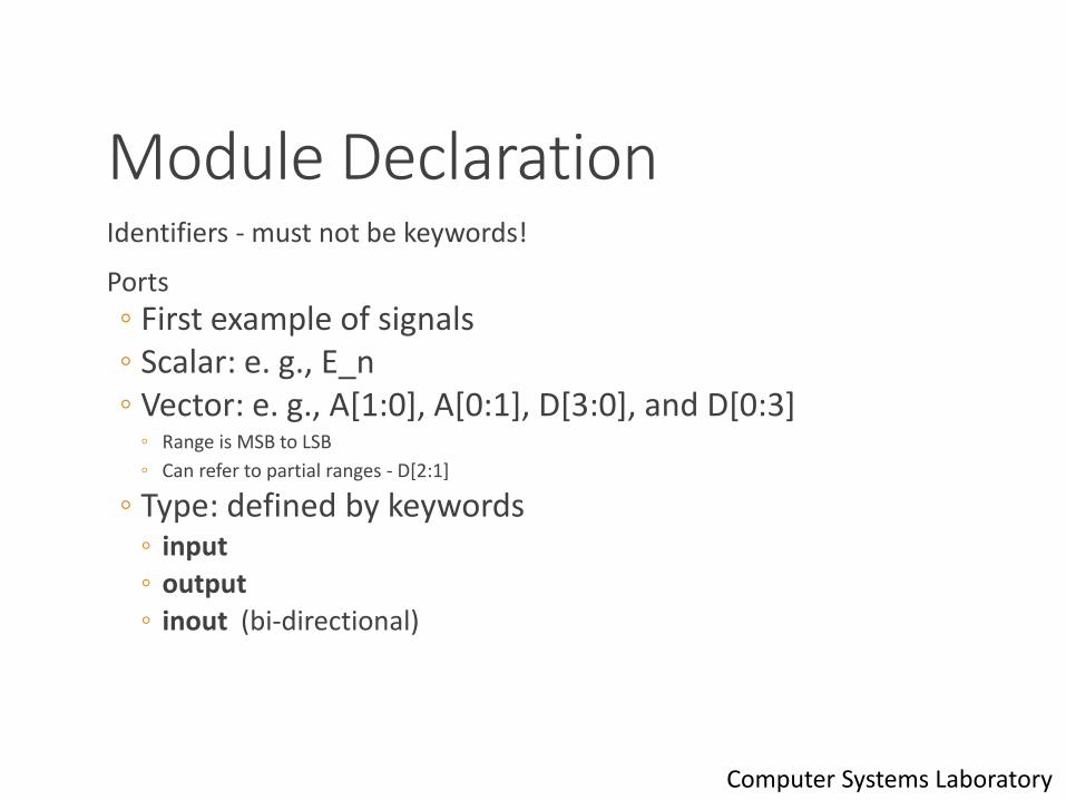
Module DeclarationIdentifiers - must not be keywords!
Ports
◦ First example of signals ◦ Scalar: e. g., E_n◦ Vector: e. g., A[1:0], A[0:1], D[3:0], and D[0:3]
◦ Range is MSB to LSB
◦ Can refer to partial ranges - D[2:1]
◦ Type: defined by keywords◦ input
◦ output
◦ inout (bi-directional)
4Computer Systems Laboratory

Module Instantiation
5
module C_4_16_decoder_with_enable (A, E_n, D) ;
input [3:0] A ; input E_n ; output [15:0] D ;
wire [3:0] S;wire [3:0] S_n;
C_2_4_decoder_with_enable DE (A[3:2], E_n, S);not N0 (S_n, S);C_2_4_decoder_with_enable D0 (A[1:0], S_n[0], D[3:0]);C_2_4_decoder_with_enable D1 (A[1:0], S_n[1], D[7:4]);C_2_4_decoder_with_enable D2 (A[1:0], S_n[2], D[11:8]);C_2_4_decoder_with_enable D3 (A[1:0], S_n[3], D[15:12]);
endmodule
▪ Example
Computer Systems Laboratory
Module Instantiation
6
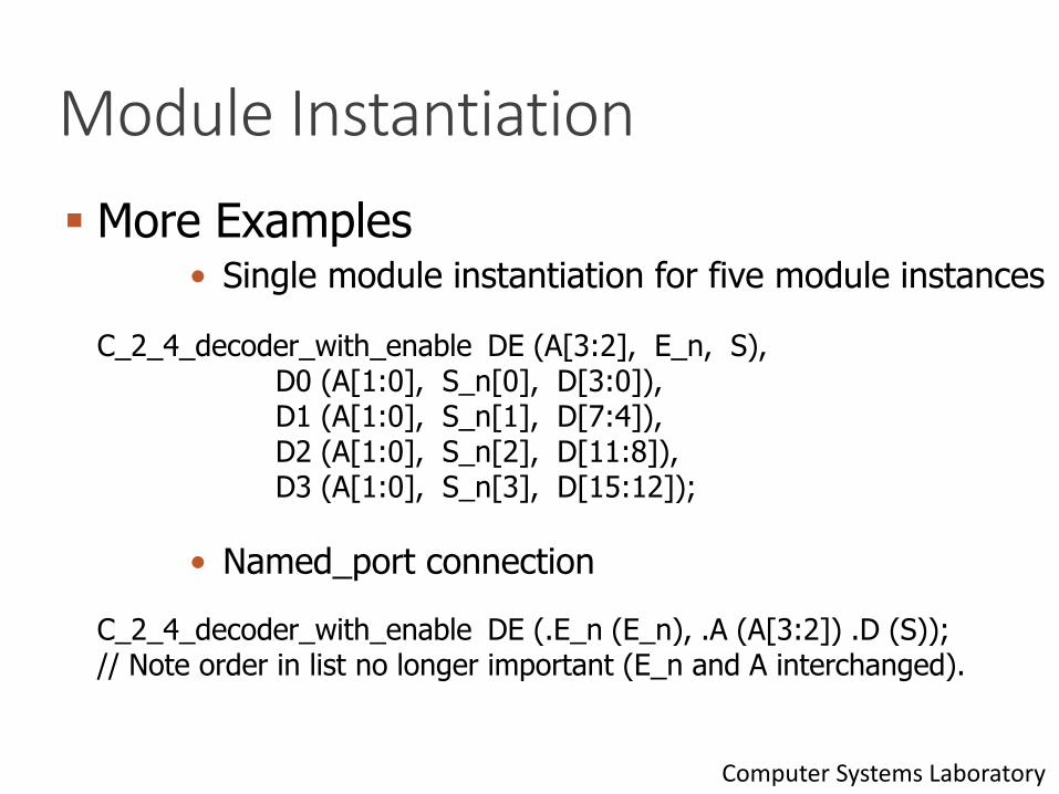
• Single module instantiation for five module instances
C_2_4_decoder_with_enable DE (A[3:2], E_n, S),D0 (A[1:0], S_n[0], D[3:0]),D1 (A[1:0], S_n[1], D[7:4]),D2 (A[1:0], S_n[2], D[11:8]),D3 (A[1:0], S_n[3], D[15:12]);
• Named_port connection
C_2_4_decoder_with_enable DE (.E_n (E_n), .A (A[3:2]) .D (S));// Note order in list no longer important (E_n and A interchanged).
▪ More Examples
Computer Systems Laboratory
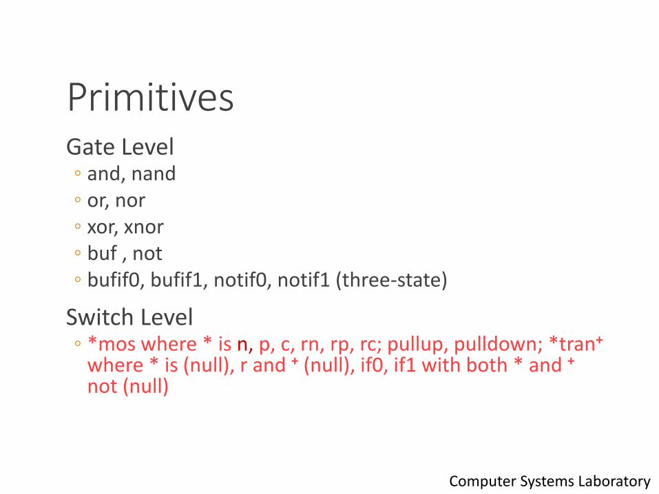
PrimitivesGate Level◦ and, nand◦ or, nor◦ xor, xnor◦ buf , not◦ bufif0, bufif1, notif0, notif1 (three-state)
Switch Level◦ *mos where * is n, p, c, rn, rp, rc; pullup, pulldown; *tran+
where * is (null), r and + (null), if0, if1 with both * and +
not (null)
7Computer Systems Laboratory
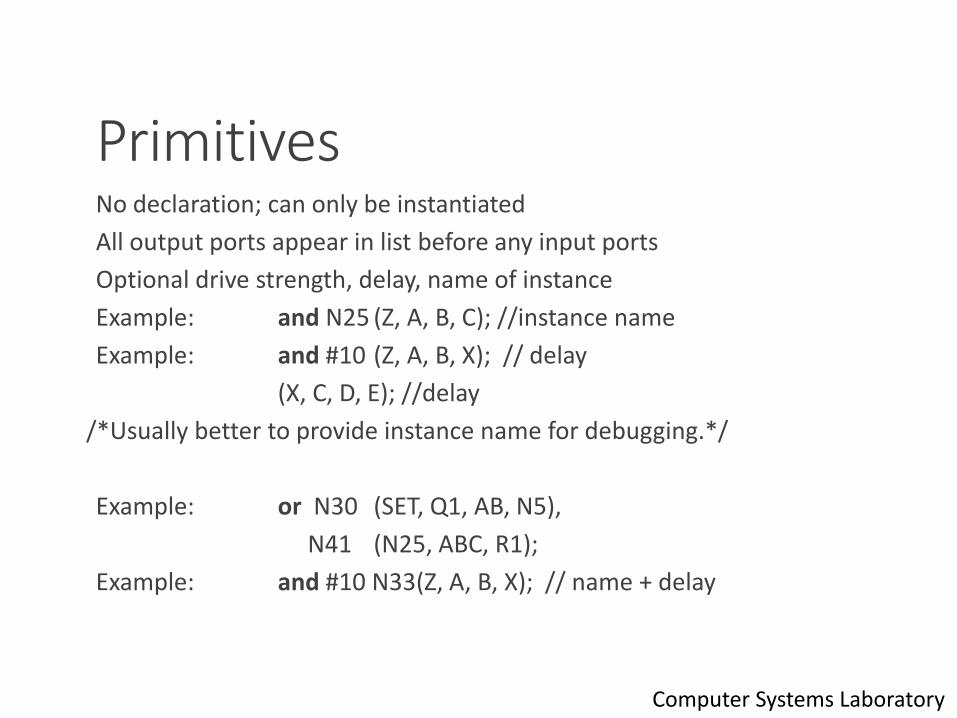
PrimitivesNo declaration; can only be instantiated
All output ports appear in list before any input ports
Optional drive strength, delay, name of instance
Example: and N25 (Z, A, B, C); //instance name
Example: and #10 (Z, A, B, X); // delay
(X, C, D, E); //delay
/*Usually better to provide instance name for debugging.*/
Example: or N30 (SET, Q1, AB, N5),
N41 (N25, ABC, R1);
Example: and #10 N33(Z, A, B, X); // name + delay
8Computer Systems Laboratory

StylesStructural - instantiation of primitives and modules
RTL/Dataflow - continuous assignments
Behavioral - procedural assignments
9Computer Systems Laboratory
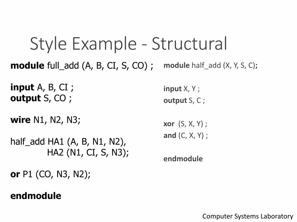
Style Example - Structuralmodule half_add (X, Y, S, C);
input X, Y ;
output S, C ;
xor (S, X, Y) ;
and (C, X, Y) ;
endmodule
10
module full_add (A, B, CI, S, CO) ;
input A, B, CI ;output S, CO ;
wire N1, N2, N3;
half_add HA1 (A, B, N1, N2),HA2 (N1, CI, S, N3);
or P1 (CO, N3, N2);
endmodule
Computer Systems Laboratory

Style Example - RTL/Dataflow
11
module fa_rtl (A, B, CI, S, CO) ;
input A, B, CI ;output S, CO ;
assign S = A ^ B ^ CI; //continuous assignmentassign CO = A & B | A & CI | B & CI; //continuous assignment
endmodule
Computer Systems Laboratory
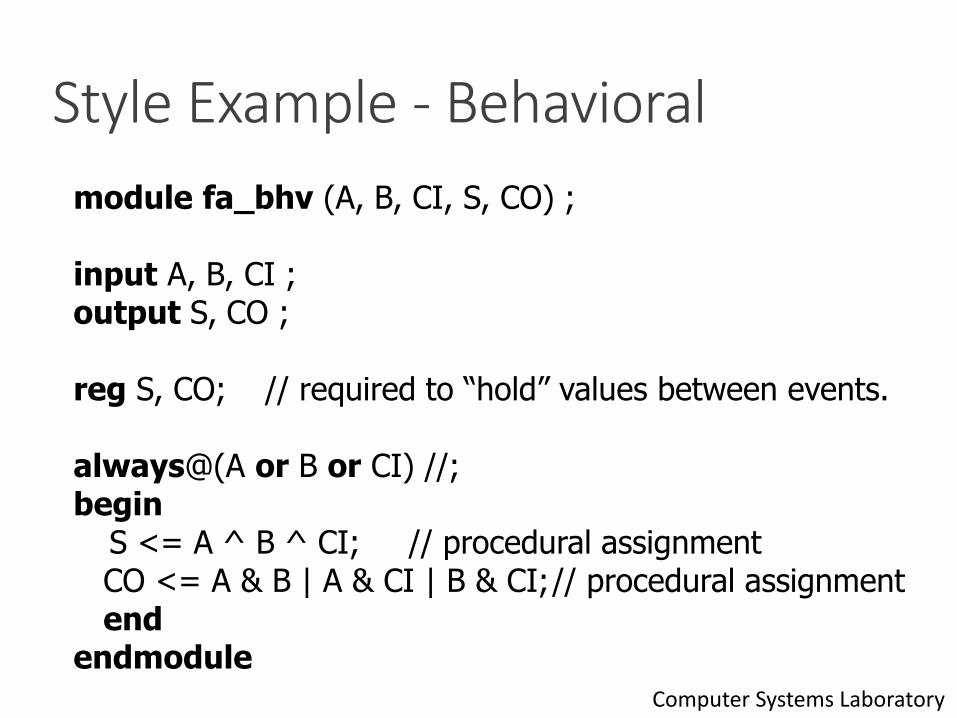
Style Example - Behavioral
12
module fa_bhv (A, B, CI, S, CO) ;
input A, B, CI ;output S, CO ;
reg S, CO; // required to “hold” values between events.
always@(A or B or CI) //; begin
S <= A ^ B ^ CI; // procedural assignmentCO <= A & B | A & CI | B & CI;// procedural assignment end
endmodule Computer Systems Laboratory
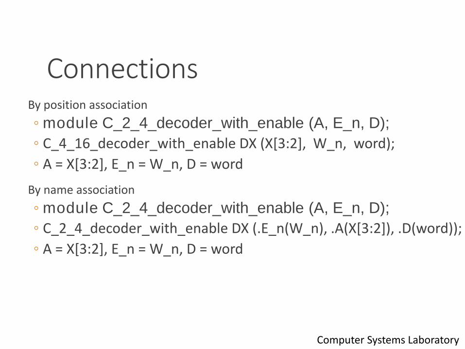
ConnectionsBy position association
◦ module C_2_4_decoder_with_enable (A, E_n, D);
◦ C_4_16_decoder_with_enable DX (X[3:2], W_n, word);
◦ A = X[3:2], E_n = W_n, D = word
By name association
◦ module C_2_4_decoder_with_enable (A, E_n, D);
◦ C_2_4_decoder_with_enable DX (.E_n(W_n), .A(X[3:2]), .D(word));
◦ A = X[3:2], E_n = W_n, D = word
13Computer Systems Laboratory
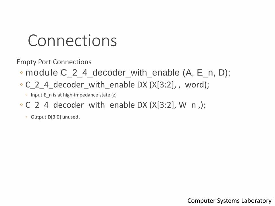
ConnectionsEmpty Port Connections
◦ module C_2_4_decoder_with_enable (A, E_n, D);
◦ C_2_4_decoder_with_enable DX (X[3:2], , word);◦ Input E_n is at high-impedance state (z)
◦ C_2_4_decoder_with_enable DX (X[3:2], W_n ,);◦ Output D[3:0] unused.
14Computer Systems Laboratory
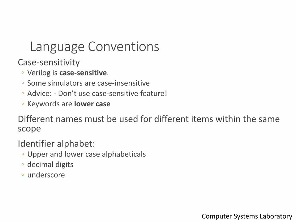
Language ConventionsCase-sensitivity◦ Verilog is case-sensitive.
◦ Some simulators are case-insensitive
◦ Advice: - Don’t use case-sensitive feature!
◦ Keywords are lower case
Different names must be used for different items within the same scope
Identifier alphabet:◦ Upper and lower case alphabeticals
◦ decimal digits
◦ underscore
15Computer Systems Laboratory

Language ConventionsMaximum of 1024 characters in identifier
First character not a digit
Statement terminated by ;
Free format within statement except for within quotes◦ Strings enclosed in double quotes and must be on a single line
Comments:◦ All characters after // in a line are treated as a comment
◦ Multi-line comments begin with /* and end with */
Compiler directives begin with // synopsys
Built-in system tasks or functions begin with $
16Computer Systems Laboratory
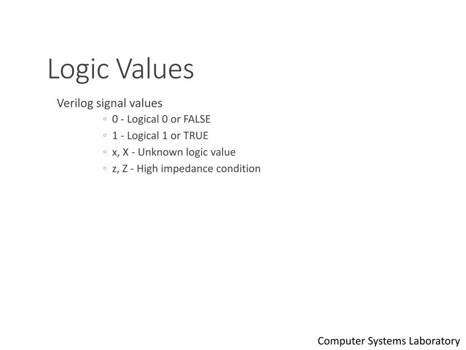
Logic ValuesVerilog signal values
◦ 0 - Logical 0 or FALSE
◦ 1 - Logical 1 or TRUE
◦ x, X - Unknown logic value
◦ z, Z - High impedance condition
17Computer Systems Laboratory
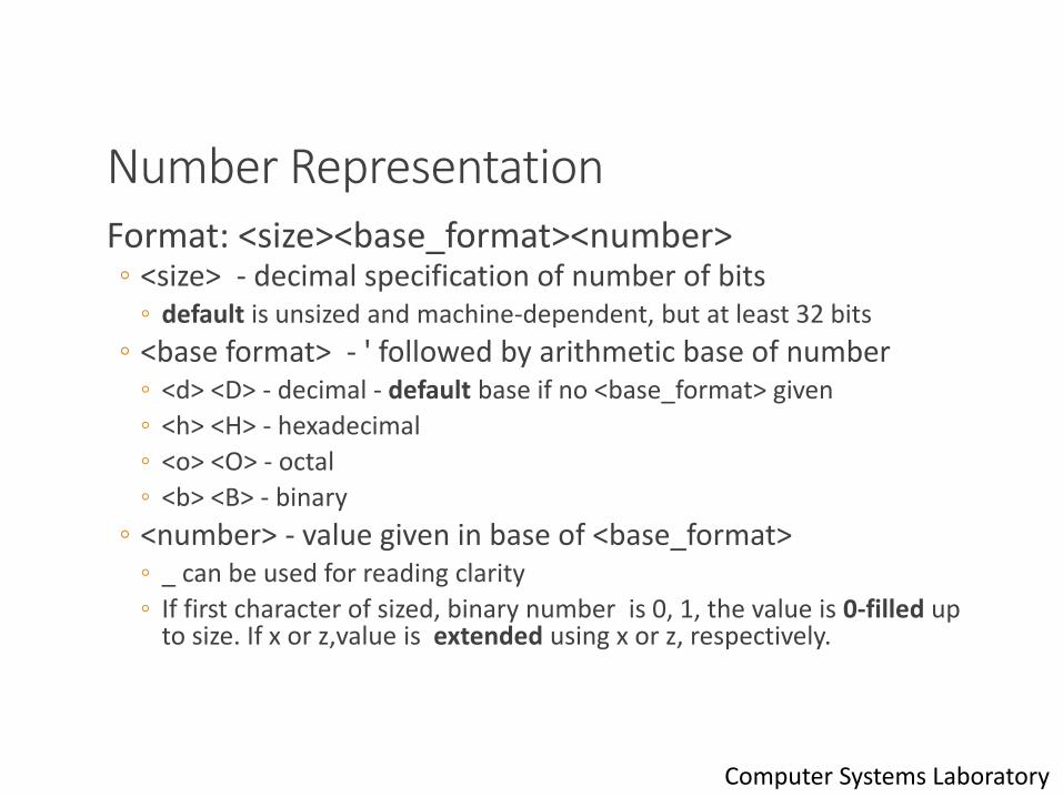
Number RepresentationFormat: <size><base_format><number>◦ <size> - decimal specification of number of bits
◦ default is unsized and machine-dependent, but at least 32 bits
◦ <base format> - ' followed by arithmetic base of number◦ <d> <D> - decimal - default base if no <base_format> given
◦ <h> <H> - hexadecimal
◦ <o> <O> - octal
◦ <b> <B> - binary
◦ <number> - value given in base of <base_format>◦ _ can be used for reading clarity
◦ If first character of sized, binary number is 0, 1, the value is 0-filled up to size. If x or z,value is extended using x or z, respectively.
18Computer Systems Laboratory

Number RepresentationExamples:◦ 6’b010_111 gives 010111◦ 8’b0110 gives 00000110◦ 8’b1110 gives 00001110◦ 4’bx01 gives xx01◦ 16’H3AB gives 0000001110101011◦ 24 gives 0…0011000◦ 5’O36 gives 11100◦ 16’Hx gives xxxxxxxxxxxxxxxx◦ 8’hz gives zzzzzzzz
19Computer Systems Laboratory
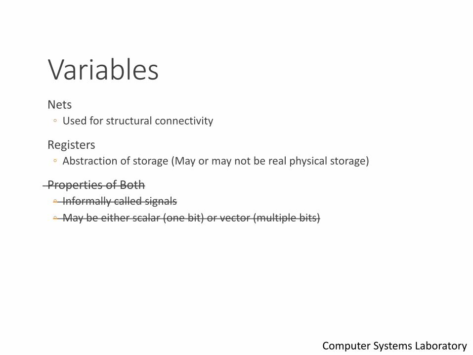
Variables Nets
◦ Used for structural connectivity
Registers◦ Abstraction of storage (May or may not be real physical storage)
Properties of Both◦ Informally called signals
◦ May be either scalar (one bit) or vector (multiple bits)
20Computer Systems Laboratory
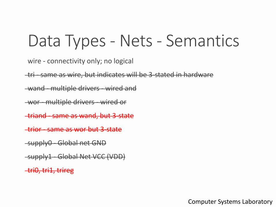
Data Types - Nets - Semantics wire - connectivity only; no logical
tri - same as wire, but indicates will be 3-stated in hardware
wand - multiple drivers - wired and
wor - multiple drivers - wired or
triand - same as wand, but 3-state
trior - same as wor but 3-state
supply0 - Global net GND
supply1 - Global Net VCC (VDD)
tri0, tri1, trireg
21Computer Systems Laboratory
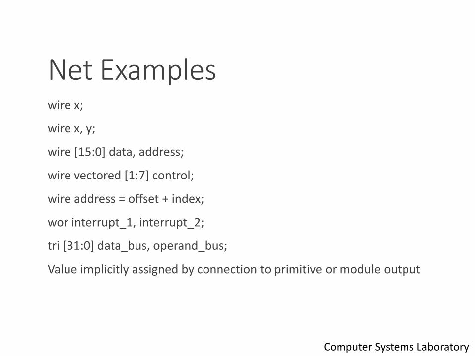
Net Examples wire x;
wire x, y;
wire [15:0] data, address;
wire vectored [1:7] control;
wire address = offset + index;
wor interrupt_1, interrupt_2;
tri [31:0] data_bus, operand_bus;
Value implicitly assigned by connection to primitive or module output
22Computer Systems Laboratory
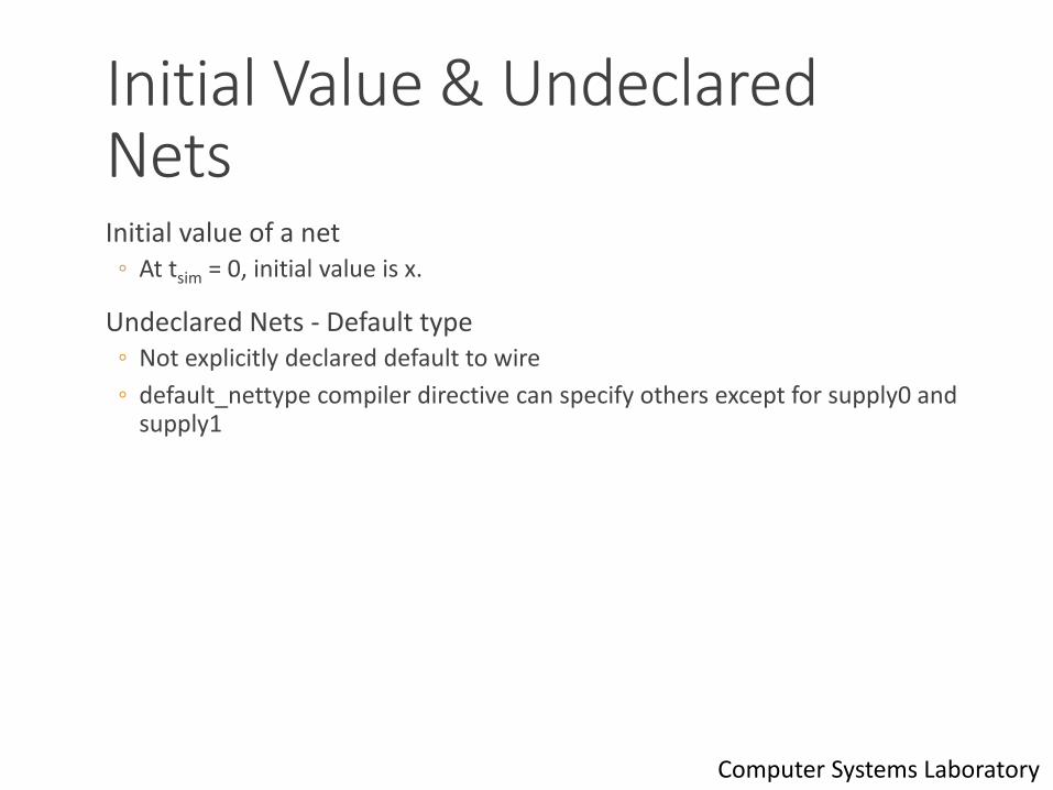
Initial Value & Undeclared NetsInitial value of a net
◦ At tsim = 0, initial value is x.
Undeclared Nets - Default type◦ Not explicitly declared default to wire
◦ default_nettype compiler directive can specify others except for supply0 and supply1
23Computer Systems Laboratory
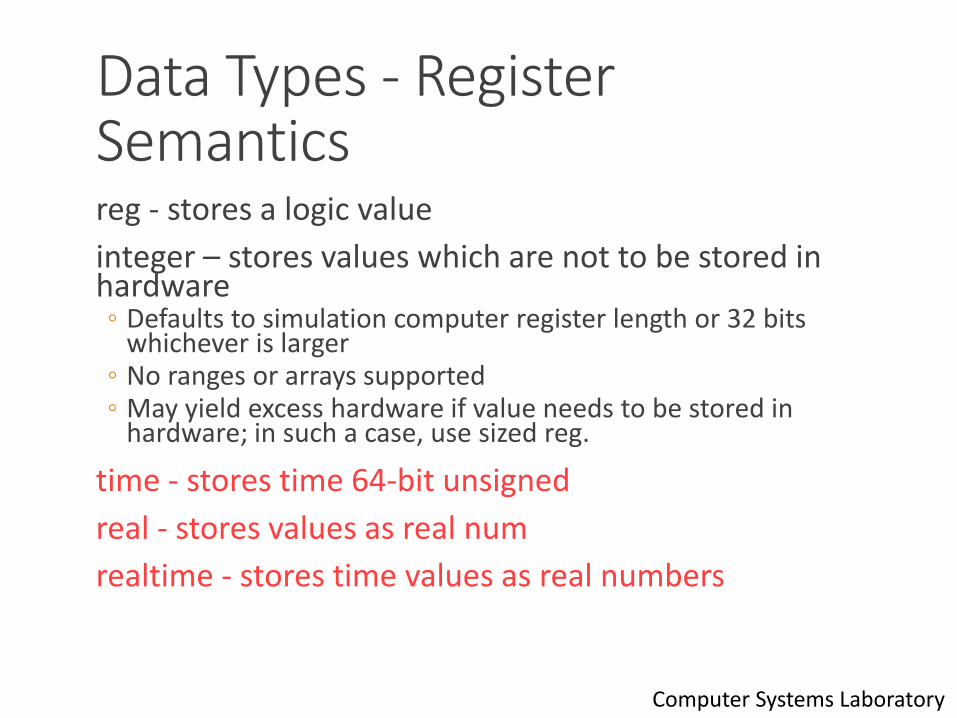
Data Types - Register Semanticsreg - stores a logic value
integer – stores values which are not to be stored in hardware◦ Defaults to simulation computer register length or 32 bits
whichever is larger◦ No ranges or arrays supported◦ May yield excess hardware if value needs to be stored in
hardware; in such a case, use sized reg.
time - stores time 64-bit unsigned
real - stores values as real num
realtime - stores time values as real numbers
24Computer Systems Laboratory
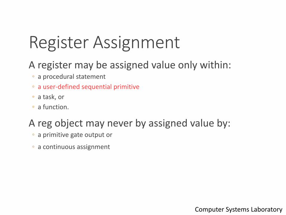
Register AssignmentA register may be assigned value only within:
◦ a procedural statement
◦ a user-defined sequential primitive
◦ a task, or
◦ a function.
A reg object may never by assigned value by:◦ a primitive gate output or
◦ a continuous assignment
25Computer Systems Laboratory
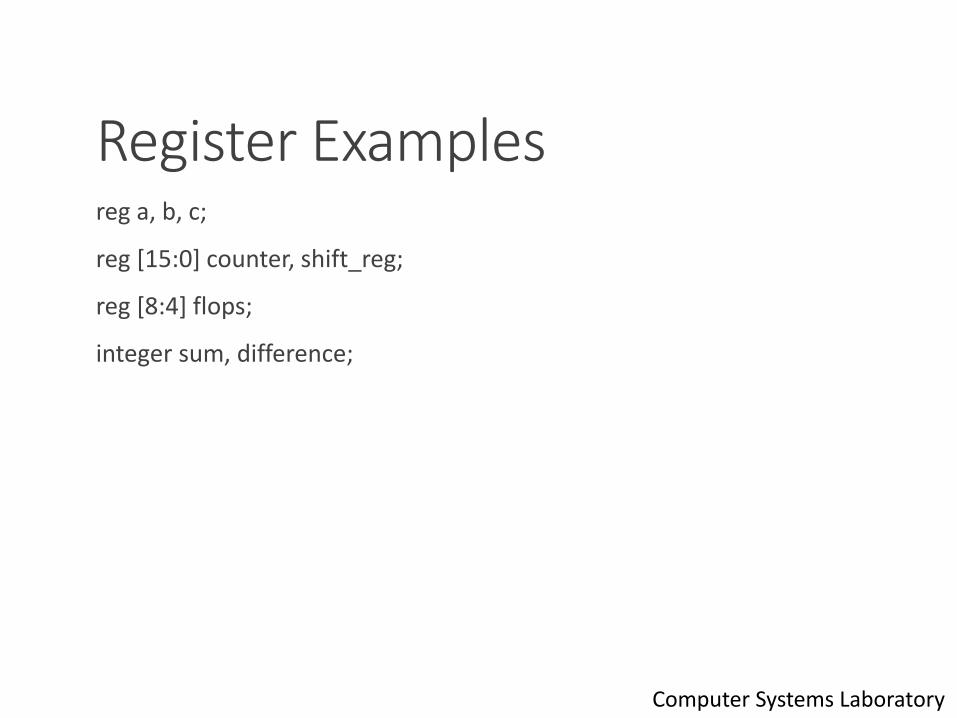
Register Examplesreg a, b, c;
reg [15:0] counter, shift_reg;
reg [8:4] flops;
integer sum, difference;
26Computer Systems Laboratory
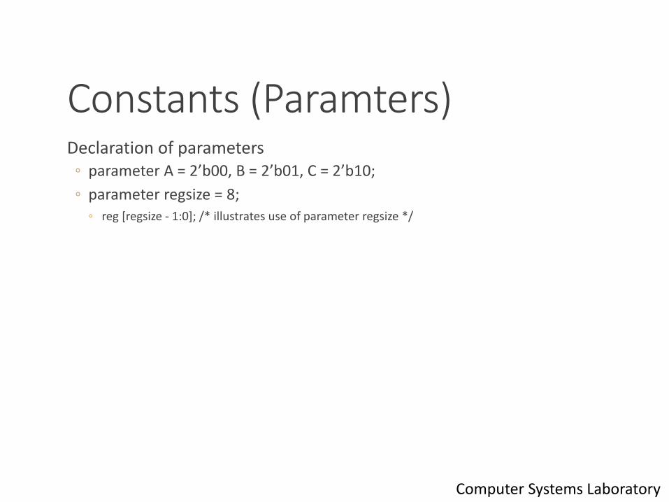
Constants (Paramters)Declaration of parameters
◦ parameter A = 2’b00, B = 2’b01, C = 2’b10;
◦ parameter regsize = 8;◦ reg [regsize - 1:0]; /* illustrates use of parameter regsize */
27Computer Systems Laboratory
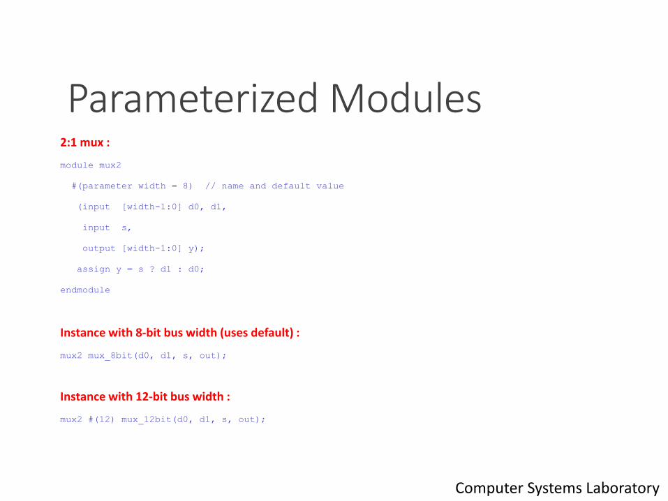
Parameterized Modules2:1 mux :
module mux2
#(parameter width = 8) // name and default value
(input [width-1:0] d0, d1,
input s,
output [width-1:0] y);
assign y = s ? d1 : d0;
endmodule
Instance with 8-bit bus width (uses default) :
mux2 mux_8bit(d0, d1, s, out);
Instance with 12-bit bus width :
mux2 #(12) mux_12bit(d0, d1, s, out);
28Computer Systems Laboratory

OperatorsArithmetic (binary: +, -,*,/,%*); (unary: +, -)
Bitwise (~, &,|,^,~^,^~)
Reduction (&,~&,|,~|,^,~^,^~)
Logical (!,&&,||,==,!=,===,!==)
Relational (<,<=,>,>=)
Shift (>>,<<)
Conditional ? :
Concatenation and Replications {A,B} {4{B}}
* Not supported for variables
29Computer Systems Laboratory
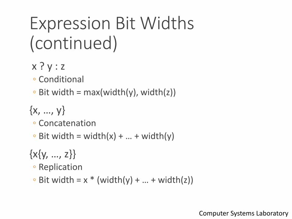
Expression Bit Widths (continued)x ? y : z ◦ Conditional
◦ Bit width = max(width(y), width(z))
{x, …, y}◦ Concatenation
◦ Bit width = width(x) + … + width(y)
{x{y, …, z}} ◦ Replication
◦ Bit width = x * (width(y) + … + width(z))
30Computer Systems Laboratory
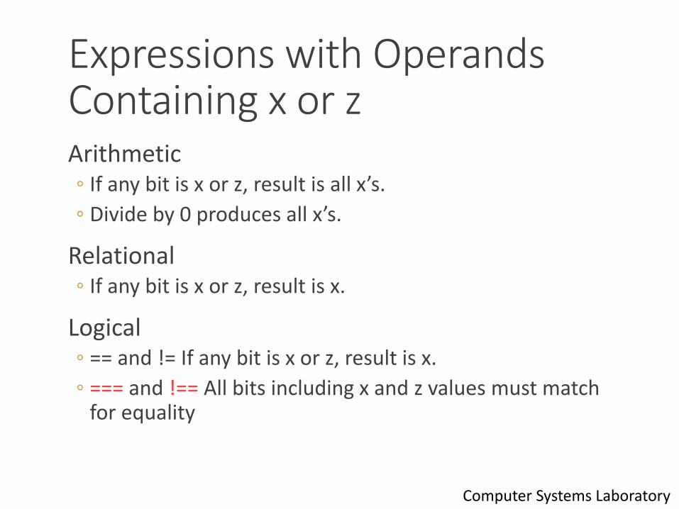
Expressions with Operands Containing x or zArithmetic◦ If any bit is x or z, result is all x’s.
◦ Divide by 0 produces all x’s.
Relational◦ If any bit is x or z, result is x.
Logical◦ == and != If any bit is x or z, result is x.
◦ === and !== All bits including x and z values must match for equality
31Computer Systems Laboratory
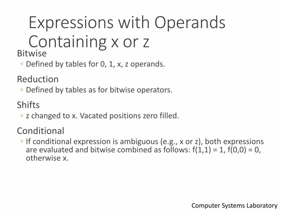
Expressions with Operands Containing x or z
Bitwise◦ Defined by tables for 0, 1, x, z operands.
Reduction◦ Defined by tables as for bitwise operators.
Shifts◦ z changed to x. Vacated positions zero filled.
Conditional◦ If conditional expression is ambiguous (e.g., x or z), both expressions
are evaluated and bitwise combined as follows: f(1,1) = 1, f(0,0) = 0, otherwise x.
32Computer Systems Laboratory
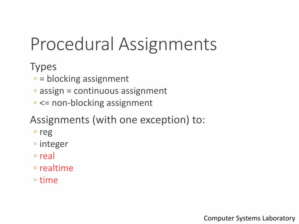
Procedural AssignmentsTypes ◦ = blocking assignment◦ assign = continuous assignment◦ <= non-blocking assignment
Assignments (with one exception) to:◦ reg◦ integer◦ real◦ realtime◦ time
33Computer Systems Laboratory
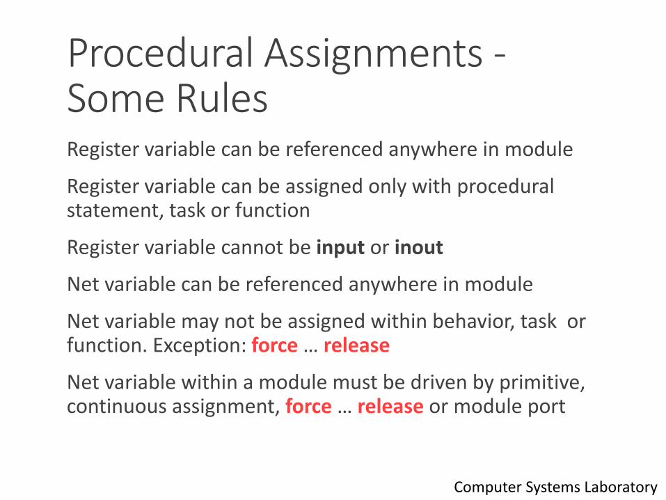
Procedural Assignments -Some RulesRegister variable can be referenced anywhere in module
Register variable can be assigned only with procedural statement, task or function
Register variable cannot be input or inout
Net variable can be referenced anywhere in module
Net variable may not be assigned within behavior, task or function. Exception: force … release
Net variable within a module must be driven by primitive, continuous assignment, force … release or module port
34Computer Systems Laboratory
Procedural Timing, Controls & Synchronization
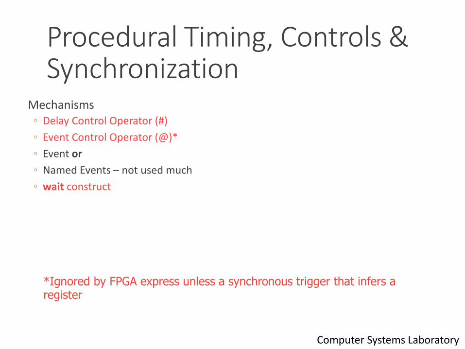
Mechanisms◦ Delay Control Operator (#)
◦ Event Control Operator (@)*
◦ Event or
◦ Named Events – not used much
◦ wait construct
35
*Ignored by FPGA express unless a synchronous trigger that infers a register
Computer Systems Laboratory
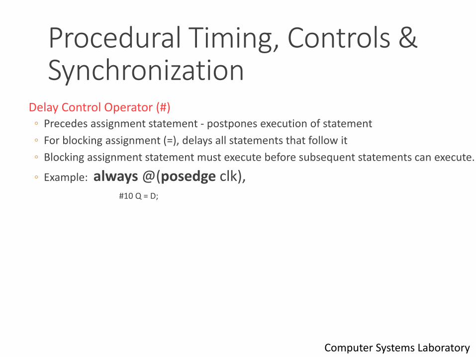
Procedural Timing, Controls & Synchronization
Delay Control Operator (#)◦ Precedes assignment statement - postpones execution of statement
◦ For blocking assignment (=), delays all statements that follow it
◦ Blocking assignment statement must execute before subsequent statements can execute.
◦ Example: always @(posedge clk),#10 Q = D;
36Computer Systems Laboratory
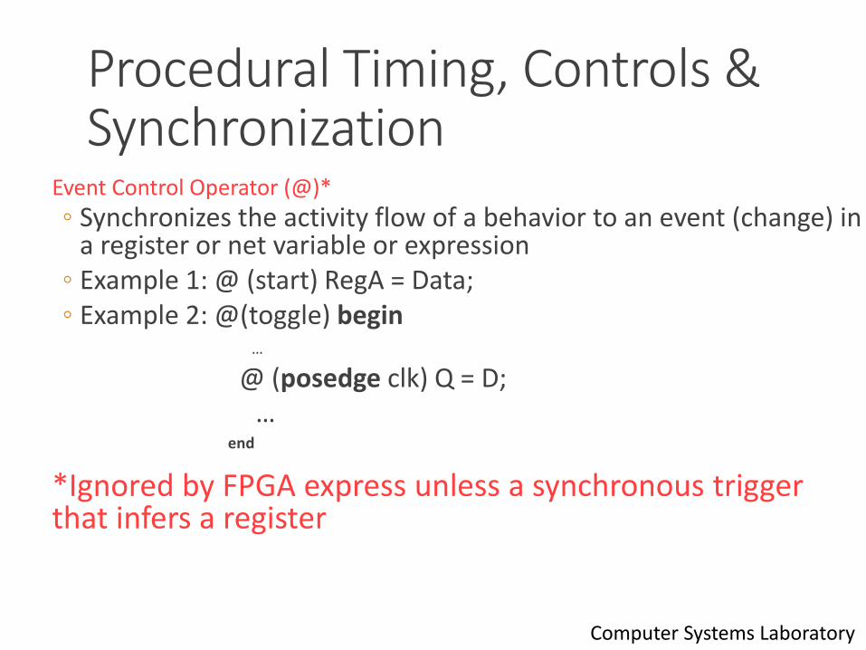
Procedural Timing, Controls & Synchronization
Event Control Operator (@)*
◦ Synchronizes the activity flow of a behavior to an event (change) in a register or net variable or expression
◦ Example 1: @ (start) RegA = Data;◦ Example 2: @(toggle) begin
…
@ (posedge clk) Q = D;…
end
*Ignored by FPGA express unless a synchronous trigger that infers a register
37Computer Systems Laboratory
Procedural Timing, Controls & Synchronization
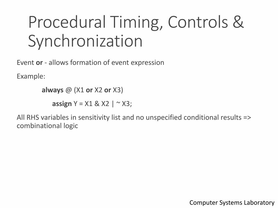
Event or - allows formation of event expression
Example:
always @ (X1 or X2 or X3)
assign Y = X1 & X2 | ~ X3;
All RHS variables in sensitivity list and no unspecified conditional results => combinational logic
38Computer Systems Laboratory
Procedural Timing, Controls & Synchronization
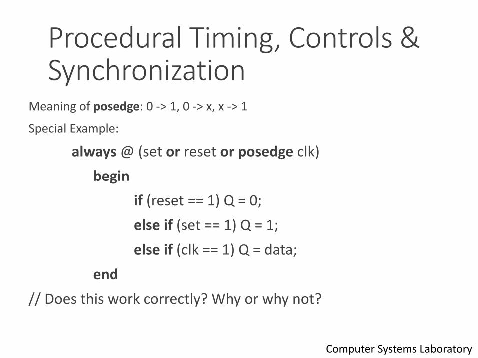
Meaning of posedge: 0 -> 1, 0 -> x, x -> 1
Special Example:
always @ (set or reset or posedge clk)
begin
if (reset == 1) Q = 0;
else if (set == 1) Q = 1;
else if (clk == 1) Q = data;
end
// Does this work correctly? Why or why not?
39Computer Systems Laboratory
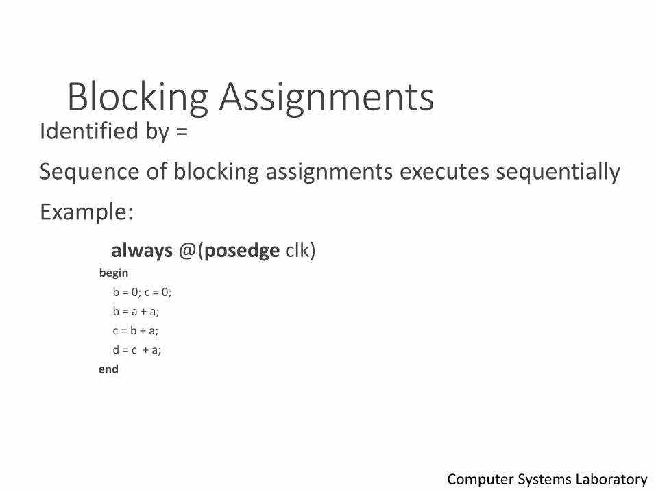
Blocking AssignmentsIdentified by =
Sequence of blocking assignments executes sequentially
Example:
always @(posedge clk)begin
b = 0; c = 0;
b = a + a;
c = b + a;
d = c + a;
end
40Computer Systems Laboratory
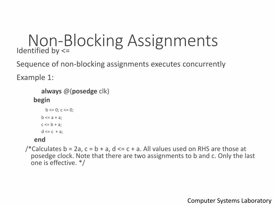
Non-Blocking Assignments Identified by <=
Sequence of non-blocking assignments executes concurrently
Example 1:
always @(posedge clk)begin
b <= 0; c <= 0;
b <= a + a;
c <= b + a;
d <= c + a;
end
/*Calculates b = 2a, c = b + a, d <= c + a. All values used on RHS are those at posedge clock. Note that there are two assignments to b and c. Only the last one is effective. */
41Computer Systems Laboratory

Blocking Assignments - Inter-Assignment Delay
Delays evaluation of RHS and assignment to LHS
Example:
always @(posedge clk)
begin
b = 0; c = 0;
b = a + a; // uses a at posedge clock
#5 c = b + a; // uses a at posedge clock + 5
d = c + a; // uses a at posedge clock + 5
end /*c = 2 a(at posedge clock)+ a(at posedge clock + 5)
d = 2 a(at posedge clock) + 2 a(at posedge clock + 5)*/
42Computer Systems Laboratory
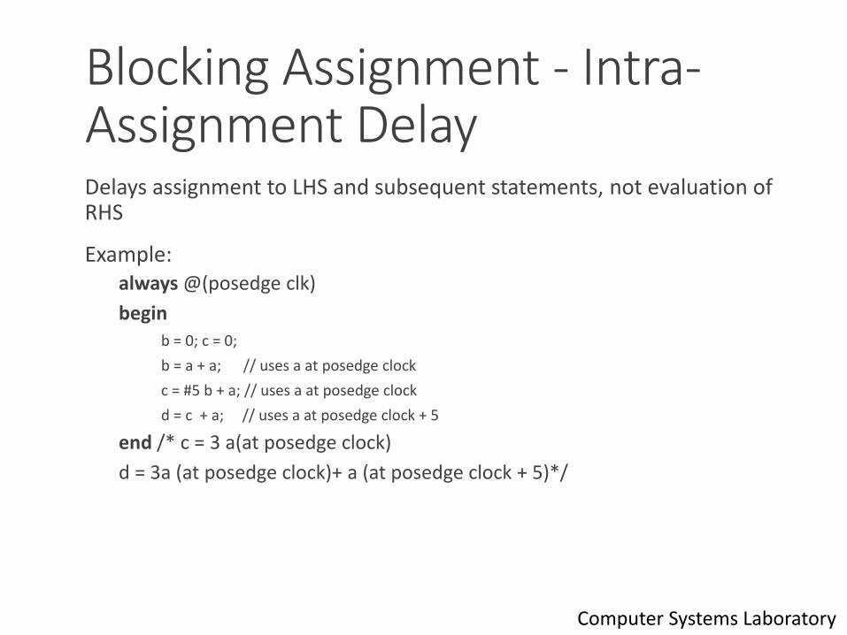
Blocking Assignment - Intra-Assignment DelayDelays assignment to LHS and subsequent statements, not evaluation of RHS
Example:always @(posedge clk)
beginb = 0; c = 0;
b = a + a; // uses a at posedge clock
c = #5 b + a; // uses a at posedge clock
d = c + a; // uses a at posedge clock + 5
end /* c = 3 a(at posedge clock)
d = 3a (at posedge clock)+ a (at posedge clock + 5)*/
43Computer Systems Laboratory
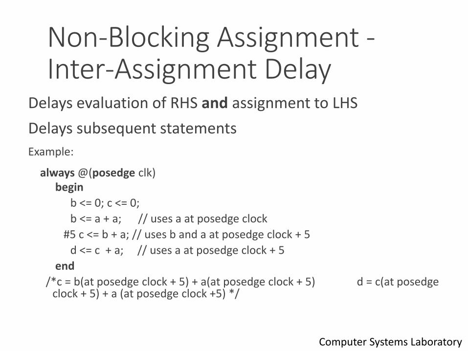
Non-Blocking Assignment -Inter-Assignment Delay
Delays evaluation of RHS and assignment to LHS
Delays subsequent statements
Example:
always @(posedge clk)begin
b <= 0; c <= 0;
b <= a + a; // uses a at posedge clock
#5 c <= b + a; // uses b and a at posedge clock + 5
d <= c + a; // uses a at posedge clock + 5
end
/*c = b(at posedge clock + 5) + a(at posedge clock + 5) d = c(at posedge clock + 5) + a (at posedge clock +5) */
44Computer Systems Laboratory
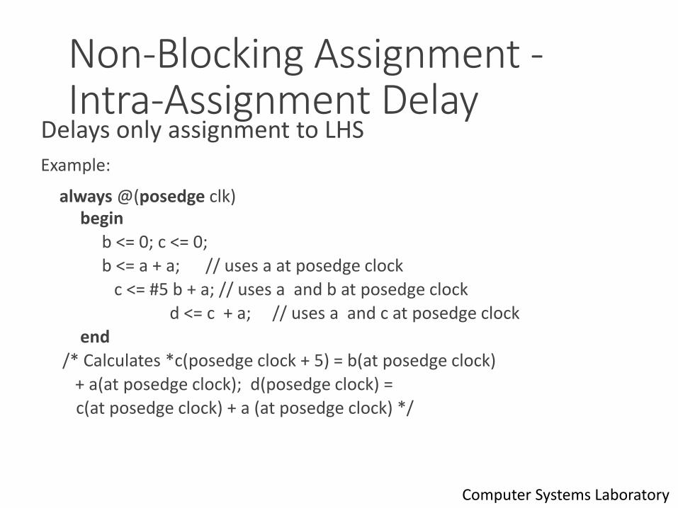
Non-Blocking Assignment -Intra-Assignment Delay
Delays only assignment to LHS
Example:
always @(posedge clk)begin
b <= 0; c <= 0;
b <= a + a; // uses a at posedge clock
c <= #5 b + a; // uses a and b at posedge clock
d <= c + a; // uses a and c at posedge clock
end
/* Calculates *c(posedge clock + 5) = b(at posedge clock)
+ a(at posedge clock); d(posedge clock) =
c(at posedge clock) + a (at posedge clock) */
45Computer Systems Laboratory
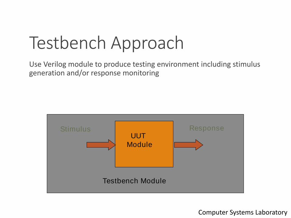
Testbench ApproachUse Verilog module to produce testing environment including stimulus generation and/or response monitoring
46
UUT
Module
Stimulus Response
Testbench Module
Computer Systems Laboratory
Reference MaterialOnline Verilog HDL Quick Reference Guide
◦ http://www.emmelmann.org/Library/Tutorials/docs/verilog_ref_guide/vlog_ref_top.html
◦ Very useful online reference for Verilog-1995. It won’t have the newer Verilog-2001 constructs but it is still a very convenient way to look up 99% of what you need to know
For more information about Verilog Tutorial◦ http://www.sutherland-hdl.com/pdfs/verilog_2001_ref_guide.pdf
◦ http://www.asic-world.com/verilog/index.html
47Computer Systems Laboratory