chap6 micro processors
TRANSCRIPT
8/2/2019 Chap6 Micro Processors
http://slidepdf.com/reader/full/chap6-micro-processors 1/123
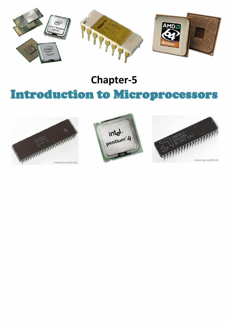
Chapter-5Introduction to Microprocessors
8/2/2019 Chap6 Micro Processors
http://slidepdf.com/reader/full/chap6-micro-processors 2/123

8/2/2019 Chap6 Micro Processors
http://slidepdf.com/reader/full/chap6-micro-processors 3/123
Microprocessor:
• A single chip that contains a whole CPU – Has the ability to fetch and execute instructions
stored in memory
–
Has the ability to access external memory,external I/O and other peripherals
• Examples:
– Intel P4 or AMD Athlon in desktops/notebooks
– ARM processor in Apple iPod
8/2/2019 Chap6 Micro Processors
http://slidepdf.com/reader/full/chap6-micro-processors 4/123
Microprocessor:
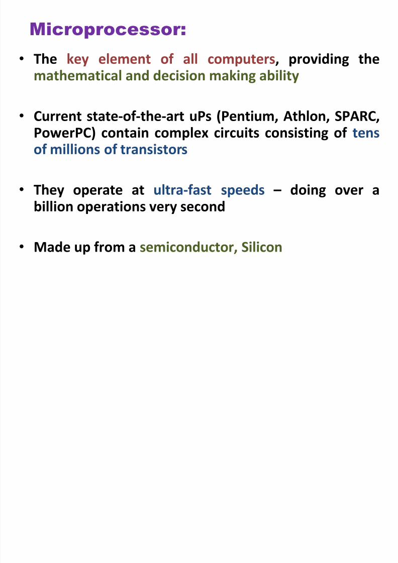
• The key element of all computers, providing themathematical and decision making ability
• Current state-of-the-art uPs (Pentium, Athlon, SPARC,
PowerPC) contain complex circuits consisting of tensof millions of transistors
• They operate at ultra-fast speeds – doing over a
billion operations very second
• Made up from a semiconductor, Silicon

8/2/2019 Chap6 Micro Processors
http://slidepdf.com/reader/full/chap6-micro-processors 5/123
Microprocessor Generations:
• First generation: 1971-78
– Behind the power curve(16-bit, <50k transistors)
• Second Generation: 1979-85 – Becoming “real” computers
(32-bit , >50k transistors)• Third Generation: 1985-89
– Challenging the “establishment”(Reduced Instruction Set Computer/RISC,>100k transistors)
• Fourth Generation: 1990- – Architectural and performance leadership
(64-bit, > 1M transistors,Intel/AMD translate into RISC internally)
8/2/2019 Chap6 Micro Processors
http://slidepdf.com/reader/full/chap6-micro-processors 6/123
8/2/2019 Chap6 Micro Processors
http://slidepdf.com/reader/full/chap6-micro-processors 7/123
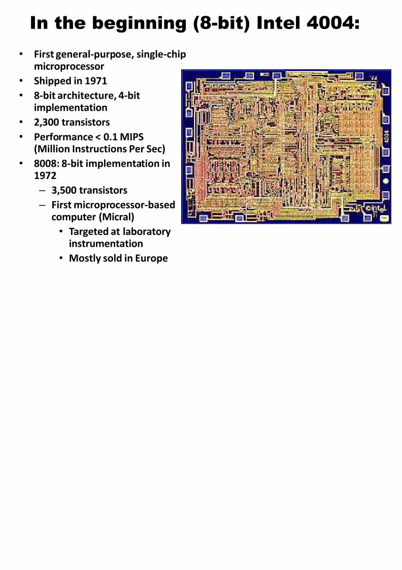
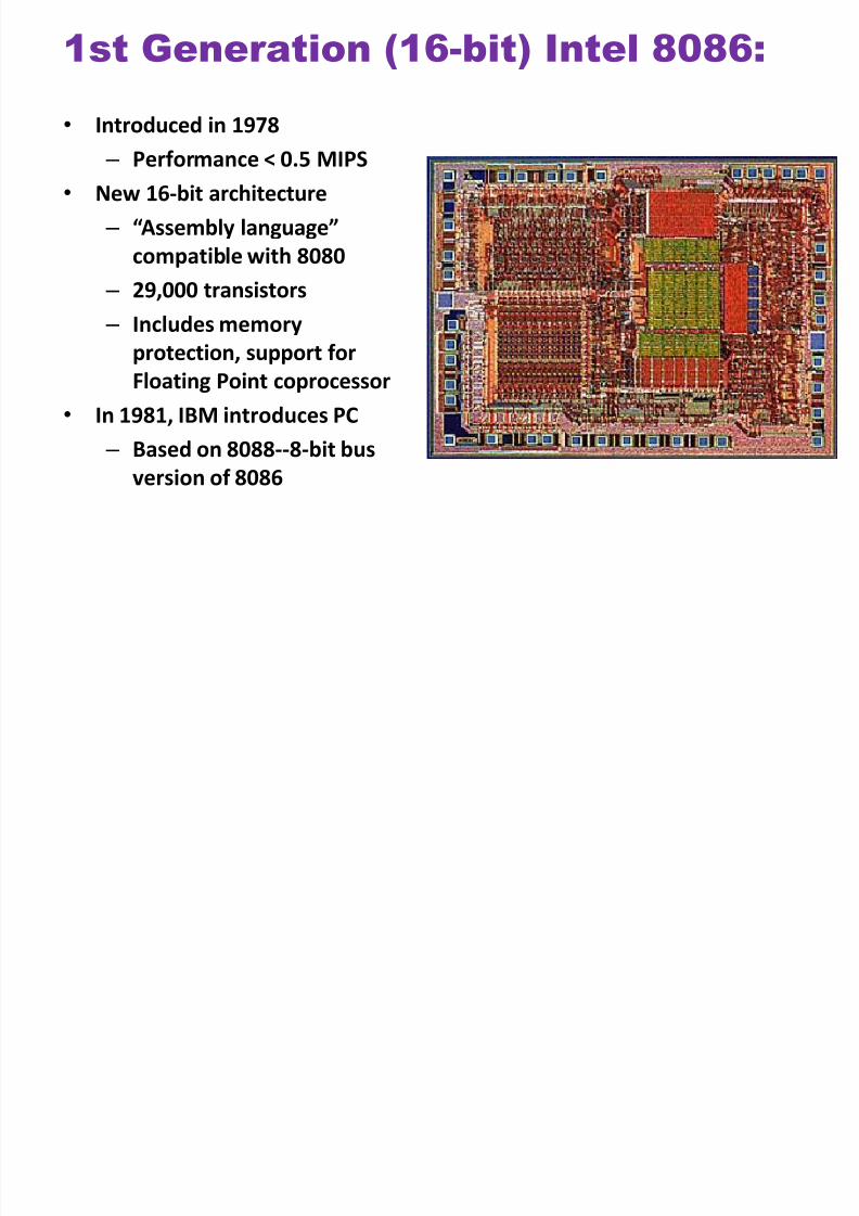
1st Generation (16-bit) Intel 8086:
• Introduced in 1978
– Performance < 0.5 MIPS
• New 16-bit architecture
– “Assembly language”
compatible with 8080
–
29,000 transistors – Includes memory
protection, support for
Floating Point coprocessor
• In 1981, IBM introduces PC
– Based on 8088--8-bit busversion of 8086
8/2/2019 Chap6 Micro Processors
http://slidepdf.com/reader/full/chap6-micro-processors 8/123
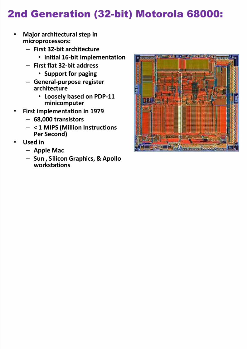
2nd Generation (32-bit) Motorola 68000:
• Major architectural step in
microprocessors: – First 32-bit architecture
• initial 16-bit implementation
– First flat 32-bit address
• Support for paging
– General-purpose registerarchitecture
• Loosely based on PDP-11minicomputer
• First implementation in 1979
– 68,000 transistors
–
< 1 MIPS (Million InstructionsPer Second)
• Used in
– Apple Mac
– Sun , Silicon Graphics, & Apolloworkstations
8/2/2019 Chap6 Micro Processors
http://slidepdf.com/reader/full/chap6-micro-processors 9/123
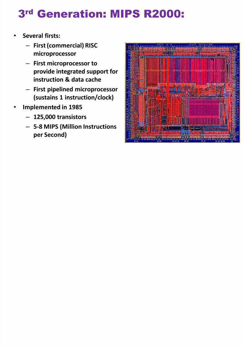
3rd Generation: MIPS R2000:
• Several firsts:
– First (commercial) RISC
microprocessor
– First microprocessor to
provide integrated support for
instruction & data cache
– First pipelined microprocessor
(sustains 1 instruction/clock)
• Implemented in 1985
– 125,000 transistors
–
5-8 MIPS (Million Instructionsper Second)
8/2/2019 Chap6 Micro Processors
http://slidepdf.com/reader/full/chap6-micro-processors 10/123
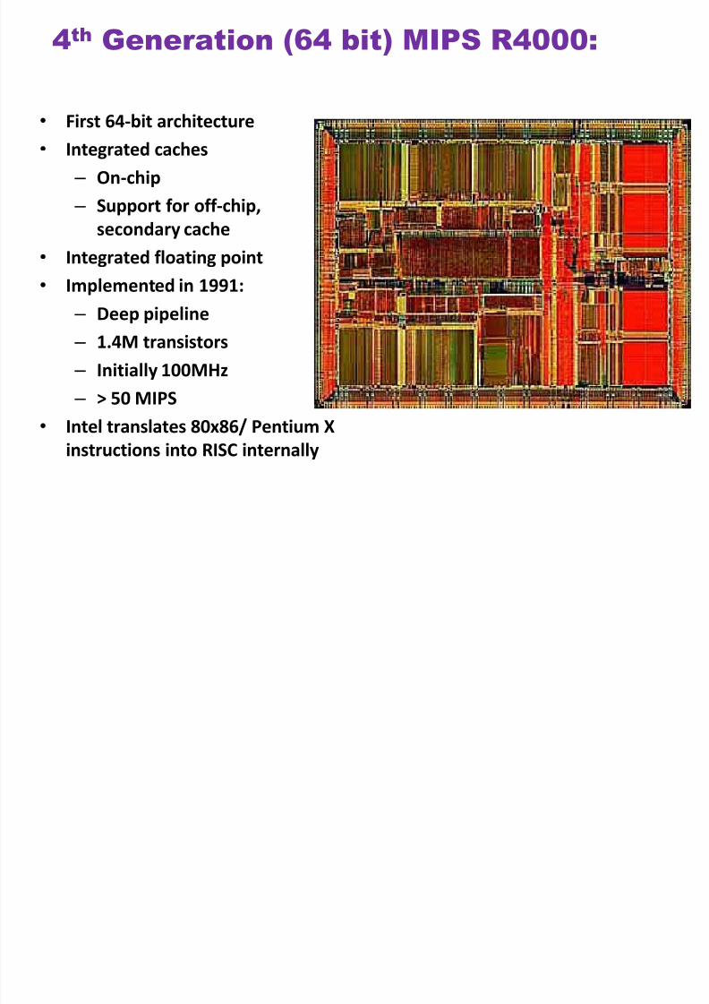
4th Generation (64 bit) MIPS R4000:
•First 64-bit architecture
• Integrated caches
– On-chip
– Support for off-chip,
secondary cache
• Integrated floating point
• Implemented in 1991:
– Deep pipeline
– 1.4M transistors
–Initially 100MHz
– > 50 MIPS
• Intel translates 80x86/ Pentium X
instructions into RISC internally
8/2/2019 Chap6 Micro Processors
http://slidepdf.com/reader/full/chap6-micro-processors 11/123
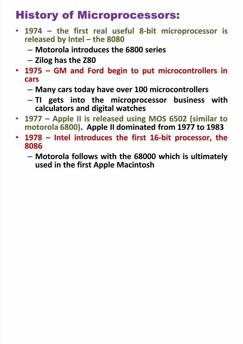
History of Microprocessors:
• 1974 – the first real useful 8-bit microprocessor is
released by Intel – the 8080 – Motorola introduces the 6800 series
– Zilog has the Z80
• 1975 – GM and Ford begin to put microcontrollers incars
– Many cars today have over 100 microcontrollers
– TI gets into the microprocessor business withcalculators and digital watches
• 1977 – Apple II is released using MOS 6502 (similar to
motorola 6800). Apple II dominated from 1977 to 1983• 1978 – Intel introduces the first 16-bit processor, the
8086
– Motorola follows with the 68000 which is ultimatelyused in the first Apple Macintosh
8/2/2019 Chap6 Micro Processors
http://slidepdf.com/reader/full/chap6-micro-processors 12/123
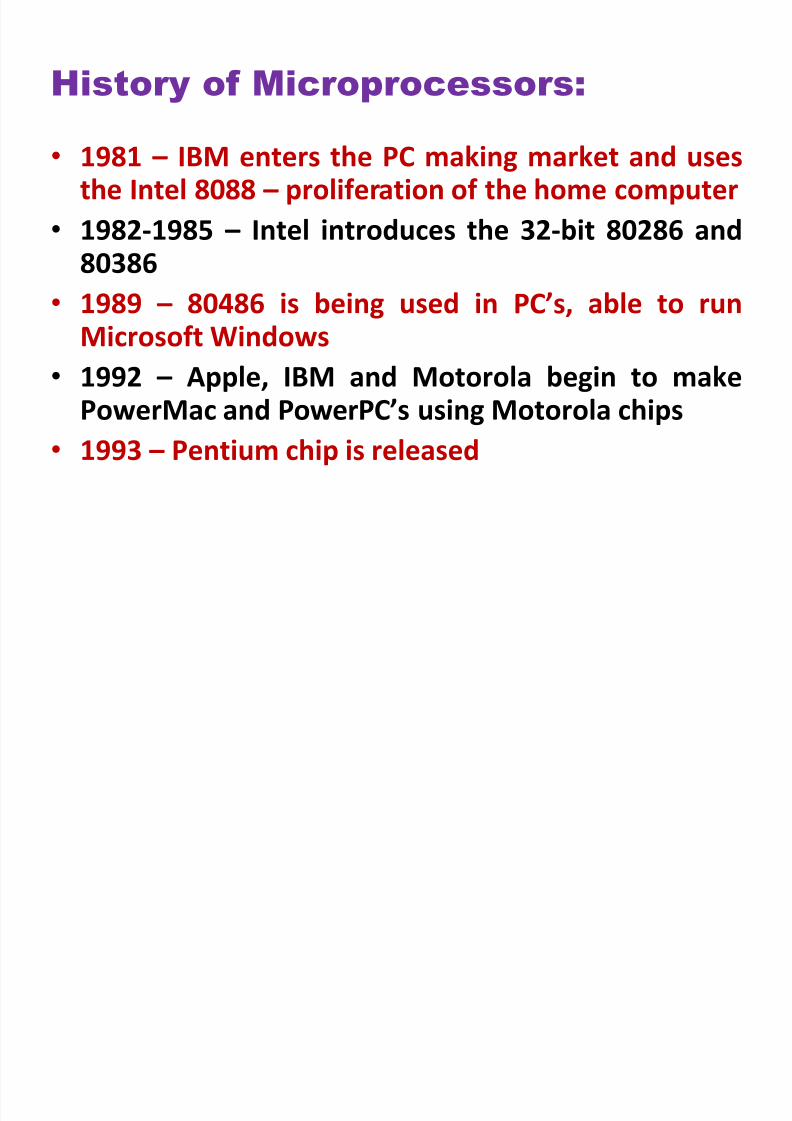
History of Microprocessors:
• 1981 – IBM enters the PC making market and usesthe Intel 8088 – proliferation of the home computer
• 1982-1985 – Intel introduces the 32-bit 80286 and
80386• 1989 – 80486 is being used in PC’s, able to run
Microsoft Windows
• 1992 – Apple, IBM and Motorola begin to make
PowerMac and PowerPC’s using Motorola chips• 1993 – Pentium chip is released
8/2/2019 Chap6 Micro Processors
http://slidepdf.com/reader/full/chap6-micro-processors 13/123
8/2/2019 Chap6 Micro Processors
http://slidepdf.com/reader/full/chap6-micro-processors 14/123
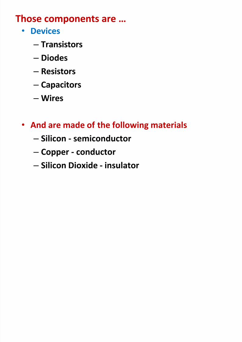
Those components are … • Devices
– Transistors
– Diodes
– Resistors
– Capacitors – Wires
•
And are made of the following materials – Silicon - semiconductor
– Copper - conductor
–
Silicon Dioxide - insulator
8/2/2019 Chap6 Micro Processors
http://slidepdf.com/reader/full/chap6-micro-processors 15/123
8/2/2019 Chap6 Micro Processors
http://slidepdf.com/reader/full/chap6-micro-processors 16/123
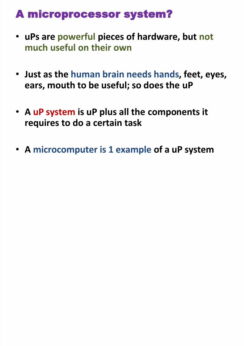
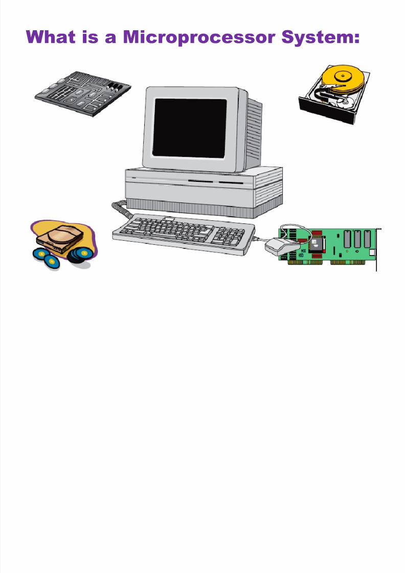
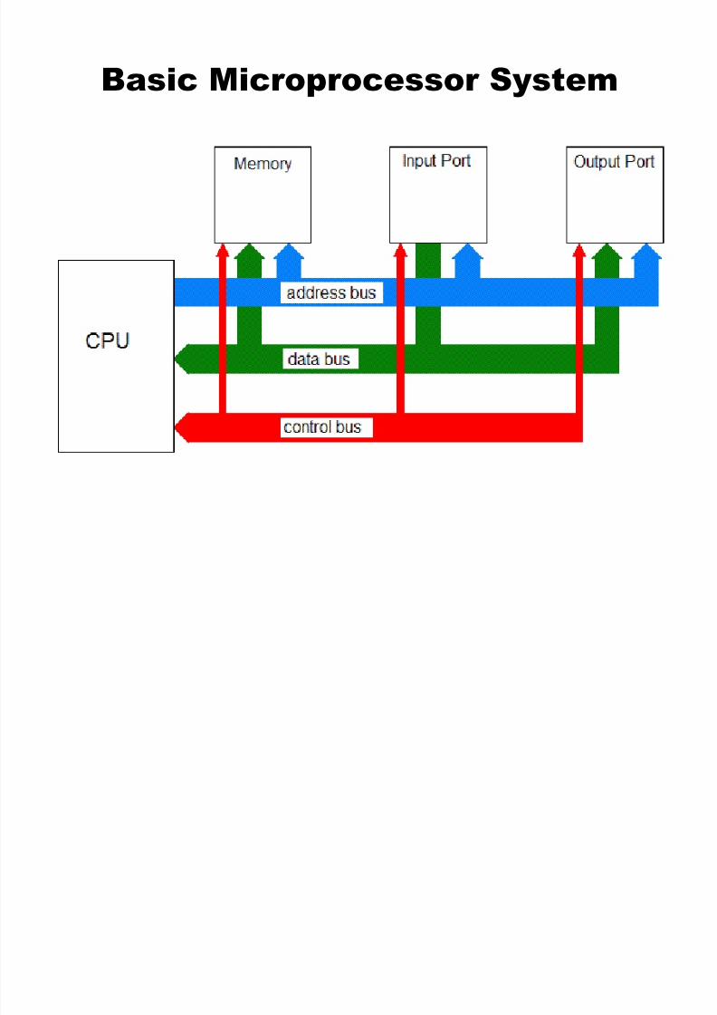
What is a Microprocessor System:

8/2/2019 Chap6 Micro Processors
http://slidepdf.com/reader/full/chap6-micro-processors 17/123
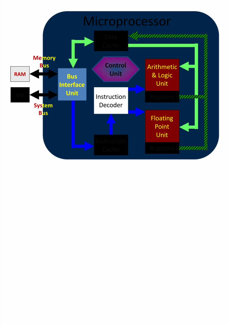
uP Building Blocks
8/2/2019 Chap6 Micro Processors
http://slidepdf.com/reader/full/chap6-micro-processors 18/123
Registers
Registers
Microprocessor
Instruction
Cache
Arithmetic
& Logic
Unit
Control
UnitBus
Interface
Unit
Data
Cache
Instruction
Decoder
I/O
RAM
Memory
Bus
System
Bus
FloatingPoint
Unit
8/2/2019 Chap6 Micro Processors
http://slidepdf.com/reader/full/chap6-micro-processors 19/123
8/2/2019 Chap6 Micro Processors
http://slidepdf.com/reader/full/chap6-micro-processors 20/123
8/2/2019 Chap6 Micro Processors
http://slidepdf.com/reader/full/chap6-micro-processors 21/123
Bus Interface Unit:
• Receives instructions & data from main memory
• Instructions are then sent to the instruction cache,
data to the data cache
• Also receives the processed data and sends it to themain memory
8/2/2019 Chap6 Micro Processors
http://slidepdf.com/reader/full/chap6-micro-processors 22/123
Computer Buses:
•
Address bus: carries the address of a uniquememory or input/output (I/O) device
• Data bus: carries data stored in memory (or an I/O
device) to the CPU or from the CPU to the memory(or I/O device)
•Control bus: is a collection of control signals thatcoordinate and synchronize the whole system
8/2/2019 Chap6 Micro Processors
http://slidepdf.com/reader/full/chap6-micro-processors 23/123
• The MPU communicates with Memory and
I/O using the System Bus: – Address bus
• Unidirectional
•
Memory and I/O Addresses – Data bus
• Bidirectional
• Transfers Binary Data and Instructions
– Control bus
• Read and Write timing signals
8/2/2019 Chap6 Micro Processors
http://slidepdf.com/reader/full/chap6-micro-processors 24/123
Instruction Decoder:
• This unit receives the programming instructions and
decodes them into a form that is understandable by
the processing units, i.e. the ALU or FPU
• Then, it passes on the decoded instruction to the
ALU or FPU
8/2/2019 Chap6 Micro Processors
http://slidepdf.com/reader/full/chap6-micro-processors 25/123
Arithmetic & Logic Unit (ALU):
• Also known as the “Integer Unit”
• It performs whole-number math calculations(subtract, multiply, divide, etc) comparisons (isgreater than, is smaller than, etc.) and logicaloperations (NOT, OR, AND, etc)
•
The new breed of popular uPs have not one but twoalmost identical ALU’s that can do calculationssimultaneously, doubling the capability
8/2/2019 Chap6 Micro Processors
http://slidepdf.com/reader/full/chap6-micro-processors 26/123
Floating-Point Unit (FPU):
• Also known as the “Numeric Unit”
• It performs calculations that involve numbers represented inthe scientific notation (also known as floating-pointnumbers).
• This notation can represent extremely small and extremelylarge numbers in a compact form
• Floating-point calculations are required for doing graphics,
engineering and scientific work
• The ALU can do these calculations as well, but will do themvery slowly
8/2/2019 Chap6 Micro Processors
http://slidepdf.com/reader/full/chap6-micro-processors 27/123
Registers:
• Both ALU & FPU have a very small amount of super-
fast private memory placed right next to them for
their exclusive use. These are called registers
• The ALU & FPU store intermediate and final results
from their calculations in these registers
• Processed data goes back to the data cache and
then to main memory from these registers
8/2/2019 Chap6 Micro Processors
http://slidepdf.com/reader/full/chap6-micro-processors 28/123
Control Unit:
• The brain of the uP
• Manages the whole uP
• Tasks include fetching instructions & data,
storing data, managing input/output
devices
8/2/2019 Chap6 Micro Processors
http://slidepdf.com/reader/full/chap6-micro-processors 29/123
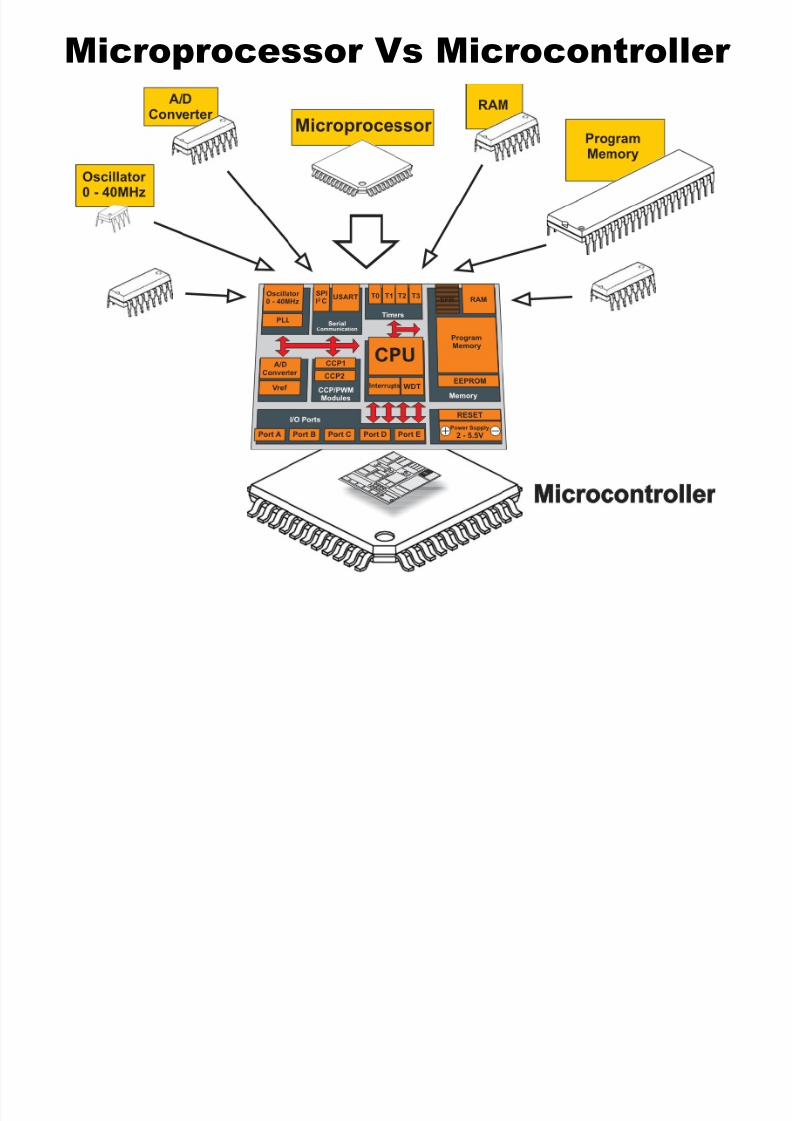
Microcontroller:
• Microcontroller is a single chip micro computermade through VLSI fabrication.
• A microcontroller also called an embedded
controller because the microcontroller and its
support circuits are often built into, or embedded
in, the devices they control.
• A microcontroller is available in different word
lengths.(4bit,8bit,16bit,32bit,64bit and 128 bit)
8/2/2019 Chap6 Micro Processors
http://slidepdf.com/reader/full/chap6-micro-processors 30/123
• Any device that measures, stores, controls, calculates,or displays information must have a microcontrollerchip inside.
• The largest single use for microcontrollers is inautomobile industry (microcontrollers widely used forcontrolling engines and power controls inautomobiles).
•
You can also find microcontrollers inside keyboards,mouse, modems, printers, and other peripherals.
• In test equipments, microcontrollers make it easy toadd features such as the ability to storemeasurements, to create and store user routines, and
to display messages and waveforms.• Consumer products that use microcontrollers include
digital camcorders, optical players, LCD/LED displayunits, etc.
8/2/2019 Chap6 Micro Processors
http://slidepdf.com/reader/full/chap6-micro-processors 31/123
8/2/2019 Chap6 Micro Processors
http://slidepdf.com/reader/full/chap6-micro-processors 32/123
8/2/2019 Chap6 Micro Processors
http://slidepdf.com/reader/full/chap6-micro-processors 33/123
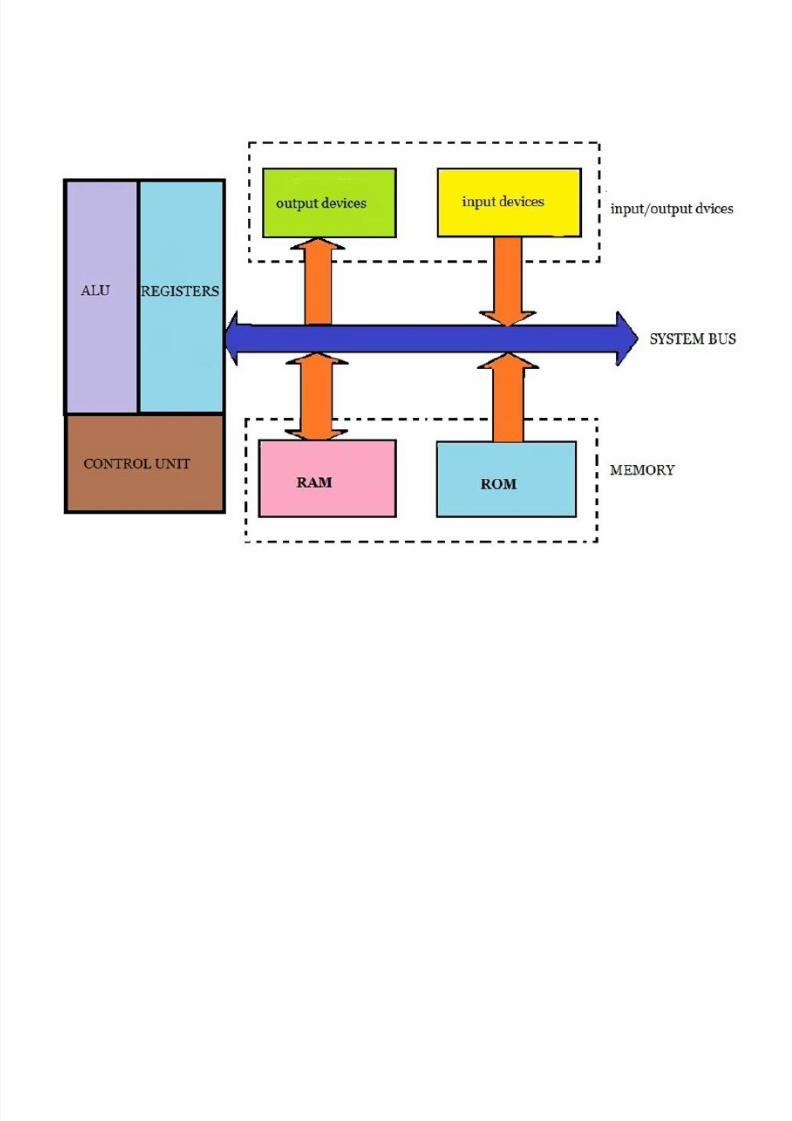
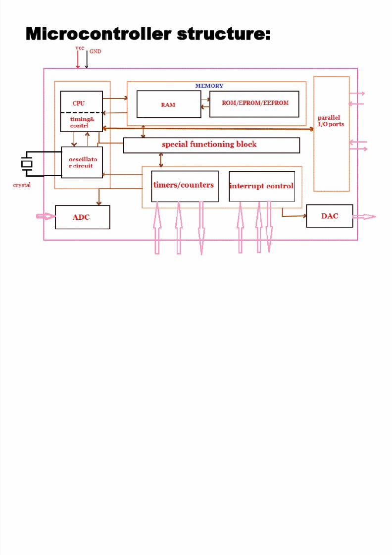
Microcontroller structure:
8/2/2019 Chap6 Micro Processors
http://slidepdf.com/reader/full/chap6-micro-processors 34/123
CPU: • CPU is the brain of a microcontroller .
•CPU is responsible for fetching the instruction, decodesit, then finally executed. CPU connects every part of amicrocontroller into a single system.
• The primary function of CPU is fetching and decodinginstructions.
• Instruction fetched from program memory must bedecoded by the CPU.
Memory:
• The function of memory in a microcontroller is same as
microprocessor. It is used to store data and program.• A microcontroller usually has a certain amount of RAM
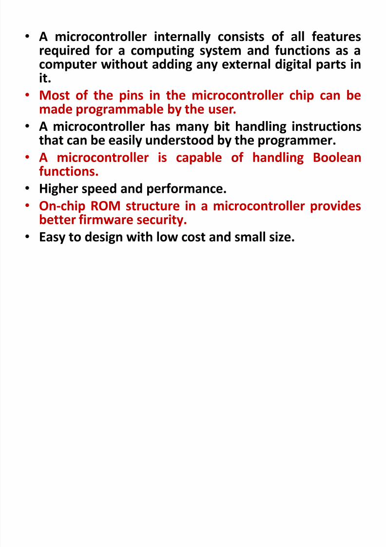
and ROM (EEPROM, EPROM, etc) or flash memories forstoring program source codes.

8/2/2019 Chap6 Micro Processors
http://slidepdf.com/reader/full/chap6-micro-processors 35/123
Parallel input/output ports: • Parallel input/output ports are mainly used to
drive/interface various devices such as LCD’S, LED’S,
printers, memories, etc to a microcontroller.Serial ports: • Serial ports provide various serial interfaces between
microcontroller and other peripherals like parallel ports.
Timers/counters: • This is the one of the useful function of a microcontroller.
• A microcontroller may have more than one timer andcounters.
• The timers and counters provide all timing and counting
functions inside the microcontroller.• The major operations of this section are perform clock
functions, modulations, pulse generations, frequencymeasuring, making oscillations, etc. This also can be usedfor counting external pulses.
8/2/2019 Chap6 Micro Processors
http://slidepdf.com/reader/full/chap6-micro-processors 36/123
Analog to Digital Converter (ADC):
• ADC converters are used for converting the analog
signal to digital form.• The input signal in this converter should be in analog
form (e.g. sensor output) and the output from thisunit is in digital form.
• The digital output can be use for various digitalapplications (e.g. measurement devices).
Digital to Analog Converter (DAC): • DAC perform reversal operation of ADC conversion.
• DAC convert the digital signal into analog format. Itusually used for controlling analog devices like DCmotors, various drives, etc.

8/2/2019 Chap6 Micro Processors
http://slidepdf.com/reader/full/chap6-micro-processors 37/123
Interrupt control: • The interrupt control used for providing interrupt
(delay) for a working program.• The interrupt may be external (activated by using
interrupt pin) or internal (by using interruptinstruction during programming).
Special functioning block:
• Some microcontrollers used only for some specialapplications (e.g. space systems and robotics)these controllers containing additional ports toperform such special operations.
• This considered as special functioning block.
8/2/2019 Chap6 Micro Processors
http://slidepdf.com/reader/full/chap6-micro-processors 38/123
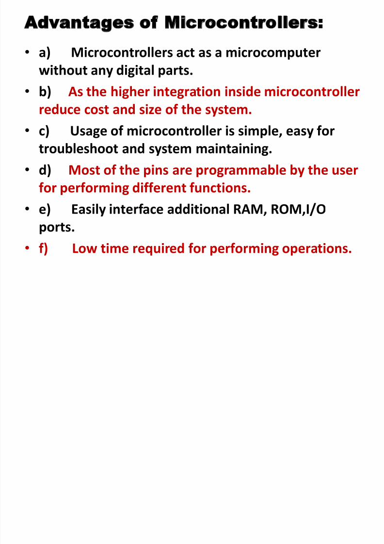
Advantages of Microcontrollers:
• a) Microcontrollers act as a microcomputer
without any digital parts.• b) As the higher integration inside microcontroller
reduce cost and size of the system.
•
c) Usage of microcontroller is simple, easy fortroubleshoot and system maintaining.
• d) Most of the pins are programmable by the user
for performing different functions.
• e) Easily interface additional RAM, ROM,I/O
ports.
• f) Low time required for performing operations.
8/2/2019 Chap6 Micro Processors
http://slidepdf.com/reader/full/chap6-micro-processors 39/123
8/2/2019 Chap6 Micro Processors
http://slidepdf.com/reader/full/chap6-micro-processors 40/123
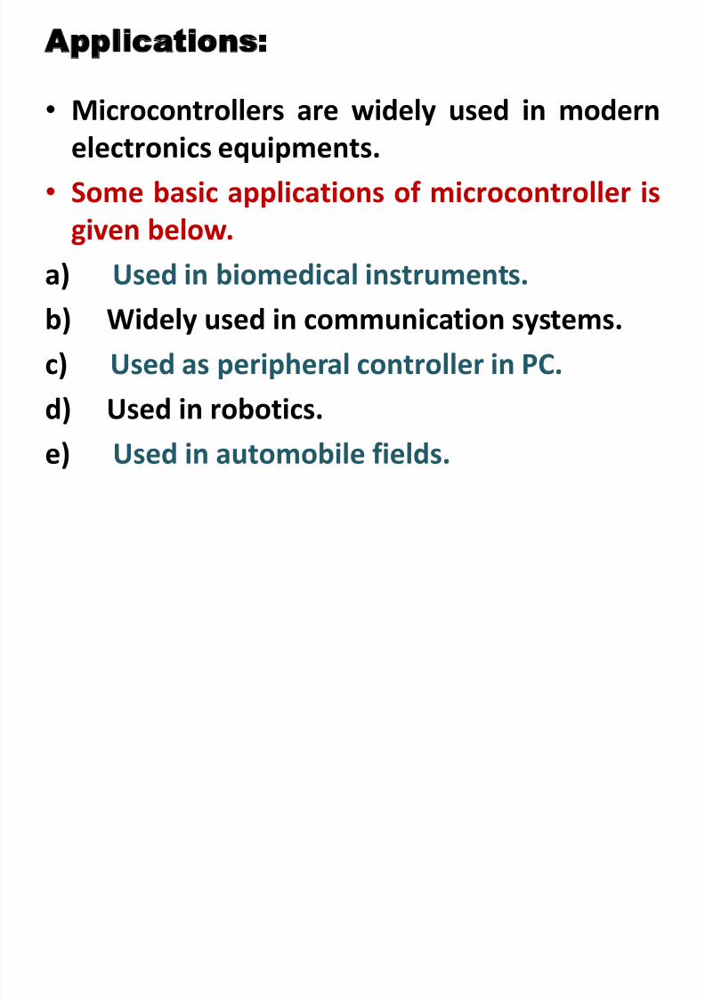
Applications:
• Microcontrollers are widely used in modern
electronics equipments.
• Some basic applications of microcontroller is
given below.
a) Used in biomedical instruments.
b) Widely used in communication systems.
c) Used as peripheral controller in PC.d) Used in robotics.
e) Used in automobile fields.
8/2/2019 Chap6 Micro Processors
http://slidepdf.com/reader/full/chap6-micro-processors 41/123
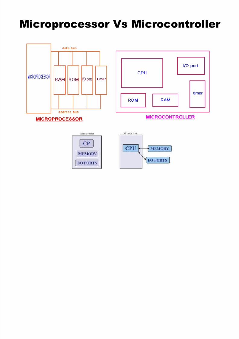
Microprocessor Vs Microcontroller
8/2/2019 Chap6 Micro Processors
http://slidepdf.com/reader/full/chap6-micro-processors 42/123
Microprocessor Vs Microcontroller
8/2/2019 Chap6 Micro Processors
http://slidepdf.com/reader/full/chap6-micro-processors 43/123
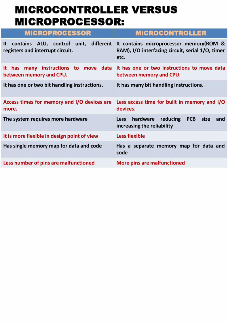
MICROCONTROLLER VERSUS
MICROPROCESSOR: MICROPROCESSOR MICROCONTROLLER
It contains ALU, control unit, differentregisters and interrupt circuit.
It contains microprocessor memory(ROM &RAM), I/O interfacing circuit, serial 1/O, timer
etc.
It has many instructions to move data
between memory and CPU.
It has one or two instructions to move data
between memory and CPU.
It has one or two bit handling instructions. It has many bit handling instructions.
Access times for memory and I/O devices are
more.
Less access time for built in memory and I/O
devices.
The system requires more hardware Less hardware reducing PCB size andincreasing the reliability
It is more flexible in design point of view Less flexible
Has single memory map for data and code Has a separate memory map for data and
code
Less number of pins are malfunctioned More pins are malfunctioned
8/2/2019 Chap6 Micro Processors
http://slidepdf.com/reader/full/chap6-micro-processors 44/123
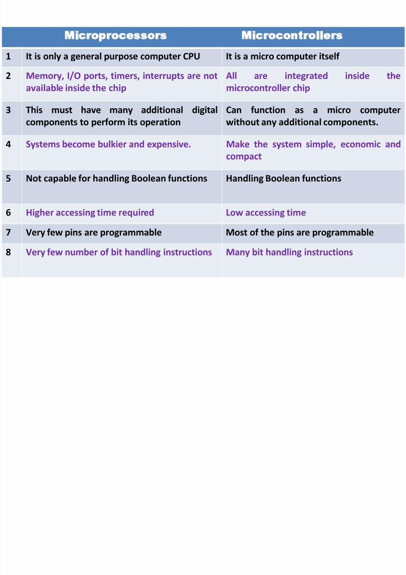
Microprocessors Microcontrollers
1 It is only a general purpose computer CPU It is a micro computer itself
2 Memory, I/O ports, timers, interrupts are notavailable inside the chip
All are integrated inside themicrocontroller chip
3 This must have many additional digital
components to perform its operation
Can function as a micro computer
without any additional components.
4 Systems become bulkier and expensive. Make the system simple, economic andcompact
5 Not capable for handling Boolean functions Handling Boolean functions
6 Higher accessing time required Low accessing time
7 Very few pins are programmable Most of the pins are programmable
8 Very few number of bit handling instructions Many bit handling instructions
8/2/2019 Chap6 Micro Processors
http://slidepdf.com/reader/full/chap6-micro-processors 45/123
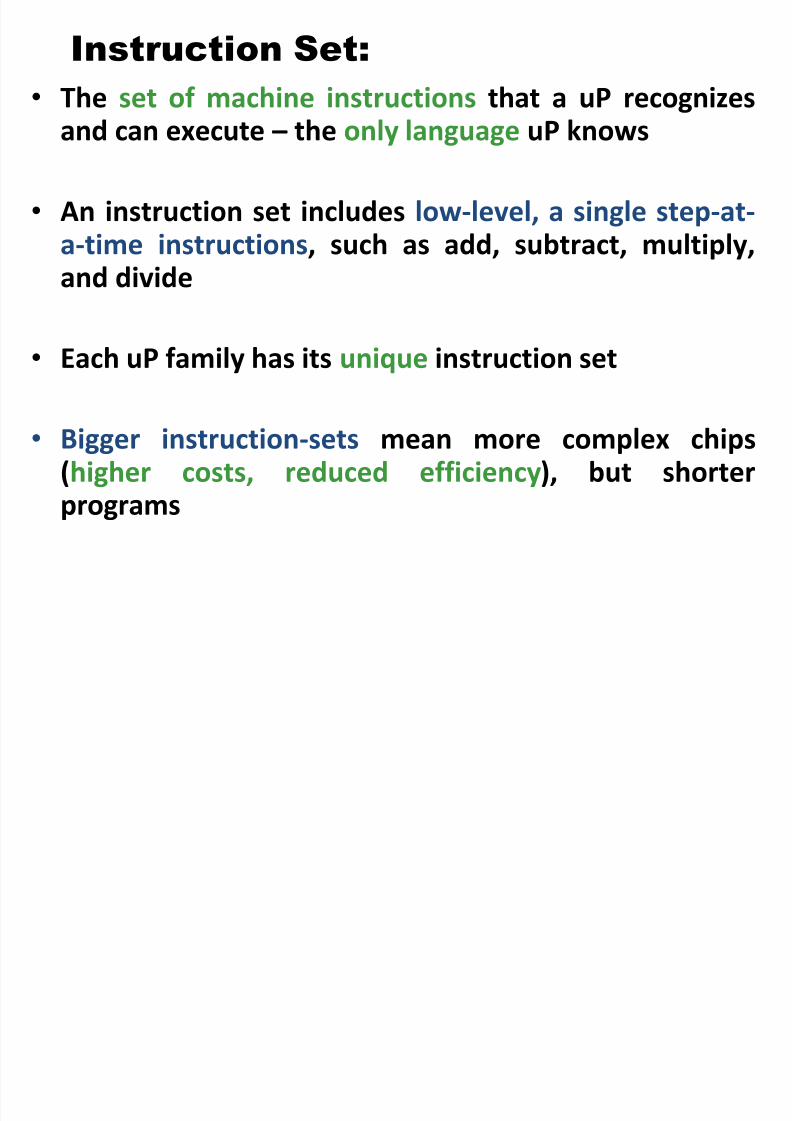
Instruction Set:
• The set of machine instructions that a uP recognizes
and can execute – the only language uP knows
• An instruction set includes low-level, a single step-at-a-time instructions, such as add, subtract, multiply,
and divide
• Each uP family has its unique instruction set
• Bigger instruction-sets mean more complex chips(higher costs, reduced efficiency), but shorterprograms
8/2/2019 Chap6 Micro Processors
http://slidepdf.com/reader/full/chap6-micro-processors 46/123
• An instruction generally specifies:
a. The task to be carried out.
b. The addresses in the memory where the operands
are available.
c. The address in the memory where result has to be
stored.
d. The address in the memory where next instruction
an be found.
8/2/2019 Chap6 Micro Processors
http://slidepdf.com/reader/full/chap6-micro-processors 47/123
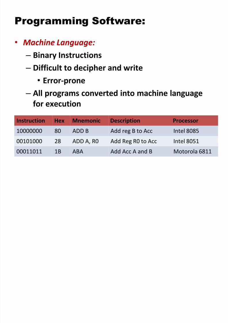
Programming Software:
• Machine Language: – Binary Instructions
– Difficult to decipher and write
•Error-prone
– All programs converted into machine language
for execution
Instruction Hex Mnemonic Description Processor10000000 80 ADD B Add reg B to Acc Intel 8085
00101000 28 ADD A, R0 Add Reg R0 to Acc Intel 8051
00011011 1B ABA Add Acc A and B Motorola 6811
8/2/2019 Chap6 Micro Processors
http://slidepdf.com/reader/full/chap6-micro-processors 48/123
8/2/2019 Chap6 Micro Processors
http://slidepdf.com/reader/full/chap6-micro-processors 49/123
•
It is difficult to write program in sets of 0 and 1.
• Manufacturers have devised English-like language
words to represent binary instruction.
• Programmers can write programs called assembly
language programs.

8/2/2019 Chap6 Micro Processors
http://slidepdf.com/reader/full/chap6-micro-processors 50/123
• Assembly Language:
– Machine instructions represented in
mnemonics
– One-to-one correspondence
– Efficient execution and use of memory
– Machine-specific

8/2/2019 Chap6 Micro Processors
http://slidepdf.com/reader/full/chap6-micro-processors 51/123
8/2/2019 Chap6 Micro Processors
http://slidepdf.com/reader/full/chap6-micro-processors 52/123
• High-Level Languages:
– BASIC, C, and C++
–
Written in statements of spoken languages – Machine independent
– Easy to write and troubleshoot
– Larger memory and less efficient execution

8/2/2019 Chap6 Micro Processors
http://slidepdf.com/reader/full/chap6-micro-processors 53/123
Complex Instruction set
computer (CISC):
• In the 1970’s & 80’s memory was both slow andexpensive.
• High cost and poor performance facilitated the
need for compact and efficient code.Code written in a high level language took muchlonger to translate into assembler, which lead tobloated code and slower program execution.
• bigger program->more storage->more money• Hence needed to reduce the number of instructions
per program
8/2/2019 Chap6 Micro Processors
http://slidepdf.com/reader/full/chap6-micro-processors 54/123
Complex Instruction set computer
(CISC):
• Number of instructions are reduced by havingmultiple operations within a single instruction
• Multiple operations lead to many different kinds of
instructions that access memory
• In turn making instruction length variable and fetch-
decode execute time unpredictable – making it
more complex
• The CISC philosophy was to shift some of theprogramming burden to the hardware level.
• Thus hardware handles the complexity
8/2/2019 Chap6 Micro Processors
http://slidepdf.com/reader/full/chap6-micro-processors 55/123
Complex Instruction set computer
(CISC):
Features:
Large No. of instructions.
Single instruction will perform a complex operation.
Number of instructions per program is minimised.
Execution time for each instruction is different.
Execution time for an instruction may take several clock
cycles.
Efficient use of memory space.
Works faster for complex instructions but may be slow forsimple tasks.
Emphasis on complex hardware to store a large
instruction set
8/2/2019 Chap6 Micro Processors
http://slidepdf.com/reader/full/chap6-micro-processors 56/123
Most common examples of CISC
Intel 8080,80286,80386,Pentium.
Motorola 68000
Zilog Z80
8/2/2019 Chap6 Micro Processors
http://slidepdf.com/reader/full/chap6-micro-processors 57/123
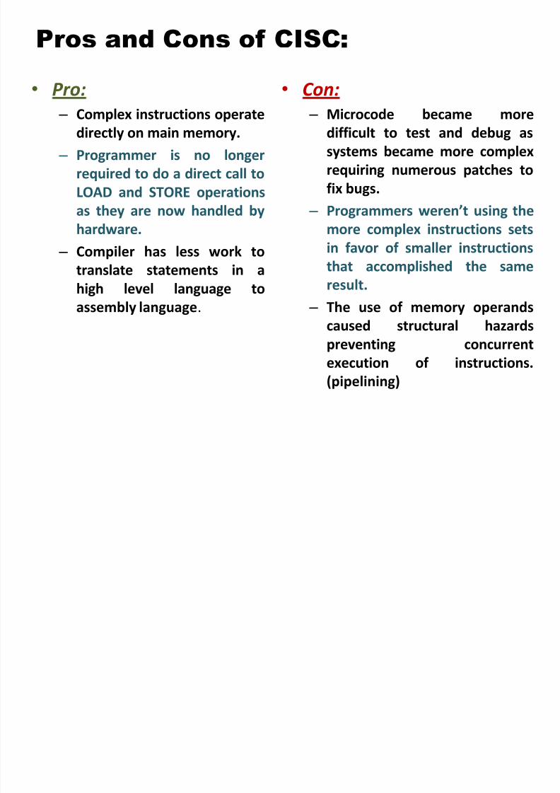
Pros and Cons of CISC:
• Pro:
– Complex instructions operate
directly on main memory.
– Programmer is no longer
required to do a direct call to
LOAD and STORE operations
as they are now handled by
hardware.
– Compiler has less work to
translate statements in a
high level language to
assembly language.
• Con:
– Microcode became more
difficult to test and debug as
systems became more complex
requiring numerous patches to
fix bugs.
– Programmers weren’t using the
more complex instructions sets
in favor of smaller instructions
that accomplished the same
result.
– The use of memory operands
caused structural hazards
preventing concurrent
execution of instructions.
(pipelining)
8/2/2019 Chap6 Micro Processors
http://slidepdf.com/reader/full/chap6-micro-processors 58/123
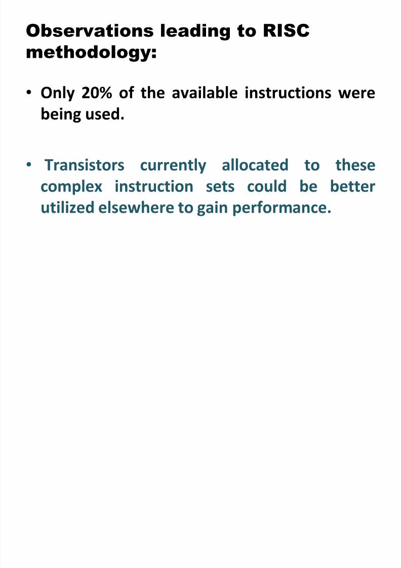
• Only 20% of the available instructions were
being used.
• Transistors currently allocated to these
complex instruction sets could be better
utilized elsewhere to gain performance.
Observations leading to RISC
methodology:
8/2/2019 Chap6 Micro Processors
http://slidepdf.com/reader/full/chap6-micro-processors 59/123
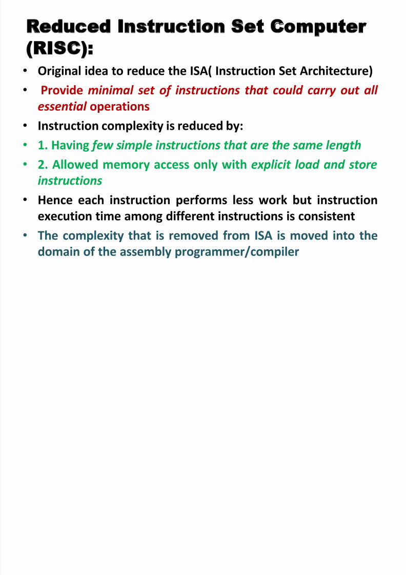
Reduced Instruction Set Computer
(RISC): •
Original idea to reduce the ISA( Instruction Set Architecture)• Provide minimal set of instructions that could carry out all
essential operations
• Instruction complexity is reduced by:
•1. Having few simple instructions that are the same length
• 2. Allowed memory access only with explicit load and store
instructions
• Hence each instruction performs less work but instruction
execution time among different instructions is consistent• The complexity that is removed from ISA is moved into the
domain of the assembly programmer/compiler
8/2/2019 Chap6 Micro Processors
http://slidepdf.com/reader/full/chap6-micro-processors 60/123
Reduced Instruction Set Computer
8/2/2019 Chap6 Micro Processors
http://slidepdf.com/reader/full/chap6-micro-processors 61/123
(RISC):
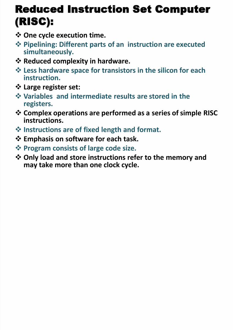
One cycle execution time.
Pipelining: Different parts of an instruction are executedsimultaneously.
Reduced complexity in hardware.
Less hardware space for transistors in the silicon for eachinstruction.
Large register set: Variables and intermediate results are stored in the
registers.
Complex operations are performed as a series of simple RISCinstructions.
Instructions are of fixed length and format.
Emphasis on software for each task.
Program consists of large code size.
Only load and store instructions refer to the memory and
may take more than one clock cycle.

8/2/2019 Chap6 Micro Processors
http://slidepdf.com/reader/full/chap6-micro-processors 62/123
• RISC uses only register to register operations
• Only LOAD and STORE operations have access to
memory
• Separation of LOAD and STORE instructions allowsthe compiler to shift these operations around for
maximum efficiency during execution.
• Simple instructions require fewer transistors which
make the chips easier to design and cheaper to
produce
Advantages of RISC:
8/2/2019 Chap6 Micro Processors
http://slidepdf.com/reader/full/chap6-micro-processors 63/123
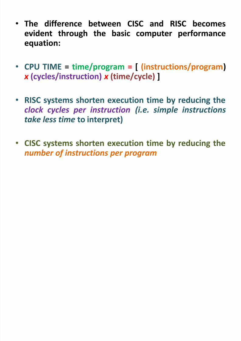
• The difference between CISC and RISC becomesevident through the basic computer performance
equation:
• CPU TIME = time/program = [ (instructions/program) x (cycles/instruction) x (time/cycle) ]
• RISC systems shorten execution time by reducing theclock cycles per instruction (i.e. simple instructionstake less time to interpret)
• CISC systems shorten execution time by reducing thenumber of instructions per program

8/2/2019 Chap6 Micro Processors
http://slidepdf.com/reader/full/chap6-micro-processors 64/123
RISC:
To multiply two numbers, firstload each operand from a
location in main memory
(locations 1:1 through 6:4) into
one of the six registers (A, B,
C, D, E, or F). Once loaded,
they can be multiplied by the
execution unit (or ALU).
1. LOAD [A, 2:3]2. LOAD [B, 5:2]
3. MULT [A, B]
4. STORE [2:3, A]
8/2/2019 Chap6 Micro Processors
http://slidepdf.com/reader/full/chap6-micro-processors 65/123
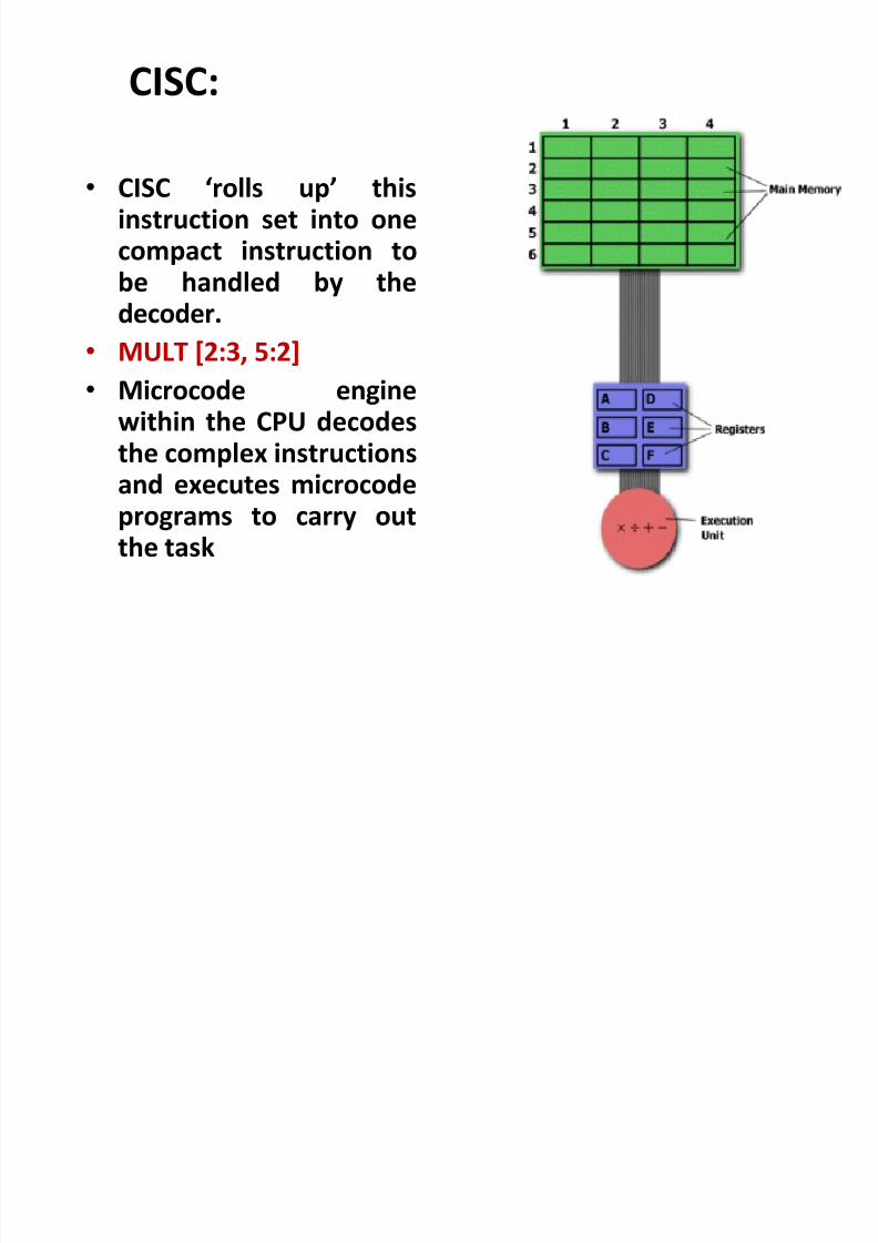
CISC:
• CISC ‘rolls up’ thisinstruction set into onecompact instruction tobe handled by the
decoder.• MULT [2:3, 5:2]
• Microcode enginewithin the CPU decodesthe complex instructionsand executes microcodeprograms to carry outthe task
8/2/2019 Chap6 Micro Processors
http://slidepdf.com/reader/full/chap6-micro-processors 66/123
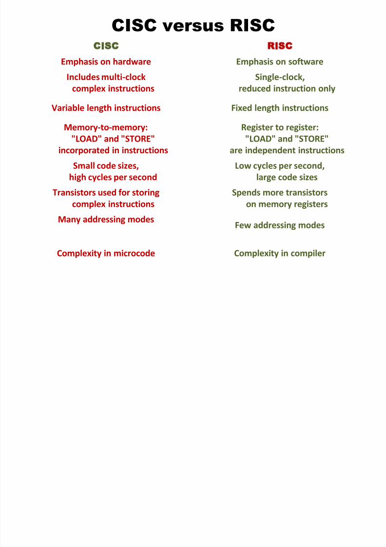
CISC versus RISC
8/2/2019 Chap6 Micro Processors
http://slidepdf.com/reader/full/chap6-micro-processors 67/123
CISC versus RISCCISC RISC
Emphasis on hardware Emphasis on software
Includes multi-clock
complex instructions
Single-clock,
reduced instruction only
Variable length instructions Fixed length instructions
Memory-to-memory:
"LOAD" and "STORE"incorporated in instructions
Register to register:
"LOAD" and "STORE"are independent instructions
Small code sizes,
high cycles per second
Low cycles per second,
large code sizes
Transistors used for storing
complex instructions
Spends more transistors
on memory registersMany addressing modes
Few addressing modes
Complexity in microcode Complexity in compiler
8/2/2019 Chap6 Micro Processors
http://slidepdf.com/reader/full/chap6-micro-processors 68/123
Binary & Decimal Numbers:
BINARY
(BASE 2)
numbers
8/2/2019 Chap6 Micro Processors
http://slidepdf.com/reader/full/chap6-micro-processors 69/123
DECIMAL
(BASE 10)
numbers
8/2/2019 Chap6 Micro Processors
http://slidepdf.com/reader/full/chap6-micro-processors 70/123
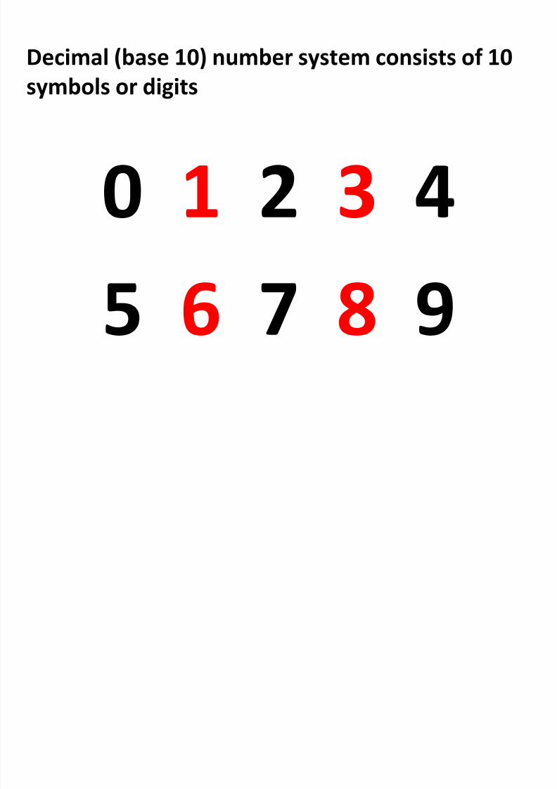
Decimal (base 10) number system consists of 10
symbols or digits
0 1 2 3 4
5 6 7 8 9
8/2/2019 Chap6 Micro Processors
http://slidepdf.com/reader/full/chap6-micro-processors 71/123
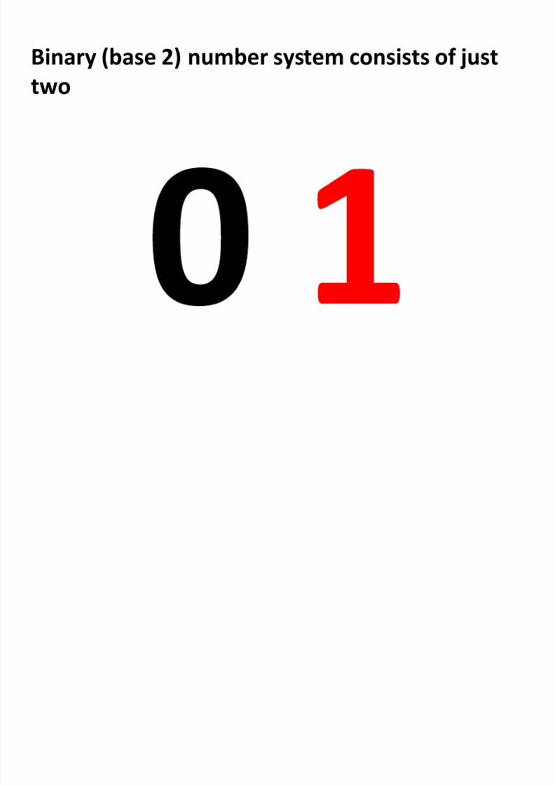
Binary (base 2) number system consists of just
two
Oth l b t
8/2/2019 Chap6 Micro Processors
http://slidepdf.com/reader/full/chap6-micro-processors 72/123
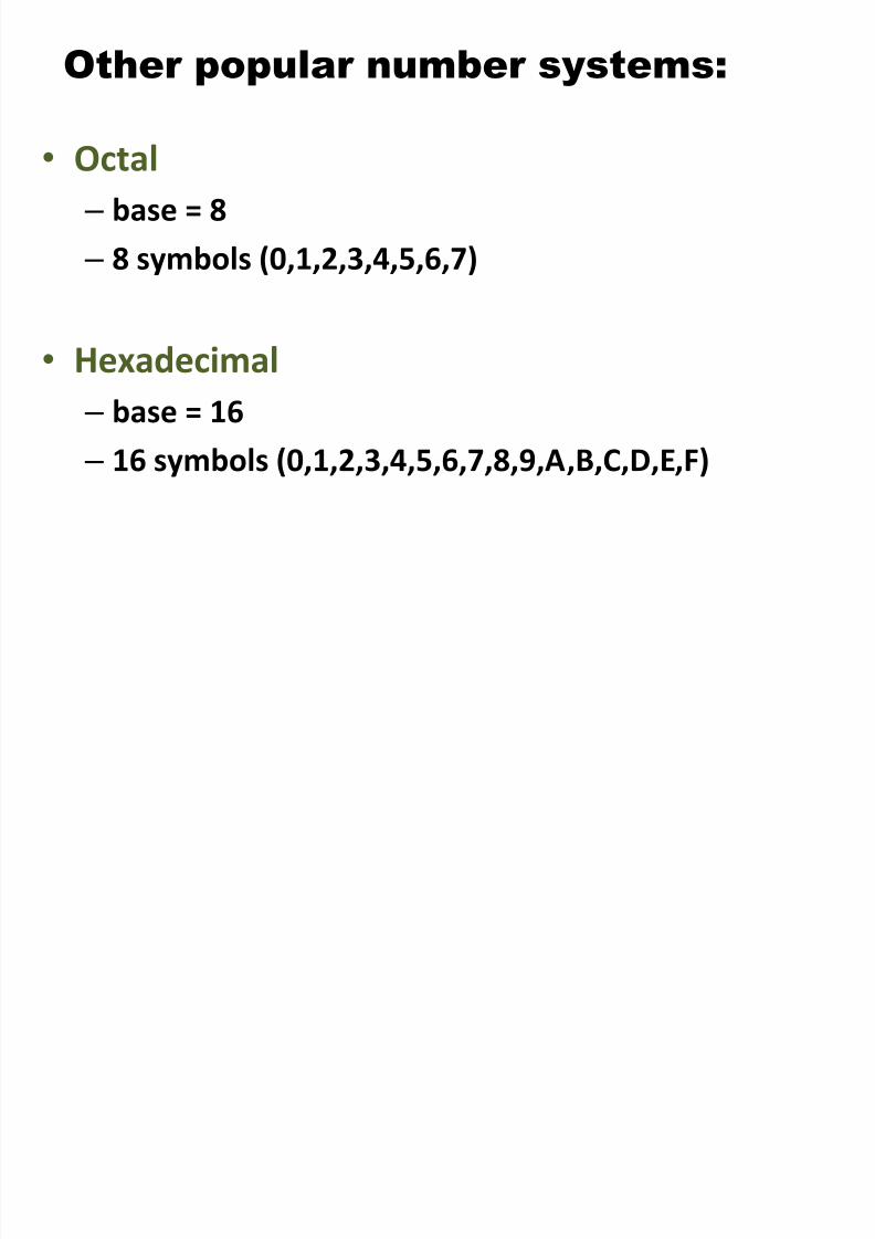
Other popular number systems:
•Octal – base = 8
– 8 symbols (0,1,2,3,4,5,6,7)
• Hexadecimal
– base = 16
–
16 symbols (0,1,2,3,4,5,6,7,8,9,A,B,C,D,E,F)
8/2/2019 Chap6 Micro Processors
http://slidepdf.com/reader/full/chap6-micro-processors 73/123
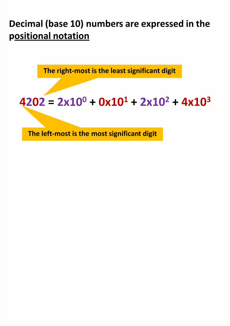
Decimal (base 10) numbers are expressed in the
positional notation
4202 = 2x100 + 0x101 + 2x10² + 4x10³
The right-most is the least significant digit
The left-most is the most significant digit
8/2/2019 Chap6 Micro Processors
http://slidepdf.com/reader/full/chap6-micro-processors 74/123
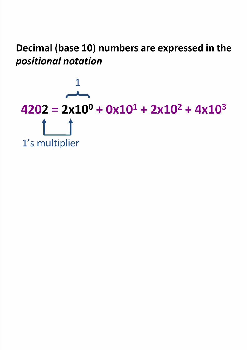
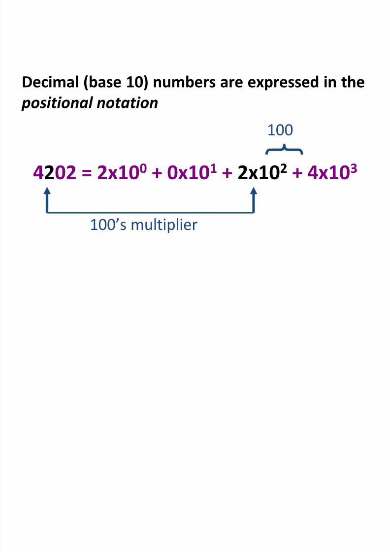
Decimal (base 10) numbers are expressed in the positional notation
4202 = 2x100 + 0x101 + 2x10² + 4x10³
1’s multiplier
1
8/2/2019 Chap6 Micro Processors
http://slidepdf.com/reader/full/chap6-micro-processors 75/123
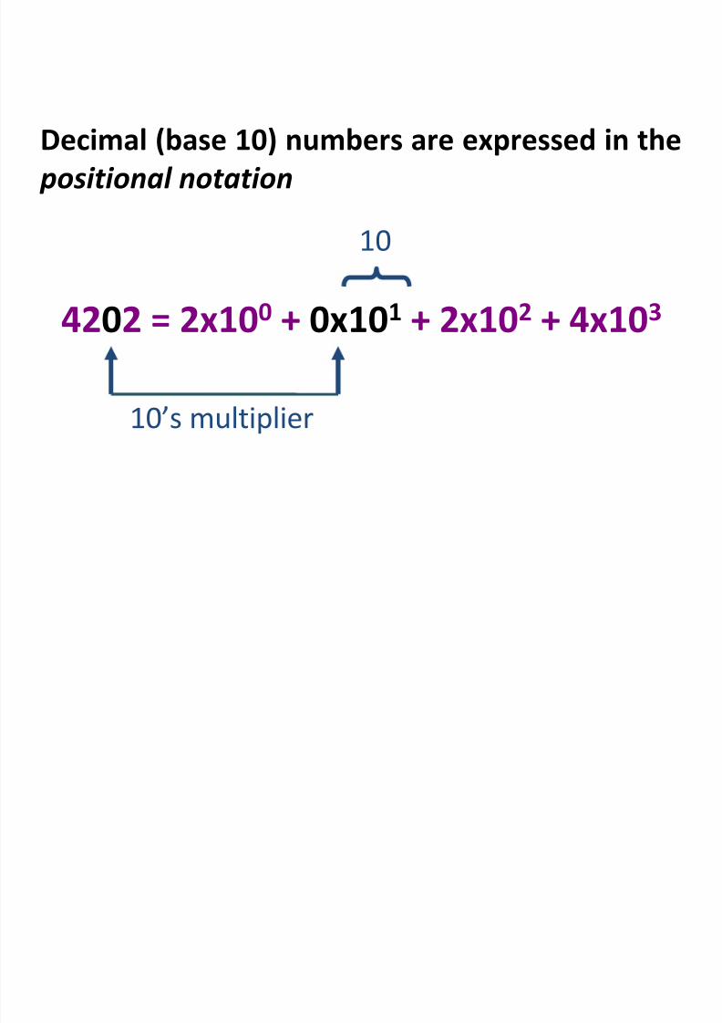
Decimal (base 10) numbers are expressed in the positional notation
4202 = 2x100 + 0x101 + 2x10² + 4x10³
10’s multiplier
10
8/2/2019 Chap6 Micro Processors
http://slidepdf.com/reader/full/chap6-micro-processors 76/123
8/2/2019 Chap6 Micro Processors
http://slidepdf.com/reader/full/chap6-micro-processors 77/123
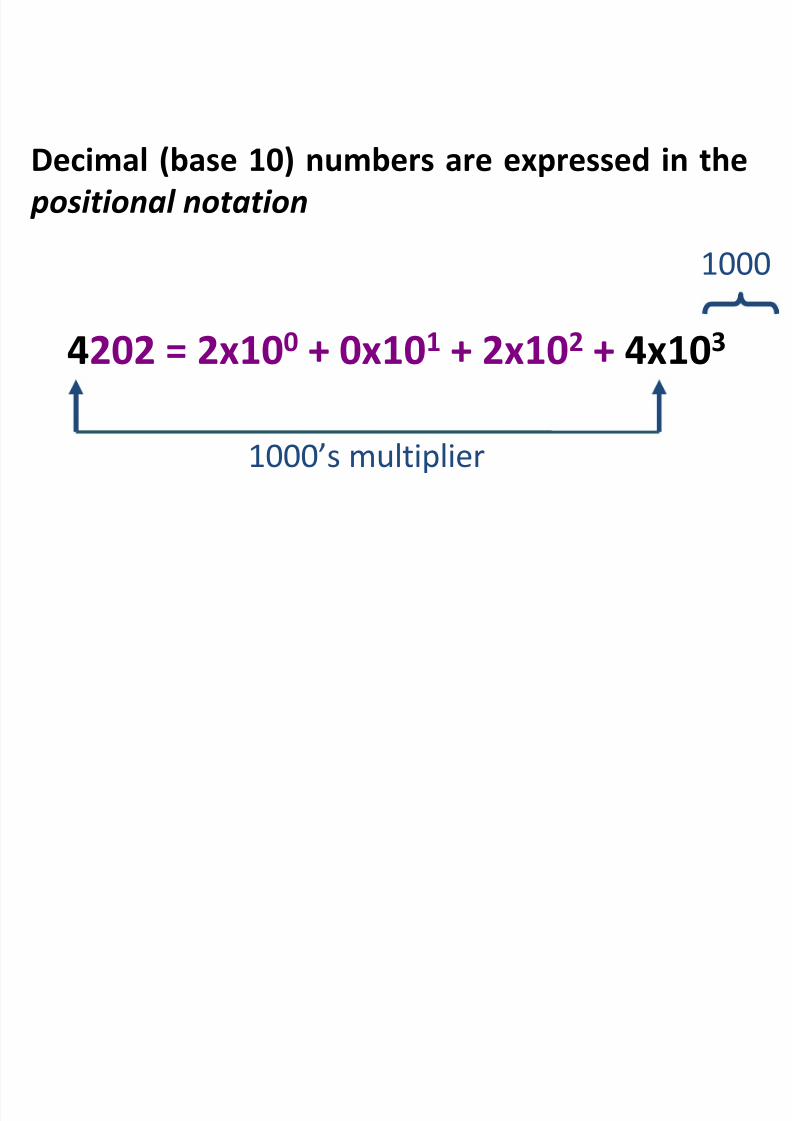
Decimal (base 10) numbers are expressed in the positional notation
4202 = 2x100 + 0x101 + 2x10² + 4x10³
1000’s multiplier
1000
8/2/2019 Chap6 Micro Processors
http://slidepdf.com/reader/full/chap6-micro-processors 78/123
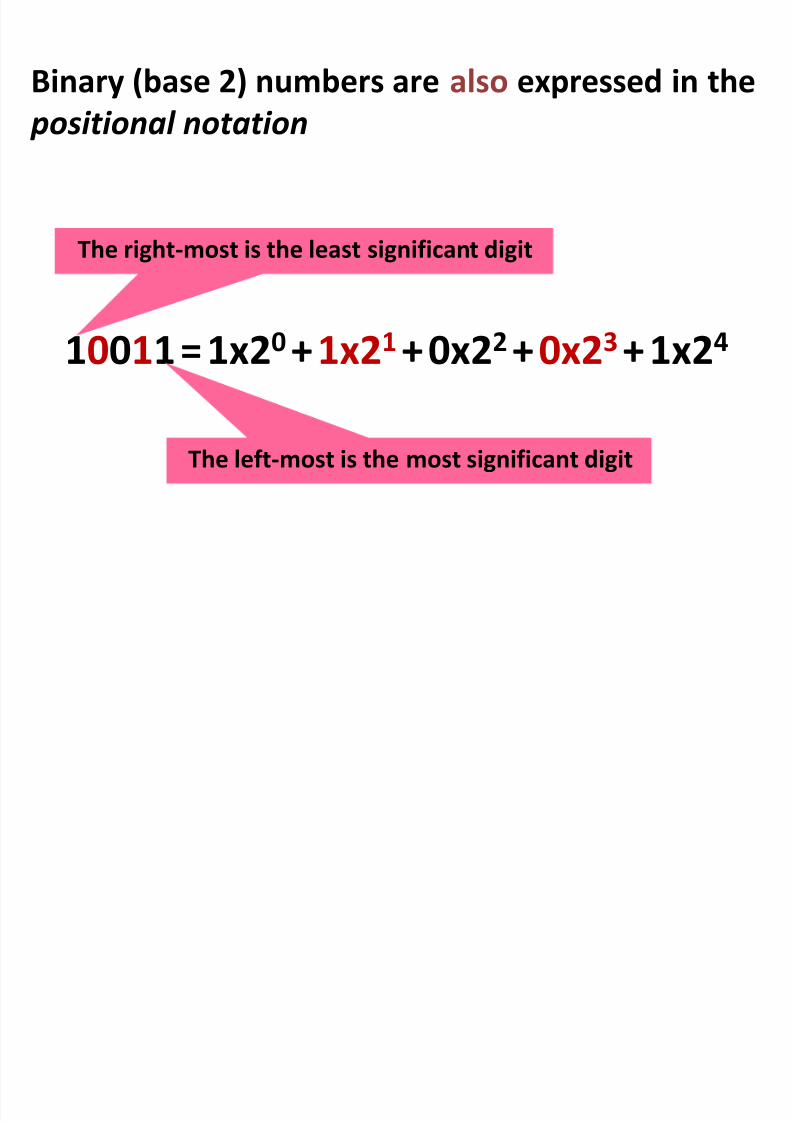
Binary (base 2) numbers are also expressed in the
positional notation
10011 = 1x20 + 1x21
+ 0x22 + 0x23
+ 1x24
The right-most is the least significant digit
The left-most is the most significant digit
8/2/2019 Chap6 Micro Processors
http://slidepdf.com/reader/full/chap6-micro-processors 79/123
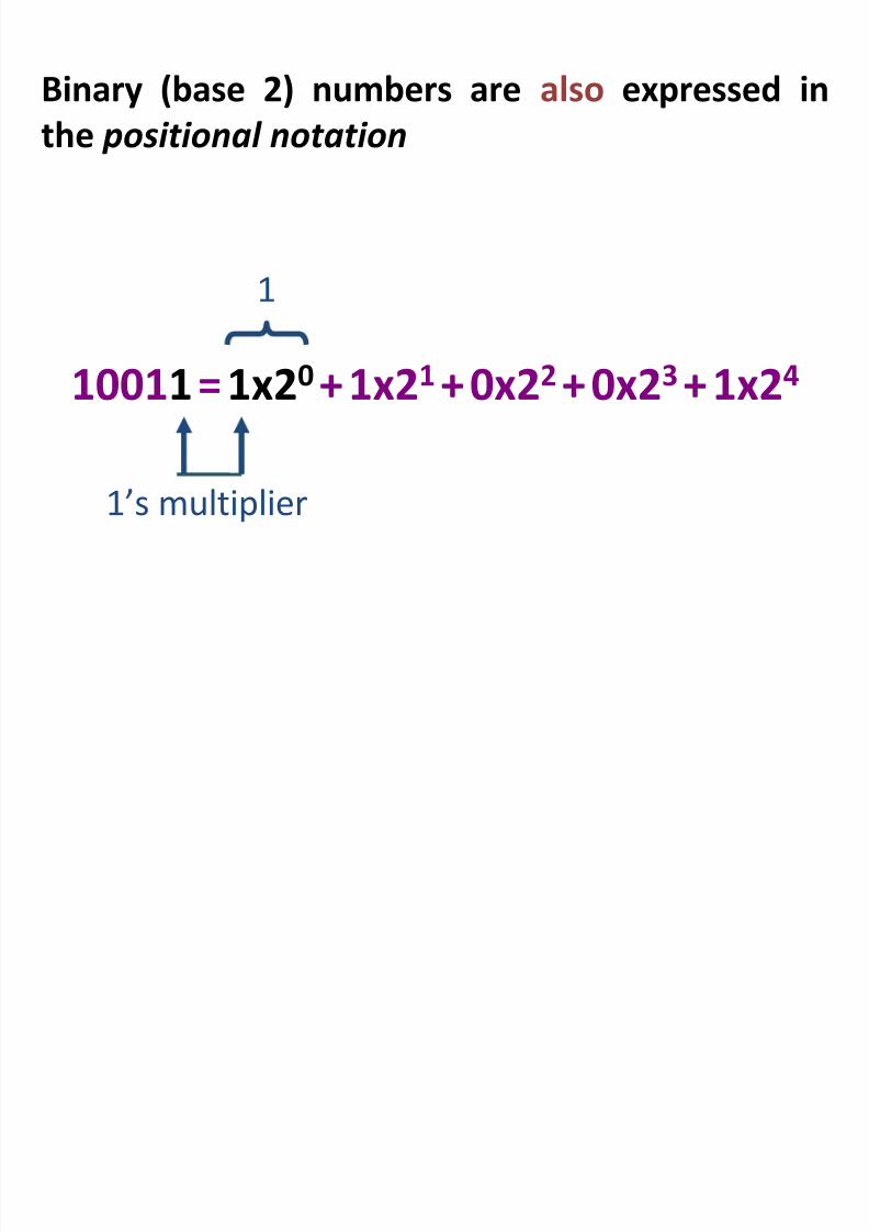
Binary (base 2) numbers are also expressed in
the positional notation
10011 = 1x20 + 1x21
+ 0x22 + 0x23
+ 1x24
1’s multiplier
1
8/2/2019 Chap6 Micro Processors
http://slidepdf.com/reader/full/chap6-micro-processors 80/123
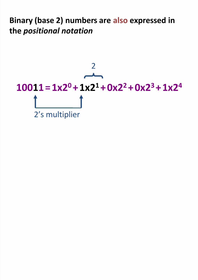
Binary (base 2) numbers are also expressed in
the positional notation
10011 = 1x20 + 1x21
+ 0x22 + 0x23
+ 1x24
2’s multiplier
2
8/2/2019 Chap6 Micro Processors
http://slidepdf.com/reader/full/chap6-micro-processors 81/123
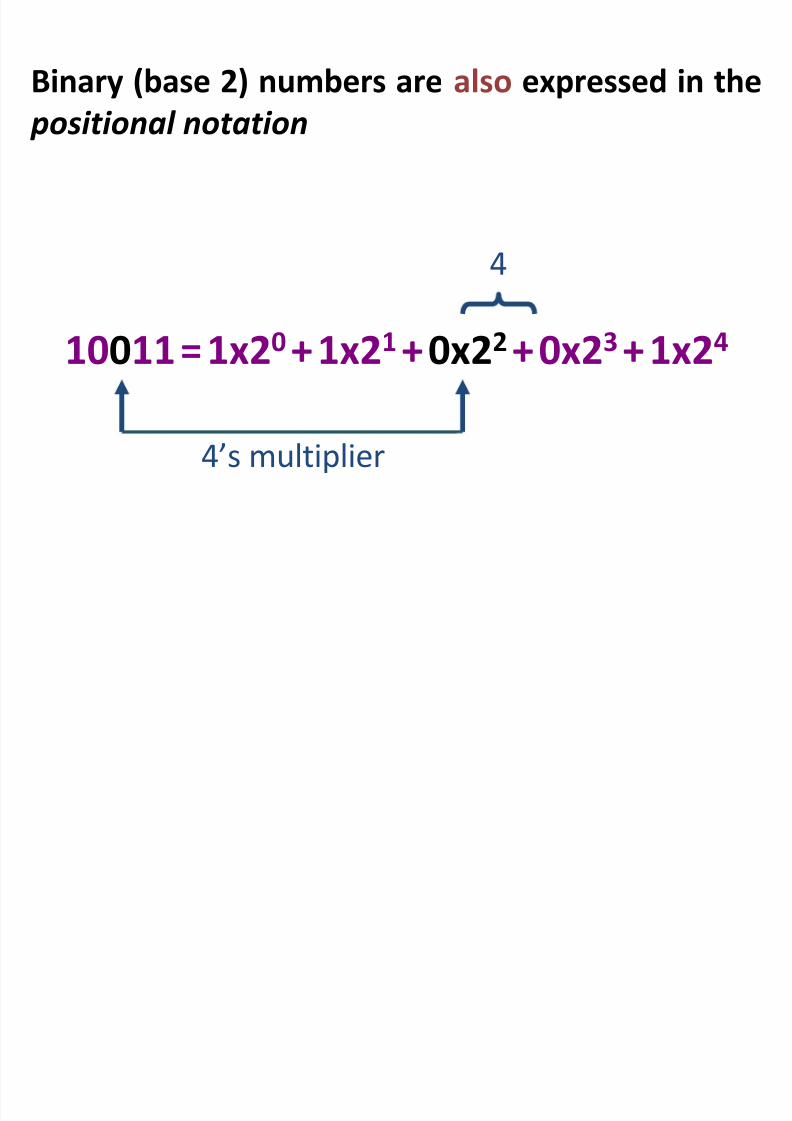
Binary (base 2) numbers are also expressed in the
positional notation
10011 = 1x20 + 1x21
+ 0x22 + 0x23
+ 1x24
4’s multiplier
4

8/2/2019 Chap6 Micro Processors
http://slidepdf.com/reader/full/chap6-micro-processors 82/123
Binary (base 2) numbers are also expressed inthe positional notation
10011 = 1x20 + 1x21
+ 0x22 + 0x23
+ 1x24
8’s multiplier
8
8/2/2019 Chap6 Micro Processors
http://slidepdf.com/reader/full/chap6-micro-processors 83/123
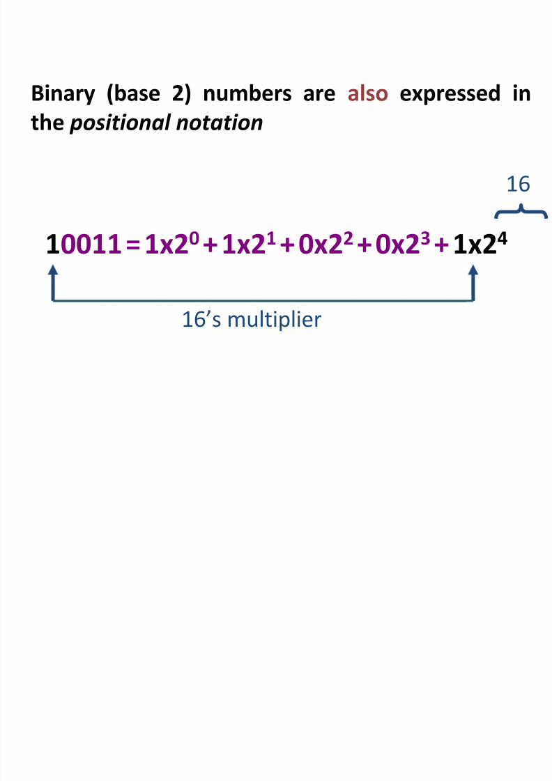
Binary (base 2) numbers are also expressed in
the positional notation
10011 = 1x20 + 1x21
+ 0x22 + 0x23
+ 1x24
16’s multiplier
16
8/2/2019 Chap6 Micro Processors
http://slidepdf.com/reader/full/chap6-micro-processors 84/123
Why binary ?Because this system is natural for digital computers
The fundamental building block of a digital computer –
the switch – possesses two natural states, ON & OFF.
It is natural to represent those states in a number system
that has only two symbols, 1 and 0, i.e. the binary
number system
8/2/2019 Chap6 Micro Processors
http://slidepdf.com/reader/full/chap6-micro-processors 85/123
Decimal Binaryconversion
8/2/2019 Chap6 Micro Processors
http://slidepdf.com/reader/full/chap6-micro-processors 86/123
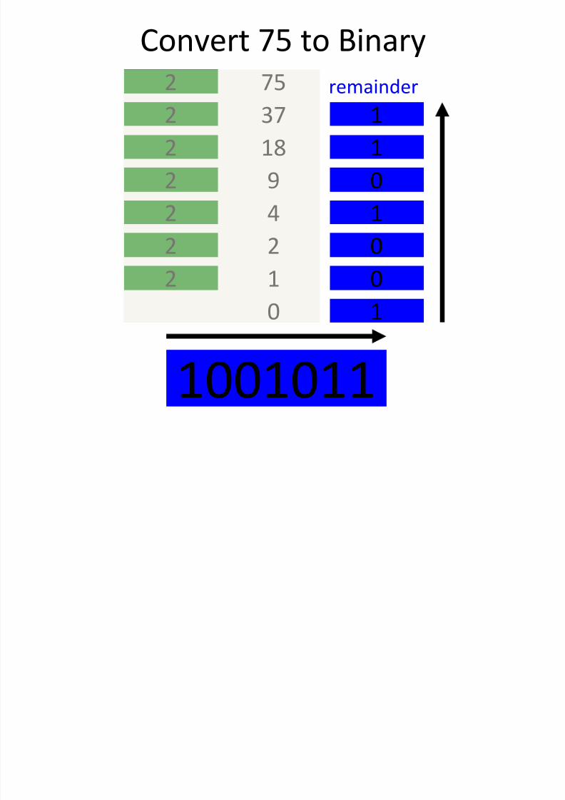
Check

8/2/2019 Chap6 Micro Processors
http://slidepdf.com/reader/full/chap6-micro-processors 87/123
Check
1001011 = 1x20 + 1x21 + 0x22 + 1x23 +
0x24 + 0x25
+ 1x26
= 1 + 2 + 0 + 8 + 0 + 0 + 64
= 75
Convert 100 to Binary

8/2/2019 Chap6 Micro Processors
http://slidepdf.com/reader/full/chap6-micro-processors 88/123
Convert 100 to Binary
1002
50 02
25 02
12 12
6 02
3 02
1 12
0 1
1100100
remainder
8/2/2019 Chap6 Micro Processors
http://slidepdf.com/reader/full/chap6-micro-processors 89/123
Logic Gates
8/2/2019 Chap6 Micro Processors
http://slidepdf.com/reader/full/chap6-micro-processors 90/123
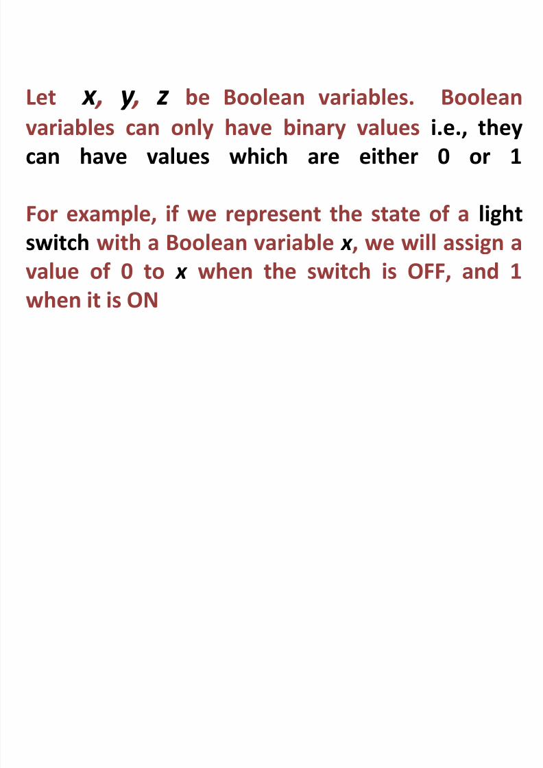
Let x , y , z be Boolean variables. Booleanvariables can only have binary values i.e., they
can have values which are either 0 or 1
For example, if we represent the state of a light
switch with a Boolean variable x , we will assign a
value of 0 to x when the switch is OFF, and 1
when it is ON
A f th f th t t f

8/2/2019 Chap6 Micro Processors
http://slidepdf.com/reader/full/chap6-micro-processors 91/123
A few other names for the states of
these Boolean variables
0 1
Off On
Low High
False True
8/2/2019 Chap6 Micro Processors
http://slidepdf.com/reader/full/chap6-micro-processors 92/123
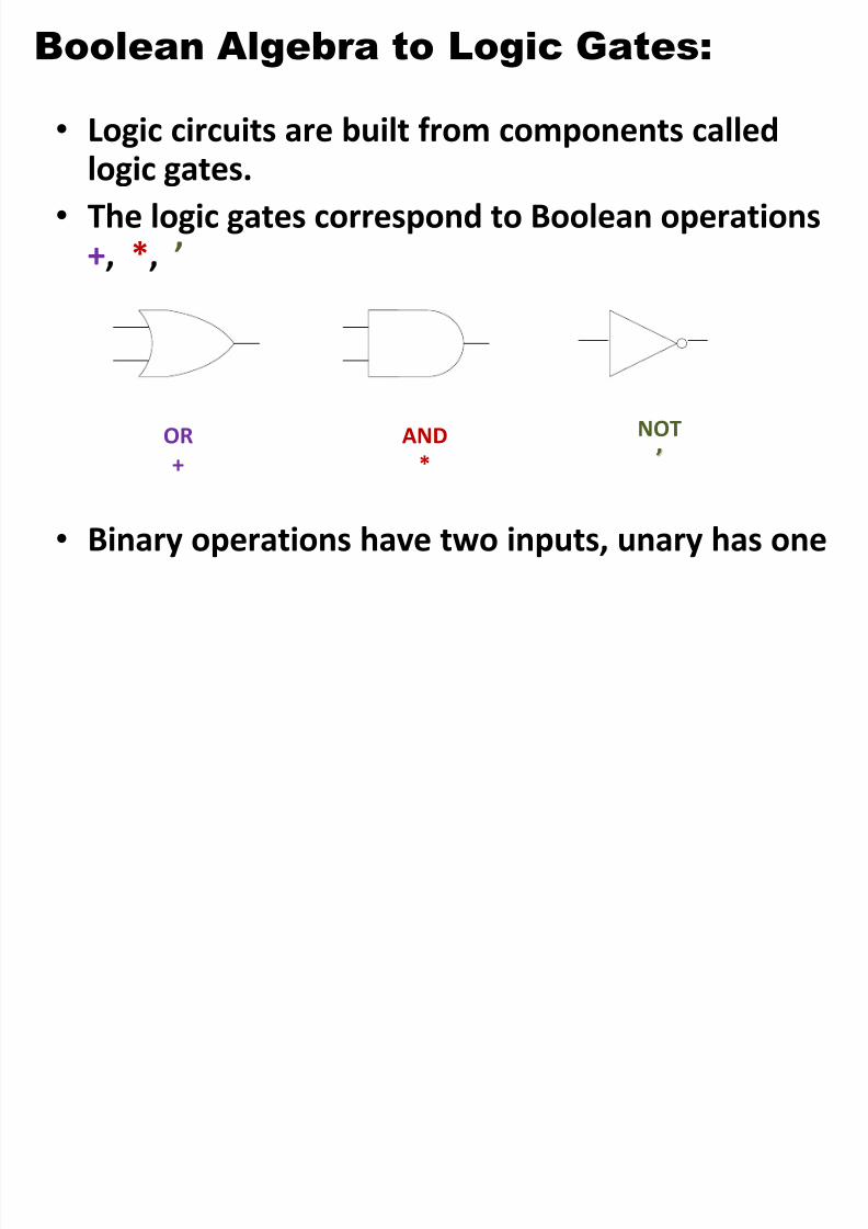
Boolean Algebra to Logic Gates:
8/2/2019 Chap6 Micro Processors
http://slidepdf.com/reader/full/chap6-micro-processors 93/123
• Logic circuits are built from components called
logic gates.• The logic gates correspond to Boolean operations
+, *, ’
• Binary operations have two inputs, unary has one
OR
+
AND
*
NOT
’

8/2/2019 Chap6 Micro Processors
http://slidepdf.com/reader/full/chap6-micro-processors 94/123
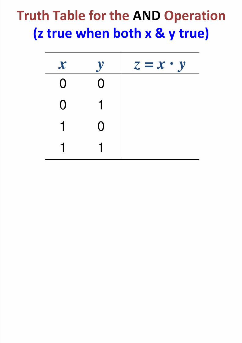
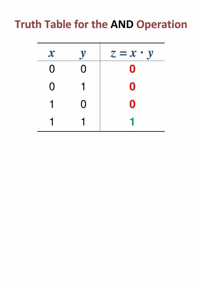
Truth Table for the AND Operation
8/2/2019 Chap6 Micro Processors
http://slidepdf.com/reader/full/chap6-micro-processors 95/123
p
(z true when both x & y true)
x y z = x · y
0 0
0 1
1 0
1 1
8/2/2019 Chap6 Micro Processors
http://slidepdf.com/reader/full/chap6-micro-processors 96/123
8/2/2019 Chap6 Micro Processors
http://slidepdf.com/reader/full/chap6-micro-processors 97/123
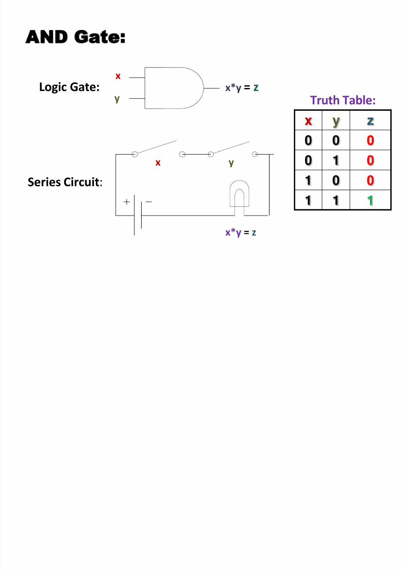
AND Gate:
x
y
x*y = z
Logic Gate:
Series Circuit:
x y
x y z
0 0 0
0 1 0
1 0 0
1 1 1
Truth Table:x*y = z
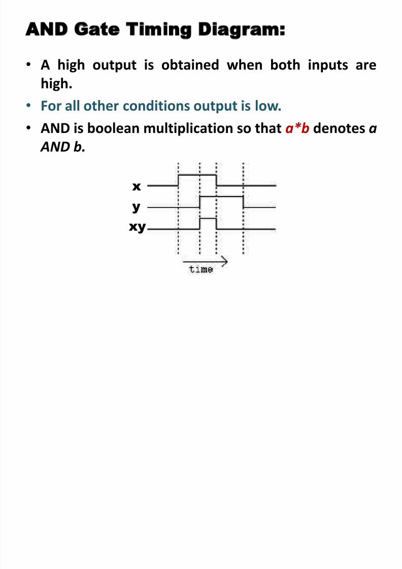
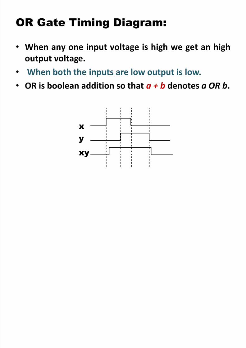
AND Gate Timing Diagram:
8/2/2019 Chap6 Micro Processors
http://slidepdf.com/reader/full/chap6-micro-processors 98/123
• A high output is obtained when both inputs are
high.
• For all other conditions output is low.
• AND is boolean multiplication so that a*b denotes a
AND b.
x
y
xy

8/2/2019 Chap6 Micro Processors
http://slidepdf.com/reader/full/chap6-micro-processors 99/123
OR Gate
Truth Table for the OR Operation
8/2/2019 Chap6 Micro Processors
http://slidepdf.com/reader/full/chap6-micro-processors 100/123
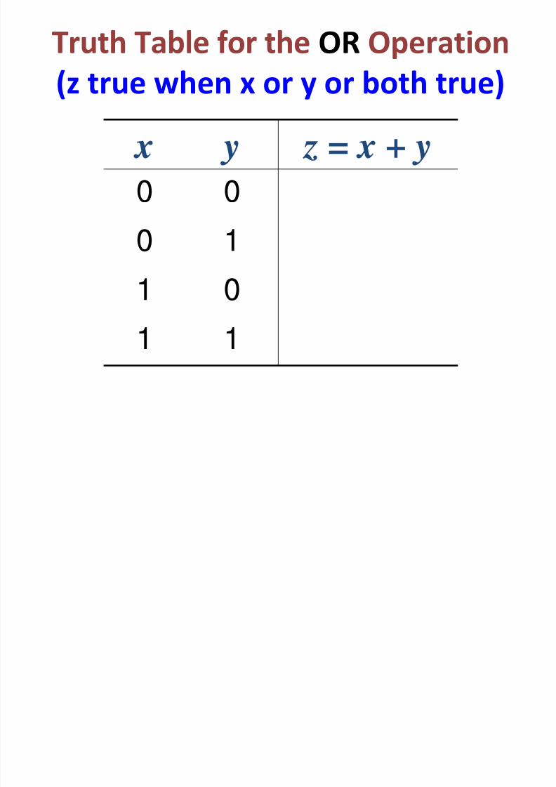
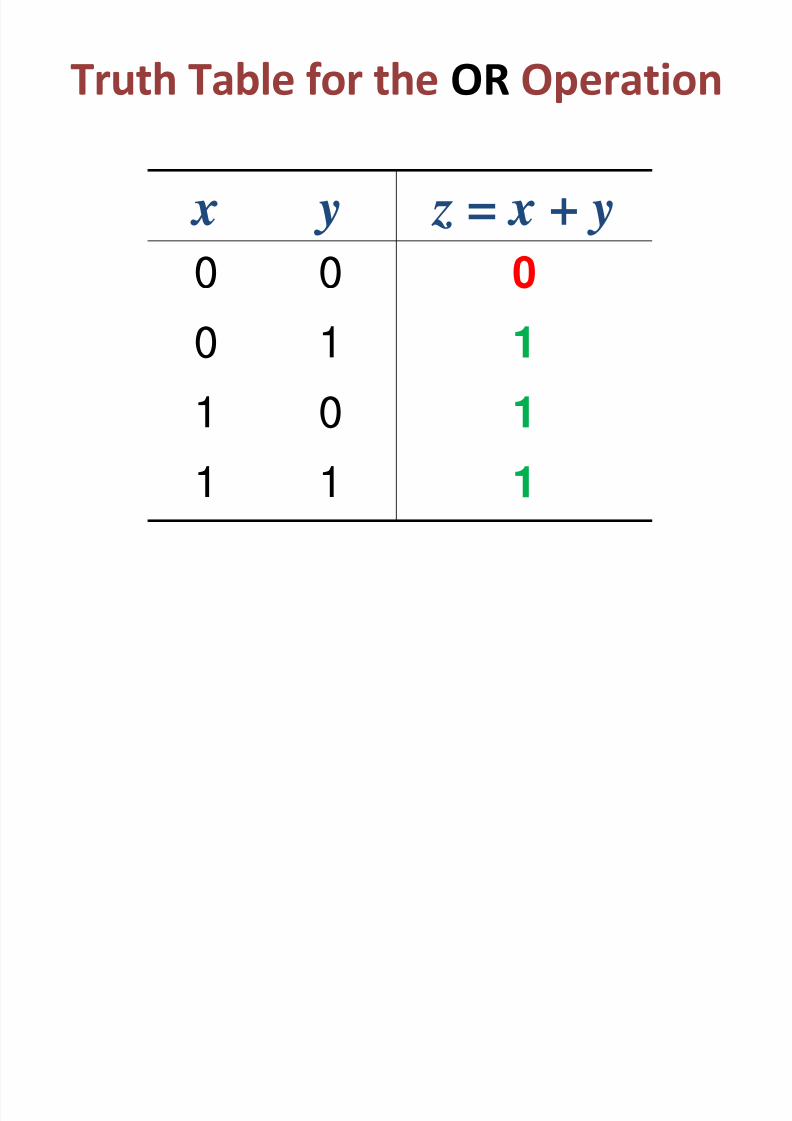
Truth Table for the OR Operation
(z true when x or y or both true)
x y z = x + y
0 0
0 1
1 0
1 1
Truth Table for the OR Operation
8/2/2019 Chap6 Micro Processors
http://slidepdf.com/reader/full/chap6-micro-processors 101/123
Truth Table for the OR Operation
x y z = x + y
0 00
0 1 1
1 01
1 1 1
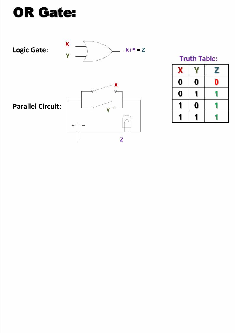
OR Gate:
8/2/2019 Chap6 Micro Processors
http://slidepdf.com/reader/full/chap6-micro-processors 102/123
XY
Z
Logic Gate:
Parallel Circuit:
X
Y
X Y Z
0 0 0
0 1 1
1 0 1
1 1 1
Truth Table:
X+Y = Z
8/2/2019 Chap6 Micro Processors
http://slidepdf.com/reader/full/chap6-micro-processors 103/123

8/2/2019 Chap6 Micro Processors
http://slidepdf.com/reader/full/chap6-micro-processors 104/123
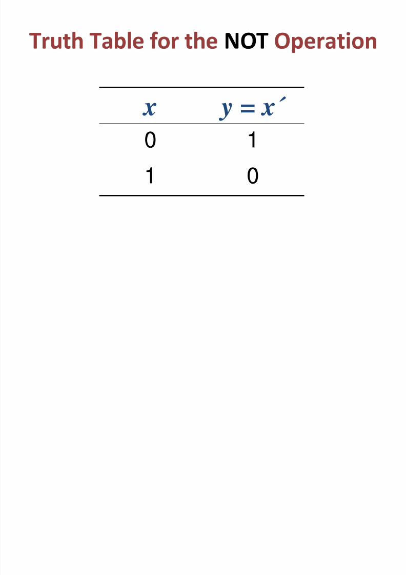
Truth Table for the NOT Operation
8/2/2019 Chap6 Micro Processors
http://slidepdf.com/reader/full/chap6-micro-processors 105/123
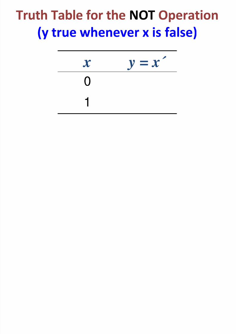
(y true whenever x is false)
x y = x´
0
1
Truth Table for the NOT Operation
8/2/2019 Chap6 Micro Processors
http://slidepdf.com/reader/full/chap6-micro-processors 106/123
Truth Table for the NOT Operation
x y = x´
0 1
1 0
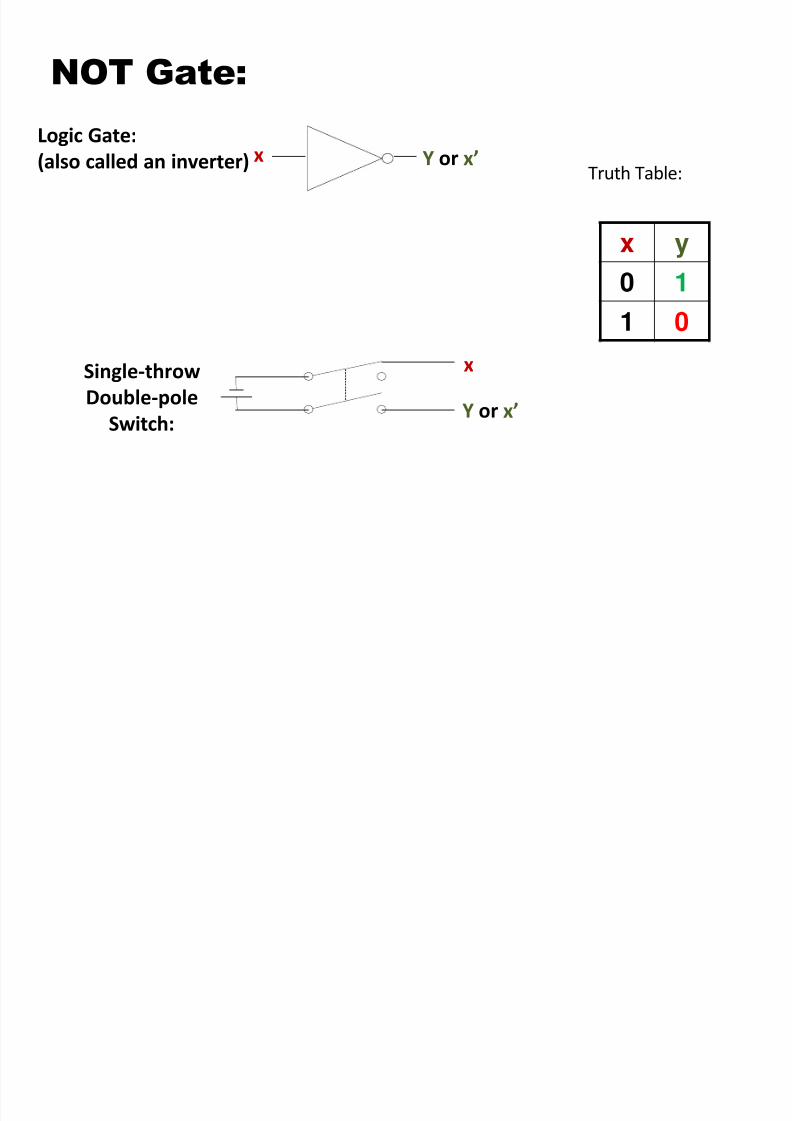
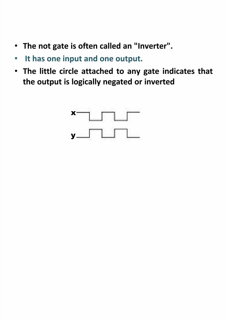
NOT Gate:
8/2/2019 Chap6 Micro Processors
http://slidepdf.com/reader/full/chap6-micro-processors 107/123
NOT Gate:
x
Y or x’
Logic Gate:
(also called an inverter)
Single-throw
Double-pole
Switch:
x
x y
0 11 0
Truth Table:Y or x’
8/2/2019 Chap6 Micro Processors
http://slidepdf.com/reader/full/chap6-micro-processors 108/123
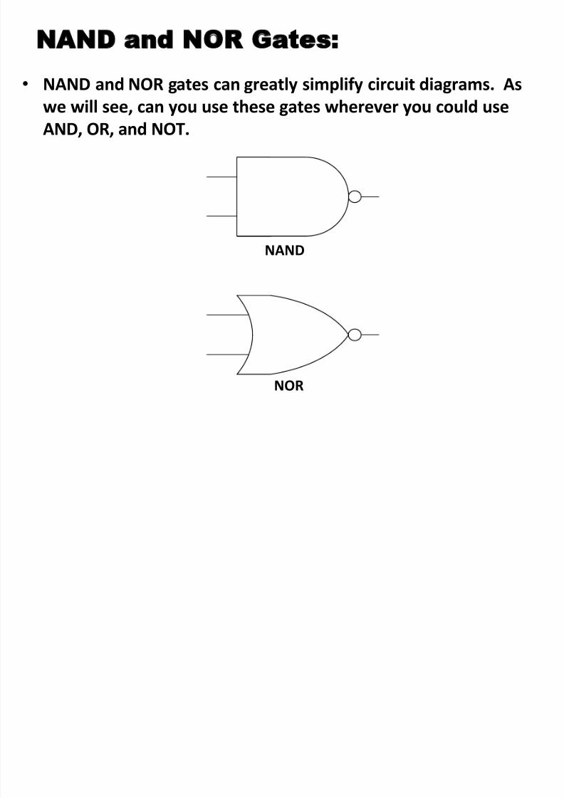
NAND and NOR Gates:
8/2/2019 Chap6 Micro Processors
http://slidepdf.com/reader/full/chap6-micro-processors 109/123
• NAND and NOR gates can greatly simplify circuit diagrams. As
we will see, can you use these gates wherever you could useAND, OR, and NOT.
NAND
NOR

8/2/2019 Chap6 Micro Processors
http://slidepdf.com/reader/full/chap6-micro-processors 110/123
NAND Gate
NAND Gate :
8/2/2019 Chap6 Micro Processors
http://slidepdf.com/reader/full/chap6-micro-processors 111/123
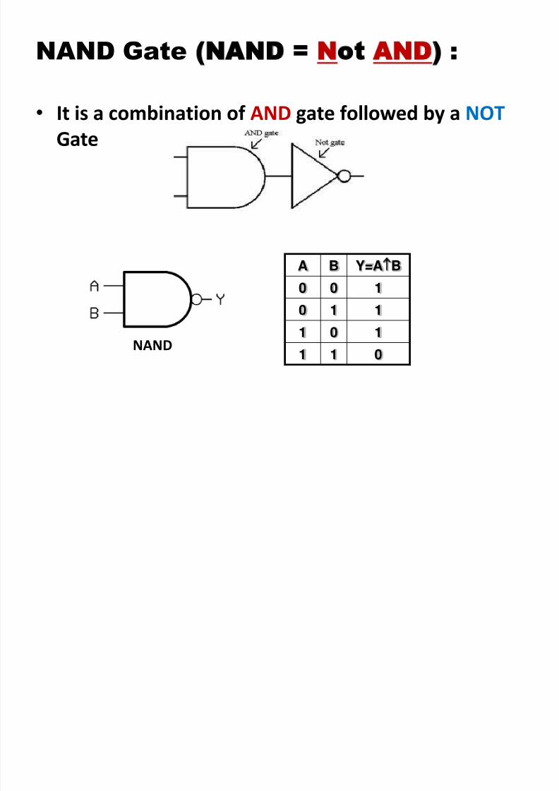
NAND Gate (NAND = Not AND) :
• It is a combination of AND gate followed by a NOT Gate
NAND
A B Y=AB
0 0 1
0 1 1
1 0 1
1 1 0
NAND Gate Timing Diagram:
8/2/2019 Chap6 Micro Processors
http://slidepdf.com/reader/full/chap6-micro-processors 112/123
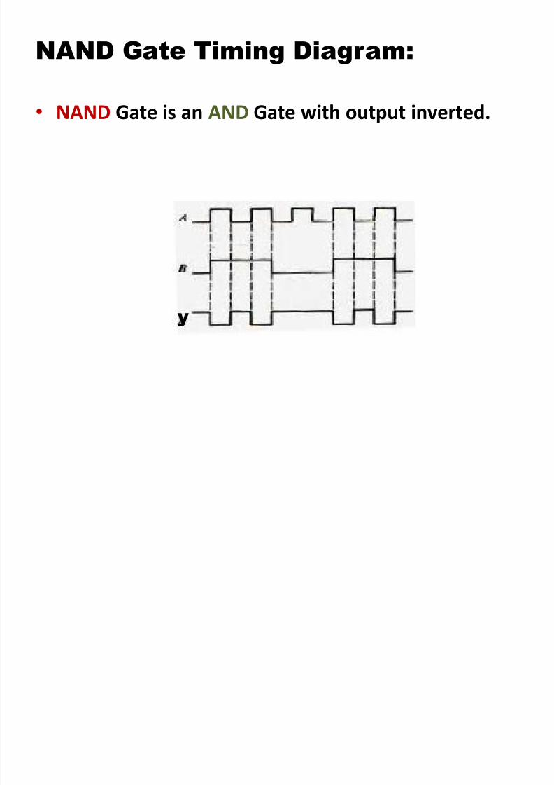
NAND Gate Timing Diagram:
• NAND Gate is an AND Gate with output inverted.
y

8/2/2019 Chap6 Micro Processors
http://slidepdf.com/reader/full/chap6-micro-processors 113/123
NOR Gate
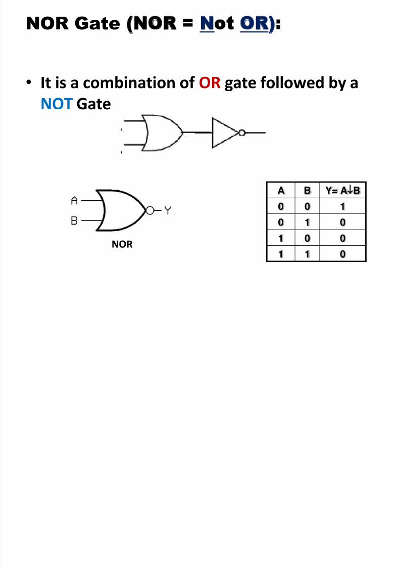
NOR Gate (NOR = Not OR):
8/2/2019 Chap6 Micro Processors
http://slidepdf.com/reader/full/chap6-micro-processors 114/123
• It is a combination of OR gate followed by aNOT Gate
A B Y= AB
0 0 1
0 1 0
1 0 0
1 1 0NOR
NOR Gate Timing Diagram:
8/2/2019 Chap6 Micro Processors
http://slidepdf.com/reader/full/chap6-micro-processors 115/123
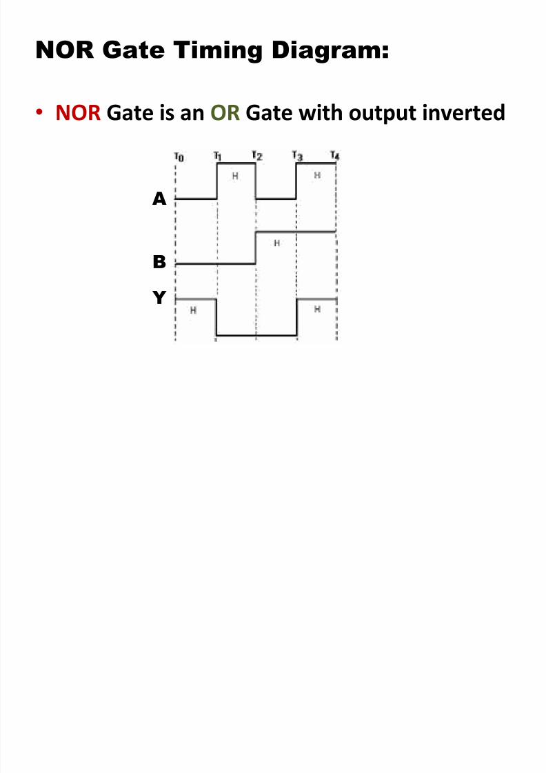
NOR Gate Timing Diagram:
• NOR Gate is an OR Gate with output inverted
Y
B
A

8/2/2019 Chap6 Micro Processors
http://slidepdf.com/reader/full/chap6-micro-processors 116/123
XOR Gate
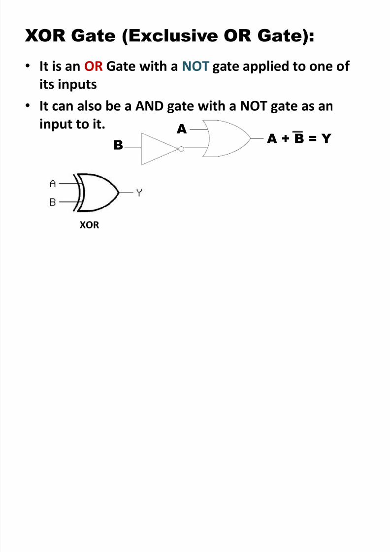
XOR Gate (Exclusive OR Gate):
8/2/2019 Chap6 Micro Processors
http://slidepdf.com/reader/full/chap6-micro-processors 117/123
( )
• It is an OR Gate with a NOT gate applied to one of
its inputs
• It can also be a AND gate with a NOT gate as an
input to it.
XOR
A
B A + B = Y
_
Truth Table for the XOR Operation
8/2/2019 Chap6 Micro Processors
http://slidepdf.com/reader/full/chap6-micro-processors 118/123
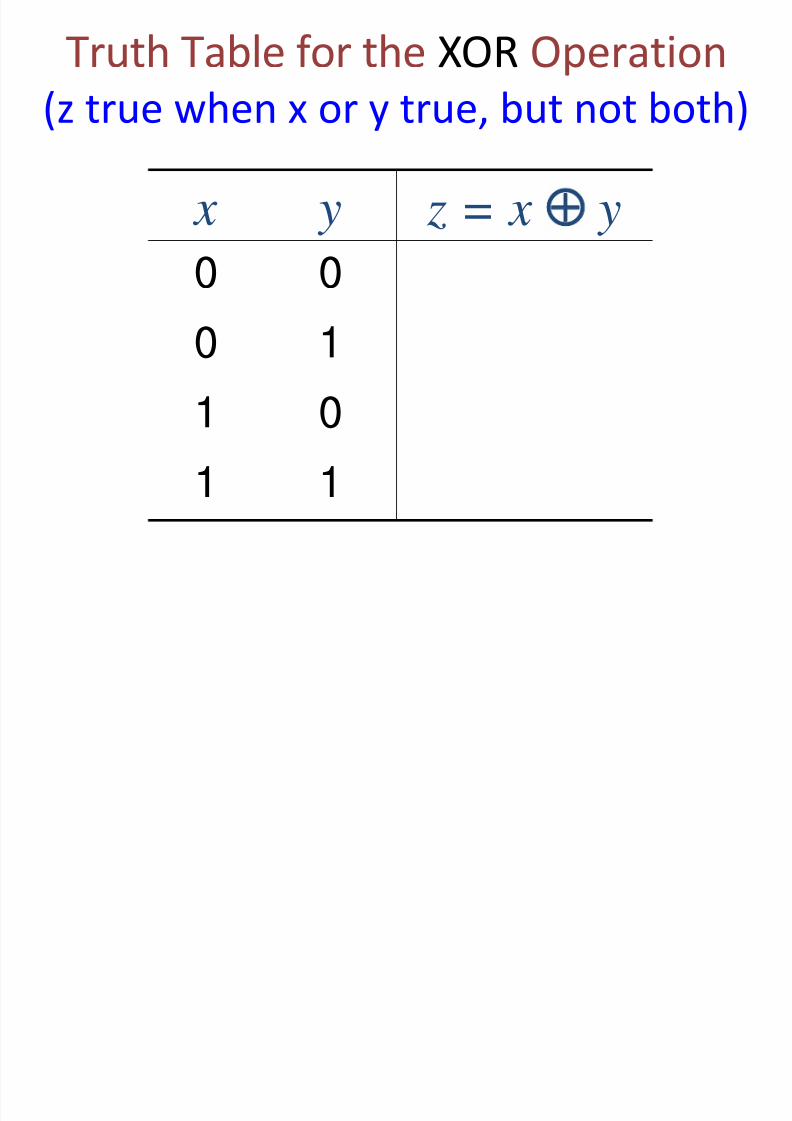
(z true when x or y true, but not both)
x y z = x y
0 0
0 1
1 0
1 1
Truth Table for the XOR Operation

8/2/2019 Chap6 Micro Processors
http://slidepdf.com/reader/full/chap6-micro-processors 119/123
Truth Table for the XOR Operation
x y z = x y
0 0 0
0 1 1
1 0 1
1 1 0
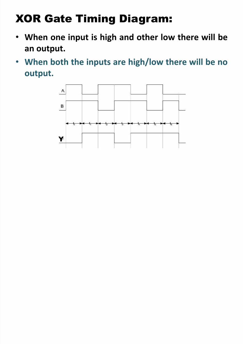
XOR Gate Timing Diagram:
8/2/2019 Chap6 Micro Processors
http://slidepdf.com/reader/full/chap6-micro-processors 120/123
• When one input is high and other low there will be
an output.• When both the inputs are high/low there will be no
output.
Y
Combining Logic Gates:

8/2/2019 Chap6 Micro Processors
http://slidepdf.com/reader/full/chap6-micro-processors 121/123
g g
8/2/2019 Chap6 Micro Processors
http://slidepdf.com/reader/full/chap6-micro-processors 122/123
122
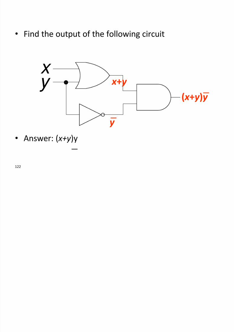
• Find the output of the following circuit
• Answer: ( x+y )y
x
y x +y
y
( x +y )y
__
8/2/2019 Chap6 Micro Processors
http://slidepdf.com/reader/full/chap6-micro-processors 123/123
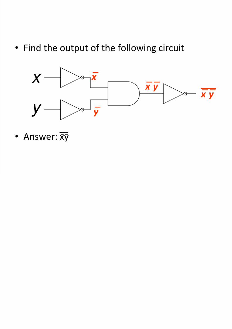
• Find the output of the following circuit
• Answer: xy
x
y
x
y
x y x y
_ _ ___