challenges in hydraulic fracture simulation: evidence from ... · evidence from observations...
TRANSCRIPT

Challenges in Hydraulic Fracture Simulation: Evidence from Observations Spanning Laboratory-Scale Experiments to Tectonic-Scale Dyke Swarms
IMA, May 2015
Andrew BungerDept of Civil and Environmental EngineeringDept of Chemical and Petroleum Engineering
University of Pittsburgh, Pittsburgh, PA, [email protected]

Role of Geometry and Propagation Regime in Multiple HF Growth
IMA, May 2015
Andrew BungerDept of Civil and Environmental EngineeringDept of Chemical and Petroleum Engineering
University of Pittsburgh, Pittsburgh, PA, [email protected]

Uniformly Stimulated Volume: The Elusive Goal
Soliman et al. , J Pet Tech, August 1990
Early 1950s frac pump, from Montgomery and Smith, J Pet Tech, December 2010
Direction drilling ad from 1954 issue of World Oil

Example from Barnett ShaleFisher et al. 2004, SPE 90051
“…regularly spaced cross-cutting fractures that tend to appear at roughly 500 ft intervals regardless of perforation cluster location.”

Success not the norm: Example from US tight sand reservoir
Mace et al. 2011. SPE 140444.

Giant Dyke Swarms- 1000s of km length
- 10s of km height
- Lateral propagation with blade-like geometry
- >119 on Earth
- >163 on Venus
- “Abundant" on Mars

Goal: Simulator to predict multiple hydraulic fracture growth versus localization
…in order to explore possible approaches to promote multiple growth
Premise: Our simulator will be consistent with basic physical principles found throughout nature and will therefore give energy-minimizing solutions
Basic Question: Can we use a 2D geometry and/or ignore fluid-solid coupling and still grasp the leading order behavior of the system?
Approach: Examine role of dimensionality of the problem and of fluid-solid coupling in energetics of the system

PI = pfo Q = Rate of energy input
PI = Sum from N HFs =Pi
If:•constant rate injection•uniformly growing array
Q=Qo, Qi=Qo/(N-1)~Qo/N, N>>1
PI=N Pi
•PI depends on N: PI=PI[N,Pi(…,Qo/N)]•Objective: Clarify nature of this dependence
Bunger AP. 2013. Analysis of the Power Input Needed to Propagate Multiple Hydraulic Fractures. International Journal of Solids and Structures, 50:1538-1549.

Input energy via the fluid and it either does work on the solid or is dissipated in fluid flow
Expression for Pi

Input energy via the fluid and it either does work on the solid or is dissipated in fluid flow
Pressure drop through perforations
Flow in fracture channel
Expression for Pi

Input energy via the fluid and it either does work on the solid or is dissipated in fluid flow
Counteract work done on crack by far field stress
Counteract work done on crack by nearby HFs
Increases elastic strain energy stored in the rock
Dissipated through rock fracturing
Expression for Pi


Radial Geometry – Viscosity Dominated Regime
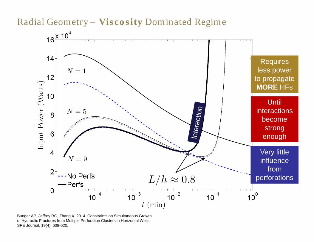
Radial Geometry – Viscosity Dominated Regime
Bunger AP, Jeffrey RG, Zhang X. 2014. Constraints on Simultaneous Growth of Hydraulic Fractures from Multiple Perforation Clusters in Horizontal Wells. SPE Journal, 19(4): 608-620.
Requires less power
to propagate MORE HFs
Until interactions
become strong
enough
Very little influence
from perforations

Radial Geometry – Viscosity Dominated Regime
Bunger AP, Peirce AP. 2014. Numerical Simulation of Simultaneous Growth of Multiple Interacting Hydraulic Fractures from Horizontal Wells. Proceedings ASCE Shale Energy Engineering Conference, Pittsburgh, PA, USA, 21-23 July 2014.

Radial Geometry – Toughness Dominated Regime
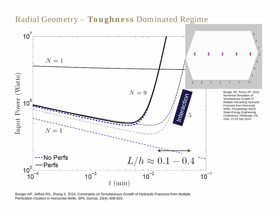
Radial Geometry – Toughness Dominated Regime
Bunger AP, Peirce AP. 2014. Numerical Simulation of Simultaneous Growth of Multiple Interacting Hydraulic Fractures from Horizontal Wells. Proceedings ASCE Shale Energy Engineering Conference, Pittsburgh, PA, USA, 21-23 July 2014.
Bunger AP, Jeffrey RG, Zhang X. 2014. Constraints on Simultaneous Growth of Hydraulic Fractures from Multiple Perforation Clusters in Horizontal Wells. SPE Journal, 19(4): 608-620.

PKN Geometry – Viscosity Dominated Regime

Minimum power is associated with an INTERMEDIATEnumber of HFs
PKN Geometry – Viscosity Dominated Regime

Global min – but can’t get there
Expect h~1.2-2 H
Perforation diameter
PKN “Linguine” Case – Energetically Preferred Spacing

Stress shadow –
pushes apart
Min viscous dissipation –
brings together
Predicted Emergent
spacing
Natural spacing ->energy minimum resulting from combination of stress shadow and viscous dissipation

Early Successes – Example from Barnett ShaleFisher et al. 2004, SPE 90051
“…regularly spaced cross-cutting fractures that tend to appear at roughly 500 ft intervals regardless of perforation cluster location.”
H~350 ft h~1.4 H

– Mean distal spacing in 1270 Ma Mackenzie (<h>~27 km) Swarm, Ontario, Canada in range of estimated H~20-40 km
– Krafla rifting episode, Iceland, <H>~2.8 km
– Tertiary Alftafjördur dyke swarm, Iceland, <h>~2.5 km
– Next steps:
– Earth in greater detail
– Contrast Earth, Mars, Venus
Bunger AP, Menand T, Cruden AR, Zhang X, Halls H. 2013. Analytical predictions for a natural spacing within dyke swarms. Earth and Planetary Science Letters, 375:270-279.

Approximate with plane strain model?
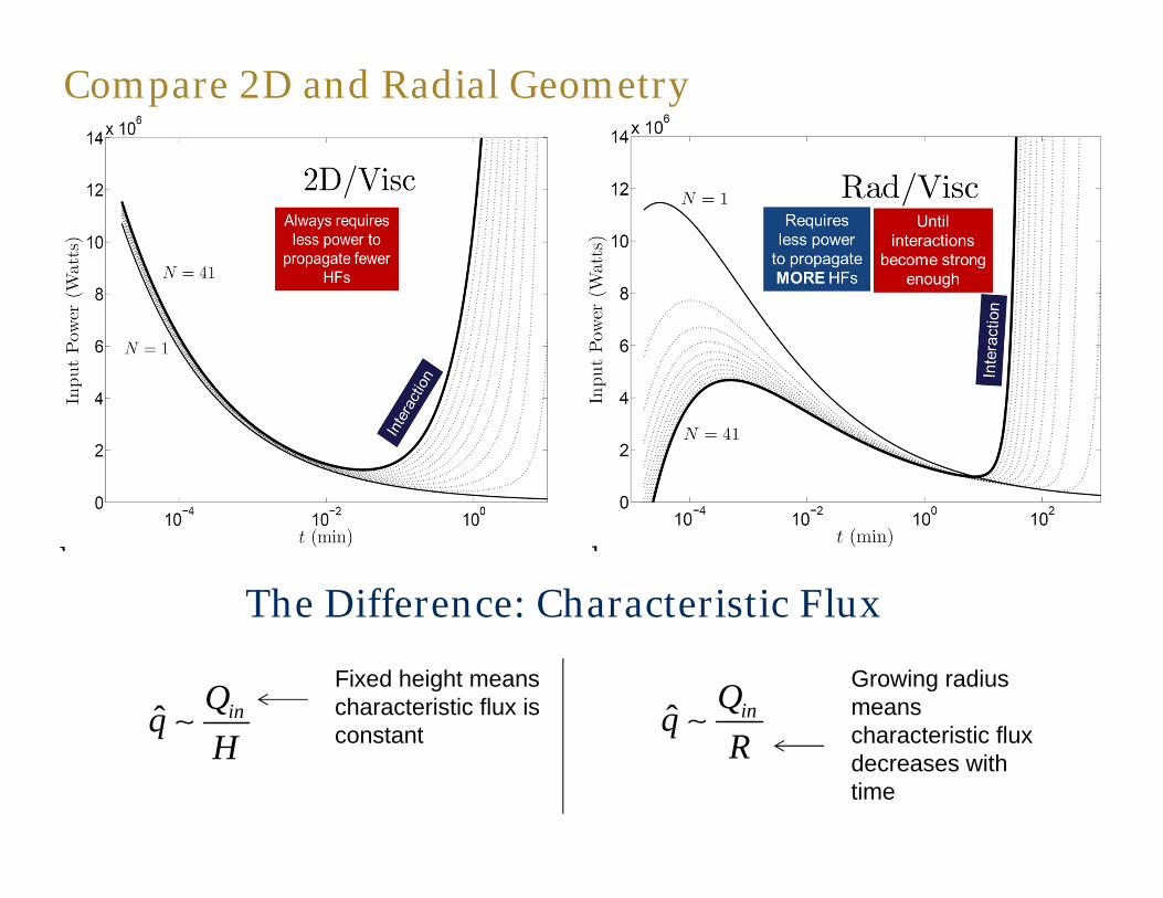
Compare 2D and Radial Geometry
ˆ inqHQ ˆ inq
RQ
The Difference: Characteristic Flux
Fixed height means characteristic flux is constant
Growing radius means characteristic flux decreases with time

Compare 2D and Blade-Like Geometry
W PLE W PH
E
The Difference: From Elasticity
Growing length means crack compliance decreases with time
Fixed height means crack compliance is constant
PKN/Visc

Maxwell et al. 2002, SPE 77400
Spacing of lineaments: 300 ft

Approximate with plane strain model?
2D model much more prone to localization
Approximate with uncoupled model (fracture mechanics only)?

Compare Viscosity and Toughness
IcKPR
3inP
WQ
The Difference: Characteristic Pressure
Pressure scale from LEFM propagation condition
Pressure scale from Poiseuillefluid flow equation

Approximate with plane strain model?
2D model much more prone to localization
Approximate with uncoupled model (fracture mechanics only)?
Misses the main driving physical mechanism – and again gives a prediction that is much more prone to localization

Conclusions
• Predictions of swarm-like multiple HF growth versus localization are profoundly different for different geometries and propagation regimes
• Toughness dominated and/or 2D HFs are not expected to exhibit swarm-like growth (in absence of perforation losses)
• Radial, viscosity-dominated HFs favor multiple growth until the radius attains a similar value to the spacing
• Blade-shaped, viscosity-dominated HFs swarm with a characteristic spacing coming from fracture height H
Note: Applications now are aimed at forcing spacing to be less than H.

33
C2Frac – Energy and Asympotics-Based Simulator
C Cheng and A P Bunger, In Review ~1 sec ~1 week
- Penny-shaped crack solution- Far field approx of interaction- Update pressure using global
energy balance

34Good match until R~0.6Z

35

36

37
• An additional N equation is obtained from the interaction stresses. The main challenge and focus of the problem is due to interaction and the impact of the interaction on hydraulic fracture growth, including the effect on the partitioning of the fluid embodied by Qi.
where , By letting be the mean injection rate to the jthhydraulic fracture and and , where Rj is the radius of the jth hydraulic fracture and hi,j is the separation between the jth and the ith hydraulic fracture; we can approximate the interaction stresses exerted on the ith hydraulic fracture as
)(25
1091;, 42
23
'
Oh
tQEQ i
iI
Rh / jQ
jji,ij Rh / jj Rr /
,
i ,j 1
ˆ , , ;N j i
I j i j jr t Q

38
• However, the interaction stresses remain uncoupled from the other 4N equations. The proposed solution for this issue, which is the critical component of the C2Frac algorithm, is to replace the estimate of the pressure, with an updated estimate that obtains its correction via an energy balance equation for each hydraulic fracture of the form derived by Bunger(IJSS, 2013). This energy balance is given by
• : increases the elastic strain energy stored in the rock
• : overcome the negative work being created on each hydraulic fracture by the stress interactions from its neighbors
• Dc: breaking the rock (assume equals zero)
• Df: viscous fluid flow
• σmin: is constant at uniform reservoir condition
fcIfii DDWUtpQ ..
min,0
IW
U

Epilogue: Promoting multiple fracture initiation and growth
Peirce AP, Bunger AP. Interference Fracturing: Non-Uniform Distributions of Perforation Clusters that Promote Simultaneous Growth of Multiple Hydraulic Fractures. SPE Journal, In Press. Pre-print: http://hdl.handle.net/2429/45492