challenges and opportunities for structural health ... … · chall enges and opportunities for...
TRANSCRIPT
CHALLENGES AND OPPORTUNITIES FOR STRUCTURAL HEALTH MONITORING IN PVP APPLICATIONS
Victor Giurgiutiu, PhD
University of South Carolina Columbia, SC 29208, USA
ABSTRACT This paper discusses the challenges and opportunities of using structural health monitoring (SHM) concepts and technologies in pressure vessels and piping (PVP) applications. The research into monitoring of structural health has experienced a dramatic increase in the last decade due to at least two factors. On the one hand, our industrial installations, aircraft fleets, civil infrastructure, etc. are becoming increasingly aged and require more and more maintenance costly actions and repairs. This process could be greatly improved if scheduled maintenance were augmented or even replaced by continuous monitoring that would limit costly inspections and maintenance actions to being done only when needed; and (b) the advent of advanced technologies, e.g., active materials based sensors, actuators, and transducers as well as advanced data acquisition, data processing, and data mining technologies that enable the practical implementation of the SHM concepts. To date, the SHM research has been mainly performed for the aerospace, defense, and civil infrastructure applications and some interesting proof-of-concept results have been demonstrated. Very little research, if at all, has been done on using the SHM concepts in PVP applications. The reason for this situation may be that PVP applications may be more challenging than the other applications in which SHM concepts have been tried so far. The present paper explores this topic and highlight (a) the challenges that have to be overcome in order to develop SHM for PVP applications; and (b) the opportunities that exist for using SHM in PVP applications. The paper starts with a review of the main SHM concepts and technologies. Then, the paper identifies the challenges that would exist if these SHM concepts and technologies were to be applied the PVP applications. Finally, the paper discusses the opportunities for applying SHM to PVP applications forward. The paper ends with conclusions and suggestions for further work.
INTRODUCTION Many pressure vessel and piping (PVP) systems are safety-critical facilities in need of monitoring over prolonged periods of time. Structural health monitoring (SHM) is an emerging technology that aims at monitoring the state of a structure through the use of networks of permanently mounted sensors. SHM technologies have been developed primarily within the aerospace and civil engineering communities. However, SHM concepts and methodologies could be extended to other safety-critical systems. Many PVP applications, as for example, nuclear power plants (NPP) are safety-critical facilities in need of monitoring over prolonged periods of time. One of the key aspects of improving the reliability, sustaining the safety, and extending the life of current PVP is to develop technologies that can better diagnose their state of structural health. NDE material condition monitoring and SHM systems must be integrated to quantify the “state of health” of the PVP systems and structures. Monitoring these aging structures with minimum human intervention would be of paramount importance and great benefit. In addition, such tools can provide invaluable and timely information for verification of the predicted mechanical performance of critical PVP applications during off-normal occurrence and accident events such as the tsunami and earthquake event that affected Fukushima Daiichi nuclear power plant [1]. One possible way to assess the current condition of structures, and, more importantly, to predict the residual safe operating life of PVP systems is to develop new sensing techniques that monitor the integrity of PVP components. Guided wave SHM technologies have a wide range of applications based on both propagating-wave and standing-wave methodologies. Hence, opportunities exist for
Proceedings of the ASME 2014 Pressure Vessels & Piping Conference PVP2014
July 20-24, 2014, Anaheim, California, USA
PVP2014-28010
1 Copyright © 2014 by ASME
transitioning these SHM technologies into PVP monitoring applications. By implementing “embedded” nondestructive sensors, SHM can enhance the inspectability of PVP systems. This will allow real-time assessment of the structural conditions and prediction of service life with greater reliability. However, certain special operational conditions exist that are specific to PVP applications such as: aggressive environments, marine environments, radiation fields, and chemical, mechanical and thermal stressors. This will require research to develop monitoring, diagnosis, and prognosis tools that can aid to establish a strong technical basis for the safety of PVP systems. This paper addresses the issue of transitioning the SHM concept to the monitoring of PVP applications and evaluates the opportunities and challenges associated with this process. Our focus is mainly of PVP applications in the nuclear power plants (NPP). This paper discusses some of the challenges associated with the verification and diagnosis of PVP systems and identifies SHM technologies which are more readily available for transitioning into PVP applications. Fundamental research objectives that should be considered for the transition of SHM technologies (e.g., radiation hardened piezoelectric materials with high-temperature capabilities) to PVP applications are discussed.
NUCLEAR POWER PLANT SAFETY ASSESSMENT
The state of the art of nuclear power plant safety assessment methodology was comprehensively presented in ref. [2]. Here, we will recall some of the main issues highlighted in this excellent work [2]. All US nuclear power plants (NPP) are designed, built, and operated using a defense-in-depth strategy for maintaining safety and high reliability [3]. No single action, system, or component is dependent upon for safety; instead, the defense-in-depth approach relies on a number of actions, systems, and components with multiple backups to achieve a multi-layer defense strategy. The defense-in-depth strategy is applied throughout all the stages in a NPP life cycle:
• design stage • construction stage (fabrication and assembly) • pre-service testing • in-service inspection (ISI) • post-service evaluation
In the design stage, all efforts are made to assure that the NPP will maintain structural integrity and leak-tight integrity of all components that are important to safety, under all known loading conditions and over the expected NPP operating life. Anticipated and unanticipated operating conditions as well as postulated accident scenarios are considered. Multiple failure modes are considered and the structure is designed to sustain its integrity even after partial degradation to allow for timely in-service detection. The best available materials are selected based on their high strength, toughness, and corrosion resistance. Extraordinary efforts are made to prevent or
minimize accidents and to mitigate the effect of accidents should they occur. In the construction stage, the fabrication and assembly is done with the best possible workmanship. The welding process, in particular, is subject to high scrutiny. The whole construction stage is highly regulated by NRC 10 CFR [4] which refers for technical details to the ASME Boiler and Pressure Vessel (BPV) Code [5]. Nondestructive evaluation (NDE) plays a major role in the implementation of the ASME BPV Code which sets standards for workmanship to be met through accept/reject criteria based on NDE measurements. The pre-service testing stage is a comprehensive process in which the new NPP is subjected to a complex of operational and safety tests that lead to the new NPP being fully commissioned and declared safe for service. The in-service inspection (ISI) stage is a sustained process that is applied throughout the NPP service life. NDE plays a crucial role during the in-service inspection process because it is charged with detecting the ‘unexpected’, i.e., the conditions and phenomena that were not anticipated/considered during the design phase and in the selection of materials and fabrication methods. The post-service evaluation is performed on decommissioned NPPs in order to assess the capability of NDE processes to identify and characterize construction flaws that were then validated through destructive testing.
The NDE Process The NDE processes applied during ISI are covered by Section XI of the ASME BPV Code [5]. As indicated in ref. [2], the dominant NDE method for ISI is ultrasonic testing (UT). Although UT is effective and wide spread in its use, it has several shortcomings such as (a) variability of detection results as function of testing and operator conditions; (b) preponderance in detecting certain damage types (e.g., fatigue cracks); etc. A multi-year program was conducted at the Pacific Northwest National Laboratory (PNNL) to assess and improve NDE reliability through its integration with fracture mechanics methodology [2]. A number of round-robin tests were performed and probability of detection (POD) curves were determined for various testing and operator conditions. According to ref. [2], the most important conclusion drawn from these studies is that ‘NDE is very skill-dependent; the only way to ensure that examinations are conducted to high standards is to develop and implement a performance demonstration process for personnel, equipment, and procedures.’ The performance demonstration process would provide national uniformity. A statistically-based design must be used for blind performance demonstration testing to achieve useful quantification of inspection performance. Real configurations should be used and the flaws representative of degradation important to structural integrity should be detected reliably. Only combinations of personnel/equipment/procedures that successfully pass the performance demonstration test would be allowed to conduct UT for the ISI of NPPs. The performance demonstration was designed as a screening test. It
2 Copyright © 2014 by ASME
was not intended to quantify the POD curve for each inspector, because this would be cost and time prohibitively expensive. Instead, a statistically based sampling process was developed; it was possible to collapse the performance demonstration data across inspectors that are using the same procedure.
Issues and Challenges in the NDE ISI of NPP Ref. [2] identifies several issues and challenges related to the use of UT NDE for ISI of NPP. The amplitude-based prescriptive requirements of the ASME BPV Code used for UT NDE during ISIs works well for highly responsive mechanical fatigue flaws that grow perpendicular to the component surface, are not under compressive stresses, and are planar. However, the degradation mechanism appearing in current NPPs do not behave in this manner. Straight forward fatigue cracks rarely appear in NPPs which were designed to high standards that took into consideration the prevention of fatigue degradation. The failures observed in current NPPs are much more complicated. For example, ‘the occurrence of intergranular stress corrosion cracking (IGSCC) in stainless steel piping of boiling water reactors led to tight branched cracks that propagate along the hear-affected zone of welds.’ Thus, a combination of two adverse conditions make the UT detection very difficult: the cracks are diffused and remnant compressive stresses keep the cracks shut. Another example is that of cast austenitic stainless steel (CASS) used in cast austenitic piping welds. While this material has performed reliably in service, it is susceptible to thermal fatigue. The industry has not yet qualified a reliable method for its inspection and conventional UT methods give about 20% detection. Current studies involving eddy current testing (ET) and low frequency (0.5 MHz) UT phased arrays show have demonstrated great improvements though. In aging NPPs, degradation that was not an issue during the initial years of operation may become an important process in later operation. A number of new degradation processes have been found (on average, a new one every 7 years), but most are not fatigue related [2]. For example the cracks that appeared in the primary water main loop piping at VC Summer and control rod drive mechanism at Oconee were due to primary water stress corrosion cracking. New degradation mechanisms are expected to appear and the challenge is: could NDE detect them before failure occurs?
NDE Research Needs So far, NDE has been reactive rather than proactive w.r.t. new degradation mechanisms. All new degradation processes have almost always been found through leakage from components rather than ISI [2]. After the degradation process is discovered, the NDE procedures are refined in order to detect it. However, the goal is to manage degradation, detect the unexpected, and prevent failure. Hence, a material degradation management program is needed to give NDE a proactive stance. Several improvements to the existing NDE/ISI programs have been proposed [2]:
• shortening the inspection intervals where appropriate
• improving the reliable detection of smaller flaws • using continuous online monitoring where degradation
growth rate is high or where the access is limited • increasing the number of inspected components
However, for the long run, a sustained NDE research effort is needed. Models should be developed for all the NDE methods employed in nuclear power plants [2]. These models could provide a basis for assessing the effectiveness of degradation processes that have not occurred by might be expected. They would provide a basis for the expansion of performance demonstration to other components and to other NDE methods. Development of NDE techniques to perform in-situ measurement of material properties and degradation process would be of great use in preventing degradation failures. Many factors are of interest: residual stresses, mechanical properties, chemistry in localized zones. Requirements should also be in place to determine these properties during construction and thus form a baseline for monitoring [2].
STRUCTURAL HEALTH MONITORING (SHM)
Structural health monitoring (SHM) assesses the state of structural health and, through appropriate data processing and interpretation, may predict the remaining life of the structure [6]. Structural health is a major concern of the engineering community and SHM is especially important for detection and monitoring of structure degradation such as crack growth under fatigue loading and/or due to environmental degradation conditions, such as corrosion due to marine environment. SHM methods can be passive or active: passive SHM infers the state of structural health from measuring various operational parameters. For example, one could monitor the flight parameters of an aircraft (airspeed, air turbulence, g–factors, vibration levels, stresses in critical locations, etc.) and then use the aircraft design algorithms to infer how much of aircraft’s useful life has been used up and how much remains. Passive SHM is useful, but it does not directly address the crux of the problem, i.e., it does not directly examine if the structure has been damaged or not. Active SHM is concerned with directly assessing the state of structural health by detecting the presence and extent of structural damage. In this respect, the active SHM approach is similar to the approach taken by ultrasonic NDE, only that active SHM takes it one step further: active SHM uses damage detection sensors that can be permanently installed on the structure and its monitoring methods can provide on demand a structural health bulletin. The active SHM methods use smart sensors that can send and receive elastic waves in the structure. Thus, they can perform damage detection on demand. SHM can be an essential tool to monitor important to safety (ITS) structures and assess the health of structures after an off-normal occurrence or natural accident event.
PIEZOELECTRIC WAFER ACTIVE SENSORS (PWAS)
One type of smart sensor for active SHM is the piezoelectric wafer active sensor (PWAS). The PWAS transducers can be
3 Copyright © 2014 by ASME
permanently attached to a structure and left in place during operation while still being small, inexpensive, unobtrusive, and
reliable [7][8][9][10].
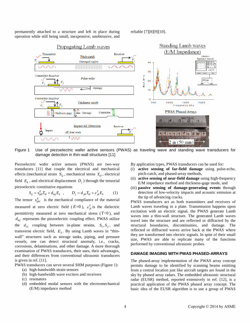
Figure 1 Use of piezoelectric wafer active sensors (PWAS) as traveling wave and standing wave transducers for
damage detection in thin-wall structures [11]
Piezoelectric wafer active sensors (PWAS) are two-way transducers [11] that couple the electrical and mechanical effects (mechanical strain ijS , mechanical stress klT , electrical field kE , and electrical displacement jD ) through the tensorial piezoelectric constitutive equations ,E T
ij ijkl kl kij k j jkl kl jk kS s T d E D d T Eε= + = + (1)
The tensor Eijkls is the mechanical compliance of the material
measured at zero electric field ( =0E ), Tjkε is the dielectric
permittivity measured at zero mechanical stress ( =0T ), and kijd represents the piezoelectric coupling effect. PWAS utilize
the 31d coupling between in-plane strains, 1 2,S S , and transverse electric field, 3E . By using Lamb waves in “thin-wall” structures such as storage tanks, piping, and pressure vessels, one can detect structural anomaly, i.e., cracks, corrosions, delaminations, and other damage. A more thorough examination of PWAS transducers, their uses, their advantages, and their differences from conventional ultrasonic transducers is given in ref. [11]. PWAS transducers can serve several SHM purposes (Figure 1):
(a) high-bandwidth strain sensors (b) high-bandwidth wave exciters and receivers (c) resonators (d) embedded modal sensors with the electromechanical
(E/M) impedance method
By application types, PWAS transducers can be used for: (i) active sensing of far-field damage using pulse-echo,
pitch-catch, and phased-array methods, (ii) active sensing of near-field damage using high-frequency
E/M impedance method and thickness-gage mode, and (iii) passive sensing of damage-generating events through
detection of low-velocity impacts and acoustic emission at the tip of advancing cracks.
PWAS transducers act as both transmitters and receivers of Lamb waves traveling in a plate. Transmission happens upon excitation with an electric signal, the PWAS generate Lamb waves into a thin-wall structure. The generated Lamb waves travel into the structure and are reflected or diffracted by the structural boundaries, discontinuities, and damage. The reflected or diffracted waves arrive back at the PWAS where they are transformed into electric signals. In spite of their small size, PWAS are able to replicate many of the functions performed by conventional ultrasonic probes.
DAMAGE IMAGING WITH PWAS PHASED-ARRAYS
The phased-array implementation of the PWAS array concept permits damage to be identified by scanning beams emitting from a central location just like aircraft targets are found in the sky by phased array radars. The embedded ultrasonic structural radar (EUSR) method, reported extensively in ref. [12], is a practical application of the PWAS phased array concept. The basic idea of the EUSR algorithm is to use a group of PWAS
4 Copyright © 2014 by ASME

arranged in a particular pattern and manipulate the synthetic output beam at a particular direction by adjusting the delays between the firing of each element. Among the possible array configurations, the linear array obtained by arranging elements
along a straight line presents is the simplest one, as illustrated in Figure 2a.
(a) (b) Figure 2 Schematic of experimental setup for fatigue testing with PWAS: (a) schematic of specimen #2 showing the
installation of the PWAS array and the location of the precrack; (b) instrumentation schematics [13]
The phased-array concept was used on a 600-mm by 700-mm panel of 1-mm 2024-T3 aluminum alloy instrumented with a 10-PWAS phased array placed at its center (Figure 2b) [13]. The instrumentation consisted of an HP 33120 signal generator, a TDS210 digital oscilloscope, an ASCU auto-switch unit, and a laptop computer (Figure 2a). Round-robin data collection was performed in the following way: a 3-count 372 kHz tone-burst excitation signal was synthesized in the function generator at a frequency corresponding to the optimum tuning of the PWAS with the S0 Lamb-wave mode in the plate. The tone-burst signal is sent to one PWAS in the array, travels into the plate, and is reflected at the crack and later at the plate boundary. The reflected Lamb-waves packet is received back at all the elements of the PWAS array. The signals received at each PWAS in the array (including the transmitting PWAS) and collected by the DAQ device, i.e., the digital oscilloscope generate a column of 10 elemental signals in a 100 elemental-signals array. This procedure is repeated for all the PWAS [13]. The EUSR algorithm software processes the measured PWAS phased array data and produces an image of the scanning results. Figure 3a shows the EUSR front panel. The threshold value, the values δ, and θ of the “dial angles” were controlled from the panel (Figure 3b). First, an approximate position of the crack edge is obtained with the azimuth dial. If
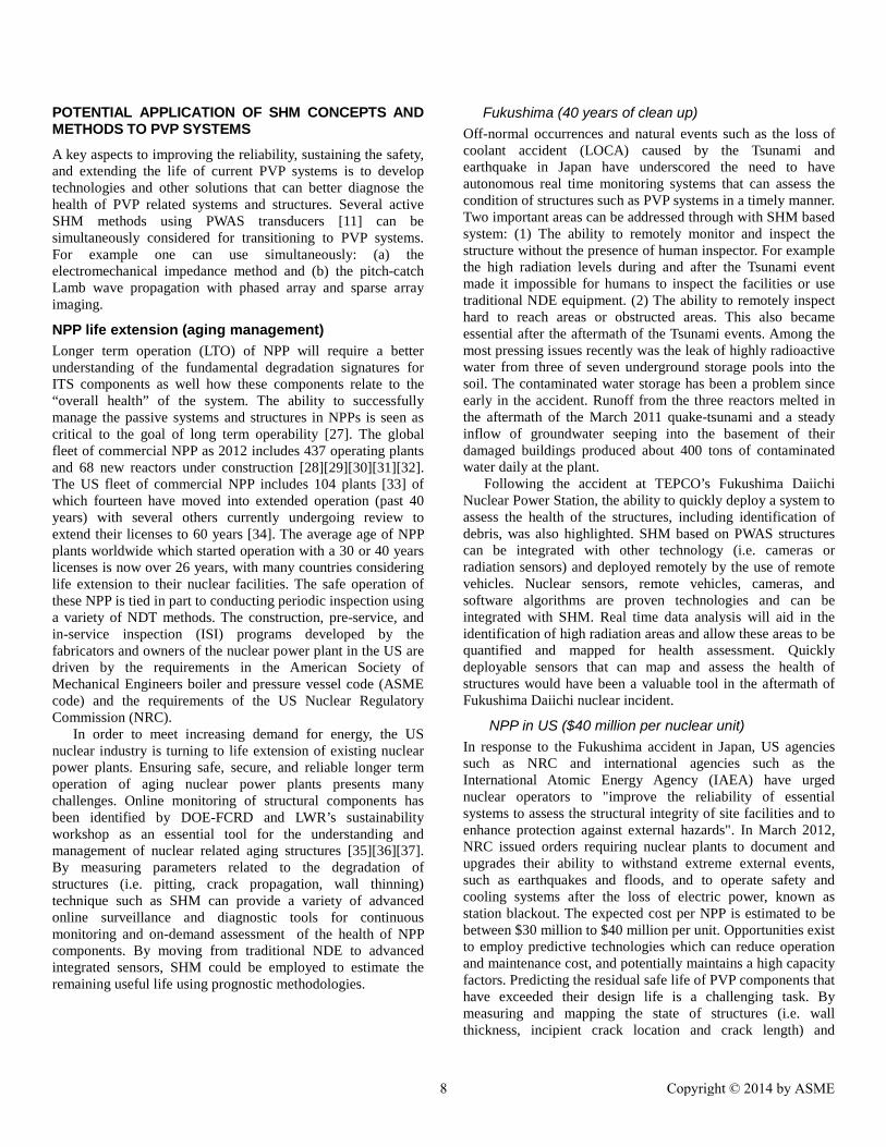
the azimuth dial is turned to an angle where the synthetic beam find a target and gets a reflection, then the A-scan image will show a reflection echo as illustrated in Figure 3a. After a threshold value was chosen, the θ and δ angles were adjusted such that their rays touched the left and right tips (respectively) of the crack image reproduced in the EUSR GUI. The EUSR image was then used to obtain an estimation of the crack size. To verify the PWAS phased array detection capability under operational loads, the specimen was subjected to high-load fatigue loading of maxF = 17,800 N (4000 lbf) and minF = 1,780 N (400 lbf), i.e., R = 0.1. The precrack size was 2a = 25 mm; the corresponding stress intensity factor at the beginning of the test was 5.8 MPa mK∆ ≅ . During fatigue testing, the crack in the panel grew from 25 mm to beyond 60 mm. Figure 4 shows a progression of cracks sizes, as they developed in specimen during the fatigue testing. The upper row of the images in Figure 4 displays the optical photos taken with a digital camera. The lower row of images in Figure 4 shows the PWAS phased-array images of the same crack obtained with the EUSR method. Good correspondence exists between the two rows of images in terms crack length versus cycle count.
Crack
PWAS Array
5 Copyright © 2014 by ASME
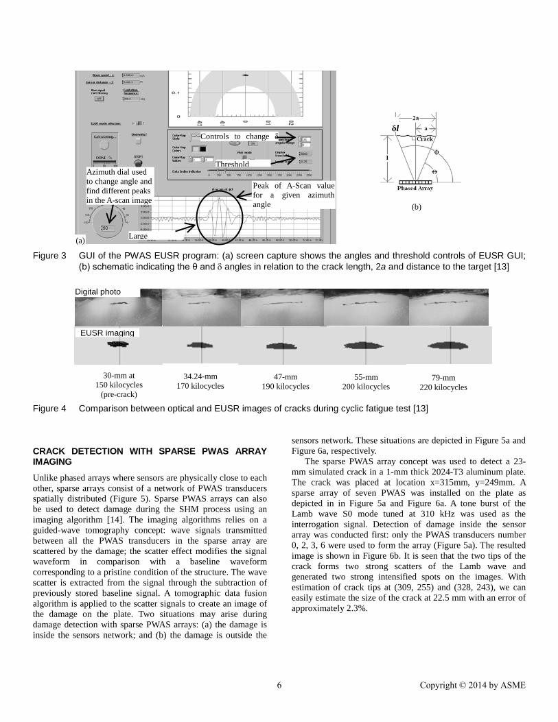
Figure 3 GUI of the PWAS EUSR program: (a) screen capture shows the angles and threshold controls of EUSR GUI;
(b) schematic indicating the θ and δ angles in relation to the crack length, 2a and distance to the target [13]
Figure 4 Comparison between optical and EUSR images of cracks during cyclic fatigue test [13]
CRACK DETECTION WITH SPARSE PWAS ARRAY IMAGING
Unlike phased arrays where sensors are physically close to each other, sparse arrays consist of a network of PWAS transducers spatially distributed (Figure 5). Sparse PWAS arrays can also be used to detect damage during the SHM process using an imaging algorithm [14]. The imaging algorithms relies on a guided-wave tomography concept: wave signals transmitted between all the PWAS transducers in the sparse array are scattered by the damage; the scatter effect modifies the signal waveform in comparison with a baseline waveform corresponding to a pristine condition of the structure. The wave scatter is extracted from the signal through the subtraction of previously stored baseline signal. A tomographic data fusion algorithm is applied to the scatter signals to create an image of the damage on the plate. Two situations may arise during damage detection with sparse PWAS arrays: (a) the damage is inside the sensors network; and (b) the damage is outside the
sensors network. These situations are depicted in Figure 5a and Figure 6a, respectively. The sparse PWAS array concept was used to detect a 23-mm simulated crack in a 1-mm thick 2024-T3 aluminum plate. The crack was placed at location x=315mm, y=249mm. A sparse array of seven PWAS was installed on the plate as depicted in in Figure 5a and Figure 6a. A tone burst of the Lamb wave S0 mode tuned at 310 kHz was used as the interrogation signal. Detection of damage inside the sensor array was conducted first: only the PWAS transducers number 0, 2, 3, 6 were used to form the array (Figure 5a). The resulted image is shown in Figure 6b. It is seen that the two tips of the crack forms two strong scatters of the Lamb wave and generated two strong intensified spots on the images. With estimation of crack tips at (309, 255) and (328, 243), we can easily estimate the size of the crack at 22.5 mm with an error of approximately 2.3%.
Azimuth dial used to change angle and find different peaks in the A-scan image
Threshold
Large
Controls to change δ
δl
(b)
(a)
Peak of A-Scan value for a given azimuth angle
30-mm at 150 kilocycles
(pre-crack)
34.24-mm 170 kilocycles
47-mm 190 kilocycles
55-mm 200 kilocycles
Digital photo
EUSR imaging
79-mm 220 kilocycles
6 Copyright © 2014 by ASME

Figure 5 PWAS focusing array imaging for the damage inside the PWAS sparse array [14]
Figure 6 PWAS focusing array imaging for the damage outside the PWAS sparse array [14]
Figure 6 presents the case when the damage is NOT inside the sparse array, i.e., when transducers number 2, 4, 5, 6 were used to form the array. It is apparent from Figure 6a that the crack is placed outside the sparse array. Imaging results are given in Figure 6b indicating clear and correct location of the 23-mm simulated crack even though it location was outside the sparse array. However, the size of the crack could not be easily determined in this situation when the damage was outside the sparse array. It is apparent from these results that the sparse array method may provide good damage detection and quantification. The limitation of the method is the need for a baseline reading, which was not necessary in the case of the phased-array scanning beam approach.
Current status of SHM usage SHM has been intensively investigated by various research groups. An overview of the state of the art of PWAS SHM technology was given in ref. [6], [11]. SHM have been investigated for the aerospace industry including National Aeronautics and Space Administration (NASA), civilian
transportation, DOD, DOE, etc.. The place of SHM in the flight structures fundamental research trends and directions was discussed in ref. [15]. The use of the electromechanical impedance technique [16] for SHM of engineering structures has been reviewed in ref. [17]. Vibration based SHM was reviewed in ref. [9], [18]. The connection between SHM and NDE was highlighted in ref.[19]. A comprehensive review of guided-wave SHM was presented in ref. [20]. A conceptual description of combining vibration and wave propagation SHM methods was discussed in ref. [21]. SHM technology has also been applied to civil engineering structures such as bridges [22][23]. Other civil engineering uses of SHM include monitoring of disbond detection in concrete structures strengthened with FRP composite overlays [24], vibration based detection of a fluid filled tank [25]. Active SHM finds is usefulness in green energy systems such as wind farms [26]
(a) (b)
(a) (b)
7 Copyright © 2014 by ASME
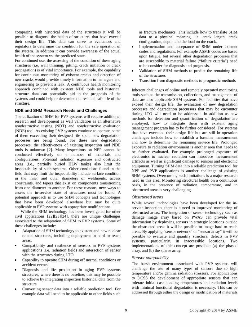
POTENTIAL APPLICATION OF SHM CONCEPTS AND METHODS TO PVP SYSTEMS
A key aspects to improving the reliability, sustaining the safety, and extending the life of current PVP systems is to develop technologies and other solutions that can better diagnose the health of PVP related systems and structures. Several active SHM methods using PWAS transducers [11] can be simultaneously considered for transitioning to PVP systems. For example one can use simultaneously: (a) the electromechanical impedance method and (b) the pitch-catch Lamb wave propagation with phased array and sparse array imaging.
NPP life extension (aging management) Longer term operation (LTO) of NPP will require a better understanding of the fundamental degradation signatures for ITS components as well how these components relate to the “overall health” of the system. The ability to successfully manage the passive systems and structures in NPPs is seen as critical to the goal of long term operability [27]. The global fleet of commercial NPP as 2012 includes 437 operating plants and 68 new reactors under construction [28][29][30][31][32]. The US fleet of commercial NPP includes 104 plants [33] of which fourteen have moved into extended operation (past 40 years) with several others currently undergoing review to extend their licenses to 60 years [34]. The average age of NPP plants worldwide which started operation with a 30 or 40 years licenses is now over 26 years, with many countries considering life extension to their nuclear facilities. The safe operation of these NPP is tied in part to conducting periodic inspection using a variety of NDT methods. The construction, pre-service, and in-service inspection (ISI) programs developed by the fabricators and owners of the nuclear power plant in the US are driven by the requirements in the American Society of Mechanical Engineers boiler and pressure vessel code (ASME code) and the requirements of the US Nuclear Regulatory Commission (NRC). In order to meet increasing demand for energy, the US nuclear industry is turning to life extension of existing nuclear power plants. Ensuring safe, secure, and reliable longer term operation of aging nuclear power plants presents many challenges. Online monitoring of structural components has been identified by DOE-FCRD and LWR’s sustainability workshop as an essential tool for the understanding and management of nuclear related aging structures [35][36][37]. By measuring parameters related to the degradation of structures (i.e. pitting, crack propagation, wall thinning) technique such as SHM can provide a variety of advanced online surveillance and diagnostic tools for continuous monitoring and on-demand assessment of the health of NPP components. By moving from traditional NDE to advanced integrated sensors, SHM could be employed to estimate the remaining useful life using prognostic methodologies.
Fukushima (40 years of clean up) Off-normal occurrences and natural events such as the loss of coolant accident (LOCA) caused by the Tsunami and earthquake in Japan have underscored the need to have autonomous real time monitoring systems that can assess the condition of structures such as PVP systems in a timely manner. Two important areas can be addressed through with SHM based system: (1) The ability to remotely monitor and inspect the structure without the presence of human inspector. For example the high radiation levels during and after the Tsunami event made it impossible for humans to inspect the facilities or use traditional NDE equipment. (2) The ability to remotely inspect hard to reach areas or obstructed areas. This also became essential after the aftermath of the Tsunami events. Among the most pressing issues recently was the leak of highly radioactive water from three of seven underground storage pools into the soil. The contaminated water storage has been a problem since early in the accident. Runoff from the three reactors melted in the aftermath of the March 2011 quake-tsunami and a steady inflow of groundwater seeping into the basement of their damaged buildings produced about 400 tons of contaminated water daily at the plant. Following the accident at TEPCO’s Fukushima Daiichi Nuclear Power Station, the ability to quickly deploy a system to assess the health of the structures, including identification of debris, was also highlighted. SHM based on PWAS structures can be integrated with other technology (i.e. cameras or radiation sensors) and deployed remotely by the use of remote vehicles. Nuclear sensors, remote vehicles, cameras, and software algorithms are proven technologies and can be integrated with SHM. Real time data analysis will aid in the identification of high radiation areas and allow these areas to be quantified and mapped for health assessment. Quickly deployable sensors that can map and assess the health of structures would have been a valuable tool in the aftermath of Fukushima Daiichi nuclear incident.
NPP in US ($40 million per nuclear unit) In response to the Fukushima accident in Japan, US agencies such as NRC and international agencies such as the International Atomic Energy Agency (IAEA) have urged nuclear operators to "improve the reliability of essential systems to assess the structural integrity of site facilities and to enhance protection against external hazards". In March 2012, NRC issued orders requiring nuclear plants to document and upgrades their ability to withstand extreme external events, such as earthquakes and floods, and to operate safety and cooling systems after the loss of electric power, known as station blackout. The expected cost per NPP is estimated to be between $30 million to $40 million per unit. Opportunities exist to employ predictive technologies which can reduce operation and maintenance cost, and potentially maintains a high capacity factors. Predicting the residual safe life of PVP components that have exceeded their design life is a challenging task. By measuring and mapping the state of structures (i.e. wall thickness, incipient crack location and crack length) and
8 Copyright © 2014 by ASME
comparing with historical data of the structures it will be possible to diagnose the health of structures that have exceed their design life. This data can serve to evaluators and regulators to determine the condition for the safe operation of the system. In addition it can provide awareness of the actual health of the system vs. the predicted state. For continued use, the assessing of the condition of these aging structures (i.e. wall thinning, pitting, crack initiation or crack propagation) is of vital importance. For example, the capability for continuous monitoring of existent cracks and detection of new cracks would provide timely information to managers and engineering to prevent a leak. A continuous health monitoring approach combined with existent NDE tools and historical structure data can potentially aid in the prognosis of the systems and could help to determine the residual safe life of the structure.
NDE and SHM Research Needs and Challenges The utilization of SHM for PVP systems will require additional research and development as well validation as an alternative nondestructive testing (NDT) and nondestructive evaluation (NDE) tool. As existing PVP systems continue to operate, some of them exceeding their designed life span, new degradation processes are being found. For these new degradation processes, the effectiveness of existing inspection and NDE tools is unknown [2]. Many inspections on NPP cannot be conducted effectively on a number of materials and configurations. Potential radiation exposure and obstructed areas (i.e., partially buried HLW tanks) also limit the inspectability of such systems. Other conditions found in the field that may limit the inspectability include surface condition in the inner and outer diameters of weldments, access constraints, and tapers that exist on components transitioning from one diameter to another. For these reasons, new ways to assess the in-service state of structures must be found. A potential approach is to use SHM concepts and technologies that have been developed elsewhere but may be quite applicable to PVP systems with appropriate modifications. While the SHM technology has been investigated for other civil applications [22][23][24], there are unique challenges associated to the adaptation of SHM to PVP systems. Some of these challenges include: • Adaptation of SHM technology to existent and new nuclear
related structures, including deployment in hard to reach areas.
• Compatibility and resilience of sensors in PVP systems applications (i.e. radiation field) and interaction of sensor with the structures during LTO.
• Capability to operate SHM during off normal conditions or accident events.
• Diagnosis and life prediction in aging PVP systems structures, where there is no baseline; this may be possible to achieve by integrating inspection historical data from the structure
• Converting sensor data into a reliable prediction tool. For example data will need to be applicable to other fields such
as fracture mechanics. This include how to translate SHM data to a physical meaning, i.e. crack length, crack configuration, depth, and the load on the crack.
• Implementation and acceptance of SHM under existent codes and regulations. For example ASME codes are based upon fatigue, but several other degradation processes that are susceptible to material failure (“failure criteria”) need to be consider for diagnosis and prognosis.
• Validation of SHM methods to predict the remaining life of the structures
• Transition from diagnostic methods to prognostic methods Inherent challenges of online and remotely operated monitoring tools such as the transmission, collections, and management of data are also applicable SHM systems. For facilities that have exceed their design life, the evaluation of new degradation processes and degradation precursors that may be encounter during LTO will need to be addressed. In addition as new methods for detection and quantification of degradation are employed, how to integrate them with existent aging management program has to be further considered. For systems that have exceeded their design life but are still in operation challenges include how to establish a baseline measurement and how to determine the remaining service life. Prolonged exposure to radiation environment is another area that needs to be further evaluated. For example prolonged exposure of electronics to nuclear radiation can introduce measurement artifacts as well as significant damage to sensors and electronic equipment. Turning SHM data into a reliable prediction tool for NPP and PVP applications is another challenge of existing SHM systems. Overcoming such limitations is a major research need in this area. Monitoring structural health on a continuous basis, in the presence of radiation, temperature, and in obstructed areas is very challenging.
Obstructed areas While several technologies have been developed for the in-service-inspection, there is a need to improved monitoring of obstructed areas. The integration of sensor technology such as damage image array based on PWAS can provide vital information by deploying sensors in strategic locations outside the obstructed areas it will be possible to image hard to reach areas. By applying “sensor network” or “sensor array” it will be possible to evaluate and quantify structural defects in PVP systems, particularly, in inaccessible locations. Two implementations of this concept are possible: (a) the phased array, and (b) the sparse array.
Sensor compatibility The harsh environment associated with PVP systems will challenge the use of many types of sensors due to high temperature and/or gamma radiation stressors. For applications to DCSS the development of appropriate sensors that can tolerate initial cask loading temperatures and radiation levels with minimal functional degradation is necessary. This can be addressed through either the design or modification of materials
9 Copyright © 2014 by ASME
to increase resistance to the effects of radiation and temperature or developing new materials or sensing schemes. The LAMSS team at USC has begun testing PWAS systems under radiation field [38]: Durability and survivability of PWAS transducers were tested under gamma ray exposure. A Co-60 gamma source was used to irradiate a set of PWAS transducers in an irradiator with different exposure times. The dose rate and total absorbed dose were calculated using Monte Carlo simulations (MCNPX code). The PWAS material properties, electrical contact change were characterized through a series of tests. The electro-mechanical impedance spectrum of PWAS was measured. This study provides a first step towards the fundamental understanding of the PWAS irradiation survivability. Another outcome of this study is to evaluate the potential of PWAS transducers as irradiation sensors for nuclear applications.
SUMMARY AND CONCLUSIONS
The projected worldwide increase in energy consumption accompanied by a decrease in fossil fuel sources will likely necessitate the move to extend the service life of the global fleet of aging commercial NPP beyond their design life. Presently, the safe operation of NPP has been tied in part to conducting periodic inspection using a variety of NDE methods that have shown sometimes to be inadequate or difficult in many situations, such as when new degradation mechanisms appear. Ref. [2] make a series of recommendations about improving the NPP NDE process: • ‘Because a number of degradation processes occur rapidly,
the effectiveness of periodic ISI may not be adequate to manage these forms of degradation. Thus, it may be necessary to use online continuous monitoring for detecting these degradation processes and tracking their growth.
• The creation of smart systems is currently being explored for many industrial applications. Their use for nuclear power plants should be considered. Smart systems would offer the ability to not only detect and trend changing conditions but, with appropriate software, also to predict degradation initiation and offer methods for managing, mitigating, and altering operation for reducing degradation growth to extend operation until scheduled outages in which repairs can be implemented.’
SHM is a multidisciplinary process that involves several disciplines that must be closely coordinated. Sensors are being used to measure parameters such as temperature, pressure, radiation levels, pH, and wall thickness or to indicate that damage or failure in a system has already occurred (i.e. detection of a leak). But through the implementation of SHM approach the detection of materials degradation at relatively early stages, before the damage occurs, can be potentially achieved. Therefore, the development of active and passive nondestructive evaluation methods based on SHM provides an opportunity to progress the capability of monitoring PVP systems. The integration of SHM with existent NDE tools can increase the confidence of the safe operation and provide
assurance of the reliability of PVP systems during LTO. Moreover, the development of SHM technologies can minimize human intervention, decrease the cost associated with NPP operation, and improve the reliability of essential systems by continuously assessing the structural integrity of nuclear related facilities. While SHM have been employed in different fields, its applicability for PVP systems will require further development and evaluation. This will required research to address some of the challenges that were discussed. SHM monitoring can provide decision makers, regulatory agencies, and PVP system operators with timely information on the health of the system. Ultimately, this information will result in the reduction of operation and maintenance cost, and the timely response can protect civilian population from catastrophic system failure. The ability to verify the conditions, health, and degradation behavior of PVP systems over time by applying nondestructive testing (NDT) as well as development of nondestructive evaluation (NDE) tools for new degradation processes will become challenging.
REFERENCES [1] Anon. (2012) “IAEA report on Reactor and Spent Fuel Safety
in the Light of the Accident at the Fukushima Daiichi Nuclear Power Plant” , International Experts Meeting, Vienna, 19–22 March 2012
[2] Doctor, S.R. (2007), “Nuclear Power Plants NDE Challenges: Past, Present and Future”, Review of Quantitative Nondestructive Evaluation, Vol. 26, 2007
[3] Muscara, J (1990) "NDE Reliability: A Major Element in the Defense in Depth Concept for Nuclear Power Plant Safety," in Proceedings of the 10th International Conference on NDE in the Nuclear and Pressure Vessel Industries, ASM International, NY, pp. 17-23
[4] NRC 10 CFR (2014) US Nuclear Regulatory Commission Regulations: Title 10, Code of Federal Regulations, Part 50: Domestic Licensing of Production and Utilization Facilities, http://www.nrc.gov/reading-rm/doc-collections/cfr/ accessed Jan 2014
[5] Anon. (2004) ASME Boiler and Pressure Vessel Code, American Society of Mechanical Engineers, NY, 2004
[6] Giurgiutiu, V. (2010) “Piezoelectric Wafer Active Sensors for Structural Health Monitoring – State of the Art and Future Directions”, ASME PVP2010, paper #PVP2010-25292
[7] Chang, F.-K. (1998) "SMART layer – Built-in diagnostics for composite structures," 4th European Conference on Smart Structures and Materials, UK, 1998, pp. 777-781.
[8] Lin, X.; Yuan, F. G. (2001) "Diagnostic Lamb Waves in an Integrated Piezoelectric Sensor/Actuator Plate: Analytical and Experimental Studies", Smart Materials and Structures, 10, 907-913, Nov. 2001 2001
[9] Liu, L.; Yuan, F. G. (2008) "Wireless sensors with dual-controller architecture for active diagnosis in structural health monitoring", Smart Materials and Structures, 17(2), 025016, 2008, doi: 10.1088/0964-1726/17/2/025016
[10] Giurgiutiu, V.; Zagrai, A. N.; Bao, J. (2002) “Piezoelectric Wafer Embedded Active Sensors for Aging Aircraft Structural Health Monitoring”, Structural Health Monitoring – an International Journal, Vol. 1, No. 1, pp. 41-6, July 2002, Sage Pub.
10 Copyright © 2014 by ASME
[11] Giurgiutiu, V. (2008) Structural Health Monitoring with Piezoelectric Wafer Active Sensors, Elsevier Academic Press, 760 pages, ISBN 978-0120887606, 2008
[12] Giurgiutiu, V; Bao, J (2004) "Embedded-ultrasonics Structural Radar for In Situ Structural Health Monitoring of Thin-wall Structures", Structural Health Monitoring-an International Journal, Vol. 3, No. 2, pp. 121-140, Jun 2004, doi: Doi 10.1177/1475921704042697
[13] Giurgiutiu, V.; Yu, L.; Kendall, J. R.; Jenkins, C. (2007) "In Situ Imaging of Crack Growth with Piezoelectric-Wafer Active Sensors", AIAA Journal, Vol. 45, No. 11, pp. 2758-2769, Nov 2007, doi: Doi 10.2514/1-30798
[14] Yu, L.; Giurgiutiu, V. (2012) “Piezoelectric Wafer Active Sensors in Lamb Wave Based Structural Health Monitoring”, Journal of Materials, Springer, Vol. 64, No. 7, pp. 814-822
[15] Giurgiutiu, V. (2009) "Flight structures fundamental research trends and directions", Aeronautical Journal, 113(1144), 331-337, June 2009
[16] Giurgiutiu, V.; Zagrai, A. (2005) "Damage detection in thin plates and aerospace structures with the electro-mechanical impedance method", Structural Health Monitoring - an International Journal, 4(2), 99-118, Jun 2005, doi: Doi 10.1177/1475921705049752
[17] Annamdas, V. G. M.; Soh, C. K. (2010) "Application of Electromechanical Impedance Technique for Engineering Structures: Review and Future Issues", Journal of Intelligent Material Systems and Structures, 21(1), 41-59, 2010, doi: 10.1177/1045389x09352816
[18] Fan, W.; Qiao, P. (2011) "Vibration-based Damage Identification Methods: A Review and Comparative Study", Structural Health Monitoring - an International Journal, 10(1), 83-111, Jan 2011, doi: 10.1177/1475921710365419
[19] Giurgiutiu, V.; Cuc, A. (2005) "Embedded Nondestructive Evaluation for Structural Health Monitoring, Damage Detection, and Failure Prevention", Shock and Vibration Digest, 37(2), 83-105, March 2005
[20] Raghavan, A.; Cesnik, C. E. S. (2007) "Review of Guided-wave Structural Health Monitoring", Shock and Vibration Digest, 39(2), 91-114, 2007, doi: 10.1177/0583102406075428
[21] Mal, A.; Ricci, F.; Banerjee, S.; Shih, F. (2005) "A Conceptual Structural Health Monitoring System based on Vibration and Wave Propagation", Structural Health Monitoring - an International Journal, 4(3), 283-293, September 2005
[22] Yu, L.; Momeni, S.; Godinez, V.; Giurgiutiu, V.; Ziehl, P.; Yu, J. (2012) “Dual Mode Sensing with Low-Profile Piezoelectric Thin Wafer Sensors for Steel Bridge Crack Detection and Diagnosis”, Advances in Civil Engineering, Vol. 2012, Article ID 402179, 2012, doi:10.1155/2012/402179
[23] V. Godínez, V.; Pollock, A.; Gonzalez, M.; Momeni, S.; Gostautas, R.; Fustos, R.; Newlin, B.; Inman, D.; Farmer, J.; Priya, S.; Ziehl, P.; Caicedo, J.; Zarate, B.; Yu, L.; Giurgiutiu, V.; Nanni, A. (2011) “Self Powered Wireless Sensor Network for Structural Bridge Health Prognosis: Achievements in the First Two Years”, 8th International Workshop on Structural Health Monitoring IWSHM 2011, 13-15 Sept. 2011, Stanford University, CA
[24] Giurgiutiu, V.; Harries, K.; Petrou, M.; Bost, J.; Quattlebaum, J. B. (2003) "Disbond Detection with Piezoelectric Wafer Active Sensors in RC Structures Strengthened with FRP
Composite Overlays", Earthquake Engineering and Engineering Vibration, 2(2), 213-224, Dec 2003
[25] Zhou, W.; Wu, Z.; Mevel, L. (2010) "Vibration-based Damage Detection to the Composite Tank Filled with Fluid", Structural Health Monitoring - an International Journal, 9(5), 433-445, Sep 2010, doi: 10.1177/1475921710361329
[26] Frankenstein, B.; Fischer, D.; Weihnacht, B.; Rieske, R. (2012) “Lightning Safe Rotor Blade Monitoring Using an Optical Power Supply for Ultrasonic Techniques”, 6th European Workshop on Structural Health Monitoring, 3-6 July 2012, Dresden, Germany.
[27] Bond, L.; Ramuhalli, P.; Tawfik, M.; Lybeck, N. (2011) “Prognostics and Life Beyond 60 Years for Nuclear Power Plants”, IEEE International Conference on Prognostics and Health Management, June 2011
[28] World Nuclear Association (2013) http://www.world-nuclear.org/info/Current-and-Future-Generation/Plans-For-New-Reactors-Worldwide/ , accessed April 2013
[29] International Atomic Energy Agency, IAEA (2013) "Operational & Long-Term Shutdown Reactors". IAEA. 2013-04-13, http://www.iaea.org/PRIS/WorldStatistics/OperationalReactorsByCountry.aspx last accessed April 2013
[30] European Nuclear Society (2013) “Nuclear power plants”, http://www.euronuclear.org/info/encyclopedia/n/nuclear-power-plant-world-wide.htm , accessed April 2013
[31] World Nuclear Association (2013) “Nuclear Power Reactors”, http://www.world-nuclear.org/info/Nuclear-Fuel-Cycle/Power-Reactors/Nuclear-Power-Reactors/ last accessed April 2013
[32] Wikipedia (2013) “Nuclear power by country”, http://en.wikipedia.org/wiki/Nuclear_power_by_country last accessed April 2013
[33] World Nuclear Association (2013) “Nuclear Power in the USA”, http://www.world-nuclear.org/info/Country-Profiles/Countries-T-Z/USA--Nuclear-Power/ last accessed April 2013
[34] Nuclear Energy Institute (2013) “US Nuclear Power Plants”, http://www.nei.org/resourcesandstats/nuclear_statistics/usnuclearpowerplants , last accessed April 2013
[35] Department of Energy (2013) “Light Water Reactor Sustainability (LWRS) Program”, http://energy.gov/ne/nuclear-reactor-technologies/light-water-reactor-sustainability-lwrs-program last accessed April 2013
[36] DOE-NE (2013) “Light Water Reactor Sustainability Program and EPRI Long-Term Operations Program – Joint Research and Development Plan”, http://energy.gov/ne/nuclear-reactor-technologies/light-water-reactor-sustainability-lwrs-program , last accessed April 2013
[37] Smith-Kevern, R. (2013) Department of Energy Nuclear Energy Program, Light Water Reactor sustainability, http://www.nrc.gov/reading-rm/doc-collections/commission/slides/2013/20130422/smith-kevern-lwrs-slides-20130422.pdf accessed April 2013
[38] Lin, B.; Mendez-Torres, A. E.; Gresil, M.; Giurgiutiu, V. (2012) “Structural Health Monitoring with Piezoelectric Wafer Active Sensors Exposed to Irradiation Effects”, ASME 2012 Pressure Vessels and Piping Division Conference, 15-19 July 2012, Toronto, Ontario, Canada, paper PVP2012-78848
11 Copyright © 2014 by ASME