centralina digitale per il controllo di impianti a ... · sonda con range -50°c..+200°c (sonda...
TRANSCRIPT
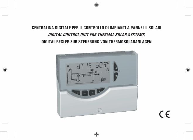
CENTRALINA DIGITALE PER IL CONTROLLO DI IMPIANTI A PANNELLI SOLARI
DIGITAL CONTROL UNIT FOR THERMAL SOLAR SYSTEMS
DIGITAL REGLER ZUR STEUERUNG VON THERMOSOLARANLAGEN

2
ACCESSORI E RICAMBI DISPONIBILI
AVAILABLE ACCESSORIES AND SPARES
VERFÜGBARE ZUBEHÖR- UND ERSATZTEILE
Accessorio per contatti puliti: 2 ingressi 230V~ e 2 uscite contatti puliti.Accessories for free contacts: 2 x 230V~ inputs and 2 free voltage outputs.Zubehör für pot. freie Kontakte: 2 Eingängen 230V~ und 2 ausgängen freie kontakte.
Sonda Pt1000 -50°C .. +200°C cavo grigio.Pt1000 probe -50°C .. +200°C grey cable.Fühler Pt1000 -50°C .. +200°C graues Kabel.
Sonda Pt1000 -50°C .. +110°C cavo blu.Pt1000 probe -50°C .. +110°C blue cable.Fühler Pt1000 -50°C .. +110°C blaues Kabel.
Pozzetto in ottone 1/2” 6x33mm.Brass pocket 1/2” 6x33mm.Schutzrohr aus Messing 1/2” 6x33mm.
Staffa in ferro zincato per fissaggio centralina su pannello.Zinc-plated iron fitting for fixing the control unit on a panel.Pratze aus verzinktem Eisen zur Befestigung des Gehäuses an der Platte.
•
•
•
•
•

3
INSTALLAZIONE / INSTALLATION / AUFSTELLUNG
FIG. 5 - ABB. 5FIG. 4 - ABB. 4
4 5
AUFS
TELL
UNG
INST
ALLA
TION
INST
ALLA
ZION
E
FIG. 1 - ABB. 11 FIG. 3 - ABB. 33
FIG. 2 - ABB. 22
4
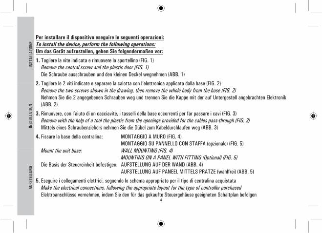
Per installare il dispositivo eseguire le seguenti operazioni:To install the device, perform the following operations:Um das Gerät aufzustellen, gehen Sie folgendermaßen vor:
1. Togliere la vite indicata e rimuovere lo sportellino (FIG. 1) Remove the central screw and the plastic door (FIG. 1) Die Schraube ausschrauben und den kleinen Deckel wegnehmen (ABB. 1)
2. Togliere le 2 viti indicate e separare la calotta con l’elettronica applicata dalla base (FIG. 2) Remove the two screws shown in the drawing, then remove the whole body from the base (FIG. 2) Nehmen Sie die 2 angegebenen Schrauben weg und trennen Sie die Kappe mit der auf Untergestell angebrachten Elektronik
(ABB. 2)
3. Rimuovere, con l’aiuto di un cacciavite, i tasselli della base occorrenti per far passare i cavi (FIG. 3) Remove with the help of a tool the plastic from the openings provided for the cables pass-through (FIG. 3) Mittels eines Schraubenziehers nehmen Sie die Dübel zum Kabeldurchlaufen weg (ABB. 3)
4. Fissare la base della centralina: MONTAGGIO A MURO (FIG. 4) MONTAGGIO SU PANNELLO CON STAFFA (opzionale) (FIG. 5) Mount the unit base: WALL MOUNTING (FIG. 4) MOUNTING ON A PANEL WITH FITTING (Optional) (FIG. 5) Die Basis der Steuereinheit befestigen: AUFSTELLUNG AUF DER WAND (ABB. 4) AUFSTELLUNG AUF PANEEL MITTELS PRATZE (wahlfrei) (ABB. 5)
5. Eseguire i collegamenti elettrici, seguendo lo schema appropriato per il tipo di centralina acquistata Make the electrical connections, following the appropriate layout for the type of controller purchased Elektroanschlüsse vornehmen, indem Sie den für das gekaufte Steuergehäuse geeigneten Schaltplan befolgen
AUFS
TELL
UNG
INST
ALLA
TION
INST
ALLA
ZION
E

5
AUFS
TELL
UNG
INST
ALLA
TION
INST
ALLA
ZION
E
9 8 7 6 345 2 1
CARICO4N L
CARICO3N L
CARICO2N L
CARICO1N L C
ALLARME 230V~
50Hz±10%
N L
1 71 61 51 41 31 21 11 01
S4 3S S12S NC AN
19 8
OUT 4 ALLARMEALARMALARM
OUT 2 OUT 1OUT 3
VERSIONE CON 4 USCITE A RELE’ ON-OFF SPST, CONTATTI SOTTO TENSIONEVERSION WITH 4 SPST ON-OFF RELAY OUTPUTS, CONTACTS POWEREDVERSION MIT 4 ON/OFF SPST RELAISAUSGÄNGEN, KONTAKTE UNTER SPANNUNG
ATTENZIONE! Prima di effettuare qualsiasi collegamento accertarsi che la rete elettrica sia scollegata.WARNING! Before wiring the appliance be sure to turn the mains power off.ACHTUNG! Vor jeglicher Ausführung von Verbindungen sicherstellen, dass die Stromversorgung abgeschaltet ist.?
6
AUFS
TELL
UNG
INST
ALLA
TION
INST
ALLA
ZION
E
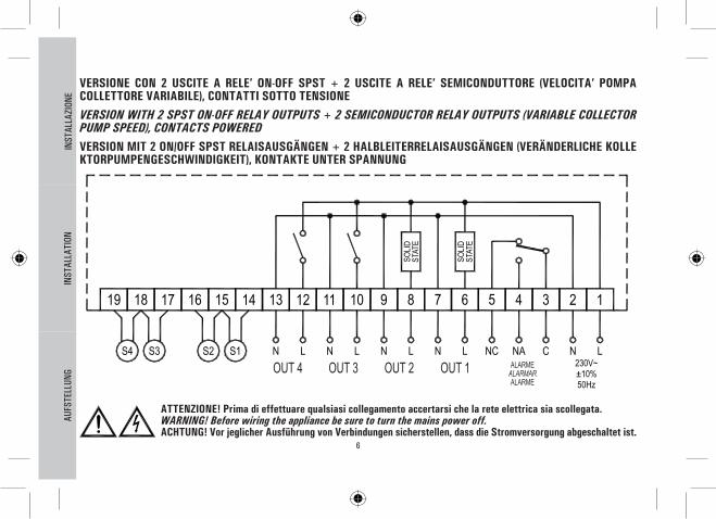
VERSIONE CON 2 USCITE A RELE’ ON-OFF SPST + 2 USCITE A RELE’ SEMICONDUTTORE (VELOCITA’ POMPA COLLETTORE VARIABILE), CONTATTI SOTTO TENSIONEVERSION WITH 2 SPST ON-OFF RELAY OUTPUTS + 2 SEMICONDUCTOR RELAY OUTPUTS (VARIABLE COLLECTOR PUMP SPEED), CONTACTS POWEREDVERSION MIT 2 ON/OFF SPST RELAISAUSGÄNGEN + 2 HALBLEITERRELAISAUSGÄNGEN (VERÄNDERLICHE KOLLEKTORPUMPENGESCHWINDIGKEIT), KONTAKTE UNTER SPANNUNG
ATTENZIONE! Prima di effettuare qualsiasi collegamento accertarsi che la rete elettrica sia scollegata.WARNING! Before wiring the appliance be sure to turn the mains power off.ACHTUNG! Vor jeglicher Ausführung von Verbindungen sicherstellen, dass die Stromversorgung abgeschaltet ist.?
ALARMEALARMARALARME
OUT 4 OUT 2 OUT 1OUT 3
7
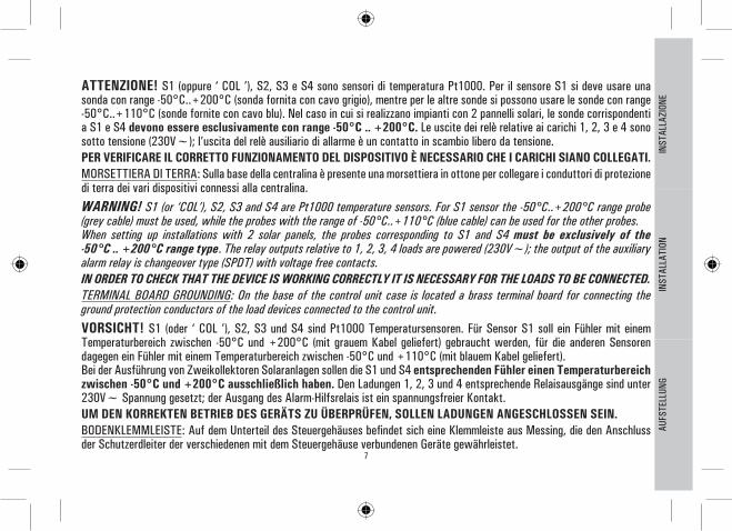
ATTENZIONE! S1 (oppure ‘ COL ’), S2, S3 e S4 sono sensori di temperatura Pt1000. Per il sensore S1 si deve usare una sonda con range -50°C..+200°C (sonda fornita con cavo grigio), mentre per le altre sonde si possono usare le sonde con range -50°C..+110°C (sonde fornite con cavo blu). Nel caso in cui si realizzano impianti con 2 pannelli solari, le sonde corrispondenti a S1 e S4 devono essere esclusivamente con range -50°C .. +200°C. Le uscite dei relè relative ai carichi 1, 2, 3 e 4 sono sotto tensione (230V~); l’uscita del relè ausiliario di allarme è un contatto in scambio libero da tensione.PER VERIFICARE IL CORRETTO FUNZIONAMENTO DEL DISPOSITIVO È NECESSARIO CHE I CARICHI SIANO COLLEGATI.MORSETTIERA DI TERRA: Sulla base della centralina è presente una morsettiera in ottone per collegare i conduttori di protezione di terra dei vari dispositivi connessi alla centralina.WARNING! S1 (or ‘COL’), S2, S3 and S4 are Pt1000 temperature sensors. For S1 sensor the -50°C..+200°C range probe (grey cable) must be used, while the probes with the range of -50°C..+110°C (blue cable) can be used for the other probes.When setting up installations with 2 solar panels, the probes corresponding to S1 and S4 must be exclusively of the -50°C .. +200°C range type. The relay outputs relative to 1, 2, 3, 4 loads are powered (230V~); the output of the auxiliary alarm relay is changeover type (SPDT) with voltage free contacts.IN ORDER TO CHECK THAT THE DEVICE IS WORKING CORRECTLY IT IS NECESSARY FOR THE LOADS TO BE CONNECTED.TERMINAL BOARD GROUNDING: On the base of the control unit case is located a brass terminal board for connecting the ground protection conductors of the load devices connected to the control unit.VORSICHT! S1 (oder ‘ COL ’), S2, S3 und S4 sind Pt1000 Temperatursensoren. Für Sensor S1 soll ein Fühler mit einem Temperaturbereich zwischen -50°C und +200°C (mit grauem Kabel geliefert) gebraucht werden, für die anderen Sensoren dagegen ein Fühler mit einem Temperaturbereich zwischen -50°C und +110°C (mit blauem Kabel geliefert).Bei der Ausführung von Zweikollektoren Solaranlagen sollen die S1 und S4 entsprechenden Fühler einen Temperaturbereich zwischen -50°C und +200°C ausschließlich haben. Den Ladungen 1, 2, 3 und 4 entsprechende Relaisausgänge sind unter 230V~ Spannung gesetzt; der Ausgang des Alarm-Hilfsrelais ist ein spannungsfreier Kontakt.UM DEN KORREKTEN BETRIEB DES GERÄTS ZU ÜBERPRÜFEN, SOLLEN LADUNGEN ANGESCHLOSSEN SEIN.BODENKLEMMLEISTE: Auf dem Unterteil des Steuergehäuses befindet sich eine Klemmleiste aus Messing, die den Anschluss der Schutzerdleiter der verschiedenen mit dem Steuergehäuse verbundenen Geräte gewährleistet.
AUFS
TELL
UNG
INST
ALLA
TION
INST
ALLA
ZION
E

8
6. Chiudere la centralina Close the control unit case Schließen Sie das Gehäuse
ATTENZIONE!Nel chiudere la centralina accertarsi che le morsettiere estraibili siano state inserite correttamente (le viti delle morsettiere devono essere rivolte verso l’alto).
ATTENTION!When closing the unit please ensure that the removable wiring terminals have been inserted with the correct orientation (the terminals screws must be facing upward).
ACHTUNG!Wenn Sie das Gehäuse schließen, vergewissern Sie sich, dass die Klemmleisten, die herausgezogen werden können, geeignet eingesetzt sind, bzw. die Schrauben der Klemmleisten müssen nach oben orientiert sein.AU
FSTE
LLUN
GIN
STAL
LATI
ONIN
STAL
LAZI
ONE
6

9
DESCRIZIONE DEI COMANDI / DESCRIPTION OF THE KEYS / BESCHREIBUNG DER BEFEHLE
TASTO MENUMENU KEYTASTE MENU
TASTO ANNULLACANCEL KEYTASTE LÖSCHEN
TASTO MANUALEMANUAL KEYTASTE MANUELL
TASTO CONFERMACONFIRMATION KEYTASTE BESTÄTIGUNG
TASTI DI SELEZIONESELECTION KEYSWAHLTASTE
TASTO RESETRESET KEYTASTE RESET

10
Le seguenti logiche di controllo vanno applicate a tutti gli schemi di seguito illustrati.The following control logics must be applied to all the diagram described hereinafterFolgende steuerlogiken sind auf alle hier unten dargestellten schaltpläne anzuwenden.
•
Logica di controllo dei termostati di sicurezza / Control logic of the safety thermostats / Steuerlogik der Sicherheitsthermostaten
Il controllo non è attivo con la centralina in stato di ‘ OFF ‘.
The control is not active when the unit is in ‘ OFF ‘ status.
Die Steuerung ist nicht aktiv, wenn das Gehäuse im ‘ OFF ‘ Zustand ist.
TS1 TS3TS2 TS4
RE
LE' A
LR
RELE’ ALR / ALR RELAY /RELAIS ALR
Logica di controllo in MANUALE o in ABC / Control logic in MANUAL mode or in ABC / Steuerlogik in MANUELL oder ABC
La logica di controllo relativa ai comandi della funzione ‘ABC’ o del funzionamento ‘ MANUALE ‘, si sostituisce al controllo del differenziale. Rimangono sempre attivi i controlli relativi alle temperature Massime e di Sicurezza. La fonte integrativa in modalità Manuale o ABC viene disinserita.Si reinserirà automaticamente alla disattivazione delle suddette modalità.
The control logic concerning the commands of the ‘ABC’ function or the ‘ MANUAL ‘ operation mode takes the place of the differential gear control. The controls concerning the Safety and Maximum temperatures are always active. The integrative source in Manual mode or in ABC is deactivated. It will be automatically reactivated when the above modes are deactivated.
Die Steuerlogik, die den Steuerungen der ‘ABC’ Funktion oder der ‘ MANUELLEN ‘ Betriebsart entspricht, ersetzt die Steuerung des Differentials. Die Steuerung der Höchst- bzw. Sicherheitstemperaturen bleibt immer aktiv. Die Integrierquelle in der manuellen bzw. ABC Betriebsart wird ausgeschaltet. Die wird bei der Ausschaltung dieser Betriebsarten automatisch wieder eingeschaltet.
ABC
MANUALE
T/ABC
IN PARALLELO AL CONTROLLO DEL T
/1 0 MANUALE IN PARALLELO AL CONTROLLO DEL ∆TMANUAL IN PARALLEL TO THE ∆T CONTROLMANUELL PARALLEL ZUR ∆T STEUERUNG
SCHE
MA
DIAG
RAM
SCHE
MA
P1: SELEZIONE TIPO IMPIANTO / SELECTION INSTALLATION TYPE / WAHL DES ANLAGENTYPS

11
SCH 01Sistema di riscaldamento solare con 1 serbatoio, e riscaldamento integrativo escluso.
Solar heating installation with 1 tank and no integrative heat source.
Solarheizanlage mit 1 Behälter, Integrierheizung ausgeschlossen.
ATTENZIONE! Tutte le uscite forniscono tensione a 230V~.WARNING! All outputs are 230V~ powered and are NOT potential free.ACHTUNG! Alle Ausgänge liefern 230V~ Spannung.?
1/ 0AFR
TAF
T1-2
TM3
TS1
TS3
TS2
OU
T 1
Logica di controllo / Control logic / Steuerlogik
TS1-TS2-TS3: Temperatura di sicurezza sulle sonde / Probe safety temperature / Sicherheitstemperatur auf Fühlern∆T 12: Differenziale tra le sonde S1-S2 / Differential between the probes S1-S2 / Differenzierung Fühlern S1 und S2TM3: Temperatura massima sulla sonda S3 / Maximum temperature of probe S3 / Höchsttemperatur auf Fühler S3HY12: Isteresi del ∆T 12 / Hysteresis of ∆T 12 / ∆T 12 HystereseHYT: Isteresi termostati / Thermostatic hysteresis / Hysterese Thermostaten HYTS: Isteresi termostati di sicurezza / Safety thermostatic hysteresis / Hysterese Sicherheitsthermostaten
Eventuali dati termici da impostare.Eventual thermal data to be programmed.Eventuell einzustellende Wärmewerte.
SCHE
MA
DIAG
RAM
SCHE
MA

12
SCH 02Sistema di riscaldamento solare con 1 serbatoio e riscaldamento integrativo incluso.
Solar heating installation with 1 tank and additional thermostatic heating.
Solarheizanlage mit 1 Behälter und thermostatischer Integrierheizung.
TS1-TS2-TS3: Temperatura di sicurezza sulle sonde / Probe safety temperature / Sicherheitstemperatur auf Fühlern∆T 12: Differenziale tra le sonde S1-S2 / Differential between the probes S1-S2 / Differenzierung Fühlern S1 und S2TM3: Temperatura massima sulla sonda S3 / Maximum temperature of the probe S3 / Höchsttemperatur auf Fühler S3TAH: Temperatura di integrazione sulla sonda S3 / Integration temperature on the probe S3 / Integriertemperatur auf Fühler S3HY12: Isteresi del ∆T 12 / Hysteresis of ∆T 12 / ∆T 12 HystereseHYT: Isteresi termostati / Thermostatic hysteresis / Hysterese Thermostaten HYTS: Isteresi termostati di sicurezza / Safety thermostatic hysteresis / Hysterese Sicherheitsthermostaten
ATTENZIONE! Tutte le uscite forniscono tensione a 230V~.WARNING! All outputs are 230V~ powered and are NOT potential free.ACHTUNG! Alle Ausgänge liefern 230V~ Spannung.?
Eventuali dati termici da impostare.Eventual thermal data to be programmed.Eventuell einzustellende Wärmewerte.
OU
T 1
TS2
TS3
TS1T1-2
TM3
TAF
AFR/1 0
OU
T 2
TAH TAH
OU
T 3
Logica di controllo / Control logic / Steuerlogik
SCHE
MA
DIAG
RAM
SCHE
MA

13
SCH 03Sistema di riscaldamento solare per piscina.Pool solar heating installation.Solarheizanlage für Schwimmbad.
TS1-TS2-TS3: Temperatura di sicurezza sulle sonde / Probe safety temperature / Sicherheitstemperatur auf Fühlern∆T 12: Differenziale tra le sonde S1-S2 / Differential between the probes S1-S2 / Differenzierung Fühlern S1 und S2TM3: Temperatura massima sulla sonda S3 / Maximum temperature of the probe S3 / Höchsttemperatur auf Fühler S3HY12: Isteresi del ∆T 12 / Hysteresis of ∆T 12 / ∆T 12 HystereseHYT: Isteresi termostati / Thermostatic hysteresis / Hysterese ThermostatenHYTS: Isteresi termostati di sicurezza / Safety thermostatic hysteresis / Hysterese Sicherheitsthermostaten
ATTENZIONE! Tutte le uscite forniscono tensione a 230V~.WARNING! All outputs are 230V~ powered and are NOT potential free.ACHTUNG! Alle Ausgänge liefern 230V~ Spannung.?
Eventuali dati termici da impostare.Eventual thermal data to be programmed.Eventuell einzustellende Wärmewerte.
1/ 0AFR
TAF
T1-2
TM3
TS1
TS3
TS2
OU
T 1
Logica di controllo / Control logic / Steuerlogik
SCHE
MA
DIAG
RAM
SCHE
MA

14
SCH 04Sistema di riscaldamento solare con 1 serbatoio, integrazione diretta mediante logica di valvola.
Solar heating installation with 1 tank, direct integration by means of valve logic.
Solarheizanlage mit 1 Behälter, direkte Integrierung durch Ventillogik.
TS1-TS2-TS3: Temperatura di sicurezza sulle sonde / Probe safety temperature / Sicherheitstemperatur auf Fühlern∆T 12: Differenziale tra le sonde S1-S2 / Differential between the probes S1-S2 / Differenzierung Fühlern S1 und S2TM3: Temperatura massima sulla sonda S3 / Maximum temperature of the probe S3 / Höchsttemperatur auf Fühler S3TAH: Temperatura di integrazione sulla sonda S3 / Integration temperature on the probe S3 / Integriertemperatur auf Fühler S3HY12: Isteresi del ∆T 12 / Hysteresis of ∆T 12 / ∆T 12 HystereseHYT: Isteresi termostati / Thermostatic hysteresis / Hysterese Thermostaten HYTS: Isteresi termostati di sicurezza / Safety thermostatic hysteresis / Hysterese Sicherheitsthermostaten
ATTENZIONE! Tutte le uscite forniscono tensione a 230V~.WARNING! All outputs are 230V~ powered and are NOT potential free.ACHTUNG! Alle Ausgänge liefern 230V~ Spannung.?
Eventuali dati termici da impostare.Eventual thermal data to be programmed.Eventuell einzustellende Wärmewerte.
OU
T 1
TS2
TS3
TS1T1-2
TM3
TAF
AFR/1 0
OU
T 2
TAH TAH
OU
T 3
Logica di controllo / Control logic / Steuerlogik
SCHE
MA
DIAG
RAM
SCHE
MA

15
SCH 05Sistema di riscaldamento solare a circolazione naturale con 1 serbatoio e integrazione diretta mediante logica di valvola.Natural circulation solar heating installation with 1 tank and direct integration by means of valve logic.Solarheizanlage durch natürliche Zirkulation, mit 1 Behälter. Direkte Integrierung durch Ventillogik.
TS1-TS2-TS3: Temperatura di sicurezza sulle sonde / Probe safety temperature / Sicherheitstemperatur auf FühlernTAH: Temperatura di integrazione sulla sonda S3 / Integration temperature on the probe S3 / Integriertemperatur auf Fühler S3HYT: Isteresi termostati / Thermostatic hysteresis / Hysterese Thermostaten HYTS: Isteresi termostati di sicurezza / Safety thermostatic hysteresis / Hysterese Sicherheitsthermostaten
ATTENZIONE! Tutte le uscite forniscono tensione a 230V~.WARNING! All outputs are 230V~ powered and are NOT potential free.ACHTUNG! Alle Ausgänge liefern 230V~ Spannung.?
Eventuali dati termici da impostare.Eventual thermal data to be programmed.Eventuell einzustellende Wärmewerte.
TAH
OU
T 1
TAH
OU
T 2
Logica di controllo / Control logic / Steuerlogik
SCHE
MA
DIAG
RAM
SCHE
MA

16
SCH 06Sistema di riscaldamento solare con 2 serbatoi, controllo con logica di valvola, integrazione esclusa.
Solar heating installation with 2 tanks, valve logic control and no integrative heat source.
Solarheizanlage mit 2 Behältern, Kontrolle mit Ventillogik, Integrierung ausgeschlossen.
TS1-TS2-TS3-TS4: Temperatura di sicurezza sulle sonde / Probe safety temperature / Sicherheitstemperatur auf Fühlern∆T 12: Differenziale tra le sonde S1-S2 / Differential between the probes S1-S2 / Differenzierung Fühlern S1 und S2∆T 14: Differenziale tra le sonde S1-S4 / Differential between the probes S1-S4 / Differenzierung Fühlern S1 und S4TM3: Temperatura massima sulla sonda S3 / Maximum temperature of the probe S3 / Höchsttemperatur auf Fühler S3TM4: Temperatura massima sulla sonda S4 / Maximum temperature of the probe S4 / Höchsttemperatur auf Fühler S4HY12: Isteresi del ∆T 12 / Hysteresis of ∆T 12 / ∆T 12 HystereseHY14: Isteresi del ∆T 14 / Hysteresis of ∆T 14 / ∆T 14 HystereseHYT: Isteresi termostati / Thermostatic hysteresis / Hysterese Thermostaten HYTS: Isteresi termostati di sicurezza / Safety thermostatic hysteresis / Hysterese Sicherheitsthermostaten
ATTENZIONE! Tutte le uscite forniscono tensione a 230V~.WARNING! All outputs are 230V~ powered and are NOT potential free.ACHTUNG! Alle Ausgänge liefern 230V~ Spannung.?
Eventuali dati termici da impostare.Eventual thermal data to be programmed.Eventuell einzustellende Wärmewerte.
AFR
TAF
T1-2 T1-4
01/ OU
T 1
TM3
OU
T 2
TS1
TM3
TS2
TM3
TM4
TS1
Logica di controllo / Control logic / Steuerlogik
SCHE
MA
DIAG
RAM
SCHE
MA

17
SCH 07Sistema di riscaldamento solare con 2 serbatoi, controllo con logica di valvola e riscaldamento integrativo.
Solar heating installation with 2 tanks, logic valve control, and integrative heat source.
Solarheizanlage mit 2 Behältern, Kontrolle mit Ventillogik und Integrierheizung.
TS1-TS2-TS3-TS4: Temperatura di sicurezza sulle sonde / Probe safety temperature / Sicherheitstemperatur auf Fühlern∆T 12: Differenziale tra le sonde S1-S2 / Differential between the probes S1-S2 / Differenzierung Fühlern S1 und S2∆T 14: Differenziale tra le sonde S1-S4 / Differential between the probes S1-S4 / Differenzierung Fühlern S1 und S4TM3: Temperatura massima sulla sonda S3 / Maximum temperature of the probe S3 / Höchsttemperatur auf Fühler S3TM4: Temperatura massima sulla sonda S4 / Maximum temperature of the probe S4 / Höchsttemperatur auf Fühler S3TAH: Temperatura di integrazione sulla sonda S3 / Integration temperature on the probe S3 / Integriertemperatur auf Fühler S3HY12: Isteresi del ∆T 12 / Hysteresis of ∆T 12 / ∆T 12 HystereseHY14: Isteresi del ∆T 14 / Hysteresis of ∆T 14 / ∆T 14 HystereseHYT: Isteresi termostati / Thermostatic hysteresis / Hysterese Thermostaten HYTS: Isteresi termostati di sicurezza / Safety thermostatic hysteresis / Hysterese Sicherheitsthermostaten
ATTENZIONE! Tutte le uscite forniscono tensione a 230V~.WARNING! All outputs are 230V~ powered and are NOT potential free.ACHTUNG! Alle Ausgänge liefern 230V~ Spannung.?
Eventuali dati termici da impostare.Eventual thermal data to be programmed.Eventuell einzustellende Wärmewerte.
TS1
OU
T 1
TM4TS2
TM3TM3
TS1
AFR
TAF
T1-2 T1-4
/1 0 OU
T 2
TAH TM3
OU
T 3
OU
T 4
TAH
Logica di controllo / Control logic / Steuerlogik
SCHE
MA
DIAG
RAM
SCHE
MA

18
SCH 08Sistema di riscaldamento solare con 2 serbatoi, controllo con logica di valvola, integrazione esclusa.
Solar heating installation with 2 tanks, valve logic control, no integrative heat source.
Solarheizanlage mit 2 Behältern, Kontrolle mit Ventillogik, Integrierung ausgeschlossen.
TS1-TS2-TS3-TS4: Temperatura di sicurezza sulle sonde / Probe safety temperature / Sicherheitstemperatur auf Fühlern∆T 12: Differenziale tra le sonde S1-S2 / Differential between the probes S1-S2 / Differenzierung Fühlern S1 und S2∆T 14: Differenziale tra le sonde S1-S4 / Differential between the probes S1-S4 / Differenzierung Fühlern S1 und S4TM3: Temperatura massima sulla sonda S3 / Maximum temperature of the probe S3 / Höchsttemperatur auf Fühler S3TM4: Temperatura massima sulla sonda S4 / Maximum temperature of the probe S4 / Höchsttemperatur auf Fühler S4HY12: Isteresi del ∆T 12 / Hysteresis of ∆T 12 / ∆T 12 HystereseHY14: Isteresi del ∆T 14 / Hysteresis of ∆T 14 / ∆T 14 HystereseHYT: Isteresi termostati / Thermostatic hysteresis / Hysterese Thermostaten HYTS: Isteresi termostati di sicurezza / Safety thermostatic hysteresis / Hysterese Sicherheitsthermostaten
ATTENZIONE! Tutte le uscite forniscono tensione a 230V~.WARNING! All outputs are 230V~ powered and are NOT potential free.ACHTUNG! Alle Ausgänge liefern 230V~ Spannung.?
Eventuali dati termici da impostare.Eventual thermal data to be programmed.Eventuell einzustellende Wärmewerte.
TM3TS2
TM3
TS1
TM3
TM4
TS1
OU
T 1
OU
T 3
AFR
TAF
T1-2 T1-4 T1-4
01/ OU
T 2
TM4
TM3
Logica di controllo / Control logic / Steuerlogik
SCHE
MA
DIAG
RAM
SCHE
MA

19
SCH 09Sistema di riscaldamento solare con 1 serbatoio, controllo con logica di valvola, scambiatore per utenza aggiuntiva “Bacino Piscina”.Solar heating installation with 1 tank, valve logic control and heat exchanger for pool heating.Solarheizanlage mit 1 Behälter, Kontrolle mit Ventillogik, Austauscher für zusätzlichen Verbraucher “Schwimmbad Becken”.
TS1-TS2-TS3-TS4: Temperatura di sicurezza sulle sonde / Probe safety temperature / Sicherheitstemperatur auf Fühlern∆T 12: Differenziale tra le sonde S1-S2 / Differential between the probes S1-S2 / Differenzierung Fühlern S1 und S2∆T 14: Differenziale tra le sonde S1-S4 / Differential between the probes S1-S4 / Differenzierung Fühlern S1 und S4TM3: Temperatura massima sulla sonda S3 / Maximum temperature of the probe S3 / Höchsttemperatur auf Fühler S3TM4: Temperatura massima sulla sonda S4 / Maximum temperature of the probe S4 / Höchsttemperatur auf Fühler S4HY12: Isteresi del ∆T 12 / Hysteresis of ∆T 12 / ∆T 12 HystereseHY14: Isteresi del ∆T 14 / Hysteresis of ∆T 14 / ∆T 14 HystereseHYT: Isteresi termostati / Thermostatic hysteresis / Hysterese ThermostatenHYTS: Isteresi termostati di sicurezza / Safety thermostatic hysteresis / Hysterese Sicherheitsthermostaten
ATTENZIONE! Tutte le uscite forniscono tensione a 230V~.WARNING! All outputs are 230V~ powered and are NOT potential free.ACHTUNG! Alle Ausgänge liefern 230V~ Spannung.?
Eventuali dati termici da impostare.Eventual thermal data to be programmed.Eventuell einzustellende Wärmewerte.
TM3TS2
TM3
TS1
TM3
TM4
TS1
OU
T 1
OU
T 3
AFR
TAF
T1-2 T1-4 T1-4
01/ OU
T 2
TM4
TM3
Logica di controllo / Control logic / Steuerlogik
SCHE
MA
DIAG
RAM
SCHE
MA

20
SCH 10Sistema di riscaldamento solare con 2 serbatoi, regolazione sanitari con scambio termico e riscaldamento integrativo.Solar heating installation with 2 tanks, sanitary regulation with thermal exchange and integrative heat source.Solarheizanlage mit 2 Behältern, Einstellung dersanitären Anlagen mit Wärmeaustausch und Integrierheizung.
TS1-TS2-TS3-TS4: Temperatura di sicurezza sulle sonde / Probe safety temperature / Sicherheitstemperatur auf Fühlern∆T 12: Differenziale tra le sonde S1-S2 / Differential between the probes S1-S2 / Differenzierung Fühlern S1 und S2∆T 34: Differenziale tra le sonde S3-S4 / Differential between the probes S3-S4 / Differenzierung Fühlern S3 und S4TM3: Temperatura massima sulla sonda S3 / Maximum temperature of the probe S3 / Höchsttemperatur auf Fühler S3TM4: Temperatura massima sulla sonda S4 / Maximum temperature of the probe S4 / Höchsttemperatur auf Fühler S4TAH: Temperatura di integrazione sulla sonda S3 / Integration temperature on the probe S3 / Integriertemperatur auf Fühler S3HY12: Isteresi del ∆T 12 / Hysteresis of ∆T 12 / ∆T 12 HystereseHY34: Isteresi del ∆T 34 / Hysteresis of ∆T 34 / ∆T 34 HystereseHYT: Isteresi termostati / Thermostatic hysteresis / Hysterese Thermostaten HYTS: Isteresi termostati di sicurezza / Safety thermostatic hysteresis / Hysterese Sicherheitsthermostaten
ATTENZIONE! Tutte le uscite forniscono tensione a 230V~.WARNING! All outputs are 230V~ powered and are NOT potential free.ACHTUNG! Alle Ausgänge liefern 230V~ Spannung.?
Eventuali dati termici da impostare.Eventual thermal data to be programmed.Eventuell einzustellende Wärmewerte.
AFRT1-2
T3-4
OU
T 3
TAH TAH
OU
T 4/1 0 TM3
TAF
TS1
OU
T 1
TS2
TS3 OU
T 2
TM4
Logica di controllo / Control logic / Steuerlogik
SCHE
MA
DIAG
RAM
SCHE
MA

21
SCH 11Sistema di riscaldamento solare con 1 serbatoio e sistema integrativo a combustibile solido.
Solar heating installation with 1 tank and additional heat source with solid fuel.
Solarheizanlage mit 1 Behälter und Integrieranlage mit festem Brennstoff laufend.
TS1-TS2-TS3-TS4: Temperatura di sicurezza sulle sonde / Probe safety temperature / Sicherheitstemperatur auf Fühlern∆T 12: Differenziale tra le sonde S1-S2 / Differential between the probes S1-S2 / Differenzierung Fühlern S1 und S2∆T 43: Differenziale tra le sonde S4-S3 / Differential between the probes S4-S3 / Differenzierung Fühlern S4 und S3TM3: Temperatura massima sulla sonda S3 / Maximum temperature of the probe S3 / Höchsttemperatur auf Fühler S3TM4: Temperatura massima sulla sonda S4 / Maximum temperature of the probe S4 / Höchsttemperatur auf Fühler S4HY12: Isteresi del ∆T 12 / Hysteresis of ∆T 12 / ∆T 12 HystereseHY43: Isteresi del ∆T 43 / Hysteresis of ∆T 43 / ∆T 43 HystereseHYT: Isteresi termostati / Thermostatic hysteresis / Hysterese ThermostatenHYTS: Isteresi termostati di sicurezza / Safety thermostatic hysteresis / Hysterese Sicherheitsthermostaten
ATTENZIONE! Tutte le uscite forniscono tensione a 230V~.WARNING! All outputs are 230V~ powered and are NOT potential free.ACHTUNG! Alle Ausgänge liefern 230V~ Spannung.?
Eventuali dati termici da impostare.Eventual thermal data to be programmed.Eventuell einzustellende Wärmewerte.
TAF
TS1
TS3
TS2
TM3
OU
T 1
AFRT1-2
T4-3/1 0
TM4
OU
T 2
Logica di controllo / Control logic / Steuerlogik
SCHE
MA
DIAG
RAM
SCHE
MA

22
SCH 12Sistema di riscaldamento solare con 1 serbatoio, riscaldamento integrativo e a combustibile solido.
Solar heating installation with 1 tank plus one integrative and one solid fuel heat sources.
Solarheizanlage mit 1 Behälter und Integrierheizung. Mit festem Brennstoff laufend.
TS1-TS2-TS3-TS4: Temperatura di sicurezza sulle sonde / Probe safety temperature / Sicherheitstemperatur auf Fühlern∆T 12: Differenziale tra le sonde S1-S2 / Differential between the probes S1-S2 / Differenzierung Fühlern S1 und S2∆T 43: Differenziale tra le sonde S4-S3 / Differential between the probes S4-S3 / Differenzierung Fühlern S4 und S3TM3: Temperatura massima sulla sonda S3 / Maximum temperature of the probe S3 / Höchsttemperatur auf Fühler S3TM4: Temperatura massima sulla sonda S4 / Maximum temperature of the probe S4 / Höchsttemperatur auf Fühler S4TAH: Temperatura di integrazione sulla sonda S3 / Integration temperature on the probe S3 / Integriertemperatur auf Fühler S3HY12: Isteresi del ∆T 12 / Hysteresis of ∆T 12 / ∆T 12 HystereseHY43: Isteresi del ∆T 43 / Hysteresis of ∆T 43 / ∆T 43 HystereseHYT: Isteresi termostati / Thermostatic hysteresis / Hysterese Thermostaten HYTS: Isteresi termostati di sicurezza / Safety thermostatic hysteresis / Hysterese Sicherheitsthermostaten
ATTENZIONE! Tutte le uscite forniscono tensione a 230V~.WARNING! All outputs are 230V~ powered and are NOT potential free.ACHTUNG! Alle Ausgänge liefern 230V~ Spannung.?
Eventuali dati termici da impostare.Eventual thermal data to be programmed.Eventuell einzustellende Wärmewerte.
TAF
TS1
TS3
TS2
TM3
OU
T 1
AFRT1-2
T4-3
TAH TAH
1/ 0
TM4
OU
T 2
OU
T 4
OU
T 3
Logica di controllo / Control logic / Steuerlogik
SCHE
MA
DIAG
RAM
SCHE
MA

23
SCH 13Sistema di riscaldamento solare con 2 serbatoi, logica di pompa.
Solar heating installation with 2 tanks, pump logic.
Solarheizanlage mit 2 Behältern und Pumpenlogik.
TS1-TS2-TS3-TS4: Temperatura di sicurezza sulle sonde / Probe safety temperature / Sicherheitstemperatur auf Fühlern∆T 12: Differenziale tra le sonde S1-S2 / Differential between the probes S1-S2 / Differenzierung Fühlern S1 und S2∆T 14: Differenziale tra le sonde S1-S4 / Differential between the probes S1-S4 / Differenzierung Fühlern S1 und S4TM3: Temperatura massima sulla sonda S3 / Maximum temperature of the probe S3 / Höchsttemperatur auf Fühler S3TM4: Temperatura massima sulla sonda S4 / Maximum temperature of the probe S4 / Höchsttemperatur auf Fühler S4HY12: Isteresi del ∆T 12 / Hysteresis of ∆T 12 / ∆T 12 HystereseHY14: Isteresi del ∆T 14 / Hysteresis of ∆T 14 / ∆T 14 HystereseHYT: Isteresi termostati / Thermostatic hysteresis / Hysterese Thermostaten HYTS: Isteresi termostati di sicurezza / Safety thermostatic hysteresis / Hysterese Sicherheitsthermostaten
ATTENZIONE! Tutte le uscite forniscono tensione a 230V~.WARNING! All outputs are 230V~ powered and are NOT potential free.ACHTUNG! Alle Ausgänge liefern 230V~ Spannung.?
Eventuali dati termici da impostare.Eventual thermal data to be programmed.Eventuell einzustellende Wärmewerte.
AFR
T1-2 T1-4
/1 0 TS2
TM3TAF
TS1
OU
T 1
OU
T 2
TM3
TM4
Logica di controllo / Control logic / Steuerlogik
SCHE
MA
DIAG
RAM
SCHE
MA

24
SCH 14Sistema di riscaldamento solare con 3 serbatoi, logica di pompa.Solar heating installation with 3 tanks, pump logic.Solarheizanlage mit 3 Behältern und Pumpenlogik.
TS1-TS2-TS3-TS4: Temperatura di sicurezza sulle sonde / Probe safety temperature / Sicherheitstemperatur auf Fühlern∆T 12: Differenziale tra le sonde S1-S2 / Differential between the probes S1-S2 / Differenzierung Fühler S1 und S2∆T 13: Differenziale tra le sonde S1-S3 / Differential between the probes S1-S3 / Differenzierung Fühler S1 und S3∆T 14: Differenziale tra le sonde S1-S4 / Differential between the probes S1-S4 / Differenzierung Fühler S1 und S4TM2: Temperatura massima sulla sonda S2 / Maximum temperature of the probe S2 / Höchsttemperatur auf Fühler S2TM3: Temperatura massima sulla sonda S3 / Maximum temperature of the probe S3 / Höchsttemperatur auf Fühler S3TM4: Temperatura massima sulla sonda S4 / Maximum temperature of the probe S4 / Höchsttemperatur auf Fühler S4HY12: Isteresi del ∆T 12 / Hysteresis of ∆T 12 / ∆T 12 HystereseHY13: Isteresi del ∆T 13 / Hysteresis of ∆T 13 / ∆T 13 HystereseHY14: Isteresi del ∆T 14 / Hysteresis of ∆T 14 / ∆T 14 HystereseHYT: Isteresi termostati / Thermostatic hysteresis / Hysterese Thermostaten HYTS: Isteresi termostati di sicurezza / Safety thermostatic hysteresis / Hysterese Sicherheitsthermostaten
ATTENZIONE! Tutte le uscite forniscono tensione a 230V~.WARNING! All outputs are 230V~ powered and are NOT potential free.ACHTUNG! Alle Ausgänge liefern 230V~ Spannung.?
Eventuali dati termici da impostare.Eventual thermal data to be programmed.Eventuell einzustellende Wärmewerte.
T1-2 T1-3 T1-4
TAF
AFR01/
OU
T 1
TM2
TS1 TS1
OU
T 2
TM2
TM3
TM2
TM3
TS1
OU
T 3
TM4
Logica di controllo / Control logic / Steuerlogik
SCHE
MA
DIAG
RAM
SCHE
MA

25
SCH 15Sistema di riscaldamento solare con 2 bancate di pannelli, 1 serbatoio e riscaldamento integrativo escluso.Solar heating installation with 2 banks of panels, 1 tank and no integrative heat source.Solarheizanlage mit 2 Reihen von Paneelen und 1 Behälter. Integrierheizung ausgeschlossen.
TS1-TS2-TS3-TS4: Temperatura di sicurezza sulle sonde / Probe safety temperature / Sicherheitstemperatur auf Fühlern∆T 12: Differenziale tra le sonde S1-S2 /Differential between the probes S1-S2 / Differenzierung Fühlern S1 und S2∆T 42: Differenziale tra le sonde S4-S2 / Differential between the probes S4-S2 / Differenzierung Fühlern S4 und S2TM3: Temperatura massima sulla sonda S3 / Maximum temperature of the probe S3 / Höchsttemperatur auf Fühler S3HY12: Isteresi del ∆T 12 / Hysteresis of ∆T 12 / ∆T 12 HystereseHY42: Isteresi del ∆T 42 / Hysteresis of ∆T 42 / ∆T 42 HystereseHYT: Isteresi termostati / Thermostatic hysteresis / Hysterese Thermostaten
ATTENZIONE! Tutte le uscite forniscono tensione a 230V~.WARNING! All outputs are 230V~ powered and are NOT potential free.ACHTUNG! Alle Ausgänge liefern 230V~ Spannung.?
Eventuali dati termici da impostare.Eventual thermal data to be programmed.Eventuell einzustellende Wärmewerte.
OU
T 1
TAF
TS2
TS3
TM3
TS1AFR
T1-2AFR
T4-2
TS2
TM3
TAF TS3
TS4
OU
T 201/01/
Logica di controllo / Control logic / Steuerlogik
SCHE
MA
DIAG
RAM
SCHE
MA

26
SCH 16Sistema di riscaldamento solare con 2 bancate di pannelli, 1 serbatoio e riscaldamento integrativo.
Solar heating installation with 2 banks of panels, 1 tank and integrative heat source.
Solarheizanlage mit 2 Reihen von Paneelen, 1 Behälter und Integrierheizung.
TS1-TS2-TS3-TS4: Temperatura di sicurezza sulle sonde / Probe safety temperature / Sicherheitstemperatur auf Fühlern∆T 12: Differenziale tra le sonde S1-S2 / Differential between the probes S1-S2 / Differenzierung Fühlern S1 und S2∆T 42: Differenziale tra le sonde S4-S2 / Differential between the probes S4-S2 / Differenzierung Fühlern S4 und S2TM3: Temperatura massima sulla sonda S3 / Maximum temperature of the probe S3 / Höchsttemperatur auf Fühler S3TAH: Temperatura di integrazione sulla sonda S3 / Integration temperature on the probe S3 / Integriertemperatur auf Fühler S3HY12: Isteresi del ∆T 12 / Hysteresis of ∆T 12 / ∆T 12 HystereseHY42: Isteresi del ∆T 42 / Hysteresis of ∆T 42 / ∆T 42 HystereseHYT: Isteresi termostati / Thermostatic hysteresis / Hysterese Thermostaten HYTS: Isteresi termostati di sicurezza / Safety thermostatic hysteresis / Hysterese Sicherheitsthermostaten
ATTENZIONE! Tutte le uscite forniscono tensione a 230V~.WARNING! All outputs are 230V~ powered and are NOT potential free.ACHTUNG! Alle Ausgänge liefern 230V~ Spannung.?
Eventuali dati termici da impostare.Eventual thermal data to be programmed.Eventuell einzustellende Wärmewerte.
TS1
TS2
TS3TAF
TM3
OU
T 1
TS4
TAF
TM3
TS2
OU
T 2
TS3
AFRT1-2
AFRT4-2
OU
T 4
TAH
OU
T 3
TAH
/1 0 01/
Logica di controllo / Control logic / Steuerlogik
SCHE
MA
DIAG
RAM
SCHE
MA

27
SCH 17Sistema di riscaldamento solare con 2 bancate di pannelli, 1 serbatoio, integrazione diretta mediante logica di valvola.
Solar heating installation with 2 banks of panels, 1 tank, integrative heat source by means of valve logic.
Solarheizanlage mit 2 Reihen von Paneelen, 1 Behälter, direkte Integrierung durch Ventillogik.
TS1-TS2-TS3-TS4: Temperatura di sicurezza sulle sonde / Probe safety temperature / Sicherheitstemperatur auf Fühlern∆T 12: Differenziale tra le sonde S1-S2 / Differential between the probes S1-S2 / Differenzierung Fühlern S1 und S2∆T 42: Differenziale tra le sonde S4-S2 / Differential between the probes S4-S2 / Differenzierung Fühlern S4 und S2TM3: Temperatura massima sulla sonda S3 / Maximum temperature of the probe S3 / Höchsttemperatur auf Fühler S3TAH: Temperatura di integrazione sulla sonda S3 / Integration temperature on the probe S3 / Integriertemperatur auf Fühler S3HY12: Isteresi del ∆T 12 / Hysteresis of ∆T 12 / ∆T 12 HystereseHY42: Isteresi del ∆T 42 / Hysteresis of ∆T 42 / ∆T 42 HystereseHYT: Isteresi termostati / Thermostatic hysteresis / Hysterese Thermostaten HYTS: Isteresi termostati di sicurezza / Safety thermostatic hysteresis / Hysterese Sicherheitsthermostaten
ATTENZIONE! Tutte le uscite forniscono tensione a 230V~.WARNING! All outputs are 230V~ powered and are NOT potential free.ACHTUNG! Alle Ausgänge liefern 230V~ Spannung.?
Eventuali dati termici da impostare.Eventual thermal data to be programmed.Eventuell einzustellende Wärmewerte.
TS1
TS2
TS3TAF
TM3
OU
T 1
TS4
TAF
TM3
TS2
OU
T 2
TS3
AFRT1-2
AFRT4-2
OU
T 4
TAH
OU
T 3
TAH
/1 0 01/
Logica di controllo / Control logic / Steuerlogik
SCHE
MA
DIAG
RAM
SCHE
MA

28
SCH 18Sistema di riscaldamento solare con 2 serbatoi, logica di valvola, riscaldamento integrativo, pompa aggiuntiva sul 2°boiler.Solar heating installation with 2 tanks, logic valve, integrative heat source, extra pump on the second boiler.Solarheizanlage mit 2 Behältern, Ventillogik, Integrierheizung, zusätzliche Pumpe auf 2. Kessel.
TS1-TS2-TS3-TS4: Temperatura di sicurezza sulle sonde / Probe safety temperature / Sicherheitstemperatur auf Fühlern∆T 12: Differenziale tra le sonde S1-S2 / Differential between the probes S1-S2 / Differenzierung Fühlern S1 und S2∆T 14: Differenziale tra le sonde S1-S4 / Differential between the probes S1-S4 / Differenzierung Fühlern S1 und S4TM3: Temperatura massima sulla sonda S3 / Maximum temperature of the probe S3 / Höchsttemperatur auf Fühler S3TM4: Temperatura massima sulla sonda S4 / Maximum temperature of the probe S4 / Höchsttemperatur auf Fühler S4TAH: Temperatura di integrazione sulla sonda S3 / Integration temperature on the probe S3 / Integriertemperatur auf Fühler S3HY12: Isteresi del ∆T 12 / Hysteresis of ∆T 12 / ∆T 12 HystereseHY14: Isteresi del ∆T 14 / Hysteresis of ∆T 14 / ∆T 14 HystereseHYT: Isteresi termostati / Thermostatic hysteresis / Hysterese Thermostaten HYTS: Isteresi termostati di sicurezza / Safety thermostatic hysteresis / Hysterese Sicherheitsthermostaten
ATTENZIONE! Tutte le uscite forniscono tensione a 230V~.WARNING! All outputs are 230V~ powered and are NOT potential free.ACHTUNG! Alle Ausgänge liefern 230V~ Spannung.?
Eventuali dati termici da impostare.Eventual thermal data to be programmed.Eventuell einzustellende Wärmewerte.
TS2
TM3TAF
TS1
TM3
TM4
TS1
TM3
TM4
OU
T 1
OU
T 2
TM3
OU
T 4
AFR
T1-2 T1-4 T1-4
TAH
OU
T 3
01/
Logica di controllo / Control logic / Steuerlogik
SCHE
MA
DIAG
RAM
SCHE
MA

29
SCH 19Sistema di riscaldamento solare con 1 serbatoio, logica di valvola, riscaldamento integrativo e scambiatore per utenza aggiuntiva “bacino piscina”.Solar heating installation with 1 tank, logic valve, integrative heat source and heat exchanger for pool heating.Solarheizanlage mit 1 Behälter, Ventillogik, Integrierheizung und Austauscher für zusätzlichen Verbraucher “Schwimmbad Becken”.
TS1-TS2-TS3-TS4: Temperatura di sicurezza sulle sonde / Probe safety temperature / Sicherheitstemperatur auf Fühlern∆T 12: Differenziale tra le sonde S1-S2 / Differential between the probes S1-S2 / Differenzierung Fühlern S1 und S2∆T 14: Differenziale tra le sonde S1-S4 / Differential between the probes S1-S4 / Differenzierung Fühlern S1 und S4TM3: Temperatura massima sulla sonda S3 / Maximum temperature of the probe S3 / Höchsttemperatur auf Fühler S3TM4: Temperatura massima sulla sonda S4 / Maximum temperature of the probe S4 / Höchsttemperatur auf Fühler S4TAH: Temperatura di integrazione sulla sonda S3 / Integration temperature on the probe S3 / Integriertemperatur auf Fühler S3HY12: Isteresi del ∆T 12 / Hysteresis of ∆T 12 / ∆T 12 HystereseHY14: Isteresi del ∆T 14 / Hysteresis of ∆T 14 / ∆T 14 HystereseHYT: Isteresi termostati / Thermostatic hysteresis / Hysterese Thermostaten HYTS: Isteresi termostati di sicurezza / Safety thermostatic hysteresis / Hysterese Sicherheitsthermostaten
ATTENZIONE! Tutte le uscite forniscono tensione a 230V~.WARNING! All outputs are 230V~ powered and are NOT potential free.ACHTUNG! Alle Ausgänge liefern 230V~ Spannung.?
Eventuali dati termici da impostare.Eventual thermal data to be programmed.Eventuell einzustellende Wärmewerte.
TS2
TM3TAF
TS1
TM3
TM4
TS1
TM3
TM4
OU
T 1
OU
T 2
TM3
OU
T 4
AFR
T1-2 T1-4 T1-4
TAH
OU
T 3
01/
Logica di controllo / Control logic / Steuerlogik
SCHE
MA
DIAG
RAM
SCHE
MA

30
SCH 20Sistema di riscaldamento solare con 1 serbatoio, 2 sole sonde e riscaldamento integrativo escluso.
Solar heating system with 1 tank, 2 sensors only and supplemental heating excluded.
Solarheizungssystem mit 1 Behälter, 2 einzigen Sonden und ausgeschlossener integrierender Heizung.
ATTENZIONE! Tutte le uscite forniscono tensione a 230V~.WARNING! All outputs are 230V~ powered and are NOT potential free.ACHTUNG! Alle Ausgänge liefern 230V~ Spannung.?
Logica di controllo / Control logic / Steuerlogik
TS1-TS2: Temperatura di sicurezza sulle sonde / Probe safety temperature / Sicherheitstemperatur auf Fühlern∆T 12: Differenziale tra le sonde S1-S2 / Differential between the probes S1-S2 / Differenzierung Fühlern S1 und S2TM2: Temperatura massima sulla sonda S2 / Maximum temperature of probe S2 / Höchsttemperatur auf Fühler S2HY12: Isteresi del ∆T 12 / Hysteresis of ∆T 12 / ∆T 12 HystereseHYT: Isteresi termostati / Thermostatic hysteresis / Hysterese Thermostaten HYTS: Isteresi termostati di sicurezza / Safety thermostatic hysteresis / Hysterese Sicherheitsthermostaten
Eventuali dati termici da impostare.Eventual thermal data to be programmed.Eventuell einzustellende Wärmewerte.
SCHE
MA
DIAG
RAM
SCHE
MA

31
P2: IMPOSTAZIONE DATI TERMICI SETTING THE THERMAL DATA FÜHRUNG ANTIGEFRIERPARAMETER
Temperature di sicurezza / Safety temperaturesSicherheitstemperaturen
DatoDataWert
Campo regolazioneRegulation rangeEinstellbereich
Default
TS1 60.0 .. 240.0 °C 140.0 °C
TS2 40.0 .. 99.0 °C 90.0 °C
TS3 40.0 .. 99.0 °C 90.0 °C
TS4 40.0 .. 99.0 °C 90.0 °C
ATTENZIONE!Non è possibile impostare il valore della Temperatura di Sicurezza TS2, TS3, TS4 ad un valore inferiore alla relativa Temperatura Massima, poichè il valore della Temperatura di Sicurezza è vincolato al valore della Temperatura Massima +5°C.Nel caso si voglia diminuire il valore della Temperatura
di Sicurezza, si dovrà prima diminuire il valore della Temperatura Massima e successivamente agire sulla temperatura di sicurezza.
WARNING!It is not possible to set the Safety Temperatures TS2, TS3, TS4 to a value lower than the relevant Maximum Temperature, as the value of the Safety Temperature is limited to the value of the Maximum Temperature +5°C. To lower the Safety Temperature, it is first necessary to decrease the Maximum Temperature and then set the Safety Temperature to the desired value.
ACHTUNG! TS2, TS3, TS4 Sicherheitstemperaturwert darf nicht auf einen niedrigeren Wert eingestellt werden, als die entsprechende Höchsttemperatur, weil der Sicherheitstemperaturwert auf den Höchsttemperaturwert +5°C begrenzt ist.Wenn Sie den Sicherheitstemperaturwert abnehmen möchten, reduzieren Sie zuerst den Höchsttemperaturwert.Danach ändern Sie die Sicherheitstemperatur.
PARA
MET
ERPA
RAM
ETER
SPA
RAM
ETRI

32
Differenziali / Differential / Differenzierungen
DatoDataWert
Campo regolazioneRegulation rangeEinstellbereich
Default
∆T12 1.0 .. 25.0°C 6.0 °C
∆T14 1.0 .. 25.0°C 6.0 °C
∆T34 1.0 .. 25.0°C 6.0 °C
∆T43 1.0 .. 25.0°C 6.0 °C
∆T42 1.0 .. 25.0°C 6.0 °C
∆T13 1.0 .. 25.0°C 6.0 °C
ATTENZIONE!Non è possibile impostare il valore del differenziale al di sotto di quello della relativa isteresi perchè il valore del differenziale è limitato al valore della isteresi +1°C. Nel caso si voglia diminuire il valore del differenziale si dovrà prima ‘Abbassare’ il valore della isteresi.
WARNING!It is not possible to set the Differential to a value lower than the relevant hysteresis because the value of the Differential is limited to the value of the hysteresis +1°C.To lower the Differential it is first necessary to decrease the value of the hysteresis.
ACHTUNG!Der Differenzierungswert darf nicht auf einen niedrigeren Wert eingestellt werden, als der entsprechende Hysteresewert, weil der Differenzierungswert auf den Hysteresewert +1°C begrenzt ist.Wenn Sie den Differenzierungswert abnehmen möchten, reduzieren Sie zuerst den Hysteresewert.
PARA
MET
ERPA
RAM
ETER
SPA
RAM
ETRI

33
Isteresi dei differenzialiHysteresis of the differentials
Hysterese der Differenzierungen
DatoDataWert
Campo regolazioneRegulation rangeEinstellbereich
Default
HY12 0.5 .. 20.0°C 2.0 °C
HY14 0.5 .. 20.0°C 2.0 °C
HY34 0.5 .. 20.0°C 2.0 °C
HY43 0.5 .. 20.0°C 2.0 °C
HY42 0.5 .. 20.0°C 2.0 °C
HY13 0.5 .. 20.0°C 2.0 °C
ATTENZIONE!Non è possibile impostare il valore dell’Isteresi (HY) ad un valore superiore a quello del relativo Differenziale (∆T), poichè il valore dell’Isteresi è vincolato al valore del Differenziale dimunuito di 1°C. Nel caso si voglia aumentare il valore dell’Isteresi, prima si deve ‘Aumentare’ il valore del Differenziale (∆T).
WARNING!It is not possible to set the Hysteresis (HY) to a value higher than the relevant Differential (∆T), because the value of the hysteresis is limited to the value of the Differential -1°C. To increase the value of the Hysteresis it is first necessary to increase the value of the Differential (∆T).
ACHTUNG! Der Hysteresewert (HY) darf nicht auf einen höheren Wert eingestellt werden, als der entsprechende Differenzierungswert (∆T), weil der Hysteresewert auf den Differenzierungswert -1°C begrenzt ist.Wenn Sie einen höheren Hysteresewert möchten, sollen Sie zuerst den Differenzierungswert (∆T) zunehmen.
Isteresi delle temperature di sicurezzaHysteresis of the safety temperatures
Hysterese der Sicherheitstemperaturen
DatoDataWert
Campo regolazioneRegulation rangeEinstellbereich
Default
HYTS 1.0 .. 15.0°C 2.0 °C
PARA
MET
ERPA
RAM
ETER
SPA
RAM
ETRI

34
Isteresi dei termostati / Thermostatic hysteresis /Hysterese der Thermostaten
DatoDataWert
Campo regolazioneRegulation rangeEinstellbereich
Default
HYT 1.0 .. 15.0°C 2.0 °C
Offset delle sonde / Probe Offset / Offset der Fühler
DatoDataWert
Campo regolazioneRegulation rangeEinstellbereich
Default
OS1 -5.0 .. +5.0°C 0.0 °C
OS2 -5.0 .. +5.0°C 0.0 °C
OS3 -5.0 .. +5.0°C 0.0 °C
OS4 -5.0 .. +5.0°C 0.0 °C
Temperatura Massima sulle sondeMaximum temperature of the probes
Höchsttemperatur auf Fühler
DatoDataWert
Campo regolazioneRegulation rangeEinstellbereich
Default
TM2 20.0 .. 90.0°C 70.0 °C
TM3 20.0 .. 90.0°C 70.0 °C
TM4 20.0 .. 90.0°C 70.0 °C
ATTENZIONE!Non è possibile impostare il valore della temperatura Massima (TM) ad un valore superiore a quello della relativa temperatura di Sicurezza, poichè il valore della temperatura Massima è limitato al valore della temperatura di Sicurezza (TS) diminuito di 5°C.Nel caso si voglia aumentare il valore della temperatura Massima, prima si deve ‘Aumentare’ il valore della temperatura di Sicurezza.
PARA
MET
ERPA
RAM
ETER
SPA
RAM
ETRI

35
WARNING!It is not possible to set the Maximum Temperature (TM) to a value higher than the relevant Safety Temperature, as the Maximum Temperature value is limited to the value of the Safety Temperature (TS) -5°C. To increase the Maximum Temperature value, it is first necessary to increase the value of the Safety Temperature.
ACHTUNG! Der Höchsttemperaturwert (TM) darf nicht auf einen höheren Wert eingestellt werden, als der entsprechende Sicherheitstemperaturwert, weil der Höchsttemperaturwert auf die Sicherheitstemperatur (TS) -5°C begrenzt ist. Wenn Sie den Höchsttemperaturwert zunehmen möchten, nehmen Sie zuerst den Sicherheitstemperaturwert zu.
Temperatura Integrazione (After Heating) su sonda S3Integration Temperature (After Heating) on probe S3
Temperatur der Integrierung (After Heating) auf Fühler S3
DatoDataWert
Campo regolazioneRegulation rangeEinstellbereich
Default
TAH 20.0 .. 90.0°C 40.0 °C
Temperatura di ABC (Auto Boiler Control) su sonda S3ABC Temperature (Automatic Boiler Control)
on probe S3 ABC (Auto Boiler Control) Temperatur auf Fühler S3
DatoDataWert
Campo regolazioneRegulation rangeEinstellbereich
Default
TABC 20.0 .. 80.0°C 30.0 °C
PARA
MET
ERPA
RAM
ETER
SPA
RAM
ETRI

36
P3: IMPOSTAZIONE GESTIONE PARAMETRI ANTIGELO ANTIFROST PARAMETER MANAGEMENT FÜHRUNG ANTIGEFRIERPARAMETER
Temperatura di antigelo / Antifrost temperature /Antigefriertemperatur
DatoDataWert
Campo regolazioneRegulation rangeEinstellbereich
Default
TAF -10.0°C .. +10.0°C 4.0 °C
Intervallo di accensione pompa di collettoreCollector pump ‘on’ time
Einschaltintervall für Kollektorpumpe
DatoDataWert
Campo regolazioneRegulation rangeEinstellbereich
Default
P ON 5 .. 60 sec. 10 sec.
Intervallo di spegnimento pompa di collettoreCollector pump ‘off’ time
Ausschaltintervall für Kollektorpumpe
DatoDataWert
Campo regolazioneRegulation rangeEinstellbereich
Default
P OFF 1 .. 60 min. 20 min.
Durata del test di antigelo / Antifrost test duration /Dauer der Antigefrierprüfung
DatoDataWert
Campo regolazioneRegulation rangeEinstellbereich
Default
TMR 5 .. 60 sec. 10 sec.
PARA
MET
ERPA
RAM
ETER
SPA
RAM
ETRI
37
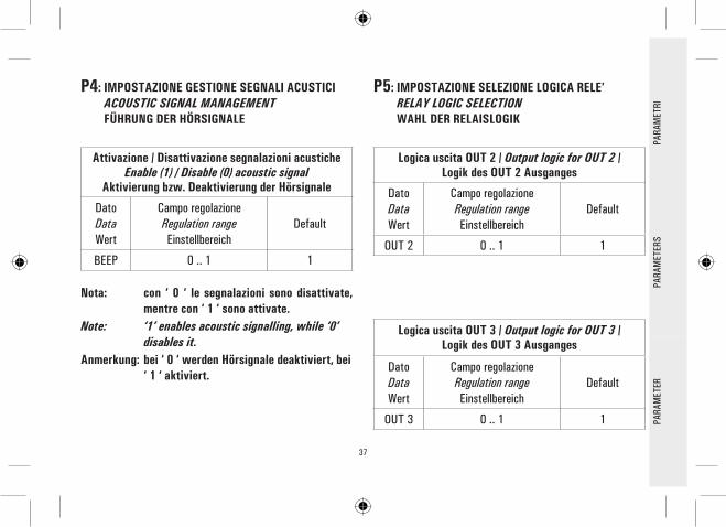
P4: IMPOSTAZIONE GESTIONE SEGNALI ACUSTICI ACOUSTIC SIGNAL MANAGEMENT FÜHRUNG DER HÖRSIGNALE
Attivazione / Disattivazione segnalazioni acusticheEnable (1) / Disable (0) acoustic signal
Aktivierung bzw. Deaktivierung der Hörsignale
DatoDataWert
Campo regolazioneRegulation rangeEinstellbereich
Default
BEEP 0 .. 1 1
Nota: con ‘ 0 ‘ le segnalazioni sono disattivate, mentre con ‘ 1 ‘ sono attivate.
Note: ‘1’ enables acoustic signalling, while ‘0’ disables it.
Anmerkung: bei ‘ 0 ‘ werden Hörsignale deaktiviert, bei ‘ 1 ‘ aktiviert.
P5: IMPOSTAZIONE SELEZIONE LOGICA RELE’ RELAY LOGIC SELECTION WAHL DER RELAISLOGIK
Logica uscita OUT 2 / Output logic for OUT 2 /Logik des OUT 2 Ausganges
DatoDataWert
Campo regolazioneRegulation rangeEinstellbereich
Default
OUT 2 0 .. 1 1
Logica uscita OUT 3 / Output logic for OUT 3 /Logik des OUT 3 Ausganges
DatoDataWert
Campo regolazioneRegulation rangeEinstellbereich
Default
OUT 3 0 .. 1 1 PARA
MET
ERPA
RAM
ETER
SPA
RAM
ETRI

38
Logica uscita OUT 4 / Output logic for OUT 4 /Logik des OUT 4 Ausganges
DatoDataWert
Campo regolazioneRegulation rangeEinstellbereich
Default
OUT 4 0 .. 1 1
Note: Per logica ‘0’ si intende relè NC, mentre per logica ‘1’ si intende relè NA.
Note: ‘1’ means Normally Open (N.O.) logic, while ‘0’ means Normally Closed (N.C.) logic.
Anmerkung: Unter Logik O versteht man NC Relais, unter Logik 1 dagegen NA Relais.
P7: IMPOSTAZIONE TEST CARICHI COLLEGATI LOADS WIRING TEST PRÜFUNG ANGESCHLOSSENE LADUNGEN
Impostazione sequenza testTest sequence cycles number
Einstellung der Prüfungsreihefolge
DatoDataWert
Campo regolazioneRegulation rangeEinstellbereich
Default
TMR 05 .. 25 05
PARA
MET
ERPA
RAM
ETER
SPA
RAM
ETRI
39
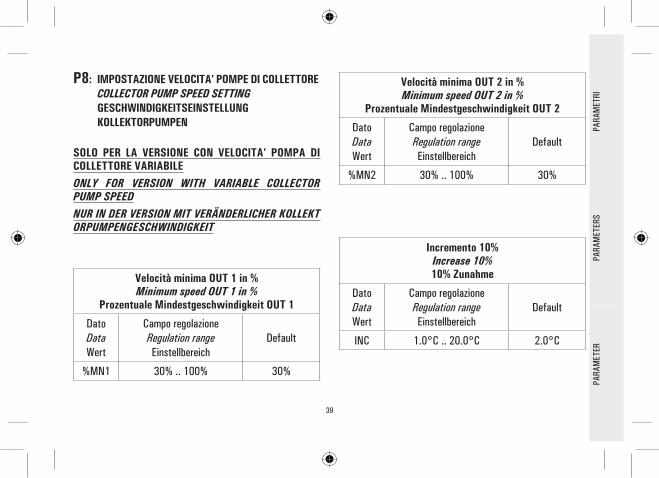
P8: IMPOSTAZIONE VELOCITA’ POMPE DI COLLETTORE COLLECTOR PUMP SPEED SETTING GESCHWINDIGKEITSEINSTELLUNG KOLLEKTORPUMPEN
SOLO PER LA VERSIONE CON VELOCITA’ POMPA DI COLLETTORE VARIABILEONLY FOR VERSION WITH VARIABLE COLLECTOR PUMP SPEEDNUR IN DER VERSION MIT VERÄNDERLICHER KOLLEKTORPUMPENGESCHWINDIGKEIT
Velocità minima OUT 1 in %Minimum speed OUT 1 in %
Prozentuale Mindestgeschwindigkeit OUT 1
DatoDataWert
Campo regolazioneRegulation rangeEinstellbereich
Default
%MN1 30% .. 100% 30%
Velocità minima OUT 2 in %Minimum speed OUT 2 in %
Prozentuale Mindestgeschwindigkeit OUT 2
DatoDataWert
Campo regolazioneRegulation rangeEinstellbereich
Default
%MN2 30% .. 100% 30%
Incremento 10%Increase 10%10% Zunahme
DatoDataWert
Campo regolazioneRegulation rangeEinstellbereich
Default
INC 1.0°C .. 20.0°C 2.0°C
PARA
MET
ERPA
RAM
ETER
SPA
RAM
ETRI

40
Alimentazione 230V~ ±10% 50HzDisplay LCD alfanumerico retroilluminatoGestione di 5 uscite relèPossibilità di configurare la logica di uscita dei relè (normal o reverse)4 ingressi per sonde Pt 1000Range di lettura temperature -40°C .. +260°CCorrezione individuale Offset sonde ±5°CVelocità variabile delle pompe di collettore collegate alle uscite OUT1 e OUT 2, impostabile tramite il parametro P08; solo per la versione con 2 uscite a relè on-off SPST + 2 uscite a relè semiconduttore (velocità pompa collettore variabile)Configurazione di 20 diversi impianti solari; solo per la versione con 4 uscite a relè on-off SPSTConfigurazione di 19 diversi impianti solari; solo per la versione con 2 uscite a relè on-off SPST + 2 uscite a relè semiconduttore (velocità pompa collettore variabile)Visualizzazione grafica degli impianti configuratiDiagnostica on screen (stato ingressi/uscite e messaggi errore)Visualizzazione delle temperature di collettore, boiler e utenzeVisualizzazione della velocità istantanea delle pompe di collettore; solo per la versione con 2 uscite a relè on-off SPST + 2 uscite a relè semiconduttore (velocità pompa collettore variabile)Segnalazione acustica e visiva in caso di guasto e allarmeAttivazione di relè ausiliario in caso di allarmeAutodiagnostica dell’impianto realizzato (funzione test impianto)Configurazione dei parametri installatore protetta da passwordPossibilità attivazione funzione antigeloContabilizzazione ore di integrazioneFunzionamento AUTOMATICO/MANUALE/ABC (Automatic Boiler Control)
••••••••
••
••••
•••••••
CARATTERISTICHE PRINCIPALIDE
UTSC
HEN
GLIS
HIT
ALIA
NO

41
CARATTERISTICHE TECNICHEAlimentazione: 230V~ ±10% 50HzAssorbimento: 4 VATipo di sensori: 4 x Pt1000 Classe B DINLimiti funzionamento sensori: -50°C .. 270°CCampo di lettura temperature: -40,0°C .. 260,0°CPrecisione: ± 1 °CRisoluzione: 0,1 °COffset: su S1: ±5.0°C su S2: ±5.0°C su S3: ±5.0°C su S4: ±5.0°CPassword Installatore: 0000 .. 9999 (default 0000)Segnalazioni Acustiche: On/Off (default On)Spegnimento Back light: 20 sec da ultima pressioneLogica del Relè OUT2: NOR=N.A. REV=N.C. logica non modificabile per schemi con 2 collettori (default N.A.) Logica del Relè OUT3: NOR=N.A. REV=N.C. (default N.A.)Logica del Relè OUT4: NOR=N.A. REV=N.C. (default N.A.)
Portata contatti:Per versione con 4 relè on-off SPST: 4x2(1)A max @ 230V~(SPST) contatti sotto tensionePer versione con 2 relè on-off SPST + 2 relè a semiconduttore: 2x2(1)A max @ 230V~(SPST) 2x2(1)A @ 230V~(45 .. 65 Hz) contatti sotto tensioneGrado di protezione: IP 40Temp. funzionamento: 0°C .. 40°CTemp. stoccaggio: -10°C .. +50°CLimiti umidità: 20% .. 80% RH non condensanteContenitore: Materiale: ABS V0 autoestinguente Colore: Bianco segnale (RAL 9003)Dimensioni: 156 x 108 x 47 (L x A x P)Peso: ~723 gr. (versione con sonde) ~553 gr. (versione senza sonde)Fissaggio: A parete, oppure su asola 144 x 96 mm mediante staffa metallica (Opzionale)
Norme di riferimento EMC: CEI-EN-55014-2 (1997) CEI-EN-55014-1 (2000)Norme di riferimento LVD: CEI-EN-60730-1 (1996) CEI-EN-60730-2-9 (1997)
DEUT
SCH
ENGL
ISH
ITAL
IANO
42
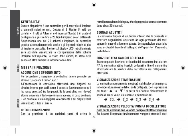
GENERALITA’Questo dispositivo è una centralina per il controllo di impianti a pannelli solari termici. Dotata di 5 Uscite (4 relè dei carichi + 1 relè di Allarme) e 4 Ingressi (Sonde) è in grado di configurare e gestire fino a 20 tipi di impianti solari differenti. Selezionando uno dei 20 schemi d’impianto, la centralina gestirà automaticamente le uscite e gli ingressi relativi al tipo di impianto prescelto. Inoltre sul display LCD retroilluminato sarà possibile visualizzare la configurazione dello schema idraulico dell’impianto, lo stato delle uscite, lo stato delle sonde ed altre numerose informazioni e dati.
MESSA IN FUNZIONEACCENSIONE E SPEGNIMENTOPer accendere o spegnere la centralina tenere premuto per almeno 3 secondi il tasto ‘ esc ‘.All’accensione la centralina effettuerà una diagnosi del circuito interno per verificarne il corretto funzionamento ed il led rosso emetterà tre lampeggii. Se la centralina non rileverà alcuna anomalia il led rosso rimarrà acceso, in caso contrario il led continuerà a lampeggiare velocemente e sul display verrà visualizzato il tipo di errore.
RETROILLUMINAZIONECon la pressione di un qualsiasi tasto si attiva la
retroilluminazione del display che si spegnerà automaticamente dopo circa 20 secondi.
SEGNALI ACUSTICILa centralina dispone di un buzzer interno che le consente di emettere segnalazioni acustiche ad ogni pressione dei tasti oppure in caso di allarme o guasto. Le segnalazioni acustiche sono escludibili tramite il settaggio dell’apposito ‘ Parametro Installatore ‘.
FUNZIONE TEST CARICHI COLLEGATITramite questa funzione, attivabile dal parametro installatore P7, la centralina attiva i carichi collegati al fine di consentire all’installatore la verifica della correttezza dei collegamenti effettuati.
VISUALIZZAZIONE TEMPERATURELa centralina normalmente mostrerà sul display alfanumerico la temperatura rilevata dalle sonde collegate. Con la pressione dei tasti ‘ ‘ o ‘ ‘ si potrà selezionare ciclicamente la sonda di cui si vuole visualizzare la temperatura:
COL S_2 S_3 S_4
VISUALIZZAZIONE VELOCITA’ POMPA DI COLLETTORESolo per la versione con velocità pompa collettore variabileSe durante il normale funzionamento vengono premuti i tasti
DEUT
SCH
ENGL
ISH
ITAL
IANO

43
‘ ‘ o ‘ ‘ la centralina, oltre a visualizzare le temperature rilevate dalle sonde collegate visualizzerà anche la velocità delle pompe di collettore in percentuale.Per quanto riguarda il parametro %FS2, se l’uscita OUT2 non è stata collegata la centralina visualizzerà tale parametro impostato a 0, oppure se lo schema selezionato non prevede l’installazione di una pompa di collettore sull’uscita OUT2 i valori che tale parametro potrà assumere saranno 0 (uscita N.A.) oppure 100 (uscita N.C.), in pratica l’uscita sarà di tipo ON/OFF.
FUNZIONAMENTO AUTOMATICO / MANUALE / ABC (Automatic Boiler Control)La centralina può gestire l’impianto selezionato in 3 differenti modalità:- AUTOMATICO: in questa modalità la centralina gestisce e
controlla automaticamente il funzionamento dell’impianto secondo i dati impostati.
- MANUALE: la pompa del collettore sarà sempre attivata; gli unici controlli attivi saranno quelli relativi alle temperature massime e di sicurezza.
- ABC: la funzione è identica al funzionamento in manuale, tuttavia la pompa del collettore sarà attivata solo se la temperatura sul collettore sarà superiore alla temperatura
‘ T ABC ‘ impostata nell’apposito parametro installatore.
RESETPer effettuare il reset del dispositivo premere il tasto indicato con ‘ RESET ‘ posto sotto lo sportellino removibile; NON USARE AGHI.
PARAMETRI INSTALLATOREPer accedere ai parametri installatore è necessario premere il tasto ‘ ‘.
Immissione PasswordIl display visualizzerà la scritta ‘ PWD 0000 ’ con la prima cifra a sinistra lampeggiante ad indicare la richiesta della password. Per immettere le 4 cifre della password si utilizzano i tasti ‘ ‘ o ‘ ‘; premendo il tasto ‘ ‘ oltre a confermare la cifra inserita, si passerà alla selezione della seconda cifra e così via fino all’ultima. Confermando l’ultima cifra, tramite il tasto ‘ ‘, si accederà ai parametri installatore.La centralina esce dalla fabbrica con la password ‘0000’.
Modifica PasswordSe si desidera variare la password memorizzata, dopo aver premuto il tasto ‘ ‘, procedere come segue:
DEUT
SCH
ENGL
ISH
ITAL
IANO

44
INSERIRE LA PASSWORD ATTUALE.(stessa procedura descritta precedentemente)
IL DISPLAY VISUALIZZA‘ PWDN0000 ‘.
INSERIRE NUOVA PASSWORD.
INSERIRE NUOVA PASSWORD.
LA CENTRALINA MEMORIZZA LA NUOVA PASSWORD E ACCEDE AI PARAMETRI INSTALLATORE.
IL DISPLAY VISUALIZZA‘ PWDC0000 ‘.
PREMERE IL TASTO ‘MENU’.
IL DISPLAY VISUALIZZA
‘ PWDH0000 ‘.
La pressione del tasto ‘ esc ’ farà uscire in qualsiasi momento dalla gestione della password.
Utilizzo parametri installatoreDopo aver immesso la Password esatta si entra nella modalità di modifica dei parametri installatore (icona ‘ SET ’ accesa).La prima informazione fornita è il modello di centralina che si sta utilizzando e il parametro modificabile, ‘ P1 ’.Mediante la pressione dei tasti ‘ ‘ o ‘ ‘ è possibile scorrere tra i vari parametri. Premendo ‘ ‘ si entra in modalità modifica del parametro selezionato. Per uscire dalla modalità installatore premere il tasto ‘ esc ’ oppure attendere 20 secondi.
DEUT
SCH
ENGL
ISH
ITAL
IANO
PREMERE IL TASTO ‘ ‘ DALLASCHERMATA INIZIALE.
45
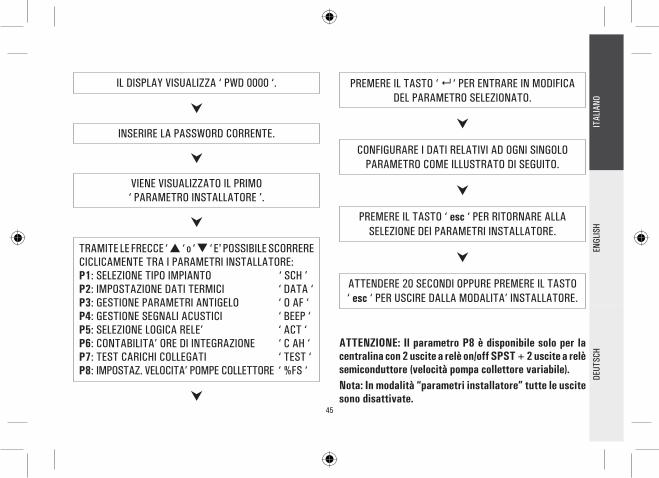
VIENE VISUALIZZATO IL PRIMO‘ PARAMETRO INSTALLATORE ’.
TRAMITE LE FRECCE ‘ ‘ o ‘ ‘ E' POSSIBILE SCORRERE CICLICAMENTE TRA I PARAMETRI INSTALLATORE:P1: SELEZIONE TIPO IMPIANTO ‘ SCH ’P2: IMPOSTAZIONE DATI TERMICI ‘ DATA ‘P3: GESTIONE PARAMETRI ANTIGELO ‘ O AF ‘P4: GESTIONE SEGNALI ACUSTICI ‘ BEEP ‘P5: SELEZIONE LOGICA RELE’ ‘ ACT ‘P6: CONTABILITA’ ORE DI INTEGRAZIONE ‘ C AH ‘P7: TEST CARICHI COLLEGATI ‘ TEST ‘P8: IMPOSTAZ. VELOCITA’ POMPE COLLETTORE ‘ %FS ‘
PREMERE IL TASTO ‘ ‘ PER ENTRARE IN MODIFICA DEL PARAMETRO SELEZIONATO.
CONFIGURARE I DATI RELATIVI AD OGNI SINGOLO PARAMETRO COME ILLUSTRATO DI SEGUITO.
IL DISPLAY VISUALIZZA ‘ PWD 0000 ‘.
INSERIRE LA PASSWORD CORRENTE.
DEUT
SCH
ENGL
ISH
ITAL
IANO
PREMERE IL TASTO ‘ esc ‘ PER RITORNARE ALLA SELEZIONE DEI PARAMETRI INSTALLATORE.
ATTENDERE 20 SECONDI OPPURE PREMERE IL TASTO ‘ esc ‘ PER USCIRE DALLA MODALITA’ INSTALLATORE.
ATTENZIONE: Il parametro P8 è disponibile solo per la centralina con 2 uscite a relè on/off SPST + 2 uscite a relè semiconduttore (velocità pompa collettore variabile).Nota: In modalità “parametri installatore” tutte le uscite sono disattivate.

46
SELEZIONATO IL PARAMETRO P2 PREMEREIL TASTO ‘ ‘.
P1: SELEZIONE TIPO IMPIANTOMediante la pressione dei tasti ‘ ‘ o ‘ ‘ verranno mostrati tutti gli impianti realizzabili (se per l’impianto selezionato una delle sonde presenta un problema o non è collegata, tale sonda lampeggerà sul display).Per confermare l’impianto voluto premere il tasto ‘ ‘; la centralina memorizzerà la scelta e tornerà a mostrare l’elenco dei parametri. Per annullare la selezione premere il tasto ‘ esc ’, in questo caso la centralina abbandonerà la modifica effettuata e tornerà a mostrare l’elenco dei parametri.Nel capitolo ‘ SCHEMA ‘ vengono elencati i parametri che influenzano la regolazione delllo schema selezionato e potranno essere modificati tramite il secondo parametro installatore.
P2: IMPOSTAZIONE DATI TERMICITramite questo parametro si possono impostare i dati termici relativi all’impianto selezionato:La centralina viene fornita con i dati termici preimpostati per un funzionamento ottimale. La modifica di tali valori deve essere effettuata da personale qualificato.
DEUT
SCH
ENGL
ISH
ITAL
IANO
TRAMITE LE FRECCE ‘ ‘ o ‘ ‘ E' POSSIBILE SCORRERE CICLICAMENTE TRA I DATI TERMICI:- Temperature di sicurezza- Differenziali- Isteresi dei differenziali- Isteresi dei termostati di sicurezza- Isteresi dei termostati- Offset- Temperature massime- Temperatura di integrazione- Temperatura di ABC (controllo automatico del boiler)
PREMERE IL TASTO ‘ ‘ PER ENTRARE IN MODIFICA DEL DATO TERMICO SELEZIONATO; IL DATO COMINCIA
A LAMPEGGIARE.
IMPOSTARE IL VALORE NUMERICO DESIDERATO TRAMITE LE FRECCE ‘ ‘ o ‘ ‘.

47
PREMERE IL TASTO ‘ ‘ PER CONFERMARE L’IMPOSTAZIONE EFFETTUATA OPPURE PREMERE IL
TASTO ‘ esc ’ PER ANNULLARE LA MODIFICA.
DEUT
SCH
ENGL
ISH
ITAL
IANO
SELEZIONATO IL PARAMETRO P3 PREMERE IL TASTO ‘ ‘.
Nel capitolo ‘ PARAMETRI ‘ sono elencati i campi di regolazione relativi ad ogni singolo dato.
P3: GESTIONE PARAMETRI ANTIGELOTramite questo parametro si possono impostare i dati per gestire la funzione di antigelo.
La centralina viene fornita con i dati di antigelo preimpostati per un funzionamento ottimale.La modifica di tali valori deve essere effettuata da personale qualificato.
E' POSSIBILE SCORRERE CICLICAMENTE TRA I DATI DI ANTIGELO TRAMITE LE FRECCE ‘ ‘ o ‘ ‘:- Temperature di antigelo ‘ TAF ’- Intervallo di accensione pompa del collettore ‘ P ON ‘- Intervallo di spegnimento pompa del collettore ‘ P OFF ‘- Durata del Test di antigelo ‘ TMR ‘
PREMERE IL TASTO ‘ ‘ PER ENTRARE IN MODIFICA DEL DATO TERMICO SELEZIONATO; IL DATO COMINCIA
A LAMPEGGIARE.
TRAMITE LE FRECCE ‘ ‘ o ‘ ‘, IMPOSTARE IL VALORE NUMERICO DESIDERATO.
PREMERE IL TASTO ‘ ‘ PER CONFERMARE L’IMPOSTAZIONE EFFETTUATA OPPURE PREMERE IL
TASTO ‘ esc ’ PER ANNULLARE LA MODIFICA.

48
Nel capitolo ‘ PARAMETRI ‘ elenchiamo il dettaglio dei dati e i relativi campi di regolazione.
P4: GESTIONE SEGNALI ACUSTICITramite questo parametro è possibile attivare o disattivare le segnalazioni acustiche della centralina (toni tastiera, allarmi e diagnostica).
Nel capitolo ‘ PARAMETRI ‘ elenchiamo il dettaglio dei dati e i relativi campi di regolazione.
P5: SELEZIONE LOGICA RELE’Tramite questo parametro è possibile invertire la logica di comando dei relè, ovvero trasformare l’uscita da Normalmente Aperta (N.A.) a Normalmente Chiusa (N.C.) e viceversa.Sarà possibile modificare solamente la logica delle uscite che lo schema selezionato prevede come attive.Variando lo schema mediante il parametro 1 tutte le logiche delle uscite saranno reimpostate al valore N.A. (default).
PREMENDO ‘ ‘ DOPO AVER MODIFICATO IL DATO RELATIVO ALLA DURATA DEL TEST DI ANTIGELO, LA
CENTRALINA CONFERMA IL DATO ED ESEGUE IL TEST DI ANTIGELO .
Le uscite di cui è possibile modificare la logica sono al massimo 3 e sono elencate nel paragrafo ‘ PARAMETRI ‘.
SELEZIONATO IL PARAMETRO P5 PREMERE IL TASTO ‘ ‘.
TRAMITE LE FRECCE ‘ ‘ o ‘ ‘, E’ POSSIBILE SCORRERE LE USCITE ATTIVE.
SELEZIONARE L’USCITA INTERESSATA E PREMERE IL TASTO ‘ ‘.
VARIARE LA LOGICA DELL’USCITA TRAMITELE FRECCE ‘ ‘ o ‘ ‘.
PREMERE IL TASTO ‘ ‘ PER CONFERMARE L’IMPOSTAZIONE EFFETTUATA OPPURE PREMERE IL
TASTO ‘ esc ’ PER ANNULLARE LA MODIFICA.
DEUT
SCH
ENGL
ISH
ITAL
IANO

49
PREMERE ‘ ‘, IL DISPLAY VISUALIZZA ‘H’ LAMPEGGIANTE.
PREMENDO ‘ ‘ SI AZZERA IL CONTATORE, PREMENDO INVECE ‘ esc ’ SI TORNA ALLA VISUALIZZAZIONE DELLE ORE CORRENTI .
SELEZIONATO IL PARAMETRO P7 PREMERE IL TASTO ‘ ‘.
IL DISPLAY VISUALIZZA ‘ TMR ’ E IL NUMERO DI CICLI
DEL TEST.
Il conteggio delle ore di attivazione dell’integrazione è compresa tra 0000 .. 9999. Raggiunto il valore massimo, il conteggio si arresterà.
P7: TEST CARICHI COLLEGATITramite questo parametro si può effettuare il test funzionale dei carichi collegati alla centralina.La centralina verifica i carichi collegati, a seconda dello schema configurato, attivando tutte le uscite disponibili in sequenza per 10 secondi ciascuna.La sequenza del test, a multipli di 5, è impostabile tramite l’unico parametro presente ‘ TMR ‘.L’attivazione del test sarà segnalato sul display con l’accensione dell’icona ‘ TIMER ‘.
SELEZIONATO IL PARAMETRO P6 PREMERE IL TASTO ‘ ‘.
IL DISPLAY VISUALIZZA ‘ H ’ E LE ORE DI EFFETTIVA
ATTIVAZIONE DELLA FONTE DI INTEGRAZIONE.
DEUT
SCH
ENGL
ISH
ITAL
IANO
P6: CONTABILITA’ ORE DI INTEGRAZIONEMediante questo parametro è possibile visualizzare e azzerare le ore di effettiva attivazione della fonte di integrazione.
PREMERE ‘ ‘, IL DISPLAY VISUALIZZA ‘TMR’ LAMPEGGIANTE.

50
di diminuire il tempo di transito del fluido nel collettore, ovvero aumentare la velocità del fluido in transito e quindi aumentare il numero di giri della pompa di collettore.Tramite il parametro P8 è possibile impostare la velocità minima di funzionamento delle pompe di collettore, in %, e la variazione di temperatura rispetto al T necessaria per avere un incremento della velocità delle pompe di collettore del 10% (parametro INC).
La centralina viene fornita con i dati preimpostati per un funzionamento ottimale. La modifica di tali valori deve essere effettuata da personale qualificato.
TRAMITE I TASTI ‘ ‘ o ‘ ‘ E’ POSSIBILE VARIARE IL NUMERO DI CICLI 5, 10, 15, 20, 25.
PREMENDO ‘ ‘ SI CONFERMA IL DATO IMPOSTATO E
SI AVVIA IL TEST DEI CARICHI.INVECE, PREMENDO ‘ esc ’ SI ANNULLA LA MODIFICA E SI TORNA ALLA VISUALIZZAZXIONE DEL NUMERO DI
CICLI PREIMPOSTATI.
P8: IMPOSTAZIONE VELOCITA’ POMPE DI COLLETTORESolo per la versione con velocità pompa collettore variabileTramite questo parametro, selezionabile tramite il tasto ‘menu’, è possibile impostare i dati che andranno a gestire la velocità delle pompe di collettore collegate alle uscite OUT1 e OUT2.
Il principio di funzionamento che regola la variazione della velocità delle pompe di collettore è legato all’esigenza di mantenere il più costante possibile la differenza di temperatura tra il collettore solare e il boiler (T).Essendo noto che all’aumentare della radiazione solare incidente, il T tende ad aumentare, un modo che consente di abbassare il T a parità di radiazione solare incidente è quello
SELEZIONATO IL PARAMETRO P8 PREMERE IL TASTO ‘ ‘.
DEUT
SCH
ENGL
ISH
ITAL
IANO
TRAMITE LE FRECCE ‘ ‘ o ‘ ‘ E' POSSIBILE SCORRERE CICLICAMENTE TRA I PARAMETRI POMPA COLLETTORE:VELOCITA’ MINIMA OUT 1 IN % ‘ %MN1 30 ‘VELOCITA’ MINIMA OUT 2 IN % ‘ %MN2 30 ‘INCREMENTO 10% ‘ INC 2.0°C ‘
51
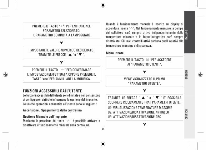
FUNZIONI ACCESSIBILI DALL’UTENTELe funzioni accessibili dall’utente sono limitate e non consentono di configurare i dati che influenzano la gestione dell’impianto.Le uniche operazioni consentite all’utente sono le seguenti:
Accensione / Spegnimento della centralina
Gestione Manuale dell’impiantoMediante la pressione del tasto ‘ ‘ è possibile attivare o disattivare il funzionamento manuale della centralina.
PREMERE IL TASTO ‘ ‘ PER ACCEDEREAI ‘ PARAMETRI UTENTI ’.
PREMERE IL TASTO ‘ ‘ PER ENTRARE NEL PARAMETRO SELEZIONATO;
IL PARAMETRO COMINCIA A LAMPEGGIARE
IMPOSTARE IL VALORE NUMERICO DESIDERATO TRAMITE LE FRECCE ‘ ‘ o ‘ ‘.
PREMERE IL TASTO ‘ ‘ PER CONFERMARE L’IMPOSTAZIONEEFFETTUATA OPPURE PREMERE IL
TASTO ‘esc’ PER ANNULLARE LA MODIFICA.
DEUT
SCH
ENGL
ISH
ITAL
IANO
Quando il funzionamento manuale è inserito sul display si accenderà l’icona ‘ ‘. Nel funzionamento manuale la pompa del collettore sarà sempre attiva indipendentemente dalle temperature misurate e la fonte integrativa sarà sempre disattivata. Gli unici controlli attivi saranno quelli relativi alle temperature massime e di sicurezza.
Menu utente
VIENE VISUALIZZATO IL PRIMO‘ PARAMETRO UTENTE ’.
TRAMITE LE FRECCE ‘ ‘ o ‘ ‘ E' POSSIBILE SCORRERE CICLICAMENTE TRA I PARAMETRI UTENTE:U1: VISUALIZZAZIONE TEMPERATURE MASSIMEU2: ATTIVAZIONE/DISATTIVAZIONE ANTIGELOU3: ATTIVAZIONE/DISATTIVAZIONE ABC

52
PREMERE IL TASTO ‘ ‘ PER ENTRARE NEL PARAMETRO SELEZIONATO.
IMPOSTARE I DATI RELATIVI AD OGNI SINGOLO PARAMETRO COME ILLUSTRATO DI SEGUITO.
PREMERE IL TASTO ‘ esc ‘ PER RITORNARE ALLA
SELEZIONE DEI PARAMETRI UTENTE.
ATTENDERE 20 SECONDI OPPURE PREMERE IL TASTO
‘ esc ‘ PER USCIRE DALLA MODALITA’ UTENTE.
ATTENZIONE!in modalità ‘PARAMETRI UTENTE‘ tutte le uscite sono disattivate.
Visualizzazione Temperature Massime RegistrateIl parametro ‘ TMAX U1 ‘ permette di visualizzare la temperatura massima registrata nel sistema da ciascuna sonda TM-.
PREMERE IL TASTO ‘ ‘ PER ACCEDEREALLA VISUALIZZAZIONE DELLE TEMPERATURE.
TRAMITE LE FRECCE ‘ ‘ o ‘ ‘ E’ POSSIBILE SCORRERE CICLICAMENTE TRA LE TEMPERATURE RILEVATE:
TM1 TM2 TM3 TM4
DEUT
SCH
ENGL
ISH
ITAL
IANO
PREMERE IL TASTO ‘ ‘, IL DISPLAY VISUALIZZA IL NUMERO DELLA SONDA LAMPEGGIANTE.
INVECE PREMENDO IL TASTO ‘ esc ‘ SI RITORNA ALLA VISUALIZZAZIONE DEI PARAMETRI UTENTE.
PREMENDO ‘ ‘ SI AZZERA LA TEMPERATURA FINORA REGISTRATA; PREMENDO INVECE
‘ esc ’ SI TORNA ALLA VISUALIZZAZIONE DELLA TEMPERATURA MEMORIZZATA.

53
Attivazione dell’AntigeloIl parametro ‘ AFR U2 ‘ (anti frost) permette di attivare o disattivare la funzione di antigelo. La gestione dei dati di antigelo si effettua tramite i parametri utente.
PREMERE IL TASTO ‘ esc ‘ PER USCIRE DALLA VISUALIZZAZIONE DELLA TEMPERATURA MASSIMA.
DEUT
SCH
ENGL
ISH
ITAL
IANO
PREMERE IL TASTO ‘ ‘;IL DISPLAY VISUALIZZA ‘AFR ‘ LAMPEGGIANTE.
TRAMITE LE FRECCE ‘ ‘ o ‘ ‘ E' POSSIBILE ATTIVARE OPPURE DISATTIVARE L’ANTIGELO:0: DISATTIVO1: ATTIVO (IL DISPLAY VISUALIZZA )
Controllo automatico del Boiler tramite i Collettori (ABC)La funzione ‘ ABC U3 ‘ (Automatic Boiler Control) aggiunge una interessante funzionalità al modo Manuale. Se la funzione ‘ ABC ‘ è attivata, la pompa del collettore, al contrario del modo Manuale in cui è sempre attiva, viene bloccata se la temperatura sul collettore, misurata tramite la sonda S1, scende al di sotto della temperatura impostata tramite il parametro ‘ TABC ‘ impostato mediante i parametri installatore.
PREMERE IL TASTO ‘ ‘ PER CONFERMARE L’IMPOSTAZIONE OPPURE PREMERE IL TASTO ‘ esc ‘
PER USCIRE DAI PARAMETRI UTENTE.
PREMERE IL TASTO ‘ ‘;IL DISPLAY VISUALIZZA ‘ABC ‘ LAMPEGGIANTE.
PREMERE IL TASTO ‘ ‘ PER CONFERMARE L’IMPOSTAZIONE OPPURE PREMERE IL TASTO‘ esc ‘ PER USCIRE DAI PARAMETRI UTENTE.
TRAMITE LE FRECCE ‘ ‘ o ‘ ‘ E' POSSIBILE ATTIVARE OPPURE DISATTIVARE L’ABC:0: DISATTIVO1: ATTIVO (IL DISPLAY VISUALIZZA e )

54
ANOMALIA PROBABILE CAUSA
Durante il normale funzionamento la centralina visualizza sul display il simbolo ed emette una segnalazione acustica caratterizzata da una serie di ‘beep’.La sonda che ha generato il problema lampeggia.
La centralina ha rilevato un’anomalia sulle sonde.Verrà visualizzato il numero della sonda in avaria e verrà indicato il tipo di anomalia presente.
Il display visualizza l’icona e la centralina emette una segnalazione acustica caratterizzata da una serie di ‘beep’.
Una o più sonde hanno rilevato una temperatura maggiore della relativa temperatura di sicurezza impostata.
Nella selezione dell’impianto da realizzare (parametro installatore P1) lampeggiano una o più sonde.
La sonda non è stata collegata o è in avaria.
GESTIONE ANOMALIE E PROBABILI CAUSE
Sonda in corto circuito (R≈0).COL ShrTS_2 ShrTS_3 ShrTS_4 ShrT
Sonda aperta (R=∞).COL OPEnS_2 OPEnS_3 OPEnS_4 OPEn
DEUT
SCH
ENGL
ISH
ITAL
IANO

55
Power supply 230V~ ±10% 50HzBacklit alphanumeric LCD displayManagement of 5 output relaysPossibility of setting up the output logic of the relays (normal or reversed)4 inputs for Pt 1000 probesTemperature range readings from -40°C to +260°CIndividual probe offset correction ±5°CVariable speed of collector pumps connected to outputs OUT1 and OUT 2, may be set via parameter P08; only for version with 2 SPST on-off relay outputs + 2 semiconductor relay outputs (variable collector pump speed)Configuration of 20 different solar heating systems; only for version with 4 SPST on-off relay outputsConfiguration of 19 different solar heating systems; only for version with 2 SPST on-off relay outputs + 2 semiconductor relay outputs (variable collector pump speed)Graphical visualization of the configured installationOn screen diagnostic (input/output state and error messages)Visualization of the collector, boiler and additional devices temperaturesDisplay of instantaneous collector pump speed; only for version with 2 SPST on-off relay outputs + 2 semiconductor relay outputs (variable collector pump speed)Acoustic and visual signal in case of failure and alarmActivation of an auxiliary relay in case of an alarmSelf-diagnosis of the actual installation (installation function test)Password-protected configuration for installer parametersPossibility of antifrost function activationHeat integration hours counterAUTOMATIC / MANUAL / ABC (Automatic Boiler Control) operation
••••••••
••
••••
•••••••
MAIN FEATURES
DEUT
SCH
ENGL
ISH
ITAL
IANO

56
TECHNICAL FEATURESPower supply: 230V~ ±10% 50HzPower absorption: 4 VASensors type: 4 x Pt1000 Class B DINSensor operating range: -50°C .. 270°CTemperature reading range: -40,0°C .. 260,0°CAccuracy: ± 1 °CResolution: 0,1 °COffset adjustment: on S1: ±5.0°C on S2: ±5.0°C on S3: ±5.0°C on S4: ±5.0°CInstaller Password: 0000 .. 9999 (default 0000)Acoustic Signal: On/Off (default On)Backlight timing: 20 sec from last keypressOUT2 Relay Logic: NOR=N.O. REV=N.C. non-editable logic for layouts with 2 collectors (default N.O.)OUT3 Relay Logic: NOR=N.O. REV=N.C. (default N.O.)OUT4 Relay Logic: NOR=N.O. REV=N.C. (default N.O.)
Contacts rating:For version with 4 SPST on-off relays: 4x2(1)A max @ 230V~(SPST) Contacts powered.For version with 2 SPST on-off relays + 2 semiconductor relays: 2x2(1)A max @ 230V~(SPST) 2x2(1)A @ 230V~(45 .. 65 Hz) Contacts powered.Protection grade: IP 40Operating temp. range: 0°C .. 40°CStorage temp. range: -10°C .. +50°CHumidity limits: 20% .. 80% RH non-condensingCase: Material: ABS V0 self-extinguishing Color: Signal White (RAL 9003)Dimensions: 156 x 108 x 47 (W x H x D)Weight: ~723 gr. (version with probe) ~553 gr. (version without probe)Installation: Wall-mount or panel-mount on a 144 x 96 mm hole by means of the proper metal fitting (optional)
EMC normative references: CEI-EN-55014-2 (1997) CEI-EN-55014-1 (2000)LVD normative references: CEI-EN-60730-1 (1996) CEI-EN-60730-2-9 (1997)
DEUT
SCH
ENGL
ISH
ITAL
IANO

57
OVERVIEWThis device is a centralized control unit for thermal solar panels. Supplied with 5 outputs (Load Relays + Alarm Relays) and 4 Inputs (Probes) it is able to manage a system configuration that can be selected among 20 common types of layouts. When a specific installation is selected, the control unit automatically manages the outputs and inputs used to control the valves, the pumps, the integrative sources and the probes used in the type of installation selected.Moreover on the backlit LCD display it is possible to visualize the hydraulic diagram of the installation set up, the state of the outputs, the probes as well as several other data and informations.
STARTINGTURNING ON AND OFFTo turn the control unit on and off, press the ‘ esc ’ key for at least 3 seconds. When the control unit is turned on it will carry out a diagnosis of the internal circuitry to verify its correct operation and the red led will flash three times.If the control unit reveals no anomalies the red led will remain on, otherwise it will continue to flash quickly and the display will show the type of error.
BACKLIGHTBy pressing any key the backlight of the display is activated. The backlight automatically shuts off after about 20 seconds from the last key depressure.
ACOUSTIC SIGNALSThe control unit is supplied with an internal buzzer that gives the user an acoustic feedback in case of pressure on the keys, alarms and failure. The acoustic signal can be disabled by properly setting the relevant ‘ Installer Parameter ’.
TEST FUNCTION FOR LOAD WIRINGS CHECKThrough this function, available at the Installer Parameter P7, the control unit cyclically activates the loads wired to the unit so that the installer can verify the accuracy of the wirings performed.
DISPLAYING THE TEMPERATUREDuring normal operation the control unit alphanumeric display will show the temperatures measured by the probes connected to it. By pressing the ‘ ‘ or ‘ ‘ keys it is possible to cyclically choose which probe temperature will be shown on the display:
COL S_2 S_3 S_4
DEUT
SCH
ENGL
ISH
ITAL
IANO

58
DISPLAY OF COLLECTOR PUMP SPEEDOnly for version with variable collector pump speedIf the ‘ ‘ or ‘ ‘ keys are pressed during normal operation, the central unit will not only show the temperature as read by the connected probes but it will also display the solar collector pump speed as a percentage.As regards the %FS2 parameter, the power unit will show this parameter set at 0 if the OUT2 outlet is not connected.Alternatively, if the selected installation diagram does not require installation of a collector pump at outlet OUT2, this parameter will only be displayed with the values 0 (outlet N.0.) or 100 (outlet N.C.), i.e. it will work as an ON /OFF type outlet.
AUTOMATIC / MANUAL / ABC (Automatic Boiler Control) OPERATIONThe control unit can manage the installation selected in 3 different modes:
- AUTOMATIC: in this mode the control unit automatically manages and controls the operation of the installation according to the programmed data.
- MANUAL: the collector pump is continuously powered; the only active controls will be those related
to the maximum temperature and safety.
- ABC: this mode is identical to the Manual mode except that the collector pump will be activated only when the temperature of the collector exceeds ‘ T ABC ’ programmed in the relevant installer parameter.
RESETIn order to reset the device, press the key labelled as ‘ RESET ’ located behind the removable door; DO NOT USE PINS OR NEEDLES.
INSTALLER PARAMETERSTo access the installer parameters press the ‘ ‘ key.
Entering the PasswordThe display will show ‘PWD 0000’ with the leftmost digit flashing thus requesting for the correct password.In order to set the 4 password digits use the ‘ ‘ or ‘ ‘ key; by pressing the ‘ ‘ key, the current digit is confirmed and the flashing is transferred to the following digit.After confirming the last digit, the ‘ ‘ key will give access to the installer parameters.The initial password is factory set as ‘0000’.
DEUT
SCH
ENGL
ISH
ITAL
IANO

59
ENTER THE CURRENT PASSWORD.(same procedure described above)
THE DISPLAY SHOWS‘ PWDN0000 ’.
INSERT THE NEW PASSWORD.
THE DISPLAY SHOWS‘ PWDC0000 ‘.
INSERT NEW PASSWORD.
THE CONTROL UNIT WILL MEMORIZETHE NEW PASSWORD AND GIVE ACCESS
TO THE INSTALLER PARAMETERS.
Pressing the ‘ esc ’ key at any time will exit the password management mode. DE
UTSC
HEN
GLIS
HIT
ALIA
NO
PRESS THE ‘ MENU ’ KEY.
THE DISPLAY SHOWS‘ PWDH0000 ’.
Modifying the PasswordIn order to modify the stored password, first press the ‘ ‘ key, then proceed as follows:

60
INSERT THE CURRENT PASSWORD.
THE DISPLAY SHOWS THE FIRST‘ INSTALLER PARAMETER ’.
USING THE ARROWS ‘ ‘ OR ‘ ‘ IT IS POSSIBLE TO CYCLICALLY SCROLL THROUGH THE INSTALLATION PARAMETERS:P1: SELECTION INSTALLATION TYPE ‘ SCH ’P2: SETTING THERMAL DATA ‘ DATA ’P3: ANTIFROST PARAMETERS MANAGEMENT ‘ O AF ’P4: ACOUSTIC SIGNAL MANAGEMENT ‘ BEEP ’P5: LOGIC RELAY SELECTION ‘ ACT ’P6: INTEGRATION HOURS COUNTER ‘ C AH ’P7: LOADS WIRING TEST ‘ TEST ’P8: SETTING OF COLLECTOR PUMP SPEED ‘ %FS ‘
Using installer parametersInserting the correct Password gives access to the installer parameters change mode (‘ SET ’ icon lights). The first information displayed is the model of the control unit in use and the parameter ‘ P1 ’ value.By pressing the ‘ ‘ or ‘ ‘ keys it is possible to scroll through the various parameters. Pressing the ‘ ‘ key takes the user to the parameter modifying mode selected.To exit the installer mode press the ‘ esc ’ key or wait 20 seconds.
DEUT
SCH
ENGL
ISH
ITAL
IANO
PRESS THE ‘ ‘ KEY ON THE START PAGE.
THE DISPLAY SHOWS ‘ PWD 0000 ‘.
PRESS THE ‘ ‘ KEY TO MODIFY THE
SELECTED PARAMETER.

61
AFTER SELECTING PARAMETER P2 PRESSTHE ‘ ‘ KEY.
P1: SELECT INSTALLATION TYPEPressing the ‘ ‘ or ‘ ‘ keys will show all the installations that can be set up (if the probe for the selected installation has a problem or is left unconnected, that probe will flash on
DEUT
SCH
ENGL
ISH
ITAL
IANO
PRESS THE ‘ esc ’ KEY TO RETURN TO THE INSTALLER PARAMETERS SELECTION.
WAIT 20 SECONDS OR PRESS THE ‘ esc ’ KEY TO EXIT THE INSTALLER MODE.
WARNING: Parameter P8 is available only for the controller with 2 SPST relay outputs + 2 semiconductor relay outputs (variable collector pump speed).Note: In the ‘ installer parameters ‘ mode all the outputs are disabled.
the display).To confirm the selected installation press the ‘ ‘ key; the control unit will memorize the choice and the display will again show the parameter list.To cancel the selection, press the ‘ esc ’ key. In this case the control unit will abandon the changes made and will show again the parameter list.
The parameters influencing the regulation of the selected setup are listed in the annex ‘ DIAGRAM ‘ and can be modified through the second installer parameter (P2).
P2: SETTING THE THERMAL DATAUsing this parameter it is possible to set the thermal data related to the selected installation:The control unit is supplied with pre-programmed thermal data for optimal operation. Any change to these values must be performed by qualified personnel only.
CONFIGURE DATA FOR EVERY SINGLE PARAMETER AS EXPLAINED BELOW.

62
USING THE ‘ OR ‘ ‘ ARROWS IT IS POSSIBLE TO SCROLL CYCLICALLY THROUGH THE THERMAL DATA:- Safety temperatures- Differentials- Hysteresis of the differentials- Hysteresis of the safety thermostats- Hysteresis of the thermostats- Offset- Maximum temperatures- Integration temperature- ABC (Automatic Boiler Control) temperature
PRESS THE ‘ ‘ TO MODIFY THE THERMAL DATA SELECTED; THE DATA WILL START FLASHING.
SET THE DESIRED NUMERIC VALUE USINGTHE ‘ ‘ OR ‘ ‘ ARROWS.
PRESS THE ‘ ‘ KEY TO CONFIRM THE PROGRAMMED SETTINGS OR PRESS THE ‘ esc ’ KEY TO CANCEL THE
CHANGES.
A list of the allowed regulation ranges for every single value is given in the annex ‘ PARAMETERS ‘.
P3: ANTIFROST PARAMETER MANAGEMENTUsing this parameter it is possible to set the data managing the antifrost function.The control unit is supplied with preset antifrost data for optimal operation.Any change to these values must be performed by qualified personnel only.
AFTER SELECTING PARAMETER P3 PRESSTHE ‘ ‘ KEY.
DEUT
SCH
ENGL
ISH
ITAL
IANO
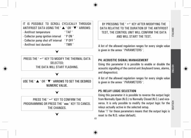
63
PRESS THE ‘ ‘ KEY TO MODIFY THE THERMAL DATA SELECTED;
THE DATA WILL START FLASHING.
USE THE ‘ ‘ OR ‘ ‘ ARROWS TO SET THE DESIRED NUMERIC VALUE.
PRESS THE ‘ ‘ KEY TO CONFIRM THE PROGRAMMING OR PRESS THE ‘ esc ’ KEY TO CANCEL
THE CHANGES.
BY PRESSING THE ‘ ‘ KEY AFTER MODIFYING THE DATA RELATIVE TO THE DURATION OF THE ANTIFROST
TEST, THE CONTROL UNIT WILL CONFIRM THE DATA AND WILL START THE TEST.
A list of the allowed regulation ranges for every single value is given in the annex ‘ PARAMETERS ‘.
P4: ACOUSTIC SIGNAL MANAGEMENTUsing this parameter it is possible to enable or disable the acoustic signalling of the control unit (keyboard tones, alarms, and diagnostics).
A list of the allowed regulation ranges for every single value is given in the annex ‘ PARAMETERS ‘.
P5: RELAY LOGIC SELECTIONUsing this parameter it is possible to reverse the output logic from Normally Open (N.O.) to Normally Closed (N.C.) and vice- versa. It is only possible to modify the output logic for the relays actually active in the selected setup.Value ‘1’ for these parameters means that the output logic is reset to the N.O. value (default).
IT IS POSSIBLE TO SCROLL CYCLICALLY THROUGH ANTIFROST DATA USING THE ‘ ‘ OR ‘ ‘ ARROWS:- Antifrost temperature ‘ TAF ’ - Collector pump ignition interval ‘ P ON ’ - Collector pump shut off interval ‘ P OFF ’ - Antifrost test duration ‘ TMR ’
DEUT
SCH
ENGL
ISH
ITAL
IANO

64
SELECT THE DESIRED OUTPUT ANDPRESS THE ‘ ‘ KEY.
PRESS THE ‘ ‘ KEY TO CONFIRM THE PROGRAMMED SETTING OR PRESS THE ‘ esc ’ KEY TO CANCEL THE
MODIFICATION.
CHANGE THE OUTPUT LOGIC USINGTHE ‘ ‘ OR ‘ ‘ ARROWS.
The user is allowed to select the relay logic for max. 3 outputs only.
The counter recording the running hours of the integrative source can handle values up to 9999. Once the maximum value is reached the counter stops.
AFTER SELECTING PARAMETER P6 PRESS THE ‘ ‘ KEY.
THE DISPLAY SHOWS ‘H’ AND ACTUAL HOURS OF ACTIVITY OF THE INTEGRATIVE SOURCE.
PRESS THE ‘ ‘ KEY , THE DISPLAYSHOWS ‘H’ FLASHING.
PRESSING THE ‘ ‘ KEY RESETS THE COUNTER, PRESSING THE ‘ esc ’ AGAIN SHOWS THE CURRENT
RUNNING HOURS.
AFTER SELECTING PARAMETER P5 PRESSTHE ‘ ‘ KEY.
USING THE ‘ ‘ OR ‘ ‘ ARROWS IT IS POSSIBLE TO
SCROLL THROUGH THE ACTIVE OUTPUTS.
P6: INTEGRATION HOURS COUNTERUsing this parameter it is possible to display the actual number of hours of the integrative source operation or reset it.
DEUT
SCH
ENGL
ISH
ITAL
IANO

65
AFTER SELECTING PARAMETER P7 PRESSTHE ‘ ‘ KEY.
THE DISPLAY SHOWS ‘ TMR ’ AND THE NUMBER OF CYCLES IN THE TEST.
PRESS ‘ ‘. THE DISPLAYSHOWS ‘TMR’ FLASHING.
P7: LOADS WIRING TESTThis parameter allows to set the test of the loads wired to the control unit as well as the wirings themselves.The control unit tests the loads connected to it, according to the selected diagram, by turning on all the available outputs in sequence for 10 seconds each.The number of times for which the entire test is repeated, in multiples of 5, can be set using the single ‘ TMR ’ parameter present. The activation of the test is signalled on the display with the ‘ TIMER ’ icon.
PRESS ‘ ‘ TO CONFIRM THE PROGRAMMED DATA AND START THE TEST. BY PRESSING ‘ esc ’ THE
MODIFICATIONS ARE CANCELED AND THE DISPLAY AGAIN SHOWS THE NUMBER OF PRESET CYCLES.
USING THE KEYS ‘ ‘ OR ‘ ‘ SET THE NUMBER OF CYCLES TO 5, 10, 15, 20 OR 25.
P8: SETTING OF COLLECTOR PUMP SPEEDOnly for version with variable collector pump speedThis parameter can be selected by the ‘menu’ key, and permits to set the data which will control the speed of the collector pumps connected to OUT1 and OUT2.
The working principle which regulates solar collector pump speed variation is very much linked to the need to keep the difference in temperature between the solar collector and the boiler as constant as possible (T).Since it is a well-known fact that as incidental solar radiation increases, the T also tends to increase, one way of decreasing the T whilst maintaining incidental solar radiation constant is to reduce the amount of time that the fluid transits within
DEUT
SCH
ENGL
ISH
ITAL
IANO

66
FUNCTIONS ACCESSIBLE TO THE USERThe functions accessible to the user are limited and do not allow setting those data influencing the installation management. The only operations allowed to the user are the following:
AFTER SELECTING THE P8 PARAMETER, PRESS ‘ ‘.
PRESS ARROWS ‘ ‘ AND ‘ ‘ TO CYCLICALLY SCROLL COLLECTOR PUMP PARAMETERS:MINIMUM SPEED OUT 1 IN % ‘ %MN1 30 ‘MINIMUM SPEED OUT 2 IN % ‘ %MN2 30 ‘INCREASE 10% ‘ INC 2.0°C ‘
PRESS ‘ ‘ TO CHANGE THE SELECTED PARAMETER;THE PARAMETER WILL START BLINKING.
PRESS ARROWS ‘ ‘ AND ‘ ‘ TO SETTHE DESIRED VALUE.
PRESS ‘ ‘ TO CONFIRM SETTING,OR PRESS ‘esc’ TO CANCEL YOUR MODIFICATION.
the collector, or rather to increase fluid transit speed, by increasing the number of solar collector pump rotational speed.Using the P8 parameter it is possible to set both the minimum work speed of the solar collector pump as a percentage and the variation in temperature required to increase solar collector pump speed by 10% in relation to the T (INC parameter).
The power unit is delivered already set for an optimal operation.The preset data can only be changed by qualified staff.
DEUT
SCH
ENGL
ISH
ITAL
IANO

67
USING THE ‘ ‘ OR ‘ ‘ ARROWS IT IS POSSIBLE TOSCROLL CYCLICLALLY THROUGH THE USER PARAMETERS:
U1: SHOWS MAXIMUM TEMPERATURESU2: ENABLES / DISABLES ANTIFROSTU3: ENABLES / DISABLES ABC
THE FIRST ‘ USER PARAMETER ’IS SHOWN.
DEUT
SCH
ENGL
ISH
ITAL
IANO
PRESS THE ‘ ‘ KEY TO SELECT THEDESIRED PARAMETER.
PRESS THE ‘ esc ‘ KEY TO RETURN TO THE USER PARAMETERS SELECTION MENU.
SET THE DESIRED VALUE FOR EVERY SINGLE PARAMETER AS EXPLAINED BELOW.
PRESS THE ‘ ‘ KEY TO ACCESS‘ USER PARAMETERS ’.
Turning on / Turning off the control unit
Manual Management of the installationBy pressing the ‘ ‘ key it is possible to activate or deactivate the manual operation of the control unit. When manual function is chosen the display shows the icon ‘ ‘. In manual operation the collector pump is always active, regardless of the measured temperatures and the integrative heat source is always disabled.The only active controls are those related to the maximum temperatures and safety.
User menu

68
PRESS THE ‘ ‘ KEYTO VIEW THE TEMPERATURE.
USING THE ‘ ‘ OR ‘ ‘ ARROWS IT IS POSSIBLE TO SCROLL CYCLICALLY THROUGH THE RECORDED TEMPERATURES:
TM1 TM2 TM3 TM4
PRESS THE ‘ ‘ KEY. THE DISPLAY SHOWS FLASHING THE NUMBER OF THE PROBE.
PRESSING THE ‘ esc ’ KEY RETURNS TO SHOWING THE USER PARAMETERS.
PRESSING ‘ ‘ RESETS THE TEMPERATURE RECORDED TO THAT POINT;
PRESSING ‘ esc ’ RETURNS TO SHOWING THE MEMORIZED TEMPERATURE.
DEUT
SCH
ENGL
ISH
ITAL
IANO
Antifrost Activation The ‘ AFR U2 ’ parameter (anti-frost) enables or disables the antifrost function. The management of the antifrost data is performed through the user parameters.
PRESS THE ‘ esc ’ KEY TO QUIT THE MAXIMUM TEMPERATURE DISPLAY MODE.
WAIT 20 SECONDS OR PRESS THE ‘ esc ’ KEY TO QUIT THE USER MODE.
Displaying the Maximum Temperatures recordedParameter ‘ TMAX U1 ’ allows to display the maximum temperature recorded in the system for each probe TM-.
WARNING!In the ‘ USER PARAMETERS ’ mode all outputs are disabled.
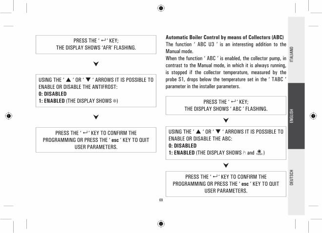
69
PRESS THE ‘ ‘ KEY;THE DISPLAY SHOWS ‘ ABC ’ FLASHING.
PRESS THE ‘ ‘ KEY TO CONFIRM THE PROGRAMMING OR PRESS THE ‘ esc ’ KEY TO QUIT
USER PARAMETERS.
USING THE ‘ ‘ OR ‘ ‘ ARROWS IT IS POSSIBLE TO ENABLE OR DISABLE THE ABC: 0: DISABLED 1: ENABLED (THE DISPLAY SHOWS and )
DEUT
SCH
ENGL
ISH
ITAL
IANO
Automatic Boiler Control by means of Collectors (ABC)The function ‘ ABC U3 ’ is an interesting addition to the Manual mode. When the function ‘ ABC ’ is enabled, the collector pump, in contrast to the Manual mode, in which it is always running, is stopped if the collector temperature, measured by the probe S1, drops below the temperature set in the ‘ TABC ’ parameter in the installer parameters.
USING THE ‘ ‘ OR ‘ ‘ ARROWS IT IS POSSIBLE TO ENABLE OR DISABLE THE ANTIFROST: 0: DISABLED 1: ENABLED (THE DISPLAY SHOWS )
PRESS THE ‘ ‘ KEY TO CONFIRM THE PROGRAMMING OR PRESS THE ‘ esc ’ KEY TO QUIT
USER PARAMETERS.
PRESS THE ‘ ‘ KEY;THE DISPLAY SHOWS ‘AFR’ FLASHING.

70
TROUBLESHOOTING
ANOMALY POSSIBLE CAUSE
During normal operation the control unit displays the symbol and emits an acoustic signal characterized by a series of ‘beeps’.The probe originating the problem is flashing on the display.
The control unit has revealed an anomaly on the probe.The display shows the number of the damaged probe and the type of anomaly present.
The display shows the icon and the control unit emits an acoustic signal characterized by a series of ‘beeps’.
One or more probes are measuring a temperature higher than the relevant programmed safety temperature.
In the selection of the installation to be realized (installer parameter P1) one or more probes flashing.
The probe is miswired or damaged.
Short circuit on probe input (R≈0).COL ShrTS_2 ShrTS_3 ShrTS_4 ShrT
Open circuit on probe input (R=∞).COL OPEnS_2 OPEnS_3 OPEnS_4 OPEn
DEUT
SCH
ENGL
ISH
ITAL
IANO

71
Versorgung 230V~ ±10% 50Hz Rückbeleuchtete alphanumerische LCD-Anzeige Führung von 5 RelaisausgängenKonfiguration der Relaisausgangslogik möglich, bzw. normal oder reverse4 Eingänge für Pt 1000 FühlerTemperaturablesungsbereich -40°C .. +260°CKorrektur von Fühler-Offset getrennt ±5°CVeränderliche Geschwindigkeit der an OUT1 und OUT 2 Ausgänge angeschlossenen Kollektorpumpen, die über Parameter P08 eingestellt wird; nur in der Version mit 2 On/Off SPST Ausgängen + 2 Halbleiterrelaisausgängen (Veränderliche Geschwindigkeit der Kollektorpumpe)Konfiguration von 20 verschiedenen Solaranlagen; nur in der Version mit 4 On/Off SPST AusgängenKonfiguration von 19 verschiedenen Solaranlagen; nur in der Version mit 2 On/Off SPST Ausgängen + 2 Halbleiterrelaisausgängen (Veränderliche Geschwindigkeit der Kollektorpumpe)Graphische Anzeige der konfigurierten AnlagenDiagnostik auf Bildschirm (Zustand Ein-/Ausgänge und Fehlermeldungen)Temperaturanzeige von Kollektor, Kessel und VerbraucherAnzeige der Momentangeschwindigkeit der Kollektorpumpen, nur in der Version mit 2 On/Off SPST Ausgängen + 2 Halbleiterrelaisausgängen (Veränderliche Geschwindigkeit der Kollektorpumpe)Hör-/Sichtmeldungen im Falle einer Störung bzw. eines AlarmsHilfsrelaisaktivierung im Falle eines AlarmsSelbstdiagnostik der ausgeführten Anlage (Funktion Anlageprüfung)Konfiguration der Parameter Installateur durch ein Passwort geschütztAktivierung der Antigefrierfunktion möglichVerbuchung von IntegrierstundenBetriebsart AUTOMATIK / MANUELL / ABC (Automatic Boiler Control)
••••••••
••
••••
•••••••
HAUPTEIGENSCHAFTEN
DEUT
SCH
ENGL
ISH
ITAL
IANO

72
TECHNISCHE SPEZIFIKATIONENVersorgung: 230V~ ±10% 50HzStromverbrauch: 4 VASensoren: 4 x Pt1000 Klasse B DINSensorbetriebbereich: -50°C .. 270°CTemperaturablesungsbereich: -40.0°C .. 260.0°CGenauigkeit: ± 1 °CAuflösung: 0.1 °COffset: auf S1: ±5.0°C auf S2: ±5.0°C auf S3: ±5.0°C auf S4: ±5.0°CPasswort Installateur: 0000 .. 9999 (Default 0000) Hörmeldungen: On/Off (Default On)Ausschaltung Rückleuchte: 20 Sek. nach letztem Drücken Logik OUT2 Relais: NOR=N.O. REV=N.C. Logik der Schaltpläne mit 2 Kollektoren nicht zu verändern (Default N.O.) Logik OUT3 Relais: NOR=N.O. REV=N.C. (Default N.O.)Logik OUT4 Relais: NOR=N.O. REV=N.C. (Default N.O.)
Schaltleistung Kontakte:Für Version mit 4 On/Off SPST Ausgängen: 4x2(1)A max @ 230V~(SPST) Kontakte unter SpannungFür Version mit 2 On/Off SPST Ausgängen + 2Halbleiterrelaisausgängen: 2x2(1)A max @ 230V~(SPST) 2x2(1)A @ 230V~(45 .. 65 Hz) Kontakte unter SpannungSchutzart: IP 40Betriebstemperatur: 0°C .. 40°CLagerungstemperatur: -10°C .. +50°CFeuchtigkeitsgrenze: 20% .. 80% RH nicht kondensierendGehäuse: Material: ABS V0 selbstlöschend Farbe: Signalweiß (RAL 9003)Abmessungen: 156 x 108 x 47 (L x H x T)Gewicht: ~723 gr. (version mit Fühler) ~553 gr. (version ohne Fühler)Befestigung: An der Wand, oder an dem Langloch 144 x 96 mm mittels Metallpratze (wahlfrei)EMC Normen: CEI-EN-55014-2 (1997) CEI-EN-55014-1 (2000)LVD Normen: CEI-EN-60730-1 (1996) CEI-EN-60730-2-9 (1997)
DEUT
SCH
ENGL
ISH
ITAL
IANO

73
ALLGEMEINESDieses Gerät ist ein digital Regler zur steuerung von Thermosolaranlagen. Mit 5 Ausgängen (Ladungsrelais + Alarmrelais) und 4 Eingängen (Fühler) versehen, konfiguriert und führt es bis zu 20 verschiedenen Typen von Thermosolaranlagenschema. Nach Wahl der gewünschten Anlage führt das Steuergehäuse automatisch die Aus- und Eingänge, welche benutzt werden, um Ventile, Pumpen, integrierende Quellen und Fühler zu regulieren, die in der gewählten Anlage tätig sind.Auf der rückbeleuchteten LCD-Anzeige wird der Hydraulikplan der konfigurierten Anlage visualisiert, sowie der Zustand der Ausgänge, der Fühler sowie viele anderen Informationen und Daten.
INBETRIEBNAHMEEIN-/ABSCHALTUNGUm das Steuergehäuse ein- bzw. abzuschalten, halten Sie die Taste “esc“ mindestens 3 Sekunden lang gedrückt. Bei der Einschaltung führt das Steuergehäuse eine Diagnostik des Innenkreises aus, um dessen Betrieb zu überprüfen. Die rote LED blinkt 3 x. Nimmt das Steuergehäuse keine Störung auf, so bleibt die rote LED eingeschaltet. Andernfalls blinkt die LED schnell weiter und auf dem Display wird der Typ von Fehler angezeigt.
RÜCKBELEUCHTUNGRückbeleuchtung des Displays wird nach Betätigung
irgendeiner Taste aktiviert. Nach zirka 20 Sekunden schaltet die Rückbeleuchtung automatisch ab.
HÖRSIGNALEDas Steuergehäuse verfügt über einen Innensummer: bei Betätigung einer Taste bzw. im Falle eines Alarms oder einer Störung wird ein Hörsignal erzeugt.Hörsignale können durch Einstellung von entsprechenden “Parameter Installateur“ ausgeschlossen werden.
FUNKTION PRÜFUNG DER ANGESCHLOSSENEN LADUNGENMittels dieser Funktion, die über dem Parameter Installateur P7 betätigt wird, aktiviert das Steuergehäuse die angeschlossenen Ladungen, damit der Installateur die ausgeführten Anschlüsse überprüfen kann.
ANZEIGE DER TEMPERATURENGewöhnlich zeigt das Steuergehäuse auf dem alphanumerischen Display die durch die angeschlossenen Fühler aufgenommene Temperatur an. Mit den Tasten ‘ ‘ order ‘ ‘ können Sie den Fühler zyklisch wählen, dessen Temperatur Sie visualisieren möchten:
COL S_2 S_3 S_4
DEUT
SCH
ENGL
ISH
ITAL
IANO

74
ANZEIGE DER KOLLEKTORPUMPENGESCHWINDIGKEITNur in der Version mit veränderlicher Geschwindigkeit der KollektorpumpeWenn die Tasten ‘ ‘ order ‘ ‘ im Standardbetrieb gedrückt werden, visualisiert das Steuergehäuse nicht nur die durch die angeschlossenen Fühler aufgenommenen Temperaturen, sondern auch die prozentuale Geschwindigkeit der Kollektorpumpen. Im Falle von Parameter %FS2, wenn der OUT2 Ausgang nicht angeschlossen worden ist, visualisiert das Steuergehäuse für diesen auf 0 eingestellten Parameter. Wenn der gewählte Schaltplan die Installation einer Kollektorpumpen auf OUT2 Ausgang nicht vorsieht, kann der Parameter die numerischen Werte von 0 (N.O. Ausgang) oder 100 (N.C. Ausgang) haben, d.h. der Ausgang ist des ON/OFF Typs.
AUTOMATISCHER / MANUELLER / ABC (Automatic Boiler Control) BETRIEBDas Steuergehäuse kann die gewählte Anlage in 3 verschiedenen Betriebsarten führen:- AUTOMATIK: Bei dieser Betriebsart führt und steuert
das Steuergehäuse den Betrieb der Anlage automatisch, je nach deneingestellten Werten.
- MANUELL: die Kollektorpumpe ist immer aktiv; die einzigen tätigen Kontrollen entsprechen den Höchst- bzw. Sicherheitstemperaturen.
- ABC: die Funktion ist wie im manuellen Betrieb, die Kollektorpumpe wird aber aktiviert, erst wenn die Temperatur auf Kollektor über der auf dem entsprechenden Parameter Installateur eingestellten ‘ T ABC ‘ Temperatur liegt
RESETUm das Gerät rückzustellen, drücken Sie die Taste ‘RESET‘ hinter dem kleinen entfernbaren Deckel; KEINE NADELN BENUTZEN.
PARAMETER INSTALLATEURDrücken Sie die Taste ‘ ‘ um auf die Parameter Installateur zuzugreifen.
PassworteinführungAuf dem Display erscheint ‘ PWD 0000 ’, deren erste Ziffer links blinkt, um zu zeigen, dass das Passwort gefordert wird. Mit den Tasten ‘ ‘ order ‘ ‘ führen Sie die 4 Ziffern des Passworts ein.Mit der Taste ‘ ‘ wird die eingeführte Ziffer bestätigt, und man kann die zweite Ziffer wählen, usw. bis zur letzten Ziffer.Mit der Taste ‘ ‘ wird die letzte Ziffer bestätigt, und man kann auf die Parameter Installateur zuzugreifen.Das Steuergehäuse wird mit Passwort ‘0000’ geliefert.
DEUT
SCH
ENGL
ISH
ITAL
IANO

75
Änderung des Passworts Um das gespeicherte Passwort zu ändern, drücken sie die Taste ‘ ‘, und gehen sie folgendermaßen vor:Mit der Taste ‘ esc ’ können Sie in irgendeinem Moment die Passwortführung verlassen.
DRÜCKEN SIE DIE TASTE ‘MENU’.
AUF DEM DISPLAY WIRD ‘ PWDH0000 ‘ ANGEZEIGT.
FÜHREN SIE DAS LAUFENDE PASSWORT EIN.
(gleicher Vorgang wie oben beschrieben)
AUF DEM DISPLAY WIRD ‘ PWDN0000 ‘ANGEZEIGT.
FÜHREN SIE DAS NEUE PASSWORT EIN.
AUF DEM DISPLAY WIRD ‘ PWDC0000 ‘ ANGEZEIGT.
FÜHREN SIE DAS NEUE PASSWORT EIN.
DAS STEUERGEHÄUSE SPEICHERT DAS NEUE PASSWORT
UND GREIFT AUF PARAMETER INSTALLATEUR ZU.
Gebrauch von Parametern InstallateurNach Einführung des korrekten Passworts greift man auf die Betriebsart Änderung der Parameter Installateur zu: das Ikon‘ SET ’ ist eingeschaltet. Die erste erteilte Information betrifft das Modell des gerade benutzten Steuergehäuses und der abänderliche Parameter, ‘ P1 ’.Mit den Tasten ‘ ‘ order ‘ ‘ kann man die verschiedenen Parameter durchblättern. Mit der Taste ‘ ‘ greift man auf die Betriebsart Änderung des gewählten Parameters zu.Diese Betriebsart wird mit der Taste ‘ esc ’ verlassen.
ÜBER DEM ANFANGSBILDSCHIRM DRÜCKEN SIE DIE TASTE ‘ ‘.
DEUT
SCH
ENGL
ISH
ITAL
IANO
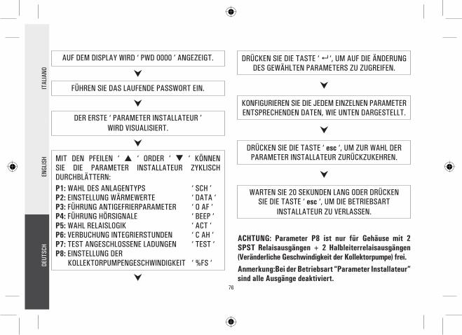
76
AUF DEM DISPLAY WIRD ‘ PWD 0000 ’ ANGEZEIGT.
FÜHREN SIE DAS LAUFENDE PASSWORT EIN.
DER ERSTE ‘ PARAMETER INSTALLATEUR ’WIRD VISUALISIERT.
MIT DEN PFEILEN ‘ ‘ ORDER ‘ ‘ KÖNNEN SIE DIE PARAMETER INSTALLATEUR ZYKLISCH DURCHBLÄTTERN:P1: WAHL DES ANLAGENTYPS ‘ SCH ’P2: EINSTELLUNG WÄRMEWERTE ‘ DATA ‘P3: FÜHRUNG ANTIGEFRIERPARAMETER ‘ O AF ‘P4: FÜHRUNG HÖRSIGNALE ‘ BEEP ‘P5: WAHL RELAISLOGIK ‘ ACT ‘P6: VERBUCHUNG INTEGRIERSTUNDEN ‘ C AH ‘P7: TEST ANGESCHLOSSENE LADUNGEN ‘ TEST ‘P8: EINSTELLUNG DER KOLLEKTORPUMPENGESCHWINDIGKEIT ‘ %FS ‘
DRÜCKEN SIE DIE TASTE ‘ ‘, UM AUF DIE ÄNDERUNG DES GEWÄHLTEN PARAMETERS ZU ZUGREIFEN.
KONFIGURIEREN SIE DIE JEDEM EINZELNEN PARAMETER ENTSPRECHENDEN DATEN, WIE UNTEN DARGESTELLT.
WARTEN SIE 20 SEKUNDEN LANG ODER DRÜCKEN SIE DIE TASTE ‘ esc ‘, UM DIE BETRIEBSART
INSTALLATEUR ZU VERLASSEN.
DRÜCKEN SIE DIE TASTE ‘ esc ‘, UM ZUR WAHL DER PARAMETER INSTALLATEUR ZURÜCKZUKEHREN.
ACHTUNG: Parameter P8 ist nur für Gehäuse mit 2 SPST Relaisausgängen + 2 Halbleiterrelaisausgängen (Veränderliche Geschwindigkeit der Kollektorpumpe) frei.Anmerkung:Bei der Betriebsart “Parameter Installateur” sind alle Ausgänge deaktiviert.
DEUT
SCH
ENGL
ISH
ITAL
IANO

77
MIT DEN PFEILEN ‘ ‘ oder ‘ ‘ KÖNNEN SIE DIE WÄRMEWERTE ZYKLISCH DURCHBLÄTTERN:- Sicherheitstemperaturen- Differenzierungen- Hysterese der Differenzierungen- Hysterese der Sicherheitsthermostaten- Hysterese der Thermostaten- Offset - Höchsttemperaturen- Integrierungstemperatur - ABC, d.h. automatische Steuerung des Kessels, Temperatur
NACH WAHL DES PARAMTERS P2 DRÜCKEN SIE DIE TASTE ‘ ‘.
P1: WAHL DES ANLAGENTYPSMit den Tasten ‘ ‘ order ‘ ‘ werden alle ausführbaren Anlagen angezeigt. Falls ein Fühler der gewählten Anlage eine Störung aufweißt, bzw. nicht angeschlossen ist, blinkt der selbe Fühler auf dem Display.Um die gewünschte Anlage zu bestätigen, drücken Sie die Taste ‘ ‘; das Steuergehäuse speichert die Wahl und zeigt die Liste der Parameter wieder an.Mit der Taste ‘ esc ’ wird die Wahl gelöscht. Das Steuergehäuse verlässt die durchgeführte Änderung und zeigt die Liste der Parameter noch mal.
Auf Anhang “SCHEMA” sind die Parameter verzeichnet, welche die Einstellung des ausgewählten Schemas beeinflussen. Diese können durch den zweiten Parameter-Installateur modifiziert werden.
P2: EINSTELLUNG DER WÄRMEWERTEMit diesem Parameter werden die Wärmewerte der gewählten Anlage eingestellt.
Das Steuergehäuse wird mit voreingestellten Wärmewerten für einen optimalen Betrieb geliefert. Die Änderung solcher Werte soll durch qualifiziertes Fachpersonal ausgeführt werden.
DRÜCKEN SIE DIE TASTE ‘ ‘, UM AUF DIE ÄNDERUNG DES GEWÄHLTEN WÄRMEWERTES ZU ZUGREIFEN; DER
WERT FÄNGT AN, ZU BLINKEN.
DEUT
SCH
ENGL
ISH
ITAL
IANO

78
MIT DEN PFEILEN ‘ ‘ oder ‘ ‘ KÖNNEN SIE DIE ANTIGEFRIERWERTE ZYKLISCH DURCHBLÄTTERN:- Antigefriertemperaturen ‘ TAF ’- Einschaltintervall für Kollektorpumpe ‘ P ON ‘- Ausschaltintervall für Kollektorpumpe ‘ P OFF ‘- Dauer der Antigefrierprüfung ‘ TMR ‘
NACH WAHL DES PARAMETERS P3 DRÜCKEN SIE DIE TASTE ‘ ‘.
DRÜCKEN SIE DIE TASTE ‘ ‘, UM AUF DIE ÄNDERUNG DES GEWÄHLTEN WÄRMEWERTES ZU ZUGREIFEN; DER
WERT FÄNGT AN, ZU BLINKEN.
MIT DEN PFEILEN ‘ ‘ oder ‘ ‘ STELLEN SIE DEN GEWÜNSCHTEN NUMERISCHEN WERT EIN.
DRÜCKEN SIE DIE TASTE ‘ ‘, UM DIE AUSGEFÜHRTE EINSTELLUNG ZU BESTÄTIGEN ODER DRÜCKEN SIE DIE
TASTE ‘ esc ’, UM DIE ÄNDERUNG ZU LÖSCHEN.
MIT DEN PFEILEN ‘ ‘ oder ‘ ‘ STELLEN SIE DEN GEWÜNSCHTEN NUMERISCHEN WERT EIN.
Auf Anhang “PARAMETER” sind die Einstellbereiche verzeichnet, die jede einzige Angabe betreffen.
P3: FÜHRUNG ANTIGEFRIERPARAMETERMit diesem Parameter werden die Werte der Antigefrierfunktion eingestellt.Das Steuergehäuse wird mit voreingestellten Antigefrierwerten für einen optimalen Betrieb geliefert. Die Änderung solcher Werte soll durch qualifiziertes Fachpersonal ausgeführt werden.
DRÜCKEN SIE DIE TASTE ‘ ‘, UM DIE AUSGEFÜHRTE EINSTELLUNG ZU BESTÄTIGEN ODER DRÜCKEN SIE DIE
TASTE ‘ esc ’, UM DIE ÄNDERUNG ZU LÖSCHEN.
DEUT
SCH
ENGL
ISH
ITAL
IANO
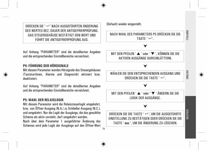
79
DRÜCKEN SIE ‘ ‘ NACH AUSGEFÜHRTEN ÄNDERUNG DES WERTES BEZ. DAUER DER ANTIGEFRIERPRÜFUNG.
DAS STEUERGEHÄUSE BESTÄTIGT DEN WERT UND FÜHRT DIE ANTIGEFRIERPRÜFUNG AUS.
NACH WAHL DES PARAMETERS P5 DRÜCKEN SIE DIE TASTE ‘ ‘.
MIT DEN PFEILEN ‘ ‘ oder ‘ ‘, KÖNNEN SIE DIE AKTIVEN AUSGÄNGE DURCHBLÄTTERN.
WÄHLEN SIE DEN ENTSPRECHENDEN AUSGANG UND DRÜCKEN SIE DIE TASTE ‘ ‘.
MIT DEN PFEILEN ‘ ‘ oder ‘ ‘ ÄNDERN SIE DIE LOGIK DER AUSGÄNGE.
Auf Anhang “PARAMETER” sind die detaillierten Angaben und die entsprechenden Einstellbereiche verzeichnet.
P4: FÜHRUNG DER HÖRSIGNALEMit diesem Parameter werden Hörsignale des Steuergehäuses (Tastaturtönen, Alarme und Diagnostik) aktiviert bzw. deaktiviert.
Auf Anhang “PARAMETER” sind die detaillierten Angaben und die entsprechenden Einstellbereiche verzeichnet.
P5: WAHL DER RELAISLOGIKMit diesem Parameter wird die Relaissteuerlogik umgekehrt, bzw. von Öffner-Ausgang (N.A.) zu Schließer-Ausgang (N.C.), und umgekehrt. Nur die Logik der Ausgänge, die das gewählte Schema als aktiv vorsieht, darf umgekehrt werden.Nach über dem Parameter 1 ausgeführter Änderung des Schemas wird jede Logik der Ausgänge auf den Öffner-Wert
(Default) wieder eingestellt.
DRÜCKEN SIE DIE TASTE ‘ ‘, UM DIE AUSGEFÜHRTE EINSTELLUNG ZU BESTÄTIGEN ODER DRÜCKEN SIE DIE
TASTE ‘ esc ’, UM DIE ÄNDERUNG ZU LÖSCHEN.
DEUT
SCH
ENGL
ISH
ITAL
IANO

80
NACH WAHL DES PARAMETERS P6 DRÜCKEN SIE DIE TASTE ‘ ‘.
IM DISPLAY WIRD ‘ H ’ VISUALISIERT, BZW. DIE STUNDEN VON REELLER AKTIVIERUNG DER INTEGRIERQUELLE.
DRÜCKEN SIE DIE TASTE ‘ ‘.AUF DEM DISPLAY BLINKT ‘ H ’.
BEI BETÄTIGUNG DER TASTE ‘ ‘ WIRD DER ZÄHLER AUF NULL GESTELLT. BEI BETÄTIGUNG DER TASTE ‘ esc ’
WERDEN DIE LAUFENDEN STUNDEN VISUALISIERT.
NACH WAHL DES PARAMETERS P7 DRÜCKEN SIE DIE TASTE ‘ ‘.
Die Ausgänge, deren Logik modifizierbar ist, sind höchstens 3. Sie sind auf Paragraph “Parameter“ verzeichnet.
P6: VERBUCHUNG INTEGRIERSTUNDENMit diesem Parameter werden die Stunden von reeller Aktivierung der Integrierquelle visualisiert bzw. auf Null gestellt.
Die Zählung der Aktivierungsstunden der Integrierung liegt zwischen 0000 .. 9999. Wenn der Höchstwert erreicht wird, schaltet die Zählung ab.
P7: PRÜFUNG ANGESCHLOSSENE LADUNGENMit diesem Parameter wird die Betriebsprüfung der an das Steuergehäuse angeschlossenen Ladungen ausgeführt. Das Steuergehäuse kontrolliert die angeschlossenen Ladungen je nach dem konfigurierten Schema, indem es alle freien Ausgänge in Reihefolge von je 10 Sekunden aktiviert. Der Prüfung Reihefolge, nach Vielfachen von 5, wird über dem einzigen freien Parameter ‘ TMR ‘ eingestellt. Prüfungsaktivierung wird auf dem Display durch Einschaltung des Ikons ‘ TIMER ‘ signalisiert.
AUF DEM DISPLAY WIRD ‘ TMR ’ BZW. DIE ZAHL VON PRÜFUNGSSCHRITTEN VISUALISIERT.
DEUT
SCH
ENGL
ISH
ITAL
IANO

81
DRÜCKEN SIE DIE TASTE ‘ ‘. AUF DEM DISPLAY BLINKT ‘TMR’.
MIT DEN TASTEN ‘ ‘ oder ‘ ‘ WIRD DIE ZAHL BEI SCHRITTEN VON 5, 10, 15, 20, 25 GEÄNDERT.
DRÜCKEN SIE DIE TASTE ‘ ‘, UM DEN EINGESTELLTEN WERT ZU BESTÄTIGEN UND DIE LADUNGSPRÜFUNG ZU STARTEN. MIT DER TASTE ‘ esc ’ WIRD DIE ÄNDERUNG GELÖSCHT UND KEHRT MAN ZUR ANZEIGE DER ZAHL
VON VOREINGESTELLTEN SCHRITTEN ZURÜCK.
P8: EINSTELLUNG DER KOLLEKTORPUMPENGESCHWINDIGKEITNur in der Version mit veränderlicher Geschwindigkeit der KollektorpumpeÜber diesem Parameter, der mit der ‘Menu’ Taste gewählt wird, werden die Daten zur Führung der Kollektorpumpengeschwindigkeit eingestellt, die an die OUT1 / OUT2 Ausgänge angeschlossen sind.
Das Funktionsprinzip, das die Geschwindigkeitsänderung der Kollektorpumpen steuert, entspricht dem Anspruch, den Temperaturunterschied zwischen Solarkollektor und Kessel (T) so konstant wie möglich einzuhalten.Da es bekannt ist, dass das T bei erhöhender einfallenden Solarstrahlung die Neigung hat, größer zu werden, wird es empfohlen, um das T bei gleicher einfallenden Solarstrahlung zu verkleinern, die Durchlaufzeit der Flüssigkeit im Kollektor zu reduzieren, bzw. die Geschwindigkeit der durchgehenden Flüssigkeit zu erhöhen und damit die Kollektorpumpendrehzahl zu erhöhen.Über Parameter P8 wi rd die prozentuale Betriebsmindestgeschwindigkeit der Kollektorpumpen eingestellt, sowie die notwendige Temperaturänderung gegenüber dem T, um die Geschwindigkeit der Kollektorpumpen um 10% (INC Parameter) zu erhöhen.
DEUT
SCH
ENGL
ISH
ITAL
IANO

82
MIT PFEILEN ‘ ‘ UND ‘ ‘ WERDEN KOLLEKTORPUMPENPARAMETER GEWÄHLT:MINDESTGESCHWINDIGKEIT OUT 1 (%) ‘ %MN1 30 ‘MINDESTGESCHWINDIGKEIT OUT 2 (%) ‘ %MN1 30 ‘10% ZUNAHME ‘ INC 2.0°C ‘
TASTE ‘ ‘ DRÜCKEN, UM AUF DIE ÄNDERUNG DESGEWÄHLTEN PARAMETERS ZU ZUGREIFEN;
DER PARAMETER BEGINNT ZU BLINKEN.
IMIT PFEILEN ‘ ‘ UND ‘ ‘ DEN GEWÜNSCHTENNUMERISCHEN WERT EINSTELLEN.
TASTE ‘ ‘ DRÜCKEN, UM DIE AUSGEFÜHRTE EINSTELLUNG ZU BESTÄTIGEN BZW. TASTE ‘esc’
DRÜCKEN, UM DIE ÄNDERUNG ZU LÖSCHEN.
DEM VERBRAUCHER ZUGÄNGLICHE FUNKTIONENDie dem Verbraucher zugänglichen Funktionen sind begrenzt und erlauben die Konfigurierung von Werten nicht, welche die Führung der Anlage beeinflussen.Dem Verbraucher einzige erlaubten Operationen sind:
Ein- / Ausschaltung des Steuergehäuses
Manuelle Führung der AnlageMit der Taste ‘ ‘ wird der manuelle Betrieb des Steuergehäuses aktiviert bzw. deaktiviert.Bei eingeschaltetem manuellen Betrieb leuchtet das Ikon ‘ ‘ auf dem Display. Während des manuellen Betriebs läuft die Kollektorpumpe immer, unabhängig von den angemessenen
PARAMETER P8 ÄHLEN UND TASTE ‘ ‘ DRÜCKEN.
Das Steuergehäuse wird mit voreingestellten Daten geliefert, was den optimalen Betrieb ermöglicht.Nur qualifiziertes Fachpersonal darf solche Werte ändern.
DEUT
SCH
ENGL
ISH
ITAL
IANO
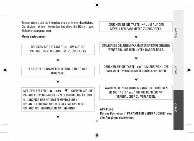
83
MIT DEN PFEILEN ‘ ‘ oder ‘ ‘ KÖNNEN SIE DIE PARAMETER VERBRAUCHER ZYKLISCH DURCHBLÄTTERN: U1: ANZEIGE DER HÖCHSTTEMPERATUREN U2: ANTIGEFRIERAKTIVIERUNG/ENTAKTIVIERUNG U3: ABC AKTIVIERUNG/ENTAKTIVIERUNG
DER ERSTE ‘ PARAMETER VERBRAUCHER ’ WIRD ANGEZEIGT.
DRÜCKEN SIE DIE TASTE ‘ ‘, UM AUF DEN GEWÄHLTEN PARAMETER ZU ZUGREIFEN.
DRÜCKEN SIE DIE TASTE ‘ esc ‘, UM ZUR WAHL DER PARAMETER VERBRAUCHER ZURÜCKZUKEHREN.
WARTEN SIE 20 SEKUNDEN LANG ODER DRÜCKEN SIE DIE TASTE ‘ esc ‘, UM DIE BETRIEBSART
VERBRAUCHER ZU VERLASSEN.
STELLEN SIE DIE JEDEM PARAMETER ENTSPRECHENDEN WERTE EIN, WIE HIER UNTEN DARGESTELLT.
ACHTUNG!Bei der Betriebsart ‘ PARAMETER VERBRAUCHER ‘ sind alle Ausgänge deaktiviert.
DRÜCKEN SIE DIE TASTE ‘ ‘, UM AUF DIE‘ PARAMETER VERBRAUCHER ’ ZU ZUGREIFEN.
Temperaturen, und die Integrierpumpe ist immer deaktiviert. Die einzigen aktiven Kontrollen betreffen die Höchst- bzw. Sicherheitstemperaturen.
Menu Verbraucher
DEUT
SCH
ENGL
ISH
ITAL
IANO

84
DEUT
SCH
ENGL
ISH
ITAL
IANO
AntigefrieraktivierungMit der Antigefrierparameter ‘ AFR U2 ‘ wird die Antigefrierfunktion aktiviert bzw. deaktiviert. Die Führung der Antigefrierwerte erfolgt über den Parametern Verbraucher.
DRÜCKEN SIE DIE TASTE ‘ ‘. AUF DEM DISPLAY WIRD DIE ZAHL DES BLINKENDEN FÜHLERS
ANGEZEIGT. MIT DER TASTE ‘ esc ‘ KEHR MAN ZUR ANZEIGE DER PARAMETER VERBRAUCHER ZURÜCK.
MIT DER TASTE ‘ ‘ WIRD DIE BISHER AUFGENOMMENE TEMPERATUR AUF NULL GESTELLT. MIT DER TASTE ‘ esc ’ KEHR MAN ZUR ANZEIGE DER
GESPEICHERTEN TEMPERATUR ZURÜCK.
DRÜCKEN SIE DIE TASTE ‘ esc ‘, UM DIE ANZEIGE DER HÖCHSTTEMPERATUR ZU VERLASSEN.
DRÜCKEN SIE DIE TASTE ‘ ‘. AUF DEM DISPLAY BLINKT ‘AFR ‘.
MIT DEN PFEILEN ‘ ‘ oder ‘ ‘ KÖNNEN SIE DIE AUFGENOMMENEN TEMPERATUREN ZYKLISCH DURCHBLÄTTERN:
TM1 TM2 TM3 TM4
DRÜCKEN SIE DIE TASTE ‘ ‘, UM AUF DIE ANZEIGE DER TEMPERATUREN ZU ZUGREIFEN.
Anzeige der aufgenommenen HöchsttemperaturenMit dem Parameter ‘ TMAX U1 ‘ wird die durch jeden TM- Fühler aufgenommene Höchsttemperatur angezeigt.
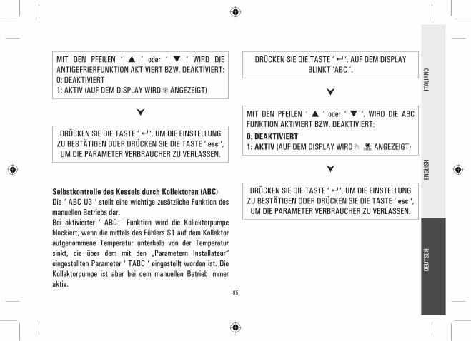
85
DEUT
SCH
ENGL
ISH
ITAL
IANO
DRÜCKEN SIE DIE TASTE ‘ ‘. AUF DEM DISPLAY BLINKT ‘ABC ‘.
DRÜCKEN SIE DIE TASTE ‘ ‘, UM DIE EINSTELLUNG ZU BESTÄTIGEN ODER DRÜCKEN SIE DIE TASTE ‘ esc ‘, UM DIE PARAMETER VERBRAUCHER ZU VERLASSEN.
MIT DEN PFEILEN ‘ ‘ oder ‘ ‘. WIRD DIE ABC FUNKTION AKTIVIERT BZW. DEAKTIVIERT: 0: DEAKTIVIERT 1: AKTIV (AUF DEM DISPLAY WIRD ANGEZEIGT)
Selbstkontrolle des Kessels durch Kollektoren (ABC)Die ‘ ABC U3 ‘ stellt eine wichtige zusätzliche Funktion des manuellen Betriebs dar. Bei aktivierter ‘ ABC ‘ Funktion wird die Kollektorpumpe blockiert, wenn die mittels des Fühlers S1 auf dem Kollektor aufgenommene Temperatur unterhalb von der Temperatur sinkt, die über dem mit den „Parametern Installateur“ eingestellten Parameter ‘ TABC ‘ eingestellt worden ist. Die Kollektorpumpe ist aber bei dem manuellen Betrieb immer aktiv.
DRÜCKEN SIE DIE TASTE ‘ ‘, UM DIE EINSTELLUNG ZU BESTÄTIGEN ODER DRÜCKEN SIE DIE TASTE ‘ esc ‘, UM DIE PARAMETER VERBRAUCHER ZU VERLASSEN.
MIT DEN PFEILEN ‘ ‘ oder ‘ ‘ WIRD DIE ANTIGEFRIERFUNKTION AKTIVIERT BZW. DEAKTIVIERT:0: DEAKTIVIERT 1: AKTIV (AUF DEM DISPLAY WIRD ANGEZEIGT)
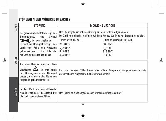
86
STÖRUNGEN UND MÖGLICHE URSACHEN
STÖRUNG MÖGLICHE URSACHE
Bei gewöhnlichem Betrieb zeigt das Steuergehäuse das Symbol auf dem Display an.Es wird ein Hörsignal erzeugt, das durch eine Reihe von Pieptönen gekennzeichnet ist. Der Fühler, der die Störung erzeugt hat, blinkt.
Das Steuergehäuse hat eine Störung auf den Fühlern aufgenommen.Die Zahl vom fehlerhaften Fühler wird mit Angabe des Typs von Störung visualisiert.
Auf dem Display wird das Ikon
visualisiert Es wird durch das Steuergehäuse ein Hörsignal erzeugt, das durch eine Reihe von Pieptönen gekennzeichnet ist.
Ein oder mehrere Fühler haben eine höhere Temperatur aufgenommen, als die entsprechende eingestellte Sicherheitstemperatur.
In der Wahl von auszuführender Anlage (Parameter Installateur P1) blinkt ein oder mehrere Fühler.
Der Fühler ist nicht angeschlossen worden oder ist fehlerhaft.
Fühler im Kurzschluss (R≈0).COL ShrTS_2 ShrTS_3 ShrTS_4 ShrT
Fühler offen (R=∞).COL OPEnS_2 OPEnS_3 OPEnS_4 OPEn
DEUT
SCH
ENGL
ISH
ITAL
IANO

87
ATTENZIONEL’installatore è tenuto al rispetto di tutte le norme tecniche applicabili al fine di garantire la sicurezza dell’impianto.
WARNINGThe installation technician shall operate in full compliance with all the applicable technical standards in order to grant the unit safety.
ACHTUNGDer Installateur ist verpflichtet, allen technischen gültigen Normen zu folgen, um die Sicherheit der Anlage zu garantieren.
GARANZIANell’ottica di un continuo sviluppo dei propri prodotti, il costruttore si riserva il diritto di apportare modifiche a dati tecnici e prestazioni senza preavviso. Il consumatore è garantito contro i difetti di conformità del prodotto secondo la Direttiva Europea 1999/44/ nonché il documento sulla politica di garanzia del costruttore. Su richiesta è disponibile presso il venditore il testo completo della garanzia.
WARRANTYIn the view of a constant development of their products, the manufacturer reserves the right for changing technical data and features without prior notice. The consumer is guaranteed against any lack of conformity according to the European Directive 1999/44/EC as well as to the manufacturer’s document about the warranty policy. The full text of warranty is available on request from the seller.
GARANTIEZur kontinuerlichen Weiterentwicklung der eigenen Produkte, behält sich der Hersteller das Recht vor, ohne vorherige Ankündigung, technische Änderungen an Produkten und Dienstleistungen vorzunehmen. Der Hersteller haftet für die Produktkonformität gemäß der Europäischen Richtlinie 1999/44/EG und dem Dokument zur Produktgarantiepolitik der Hersteller. Auf Anfrage steht Ihnen beim Händler der ausführliche Produktgarantietext zur Verfügung.

@IST01100AAN 015340A0 120608