central pollution control board - cpcb enviscpcbenvis.nic.in/cpcb_newsletter/clean coal...
TRANSCRIPT

Central Pollution Control Board
http://www.cpcbenvis.nic.in/newsletter/cleancoal-june2000/jun2000.htm[9/6/2012 10:59:19 AM]
Coal ReservesCoal Production and DemandCoal Mining PracticesCoal QualityEnvironmental Issues of Coal MiningEnvironmental Issues in Coal Based Power GenerationCoal Cleaning MethodsClean Coal Combustion TechnologiesCoal Bed Methane RecoveryPost Combustion TechnologyIssues and Action Points at a Glance

Central Pollution Control Board
http://www.cpcbenvis.nic.in/newsletter/cleancoal-june2000/jun00edi.htm[9/6/2012 10:59:20 AM]
Contents
Archives
Home
Among the fossil fuels, coal has acquired the dubious distinction of being the dirtiest one.Such an attribute is on account of environmental damage and pollution problems causedduring mining, processing, end use and wastes of coal. Land subsidence in undergroundmines, ugly scars of land in abandoned open cast mines, emissions of fly ash duringcombustion of coal and huge quantities of ash generated from boilers of coal based powerplants and industrial houses are among the hosts of problems associated with handling anduse of coal. Emission of carbon dioxide, an important component of "green house gases"(GHGs) and global warming, is yet another emerging concern linked with burning of coal. However, inspite of all the odds, coal constitutes a major source for catering to our growingenergy needs. With the proper technologies and initiatives for better management, it ispossible to reduce the hazards otherwise caused. Through scientific mining practicesfollowed by land reclamation, beneficiation for ash reduction at source, improvement incombustion methods, use of efficient electrostatic precipitators/bag filters for trapping of flyash emission and effective management of ash including its utilisation for bricks, cementand such other purposes, many of the problems can be prevented and controlled. With these objectives in view, the Central Pollution Control Board (CPCB) has laid downthe environmental guidelines for coal mining activities, prescribed the use of beneficiatedcoal with lower ash content in power plants and laid down the norms for emissions andeffluents from coal combustion systems. In this Issue of Parivesh, as collated by my colleagues Dr. S. Paliwal, Shri Lalit Kapur andDr. B. Sengupta, an overview of the present status and possibilities for clean coal initiativesare highlighted.
Dilip Biswas Chairman,CPCB

Central Pollution Control Board
http://www.cpcbenvis.nic.in/newsletter/cleancoal-june2000/jun2000coal.htm[9/6/2012 10:59:21 AM]
Clean Coal Initiatives
COAL RESERVES
India with 2.7 percent of the world reserves, ranks sixth in the world in coal resources, occurring in Gondwana andtertiary formations. The Gondwana coals are largely confined to river valleys such as the Damodar (West Bengal andBihar), Mahanadi (Orissa), and Godavari (Maharashtra and Andhra Pradesh). Coal fields of Assam of Jaintia andBarail series belong to the Tertiary age. The lignite deposits of Jammu and Kashmir, Kerala, Tamil Nadu andGujarat are also of the Tertiary age. The geographical distribution of coal reserves is shown in Fig. 1.

Central Pollution Control Board
http://www.cpcbenvis.nic.in/newsletter/cleancoal-june2000/jun2000coal.htm[9/6/2012 10:59:21 AM]
Most of the coal reserves in India are concentrated in the peninsular part within 78 to 88 degrees East longitude and22 to 24 degrees North latitude. As per Geological Survey of India, the estimated coal reserves, down to a depth of1,200 metre, stood at 208751.5 million tonnes as on 1.1.99. Of these estimated reserves, down to a depth of 1,200metres, which is considered economically viable are 90 percent of the total reserves. About 83 percent of totalresources are non-coking coals and 14 percent belongs to coking coals (Table 1).
Table 1 : Gradewise Reserves of Non-Coking Coal (billion tonnes)
S.No.
Name of major Coalfields
Superior Grade
(A+B+C)
(5800 Kcal/Kg)
IntermediateGrade (D)
(5000Kcal/Kg)
Inferior Grade
(E+F+G)
(4000 Kcal/Kg)
1. Raniganj & Mugma 9.76 3.10 4.50
2. Rajmahal 0.46 1.71 8.24
3. Jharia 0.19 0.44 5.47
4. East Bokaro 0.02 0.02 0.02
5. West Bokaro 0.01 0.04 0.12
6. Ramgarh - 0.02 0.02
7. South Karanpura 1.06 1.08 2.43
8. North Karanpura 0.68 1.23 8.31

Central Pollution Control Board
http://www.cpcbenvis.nic.in/newsletter/cleancoal-june2000/jun2000coal.htm[9/6/2012 10:59:21 AM]
9. Singrauli 1.21 1.52 6.48
10. Pathakhera 0.07 0.10 0.19
11. Pench-Kanhan 0.64 0.32 0.45
12. Umrer - - 0.09
13. Kamptee-Silewara 0.43 0.33 0.61
14. Wardha Valley 0.35 1.55 2.31
15. CIC 1.71 0.29 0.29
16. Korba 0.72 0.44 6.86
17. Talcher 0.95 0.65 21.91
18. Ib-Valley 0.56 2.45 17.75
19. North Eastern 0.83 - -
20. Godavari Valley 2.07 2.36 4.63
21. Other Minor Coalfields 2.05 1.95 16.00
TOTAL (billion tonnes) 23.80 19.60 106.76
Percent(%) (16) (13) (710)
Besides being a major source of energy generation, coal is also utilised as feedstock for a variety of products asshown in the schematic diagram on coal utilisation (Fig. 2).
Back to Content

Central Pollution Control Board
http://www.cpcbenvis.nic.in/newsletter/cleancoal-june2000/jun2000coal1.htm[9/6/2012 10:59:22 AM]
Clean Coal Initiatives
COAL PRODUCTION & DEMAND
Coal production in India sharply increased from 30 million tonnes in 1940 to over 290 million tonnes in 1998-99.Now, India ranks 3rd amongst the coal producing countries in the World. Future demand of coal for major industrialuses is given in Table 2.
Table 2 : Coal Demand Forecast (Million tonnes)
Sector Estimated Coal Demand
1996-97* 2001-2002 2006-2007 2009-2010
Power 199 285 400 500
Steel 25.53 49 60 68
Consent 11.34 21 30 37
Others 50.57 61 75 85
Total 286.46 416 565 690
* Actual Coal supplied.
About 70 percent of total production is used by the power generation sector while steel and cement are also amongthe major consumers (Table 3).
Table 3 : Consumption of coal in power sector
Year Coal consumption (million tonnes) Electricity installed capacity(MW)
1995-96 184.52 58675
1996-97 199.00 60,000
1997-98 212.92 63038
1998-99 208 67000
Back to Content

Central Pollution Control Board
http://www.cpcbenvis.nic.in/newsletter/cleancoal-june2000/jun2000coal1.htm[9/6/2012 10:59:22 AM]

Central Pollution Control Board
http://www.cpcbenvis.nic.in/newsletter/cleancoal-june2000/jun2000coal2.htm[9/6/2012 10:59:22 AM]
Clean Coal Initiatives
COAL MINING PRACTICES
India's total land area is 3.29 million sq. km and within this only 0.45% area (about 16,000 sq. km) is coal bearing.Out of this coal bearing area, active coal mining area is about 2500 sq. km. Maximum land degradation in coalmining is caused by open-cast mining and it is currently confined to 20% of the coal bearing land. Additional areasthat could be used for open-cast mining would be around 5 to 10% of the coal bearing land. Thus, the area whereland degradation has taken place and is likely to take place is around 0.2% of the land mass.
Underground production of coal peaked in the late seventies and has fallen slowly since then. Surface mining, on theother hand, has soared from16 to 160 million tonnes per annum. Of the 588 mines in India, 355 are under-ground,but opencast accounts for 75 percent of production and employs only 16 percent of the total mining work force.Productivity is higher in the opencast sector. However, the pace of growth cannot be sustained for long, as strippingratios will increase and mining operations run into land access and other environmental problems. Undergroundmining is largely a 'board and pillar' operation. Longwall was introduced in 1978 and by 1993, 20 longwall unitswere installed.
Back to Content

Central Pollution Control Board
http://www.cpcbenvis.nic.in/newsletter/cleancoal-june2000/jun2000coal3.htm[9/6/2012 10:59:23 AM]
Clean Coal Initiatives
COAL QUALITY
The quality of Indian coal is mainly attributed to its origin. Due to drift origin of Indian coal, inorganic impurities areintimately mixed in the coal matrix, resulting in difficult beneficiation characteristics. Over 200 million tonnes ofcoal reach the consumers with ash content averaging 40 percent. Based on ash content, gross calorific value anduseful heat value, Indian coal is classified in six categories as given in Table 4.
Table 4 : Grading and Quality of coal
Grade (Ash + Moisture % )Approx.
Useful heat value(UHV)
(Kcal./Kg)
A 19.5 or less Above 6200
B 24-19.5 5600-6200
C 28.7-24 4940-5600
D 34-28.7 4200-4940
E 40-34 3360-4200
F 47-40 2400-3360
G 55-47 1300-2400
Sulphur content in Indian coal is generally less than 0.6 percent and the Chlorine content is less than 0.1 percent.Mercury in coal ranges from 0.01 to 1.1 ppm in Indian coals against upto 20 ppm in Russian coals, 0.2 to 2.0 ppm inBelgium coals, 0.03 to 1.3 ppm in Canadian coals and 0.01 to 2.0 ppm in American coals. ( Source : Mishraet.al.(1997) "Clean coal technolgy – Indian context"; Indo-European Seminar on Clean coal technology, New Delhi)
Back to Content

Central Pollution Control Board
http://www.cpcbenvis.nic.in/newsletter/cleancoal-june2000/jun2000coal4.htm[9/6/2012 10:59:25 AM]
Clean Coal Initiatives
CLEAN COAL COMBUSTION TECHNOLOGIES
Steam turbines can run on a variety of fuels but coal continues to remain a popular choice. However, the traditionalcoal-fired plants suffer from two major drawback: overall efficiency levels are low and pollution levels are high.
Growing environmental concerns and the need to improve conversion efficiency levels have led to the developmentof clean coal technologies. The most popular of these technologies are Fluidised Bed Combustion (FBC), PressurisedFluidised Bed Combustion Combined Cycle (PFBC) and Integrated Gasification Combined Cycle (IGCC).
Improvement in overall performance of steam turbines for thermal power plants can be brought about largely throughtwo kinds of advancement. Firstly,through improvement in mechanical efficiency by reducing aerodynamic andleakage losses as the steam expands through the turbine. Secondly, through improvement in thermodynamicefficiency by increasing the temperature and pressure at which heat is added to the power cycle.
Supercritical Technology
The steam temperature can be raised to levels as high as 580 to 600° C and pressure over 300 bar. Under theseconditions, water enters a phase called "supercritical" with properties in between those of liquid and gas. Thissupercritical water can dissolve a variety of organic compounds and gases, and when hydrogen per-oxide and liquidoxygen are added, combustion is triggered. Turbines based on this principle are called Supercritical Turbines. Theseturbines offer outputs of over 500 MW. Some manufacturers are planning to commission steam turbines of 800-1,000 MW output in the next few years.
The supercritical turbines can burn low grade fossil fuels and can completely stop Oxides of Nitrogen (NOx)emissions and keep emissions of sulphur dioxide to a minimum. For example, lignite or brown coal has a high watercontent. So, it is normally not used for power generation. Yet, when lignite is added to water that has been heated to600° C at a pressure of 300 bar, it will completely burn up in one minute while emitting no NOx and only 1 percentof its original sulphur content as SOx. This also eliminates the need for desulphurisation and denitrificationequipment and soot collectors. Although large amounts of energy are required to create supercritical water, operatingcosts could be significantly different from existing power generating facilities because there would be no need tocontrol gas emissions. The demand for cooling water is also reduced, almost proportionally to an increase in theefficiency.
Currently, supercritical power plants reach thermal efficiencies of just over 40 percent, although a few of the moreplants have attained high efficiency upto 45 percent. A number of steam generator and turbine manufacturers aroundthe world now claim that steam temperatures upto 700° C ("ultra" supercritical conditions) are possible which mightraise plant efficiencies to over 50 percent, but by using expensive nickel-based alloys. Because supercritical water iscorrosive, expensive nickel alloys must be used for the reaction equipment and power generators.
The main competition to supercritical system is from new gas turbine combined cycle plants which are nowexpedited to achieve an overall efficiency of 60 percent, making a huge difference in generating and life-cycle costs.However, the new gas turbines will release exhaust into waste heat recovery steam generator at temperatures above600° C, thus necessitating the use of the high chromium steel and nickel alloys as used in the supercritical coal-firedplants.

Central Pollution Control Board
http://www.cpcbenvis.nic.in/newsletter/cleancoal-june2000/jun2000coal4.htm[9/6/2012 10:59:25 AM]
The economic benefits of taking steam temperature above 635° C, the costs of nickel-based alloys are yet to beresolved. The extra costs of using nickel-based alloys can probably be compensated by reduction in the amount ofmaterial required through thinner tube walls and smaller overall dimensions of both plant and site requirements.Efforts are also afoot to develop materials which can withstand high temperatures and pressures to improve thermalefficiency.
However, increased live steam pressure may lower potential for improved performance due to auxiliary powerconsumption. In addition, increased pressure leads to a loss of thermal flexibility and this can also increase costs.
Fluidised Bed Combustion
During the seventies and also in eighties,, it appeared that conventional pulverised coal-fired power plants hadreached a plateau in terms of thermal efficiency. The efficiency levels achieved were of the order of 40 percent in theUS and the UK.The corresponding figures for India, however, were lower at 36 to 37 percent.
An alternative technology, Fluidised Bed Combustion (FBC), was developed to raise the efficiency levels. In thistechnology, high pressure air is blown through finely ground coal. The particles become entrained in the air and forma floating or fluidised bed. This bed behaves like a fluid in which the constituent particles move to and fro andcollide with one another.
Fluidised bed can burn a variety of fuels-coal as well other non-conventional fuels like biomass, petro-coke, coalcleaning waste and wood. This bed contains only around 5 percent coal or fuel. The rest of the bed is primarily aninert material such as ash or sand.

Central Pollution Control Board
http://www.cpcbenvis.nic.in/newsletter/cleancoal-june2000/jun2000coal4.htm[9/6/2012 10:59:25 AM]
The temperature in FBC is around 800-900° C compared with 1,300-1,500° C in Pulverised Coal Combution (PCC).Low temperature helps minimise the production of NOx. With the addition of a sorbent into the bed (mostlylimestone), much of the SO2 formed can be captured. The other advantages of FBC are compactness, ability to burnlow calorific values (as low as 1,800 kcal/kg) and production of ash which is less erosive. Moreover, in FBC, oilsupport is needed for 20-30 percent of the load versus 40-60 percent in PCC. FBC-based plants also have lowercapital costs compared to PCC-based plants. The capital costs could be 8-15 percent lower.

Central Pollution Control Board
http://www.cpcbenvis.nic.in/newsletter/cleancoal-june2000/jun2000coal4.htm[9/6/2012 10:59:25 AM]
FBCs are essentially of two types bubbling and circu-lating. While bubbling beds have low fluidisation veloci-ties toprevent solids from being elutraited, circulating beds employ high velocities to actually promote elutriation. Boththese tech-nologies operate on atmos-pheric temperature. The circulating bed can remove 90-95 percent of thesulphur content from the coal while the bubbling bed can achieve 70-90 percent removal.
FBC thus offers an option for burning fuels economically, efficiently and in an environmentally acceptable way.Currently, size is the only limitation of this technology. While the maximum size of a PCC-based power plant unitcould be 1,300 MW, FBC has achieved a maximum unit size of 250 MW.
According to some estimates, FBC represents only about 2 percent of the total coal fired capacity worldwide, but isof particular interest and significance for use of those coals which are difficult to mill and fire in PCC boilers.
Circulating Fluidised Bed Combustion (CFBC)
Unlike conventional PC-fired boiler, the CFBC boiler is capable of burning fuel with volatile content as low as 8 to 9percent (e.g. anthracite coke, petroleum etc. with minimal carbon loss). Fuels with low ash-melting temperature suchas wood, and bio-mass have been proved to be feedstocks in CFBC due to the low operating temperature of 850-900° C. CFBC boiler is not bound by the tight restrictions on ash content either. It can effectively burn fuels with ashcontent upto 70 percent (Fig. 7).
CFBC can successfully burn agricultural wastes, urban waste, wood, bio-mass, etc which are the low meltingtemperature as fuels. The low furnace temperature precludes the production of "thermal NOX" which appears abovea temperature of 1200 to 1300° C. Besides, in a CFBC boiler, the lower bed is operated at near sub-stoichiometricconditions to minimise the oxidation of "fuel-bound nitrogen". The remainder of the combustion air is added higherup in the furnace to complete the combustion. With the staged-combustion about 90 percent of fuel-bound nitrogen isconverted to elemental nitrogen ( N2) as main product.

Central Pollution Control Board
http://www.cpcbenvis.nic.in/newsletter/cleancoal-june2000/jun2000coal4.htm[9/6/2012 10:59:25 AM]
Status of development of technology in India and World
In India, Bharat Heavy Electricals Limited (BHEL) has developed bubbling fluid bed boilers upto capacity rating of150 tonne per hour for high ash coals and washery rejects. For units of capacity higher than 30 MW, circulatingfluidised bed combustion (CFBC) technology is more economical for high ash coals and / or high sulfur coals. Forhigher capacity CFBC boilers, BHEL has entered into a technical collaboration agreement with M/s Lurgi BabcockEnergy Technik, Germany to make boilers upto 200 MW. BHEL is currently executing an order for two units ofLignite fired CFBC boilers of 125 MWe each (390 tph steam flow) in Gujarat and has commissioned one coal firedunit of 30 MWe (175 tph) capacity in Maharashtra in 1996.
The first CFBC power plant of 110 MW at Nuclu. Colorado, USA is operating since 1990. Several such CFBC powerplants are operating in Germany, UK, Canada and Japan using various kinds of coal and bio-mass fuels. The largestCFBC power plant is the 250 MWe unit in Gardane, France, commissioned in 1996. Presently, 350 MWe units arebeing constructed in Canada and Japan. CFBC is a mature technology with more than 300 CFBC boilers in operationworld wide ranging from 5 MWe to 250 MWe. With line stone addition, 90 percent of the sulfur emission can beretained. With staged combustion and with relatively low combustion temperature of 850 / 900° C, NO2 formation isabout 300 to 400 mg/Nm3 only against 500 to 1000 mg/Nm3 in conventional PF fired boilers.
Pressurised Fluidised Bed Combustion Combined Cycle (PFBC)
A new type of fluidised bed design, the pressurised bed, was developed in the late eighties to further improve theefficiency levels in coal-fired plants.
In this concept, the conventional combustion chamber of the gas turbine is replaced by a pressurised fluidised bedcombustor. The products of combustion pass through a hot gas cleaning system before entering the turbine. The heatof the exhaust gas from the gas turbine is utilised in the downstream steam turbine. This technology is calledpressurised fluidised bed combustion combined cycle (PFBC) (Fig. 8).

Central Pollution Control Board
http://www.cpcbenvis.nic.in/newsletter/cleancoal-june2000/jun2000coal4.htm[9/6/2012 10:59:25 AM]
The bed is operated at a pressure of between 5 bar and 20 bar and operating the plant at such low pressures allowssome additional energy to be captured by venting the exhaust gases through a gas turbine which is then combinedwith the normal steam turbine to achieve plant efficiency levels of upto 50 percent. The steam turbine is the majorsource of power in PFBC, contributing about 80 percent of the total power output. The remaining 20 percent isproduced in gas turbines.
PFBC plants are smaller in size than the atmospheric FBC and PCC plants and therefore have the advantage of sitingin urban areas. The fuel consumption is about 10-15 percent lower than in PCC technology.
PFBC has been used only over the last few years. The development of this technology is dependent upon thecompatibility of the hog gas clean-up system with the gas turbine inlet temperatures and maximum particulate size.Improvements on these two fronts would lead to greater acceptance of PFBC.
Status of PFBC Technology Development
The first demonstration plant of capacity of 130 MWe (+224 MW, co-generation) has been operating in Stockholm,Sweden since 1991 meeting all the stringent environmental conditions. Another demonstration plant of 80 MWecapacity is operating in Escatron, Spain using 36% ash black lignite. The third demonstration plant of 70 MWe atTIDD station, OHIO, USA was shut down in 1994 after a eight year demonstration period in which a large amountof useful data and experience were obtained. A 70 MWe demo plant has been operated at Wakamatsu from 1993 to1996.
Presently, a 350 MWe PFBC power plant is planned in Japan and another is on order in USA (to be operated atSPORN). UK has gathered a large amount of data on a 80 MWe PFBC plant in Grimethrope during its operationfrom 1980-1992 and is now offering commercial PFBC plants and developing second generation PFBC. ABB-Sweden is the leading international manufacturer which has supplied the first three demonstration plants in the worldand is now offering 300 MWe units plants. In India, BHEL-Hyderabad has been operating a 400 mm PFBC for thelast eight years and has collected useful research data. IIT Madras has a 300 mm diameter research facility built withNSF (USA) grant. A proposal by BHEL for a 60 MWe PFBC plant is under consideration with the Government ofIndia.

Central Pollution Control Board
http://www.cpcbenvis.nic.in/newsletter/cleancoal-june2000/jun2000coal4.htm[9/6/2012 10:59:25 AM]
Integrated Gassification Combined Cycle (IGCC)
The integrated gassification combined cycle is a process in which the fuel is gasified in an oxygen or air-blowngasifier operating at high pressure. The raw gas thus produced is cleaned of most pollutants (almost 99 percent of itssulphur and 90 percent of nitrogen pollutants). It is then burned in the combustion chamber of the gas turbinegenerator for power generation. The heat from the raw gas and hot exhaust gas from the turbine is used to generatesteam which is fed into the steam turbine for power generation.
Often, IGCC is referred to as "Cool Water" technology, a name drawn from the ranch in California's Mojave Desertthat once occupied the site where it was developed. Coal all shorts burns so well with the Cool Water technology -upto 99 percent of sulphur contamination is eliminated.
The main subsystems of a power plant with integrated gasification are:
Gasification plant
Raw gas heat recovery systems
Gas purification with sulphur recovery
Air separation plant (only for oxygen blown gasification)
Gas turbine with heat recovery steam generator
Steam turbine generator
The feedstock which is fed into the gasifier is more or less completely gasified to synthesis gas (syngas) with theaddition of steam and enriched oxygen or air. The gasifier can be fixed bed, entrained or fluidised bed. The selectionof the gasifier to achieve best cost efficiency and emission levels depends upon the type of fuel.
In the gas purification system, initial dust is removed from the cooled raw gas. Chemical pollutants such as hydrogensulphide, hydrogen chloride and others are also removed. Downstream of the gas purification system, the purifiedgas is reheated, saturated with water if necessary (for reduction of the oxides of nitrogen) and supplied to the gasturbine combustion chamber.
The IGCC technology scores over others as it is not sensitive with regard to fuel quality. Depending on the type ofgasifier, liquid residues, slurries or a mixture of petcoke and coal can be used. In fact, the IGCC technology wasdeveloped to take advantage of combined cycle efficiency of such low-grade fuels (Fig. 9)

Central Pollution Control Board
http://www.cpcbenvis.nic.in/newsletter/cleancoal-june2000/jun2000coal4.htm[9/6/2012 10:59:25 AM]
IGCC technology is also environment friendly. In IGCC, pollutants like sulphur dioxide and oxides of nitrogen arereduced to very low levels by primary measures alone, without down-stream plant components and additives likelimestone.
The low NOx values are achieved by dilution of the purified syngas with nitrogen from air separation unit and bysaturation with water. The direct removal of sulphur compounds from the syngas results in the effective recovery ofelemental sulphur, yielding a saleable raw chemical product. Gasification and gas cleaning are an extremely effectivefilter for contaminants harmful to both gas turbines as well as environment. The IGCC technology is not onlyenvironment friendly, but also efficient in power generation (upto 50 percent).
However, IGCC is an expensive option. Some companies claim that they have found an answer to the cost issue witha new technology for producing methanol. They believe that fitting this system, which produces methanol at twicethe rate of conventional methods, on the back end of the gasifier units on an IGCC plant can cut the capital cost by25 percent. The technology achieves this saving by reducing the number of gasifiers the IGCC plant needs - providedthe full capacity of the power station is not required for base load running. This enables the operator to make full useof the gasifers, which account for 50-60 percent of the cost of an IGCC and become prohibitively expensive underpart-time operation. When power is not required, they can be switched to methanol production. This provides theadditional fuel to meet full power output at time of peak demand.
The additional benefits will not make an IGCC unit competitive with a combined cycle gas turbine (CCGT) plantwhere there is adequate supply of natural gas. However, a 500 MW unit could compete with traditional coal-firedtechnology. The biggest difficulty may arise in securing a long-term purchase contract for methanol that will allowthe plant operator to keep the gasifiers in continuous operation.
The use of gasification for power generation is perceived by many as a complex and expensive technology.However, recent experience in both developed and developing countries reinforces its relevance to power generation.In India, in particular, the IGCC technology is of great relevance as we do not have huge reserves of hydrocarbons.Since coal is available, more project developers can go in for coal-based IGCC plants.
The merits of advanced clean coal combustion technologies over pulverised fired conventional combustion areenlisted in Table 8.
Table 8 : Merits of Advanced coal combustion systems

Central Pollution Control Board
http://www.cpcbenvis.nic.in/newsletter/cleancoal-june2000/jun2000coal4.htm[9/6/2012 10:59:25 AM]
Parameters Conventionalpulverisedfired
Super criticalpulverisedfired
PFBC /CFBC IGCC Hybrid Cycle(Gassificationincombustion)
Maturity oftechnology
Completelyproven andcommerciallyavailable withguarantees
Substantiallyproven andcommercialplant availablewithguarantees
Substantiallyproven andcommercialplant availablewithguarantees
Mainlydemonstrationplantoperationalwhere coal isthe fuel source
Still at R&Dstage
Range of unitsavailable
Allcommercialsizes available(common unitsize in therange 300-1000 MWe)
Allcommercialsizes available
Upto 350 mwsizes available
250-300MWe,currentlylimited by thesize of largegas turbineunits available
Demonstrationplant proposedat around 90MWe
Fuelflexibility
Burns a widerange ofinternationallytraded coals
Burns a widerange ofinternationallytraded coals
Will burn awide range ofinternationallytraded coals,as well as lowgrade coalsefficiently;best suited forlow ash coals
Should use awide range ofinternationallytraded coals,but notproven; Notreallydesigned forlow grade,high ash coals
Should use awide range ofinternationallytraded coals;designed toutilise lowgrade, highash coalsefficiently
Thermalefficiency(LHV)
Limited bysteamconditionsaround 41%with moderndesigns
At least 45%now possibleand over 50%subject tosuccessfulmaterialsdevelopmenti.e. furtherR&D
Around 44%possible,someincreaseslikely withfurther R&Dand/or withsupercriticalsteam cycle
Around 43%currentlypossible, butover 50%possible withadvanced gasturbines andfurther R&D
Around 43%should beobtainable, butover 50%possible withadvanced gasturbines andfurther R&D
Operationalflexibility
Can operate atlow load, butperformancewould belimited
Can operate atlow load, butperformancewould belimited
Can operate atlow load butperformancewould belimited
Realisticallycould onlyoperate atbase load
Designsuggestswould havereasonableperformanceat low load
EnvironmentalPerformance
CO2
(g/KWH)
830
-
-
810
585
460
150
-

Central Pollution Control Board
http://www.cpcbenvis.nic.in/newsletter/cleancoal-june2000/jun2000coal4.htm[9/6/2012 10:59:25 AM]
SO2
(mg/KWH
NOx
(mg/KWH)
600
600
- 585 300
-
-
Availability Proven to beexcellent
Proven to begood
Limitedexperience
Demonstrationso far notsatisfactory
Not yetdemonstrated
Back to Content

Central Pollution Control Board
http://www.cpcbenvis.nic.in/newsletter/cleancoal-june2000/jun2000coal5.htm[9/6/2012 10:59:26 AM]
Clean Coal Initiatives
COAL BED METHANE (CBM) RECOVERY
It is well known that coal is framed due to bio conversion of fossilised organic matter, In the process of coal formation,anaerobic conditions led to generation and trapping of methane in this coal seams. The pressure exerted by naturallyformed water keeps the methane "absorbed" on internal surfaces of coal. Thus, coal bed gas is in mono-molecular stateand not as free gas, as in natural oil/gas fields. Therefore, all coal fields of the world have coal bed methane, the onlydifference being the quantity of gas in individual coal seams.
Porosity plays an important role in building up methane gas reserves in the coal bed. Unlike the conventional reservoirs,in coal the methane is not compressed in the pore space (porosity) but physically attached to the coal at molecular level(microporosity). Microporosity makes up about 70 percent of the total porosity in coal bed and is equivalent to aconventional reservoir having 20 percent porosity, saturated with 100 percent gas. On account of this difference, coal hashigher gas storage capacity than sands containing petroleum gas.
The existence of gas in coal has been known for many decades. It is only in the last decade and a half that this gas hasemerged as a viable energy source with coal as both source and reservoir rocks. In USA, the CBM exploration was firstinitiated and an energy resource has also been recognized. By 1995, USA has produced about 2.5 Bcfd (billion cubic feetper day) of CBM from 9000 wells, which is about 5 percent of the total gas consumption of USA. In CBM exploration,China is emerging as a major player and Australia is on the threshold of commercial production.
The generation of methane gas results from high temperature and pressure due to continuous burial. During thetransformation process, coal becomes rich in carbon and large amount of fluid matter is released like methane, carbondioxide and water. Such generation of fluid is significant in bituminous and higher rank coal with maximum yield of 150-200 cm3 per gram of coal. Indian's coals have gas content values ranging from 1 to 23m3/tonne.
In India, the Reliance Gas has carried out comprehensive geologic assessment of coal/lignite basins based on which about20,000 km2 of area has been identified as prospective for CBM with estimated in place resource of about 2000 billioncubic metres. The recoverable reserve of about 800 billion cubic metres and gas production potential of about 105 millionmetre cum per day over a period of 20 years has been estimated. CBM potential is thus about 1.5 times the presentnatural gas production in India, which is capable of generating about 19000 MW of electricity. The potential of gasproduction in India is given in Table 9.
Table 9 : CBM production potential in India
CBM Prospects Ref. No. CBM productionPotential
Energy Equivalent
Basin/Area (million cubicmetres/day)
Power Gen.(MW)
LNG(MMtpa)
Cambay Basin
North Gujarat 15 30 5500 7.50

Central Pollution Control Board
http://www.cpcbenvis.nic.in/newsletter/cleancoal-june2000/jun2000coal5.htm[9/6/2012 10:59:26 AM]
Barmer Basin
South Rajasthan 16 19 3500 4.75
Damodar Basin
Raniganj 3 12 2200 3.00
Jharia 4 3.5 650 1.00
East Bokaro 5 2.5 450 0.60
North Karanpura 6 6.0 1100 1.50
Rajmahal Basin
Rajmahal 1 4.5 800 1.20
Birbhum 2 6.0 1100 1.50
Others
Singrauli 7 1.0 180 0.25
Sohagpur 8 4.0 720 1.00
Satpura 9 1.5 270 0.40
Ib-River 10 5.0 900 1.25
Talchir 11 2.5 450 0.60
Wardha Valley 12 1.5 270 0.40
Godavari Valley 13 4.0 720 1.00
Gauvery Basin 14 2.5 450 0.60
All India 1-16 105.5 19260 26.55
(Source : Coalbed Methane : A Survey by Reliance Gas (P) Limited)
Back to Content

Central Pollution Control Board
http://www.cpcbenvis.nic.in/newsletter/cleancoal-june2000/jun2000post.htm[9/6/2012 10:59:27 AM]
Clean Coal Initiatives
POST COMBUSTION TECHNOLOGY
NOx Abatement from Thermal Power Plants
In the case of coal-fired thermal power plants in India, the focus at present is on control of particulate emissions.However, it is expected that increasingly stringent norms on invisible and harmful NOx emissions will require catalyticcontrol technologies. In view of this, the indigenous technology for 'Selective Catalytic Reduction' adaptable to both lowand high levels of NOx emissions developed by ACC's R&D Division at Thane, is a significant step. A patentapplication has been filed in India on the technology.
The National Thermal Power Corporation (NTPC) participated in the technology demonstration and joined the TIFACexpert committee for the project by providing their facilities and support at the Badarpur Thermal Power Station, nearDelhi (Fig. 10).
Fig.10, Demonstration of NOx Reduction System Development by ACCat Badarpur Power Station
The pilot plant systems have been conceived, designed, installed and commissioned by the team of R&D engineerswithin ACC and involved significant innovations. Some difficulties encountered in curing the extruded catalyst sectionhave been successfully overcome. The team observed the performance of the catalyst using 100 litres of catalyst with

Central Pollution Control Board
http://www.cpcbenvis.nic.in/newsletter/cleancoal-june2000/jun2000post.htm[9/6/2012 10:59:27 AM]
sample flue gas tapped from a chimney at the Badapur Thermal Power Station. The analysis has been carried out usingtwo separate analysers, one at the inlet to the catalyst and the other at the outlet (which was also monitored for oxygenand ammonia slippage). The technology has given excellent results of >95% NOx reduction.
In the earlier phase of the project, the technology demonstration was carried out at the Caprolactum Plant of FACT (TheFertilizers & Chemicals Travancore Ltd.), Kochi (bench scale level of Catalyst volume 4 litres).
SELECTIVE CATALYTIC REDUCTION (SCR) TECHNOLOGY
SCR technology was initially developed in Japan during the late seventies as a post combustion NOx control technique.The technique is preferred as the Best Available Control Technology (BACT) as it is superior to several other primaryand secondary NOx control measures available today. The NOx reduction efficiency through SCR technology is morethan 95%. In the SCR technology, stoichiometric quantities of ammonia (NH3) are injected into the flue gas over acatalyst at temperatures ranging from 300° C to 400° C to reduce NOx into harmless nitrogen and water. The reductionoccurs even in the presence of large excess of oxygen (O2) as follows:
4 NO + 4 NH3 + O2 ----------à 4 N2 + 6 H2O
2 NO2 + 4 NH3 + O2 ----------à 3 N2 + 6 H2O
A mixed metal oxide system, primarily containing titania-vanadia along with promoters is used as the SCR catalyst. AtACC, the indigenously available titanium dioxide has been suitably modified to yield the high surface area titania whichis the catalyst support. This can be cites as high technology application of the indigenous titania extracted from the richdeposits of Indian Institute. The formulation extruded into honeycomb monoliths offers minimum pressure drop to thelarge volumes of flue gas in the operating systems. Special binders, plasticizers and extrusion aids have been identifiedand used in the extrusion technology.
Under Home Grown Technology (HGT) of Technology, Information, Forecasting and Assessment Council (TIFAC), thetechnology for manufacture of honey-comb catalyst has been scaled up to semi-commercial levels of operation using ahigh vacuum, high-pressure extruder procured from Germany. The complex dies used for the honeycomb extrusion aredesigned and fabricated locally. Cell configurations developed vary from 12 cells per square inch for use in high dustatmospheres to 60 cells per square inch for use in dust-free stack gases. The catalyst development is a result of theinteractive efforts of scientists from the disciplines of catalysis, ceramics and chemical engineering.
RESULTS OF THE PILOT PLANT TRIALS
In pilot plant trials, the performance of the catalyst has been monitored over several weeks and no deactivation isobserved. At optimized conditions of operation, the performance obtained is given in the table in the next column:
Biotechnology has been identified the world over as the discipline that can make the most significant contributionstowards the future development of sustainable solutions. Essentially, biotechnology involves the conversion of biologicalwealth, through biological tools into bio-products. It is crucial to recognise both the need for and the significance ofindigenous technologies in view of the fact that such climatic conditions as temperatures, humidity, dust, etc. have aprofound effect on biological processes.
Despite the imminent need for indigenous technologies, it has been seen that a large number of indigenously developedtechniques are abandoned at the laboratory stage, for want of the funds that are required to transform the technique intotechnology.
Operating conditions
Linear velocity (Nm/s) 2.4
Space velocity (h-1) 5,000

Central Pollution Control Board
http://www.cpcbenvis.nic.in/newsletter/cleancoal-june2000/jun2000post.htm[9/6/2012 10:59:27 AM]
Temperature (° C) 350
NH3/NOx ratio 1.0
Catalyst performance
Total NOx in outlet (ppm) <15
NH3 slippage (ppm) <10
DENSE PHASE COAL ASH SLURRY DISPOSAL SYSTEM
The disposal of bottom ash and fly ash from thermal power station in the form of high concentration slurries has beendemonstrated to have significant advantages over disposal with traditional lean phase slurry or dry placement methods.These advantages include fully contained, dust free handling, high tonnage per disposal hectare, dense deposit and a lowlife cycle cost per tonne of material handled.
AUSTA energy, an Institute under Queensland Electricity Commission, Australia first demonstrated High ConcentrationSlurry Disposal (HCSD) Technology at Stanwell Power Station in the year 1992. With the increase of flyashconcentrations in the transport water, the amount of free water i.e. the water released from the body of the flyashdecreases rapidly as shown in Fig. 11.
For solid concentrations in the range of 60 to 75 percent by mass the amount of free water is less than 10 percent of thetransport water. The slurry behaves like non-Newtonian fluid with the flow in the deposit area being self limited. Thesettling of the flyash occurs as a uniform mass which result in a high density deposit over a limited area, thus makinglarge deposits possible in a small units. The operational advantages of HCSD technology are:
No free water at discharge
No Ash Dam Required
Use of Existing Ash Dams and Retro-fit Situations
Self Distribution of Slurry
In-Situ Deposit Density
In-Situ Permeability
Deposit Drying
Central Pollution Control Board
http://www.cpcbenvis.nic.in/newsletter/cleancoal-june2000/jun2000post.htm[9/6/2012 10:59:27 AM]
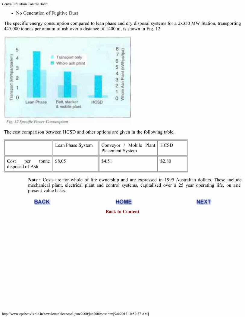
No Generation of Fugitive Dust
The specific energy consumption compared to lean phase and dry disposal systems for a 2x350 MW Station, transporting445,000 tonnes per annum of ash over a distance of 1400 m, is shown in Fig. 12.
The cost comparison between HCSD and other options are given in the following table.
Lean Phase System Conveyor / Mobile PlantPlacement System
HCSD
Cost per tonnedisposed of Ash
$8.05 $4.51 $2.80
Note : Costs are for whole of life ownership and are expressed in 1995 Australian dollars. These includemechanical plant, electrical plant and control systems, capitalised over a 25 year operating life, on a netpresent value basis.
Back to Content

Central Pollution Control Board
http://www.cpcbenvis.nic.in/newsletter/cleancoal-june2000/jun2000iss.htm[9/6/2012 10:59:28 AM]
Clean Coal Initiatives
ISSUES AND ACTION POINTS AT A GLANCE
Some of the salient issues and action points relating coal and environment interface in India as highlighted by DilipBiswas, Chairman, Central Pollution Control Board (CPCB) in his presentation in the Clean Coal Initiatives Roundtable,World Bank, Washington DC in June, 1996 are reproduced as follows:
COAL MINING SCENARIO
Share of opencast (surface) mining increasing. In 1995-96, out of 270 mt., 196 mt. (74%) coal came from opencastmines.
Major part of growth in demand in the past two decades was for thermal coal. India has large reserves of 40-45%ash coal, in shallow & thick coal seams, amenable to opencast mining. Current stripping ratio is around 2 cum perton of coal.
MAJOR ENVIRONMENTAL ISSUES IN COAL MINING IN INDIA
LAND DEGRADATION. Coal mines cover a total land area of 140,771 hectares (ha). During next 5 years, 57,000ha. additional land is needed, of which forest land is 13,000 ha.
AIR POLLUTION. SPM levels in the older coal mining areas of Jharia and Raniganj has increased 6 fold duringthe last 50 years due to mining and associated industrial activities.
Fires caused by indiscriminate mining in the past 100 years, affecting the Jharia coalfield, containing major CokingCoal reserves.
WATER POLLUTION. Mainly caused by the effluent discharge from old coal preparation plants set up along thebanks of Damodar river. The water pumped out of the mines is not a significant source of pollution.
Coal Transportation
Steep increase in coal transportation. beyond 1000 Km.
Distance 1993-94 2006-07 2009-10
Pit head 61 128 155
<500 Km 39 55 70
500-1000 km 22 47 60
> 1000 Km 43 170 215
(All figures in million tonne).

Central Pollution Control Board
http://www.cpcbenvis.nic.in/newsletter/cleancoal-june2000/jun2000iss.htm[9/6/2012 10:59:28 AM]
Issues in Transportation
Wasteful use of Rail Infrastructure in transporting high ash coal.
Coal routes are saturated or reaching saturation.
Innovative measures like, Engine on load system, own your wagon scheme and unit train operation.
Augmentation of rail transport will depend on commensurate investment.
Need for beneficiation
2001-02
Reduction of tonnage (mt) 11
Saving in transport cost (Usm$) 240
Saving in diesel consumption (KI) 63,750
Reduction in bottom ash (mt) 2
Reduction in fly ash (mt) 8
Reduction in CO2 (mt) 23
COAL BENEFICIATION STATUS
Only cooking coals are washed now.
Several proposals are ready for setting up washeries for non cooking coals in Talcher, Korba and North Karanpuracoalfields. A pilot plant at Bina opencast pithead in Singrauli coalfield is nearing completion.
Washability studies indicate reduction of ash level in raw coal from about 41-45% to 30-32% depending on coalquality and distance of transportation.
ENVIRONMENTAL ISSUES IN NON COKING COAL BENEFICIATION
Disposal of ash at the power plants vis-à-vis disposal of rejects from the pit head washeries.
Pit head power generation and transmission of electrical energy at high voltage through a national grid.
Cost and time for augmenting rail and coastal shipping transportation capacity, in case pit head generation option isrejected.
OPTIONS
Setting up of large pit head power stations.
Use of beneficiated coal in distant power stations.
Import of coal for coastal power plants.
Renovation and modernisation of old plants.
Adoption of clean combustion technologies.

Central Pollution Control Board
http://www.cpcbenvis.nic.in/newsletter/cleancoal-june2000/jun2000iss.htm[9/6/2012 10:59:28 AM]
Back to Content

ENVIS Centre, CPCB,Delhi, India
http://www.cpcbenvis.nic.in/newsletter/news.htm[9/6/2012 10:59:29 AM]
About Envis
Air Pollution
Water Pollution
Noise Pollution
Publications
News Letters
Annual Report
Highlights
News
Team
Home
News Letters
Water Quality Management in IndiaBio-mapping of Rivers - Case study Assam State - August-2005Sewage Pollution -February 2005Dioxin(PCDDs) And Furan(PCDFs) -December 2004Solid Waste Management in Slaughter House -September 2004Polycyclic Aromatic Hydrocarbons (PAHs) In Air And Their Effects On Human Health -November 2003Bio-monitoring of wetlands in wildlife habitats of India Part - I Bird Sanctuaries - July 2003Transport Fuel Adulteration - July 2003
Groundwater - July 2003R&D for Pollution Control CPCB Initiatives - June 2003
Inspection/Maintenance & Certification System for In-use Vehicles - May 2003
Alternative Transport Fuels An Overview-April 2003Odour Pollution and its Control - January 2003
Public Interest Litigations - December 2002
Climate Change - October 2002
Biodiesel As Automobile Fuel - September 2002
Benzene in Air and its Effect on Human Health - February 2002Air Pollution And Human Health-September 2001
Polychlorinated Biphenyls (PCBs) - December 2001
Environmental Management Plan Kanpur Urban Area- May 2001
Bio-Monitoring of Water Quality in Problem Areas - April 2001
Environmental Management System- February 2001
Common Effluent Treatment Plants - November 2000
Polluting Industries
Clean Coal Initiatives - June 2000
Bio-Mapping Of Rivers - March 1999
Auto Emissions - June 1999
Technologies for Pollution Control Industry - October 1999
Hazardous Waste Management - June 1998
Plastic Waste Management - September 1998
Municipal Solid Wastes - June 1997
Click here for LATEST Newsletters

ENVIS Centre, CPCB,Delhi, India
http://www.cpcbenvis.nic.in/newsletter/news.htm[9/6/2012 10:59:29 AM]
Cleaner Production Options for Pulp & Paper Industry - Sept 1997
Zoning Atlas For Siting Industries - June 1996
Bio-Monitoring of Water - September, 1995
Assessment and Development Study of River Basin - March 1995
Depletion of Ozone Layer and Its Implications - September 1994
Agro - based Industries - December 1994