cefic solvay guidelines pdfbr 1770 c-b-1-0602 - h2o2
TRANSCRIPT

7/24/2019 Cefic Solvay Guidelines Pdfbr 1770 C-b-1-0602 - h2o2
http://slidepdf.com/reader/full/cefic-solvay-guidelines-pdfbr-1770-c-b-1-0602-h2o2 1/48
HYDROG EN P EROXIDE
B ULK S TORAG E G UIDELINE
S O L V
A Y I N T E R O X ®
H2O2
S a f e t y
d o c u m
e n t a t i o n
7/24/2019 Cefic Solvay Guidelines Pdfbr 1770 C-b-1-0602 - h2o2
http://slidepdf.com/reader/full/cefic-solvay-guidelines-pdfbr-1770-c-b-1-0602-h2o2 2/48

7/24/2019 Cefic Solvay Guidelines Pdfbr 1770 C-b-1-0602 - h2o2
http://slidepdf.com/reader/full/cefic-solvay-guidelines-pdfbr-1770-c-b-1-0602-h2o2 3/48
3
Preface
The guideline has been developed by a task force comprising the following Companies:
• ATOFINA SA
• AUSIMONT SpA
• EKA Chemicals AB
• KEMIRA Chemicals OY
• F M C Foret SA
• DEGUSSA AG
• SOLVAY SA
From the start of this project the task force has benefited from the
guidance and helpful comments of Mr Bertil Lindeberg of the Swedish
Rescue Services Agency who could express the concerns of the
competent authorities and present the views of regulators.
The development of this guideline is in accordance with our Responsible
Care®
commitment to all stakeholders throughout the life cycle of Hydrogen Peroxide. Its purpose is to provide a single authoritative source
of guidance for controlling the risks of bulk storage which is intended to be
widely available to all stakeholders. It is the policy of our companies to
achieve the standards embodied in the guidance.
The document is maintained by the Technical Committee of the CEFIC
Hydrogen Peroxide sub group, the updated version can be found on
the CEFIC website: www.cefic.org.
Responsible C are ® is an international
initiative of the chem ical industry aim ed at
the continuous im provem ent of its perform ance in the areas of health, safety
and the environm ent.

7/24/2019 Cefic Solvay Guidelines Pdfbr 1770 C-b-1-0602 - h2o2
http://slidepdf.com/reader/full/cefic-solvay-guidelines-pdfbr-1770-c-b-1-0602-h2o2 4/48
4
Table of C ontents
Page
Purpose and scope of the guideline . . . . . . . . . . . . . . . . . . . . . . . . . . . . . . . . . . . . . . . . . . . . . . . . . . . . . 5
Definitions . . . . . . . . . . . . . . . . . . . . . . . . . . . . . . . . . . . . . . . . . . . . . . . . . . . . . . . . . . . . . . . . . . . . . . . . 6
1. Properties and classification . . . . . . . . . . . . . . . . . . . . . . . . . . . . . . . . . . . . . . . . . . . . . . . . . . . . . . . . 7
2. Hazards and consequences assessment . . . . . . . . . . . . . . . . . . . . . . . . . . . . . . . . . . . . . . . . . . . . . . 11
3. General guidelines for storage . . . . . . . . . . . . . . . . . . . . . . . . . . . . . . . . . . . . . . . . . . . . . . . . . . . . . 15
4. Hydrogen Peroxide storage tank . . . . . . . . . . . . . . . . . . . . . . . . . . . . . . . . . . . . . . . . . . . . . . . . . . . 18
5. Safety distances . . . . . . . . . . . . . . . . . . . . . . . . . . . . . . . . . . . . . . . . . . . . . . . . . . . . . . . . . . . . . . . . 23
6. Auxiliary equipments. . . . . . . . . . . . . . . . . . . . . . . . . . . . . . . . . . . . . . . . . . . . . . . . . . . . . . . . . . . . 25
7. Operations . . . . . . . . . . . . . . . . . . . . . . . . . . . . . . . . . . . . . . . . . . . . . . . . . . . . . . . . . . . . . . . . . . . 29
8. Emergency response. . . . . . . . . . . . . . . . . . . . . . . . . . . . . . . . . . . . . . . . . . . . . . . . . . . . . . . . . . . . 31
9. Management . . . . . . . . . . . . . . . . . . . . . . . . . . . . . . . . . . . . . . . . . . . . . . . . . . . . . . . . . . . . . . . . . . 34
Appendix 1 Decomposition kinetics of Hydrogen Peroxide . . . . . . . . . . . . . . . . . . . . . . . . . . . . . . . . 35
Appendix 2 Self Accelerating Decomposition Temperature . . . . . . . . . . . . . . . . . . . . . . . . . . . . . . . . 37
Appendix 3 Pressure burst: calculation overpressure radius . . . . . . . . . . . . . . . . . . . . . . . . . . . . . . . . 40
Appendix 4 Vent design methodology. . . . . . . . . . . . . . . . . . . . . . . . . . . . . . . . . . . . . . . . . . . . . . . . 41
Appendix 5 List of recommended materials . . . . . . . . . . . . . . . . . . . . . . . . . . . . . . . . . . . . . . . . . . . . 43
Appendix 6 Recommendations for the surface treatment . . . . . . . . . . . . . . . . . . . . . . . . . . . . . . . . . . 45

7/24/2019 Cefic Solvay Guidelines Pdfbr 1770 C-b-1-0602 - h2o2
http://slidepdf.com/reader/full/cefic-solvay-guidelines-pdfbr-1770-c-b-1-0602-h2o2 5/48
Purpose and scope of the
guideline“ The chemical industry aims to p lay a leading role in t he managem ent o f chemicals. It considers that it is
industry’s responsibility, in partnership with the authorities and other stakeholders, to ensure that its
chemicals are safely prod uced, used and disposed” – Chemical Management: a CEFIC
initiative, March 1999. This guideline on the BULK STORAGE OF HYDROGEN PEROXIDE
is an illustration of this commitment of CEFIC.
End-uses of hydrogen peroxide (HP) have undergone major development during
recent decades: more than two millions tons 100% of HP are used world-wide in
multiple applications, principally based on the oxidizing properties of this
product. Recognised as environmental friendly in so far as its by-products, water
and oxygen, do not represent any risk, HP remains nevertheless a chemical for
which storage and handling are safe only as long as strict safety principles are
known and respected by all.
The European producers of HP, members of the CEFIC peroxygen group, havedecided to combine their knowledge and experience in order to present
consistent recommendations on the bulk storage of HP. The purpose of this
guideline can be defined as following:
• To provide to users, authorities and other stakeholders information for carrying
out risk assessments for new or existing storage installations of HP. Although HP is
a well-known product, the existing literature on the product is wide but neither
complete nor homogeneous. This guideline, as a common source of information, should
minimise the risk of confusion and uncertainty among producers, users and regulators.
• To ensure the safety of the installations of producers and users of HP by realistic proposals concerning the
design and operation of HP storage installations. This guideline should be used as a basis for training and
increasing the know-how of all HP users.
• To set up minimum harmonised requirements for the storage installations, accepted by all the HP
producers members of the CEFIC.
The scope of the guideline is restricted to the following installations:
• Concentration of HP up to 70%. Higher concentrations of HP present other potential risks (e.g. self
explosion risk) and are only used in small quantities for minor and specialised applications.
• Fixed storage installations of HP. The transportation, packaging and uses of HP are not covered in this
guideline.
Considering the diverse nature of existing HP storage installations (different concentrations of product,
different size and location of the tanks), it is impossible to define fixed technical and organisational standardshaving to be used in all cases. Our methodology for the development of this guideline has consisted of
providing a risk assessment framework and the main basic elements for
• the design of the HP storage tank and its auxiliary equipment,
• the definition of the operating procedures related to the HP storage installation,
• the preparation of the emergency plan,
in order to reach the best level of safety for the personnel and the environment by the introduction of best
practicable means.
This guideline reflects our present best level of knowledge. It is not intended to replace the applicable
regulations but is complementary to them. The common commitment of the CEFIC HP producers is to maintain
an improved HP safety through the implementation of this guideline. All of these companies are ready to helpall stakeholders in the achievement of this objective.
5
7/24/2019 Cefic Solvay Guidelines Pdfbr 1770 C-b-1-0602 - h2o2
http://slidepdf.com/reader/full/cefic-solvay-guidelines-pdfbr-1770-c-b-1-0602-h2o2 6/48
D efinitionsFor the purpose of this guideline, the following terms are defined below:
Adequate: this term is used in the risk assessment of the chapter 3. It refers to the effectiveness of safety
features in preventing harm to people and environment and material damage, given the present state of the
art of the European producers.
Best practicable means: the techniques by which the greatest reduction of risk is obtained, taking into
consideration the economic aspect.
Concentration: the concentration in percent of HP in this guideline always refers to weight concentration.
HP: commercial aqueous solutions of hydrogen peroxide, with a concentration up to 70%.
Incompatible material: a material that, when in contact with HP, can cause hazardous reactions such as
decomposition or is itself adversely affected by contact with HP.
Minimum requirement: indicates that the item in question must be incorporated at every
HP storage installation according to the current guideline. Should technical or
organisational alternative be chosen, it has to be demonstrated that it brings a
comparable level of safety.
New installation: indicates a new site that includes a HP storage tank.
New storage tank: indicates a new HP storage tank, that
nevertheless may be installed in an existing site, with existing
constraints regarding the location which have to be
taken into consideration in the study of the bestpracticable solution.
Shall: indicates a mandatory requirement.
Should: indicates a recommendation or that which is
advised but not mandatory.
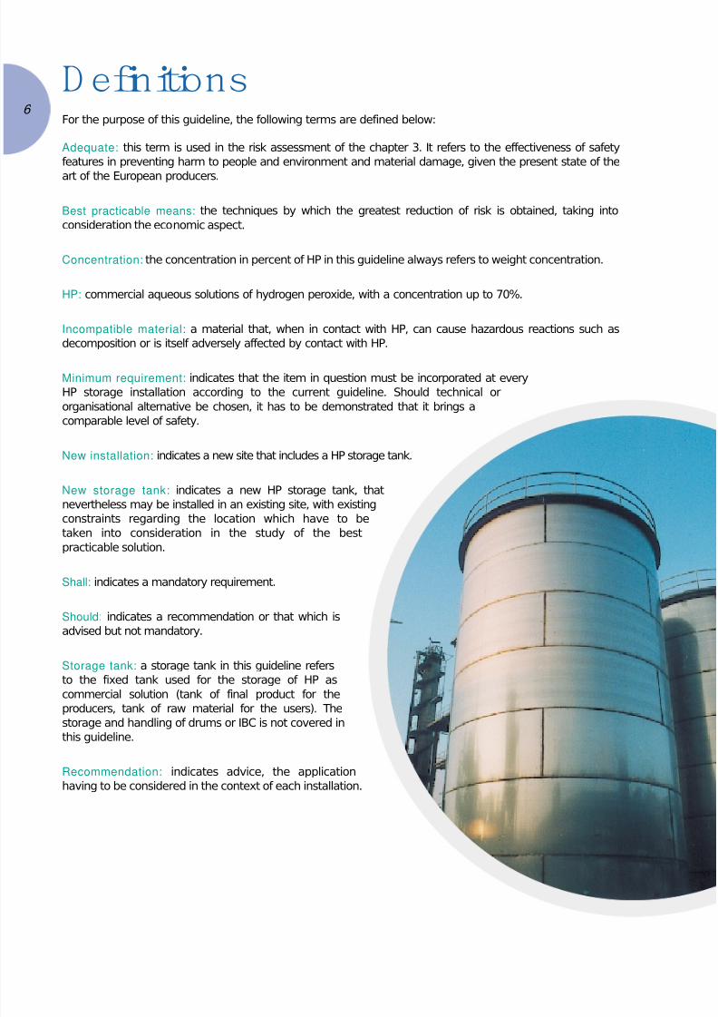
Storage tank: a storage tank in this guideline refers
to the fixed tank used for the storage of HP as
commercial solution (tank of final product for the
producers, tank of raw material for the users). Thestorage and handling of drums or IBC is not covered in
this guideline.
Recommendation: indicates advice, the application
having to be considered in the context of each installation.
6

7/24/2019 Cefic Solvay Guidelines Pdfbr 1770 C-b-1-0602 - h2o2
http://slidepdf.com/reader/full/cefic-solvay-guidelines-pdfbr-1770-c-b-1-0602-h2o2 7/48
150
140
130
120
110
100
20 4 6 80 100
1
14
1300
12
1100
1000
1
7
Conc H2O2 , w%
Conc H2O2 , w%
1.Properties and classification1.1 Physical datas and properties
HP is a clear, colourless liquid. It is only used in aqueous solution and is miscible with water in all proportions.At low concentrations, HP is odourless. It has a slightly pungent odour at higher concentrations.
Chemical formula: H2O2. Molecular weight 34.016
Density
The density of HP at different temperatures.
Density, kg/m 3
Boiling p oint
The boiling points of HP at atmospheric pressure.
Boiling po int at atm, °C

7/24/2019 Cefic Solvay Guidelines Pdfbr 1770 C-b-1-0602 - h2o2
http://slidepdf.com/reader/full/cefic-solvay-guidelines-pdfbr-1770-c-b-1-0602-h2o2 8/48
4.5
4.0
.5
.0
0
0 20 40 60 80 100
-10
-20
-30
-40
-50
-60
20 4 60 8 100
1
1 .
1 .
1.
.
4 °
2
8
Freezing point
HP at various concentrations have the following freezing points.
Freezing point , °C
Specific heat
The specific heat of HP at 25°C.
Heat capacity, °C
Vapour p ressure
Vapour pressure, kPa
The total vapour pressure (black
curve) over an H2O2 increases with
increasing temperature and
decreases with increasing H2O2
concentration. The partial pressure
of H2O2 (green curve) increases withincreasing temperature and the
H2O2 concentration of the solution.
Conc H2O2 , w%
Conc H2O2 , w%
Conc H2O2 , w%

7/24/2019 Cefic Solvay Guidelines Pdfbr 1770 C-b-1-0602 - h2o2
http://slidepdf.com/reader/full/cefic-solvay-guidelines-pdfbr-1770-c-b-1-0602-h2o2 9/48
9
2500
1
1000
00
1
Conc H2O2 , w%
Evaporation
Decomposition
Heat of evaporation
Transformation of HP to vapour requires less heat at high concentrations of H2O2.
Enthalpy at boiling point, kJ/kg
Comment: Calculations and tests confirm that there is always a decrease of the concentration of the HP in caseof adiabatic decomposition, even for concentration above 64%.(1)
Physical properties of typical HP
Concentration Density 20 °C Boiling point °C Freezing point °C Viscosityweight % kg/m3
Ns/m2 cp
0 (water) 1000 100 0 0.001002 1.002
35 1132 108 -33 0.00111 1.11
50 1196 114 -52 0.00117 1.17
70 1288 126 -40 0.00124 1.24
1.2 Chemical data and properties
HP is a very reactive substance and can undergo different types of reactions based on the following chemical
mechanisms:
• decomposition,
• redox reactions,
• reactions with organic materials.
Incompatibility with substances and materials should always be assumed unless the opposite has already beenproven.
Decomposit ion
In its commercial form, HP is a stable compound. pH of industrial peroxide is controlled by producers in order
to ensure a maximal stability of the HP. Decomposition occurs when HP is contaminated by e.g. metals.
Decomposition is affected by heat, pH and contamination. HP forms oxygen and water upon decomposition.
The reaction generates heat, which may be substantial.
H2O2 (l) → H2O (l) + 1 / 2 O2 (g)
98 kJ per mol H2O2
2882 kJ/kg
(1) Test report Eka Chemicals BC 2001-116
7/24/2019 Cefic Solvay Guidelines Pdfbr 1770 C-b-1-0602 - h2o2
http://slidepdf.com/reader/full/cefic-solvay-guidelines-pdfbr-1770-c-b-1-0602-h2o2 10/48
Impact of pH: both decrease and especially increase of the pH can have a negative impact upon stability. If the
pH of the HP is raised, this considerably increases the rate of decomposition. This may occur when alkaline
substances (e.g. caustic soda, sodium silicate, lime, hypochlorite, ammonia) are mixed with HP.
Homogeneous decomposition: accelerated decomposition may occur when HP is contaminated with
incompatible soluble substances, even when the level of contamination is low (a few ppm). This is called
homogeneous decomposition and occurs with a wide range of contaminants, especially salts of e.g. copper,
chrome, iron, vanadium, tungsten, manganese, molybdenum and platinum.
Heterogeneous decomposition: heterogeneous decomposition is the occasionally very rapid decomposition
of HP which occurs when it comes into contact with insoluble material. This occurs on contact with almost all
material, but the speed of the decomposition varies greatly, depending on the nature of the contaminant and
its contact surface.
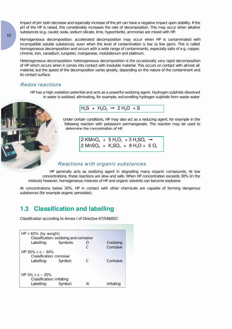
Redox reactions
HP has a high oxidation potential and acts as a powerful oxidizing agent. Hydrogen sulphide dissolved
in water is oxidized, eliminating, for example, evil-smelling hydrogen sulphide from waste water.
Under certain conditions, HP may also act as a reducing agent, for example in the
following reaction with potassium permanganate. The reaction may be used to
determine the concentration of HP.
Reactions w ith organic substances
HP generally acts as oxidizing agent in degrading many organic compounds. At lowconcentrations, these reactions are slow and safe. When HP concentration exceeds 30% (in the
mixture) however, homogeneous mixtures of HP and organic solvents can become explosive.
At concentrations below 30%, HP in contact with other chemicals are capable of forming dangerous
substances (for example organic peroxides).
1.3 Classification and labelling
Classification according to Annex I of Directive 67/548/EEC
HP ≥ 60% (by weight)Classification: oxidizing and corrosive
Labelling: Symbols: O Oxidizing
C Corrosive
HP 20% ≤ c < 60%Classification: corrosive
Labelling: Symbol: C Corrosive
HP 5% ≤ c < 20%Classification: irritating
Labelling: Symbol: Xi Irritating
H2S + H2O2 2 H2O + S
2 KMnO4 + 5 H2O2 + 3 H2SO4
2 MnSO4 + K2SO4 + 8 H2O + 5 O2
10

7/24/2019 Cefic Solvay Guidelines Pdfbr 1770 C-b-1-0602 - h2o2
http://slidepdf.com/reader/full/cefic-solvay-guidelines-pdfbr-1770-c-b-1-0602-h2o2 11/48
11
2.H azards and consequences
assessm ent2.1 Hazards
The potential hazards associated with a peroxide storage installation may be classified as follows:
• Decomposition, leading to
- vapour release
- pressure burst (if venting is inadequate)
• Loss of containment, leading to
- fire
- environmental and health hazards
Both vapour and condensed phase explosion hazards associated with HP alone (not contaminated by organic
materials) do not have to be considered in the case of bulk storage of usual concentrations below 70%.
Decomposit ion
There is always with HP a so called natural decomposition which is easy to handle (the product must never be
stored in a totally closed environment).
Considering a tank submitted to a higher rate of decomposition, it will release and disperse oxygen, steam and
HP fumes. The rate of release is variable, depending on the prevailing decomposition or boil up rate while the
total quantity released is depending on the initial inventory and HP concentration.
Decomposition may be initiated by an increase of temperature due to an external heat source (see § External
fire, vapour and condensed phase explosion) or by catalytic contaminants such as transition metal ions, strongacids or bases.
A convenient method of classifying all potential sources of contaminants is to assign each to a
level of catalytic activity, representing a decomposition rate increase of say 100, 1000,
10 000 times the normal. The effect of particular contaminants can vary enormously
depending on their nature and amount, the stabilisation of the product and other
factors. Some typical values are shown in appendix 1 (experimental results with
addition of iron or caustic soda). Based on experience, the contamination with
alkaline products represents the most critical scenario of decomposition to be
considered for HP storage tanks.
In order to obtain rate increases of 100 times or greater, it is necessary for
the peroxide solution to become grossly contaminated which should notnormally be possible in a well maintained storage. In such a case, any
increase in the rate is expected to come from a natural build up of metal
ions due to corrosion/erosion (especially in small tanks) or by the loss of
the effectiveness of the stabilisers. In these circumstances, the increase
in rate will typically range from 10 to 100 times the normal. This suggests
a 100 fold increase in the rate is a realistic maximum for catalytically
induced decomposition and a value of 1000 probably representing a
conservative value for the design of the safety vent. In case of extreme
contamination (e.g. alkaline), a higher rate can be anticipated.
A progressive decomposition may lead to safe venting of the resulting gas and
vapour, or a pressure burst of the vessel if the vent is not adequate. In the case of
the former, the only consequence will be that arising from a harmful peroxide vapouremission and the subsequent risk of exposure. In the event of a pressure burst, there
could be additional effects due to blast, missiles or hot liquid ejection.
7/24/2019 Cefic Solvay Guidelines Pdfbr 1770 C-b-1-0602 - h2o2
http://slidepdf.com/reader/full/cefic-solvay-guidelines-pdfbr-1770-c-b-1-0602-h2o2 12/48
Loss of containment
Fire hazard
HP and its oxidising properties could cause fire in the presence of organic substances or other combustible materials
(wood, paper, textiles, leather, ...). In the presence of H2O2, the intensity of a resulting fire will be greatly enhanced.
Be aware that fire may not start immediately due to the slow temperature increase but can occur after a delay.
Health hazard
HP poses risks to human health. It is irritant to the eyes and skin at concentrations above 5% and
causes burns above 20%. In the event that HP is swallowed, it can be harmful with increasing risk
of serious injury or fatality with increasing concentration.
HP is not classified as a carcinogen.
Inhalation of the vapour or mist will cause extreme internal irritation.
Occupational exposure limits:
• Time Waited Average (8-hour): 1 ppm (1,4 mg/m3)
• Short Term Exposure Limit (15 min): 2 ppm (3 mg/m3)
• Immediately dangerous to life or health concentration (IDLH): 75 ppm (105 mg/m3
).
Environment hazard
HP occurs naturally in the environment at levels of 0.1 – 4 ppb (air) and 0.001 – 0.1 mg/l (water).
Air
there is no regulatory limit industrial emission to air.
Water
HP is a substance which can be rapidly degraded but also has the potential to kill microorganisms and higher
species. Laboratory studies have shown that algaes are the most sensitive species and the predicted no effect
concentration is 10 ppb.
SoilHP decomposes readily to form water and oxygen.
External fire, vapou r and condensed phase explosion
These scenarios are not considered later in the guideline for the following reasons:
Vapour or condensed phase explosion of HP itself is impossible for concentrations below 74%: it is therefore
excluded from this guideline.
For other explosion scenarios, a precondition is the presence of organic material in the HP installation. This
precondition is generally avoided by the design and operating practises of an HP installation. In particular, there is
a strong focus on the avoidance of all contamination and incompatible materials including organic materials.
In principle, a mixture of HP and organics can lead to a condensed phase explosion for HP concentrations over40% and under special conditions (miscibility, concentration and dispersion of the organics). Such an explosion
releases an enormous quantity of energy (detonation), so that no safety relief equipment could prevent
a burst of the tank. For plants having to deal with this risk, special emphasis on prevention must
absolutely avoid organic contamination. The following requirements apply in such a case:
• segregation from organic materials for storage and drainage,
• procedures should be established that exclude absolutely the possibility of
unloading an organic material in an HP peroxide tank, and vice versa
(separated lines, double locked system, procedure of access control).
For fire, the effects on HP are likely to be minimal; the worst being a remote
chance of bursting a pipe. Only small tanks (and especially plastic tanks) could
be affected within a reasonable time-scale; a specific protection of the tankshould be studied in such a case. Bigger metallic tanks (> 50 m3) can stand a
fire for several hours because of the small exposed surface area/mass unit
(past incident experience is consistent with this view).
12

7/24/2019 Cefic Solvay Guidelines Pdfbr 1770 C-b-1-0602 - h2o2
http://slidepdf.com/reader/full/cefic-solvay-guidelines-pdfbr-1770-c-b-1-0602-h2o2 13/48
13
2.2 Assessment of probable consequences (2)
Decomposit ion
Release and dispersion
One of the consequences of a peroxide decomposition is the release of potentially harmful vapours into the
atmosphere. It is therefore necessary to determine dispersion characteristics so that the ground level concentrations
can be estimated and compared with the maximum allowable for exposure to give a contour of affected distances. The best available method is a computer based model. The source term for such a model includes:
• rate of release,
• duration/quantity of release,
• its temperature (and pressure) on release.
For a catalytically induced decomposition, calculations suggest the quantity of peroxide vapour released
(Ci = 70%) remains constant at about 60 kg H2O2 vapour/ton of product, the duration of release varies in the
range of 3 to 300 min (0.2 – 20 kg/min/t of product) depending on the level of catalytic activity.
For a decomposition initiated by fire exposure, the rate of vapour evolution is relatively low (about 0.4 kg/min/t
based on a 50 t tank) and may be assumed to be dominated by the selected decomposition case.
The vapour temperature on release is an important consideration in determining the initial
rise of the plume since the further it rises, the lower is the chance for it to drift
downwards at high concentrations.
The results of a simulation carried out using a recognised computer model for a
vessel containing 200 t of 70% HP undergoing a thermal decomposition at a rate
of 100 times the normal suggest that the initial buoyancy of the cloud emitted
through the vent is such that it rises very rapidly to 80 meters before it
disperses as a buoyant plume. The dispersion behaviour of the cloud at two
different meterological conditions also shows that the Immediate Danger to
Life and Health (IDLH) or Emergency Exposure Index (EEI) concentration is
never reached at the ground level even though the cloud may drift in excess
of several kilometers from the source of release.
A similar calculation with the assumption of a decomposition occurring at the
ground level (decomposition in the safety bund) suggests that HP vapour with
concentration above the IDLH may drift up to a distance of 300 meters away from
the emission source (100 t of 70%, decomposition at a rate of 1500 times the normal).
The models take no account of droplets either from condensation of vapour or
from emission at source or any subsequent decomposition that may occur in hot
vapour. Although in principle, droplets may occur over a wide range, incident
experience indicates that significant effects are not observed outside the immediate
vicinity of the source.
Pressure b urst
Storage tanks must be provided with emergency relief vent designed to relieve at low pressure. In the event
of a substantial decomposition, overpressurisation may occur leading to bursting of the vessel at or around its
yield pressures. In these circumstances damage could result from air blast and emission of hot reaction
products.
Air blast
In the event of an overpressure, a proportion of the released energy is always utilised to create the blast. This
proportion is difficult to set because of different failure modes. In the absence of information on failure modes,
no serious error is introduced if a value in the middle of the range is assumed (say 50%).
A method of estimating blast damage relies on the concept of TNT equivalence. Blast damage has to be
considered in the immediate vicinity of an explosion and is usually weak (window breakage, light inner wallrupture,...) below the overpressure circle of 50 mbar. Missile effects beyond this overpressure limit have a low
probability of occurrence. See example of calculation in appendix 3.
(2) CEFIC - Guidance note for the bulk storage of hydrogen peroxide – 1994

7/24/2019 Cefic Solvay Guidelines Pdfbr 1770 C-b-1-0602 - h2o2
http://slidepdf.com/reader/full/cefic-solvay-guidelines-pdfbr-1770-c-b-1-0602-h2o2 14/48
Liquid ejection
It is not possible to quantify effects which may result from hot liquid/vapour ejection with any order of accuracy.
However, it is not expected that these effects can extend to very great distances. Incident experience is
consistent with this view.
Loss of containment
Fire
If a fire occurs together with a leakage of HP, the HP decomposition and oxygen production will increase the
intensity in burning. This increase will be translated into a greater fire growth and higher flame temperatures
than if there were no oxidant present. An acceptable compromise for the estimation of this effect would be:
• a 50% increase in the flame height
• an increase of up to 100% in the surface emissive power of the flame to a maximum of ~250 kw/m2.
Contact w ith human
Damage to the eyes, skin in case of external contact; damage to bronchia in case of inhalation. This damage
might be irreversible or even fatal.
Environment
Can cause short term damage. However the H2O2 is not persistent and the environment can fully recover.
14

7/24/2019 Cefic Solvay Guidelines Pdfbr 1770 C-b-1-0602 - h2o2
http://slidepdf.com/reader/full/cefic-solvay-guidelines-pdfbr-1770-c-b-1-0602-h2o2 15/48
15
3.G eneral guidelines
for storage The purpose of this guideline is to act as a reference source for informing all concerned on how to achieve an
acceptable level of risk from bulk HP storage operations. The first step is to set the overall risk management
framework.
For each of the major hazard scenarios (accelerated decomposition and loss of containment), there are in
principle two stages during which damage to people, environment and material can be avoided. These stages
are prevention, and control/damage limitation (C/DL).
The guiding principle - according to experience - is that, although the many elements of prevention are always
necessary, they may not always be sufficient (a single defect in one element can be enough to initiate an
incident). Therefore, for the overall level of risk to be acceptable, there must be additional effective C/DL
measures.
In order to specify the extent of additional C/DL measures required, it is first necessary to explain the risk
categorisation philosophy upon which this guideline is based.
Three categories are identified as follows:
• Preferable: This is the highest standard and is expected to result in the lowest risk. It should be considered
as the specific target for new designs.
• Acceptable: This standard, whilst not as high as the above, is accepted for existing installations.
• Unacceptable: This standard represents an unacceptable risk to man and/or the environment and
improvements have to be made.
In the following sections, both main hazards are considered in turn and in each case, the available combinations
of C/DL measures are categorised as preferred, acceptable or unacceptable.
3.1 Hazards
Runaway decomposit ion
This event can occur if the rate of H2O2 decomposition is increased due to catalytic impurities. There are many
possible sources and they must all be excluded for prevention to be successful. Common examples are:
• inappropriate materials of construction (vessel, pipework, fittings, equipment components…)
• ineffectively passivated material of construction
• external contamination (airborne, maintenance, cross contamination, misdirected
chemical delivery).
The details of the necessary prevention measures for the above are given
in later chapters. The following table sets the standards for C/DL
measures. It is derived from an assessment of the risk of human injury
resulting from either the bursting of inadequately vented
equipment or exposure to vapour/liquid emanating from a
runaway decomposition. Definition of adequate venting,
separation and detection is given in chapters 4 and 5. A local
supply of water for first aid and spill dilution is always
compulsory.

7/24/2019 Cefic Solvay Guidelines Pdfbr 1770 C-b-1-0602 - h2o2
http://slidepdf.com/reader/full/cefic-solvay-guidelines-pdfbr-1770-c-b-1-0602-h2o2 16/48
Adequat ely Adequate Det ect ion and Status Comments
vented locat ion and Alarmseparation
Yes Yes Yes Preferred Standard for new installation
Yes Yes No Acceptable
Yes No Yes Acceptable Danger limited if productremains in the storage
No Yes Yes Acceptable
No No Yes Unacceptable
Yes or No No No Unacceptable
No Yes or No No Unacceptable
Loss of containment
As with runaway decomposition, this event can be realised in many ways, all of whose prevention must be
practised. Common examples are:
• overflow
• defective gaskets
• human error (e.g. valve alignment / flange tightening)
• mechanical failure e.g. hoses, connections
• pump seal failure
• pressure relief.
Later chapters detail the prevention measures. However, standards for control and damage limitation are
according to the following table, which is derived from an assessment of risk of damage to people and
environment in the event of a significant loss of containment.
Clarification of adequate containment, location, separation and detection is given in chapters 4 and 5.
Adequate Adequate Detect ion Status Comments
cont ainment locat ion and and alarmseparation
Yes Yes Yes Preferred Standard for new installations
Yes Yes No Acceptable
Yes No Yes Acceptable Emergency response
No Yes Yes Acceptable
Yes No No Unacceptable, High integrity emergency
except under procedure required and no
special conditions nearby combustible inventory
No No Yes Unacceptable A partial containment is
except under indispensable. The reliability
special conditions of the detection/alarm and
emergency plan has to be
proved
No Yes or No No Unacceptable
16

7/24/2019 Cefic Solvay Guidelines Pdfbr 1770 C-b-1-0602 - h2o2
http://slidepdf.com/reader/full/cefic-solvay-guidelines-pdfbr-1770-c-b-1-0602-h2o2 17/48
17
3.2 Prevention of incidents
The most important elements of incident prevention are as follows:
• The avoidance of all contamination
• The dedication of equipment to HP and avoidance of cross contamination by high integrity isolation from
other chemicals and utilities
• All equipment and fittings to be constructed from materials which are specifically approved and prepared
for HP use
• Equipment design standards to provide a high degree of mechanical integrity
• All equipment to be provided with appropriate vents
• Avoidance of contact with incompatible materials.
3.3 Detection and reduction of effects
The first step to reduce the effects of an incident is generally to detect any deviation as soon as possible:• measurement of the temperature of the storage, together with an alarm when it increases
• level indication and/or high level alarm on the tank, liquid detection
• regular inspection and control of the plant.
The following features will reduce the effect of an incident:
• Adequate venting of the storage tank and its accessories
• Safety shower and eyebath in the vicinity
• Use of personal protective equipments
• Location on a concrete surface provided with a retention basin
• Safety distances between the storage tank and adjacent buildings
• Supply of water for dilution of any spillage
• Pre-planning of emergency response, together with appropriate training and practise exercises.

7/24/2019 Cefic Solvay Guidelines Pdfbr 1770 C-b-1-0602 - h2o2
http://slidepdf.com/reader/full/cefic-solvay-guidelines-pdfbr-1770-c-b-1-0602-h2o2 18/48
4.H ydrogen Peroxide
storage tankMinimum requirements and recommendations concerning the design and the construction of HP storage tanks
are presented in this chapter. The diagram (p.22) representing a storage tank installation of HP presents
essential items of equipment and, in addition, some optional features. The minimum requirements shall be
installed in new storage tank installations and shall be considered for the evaluation and upgrade of existing
storage tanks. The choice of the optional features should be considered in each individual case taking into
account the local conditions.
Only atmospheric tanks should be used for HP. The tank can be either horizontal or vertical. It is essential that
the tanks are built only by firms which are able to meet the highly specific requirements for producing
compatible high integrity tanks and fittings. All HP tanks shall be of a mechanical quality and condition
appropriate for storing hazardous chemicals. In any case, the design of the storage tank installation should be
done together with a HP producer.
4.1 Temperature control
Temperature is the best parameter for the detection and analysis of the evolution of the situation in case of
decomposition of HP. For this reason, it is recommended to measure permanently this parameter, to set
adequate alarm and to monitor the evolution of the temperature in case of detected deviation (detection and
alarm in reference to the §3.1, runaway decomposition).
The homogeneity of the liquid phase cannot be guaranteed (principally in the case of heterogeneous
decomposition). We have to recognise that the measured temperature will not necessarily be representative
of the whole content of the tank. Therefore it may be necessary, according to the size of the vessel, to install
more than one temperature gauge. In order to get an adequate detection system, the recommendation for the
number of temperature gauges is:
• 1 if V < 100 m3,
• 2 if 100 m3 < V < 500 m3,
• 3 if 500 m3 < V < 1.000 m3,
• 4 if V > 1.000 m3.
Since the surface of the liquid should have the highest temperature, an alternative technology consists in
measuring the surface temperature (through infrared for instance); the number of measurement cells can be
reduced to one or two, even in the case of big storage tanks.
Alarm: the decomposition rate increases with the temperature, the alarm should therefore be set as low as
possible, in accordance with the local conditions. The first alarm can be set 5°C above themaximum normal liquid temperature; the emergency alarm a further 10°C higher
(refer to §8). Alternatively, the variation of the temperature of the liquid can be
considered for the evaluation of a decomposition situation with the
recommended alarm value of +1°C/h. Those recommendations are consistent
with the emergency response presented in §8.
Alarm switches and thermocouples must not be of the mercury type, and
the fluid used in the thermocouple well should be compatible with HP
(no oil).
18

7/24/2019 Cefic Solvay Guidelines Pdfbr 1770 C-b-1-0602 - h2o2
http://slidepdf.com/reader/full/cefic-solvay-guidelines-pdfbr-1770-c-b-1-0602-h2o2 19/48
19
4.2 Emergency relief vent
The st orage t ank must have an unobst ructed emergency vent (minimum requirement) to provide relief
in case of decomposition. The best way is to install a loose manhole cover assembly that opens freely at
low overpressure. It is desirable that the manholes are fitted with a loose wire mesh cover of appropriate
material of construction to prevent large objects such as inspection torches, safety helmets, pens or tools
falling into the tank.
The sizing of this emergency vent requires information on the worst decomposition scenario to
be taken into account. The following cases must considered for the evaluation of the
adequacy of the venting system (in reference to the §3.1, runaway decomposition):
• Case A: the contamination of the tank with strong decomposition
catalyst, typically alkaline products (e.g. caustic soda) can’t be
excluded. The safety vent has to be as big as technically possible:
total opening roof (e.g. weak welding seam).
• Case B: the above case is excluded but the contamination of
the tank with other decomposition substances has to be
considered. A totally empirical approach, based on the
analysis of past incidents, leads to a value of
200 cm2 / t H2O2 100%
• This value, independent of the HP concentration, is
commonly used for the design of the relief vent by the
users of HP.
• Case C: the storage tanks are located in highly
controlled areas, where the organisation and the
design of the plant reduces considerably the
probability and the severity of a contamination (storage
plant dedicated to HP for instance). A theoretical
approach can be developed in those defined cases by
the definition of the worst contamination scenario, taking
into consideration:
- the concentration of the stored product,
- the volume of the storage,
- the decomposition kinetic, based on the evaluation of the
acceleration of the decomposition induced by the contaminants by
laboratory tests.
Examples of this approach are presented in appendix 4.
In all cases, the design of the emergency relief vent should be developed together with a HP
producer.
In order to minimise the consequence of tank burst, it is recommended to ensure the rupture at the top of the
tank at as low a pressure as possible. One option is to ensure the frangibility of the roof (weak welding seam).
In case of severe overpressure not contained in spite of the relief vent (a two-phases flow through the venting
area in case of intensive decomposition is a factor of uncertainty in the design of the vent), the roof would open
and act as safety vent, preventing any explosion of the tank.
In the case of existing installations where these design rules could not be adapted, it is necessary during the
risk analysis that extra emphasis is placed on detection measures and emergency procedures (e.g. flooding or
dumping).
It must not be assumed that a vent designed with the above method is a guarantee of safety: it is a
recommendation which is intended to be used in conjunction with other preventive and emergency measures
and not instead of them.
7/24/2019 Cefic Solvay Guidelines Pdfbr 1770 C-b-1-0602 - h2o2
http://slidepdf.com/reader/full/cefic-solvay-guidelines-pdfbr-1770-c-b-1-0602-h2o2 20/48
4.3 Detection of a loss of containment
The HP is not corrosive towards those appropriate materials of construction described in this guideline. For this
reason, the probability of a leakage resulting from a corrosion of fixed pipes and connections is very low: a
visual and regular inspection of the plant should be sufficient. Plastic installation should be inspected with care
because of the risk of embrittlement. An overflow of the tank is much more likely to create a severe loss of
containment.
Level ind icator / h igh level alarm
To detect any overflow of the tank, a high alarm should be installed: this alarm can be simply a level switch. It
may automatically interrupt the filling of the tank in order to prevent any overflow.
A level indicator with high and low alarm may be preferred as far as it enables the monitoring of the peroxide
inventory. Standard technology of measurement can be used, e.g. DP cell, float, radar or ultrasonic sensors (as
long as all the materials of construction adopted are compatible with HP).
If the risk of overflow can’t be excluded, it must be ensured that it does not represent any risk for the personnel
and the environment: the overflow pipe must be directed into a safe location (e.g. catch bund).
Liquid detectionIn order to exclude any uncontrolled pollution of the environment with HP, liquid detection can in some cases be
necessary to warn the operating personnel and to enable timely corrective actions (for instance in case of
inadequate or small catch bund). Standard technology of liquid detection can be used (e.g. vibration limit switch).
4.4 Containment
The tank should be erected on a concrete surface. To avoid any contamination of the environment following a
leakage, the storage area should be provided with a retention bund. The adequate capacity of this bund
should be defined according to the local regulation; it should at least contain 110% of the capacity of the
biggest tank (if several tanks are located on the same area).
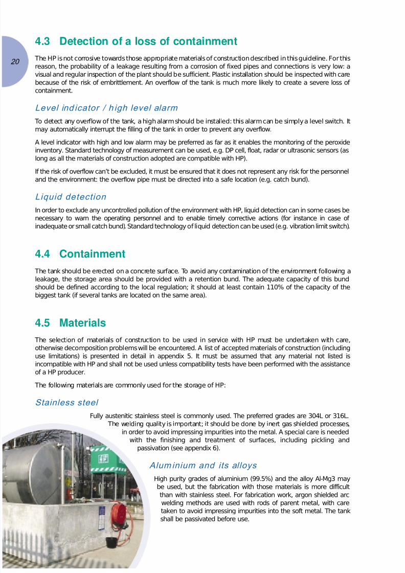
4.5 Materials
The selection of materials of construction to be used in service with HP must be undertaken with care,
otherwise decomposition problems will be encountered. A list of accepted materials of construction (including
use limitations) is presented in detail in appendix 5. It must be assumed that any material not listed is
incompatible with HP and shall not be used unless compatibility tests have been performed with the assistance
of a HP producer.
The following materials are commonly used for the storage of HP:
Stainless steel
Fully austenitic stainless steel is commonly used. The preferred grades are 304L or 316L.
The welding quality is important; it should be done by inert gas shielded processes,
in order to avoid impressing impurities into the metal. A special care is needed
with the finishing and treatment of surfaces, including pickling and
passivation (see appendix 6).
Alum inium and its alloys
High purity grades of aluminium (99.5%) and the alloy Al-Mg3 may
be used, but the fabrication with those materials is more difficult
than with stainless steel. For fabrication work, argon shielded arc
welding methods are used with rods of parent metal, with caretaken to avoid impressing impurities into the soft metal. The tank
shall be passivated before use.
20

7/24/2019 Cefic Solvay Guidelines Pdfbr 1770 C-b-1-0602 - h2o2
http://slidepdf.com/reader/full/cefic-solvay-guidelines-pdfbr-1770-c-b-1-0602-h2o2 21/48
21
Plastic material
Some plastic may be used for small tanks (preferably up to 30 m3) and for concentrations of HP up to 50%
weight. They must be very carefully selected and maintained. The mutual compatibility of the plastic and HP
must have been demonstrated and the safe lifespan established. High density polyethylene is preferred for the
tank. Particular care should be taken when using such materials as they are liable to degrade with time and are
easily damaged in case of collision. They shall not contain any pigments, mineral fillers or catalytic residues
incompatible with HP. If exposed to sunlight, they should contain suitable level of antioxydants and compatible
UV stabilisers (consult an HP producer).
4.6 Ancillaries
Breathing vent
A breathing vent must be installed in order to prevent any over- or under-pressure (minimum requirement). The
design of this vent should take into consideration the risk of contamination of the tank with particles present in
the air (if any). A suitable filter should be installed if necessary.
Emergency d ischarge (opt ional)
In the strategy of protection of the tank against overpressure, an approach can consist in emptying the tank
into the retention bund. This emergency discharge should be sized to prevent a bursting of the tank (in relation
to the size of the relief vent) and must be operable from a safe place.
Water source for coo ling o r flooding (optional)
A water source can be provided for safety reasons for cooling and flooding the tank in case of decomposition.
The water flow-rate is dependent on the size of the tank and on the other protection devices (relief vent and
emergency discharge). Deionised or potable water are preferred, but industrial water is acceptable. The water
must be fed at the top of the tank, through a dip pipe (for mixing purpose). This pipe must in normal position
be disconnected from the water feeding network (prevent contamination); the connection must be locked. It
must be operated from a safe location.
7/24/2019 Cefic Solvay Guidelines Pdfbr 1770 C-b-1-0602 - h2o2
http://slidepdf.com/reader/full/cefic-solvay-guidelines-pdfbr-1770-c-b-1-0602-h2o2 22/48
22
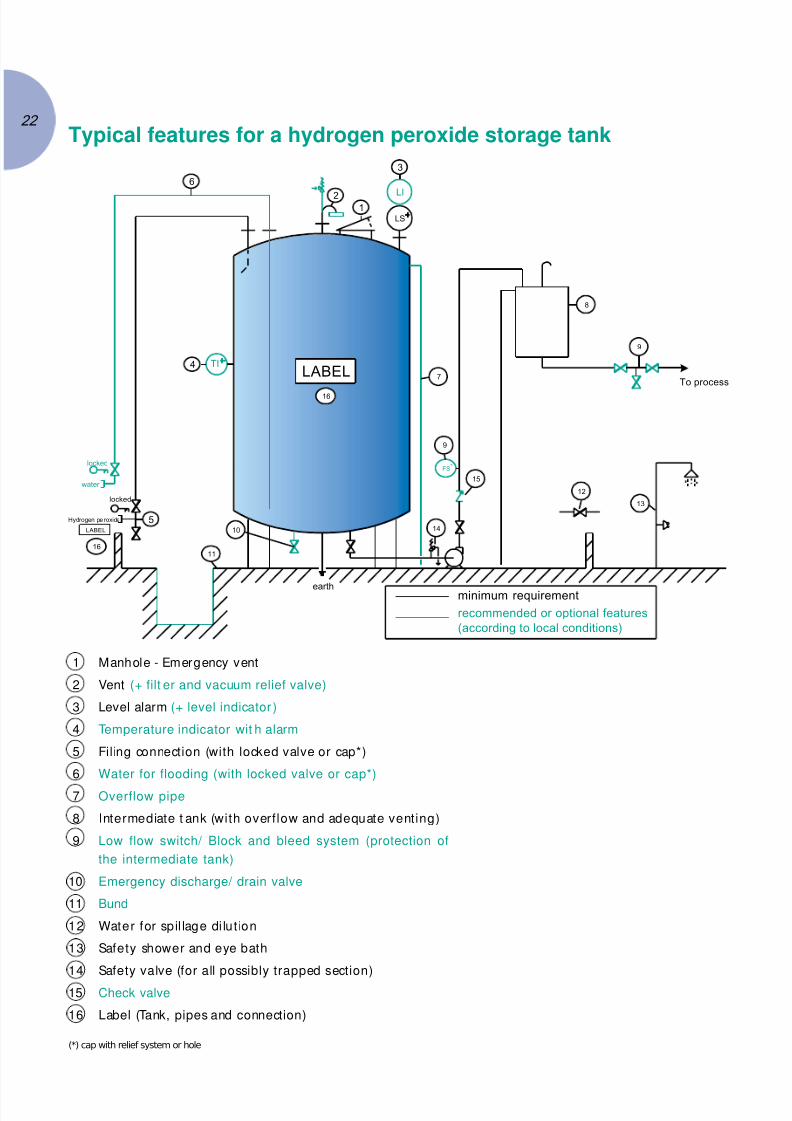
Typical features for a hydrogen peroxide storage tank
1 Manhole - Emergency vent
2 Vent (+ filt er and vacuum relief valve)
3 Level alarm (+ level indicator )
4 Temperature indicator wit h alarm
5 Filing connection (with locked valve or cap*)
6 Water for flooding (with locked valve or cap*)
7 Overflow pipe
8 Intermediate t ank (with overflow and adequate venting)
9 Low flow switch/ Block and bleed system (protection of
the intermediate tank)
10 Emergency discharge/ drain valve
11 Bund
12 Water for spil lage di lut ion
13 Safety shower and eye bath
14 Safety valve (for all possibly trapped section)
15 Check valve
16 Label (Tank, pipes and connection)
(*) cap with relief system or hole
LABELTI
12
3
LS
LI
6
4
5
11
10
earth
14
15
8
9
12
13
locked
water
locked
Hydrogen pe eroxid
LABEL
To process
FS
7
9
minimum requirement
recommended or optional features
(according to local conditions)
16
16

7/24/2019 Cefic Solvay Guidelines Pdfbr 1770 C-b-1-0602 - h2o2
http://slidepdf.com/reader/full/cefic-solvay-guidelines-pdfbr-1770-c-b-1-0602-h2o2 23/48
23
5.Safety distances5.1 Location
Storage tanks should be preferably placed outdoors, away from
heat sources and combustible materials. Tank location with
respect to other tanks and equipment containing other
chemicals must be considered carefully.
The tank and its accessories should be located
preferably in a secured zone, only accessible to
authorised personnel.
Piping and pumps should be located in
readily accessible areas, but where they will
not be easily damaged and where any
leaking HP solution from a damaged line or
flange will not fall on combustible materials
or working areas.
Underground storage tanks should not be
used. Indoors tanks or tanks on elevated
floors are not recommended. In the case of
indoors tanks, special attention during risk
assessment should be considered. Aspects to be
resolved are:
• vapour release, ventilation, evacuation and oxygen
accumulation in case of decomposition
• fire risks and drainage problems during loss of containment
• emergency relief venting to outside safe position
• emergency exits.
Tanks on elevated floors in existing installations are only acceptable if bunded and leakage control properly
arranged.
When several HP tanks are in the same storage area or retention basin, their separation distances should enable
to carry out all emergency actions and maintenance work to be performed correctly.
HP loading/unloading stations should be equipped with the adequate protection system to prevent mechanical
damages of the storage tanks by transport vehicles. The loading/unloading station should preferably be
isolated from other chemicals.
5.2 Safety distances
The determination of safety distances between atmospheric HP bulk storage tanks and objects for protection
should proceed by risk evaluation and be judged in each individual case. As worst case scenarios, pressure
burst of a tank and dispersion of HP droplets and vapour in decomposition situations should be considered.
This chapter aims to give all necessary information in order to proceed to the risk evaluation:
Fire
As mentioned in the chapter 2, the hazard related to an external fire should only be considered in the case of small
storage tanks. We recommend a distance of 7.5 meters between HP and combustible materials (3). This distance
refers to the risk of fire of the combustible materials. A non-combustible wall may be located adjacent to storagetank as an alternative to the safety distance.
(3) NFPA 430, 2000 Edition
7/24/2019 Cefic Solvay Guidelines Pdfbr 1770 C-b-1-0602 - h2o2
http://slidepdf.com/reader/full/cefic-solvay-guidelines-pdfbr-1770-c-b-1-0602-h2o2 24/48
Pressure burst of a tank
In case of inadequate venting, decomposition of HP could lead to a pressure burst of the tank. The
overpressure wave generated by this burst may represent a risk for the personnel and the neighbour
installation (domino effect). An example of calculation of this overpressure as a function of the distance to
the tank is presented in appendix 3. Both chosen limits, 140 and 50 mbar, are considered in our approach
as hazard limits for the equipment / buildings and for human beings. The calculation of the distances
related to those overpressure values in each individual case should help to determine:
• the risk to the neighbouring installation in case of pressure burst
• the safe distance for the personnel in case of decomposition.
Emissions / d ispersion in case of decomposit ion
As mentioned in chapter 2, calculations of droplet behaviour suggest, that majority of the air-borne liquid
would fall within a 20 – 30 meters radius from the vessel. In addition the dispersion behaviour of the HP cloud
emitted through the safety vent also shows, that the IDLH value of 75 ppm is never reached at the ground level
even though the cloud may drift in several kilometres from the source of release. If the decomposition occurs
on the ground rather than in a vessel, then vapour dispersion distances could be extended further.
Gas and liquid phase explosion risk are not considered for the evaluation of the safety distance for the reasons
mentioned in the chapter 2.
24
7/24/2019 Cefic Solvay Guidelines Pdfbr 1770 C-b-1-0602 - h2o2
http://slidepdf.com/reader/full/cefic-solvay-guidelines-pdfbr-1770-c-b-1-0602-h2o2 25/48
25
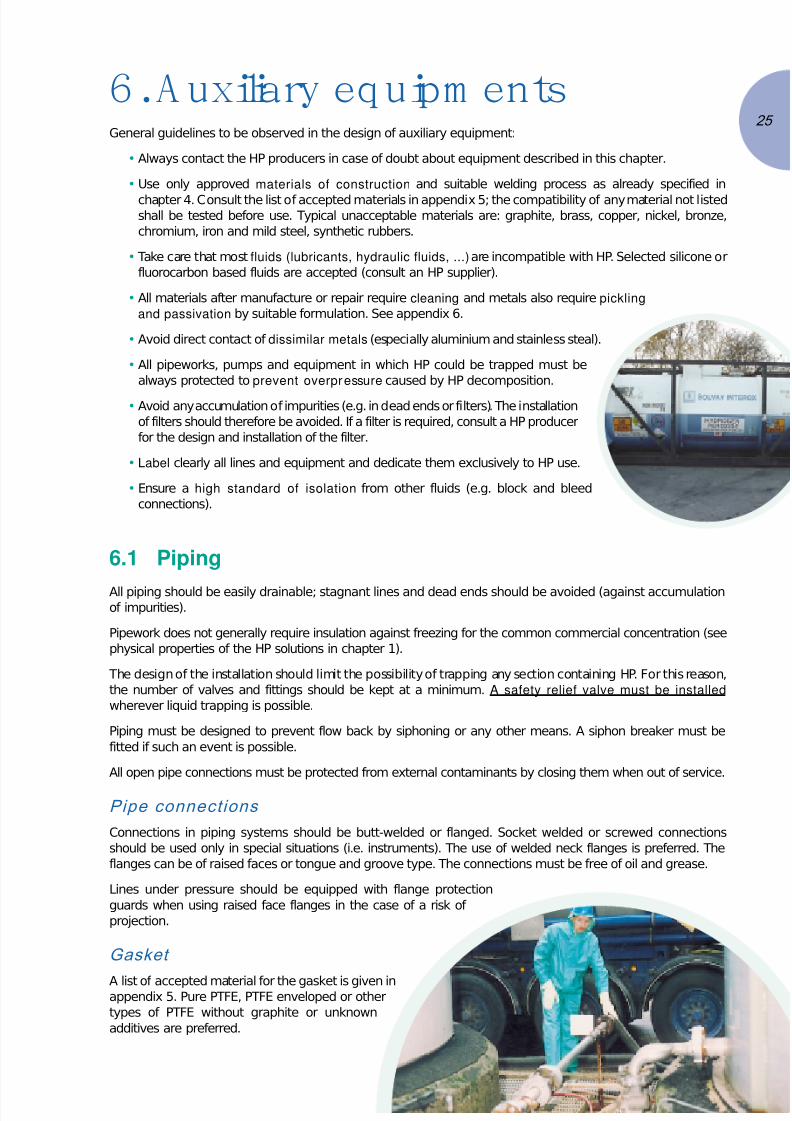
6.Auxiliary equipm entsGeneral guidelines to be observed in the design of auxiliary equipment:
• Always contact the HP producers in case of doubt about equipment described in this chapter.
• Use only approved materials of construction and suitable welding process as already specified in
chapter 4. Consult the list of accepted materials in appendix 5; the compatibility of any material not listedshall be tested before use. Typical unacceptable materials are: graphite, brass, copper, nickel, bronze,
chromium, iron and mild steel, synthetic rubbers.
• Take care that most fluids (lubricants, hydraulic fluids, ...) are incompatible with HP. Selected silicone or
fluorocarbon based fluids are accepted (consult an HP supplier).
• All materials after manufacture or repair require cleaning and metals also require pickling
and passivation by suitable formulation. See appendix 6.
• Avoid direct contact of dissimilar metals (especially aluminium and stainless steal).
• All pipeworks, pumps and equipment in which HP could be trapped must be
always protected to prevent overpressure caused by HP decomposition.
• Avoid any accumulation of impurities (e.g. in dead ends or filters). The installation
of filters should therefore be avoided. If a filter is required, consult a HP producer
for the design and installation of the filter.
• Label clearly all lines and equipment and dedicate them exclusively to HP use.
• Ensure a high standard of isolation from other fluids (e.g. block and bleed
connections).
6.1 Piping
All piping should be easily drainable; stagnant lines and dead ends should be avoided (against accumulationof impurities).
Pipework does not generally require insulation against freezing for the common commercial concentration (see
physical properties of the HP solutions in chapter 1).
The design of the installation should limit the possibility of trapping any section containing HP. For this reason,
the number of valves and fittings should be kept at a minimum. A safety relief valve must be installed
wherever liquid trapping is possible.
Piping must be designed to prevent flow back by siphoning or any other means. A siphon breaker must be
fitted if such an event is possible.
All open pipe connections must be protected from external contaminants by closing them when out of service.
Pipe connections
Connections in piping systems should be butt-welded or flanged. Socket welded or screwed connections
should be used only in special situations (i.e. instruments). The use of welded neck flanges is preferred. The
flanges can be of raised faces or tongue and groove type. The connections must be free of oil and grease.
Lines under pressure should be equipped with flange protection
guards when using raised face flanges in the case of a risk of
projection.
Gasket
A list of accepted material for the gasket is given inappendix 5. Pure PTFE, PTFE enveloped or other
types of PTFE without graphite or unknown
additives are preferred.

7/24/2019 Cefic Solvay Guidelines Pdfbr 1770 C-b-1-0602 - h2o2
http://slidepdf.com/reader/full/cefic-solvay-guidelines-pdfbr-1770-c-b-1-0602-h2o2 26/48
Safety relief valves
The safety valve must allow the release of any gas generated as a
result of the normal decomposition of non contaminated HP
(standard commercial solutions). The generated flow of gas is
low; for this reason, the minimum commercial size of safety
valve is sufficient. The case of the large diameter and/or long
pipes must be studied individually. Pay attention to the
compatibility of all the materials of construction of the safetyvalve (especially the multiple internal elements).
It is useful to standardise set pressures and dimensions for
each installation.
The discharge of the safety valve should be directed into a safe
location.
Valves
The criteria for the choice of the valves (including check valves) are:
• no possibility of trapping HP in any position of the valve
• compatible materials: this recommendation can be particularly
difficult to observe because of the multiple elements in the valves:
casing, shaft, gaskets, rings. Check all the elements of the valve
in contact with the fluid.
• no need for lubricant.
Ball valves: a degassing hole must be drilled in the ball so that, while in the off position, the channel through the
ball can be connected with the upstream liquid side. Those valves are commonly used for diameters below
DN150. The hole diameter should be 3 mm minimum.
Globe valves: commonly used for all diameters.
Butterfly valves: used for diameters over DN150.
Diaphragm, plug and gate valves are not recommended.
Hoses
Hoses should be minimised in number and length, dedicated and properly
connected. It is preferred to reserve hoses for use only on a temporary basis
(install fixed pipes whenever possible).
Choose carefully the type of hoses and their materials. In case of doubt, ask
an HP producer (see material list in appendix 5).
6.2 Pumps
Centrifugal pumps are usually used for HP. Volumetric pumps are also acceptable.
The use of other types of pumps should be discussed with an HP producer.
General recommendation: an emergency stop should be possible from a safe location
(control room or local). Materials of construction should be selected according to the table
in appendix 5.
Centrifugal pum ps
Shaft seal: single mechanical seal (recommended material: SiC/SiC. Alternatives: glass filled PTFE, alumina
ceramic). O-ring: PTFE or perfluoroelastomers.
Avoid double mechanical seals (risk of HP trapping) and packed glands (risk of HP decomposition,
incompatibility with lubricants).
Precautions should be taken to avoid pump operation against a dead end that may cause rapid temperature rise.
26

7/24/2019 Cefic Solvay Guidelines Pdfbr 1770 C-b-1-0602 - h2o2
http://slidepdf.com/reader/full/cefic-solvay-guidelines-pdfbr-1770-c-b-1-0602-h2o2 27/48
27
Volumetric pumps
Diaphragm, piston and gear pumps can be used. It is important to make a careful choice of materials of
construction and intermediate fluid. The pump manufacturer should be informed about the risk associated with HP.
Membranes should be in PTFE, stainless steal or zirconium. Only compatible materials of construction, even on
the non-peroxide side, should be allowed in case of membrane rupture.
The piston should be a PTFE gland packing-plunger.
Protect volumetric pumps against overpressure generated by a closed discharge line. In case of installation of
a safety valve, the discharge should preferably be connected to the suction side of the pump.
6.3 Intermediate tank
To prevent any back-flow, a mechanical break upstream of the contact with any other product must be
installed (minimum requirement).
An intermediate tank between the storage tank and the injection in the process is the best way to realise this
break: do not rely on check valves or instrumentation (flow switch and isolation valve for instance).
This intermediate tank should have:
• a limited size
• an overflow, to prevent any back-flow in the HP tank
• adequate venting, preferably as big as technically possible
• a temperature measurement (optional)
• a block and bleed system on the discharge line to the process.
The intermediate tank can also be used as a dosing tank for the HP.
6.4 Instrumentation
Users should seek advice from HP producers for the determination of the
most appropriate type of instrument.
Take care that instruments do not involve trapping risks and that materials of
construction are approved.
If conveying fluids are used in the measuring sensors, the fluid must be
compatible to allow possible equipment failures.
Instrument air must be oil free and dry.
6.5 Safety facilities
Safety shower and eyebath must be installed in the vicinity. They must be tested periodically.
A water source must be available for a dilution of spills and leaks. All water supplies should be
easily accessible, clearly labelled and available at all times with protection against freezing.

7/24/2019 Cefic Solvay Guidelines Pdfbr 1770 C-b-1-0602 - h2o2
http://slidepdf.com/reader/full/cefic-solvay-guidelines-pdfbr-1770-c-b-1-0602-h2o2 28/48
6.6 Unloading section (for users)
HP must be preferably unloaded using a self-priming centrifugal pump; this pump must be dedicated to the
use of HP. The unloading by dry air (oil free) or nitrogen is nevertheless acceptable; in this case, the gas system
should be equipped with a proper filter, pressure reducing valve, safety valve and pressure gauge (do not use
engine discharge).
In order to prevent contamination (unloading of another product), a physical barrier must be established
(minimum requirement), for instance by a cap or a valve closed with a key, under the responsibility of a
responsible member of the personal of the plant.
Coupling: a dedicated coupling is recommended.
Pipes must be dedicated to HP: no cross connection, no common header.
Label clearly the unloading zone and pipes (particularly the connection point for unloading).
Any spillage resulting from a disconnection of the hoses must not represent any danger: it can be recovered in
the bund of the storage or be evacuated after dilution with a large quantity of water.
6.7 Dilution installationDilution of the product, - before, after or even during storage, is often practised because of the low
concentration used in many applications, in order to reduce the transportation cost and/or the size of the
storage tanks.
In case of a dilution before or during storage, use only demineralised or deionised water (typically, the
requirement on the conductivity is lower than 1 µS/cm). It is not allowed to use steam condensate or boiler feed
water. In case of a dilution after storage (or for direct use, without storage), the requirements on the quality of
the water are not so high (respect the requirements of the process). It is
recommended to perform stability tests to validate the quality of the
water (those tests can be done by the supplier / producer).
The transfer line for demineralised water should beconstructed with materials compatible with HP (this
recommendation is mandatory for all sections of the
line from where HP back flow can’t be excluded). The
design should ensure the impossibility to return HP
into the water distribution network (don’t rely on a
check valve or on a simple isolation valve). The
configuration of the pipe connections between
HP and demineralised water lines should include
an intermediate draining valve (block and bleed
system).
28

7/24/2019 Cefic Solvay Guidelines Pdfbr 1770 C-b-1-0602 - h2o2
http://slidepdf.com/reader/full/cefic-solvay-guidelines-pdfbr-1770-c-b-1-0602-h2o2 29/48
29
7. O perations7.1 Supply
The unloading of bulk HP must be organised so that the
following hazards are specifically avoided:
• Delivery of HP to any destination other than its
intended dedicated tank or via any route other than its
dedicated pipework and associated equipment.
• Delivery of any other substance to the HP tank or via the
HP pipework and associated equipment.
• Contamination of the HP during the unloading procedure.
• Overfilling of the HP storage tank.
• Leakage or spillage of the HP, and resulting contact with people or environment.
• Overpressure and/or underpressure beyond the limits of equipment.
In order to achieve these objectives, the following features will normally be required:
• Validation of the product before unloading (check that it is indeed HP).
• Unloading will preferably be by means of a suitable dedicated pump (either on the vehicle or the
recipients installation). Alternatively, air or nitrogen can be used provided that they are clean, dry, filtered,
oil free, equipped with adequate overpressure protection and that lines are blown out prior to unloading.
• The unloading procedure includes provision for confirmed identification of unloading point, prestart-up
check for correct valve alignment and absence of defects, dedicated capped hoses, full personal
protective equipment (except breathing apparatus) for people involved, check of adequate ullage in
receiving tank, and continued supervision during unloading.
• The responsibility for the unloading operation must rest with the installation management throughout.Unloading operations must be performed by trained personnel.
7.2 Dilution
Dilution of HP potentially has several adverse effects on its stability. In particular, the very act of dilution will
reduce the concentration of stabilisers in the HP and so their effectiveness. In addition, even low levels of
contaminants which are inevitably present in water can have the ability to cause serious destabilisation. Dilution
will also cause the pH to increase.
The effects of any dilution operation on stability must be assessed in advance.
HP suppliers will normally offer advice or assistance if requested.
7.3 Handling
Handling operations should preferably be carried out in a dedicated, ventilated and clean area, free of
combustible materials and heat sources. In accordance with normal industrial hygiene, activities such as
smoking, eating and drinking should be prohibited.
Handling operations should be allied to approved methods and procedures, improvisation being forbidden.
The following key principles should be embodied in operations:
• The need for care, especially in prevention of spills and contamination of the HP
• Scrupulous cleanliness
• Good housekeeping

7/24/2019 Cefic Solvay Guidelines Pdfbr 1770 C-b-1-0602 - h2o2
http://slidepdf.com/reader/full/cefic-solvay-guidelines-pdfbr-1770-c-b-1-0602-h2o2 30/48
• Avoidance of all contact with incompatible materials
• Equipment being kept closed to keep out contamination, while still permitting decomposition gases to
escape
• Equipment being restricted to what is specifically suitable, clean, passivated (where appropriate), and
labelled as for HP only
• Avoidance of any trapping of HP during a long period, even if the section in question is equipped with
an overpressure protection
• Avoidance of use of inappropriate equipment by imposition of a rule to the effect that, whatever is not
specifically approved, is forbidden
• After use, portable equipment to be rinsed thoroughly with good quality water and drained
• Decontamination by immediate drenching of anything which is contacted by HP
• As a minimum, the requirement is for goggles and gloves for any operation. Increased levels of protective
equipment where required for splashing or vapour exposure (see safety data sheet)
• No leather gloves
• Avoid leather shoes where there is a risk of contact with HP
• Proximity of and awareness of safety showers/adequate water supplies/eyewash bottle
• Once removed, HP must not be returned to the tank.
7.4 Maintenance
All maintenance work on an HP installation should be controlled by a formal permit
procedure which assesses the tasks to be undertaken, the current working conditions,
and specifies appropriate safety precautions.
Because of the special engineering features required for materials of construction and
fabrication techniques necessary for HP systems, great care has to be exercised in
repair, modification, cleaning or other maintenance operation. In particular the
person(s) undertaking the work must have the necessary competences to ensure
that only suitable materials, correctly pre-treated and fitted, are used.
For the replacement of fittings gaskets or other accessories, it must be
ensured that only like for like replacement occurs. Experience shows that
even minor apparently inconsequential differences can result in serious
safety problems e.g. minor grade changes in gasket materials, or
subcomponent change in a measurement probe.
Storage installations should be routinely inspected for signs of leakage,
damage, disrepair and proper functioning of components. In addition safety
equipment must be regularly proof tested.
7.5 Disposal
All disposal operations must be carried out in compliance with all applicable regulations in such
a way that the safety of people and environment is protected. The main options are as follows:
• HP can be flushed to sewer as long as it is diluted sufficiently to not present a hazard in the drains. It is
recommended to keep the concentration of the diluted product below 5% for safety purpose. In addition
HP can be destroyed on a waste water treatment plant (to avoid adversely affecting its operation, the HP
concentration at the entry point of a biological treatment plant should be below 100 ppm).
• The HP can be prevented from entering the environment and disposed of as a dangerous waste. This may
be done by absorption on a non combustible material e.g. sand, vermiculite, or by decomposition. In
these cases particular care has to be taken with respect to the safety aspects.
30

7/24/2019 Cefic Solvay Guidelines Pdfbr 1770 C-b-1-0602 - h2o2
http://slidepdf.com/reader/full/cefic-solvay-guidelines-pdfbr-1770-c-b-1-0602-h2o2 31/48
31
8. Em ergency response
8.1 Emergency planning
In sites where there are HP tanks, it is imperative that an emergency response plan is available.
The emergency response plan, at least, shall provide directions for:
• actuation of an alarm signal
• actions to be taken in case of dangerous situations with respect to HP, such as decomposition, fire, spillage
• allocation of responsibilities
• procedures for notification of responsible management and authorities
• evacuation procedures (e.g. warning system, evacuation routes, registration and care of evacuees).
All personnel directly or indirectly involved in the storage and use of HP shall be familiar with the emergency
response plan. The emergency response plan, where appropriate, shall also be discussed with and made available
to the local authorities. This is especially important for the parts concerning off-site help (e.g. fire-brigade, hospital).
The emergency response plan shall be checked and updated in regular intervals. The effectiveness of the emergency
procedures shall regularly be tested, ensuring that the people involved experience such an event once a year.
8.2 Runaway decomposition
There are two aspects of runaway decomposition, which must be taken into account. These are, the dynamics
of its auto accelerating nature and the variety of its potential consequences. Firstly, its auto accelerating nature
is such that in its early stages, it can occur very slowly, even imperceptibly. However as the decomposition
progresses, it will go faster and faster, becoming hotter and hotter and eventually generating large volumes of
gas and vapour in a very short period. Secondly, the rate of acceleration of a particular runaway decomposition
event can be extremely variable, depending primarily on the nature of the causal contamination.
A particular decomposition emergency can develop over a period of e.g. few minutes or e.g. hours or even
longer. At the point of discovery of a runaway decomposition, it is not at all obvious how much time may be
available before the attainment of maximum rate of decomposition.
General ground rules
The main principle to be applied is to ensure the safety of all personnel within range as the top priority. Actions
to protect the environment or save product and/or equipment must be a secondary objective. Upon detection
of a decomposition, the emergency procedure must adopt the following principle lines of action:
• Removal of unnecessary/untrained personnel from the zone of potential danger (criteria to be defined
by discussion),
• Communication of state of emergency to other personnel and authorities as appropriate,
• If safe to do so, intervention by trained and protected personnel.
The intervention guidance is summarised below in the form of some important general ground rules followed
by the available tactical choices:
1. It is essential to have a pre-planned emergency procedure.
2. All intervention actions must be with full protective clothing and by trained personnel.
3. In case of doubt or the unexpected, everybody should go to a safe location.
4. All HP out of containment (overflow, emission, dumped) should be diluted as much as possible in
accordance with chapter 7.5.5. Authorities must be notified in the event of environmental exposure.
6. Medical contact with specific HP treatment knowledge.

7/24/2019 Cefic Solvay Guidelines Pdfbr 1770 C-b-1-0602 - h2o2
http://slidepdf.com/reader/full/cefic-solvay-guidelines-pdfbr-1770-c-b-1-0602-h2o2 32/48
Response options
In the event of a decomposition emergency the choice of response usually depends on two main factors:
• Knowledge of the actual rate of decomposition
• The size of the installation.
Knowledge of the decomposition rate may be conveniently classified as follows:
A. Visible emission from vent or audible gas escape from vent or temperature increase above ~15ºC above
the normal liquid temperature. These are all signs of a decomposition, which may well be imminent and
in all probability cannot be stopped (in case of conflicting evidence, audible and visual indicators should
take precedence). The safe choices are evacuation and eventually remotely actuated emptying/dousing.
B. Temperature increases less than ~15ºC above ambient temperature. Subject to caveats about the
reliability of temperature indication, this is an incipient decomposition for which intervention time may
well be available (until type A indications develop). In this case, investigation, local dousing/emptying or
spray cooling may be considered. For small tanks even stabiliser addition may be effective.
C. Other knowledge e.g. known contamination, excessive bubbling of the liquid, indirect evidence such as unusual
behaviour of process or equipment. In this case, all options are available until type B or A indications develop.
Comments
Concerning tank size, in general, to increase the size of the tank will inhibit the effectiveness of the addition of
stabilisers or any external cooling of the tank. However, there is no uniquely defined relationship or correlation.
Stabiliser addition is unlikely to be effective unless an engineered means of mixing is incorporated. Spray
cooling is unlikely to be effective except in the early stages of decomposition and then not for large tanks.
In the event of a large vapour emission, the emergency plan must address the safety of the people in a
downwind location. They should either escape in a direction perpendicular to the wind direction, or be indoors
with windows and doors closed and preferably upstairs at the downwind side of the building. Water curtains
may be deployed by the fire brigade in case of decomposition at the ground level (e.g. decomposition in the
bund after dumping of the product) in order to limit the dispersion of the HP vapours; the risk of overpressure
of the tank should be considered for the position of the fire brigade (in relation with the safety distances).
8.3 Loss of containment
In case of a loss of containment, the emergency response must consider the risks against the person and the
environment, as well as the specific risk of fire, or even explosion in the event of contact with flammable
materials if confined e.g. in drains, pits or closed collection tanks.
Fire fighting
HP will not burn, although it can initiate combustion of combustible
materials and contribute to an increased ferocity of burning. The
application of water is recommended for all fires involving HP. In the
event of HP being exposed to an adjacent fire, water spray cooling of the
HP equipment may be applied to prevent accelerated decomposition,
but only if this can be achieved from a safe location. This
recommendation applies mainly to small tanks; for
larger tanks, experience shows that it is unlikely that
a surrounding fire would cause an hazardous
increase of the temperature of the HP.
In all cases personnel protective
equipment is required. If there is a
risk of explosion, water application
must be from behind protection.
32

7/24/2019 Cefic Solvay Guidelines Pdfbr 1770 C-b-1-0602 - h2o2
http://slidepdf.com/reader/full/cefic-solvay-guidelines-pdfbr-1770-c-b-1-0602-h2o2 33/48
33
Environment
HP should not be discharged to water courses or soil. If necessary, spillages should be contained, by use of an
inorganic absorbent such as sand or vermiculite, to prevent entry to the environment.
In case of discharge to the environment, the appropriate authorities should be notified without delay. Refer to
chapter 7.5 for details.
UNDER NO CIRCUMSTANCES SHOULD HP BE DISPOSED OF BY TRANSFER TO ANY VESSEL. ESPECIALLY
NOT USE ANY GENERAL PURPOSE WASTE TANKERS OR VACUUM TRUCKS.
First aid
HP is corrosive to the skin and mucous membranes and can cause severe damage to the eyes while direct contact.
At any place where HP is stored or handled, appliances must be available for extensively washing skin and eyes.
Unless mentioned otherwise, in case of an accident any person may carry out the following actions, whether or
not trained in first aid.
➜ Skin exposure
• Rinse with copious amounts of cold water
• If skin burns develop, rinse continuously with cold water for
15 minutes
• Immediately remove contaminated clothes, avoid own skin
contact (place clothes in water to prevent spontaneous
ignition)
• Cover burnt skin with sterile gauze
• Consult a doctor
➜ Eye exposure
• Immediately rinse with lukewarm, slowly running water,
during which the eyes shall be kept open; this shall bemaintained for at least 15 minutes
• In case of serious eye injuries, continue irrigation during
transport of the patient to an ophthalmologist
• Immediately consult an ophthalmologist
➜ Swallowing
• Do not induce vomiting
• Rinse mouth and give plenty of water to drink only if the
patient is conscious
• Keep patient quiet and warm
• Consult a doctor immediately
➜ Inhalation
• Remove the patient to fresh air and keep him quiet and warm
• In case of symptoms of irritation of the respiratory tract
and the lungs (coughing, shortness of breath), allow the
patient to rest in a half upright position
• Administer oxygen 8-10 litres per minute
(trained personnel only!)
• Consult a doctor immediately
In case of any doubt, refer to the safety data sheet (SDS).

7/24/2019 Cefic Solvay Guidelines Pdfbr 1770 C-b-1-0602 - h2o2
http://slidepdf.com/reader/full/cefic-solvay-guidelines-pdfbr-1770-c-b-1-0602-h2o2 34/48
9.M anagem ent
The management shall appoint a sufficient number of well-instructed personnel to manage, to supervise and
to handle the HP.
The management shall
• provide the technical means and facilities to store the HP in a correct and safe manner
• provide accurate and unambiguous instructions for proper handling of HP
• ensure adequate and sufficient maintenance, inspections and operating procedures
• ensure emergency and fire-fighting plans.
The management shall audit the above mentioned elements regularly. Accidents or incidents shall be
effectively investigated. Corrective actions must be implemented, their efficiency must be checked afterwards.
The management shall ensure that no modification of the installation and operating practises can be carried
out without authorisation from competent responsible persons.
The management shall take care that the personnel involved in storage and handling shall be given adequate
instruction and training, both in safe and proper handling of HP, and in emergency procedures to deal with
spillage, contamination, decomposition, fires, ingestion, inhalation, skin and eye contact. Refreshment courses
should be given at least once a year.
34

7/24/2019 Cefic Solvay Guidelines Pdfbr 1770 C-b-1-0602 - h2o2
http://slidepdf.com/reader/full/cefic-solvay-guidelines-pdfbr-1770-c-b-1-0602-h2o2 35/48
35
Appendix 1
D ecom position kinetics of H ydrogen Peroxide
Reaction KineticsH2O2 H2O (l)+ 1 / 2 O2 (g) ∆H = - 98 kJ/mol = - 2.882 kJ/kg
d[H2O2]/dt = -k [H2O2]
with: k = 0.81* 107 * kF * e(-10357/T) min-1
for uncontaminated product kF = 1
Decomposition kinetics are accelerated by:
• Contaminants (Fe, NaOH, ...) : increase of kF
• Increase of temperature
• Increase of pressure (limitation of water vaporisation thus increase of temperature)
For contaminated product, see example of kF values in the following tables (k values at 25 °C).
Experimental results with addition of Fe3+
Experimental results with addition of caustic soda instabilised 70% HP
Iron content(mg/kg)
0.12
0.377.76
15.52
31.04
38.81
46.6
10
20
k x 108
min -1
0.95
37.56
9.42
64.55
912.5
6763
4476
21760
kF
1.46
4.611.6
14.4
98.9
1398
10366
6861
33360
Comments
Standard
technical grade
70% HP
Unstabilized
70% HP
NaOH 100%(kg/m3)
pH k x 108
min -1
kF
0 0.55 3 4.6
2 4.85 105 160
5.8 5 295 452
7 5.45 863 1322
12 5.8 2283 3499
17 6 35200 53950
26.4 6.2/6.45 70083 107415
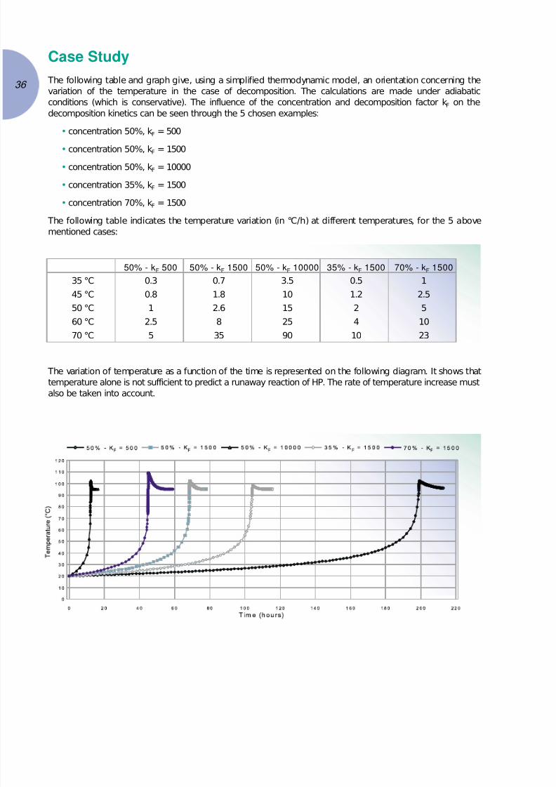
7/24/2019 Cefic Solvay Guidelines Pdfbr 1770 C-b-1-0602 - h2o2
http://slidepdf.com/reader/full/cefic-solvay-guidelines-pdfbr-1770-c-b-1-0602-h2o2 36/48
Case Study
The following table and graph give, using a simplified thermodynamic model, an orientation concerning the
variation of the temperature in the case of decomposition. The calculations are made under adiabatic
conditions (which is conservative). The influence of the concentration and decomposition factor kF on the
decomposition kinetics can be seen through the 5 chosen examples:
• concentration 50%, kF = 500
• concentration 50%, kF = 1500
• concentration 50%, kF = 10000
• concentration 35%, kF = 1500
• concentration 70%, kF = 1500
The following table indicates the temperature variation (in °C/h) at different temperatures, for the 5 above
mentioned cases:
50% - kF 500 50% - kF 1500 50% - kF 10000 35% - kF 1500 70% - kF 1500
35 °C 0.3 0.7 3.5 0.5 1
45 °C 0.8 1.8 10 1.2 2.5
50 °C 1 2.6 15 2 5
60 °C 2.5 8 25 4 10
70 °C 5 35 90 10 23
The variation of temperature as a function of the time is represented on the following diagram. It shows that
temperature alone is not sufficient to predict a runaway reaction of HP. The rate of temperature increase must
also be taken into account.
36

7/24/2019 Cefic Solvay Guidelines Pdfbr 1770 C-b-1-0602 - h2o2
http://slidepdf.com/reader/full/cefic-solvay-guidelines-pdfbr-1770-c-b-1-0602-h2o2 37/48
37
Appendix 2
Self Accelerating D ecom position
Tem perature
The Self Accelerating Decomposition Temperature (S.A.D.T.) is a very important parameter which is continually
used in peroxygen technology. It is also often not fully understood.
HP and most peroxygen compounds are basically unstable, continuously decomposing with the evolution of
heat. Material in a container will therefore progressively self-heat if the rate of heat loss to the surroundings is
less than the rate of heat generation. As the temperature of the material increases, the decomposition rate and
the rate of heat evolution increases. An accelerating reaction results. The S.A.D.T. of a system is the
temperature of the surroundings above which a given quantity of material in a container of a given size and
shape will generate an accelerating reaction. It is specific to that particular container and to that particular
weight of the material. S.A.D.T.‘s are, however, specified for many unstable substances in Product Descriptions
and in Storage and Transport Regulations without any description of the container’s size and shape, or of
amount of its contents. These S.A.D.T.‘s are derived from the standard maximum sized package and quantityof material which are used for products of that particular class. These conditions must be known before these
standard S.A.D.T.‘s can be used as anything more than a general guide to systems which involve different
amounts of materials in containers of different size and shape.
In figure 1 the straight line AB shows the rate of heat loss from a container and its contents to the surroundings,
as a function of temperature. The curved line CD shows the relationship between the material’s temperature
and its rate of heat evolution.
Points E and E1 are temperatures of the surroundings, and if the container and its contents are at these
temperatures they will obviously lose no heat.
Point G is the point at which temperature of the container and its contents are in equilibrium with surroundings
at temperature E.
If the temperature of the surroundings increases to E1 there is a new temperature loss line A1B1, which is
tangential at point H to the heat evolution line CD. Container and contents will just remain in equilibrium with
the surroundings when the temperature of the surroundings reach a temperature of E1. Any further increase in
temperature of the surroundings and contents and container will progressively self-heat in an accelerating
mode, irrespective of their initial temperature.
The surroundings temperature E1, is the S.A.D.T. of the system.
Point J is the Point of No Return. The temperature at point J is the Temperature of No Return (T.N.R.). Material
above this temperature, put into a container in surroundings of temperature E, will self-heat in an accelerating
mode.
At the S.A.D.T. the temperature of the Point of No Return coincides with the temperature at which the material
and container are in equilibrium with its surroundings.
Deterioration of stability will move curve CD to the left, lowering the S.A.D.T. and vice versa. Increases of size
and proportionally, contents in a series of containers of given geometry will reduce the slope of the straight
line AB, giving progressively lower S.A.D.T.‘s. Changes in geometry which decrease the surface/volume ratio
will also reduce the slope of AB and the S.A.D.T.
As HP is always decomposing and evolving heat, there will be a maximum size of storage tanks of a given
geometry which can be filled with HP of a particular stability. As tanks increase in size, the amount of
contamination which can be tolerated before the S.A.D.T is reached gets smaller and smaller. There will also
be a maximum temperature for the HP which can be filled into a tank of given size and shape, in surroundings
at a particular temperature.
In practical systems, considerations of S.A.D.T. do not have any great influence on the choice of storage tank
sizes. Standard commercial grades of HP can be stored in tanks of over 1000 tonnes capacity in the hottest
climates.

7/24/2019 Cefic Solvay Guidelines Pdfbr 1770 C-b-1-0602 - h2o2
http://slidepdf.com/reader/full/cefic-solvay-guidelines-pdfbr-1770-c-b-1-0602-h2o2 38/48
S.A.D.T.‘s and equilibrium temperatures of tank contents with the surroundings at the S.A.D.T., have been
calculated and plotted in figure 2. For strengths of HP between 35% and 70%, the decomposition/heat rates
change very little and a single rate equation can be used to give adequate accuracy. Very high strength
materials do require modified rate equations. The S.A.D.T. and T.N. R. for a 17,5 tons I.S.O. tank full of 86%
with kF = 1 are 68°C and 80°C, compared with 81°C and 94°C for 35% - 70% material.
Figure 1 - Typical S.A.D.T. diagram
C A A1
J
H
G
D
E E1
B B1
Heat Loss
from Container
and
Heat Generated
by Material
Heat Gained
by Container
Temperature
Equilibrium Tem p.
of C ontainer in
Surroundings of
Tem p. EEquilibrium Tem p. and Tem p.
of N o R eturn for C ontainer
in S urroundings at the S.A.D .T. E1
38
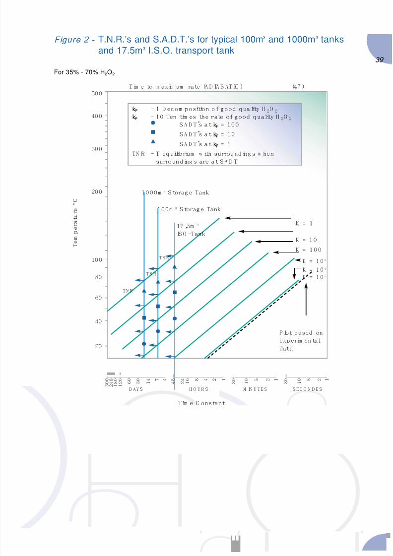
7/24/2019 Cefic Solvay Guidelines Pdfbr 1770 C-b-1-0602 - h2o2
http://slidepdf.com/reader/full/cefic-solvay-guidelines-pdfbr-1770-c-b-1-0602-h2o2 39/48
39
Figure 2 - T.N.R.’s and S.A.D.T.’s for typical 100m3 and 1000m3 tanks
and 17.5m3 I.S.O. transport tank
500
400
300
2001000m
3
S torage Tank
kF - 1 D ecom position o f good quality H 2O 2
kF - 10 Ten tim es the rate of good quality H 2O 2
S A D T’s at kF = 100
S A D T’s at kF = 10
S A D T’s at kF = 1
TN R - T equilibrium w ith surround ings w hen
surrounding s are at S A D T
Tim e to m axim um rate (A D IA B AT IC ) (47 )
For 35% - 70% H2O2
Tim e C onstant
T e m
p
e r a t u r e
° C
100m 3 S torage Tank
17 ,5m 3
IS O -Tank
K = 1
TN R
TN R
TN R
D AY S H O U R S M IN U TES S EC O N D E S
K = 1 0
K = 100
K = 1 0 3
K = 1 0 4
K = 1 0 5
P lot based on
exp erim ental
data
100
80
60
40
20
3 0 0
2 4 8
1 8 0
1 2 0
6 0
3 0
1 4 7 4
4 8
2 4 1 6 8 4 2 1
3 0
1 0 5 2 1
3 0
1 0 5 2 1

7/24/2019 Cefic Solvay Guidelines Pdfbr 1770 C-b-1-0602 - h2o2
http://slidepdf.com/reader/full/cefic-solvay-guidelines-pdfbr-1770-c-b-1-0602-h2o2 40/48
Appendix 3
Exam ple of calculation of the overpressure
related to a burst of H P tank using the
TN T equivalence m ethod
The following calculation method is only indicative. Other methods or criteria can be used to estimate the
consequences of a tank burst.
We consider the following overpressure values as important for the determination of safety distances:
140 mbar: Lower limit for the major destruction of buildings. Considered also as a limit of lethality for
people, not because of the effect of the overpressure on human beings, but because it
corresponds to an empirical limit for the risk of projection of material.
50 mbar: Minor destruction of buildings (glass, light inner wall or weak structures). Limit for small injuries
caused by glass breakage.
According to a chart, we can determine the “reduced distance” λ related to those both cases:
λ = R / 3√m
R : distance to the centre of explosion
m : equivalent kg TNT
λ = 10 for 140 mbar λ = 25 for 50 mbar
For the calculation of m, we use the following calculation principle:
Energy released during the pressure burst (estimated by isoenthalpic expansion energy of the gaseous phase):
∆E = PV . [1- (P/Pa)(1-γ )/ γ
] / (γ -1) (in Joules)P : rupture pressure (Pa)
Pa : outside pressure (atmospheric - 1,013.105 Pa)
V : gas phase volume of the tank (m3)
γ = 1.4 (ratio of specific heats)
50% of ∆E is considered to be utilised for the blast.
1kg TNT = 3.72 MJ .
Caution: in the above calculation, the rupture pressure should not be confused with the design pressure.
Rupture pressure of low pressure tank can be much higher than the design pressure.
With this calculation we can consider different explosion cases, in relation with the volume and the rupturepressure of the tank. Only the gas volume is taken into consideration for the calculation; it is assumed that the
tank is filled with 50% HP.
Tot al volume (m3) 500 100 20 5
Volume V gas (m3) 250 50 10 3
P rupture (bar g.) 0.2 1.0 1.0 1.0
∆E (MJ) 3.8 4.4 0.9 0.3
m ~ TNT (kg) 0.51 0.6 0.1 0.04
R 140 mbar 8 m 8.4 m 5 m 3.4 m
R 50 mbar 20 m 21 m 12 m 8.5 m
This calculation should be performed in each individual case for the determination of the effect of a pressure
burst of the tank (if considered to be possible). The distances resulting from the calculation should be
considered in the safety management of the plant (protection of the personnel and equipment).
40

7/24/2019 Cefic Solvay Guidelines Pdfbr 1770 C-b-1-0602 - h2o2
http://slidepdf.com/reader/full/cefic-solvay-guidelines-pdfbr-1770-c-b-1-0602-h2o2 41/48
41
Appendix 4
M ethodology for designing H P storage vents
This calculation approach (4) can be used in the case of a foreseeable maximum contamination scenario.
According to this approach, the required vent area can be obtained by the following relation:
A = f (c, p, kF) ≈ 0.35 ( c / 100-c) (kF / √p )
with A vent area cm2/t H2O2 100%
c H2O2 concentration % weight
p max. operating storage pressure mbar g
kF H2O2 decomposition rate factor (see appendix 1)
c is known. p is the maximum allowed pressure; it shall be less than or equal to the design pressure.
The difficulty is to estimate the decomposition rate factor kF.
This methodology takes into account:
• the storage volume and the HP concentration
• the storage max. operating pressure
• the HP quality
• the types and max. quantity of contaminants.
The both last parameters must be evaluated case by case and depend on:
• the connections with the storage
• the prevention equipment (dedicated coupling ...)
• the operators experience (producers/customers ...).
Calculation examples
p = 50 mbar
kF = 1.500
- c = 35 wt % A = 40 cm2/t H2O2 100%
- c = 50 wt % A = 74 cm2/t H2O2 100%
- c = 70 wt % A = 173 cm
2
/t H2O2 100%
Comparison with other calculation methods
The results obtained with this kF value are coherent with other usually used values, e.g.:
➜ 200 cm2/t H2O2 100% (recommended for small storage tanks)
➜ Factory Mutual method: d = a * V0,493
with d : diameter of the vent (cm)
V : volume of the HP stored (m3)
a : constant depending on the HP concentration (see following table)
(4) Protection of HP storage tank against overpressure – J C. Adrian, H. Lagarrigue - 1993

7/24/2019 Cefic Solvay Guidelines Pdfbr 1770 C-b-1-0602 - h2o2
http://slidepdf.com/reader/full/cefic-solvay-guidelines-pdfbr-1770-c-b-1-0602-h2o2 42/48
HP concent rat ion “ a” values Vent size
wt % cm2 / t H2O2 100%
35 4,77 ⊃ 42
50 6,74 ⊃ 56
70 15,8 ⊃ 205
Proposed methodology
42
Risk
analysis
Laboratory study
complementary
tests
t max. quantity of H2O2 100% in storage
a total vent area (cm2)
Evaluation of the worst
stability at H2O2 which could
be sent to the
storage
max. kF evaluation
V ≤ 100m3 V > 100m3
if kF < 1500then kF = 1500
A = f (c, p, kF)
A = f (c, p, kF) a = At
av = Atif a < a100
a = a100
Evaluation of types of contaminants and max.quantity which could be
accidentally added into thestorage
max. conc. of contaminant
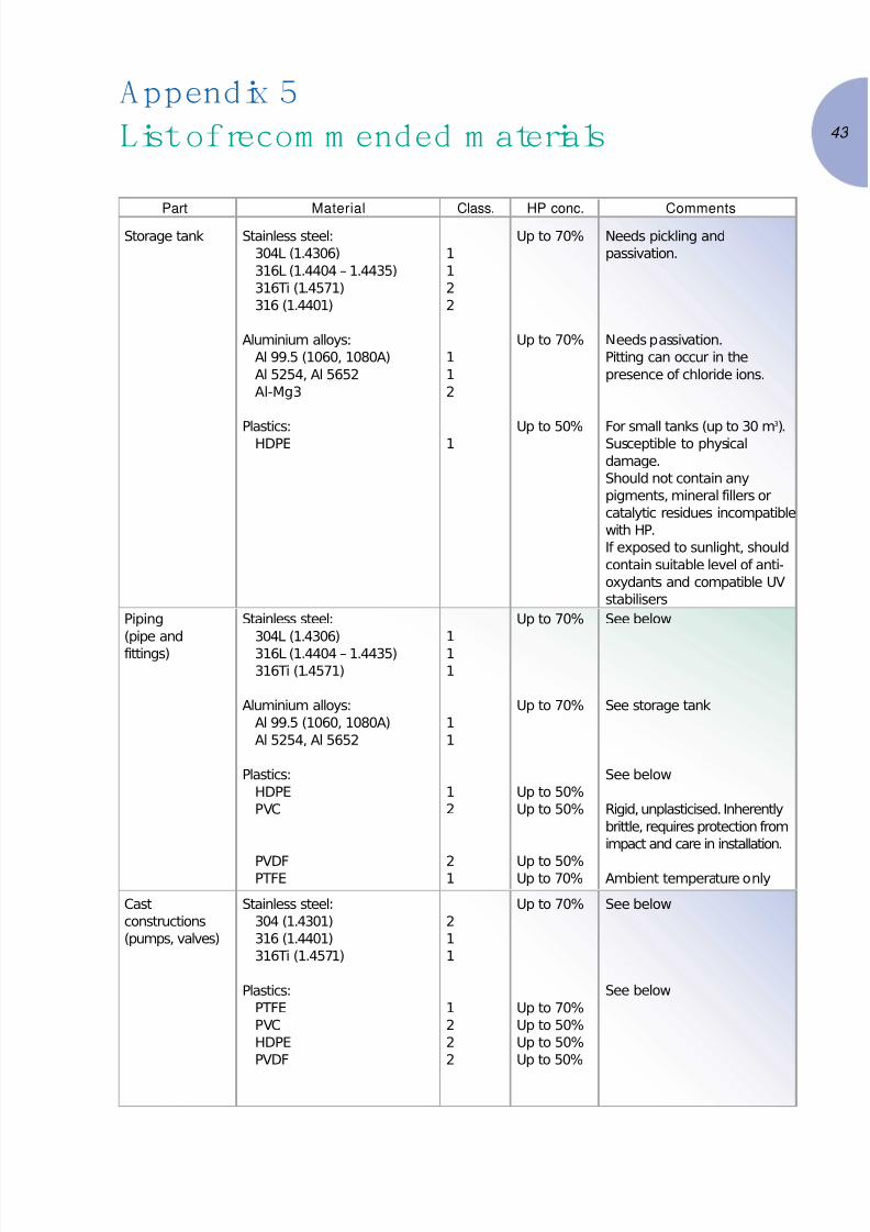
7/24/2019 Cefic Solvay Guidelines Pdfbr 1770 C-b-1-0602 - h2o2
http://slidepdf.com/reader/full/cefic-solvay-guidelines-pdfbr-1770-c-b-1-0602-h2o2 43/48
43
Appendix 5
List of recom m ended m aterials
PartStorage tank
MaterialStainless steel:
304L (1.4306)
316L (1.4404 – 1.4435)
316Ti (1.4571)
316 (1.4401)
Aluminium alloys:
Al 99.5 (1060, 1080A)
Al 5254, Al 5652
Al-Mg3
Plastics:HDPE
Class.
1
1
2
2
1
1
2
1
HP conc.Up to 70%
Up to 70%
Up to 50%
CommentsNeeds pickling and
passivation.
Needs passivation.
Pitting can occur in the
presence of chloride ions.
For small tanks (up to 30 m3
).Susceptible to physical
damage.
Should not contain any
pigments, mineral fillers or
catalytic residues incompatible
with HP.
If exposed to sunlight, should
contain suitable level of anti-
oxydants and compatible UV
stabilisers
Piping
(pipe and
fittings)
Stainless steel:
304L (1.4306)
316L (1.4404 – 1.4435)
316Ti (1.4571)
Aluminium alloys:
Al 99.5 (1060, 1080A)
Al 5254, Al 5652
Plastics:
HDPE
PVC
PVDFPTFE
1
1
1
1
1
1
2
21
Up to 70%
Up to 70%
Up to 50%
Up to 50%
Up to 50%Up to 70%
See below
See storage tank
See below
Rigid, unplasticised. Inherently
brittle, requires protection from
impact and care in installation.
Ambient temperature only
Cast
constructions
(pumps, valves)
Stainless steel:
304 (1.4301)
316 (1.4401)
316Ti (1.4571)
Plastics:
PTFE
PVC
HDPE
PVDF
2
1
1
1
2
2
2
Up to 70%
Up to 70%
Up to 50%
Up to 50%
Up to 50%
See below
See below

7/24/2019 Cefic Solvay Guidelines Pdfbr 1770 C-b-1-0602 - h2o2
http://slidepdf.com/reader/full/cefic-solvay-guidelines-pdfbr-1770-c-b-1-0602-h2o2 44/48
Classification:
1: Material that are fully compatible with HP and suitable for a long term contact.
2: Materials that are satisfactory for repeated short term contact with HP – performance
dependent upon grade of material used.
PartGasket
MaterialPure massive PTFE
Expended PTFE
Glass loaded PTFE
Perfluoroelastomer
Class.1
1
1
2
HP conc.Up to 70%
Up to 70%
Up to 70%
Up to 50%
CommentsPure massive PTFE is
susceptible to creep; suitable
for tongue and groove
flanges. For raised faces,
prefer the others qualities of
PTFE.
Hoses Stainless steel:
304L (1.4306)
316L (1.4404 – 1.4435)
(with outer SS braiding)
Plastics:PE
Reinforced PVC
Reinforced Hypalon
PTFE convoluted with
outer SS braiding
1
2
2
2
1
Up to 70%
Up to 70%
Up to 50%
Up to 50%
Up to 70%
Excellent chemical resistance
but prone to mechanical
fatigue. Not recommended for
big hoses (heavy and difficult
to manipulate)
Chlorosulfonated polyethylene
External bolts Cadmium plated or
stainless steel
Prevent rusting
Pipe thread
sealant
PTFE tape Ordinary lubricants should
never be used
Thermowell Stainless steel (316, 304) Fluid: selected silicone based
or fluorocarbon based
44
7/24/2019 Cefic Solvay Guidelines Pdfbr 1770 C-b-1-0602 - h2o2
http://slidepdf.com/reader/full/cefic-solvay-guidelines-pdfbr-1770-c-b-1-0602-h2o2 45/48
45
Appendix 6
Surface treatm ent of equipm ent in contact
w ith H ydrogen Peroxide
The rules presented in this appendix shall be used for the treatment of all stainless steel or plastic equipment
in contact with HP (tank, pipes, valves, accessories). Any equivalent surface treatment procedures may be used.
For aluminium or other construction materials, the following procedure don’t apply; consult an HP producer.
1. Treatment of stainless steel
Scope and purpose
This procedure shall apply to the surface treatment stainless steel mentioned in Appendix 5. Those steels cover
themselves under the influence of atmospheric oxygen with an invisible passive layer that provides good
corrosion resistance. Oxide films, hammer scales, annealing colours, and residues of weldslag – as produced
in annealing, welding or fabrication – are not passive layers. These lower the chemical resistance of steel, just
like embedded foreign matter, scratches or other mechanical damage and must therefore be removed. This
has to be done using the following procedures. These procedures are very specialised and should be obtained
from or validated by an HP producer. They assume that welds have been ground and polished as appropriate
and verified by radiography during construction.
General
The treatment procedure has to take place before the filling with HP. It must be ensured that no contamination
occurs after treatment.
The following products are forbidden:
• chlorinated and halogenated solvents
• halogen ions (except for the pickling process)
• sodium and potassium hydroxides.
Safety precaution the applicable codes and standards must be observed. The treatment fluids must be
disposed of correctly in respect of the environment.
The composition of the treatment solutions (pickling and passivation) will be established by the surface
treatment company and/or with assistance of an HP producer.
Water quality: water of drinking water quality with a maximum chloride content of 25 ppm is required for the
preparation the solutions and for rinsing after pickling.
Global operation procedure
Pre-t reatment / Degreasing
A mechanical process can be necessary to remove annealing colours and hammer scales. Brushing has to be
performed with austenitic wire brushes. A simple brushing can be sufficient wherever no greater demands on
corrosion resistance are made, for instance, for outside walls of apparatus and piping unless they are exposed
to an aggressive atmosphere. Layer of hammer scale, adherent residues of slag, and embedded foreign matter
cannot be completely removed by brushing.
Degreasing: this treatment will be executed by spraying or by complete dipping. The fluid is a solvent based
on phosphoric acid or a detergent.

7/24/2019 Cefic Solvay Guidelines Pdfbr 1770 C-b-1-0602 - h2o2
http://slidepdf.com/reader/full/cefic-solvay-guidelines-pdfbr-1770-c-b-1-0602-h2o2 46/48
Pickling
The pickling process aims to remove by dissolution the surface layer of metal. The treatment process will be
executed by spraying or by complete dipping, with pickling liquid or paste. The fluid is a fluoro-nitric solution.
Solutions with a iron content higher than 8 g/l shall not be used. The pickling temperature must not exceed
50°C; in general room temperature is sufficient. The maximum duration of the pickling process must be
assessed in order to avoid a degradation of the metal surface.
FlushingIt will be executed with demineralised water or drinking water if suitable at ambient temperature with hydro-
pneumatic spray gun. The end of the flushing must be determined by the pH of the effluent being the same
as the water source.
Passivation
The passivation process aims to provide a protective oxide film on the metal surface. Passivation occurs
naturally in contact with oxygen of air. For users installations, it is recommended to passivate using a nitric acid
solution.
Final f lushing
Final flushing shall be carried out using demineralised water. The end of the flushing must be determined by
the pH of the effluent being the same as the water source.
Inspection
Before filling the installation with high concentrated HP, it should be inspected and accepted by an HP
producer. It is common to perform a test with diluted HP in order to verify the condition of the tank before the
first delivery.
2. Treatment of Plastics
Visually inspect the internal surfaces of vessels and remove any adhering material.
Sweep out any loose debris.
Wash with a hot water (50°C) dilute aqueous solution of detergent. It is recommended that a 1 – 5% solution
of a good quality dodecyl benzene sulfonate based detergent is used. This washing may be achieved via
spraying, scrubbing or swabbing.
Following washing, the equipment should be emptied and thoroughly flushed with demineralised water.
46

7/24/2019 Cefic Solvay Guidelines Pdfbr 1770 C-b-1-0602 - h2o2
http://slidepdf.com/reader/full/cefic-solvay-guidelines-pdfbr-1770-c-b-1-0602-h2o2 47/48
47
C opyright and D isclaim erAll documents and information contained in this guidance document are the property of the CEFIC
PEROXYGENS Hydrogen Peroxide Sub group. Users of this document may use information contained therein
only for personal use. No other use, including reproduction, retransmission or editing, may be made without
the prior written permission of the PEROXYGENS Sector Group*.
This publication has been prepared by the member companies of the PEROXYGENS Hydrogen Peroxide Sub
group and we have tried to make the information on or linked to this paper as accurate and useful as possible.
However neither the Sector Group nor any individual member company can accept liability for accident or loss
attributable to the use of the information given in this document
* Please contact the CEFIC PEROXYGENS Sector Group Manager
7/24/2019 Cefic Solvay Guidelines Pdfbr 1770 C-b-1-0602 - h2o2
http://slidepdf.com/reader/full/cefic-solvay-guidelines-pdfbr-1770-c-b-1-0602-h2o2 48/48