catalogue 2015 - switzerland.trade.gov.pl · in the world manufacturer ahu n° 06.06.320 range:...
TRANSCRIPT

AHU N° 06.06.320Range: VENTUS VS 10 - VS 650
Catalogue 2015


02
VOLCANO
2.1 Water heaters VOLCANO
2.2 Product range
2.3 Technical parameters
2.4 Destratificator VR-D
03
CONTROLS
3.1 Regulators
3.2 Valves and actuators
3.3 Controllers
3.4 Temperature sensors
04
KNOWLEDGE
4.1 FAQ: devices units
4.2 FAQ: controls
01
VTS GROUP
1.1 VTS: Manufacturer No. 1 in the world
1.2 3 constituents of success

VTS GROUP – is a manufacturer of technically advanced equipment for HVAC branch using innovative technologies in the sphere of project research, production and logistics.
ATLANTA LC*
* Logistics center
24/7
AV
AIL
AB
ILIT
Y
IMMEDIATE
AHU N° 06.06.320Range: VENTUS VS 10 - VS 650
AHU N° 06.06.320Range: VENTUS VS 10 - VS 650

DUBAI LC*
MOSCOW LC*
SHANGHAI LC*
MUMBAI LC*
WARSAW LC*
1NO. IN THE WORLDMANUFACTURER
AHU N° 06.06.320Range: VENTUS VS 10 - VS 650

3 CONSTITUENTS OF SUCCESSPermanently highest quality of products. The best prices in the market. The shortest delivery time. These three constituents of market policy ensure that VTS is always one step ahead, in every single place in the world.
01
Grupa VTS
6
Following the best practice in the automotive branch VTS created the network of 6 efficiently functioning logistics centers (Atlanta, Dubai, Moscow, Shanghai, Warsaw, Mumbai) and therefore guarantees the shortest delivery terms in the market regardless of the region in the world.
Mass scale of production of reduplicated devices makes it possible for VTS to offer them at the most competitive price and retain their best quality.
Multi-level quality control system enables VTS to offer the longest in the market, i.e. 5-year guarantee of the trouble free operation of equipment in the standard package.
THE HIGHEST
QUALITY
PRICE$ competitive
5 GUARANTEEFOR EACHDEVICE Y
EAR
6 LOGISTICS
CENTERS
85 000 SOLD EQUIPMENT
UNITS ANNUALLY
24/7
AVA
ILA
BIL
ITY
IMMEDIATE


02
VOLCANO

VOLCANO Water heaters
WIDE RANGE OF APPLICATION:
production halls workshopssport facilities
POWER 5-25 kW
MAXIMUM AIR FLOW - 4800 m3/h
HORIZONTAL COVERAGE: 22 m
VERTICAL COVERAGE: 11 m
POWER 15-45 kW
MAXIMUM AIR FLOW - 4400 m3/h
HORIZONTAL COVERAGE: 22 m
VERTICAL COVERAGE: 11 m
POWER 3-20 kW
MAXIMUM AIR FLOW - 2000 m3/h
HORIZONTAL COVERAGE: 14 m
VERTICAL COVERAGE: 8 m
V25 V45
V20
small weight: 9.8 kg
unrivaled correlation of quality and price
modern design
ADVANTAGES:
>>
>>
>>
02
VOLCANO
10

warehousessupermarketsobjects of worship
POWER 30-60 kW
MAXIMUM AIR FLOW - 5200 m³/h
HORIZONTAL COVERAGE: 25 m
VERTICAL COVERAGE: 12 m
POWER 10-30 kW
MAXIMUM AIR FLOW - 5500 m³/h
HORIZONTAL COVERAGE: 25 m
VERTICAL COVERAGE: 12 m
VR2
VR1
attractive desing
the biggest range of air stream in the market
high output with low operation costs
ADVANTAGES:
>>
>>
>>
02
VOLCANO
11

Parameter UnitVOLCANO
V20VOLCANO
V25VOLCANO
V45VOLCANO
VR1VOLCANO
VR2
number of rows in the heater - 2 1 2 1 2
maximum air consumption m³/h 2000 4800 4400 5500 5200
range of heating power kW 3 - 20 5 - 25 15 - 45 10 - 30 30 - 60
weight of the device (without water) kg 9,8 17,5 19,5 29 32
size: height mm 515 640 793
size: width mm 570 715 785
size: depth mm 313 330 381
maximum horizontal air coverage m 14 22 25
maximum vertical air coverage m 8 11 12
water volume dm³ 1,05 1,25 1,95 1,7 3,1
motor power kW 0,124 0,325 0,485
rated current A 0,54 1,43 2,2
maximum temperature of heating agent °C 120 130
maximum operating pressure MPa 1,6
power supply voltage V/ph/Hz ~230/1/50
diameter of connecting nozzles " 3/4
motor rotation revolutions obr/min. 1350
Motor IP IP 44 54
VOLCANO Technical parameters
570 mm
515
mm
313 mm
533 mm
64
0 m
m
330 mm
585 mm
715 mm
793
mm
318 mm
564 mm
785 mm
12
02
VOLCANO

VERTICAL COVERAGE
HORIZONTAL COVERAGE
14 m 22 m 25 m
V20
V20
V25 / V45
V25
/ V
45
VR1 / VR2
VR
1 /
VR
2
11 m
8 m
12 m
13
02
VOLCANO

VOLCANO V20
VOLCANO V25 / V45
VOLCANO VR1 / VR2
VOLCANO Technical parameters
Ventilator speed with ARW 0,6/1 regulator --- III II I
ventilator power consumption m³/h 2000 1200 700
output voltage of the regulator V 230 130 85
noise level dB(A) 52,3 41,6 28,8
variable power W 124 78 38
horizontal coverage m 14 8 5
vertical coverage m 8 5 3
Ventilator speed with ARW 2,5 regulator --- V IV III II I
ventilator power consumption V25 m³/h 4800 3600 2000 1400 900
ventilator power consumption V45 m³/h 4400 3400 1900 1300 800
output voltage of the regulator V 230 145 105 85 70
noise level dB(A) 56 51 40 31 30
variable power W 325 245 160 110 75
horizontal coverage m 22 19 14 9 5
vertical coverage m 11 8 6 5 3
Ventilator speed with ARW 2,5 regulator --- V IV III II I
ventilator power consumption VR1 m³/h 5500 4000 3000 2000 800
ventilator power consumption VR1 m³/h 5200 3700 2800 1800 700
output voltage of the regulator V 230 145 105 85 70
noise level dB(A) 57 51 42 32 28
variable power W 485 360 200 135 100
horizontal coverage m 25 22 18 12 6
vertical coverage m 12 9 8 6 4
* reference conditions: room volume 1500m³, measurement taken at a distance of 5m
* reference conditions: room volume 1500m³, measurement taken at a distance of 5m
* reference conditions: room volume 1500m³, measurement taken at a distance of 5m
14
02
VOLCANO

VOLCANO Technical parameters
VOLCANO V20
Parameter Tz/Tp [°C]
50/30 [°C] 70/50 [°C] 80/60 [°C] 90/70 [°C]
Tp1
Qp [m³/h]
Pg [kW]
Tp2 [°C]
Qw [m³/h]
Δp [kPa]
Pg [kW]
Tp2 [°C]
Qw [m³/h]
Δp [kPa]
Pg [kW]
Tp2 [°C]
Qw [m³/h]
Δp [kPa]
Pg [kW]
Tp2 [°C]
Qw [m³/h]
Δp [kPa]
0
2000 8,8 13 0,38 3,3 14,3 21 0,63 7,7 17,0 25 0,75 10,4 19,7 29 0,87 13,6
1200 6,5 16 0,28 1,9 10,6 26 0,47 4,4 12,6 31 0,56 6,0 14,6 36 0,65 7,7
700 4,6 20 0,20 1,0 7,5 32 0,33 2,4 8,9 38 0,39 3,2 10,3 44 0,46 4,0
5
2000 7,5 16 0,32 2,4 13,1 25 0,57 6,5 15,8 29 0,70 9,1 18,5 33 0,82 12,0
1200 5,5 19 0,24 1,4 9,7 29 0,43 3,7 11,7 34 0,52 5,2 13,7 39 0,61 6,8
700 3,9 22 0,17 0,8 6,9 34 0,30 2,0 8,3 40 0,37 2,8 9,7 46 0,43 3,6
10
2000 6,1 19 0,27 1,7 11,8 28 0,52 5,4 14,5 32 0,64 7,8 17,2 36 0,76 10,5
1200 4,5 21 0,20 1,0 8,8 32 0,38 3,1 10,8 37 0,48 4,5 12,8 42 0,57 6,0
700 3,2 24 0,14 0,5 6,2 37 0,27 1,7 7,6 43 0,34 2,4 9,0 48 0,40 9,9
15
2000 4,7 22 0,20 1,1 10,5 31 0,46 4,3 13,2 35 0,58 6,6 16,0 39 0,71 9,2
1200 3,5 24 0,15 0,6 7,8 34 0,34 2,5 9,8 39 0,43 3,8 11,8 44 0,52 5,2
700 2,3 25 0,10 0,2 5,5 39 0,24 1,4 7,0 45 0,31 2,0 8,4 51 0,37 2,8
20
2000 3,1 25 0,14 0,5 9,2 34 0,40 3,4 12,0 38 0,53 5,4 14,7 42 0,65 7,8
1200 2,0 25 0,09 0,2 6,8 37 0,30 2,0 8,9 42 0,39 3,1 10,9 47 0,48 4,5
700 1,1 25 0,05 0,1 4,9 41 0,21 1,1 6,3 47 0,28 1,7 7,7 53 0,34 2,4
- water temperature at the inlet to the device- water temperature at the outlet from the device- air temperature at the inlet to the device- air temperature at the outlet from the device- heating power of the device- air flow - water flow- pressure drop in the heat exchanger
Tz
Tp Tp1
Tp2
Pg
Qp
Qw
Δp
KEYWORDS:
15
02
VOLCANO

Parameter Tz/Tp [°C]
50/30 [°C] 70/50 [°C] 80/60 [°C] 90/70 [°C]
Tp1
Qp [m³/h]
Pg [kW]
Tp2 [°C]
Qw [m³/h]
Δp [kPa]
Pg [kW]
Tp2 [°C]
Qw [m³/h]
Δp [kPa]
Pg [kW]
Tp2 [°C]
Qw [m³/h]
Δp [kPa]
Pg [kW]
Tp2 [°C]
Qw [m³/h]
Δp [kPa]
0
4800 9,8 6 0,43 1,2 18,0 10 0,79 3,4 21,8 13 0,96 4,7 25,6 15 1,13 6,1
3600 8,3 6 0,36 0,9 15,3 12 0,67 2,5 18,5 14 0,82 3,5 21,8 17 0,96 4,5
2000 5,6 8 0,24 0,4 10,8 15 0,47 1,3 13,1 18 0,57 1,9 15,3 21 0,68 2,4
1400 3,8 8 0,17 0,2 8,6 17 0,38 0,9 10,5 21 0,46 1,2 12,3 24 0,54 1,6
900 3,1 10 0,14 0,2 6,5 20 0,28 0,5 7,9 24 0,35 0,7 9,2 28 0,41 1,0
5
4800 7,9 10 0,34 0,8 16,2 15 0,71 2,8 20,1 17 0,88 4,0 23,8 19 1,05 5,3
3600 6,5 10 0,28 0,6 13,7 16 0,60 2,1 17,0 18 0,75 3,0 20,2 21 0,89 4,0
2000 3,7 10 0,16 0,2 9,7 19 0,42 1,1 12,0 22 0,53 1,6 14,2 25 0,63 2,1
1400 3,2 11 0,14 0,2 7,7 21 0,34 0,7 9,6 24 0,42 1,1 11,4 28 0,50 1,4
900 2,7 13 0,12 0,1 5,8 23 0,25 0,4 7,2 28 0,32 0,6 8,5 32 0,38 0,8
10
4800 5,6 13 0,24 0,4 14,4 19 0,63 2,2 18,2 21 0,80 3,4 22,0 23 0,97 4,6
3600 3,7 13 0,16 0,2 12,2 20 0,53 1,7 15,5 22 0,68 2,5 18,6 25 0,82 3,4
2000 3,0 14 0,13 0,2 8,6 22 0,38 0,9 10,9 26 0,48 1,3 13,1 29 0,58 1,8
1400 2,6 15 0,12 0,1 6,8 24 0,30 0,6 8,7 28 0,38 0,9 10,5 32 0,46 1,2
900 2,2 17 0,10 0,1 5,1 26 0,22 0,4 6,5 31 0,29 0,5 7,9 35 0,35 0,7
15
4800 3,1 17 0,13 0,2 12,5 23 0,55 1,8 16,4 25 0,72 2,8 20,2 27 0,89 3,9
3600 2,9 17 0,12 0,1 10,6 24 0,47 1,3 13,9 26 0,61 2,1 17,1 29 0,76 2,9
2000 2,4 18 0,10 0,1 7,5 26 0,33 0,7 9,8 29 0,43 1,1 12,0 33 0,53 1,6
1400 2,1 19 0,09 0,1 5,9 27 0,26 0,5 7,8 31 0,34 0,7 9,6 35 0,43 1,0
900 1,7 21 0,08 0,1 4,4 29 0,19 0,3 5,9 34 0,26 0,4 7,2 39 0,32 0,6
20
4800 2,2 21 0,10 0,1 10,7 27 0,47 1,3 14,6 29 0,64 2,3 18,3 31 0,81 3,3
3600 2,1 22 0,09 0,1 9,1 28 0,40 1,0 12,4 30 0,54 1,7 15,6 33 0,69 2,5
2000 1,7 23 0,08 0,1 6,4 29 0,28 0,5 8,7 33 0,38 0,9 11,0 36 0,48 1,3
1400 1,5 23 0,07 0,1 5,0 31 0,22 0,3 7,0 35 0,31 0,6 8,8 39 0,39 0,9
900 1,3 24 0,06 0,1 3,7 32 0,16 0,2 5,2 37 0,23 0,4 6,6 42 0,29 0,5
VOLCANO V25
KEYWORDS:
- water temperature at the inlet to the device- water temperature at the outlet from the device- air temperature at the inlet to the device- air temperature at the outlet from the device- heating power of the device- air flow - water flow- pressure drop in the heat exchanger
Tz
Tp Tp1
Tp2
Pg
Qp
Qw
Δp
16
02
VOLCANO

Parameter Tz/Tp [°C]
50/30 [°C] 70/50 [°C] 80/60 [°C] 90/70 [°C]
Tp1
Qp [m³/h]
Pg [kW]
Tp2 [°C]
Qw [m³/h]
Δp [kPa]
Pg [kW]
Tp2 [°C]
Qw [m³/h]
Δp [kPa]
Pg [kW]
Tp2 [°C]
Qw [m³/h]
Δp [kPa]
Pg [kW]
Tp2 [°C]
Qw [m³/h]
Δp [kPa]
0
4400 20,2 13 0,88 7,8 32,9 21 1,44 17,3 39,0 26 1,72 22,9 45,1 29 1,99 29,0
3400 17,3 14 0,75 5,9 28,1 23 1,23 13,1 33,3 27 1,47 17,3 38,5 31 1,70 21,9
1900 12,0 17 0,52 3,1 19,4 28 0,85 6,7 22,9 33 1,01 8,9 26,5 39 1,17 11,2
1300 9,2 20 0,40 1,9 15,0 32 0,66 4,3 17,7 38 0,78 5,6 20,4 44 0,90 7,0
800 6,5 23 0,28 1,0 10,6 37 0,46 2,3 12,5 43 0,55 3,0 15,7 48 0,69 4,4
5
4400 17,1 16 0,75 5,8 29,8 24 1,31 14,5 35,9 28 1,58 19,8 42,0 32 1,86 25,5
3400 14,7 17 0,64 4,4 25,5 26 1,12 11,0 30,7 30 1,35 14,9 35,9 35 1,59 19,2
1900 10,1 20 0,44 2,3 17,5 31 0,77 5,6 21,1 36 0,93 7,6 24,6 42 1,09 9,8
1300 7,8 22 0,34 1,4 13,6 34 0,59 3,6 16,3 40 0,72 4,8 19,0 46 0,84 6,2
800 5,4 24 0,24 0,8 9,6 39 0,42 1,9 11,5 46 0,51 2,6 14,6 51 0,65 3,9
10
4400 14,0 19 0,61 4,0 26,7 27 1,17 12,0 32,9 31 1,45 16,8 38,9 35 1,72 22,3
3400 12,0 20 0,52 3,1 22,9 29 1,00 9,0 28,1 34 1,23 12,7 33,2 38 1,47 16,8
1900 8,2 22 0,36 1,6 15,7 34 0,69 4,7 19,3 39 0,85 6,5 22,8 45 1,01 8,6
1300 6,3 24 0,27 1,0 12,2 37 0,53 2,9 14,9 43 0,66 4,1 17,6 49 0,78 5,4
800 4,2 25 0,18 0,5 8,6 41 0,38 1,6 10,5 48 0,46 2,2 13,5 53 0,60 3,4
15
4400 10,8 22 0,47 2,6 23,7 31 1,04 9,6 29,8 35 1,31 14,2 35,9 39 1,58 19,2
3400 9,3 23 0,40 1,9 20,3 32 0,89 7,3 25,5 37 1,12 10,7 30,6 41 1,35 14,5
1900 6,3 25 0,27 1,0 14,0 36 0,61 3,8 17,5 42 0,77 5,5 21,0 47 0,93 7,4
1300 4,7 25 0,20 0,6 10,8 39 0,47 2,4 13,5 45 0,59 3,5 16,2 51 0,72 4,7
800 3,2 27 0,14 0,3 7,6 43 0,33 1,3 9,6 50 0,42 1,9 12,5 56 0,55 2,9
20
4400 7,4 25 0,32 1,3 20,6 34 0,90 7,5 26,8 38 1,18 11,7 32,8 42 1,45 16,4
3400 6,2 25 0,27 1,0 17,7 35 0,77 5,7 22,9 40 1,01 8,8 28,0 45 1,24 12,4
1900 3,6 26 0,16 0,4 12,2 39 0,53 2,9 15,7 45 0,69 4,5 19,2 50 0,85 6,3
1300 3,1 27 0,13 0,3 9,4 42 0,41 1,9 12,2 48 0,53 2,9 14,8 54 0,66 4,0
800 2,4 29 0,11 0,2 6,7 45 0,29 1,0 8,6 52 0,38 1,5 11,4 58 0,50 2,5
VOLCANO V45
KEYWORDS:
- water temperature at the inlet to the device- water temperature at the outlet from the device- air temperature at the inlet to the device- air temperature at the outlet from the device- heating power of the device- air flow - water flow- pressure drop in the heat exchanger
Tz
Tp Tp1
Tp2
Pg
Qp
Qw
Δp
17
02
VOLCANO

Parameter Tz/Tp [°C]
50/30 [°C] 70/50 [°C] 80/60 [°C] 90/70 [°C]
Tp1
Qp [m³/h]
Pg [kW]
Tp2 [°C]
Qw [m³/h]
Δp [kPa]
Pg [kW]
Tp2 [°C]
Qw [m³/h]
Δp [kPa]
Pg [kW]
Tp2 [°C]
Qw [m³/h]
Δp [kPa]
Pg [kW]
Tp2 [°C]
Qw [m³/h]
Δp [kPa]
0
5500 13,1 7 0,6 2,1 23,1 13 1,0 6,2 28,1 15 1,2 9,0 33,1 18 1,5 12,3
4000 11,3 9 0,5 1,6 19,8 15 0,9 4,6 24,1 18 1,1 7,0 28,3 21 1,2 9,1
3000 9,8 10 0,6 1,2 17,2 17 0,7 3,5 20,8 21 0,9 5,0 24,4 25 1,1 6,9
2000 8,0 12 0,3 0,8 14,0 21 0,6 2,4 16,9 25 0,7 3,0 19,8 30 0,9 4,6
800 4,9 19 0,2 0,3 8,3 32 0,4 0,9 10,0 38 0,4 1,0 11,6 44 0,1 1,7
5
5500 10,8 11 0,5 1,4 20,9 16 0,9 5,1 25,8 19 1,1 8,0 30,8 22 1,4 10,7
4000 9,4 12 0,4 1,1 17,9 18 0,8 3,8 22,1 22 1,0 6,0 26,3 25 1,2 7,9
3000 8,2 13 0,4 0,8 15,5 21 0,7 2,9 19,1 24 0,8 4,0 22,7 28 1,0 6,0
2000 6,7 15 0,3 0,6 12,7 24 0,5 2,0 15,6 28 0,7 3,0 18,5 33 0,8 4,0
800 4,2 21 0,2 0,2 7,6 34 0,3 0,7 9,2 40 0,4 1,0 10,9 46 0,1 1,5
10
5500 8,6 15 0,4 0,9 18,6 20 0,8 4,1 23,5 23 1,0 6,0 28,5 26 1,3 9,2
4000 7,5 16 0,3 0,7 16,0 22 0,7 3,0 20,2 25 0,9 5,0 24,3 28 1,1 6,8
3000 6,6 17 0,3 0,6 13,8 24 0,6 2,3 17,4 28 0,8 4,0 21,0 31 0,9 5,2
2000 5,4 18 0,2 0,4 11,3 27 0,5 1,6 14,2 31 0,6 2,0 17,1 36 0,8 3,5
800 3,4 23 0,1 0,2 6,8 36 0,3 0,6 8,4 42 0,4 1,0 10,1 48 0,1 1,3
15
5500 6,4 19 0,3 0,5 16,3 24 0,7 3,2 21,3 27 0,9 5,0 26,2 29 1,2 7,9
4000 5,6 19 0,2 0,4 14,0 26 0,6 2,4 18,2 29 0,8 4,0 22,4 32 1,0 5,8
3000 4,9 20 0,2 0,3 12,2 27 0,5 1,8 15,8 31 0,7 3,0 19,4 34 0,9 4,4
2000 4,1 21 0,2 0,2 10,0 30 0,4 1,2 12,9 34 0,6 2,0 15,8 39 0,7 3,0
800 2,6 25 0,1 0,1 6,0 38 0,3 0,5 7,7 44 0,3 1,0 9,3 50 0,1 1,1
20
5500 4,2 22 0,2 0,2 14,0 28 0,6 2,4 19,0 30 0,8 4,0 23,9 33 1,1 6,6
4000 3,7 23 0,2 0,2 12,1 29 0,5 1,8 16,3 32 0,7 3,0 20,4 35 0,9 4,9
3000 3,3 23 0,1 0,1 10,5 31 0,5 1,4 14,1 34 0,6 2,0 17,7 38 0,8 3,7
2000 2,8 24 0,1 0,1 8,6 33 0,4 0,9 11,5 37 0,5 2,0 14,4 42 0,6 2,5
800 1,8 27 0,1 0,0 5,2 40 0,2 0,4 6,9 46,1 0,3 1,0 8,5 52 0,1 0,9
VOLCANO VR1
KEYWORDS:
- water temperature at the inlet to the device- water temperature at the outlet from the device- air temperature at the inlet to the device- air temperature at the outlet from the device- heating power of the device- air flow - water flow- pressure drop in the heat exchanger
Tz
Tp Tp1
Tp2
Pg
Qp
Qw
Δp
18
02
VOLCANO

Parameter Tz/Tp [°C]
50/30 [°C] 70/50 [°C] 80/60 [°C] 90/70 [°C]
Tp1
Qp [m³/h]
Pg [kW]
Tp2 [°C]
Qw [m³/h]
Δp [kPa]
Pg [kW]
Tp2 [°C]
Qw [m³/h]
Δp [kPa]
Pg [kW]
Tp2 [°C]
Qw [m³/h]
Δp [kPa]
Pg [kW]
Tp2 [°C]
Qw [m³/h]
Δp [kPa]
0
5200 23,9 14 1,0 4,9 40,8 24 1,8 13,0 49,1 28 2,2 18,0 60,5 33 2,5 24,4
3700 19,4 16 0,8 3,3 33,0 27 1,4 8,8 39,6 32 1,7 12,0 46,2 37 2,0 16,4
2800 16,3 18 0,7 2,4 27,5 29 1,2 6,3 33,0 35 1,5 9,0 38,4 41 1,7 11,7
1800 12,3 21 0,5 1,4 20,5 24 0,9 3,6 24,4 41 1,1 5,0 28,4 47 1,3 6,7
700 6,4 28 0,3 0,4 10,2 45 0,4 1,0 12,1 53 0,5 1,0 14,0 62 0,6 1,8
5
5200 20,1 17 0,9 3,5 36,9 26 1,6 10,9 45,2 31 2,0 16,0 53,5 36 2,4 21,5
3700 16,3 18 0,7 2,4 29,9 29 1,3 7,3 36,5 35 1,6 11,0 43,1 40 1,9 14,4
2800 13,7 20 0,6 0,7 25,0 32 1,1 5,3 30,5 38 1,3 8,0 35,9 43 1,6 10,3
1800 10,5 22 0,5 1,1 18,6 36 0,8 3,0 22,6 43 1,0 4,0 26,5 49 1,2 5,9
700 5,4 29 0,2 0,3 9,3 46 0,4 0,9 11,2 54 0,5 1,0 13,1 63 0,6 1,6
10
5200 16,2 19 0,7 2,4 33,1 29 1,4 8,8 41,4 34 1,8 13,0 49,6 39 2,2 18,7
3700 13,3 21 0,6 1,6 26,8 32 1,2 6,0 33,4 37 1,5 9,0 40,0 42 1,8 12,6
2800 11,2 22 0,5 1,2 22,4 34 1,0 4,3 27,9 40 1,2 7,0 33,3 46 1,5 9,0
1800 8,6 24 0,4 0,7 16,7 38 0,7 2,5 20,7 45 0,9 4,0 24,6 51 1,1 5,1
700 4,5 30 0,2 0,2 8,4 47 0,4 0,7 10,3 55 0,5 1,0 12,2 64 0,5 1,4
15
5200 12,4 22 0,5 1,4 29,2 32 1,3 7,0 37,5 37 1,7 11,0 45,7 42 2,0 16,1
3700 10,2 23 0,4 1,0 23,7 34 1,0 4,8 30,3 40 1,3 8,0 36,9 45 1,6 10,8
2800 8,6 24 0,4 0,7 19,9 36 0,9 3,4 25,3 42 1,1 5,0 30,7 48 1,4 7,7
1800 6,7 26 0,3 0,5 14,8 40 0,6 2,0 18,8 46 0,8 3,0 22,8 53 1,0 4,4
700 3,6 31 0,2 0,1 7,5 48 0,3 0,6 10,4 61 0,1 1,0 11,3 65 0,5 1,2
20
5200 8,5 25 0,4 0,7 25,3 35 1,1 5,4 33,6 39 1,5 9,0 41,8 44 1,8 13,6
3700 7,1 26 0,3 0,5 20,6 37 0,9 3,7 27,2 42 1,2 6,0 33,8 47 1,5 9,2
2800 6,0 27 0,3 0,4 17,3 39 0,7 2,7 22,8 44 1,0 4,0 28,2 50 1,2 6,6
1800 4,7 28 0,2 0,2 12,9 42 0,6 1,6 16,9 48 0,7 3,0 20,9 55 0,9 3,8
700 2,6 31 0,1 0,1 6,6 49 0,3 0,5 8,5 57 0,4 1,0 10,4 66 0,5 1,0
VOLCANO VR2
KEYWORDS:
- water temperature at the inlet to the device- water temperature at the outlet from the device- air temperature at the inlet to the device- air temperature at the outlet from the device- heating power of the device- air flow - water flow- pressure drop in the heat exchanger
Tz
Tp Tp1
Tp2
Pg
Qp
Qw
Δp
19
02
VOLCANO

Parameter ---VOLCANO
VR-D
maximum air consumption m3/h 6500
maximal horizontal air coverage m 28
maximum vertical air coverage m 15
weight of the device (without water) kg 22
power supply voltage V/ph/Hz ~230/1/50
motor power kW 0,485
rated current A 2,2
motor rotation rpm obr/min. 1350
Motor IP IP 54
PARAMETER
MAXIMUM AIR FLOW - 6500 m3/h
COVERAGE HORIZONTAL - 28 m
COVERAGE VERTICAL - 15 m
VR-D
VOLCANO VR-D Destratificator
H
L x W
Hmin
.- height- length- width
HL W
KEYWORDS:
The method of selection of the premises:
Installation height - not less than 3/4 counting the height of the object height from the floor. Example of specifying the minimum amount Destratifikátora assembly VOLCANO VR: Hmin. = ¾ x H
The object of height H = 12m, the minimum mounting height Destratifikátora VOLCANO VR - D: Hmin. = ¾ x 12 m = 9 m
20
02
VOLCANO


03
Controls

Model --- ARW0,6/1 ARW2,5/2 ARW3,0/2 ARW3,2/2 ARWE2,5 (0-10V) ARWE3,0 (0-10V)
VTS article No. --- 1-4-0101-0167 1-4-0101-0434 1-4-0101-0040 1-4-0101-0435 1-4-0101-0436 1-4-0101-0168
power supply voltage V/ph/Hz ~230/1/50
permissible output current A 0,6 2,5 3,0 3,2 2,5 3,0
method of regulation --- manual gearshift switch automatic, signal 0-10V
number of regulation levels --- 3 5
on / off switch --- yes no
maximum ambient temperature °C 35
IP proection IP 54
Joint operation with the equipment
Model --- ARW0,6/1 ARW2,5/2 ARW3,0/2 ARW3,2/2 ARWE2,5 (0-10V)
ARWE3,0 (0-10V)
VTS article No. --- 1-4-0101-0167 1-4-0101-0434 1-4-0101-0040 1-4-0101-0435 1-4-0101-0436 1-4-0101-0168
VOLCANO V20 pcs. 1 4 5 3
VOLCANO V25 pcs. --- 1 2 1
VOLCANO V45 pcs. --- 1 2 1
VOLCANO VR1 pcs. --- 1 1 1
VOLCANO VR2 pcs. --- 1 1 1
Model --- VA-VEH202TA
VTS article No. --- 1-2-1204-2019
power supply voltage V/ph/Hz 230/1/50
power W 1
nozzles " 3/4
kvs m³/h 4,5
opening/closing time p. 180 / 180
IP proection IP 54
REGULATORS
VALVES AND ACTUATORS
Parameter
Parameter
CONTROLS PACKAGE
BASIC: 1-2-2701-0024
Valves and actuators 1-2-1204-2019
Speed controller ARW 3,0/2 1-4-0101-0040
Termostat TR010 1-4-0101-0038
CONTROLS PACKAGE
PRESTIGE: 1-2-2701-0025
Valves and actuators 1-2-1204-2019
Speed controller ARW 3,0/2 1-4-0101-0040
Programmed thermostat EH20.1 1-4-0101-0039
03
Controls
24
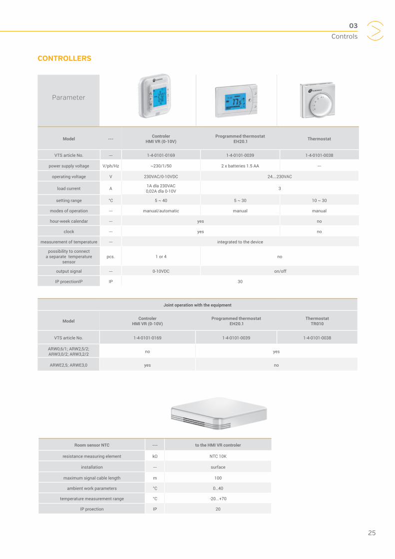
Model --- Controler HMI VR (0-10V)
Programmed thermostat EH20.1 Thermostat
VTS article No. --- 1-4-0101-0169 1-4-0101-0039 1-4-0101-0038
power supply voltage V/ph/Hz ~230/1/50 2 x batteries 1.5 AA ---
operating voltage V 230VAC/0-10VDC 24….230VAC
load current A 1A dla 230VAC 0,02A dla 0-10V 3
setting range °C 5 ~ 40 5 ~ 30 10 ~ 30
modes of operation --- manual/automatic manual manual
hour-week calendar --- yes no
clock --- yes no
measurement of temperature --- integrated to the device
possibility to connect a separate temperature
sensorpcs. 1 or 4 no
output signal --- 0-10VDC on/off
IP proectionIP IP 30
Joint operation with the equipment
Model Controler HMI VR (0-10V)
Programmed thermostat EH20.1
Thermostat TR010
VTS article No. 1-4-0101-0169 1-4-0101-0039 1-4-0101-0038
ARW0,6/1; ARW2,5/2; ARW3,0/2; ARW3,2/2 no yes
ARWE2,5; ARWE3,0 yes no
CONTROLLERS
Parameter
Room sensor NTC --- to the HMI VR controler
resistance measuring element kΩ NTC 10K
installation --- surface
maximum signal cable length m 100
ambient work parameters °C 0…40
temperature measurement range °C -20...+70
IP proection IP 20
03
Controls
25


04
KNOWLEDGE

1. HOW SHOULD THE DIAMETERS OF THE MAIN SUPPLY PIPELINE BE SPACED IN CASE MORE HEATERS ARE CONNECTED?
The diameter of the main pipe should be selected in such a way that the water flow rate does not exceed 2.5 m/s. This is caused by the need for a compromise between the investment costs associated with the size of the used tubes and operating costs, associated the water flow resistance in pipelines. We recommend the minimum diameters of the pipeline depending on the amount and type of heater devices connected to the bus line indicated in the following tables:
FAQ DEVICES
28
04
KNOWLEDGE
Number heaters VOLCANO VR1*
Maximum flow[m³/h]
Pipeline diameter[’’]
1 1,5 ¾
2 3 ¾
3 4,5 1
4 6 1 ¼
5 7,5 1 ¼
6 9 1 ¼
7 10,5 1 ¼
8 12 1 ¼
9 13,5 2
10 15 2
*Heaters connected in series to one bus.
Number heaters VOLCANO VR2*
Maximum flow[m³/h]
Pipeline diameter[’’]
1 2,5 ¾
2 5 1
3 7,5 1 ¼
4 10 1 ½
5 12,5 1 ½
6 15 2
7 17,5 2
8 20 2
9 22,5 2 ½
10 25 2 ½
*Heaters connected in series to one bus.
Number heaters VOLCANO V25*
Maximum flow[m³/h]
Pipeline diameter[’’]
1 1,1 ¾
2 2,3 ¾
3 3,4 1
4 4,5 1
5 5,7 1 ¼
6 6,8 1 ¼
7 7,9 1 ¼
8 9,0 1 ¼
9 10,2 1 ½
10 11,3 1 ½
*Heaters connected in series to one bus.
Number heaters VOLCANO V45*
Maximum flow[m³/h]
Pipeline diameter[’’]
1 2,0 ¾
2 4,0 1
3 6,0 1 ¼
4 8,0 1 ¼
5 10,0 1 ½
6 11,9 1 ½
7 13,9 2
8 15,9 2
9 17,9 2
10 19,9 2
*Heaters connected in series to one bus.
Number heatersVOLCANO V20*
Maximum flow[m³/h]
Pipeline diameter[’’]
1 0,9 ½
2 1,8 ¾
3 2,7 ¾
4 3,6 1
5 4,5 1
6 5,4 1 ¼
7 6,3 1 ¼
8 7,2 1 ¼
9 8,1 1 ¼
10 9,0 1 ½
*Heaters connected in series to one bus.

2. HOW CAN I CONNECT THERMOSTAT TO THE VENTILATOR, SO THAT THE VENTILATOR SHUT DOWN TOGETHER WITH THE VALVE SHUTDOWN?
The wiring diagrams contained in the technical documentation for VOLCANO unit heaters are included all possible configurations of electrical connections for the selected operating mode. If you are connecting only one heater, the thermostat can be connected in series with the phase wire behind the main switch / fuse installation. In this case, pay attention to the maximum thermostat contact load; load capacity should be at least 10 (3) A per one VOLCANO device. In the case of too little load on the thermostat connectors or more heaters are controlled by the thermostat, use electrical relay with the coil powered by the thermostat (230 V AC), working contact voltage will be 230 V AC, and working contact load will be adjusted to the amount of controlled VOLCANO devices.
3. CAN I CONNECT THE SUPPLY PIPE TO THE UPPER COLLECTOR OF WATER HEATER?
Yes, you can, you should just remember to provide adequate space for mounting the valve actuator, which we recommend you to install on the return nozzle. Furthermore, a heat exchanger fed by the top collector will operate less efficiently due to the increased flow resistance of the heating medium.
4. CAN VOLCANO VR1 / VR2 / V20 / V25 / V45I HEATERS BE SUPPLIED WITH ANTI-FREEZE AGENT?
Yes, you can, the most widely used antifreeze is a solution of water and glycol. However, please note that the fittings on the device may have limited resistance to glycol and make sure exactly what guidance on this topic are provided by the manufacturer of valves, circulating pumps, etc. The concentration of glycol can be up to 50%.
5. CAN VOLCANO VR1 / VR2 / MINI ALSO COOL THE AIR?
Theoretically, the effect of VOLCANO device’s work depends, inter alia, the medium flowing within the heat exchanger If the device is fed, for example, by a cold solution of water and glycol or ice-cold water, VOLCANO will start to work as the air cooler. Keep in mind, however, the phenomenon of condensation of water vapor on the heat exchanger as a result of lowering the temperature of the heat exchanger below the dew point of the air for given operating conditions. VOLCANO devices are not fitted with a drain, the user of the device needs to provide a drip tray or install a gutter under the device. Moreover, if you use theaters for cooling a phenomenon of dripping of the condensate water on the heat exchanger may occur. To prevent this, you should use the heater at a lower ventilator speed. The heaters are not suitable for cooling if they are installed under the roof. The condensed water dripping from the heat exchanger will drop to the floor.
6. CAN VOLCANO VR1 / VR2 / MINI HEATERS WORK TOGETHER WITH HEAT PUMPS?
VOLCANO water heaters can work together with heat pumps. However, heat pumps provide a low parameter of the heating medium, so it is suggested to apply VOLCANO VR2 heater to such installations and VOLCANO V20/V45 due to the higher nominal power and double-breasted exchanger in relation to the single-channel heater VOLCANO VR1 / V25.
29
04
KNOWLEDGE

1. WHAT ARE THE FUNCTIONS OF HMI VR CONTROL UNIT?
The most important function of the control unit is the automatic operation in the heating mode. The controller also has a function of cooling (in summer it helps to air the room). Automatic signal from the controller HMI VR is used for selecting the ventilator speed, in cooperation with ARWE3.0. regulator. The signal is in the range 0-10V which is resulted by temperature difference between the measuring and the target temperature.
2. SHOULD I CONNECT THE ADDITIONAL EXTERNAL DETECTOR TO HMI VR CONTROL UNIT TO MEASURE THE TEMPERATURE?
The controller has a built-in detector to measure the temperature of the NTC, so there is no need to connect an external sensor. If the driver is placed in another room, it is recommended that you connect it to an external NTC sensor specified in VTS EUROHEAT offer. When connected to a power supply controller automatically detects the sensor, it becomes the overriding element temperature measurement.
3. HOW CAN YOU TO ENTER THE MAIN DRIVER CONTROL PANEL OF HMI VR?
To start the control panel the control unit must be actuated. In this case it is necessary to set the operating mode to „OFF“ (off). In the control unit’s mode OFF (OFF) simultaneously press „M“ and „+“ buttons and hold for 5 seconds. This will open the programming mode driver which is described in the table (next page).
4. CAN I PROGRAM THE CALENDAR (AND WHICH ONE) IN HMI VR CONTROL UNIT?
The calendar is programmed in a five-day form, which means that the programmed first day (Monday) will be reproduced on consecutive working days (there is no possibility of individual settings for individual days). In the next
programming step settings for Saturday and Sunday are entered separately. In both cases it is possible to program up to two heating periods a day. The programming is carried out in terms of hourly schedule with respect to the time in which the function of heating or cooling is supposed to be activated (cooling is a function suggested only in summer). By pressing the „P“ you can switch the heating period to continuous mode (programmed heating periods will be deactivated but saved). Next pressing of „P“ will return to the previous setting of the heating time for 7 days.
5. WHICH POWER SUPPLY IS REQUIRED BY HMI VR CONTROL UNIT?
The control unit requires single-phase power: 1~230V +/-10%/50Hz.
FAQ Controls
control unit programming table
1. Temperature sensor calibration calibration +/-8°C
3. Heating, cooling, heating/cooling selection
4. Maximum temperature 5~50°C
5. Minimum temperature 5~50°C
6. Selection of displayed temperature ROOM (room) SET (set)
7. Manual increasing of the value of the output signal (+ 0V - return to default settings)
0, +1V, +2V, +3V, +4V
9. Saving of settings after the power supply shutdown
1: Yes0: No
10. Setting of a second temperature outside the programmed heating period (anti-freezing / economy)
2~22°C
11. The selection of operating for other temperature outside the heating period is set in p. 10 (anti-freezing / economy)
0 – no operation and anti-freeze protection
1 – anti-freeze protection, opening of the valve (2~22°C)
2 – operating in the economy mode (2~22°C), opening of the valve and operation of the ven-
tilator
12. Setting of clock minutes 0~59
13. Seting of hours 0~23
14. Selection of the weekday 1~7
15. RS485 address 1~233
16. Software version 100E
30
04
KNOWLEDGE

6. HOW CAN I ENTER THE CALENDAR PROGRAMMING MODE?
Hold „P“ button for 3 seconds in the standard display menu in the „ON“ mode (control unit switched on).
7. WITH HOW MANY DEVICES CAN HMI VR CONTROL UNIT COOPERATE?
The control unit can operate with maximum eight rotary speed controllers.
8. DOES THE CONTROL UNIT HAVE AN OPPORTUNITY FOR MANUAL WORK ALONGSIDE WITH AUTOMATIC?
Yes the control unit is equipped with „M“ button; using it you can select the operating mode. When selecting the manual mode of operating we specify one of three levels: 30%,60% or 100% of signal. Another switch by pressing „M“ button allows you to switch to automatic control.
9. DOES THE CONTROL UNIT HAVE A POSSIBILITY TO INCREASE OUTPUT SIGNAL DEPENDING ON ROOM VOLUME?
Yes, the control unit enables the modulation and adding value to the output signal for different (larger) rooms. This function is useful when the automatic signal cannot achieve the target temperature. This applies mainly to buildings with an area exceeding 150m2. It is recommended to increase the existing 0-10V output signal respectively for the following objects:
a) with the area of 150-250m²: +1V(+10%)
b) with the area of 250-400 m²: +2V(+20%)
c) with the area of 400-600 m²: +3V(+30%)
d) with the area of 600 m² and more: +4V(+40%)
e) the possibility to return to the standard settings + 0V
10. DOES THE CONTROL UNIT HAVE AN ANTI-FREEZE FUNCTION AND THE POSSIBILITY OF OPERATION IN ECONOMY MODE FOR ANOTHER TEMPERATURE?
Yes. HMI control unit has the ability to select another temperature, which can be used to work in economy mode or as antifreeze protection of the heat exchanger. Both of these functions are available outside the programmed heating period. The selection of the additional temperature range of 2 ~ 22°C takes place in the main control unit settings in p. 10. In the next point of operation configuration, i.e. 11, the operation mode selection takes place.
a) „0“ means that functions antifreeze protection and work in economy mode are disabled.
b) „1” will actuate antifreeze protection of the heater exchanger, open two-way valve when the room temperature drops below the set value in p. 10 (range 2~22°C)
c) “2” activates the work in economy mode outside the programmed heating period. This mode works the same way as a standard heating mode but for a different temperature (ventilator operation, flow opening) in the temperature range 2 ~ 22°C.
Both functions operate even when the controller is turned off or outside working hours set according in the calendar, provided the controller is connected to 230VAC power supply and operating mode „1” or „2” are selected in p. 11 of the main settings.
11. DOES THE CONTROL UNIT HAVE BMS FUNCTION?
Yes, the control unit has the function of BMS on RS485 interface and communication by MODBUS RTU protocol.
31
04
KNOWLEDGE

WWW.VTSGROUP.COM