cascopy - nasa€¦ · copy application of eva guidelines and design criteria volume iii - eva...
TRANSCRIPT
CASCOPY
APPLICATION OF EVA
GUIDELINES AND DESIGN CRITERIA
VOLUME III -
EVA SYSTEMS COST MODEL FORMATTING
FINAL REPORT
APRIL 1973
URS/MATRIX COMPANY
LIFE and ENVIRONMENTAL SCIENCES DIVISION
SUITE 101. 1275 SPACE MRK OSIVt. HOUSTON TEXAS 77rM
https://ntrs.nasa.gov/search.jsp?R=19730014356 2020-06-03T02:06:20+00:00Z

APPLICATION OF EVA
GUIDELINES AND DESIGN CRITERIA
FINAL REPORT
CONTRACT NAS9-12997
VOLUME III - EVA SYSTEMS COST MODEL FORMATTING
PREPARED FOR:
NATIONAL AERONAUTICS AND SPACE ADMINISTRATION
LYNDON B. JOHNSON SPACE CENTER
HOUSTON, TEXAS 77058
PREPARED BY:
NELSON E. BROWN
URS/SYSTEMS CORPORATIONURS/MATRIX COMPANY
LIFE AND ENVIRONMENTAL SCIENCES DIVISION
1275 SPACE PARK DRIVE
HOUSTON, TEXAS 77058
APRIL 1973
ESI mnrrix
FOREWORD
This study contract (NAS9-12997) was awarded by NASA Johnson Space Center(JSC) to (1) provide information and data concerning orbital ExtravehicularActivities (EVAs) in a format most useful to mission planners and experimentdesigners of future experiments, (2) develop conceptual design(s) of versatileEVA workstations for future space application, and (3) initiate development ofa model for estimating the impact of EVA costs on future payloads.
The contract report is presented in three volumes as follows:
Volume I: EVA Selection/Systems Design Guidelinesand Considerations
Volume II: EVA Workstation Conceptual Design
III:'
The report herein is a summary of the technical effort, an overview ofthe activities performed during the contract effort, and a presentation ofthe study results pertaining to the EVA Systems Cost Model --Volume III.
mnrnx
PREFACE
The United States' manned spaceflight programs prior to Skylab havequalified EVA as an operational technique for performing orbital and deepspace mission functions outside the spacecraft. The Skylab program willcapitalize on the established EVA techniques and equipment to retrieve solarastronomy experiment data contained in film magazines from the Skylab ApolloTelescope Mount (ATM). The Space Shuttle vehicle, which will begin orbitaltests in the late 1970's, will afford the opportunity to perform a varietyof tasks outside the spacecraft—perhaps more economically than any othermethod. Further, it is anticipated that spaceflights beyond the Space Shuttleand Modular Space Station will utilize manned EVA to great extents, and thateach future mission will provide for backup and contingency operations toenhance mission success, including mandatory provisions for crewman safety andrescue.
Since the EVA capability currently appears to be a requirement for manyfuture manned spaceflights, it is desirable to provide the mission planner andvehicle, experiment, and payload designers with information and data concerningthe selection of man for extravehicular (EV) functions. This study providesan overview of the factors that must be considered when utilizing man as anEV method, defines the impact that man and EV equipment have on the mission,vehicle, and payload, and provides conceptual EV workstation designs for per-forming the EV functions. The study also initiates development of an EVAsystems model to allow payload and experiment designers to assess the impactof EVA in terms of costs to future payloads.
In Volume I, parameters that require consideration by the planners anddesigners when planning for man to perform functions outside the vehicle arepresented in terms of the impact the extravehicular crewmen and major EV equip-ment items have on the mission, vehicle, and payload. Summary data on man'sperformance capabilities in the weightless space environment are also provided.
11
mmnxThe performance data are based on orbital and transearth EVA from previousspaceflight programs and earthbound simulations, such as water immersion and"zero-g" aircraft.
Several EV workstation concepts were developed and are documented inVolume II of this report. The workstation concepts were developed followinga comprehensive analysis of potential EV missions, functions, and tasks asinterpreted from NASA and contractor Space Shuttle and Space Station studies,mission models, and related reports. The design of a versatile, yet portable,EVA workstation is aimed at reducing the design and development costs for eachmission and aiding in the development of on-orbit serviceable payloads. Thereplacement of dedicated EVA workstations with portable modular units, whichcan be readily adapted to numerous worksites, represents a sizeable cost savingsto payloads using EVA.
The development of a model for estimating the impact of manned EVA costson future payloads was initiated during the study. Basic information on theEV crewman requirements, equipment, physical and operational characteristics,and vehicle interfaces is provided. The cost model is being designed toallow system designers to quantify the impact of EVA on vehicle and payloadsystems. The results of this effort are contained in this volume of thereport—Volume III.
iii
FTP] mnirn
ACKNOWLEDGEMENTS
The NASA Technical Monitor for this study was Mr. David C. Schultz, Chief,EVA and Experiments Branch (CG3), Crew Procedures Division, Flight Crew Opera-tions, Johnson Space Center, Houston, Texas. Technical direction for the studywas provided by Mr. Schultz; valuable assistance in obtaining information anddata was supplied by personnel within the EVA and Experiments Branch. Appre-ciation is expressed to Dr. Stanley Deutsch, Director, Bioengineering Division,Office of Life Sciences, NASA Headquarters, for his worthy suggestions andassistance in arranging for the conduct of the study.
The contractor Principal Investigator for the study was Mr. Nelson E.Brown, Division Director, Life and Environmental Sciences Division, URS/MatrixCompany, URS Systems Corporation. Principal contributors within the URS/MatrixCompany were Dennis C. DeWitt and G. Lloyd Phil pot.
IV

TABLE OF CONTENTS
SECTION PAGE
FOREWORD i
PREFACE iiACKNOWLEDGEMENTS iv
LIST OF TABLES vi
LIST OF FIGURES vii
ACRONYMS AND ABBREVIATIONS viii
DEFINITION OF TERMS x
1.0 PURPOSE OF THE MODEL 1
2.0 BACKGROUND 3
3.0 OVERALL METHODOLOGY .5
4.0 MAN'S CAPABILITIES IN EVA 7
5.0 EVA COST MODEL FORMATTING 15
5.1 Space Suits and Support Equipment 175.2 Stowage Support Equipment . 225.3 Maintenance, Don/Doff and Drying Support Items 255.4 Life Support Systems 285.5 Crewman Translation and Package Transportation Aids ... 345.6 Worksite Force Requirements vs. Restraints 375.7 Pre-EVA Crew Time 405.8 Post-EVA Crew Time .435.9 Consumables and Expendables 465.10 Special Tools ..... 495.11 EVA Crewman Operational Envelope 545.12 EVA Supporting Equipment 565.13 EVA Costs Summary 58
REFERENCES 62
rramHTrix
LIST OF TABLES
TABLE PAGE
5-1 SPACE SUITS AND SUPPORT EQUIPMENT . 20
5-2 STOWAGE SUPPORT EQUIPMENT 24
5-3 MAINTENANCE, DON/DOFF AND DRYING SUPPORT ITEMS . 27
5-4 LIFE SUPPORT SYSTEMS 31
5-5 CREWMAN TRANSLATION AND PACKAGE TRANSPORTATION AIDS 36
5-6 WORKSITE FORCE REQUIREMENTS VS. RESTRAINTS . . 39
5-7 PRE-EVA CREW TIME 42
5-8 POST-EVA CREW TIME 45
5-9 CONSUMABLES AND EXPENDABLES 48
5-10 SPECIAL TOOLS 505-11 EVA CREWMAN OPERATIONAL ENVELOPE .... 55
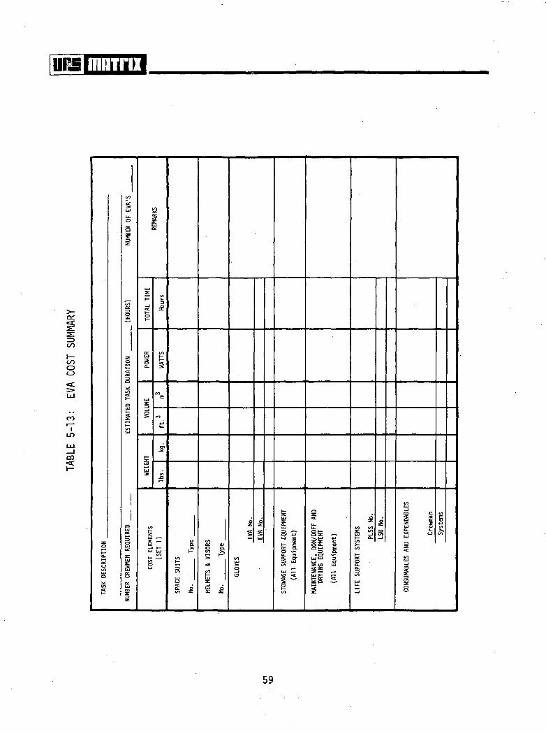
5-12 EVA SUPPORTING EQUIPMENT 575-13 EVA COSTS SUMMARY 59
vi
LIST OF FIGURES
FIGURE
3-1 COST MODEL FLOW SEQUENCE
PAGE
6
vn

mnirB
ACRONYMS AND ABBREVIATIONS
AES Advanced Extravehicular SuitA/L AirlockALSS Advanced Life Support SystemAMU Astronaut Maneuvering UnitATM Apollo Telescope MountCCA Communications Carrier AssemblyCCU Crew Communications UmbilicalCSM Command Service ModuleCWG Constant Wear GarmentECS Environmental Control SystemEMU Extravehicular Mobility UnitESC External Sequence CameraEV ExtravehicularEVA Extravehicular ActivityEVCS Extravehicular Communications SystemFCMU Foot Controlled Maneuvering UnitFTB Film Transfer BoomGATV Gemini-Agena Target VehicleHHMU Handheld Maneuvering UnitIVA Intravehicular ActivityJSC Lyndon B. Johnson Space CenterLCG Liquid Cooling GarmentLSS Life Support SystemLSU Life Support UmbilicalMDA Multiple Docking AdapterMEED Microbial Environment Exposure DeviceMWP Maneuvering Work PlatformNASA National Aeronautics and Space AdministrationOBS Operational Bioinstrumentation SystemOPS Oxygen Purge System
ym
mnrnx
ACRONYMS AND ABBREVIATIONS'(Cont'd.)
PGA Pressure Garment AssemblyPLSS Portable Life Support SystemPSI Pounds per Square InchSIM Scientific Instrument ModuleSLSS Secondary Life Support SystemUCTA Urine Collection Transfer AssemblyUMB UmbilicalWIS Water Immersion Simulation
IX

mninx
DEFINITION OF TERMS
Many of the terms used in the report have various connotations within theNASA and aerospace community. Some are readily familiar only to personnelinvolved directly in the EVA field. Therefore, as an aid to the reader,several of the perhaps unfamiliar EVA terms are defined below.
PRESSURE GARMENTASSEMBLY (PGA)
EXTRAVEHICULARMOBILITY UNIT(EMU)
ADVANCED EXTRA-VEHICULAR SUIT(AES)
LIQUID COOLINGGARMENT (LCG)
CONSTANT WEARGARMENT (CWG)
LIFE SUPPORTSYSTEM (LSS)
A PGA consists of the following items which constitute thebasic space suit:• Torso-limb suit • Helmet§ Gloves • Boots• Controls and Displays • Neck Dam• Electrical and Bio-
instrumentation Harness
An EMU consists of the following items which make up acomplete extravehicular support system:
Pressure Garment Assembly (PGA)Liquid Cooling Garment (LCG)Life Support System (LSS)Secondary Life Support System (SLSS)Constant Wear Garment (CWG)Extravehicular Visor AssemblyUrine Collection Transfer Assembly (UCTA)Fecal Containment Subsystem (FCS)Communications Carrier Assembly (CCA)
Any space suit in the development stage with "improvements"over existing suits.
A garment worn in direct contact with the skin whichincorporates liquid coolant tubes to accomplish theprimary body cooling requirements.
A one-piece, short-sleeved garment covering the crewman'storso and feet, leaving the neck, head and lower armexposed. May be worn EVA in place of LCG but depends onworkload, time, etc.
A primary system, either portable or umbilical, whichsupplies the required breathing medium and pressure toprovide a viable atmosphere for the suited EVA crewman.
x

SECONDARY LIFESUPPORT SYSTEM(SLSS)
EXTRAVEHICULARVISOR ASSEMBLY
URINE COLLECTIONTRANSFER ASSEMBLY(UCTA)
FECAL CONTAINMENTSUBSYSTEM (FCS)
COMMUNICATIONSCARRIER ASSEMBLY(CCA)
OPERATIONAL BIO-INSTRUMENTATIONSYSTEM (OBS)
PORTABLE LIFESUPPORT SYSTEM(PLSS)
OXYGEN PURGESYSTEM
WATER IMMERSIONSIMULATION (WIS)
FILM TRANSFERBOOM (FTB)
A backup system serving the same functions as the LSS.Usually a self-contained unit with less capacity than theprimary LSS.
A visor attached to the helmet to provide visual, thermal,impact, and micrometeoroid protection during EVA.
A flexible bag type device worn inside the space suit usedto temporarily store urine while wearing the PGA.
The FCS consists of a "diaper" type garment which acts asa comfort pad while wearing the PGA.
The CCA consists of a head fitted assembly incorporatingredundant microphones and earphones which provide the EMUsystem communications requirements.
The OBS is a rectangular section of woven Teflon clothcontaining pockets and restraining features which housesignal conditioners, dc-dc converters, and crewmanidentification modules used in the EVA transmission ofcritical body functions.
A completely self-contained life support system usuallycarried on the back of the EVA crewman. The units normallycontain communications, telemetry, and secondary lifesupport capabilities.
A unit functioning in the same capacity as a Secondary LifeSupport System. Usually associated with a PLSS.
Refers to EVA simulations/hardware evaluations when thesuited crewman is totally submerged and made neutrallybuoyant.
Electrically and manually actuated extendible boom used totransfer film modules a distance of approximately 30 feet(9.1 m) on Skylab. Also used in aerospace antennaapplications.

mninx
A MODEL FOR ESTIMATING THE COST OF EVA/IVA
SECTION 1.0.' . 'PURPOSE OF THE MODEL
Extravehicular activity (EVA) and intravehicular activity (IVA) have beenproposed as methods of accomplishing numerous tasks on future spacecraft.Experimenters, mission planners, and spacecraft designers are interested in themost economical means of servicing experiment payloads, deploying satellites,and collecting experiment data. The spacecraft designers and mission plannersare also concerned with spacecraft external inspection, performing minormaintenance activities and emergency safety/rescue operations. The model pro-posed and partially formatted in this report, when complete, will provide ameans of estimating the cost of placing a crewman outside the vehicle to per-form the desired tasks.
In order to effectively propose the use of EVA/IVA, the potential usermust have information on the considerations which go into specifying EVAcapability. Volume I of this final report presents a qualitative descriptionof the many factors which are impacted by the specification of EVA. TheEVA Cost Model is intended to present a quantitative indication of the costs
of including EVA/IVA capability to perform certain tasks.
The EVA Cost Model is designed for the experimenter or mission planner
who is not working directly in the EVA field. The model does not require thatexperiment or payload equipment be designed before it is employed. In fact,it is preferred that the model be exercised in the early design stages sincethe costs and provisions for EVA or alternative techniques are likely to affectdesigns. The model will not define all costs or quantify exact costs of pro-viding EVA but is intended as a planning device to aid in the comparison ofEVA with other techniques. It should be noted that this report does not attemptto provide a completed EVA Cost Model; but a methodology and format for laterdevelopment.
\\m mamThe terms "mission planners" and "experiment/payload designers" are used
frequently throughout the report. The contractor's use of these terms haveno implications toward identifying or indicating the NASA center, organization,or personnel that may be responsible for vehicle, experiment, or payload design/selection. The terms only refer to the assemblage of Government, industrial,institutional, or foreign organizations involved in developing a payload/vehicle to be included in the Space Shuttle Program with no indication towardspecifying a governing organization. Since the NASA-JSC is responsible fordeveloping the complement of EVA supporting systems for the Space Shuttle, theexperiment and payload planners and designers will be required to design theirhardware around those EVA systems. The payload planning and designing teamswill be involved in specifying the quantity of each EVA support componentbased on the specific requirements of their experiments.
SECTION £.8 : * - Meantime*
The EVA Cost Model has evolved from an increasing desire on the part ofNASA to assist spacecraft users in identifying an economical means of servicingfuture payloads. The Model also serves to reduce the dollar cost to the userin selecting EVA systems for the servicing operations. At present, the basicargument used to justify EVA as an operational technique is that the capability
already exists; why not use it? The Space Shuttle will afford EVA capabilityfor the crewmen according to current study directives. However, the fact thatan EVA capability exists does not imply that EVA is the most cost effectivemethod to perform on-orbit tasks; trade studies must be made.
In mid-1972 the URS/Matrix Company completed an Extravehicular Activities(EVA) Guidelines and Design Criteria document. This report marked the comple-tion of an effort to collect and synthesize information that is currently knownabout EVA and IVA. The EVA Guidelines and Design Criteria document containsmajor sections on the history of EVA, the capabilities of EVA hardware, EVAsplanned for future missions, human performance capabilities in orbit, and EVA
crewman physiology. If studied from cover to cover, one could be brought upto date on many of the general aspects in the EVA field.
A logical step beyond the Guidelines document was the expansion of selectedareas of the report for more thorough coverage. This is being accomplished inVolume I of the study effort reported here. Another logical step beyond theoriginal document was the preparation of an EVA cost model. The model couldbe constructed on the basis of what is currently known about EVA and EVAsystems, and could be structured for use by individuals not directly involvedin EVA design.
As initially concerned, the cost model would allow an experimenter ormission planner to roughly estimate the costs of utilizing EVA to accomplisha selected task. The major costs which are relevant to this type of decision
mninxare weight, volume, and crew time—all of which are charged against the pay-load which requires them. Such "charges" are not unique to EVA but are assessedto the payload independent of the system/technique used in servicing the payload.Weight and volume penalties, of course, reduce the weight and volume of thepayload scientific equipment that can be carried on an individual flight shouldthat flight be weight critical. Similarly, EVA crew time reduces the amountof on-orbit time available to conduct experiments and reduce data as would thecrew time used in the preparation, checkout, and operation of systems such asteleoperators and remote manipulators.
Estimates of EVA costs may be affected by developments in the EVA hardwarefield. For example, the development of an 8.0 psi space suit for use on a14.7 psi spacecraft (i.e., cabin pressure) would eliminate pre-breathing timefrom the pre-EVA time allotment (ref. 3.1). Improved designs of the suitjoints and access provisions may also reduce donning and doffing times fromthe pre- and post-EVA periods, respectively. The increased mobility of theproposed suits could further decrease pre- and post-EVA times by altering theworksite ingress/egress times. Improvements in portable life support systemsmay change the configuration of these systems (such as ice packs instead ofsublimators). However, these improvements are not expected to have a majoreffect on the weight, volume, and time required for systems checkout, donning,doffing, servicing, etc.
m=\ mniru
The basic procedure to be used in exercising the EVA Cost Model involvesthree preliminary steps:
(1) Prepare a description of the task(s) to be performed in EVA--Thisdescription may include statements such as: retrieve 30 Ib. (13.6 kg)film magazine and return it 50 feet (15.2 m) to the Shuttle Orbiterairlock; adjust antenna pointing with special tool; inspect andmonitor payload operations; etc.
(2) Review of EVA capabilities data—Demonstrated on-orbit and simulatedEVA capabilities are described in Section 4.0 to enable the user toestimate the duration and number of crewmen required to perform thetask(s).
(3) Estimate EVA requirements—After reviewing the EVA capabilities data,the user will prepare an estimate of the number of EVA crewmen requiredfor the task, the duration of each EVA, and the number of EVAs required.
With the three basic preparatory steps completed, the user enters thecost charts of the model. The overall flow of this sequence is depicted inthe diagram in Figure 3-1.
The Cost Model is arranged as a series of charts and tables presentingeach dependent variable (e.g., suit weight, life support system volume, work-station power, LiOH cannister weight) as a function of the independentvariables (e.g., number of crewmen EVA, EVA duration) quantified earlier. Taskdescription is included as an input to the Cost Model in the flow diagram toallow package sizes, masses, translation distances, etc. to be included inthe model.

mninx
PREPAREEVA TASKDESCRIPTION
REVIEW BASICEVACAPABILITIES
ESTIMATEEVAREQUIREMENT
No. CrewmenDuration
No. EVAs
TCI s If
EVACOSTMODEL
Irew TimeExpendables „
Etc.
FIGURE 3-1: COST MODEL FLOW SEQUENCE
Descriptions of the way to use each Cost Model Chart are included withthe charts in subsequent sections of this report.
SECTION 4.0 ' " ^ ' HATS CAMSILITIES- !& M *
In order to estimate the number of crewmen required for EVA, the EVA dura-tion, and the number of EVAs required for a particular task, the following dataare provided. The data are presented in two major sections: Flight Resultsand Simulation Results. Although Flight Results are more accurate in manycases, the variety of tasks which have been performed and quantified is limited.Also, many of the inflight tasks were performed in conjunction with the evalua-tion of EVA crewman restraint and stabilization equipment/techniques which weresignificantly improved for later missions and may not be totally representativeof current capabilities and time requirements. Flight and simulated capabilitiesare arranged by the major task activities required in EVA which include thefollowing:
A. FLIGHT RESULTS
• Hatch Ingress/Egressa Workstation Ingress/Egress• Worksite Activities
- Gemini- Using foot restraints (Gemini)- Apollo
• Various EVA Activities
B. SIMULATION RESULTS
• Cargo Transportation• Payload Deployment• Crewman Translationt Worksite Activities
mnrizThe times shown for performing the various tasks were derived from an
assessment of the following: (1) final flight timelines developed throughwater immersion simulation for the Gemini and Apollo Orbital EVAs, (2) corre-lation studies of the Gemini EVA simulations with flight results, and (3)flight plans developed for Skylab EVA. The crew times found in each of theabove sources for comparable tasks varied somewhat and were considered to bedependent upon the restraint system used, EVA hardware configuration variations,and other concurrent subtasks. Therefore, the times given for performing thetasks listed in this report are "best estimates" to the nearest minute. Thesetimes can be used only as an initial indication for tasks on future EVA missions.Knowledge of each task, the supporting hardware involved (restraints, work-stations, mobility aids), and the crewman support systems (pressure suit, lifesupport system) is required as an initial input to time estimation. Best-timeestimates are obtained only from end-to-end task simulations using state-of-the-art simulation facilities and techniques.
A. FLIGHT RESULTS
• Hatch Ingress/Egress
(a) Assuming a hatch no less than 30 inches (.76 m) in diameterwith mobility aids (ref. 3.2):
* Less than 2 minutes to egress or ingress without cargo
* Less than 4 minutes to egress or ingress with cargo beingtransferred to a crewman inside the hatch. (Cargo amountequal to or less than what can safely be carried by a singlecrewman in transportation.)
• Workstation Ingress/Egress
(a) Assuming handholds are provided for ingress/egress of Apollo"Dutch Shoes" or Skylab foot restraints (ref. 3.2):
8
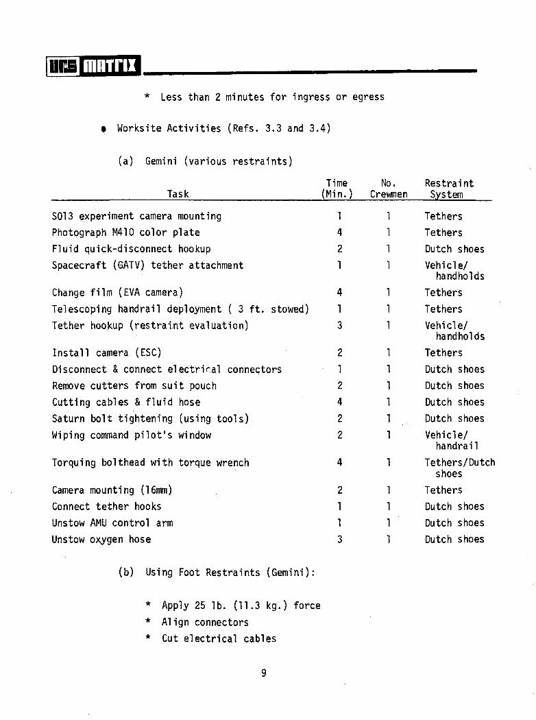
* Less than 2 minutes for ingress
• Worksite Activities (Refs. 3.3 and 3.4)
(a) Gemini (various restraints)
or
TimeTask (Min.
SOI 3 experiment camera mountingPhotograph M410 color plateFluid quick-disconnect hookupSpacecraft (GATV) tether attachment
Change film (EVA camera)Telescoping handrail deployment ( 3 ft. stowed)Tether hookup (restraint evaluation)
Install camera (ESC)Disconnect & connect electrical connectorsRemove cutters from suit pouchCutting cables & fluid hoseSaturn bolt tightening (using tools)Wiping command pilot's window
Torquing bolthead with torque wrench
Camera mounting (16mm)Connect tether hooksUnstow AMU control armUnstow oxygen hose
1421
41
3
2
1
24
2
2
4
2
11
3
egress
No.) Crewmen
1111
111
111111
1
1111
RestraintSystem
TethersTethersDutch shoesVehicle/
handholdsTethersTethersVehicle/
handholdsTethersDutch shoesDutch shoesDutch shoesDutch shoesVehicle/
handrailTethers/Dutch
shoesTethersDutch shoesDutch shoesDutch shoes
(b) Using Foot Restraints (Gemini):
* Apply 25 Ib. (11.3 kg.) force* Align connectors* Cut electrical cables

mirm* Apply torque of 200 in. Ibs. (2.3 kgm.) with 9 in. (22.9
cm.) wrench* Apply 100 in. Ibs. (1.2 kgm.) torque with 5 in. (12.7 cm.)
wrench(NOTE: Force limits have not been defined for EVA crewmenin weightlessness but with proper restraints shouldapproach those of the crewman on earth under shirtsleeveconditions.)
(c) Apollo (Ref. 3.5)
* Retrieve 85 Ib. (38.6 kg.) panoramic camera - 19.3 in. dia.x 6.2 in. (.49 m x .16 m)
- Translate to Scientific Instrument Module (SIM) bay -approx. 10 ft. (3.05 m) using single handrails andhandholds
- Retrieve camera
- Transport camera from SIM bay to Command ServiceModule (CSM) hatch - approx. 10 ft. (3.05 m)
* Retrieve 27 Ib. (12.2 kg.) mapping camera cassette - 10.5in. dia. x 8.5 in. (26.7 cm. x 21.6 cm.)
- Translate to SIM bay - approx. 10 ft. (3.05 m) usinghandrails and handholds
- Retrieve cassette
- Transport cassette from SIM bay to CSM hatch - approx.10 ft. (3.05 m)
* Inspect equipment at SIM bay(NOTE: Three round trips were made to the SIM bay onApollo 15 during a 38-minute EVA period. [Retrieval taskscould have been accomplished in less time if desired.])
t Various EVA Activities
- Hand Held Maneuvering Unit (HHMU) evaluation- Umbilical evaluation (tether dynamics)
10
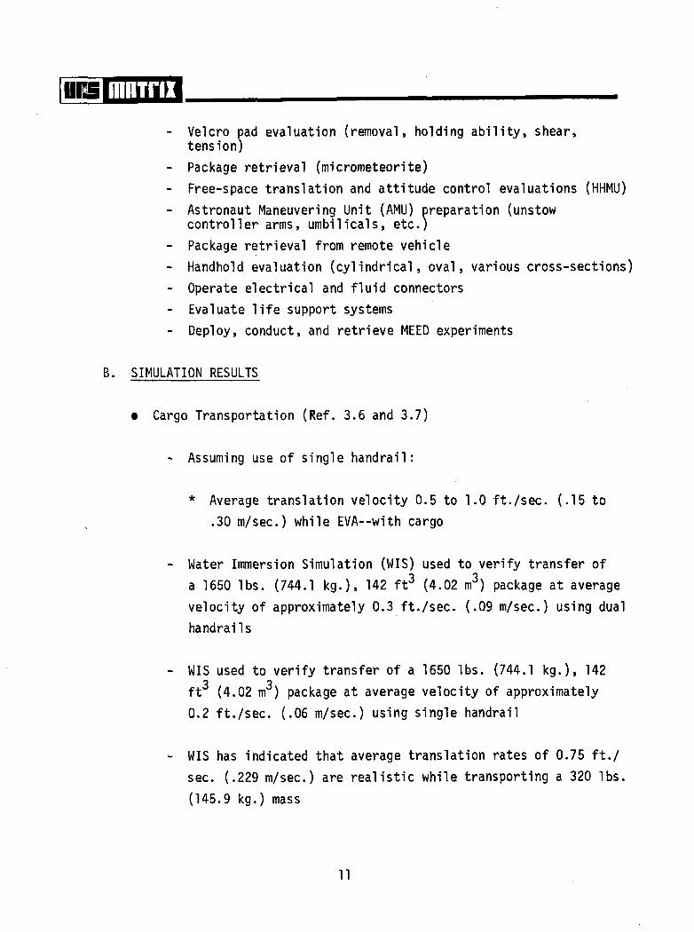
Eld mm™- Velcro pad evaluation (removal, holding ability, shear,
tension)- Package retrieval (micrometeorite)- Free-space translation and attitude control evaluations (HHMU)- Astronaut Maneuvering Unit (AMU) preparation (unstow
controller arms, umbilicals, etc.)- Package retrieval from remote vehicle- Handhold evaluation (cylindrical, oval, various cross-sections)- Operate electrical and fluid connectors- Evaluate life support systems- Deploy, conduct, and retrieve MEED experiments
B. SIMULATION RESULTS
• Cargo Transportation (Ref. 3.6 and 3.7)
- Assuming use of single handrail:
* Average translation velocity 0.5 to 1.0 ft. /sec. (.15 to.30 m/sec.) while EVA--with cargo
- Water Immersion Simulation (WIS) used to verify transfer ofa 1650 Ibs. (744.1 kg.), 142 ft3 (4.02 m3) package at averagevelocity of approximately 0.3 ft. /sec. (.09 m/sec.) using dualhandrails
WIS used to verify transfer of a 1650 Ibs. (744.1 kg.), 1423 ?ft (4.02 m ) package at average velocity of approximately
0.2 ft. /sec. (.06 m/sec.) using single handrail
WIS has indicated that average translation rates of 0.75 ft./sec. (.229 m/sec.) are realistic while transporting a 320 Ibs.(145.9 kg.) mass
11
mnirii• Payload Deployment (Ref. 3.8)
- WIS used to verify 2-man deployment of simulated payloadweighing 8,500 Ibs. (3855.6 kg.). Dimensions wereapproximately 19 ft. (5.8 m) by 3.5 ft. dia. (1.07 m dia.),Additional payload deployment/handling simulations arescheduled to be conducted in the NASA Marshall SpaceFlight Center water immersion facility. No limit hasbeen set on the size and mass of the largest payloads tobe handled. Up to 65,000 Ibs. (29,484 kg.) is being con-sidered.
• Crewman Translation (Ref. 3.9)
- Assuming use of single handrai.l:
* WIS used to establish 1.0 to 2.0 ft./sec. (.3 to .6m/sec.) IVA translation velocities
* Average translation velocity 1.0 ft./sec. (.3 m/sec.)while EVA
• Worksite Activities (Ref. 3.10)
- WIS has indicated that crewmen can apply approximately.60 Ib. (27.2 kg.) force in a forward direction on anobject 28 to 52 inches (.7 to 1.3 m) above the floorwhere foot restraints (Skylab) are provided.
- WIS has indicated that crewmen can apply in excess of60 Ib. force (27.2 kg.) in an isometric (force reacting)horizontal pulling fashion to a lever approximately1 ft. (.3m) above the floor where foot restraints(Skylab IVA) are provided.
12

- WIS has indicated that horizontal pulling forces aregreater than horizontal pushing forces using footrestraints.
t Various EVA Simulations - Skylab (Ref. 3.9)
- Workstation ingress/egress (5 workstations)
- Package handling from airlock—size up to approximately30 x 24 x 16 in. (.8 x .6 x .4 m)
- Crewman translation via a combination of single and dualhandrails of approximately 30 ft. (9.1 m)
- Deployment and actuation of package transfer systems--Film Transfer Boom (FTB) and clothesline
- Umbilical management
- Film magazine access door actuation
- Visual alignment of Apollo Telescope Mount (ATM) Canister
- Deploy mechanical booms/arms
- Retrieval/replacement of film magazine and cassettes
- Actuation of electrically powered control devices
- Package handling from experiment to transfer devices
- Camera (16 mm) deployment, alignment, actuation andretrieval
13
The general capabilities cited in the above paragraphs do not constitutethe total spectrum of activities that the EVA crewman has successfully per-formed in simulation programs. The total EVA simulations conducted by NASAand industry are far too numerous to include in a single document. This EVAcapabilities section will, however, be expanded in the final EVA Cost Modelunder the "Man's Capabilities in EVA" section.
14
mniru
SECT10H 5,0 * ' ' EVA COST
The tables and charts which follow, when complete, will allow an estimateto be made of the costs of an existing EVA capability to perform a selectedtask on the Space Shuttle or future vehicle. By combining the task require-ments for a selected task(s) with the EVA capabilities information providedin the previous section, an estimate can be derived of the weight, volume,crew time, etc. required for EVA systems to support that task.
No costs are provided for automated or aided EVA systems. It is likelythat such systems could be competitive with EVA for many tasks. The remotelyoperated Shuttle manipulator arms/booms, for example, may be useful in handlingpayloads. Free-flying or restrained teleoperators may find application in theservicing of certain payloads. These systems will most likely require similar(or perhaps more) crew time, weight, and volume as the EVA operations when allimpacts are identified and supporting data are available.
This preliminary Cost Model development effort provides the requiredmethodology and formatting for building a complete model. In follow-oncontracts to this effort, the EVA Cost Model will be totally expanded into atool for use by vehicle designers and payload planners. The tables containedin this section will be completed, based primarily on Skylab EVA systems andEVA systems developed for the Space Shuttle Orbiter. Provisions for additionalentries into each cost chart will be included to reflect advanced EVA systemsresulting from JSC EVA/IVA support systems study and development contracts andinhouse programs.
The cost tables and charts are included for the major EVA areas listedbelow:
(5-1) SPACE SUITS AND SUPPORT EQUIPMENT
(5-2) STOWAGE SUPPORT EQUIPMENT (Space Suits)
15
ranTrii
(5-3) MAINTENANCE, DON/DOFF AND DRYING SUPPORT ITEMS
(5-4) LIFE SUPPORT SYSTEMS
(5-5) CREWMAN TRANSLATION AND PACKAGE TRANSPORTATION AIDS
(5-6) WORKSITE FORCE REQUIREMENTS VS. RESTRAINTS
(5-7) PRE-EVA CREW TIME
(5-8) POST-EVA CREW TIME
(5-9) CONSUMABLES AND EXPENDABLES
(5-10) SPECIAL TOOLS
(5-11) EVA CREWMAN OPERATIONAL ENVELOPE
(5-12) EVA SUPPORTING EQUIPMENT
16

5.1 SPACE SUITS AND SUPPORT EQUIPMENT
It is anticipated that an advanced pressure suit will be developed andapproved for the Space Shuttle program; the suit will provide improvedmobility, don/doff characteristics, minimum energy expenditure, etc. overcurrent models. This will essentially preclude an option to the payloadplanner or designer in selecting the major torso assembly for use duringEVA payload servicing. 'However, the ancillary equipment (e.g., helmets,visors, glove components, etc.) from the existing A7L-B suits may be usedwith the advanced suits.
Since each payload servicing operation will vary with respect to taskrequirements, performance time, workload, crewmen required, etc., the payloaduser will be involved in selecting the quantities of certain pressure suitancillary equipment. Each payload EVA servicing mission is considered from anend-to-end basis in selecting the quantity of gear necessary. Spare pressuresuits and hardware items are based on the number of EVA crewmen, totalpressurized time, and severity of use per mission. (Spares requirements forthe suits and support equipment aboard the Shuttle have not been established.)As a minimum, the following suit components are required by each EVA crewmanbased on one EVA mission:
• 1 Pressure Garment Assembly (includes boots)• 1 helmet• 1 extravehicular helmet visor assemblyt 1 pair EVA gloves• 1 bioinstrumentation system• 1 communications carrier assembly• 1 set constant wear garments or 1 liquid cooling garment• 1 personal radiation dosimetert 1 passive radiation dosimeter• 1 urine collection transfer system• 1 fecal containment system• 1 drinking bag assembly (optional)
17

rrra mnrnxThe experiment/payload planning team is responsible for determining the
total number of each EVA item required and the total weight and volume penaltyto his payload.
Table 5-1 is provided to allow an estimate to be made of the weight andvolume of space suits and supporting equipment. The items listed are thosecurrently required for Skylab EVA/IVA. The weight and volume values are basedupon the A7L-B suits for use with umbilical or portable life support systems.The table is designed to accommodate entries for advanced suits and equipment.
To use the table,
(1) Establish the number of crewmen that will be required in EVA toperform the selected task(s).
(2) Establish the number of EVAs required to perform the selected task(s).
(3) Identify the column which corresponds to the number of crewmen EVAestablished above.
(4) Obtain component weights and volumes by descending the appropriatecolumn to the row containing the item desired. The weight andvolume of the item under the use conditions established above aregiven in the cell at the intersection of the row and column.
(5) Establish the number of inflight spare components required.
(6) Adjust component weights and volumes by multiplying the values givenby the number of EVAs required according to the Spares and Remarkscolumns. This Remarks column contains an entry of "1 per crewmanper EVA" for items that must be replaced after each EVA. The weightsand volumes of these items must be multiplied by the number of EVAsestablished above. Record in "FOR USE BY PLANNER" column.
18

mninx(7) Total weight and volume of space suits and support equipment may be
obtained by adding down the "FOR USE BY PLANNER" columns afteradjustments for the number of EVAs and spares are made.
19

mnrnx
,6
tl.
cr
oQ.O_
V)
oB
C/)
OL.CO
ILO
UJ_lCO
v> uj
5«c is0.0-
CO OOOO«>
C »
•sa: to o
Q, flJ O V6 > >
"S -3^^O XCJC3<o> I t I3
o o-«-^ £ oo
aVI
O <U"O
IIIC Ul UJ
20

oo
'•%»if-i f £&»'
s«lam¥S
LoJ
a:oa.a.
o3
CO
O<a.
iLO
ti
3VI
I
21
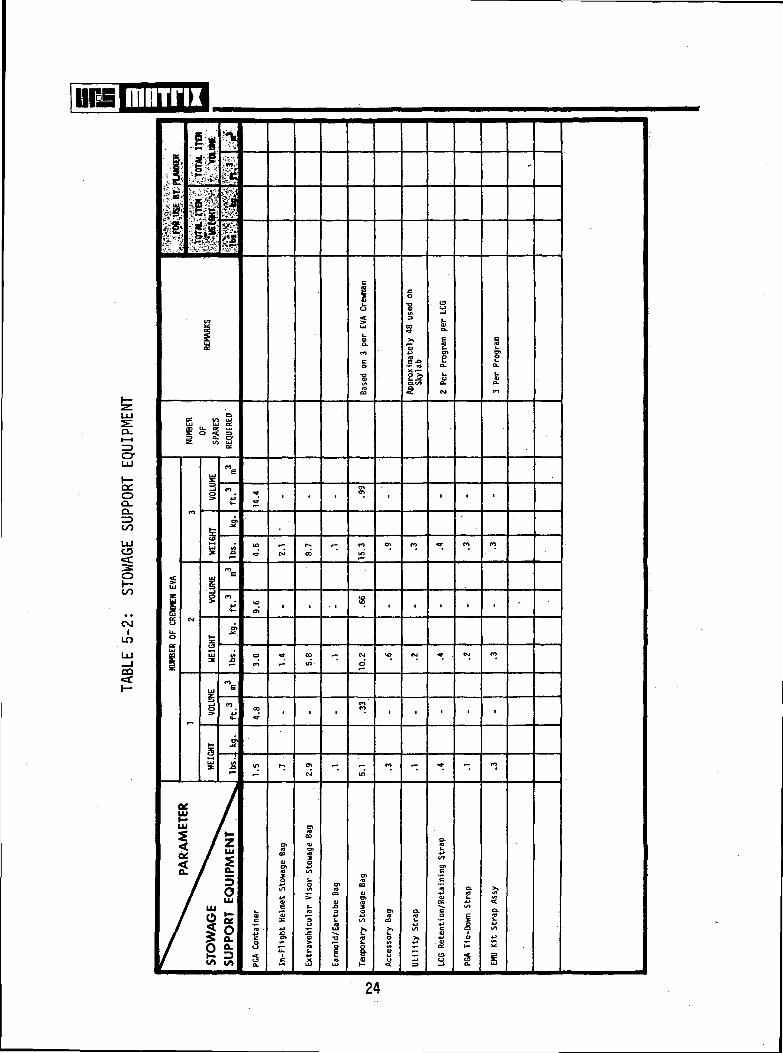
mninx5.2 STOWAGE SUPPORT EQUIPMENT
On previous space programs several pieces of supporting hardware associatedwith the pressure suits and EVA life support systems have required specialprotective or stowage devices (e.g., containers, bags, straps) when handledor stowed on-orbit. Depending on the stowage provisions available on theSpace Shuttle, an assortment of such protective items will be required forfuture EVAs. The protective items will vary in configuration with the EVAhardware specified for the Shuttle.
Table 5-2 provides data on several miscellaneous stowage support items.The items listed are generally small and lightweight but are necessary to pre-vent damage to the EVA equipment. The weights and volumes quoted in the tableare based on Apollo and Skylab hardware and are considered within the state-of-the-art for future missions.
To use the table,
(1) Establish the number of crewmen required to be EVA to accomplishthe selected task(s).
(2) Establish the number of EVAs required to accomplish the selectedtask(s).
(3) Identify the column which corresponds to the number of crewmen EVAestablished above.
(4) Obtain component weights and volumes by descending the appropriatecolumn to the row containing the component.
(5) Establish the number of spare components required.
(6) Adjust component weights and volumes by multiplying values givenby the number of EVAs according to notes in the Spares and Remarks
22
mnirixcolumns. Other adjustments may also be required on the basis ofnotes in the Remarks column. Record in "FOR USE BY PLANNER"columns.
(7) Obtain total weight and volume by scanning down the "PLANNER"column after adjustments are made.
23
mninx
CL.I—I
cr
oQ-d.^>CO
Ioo
OJI
LO
CO
"ftI" 1* \ .1
u. S 20 2 §.
5;Q.
IO»
E
I
24
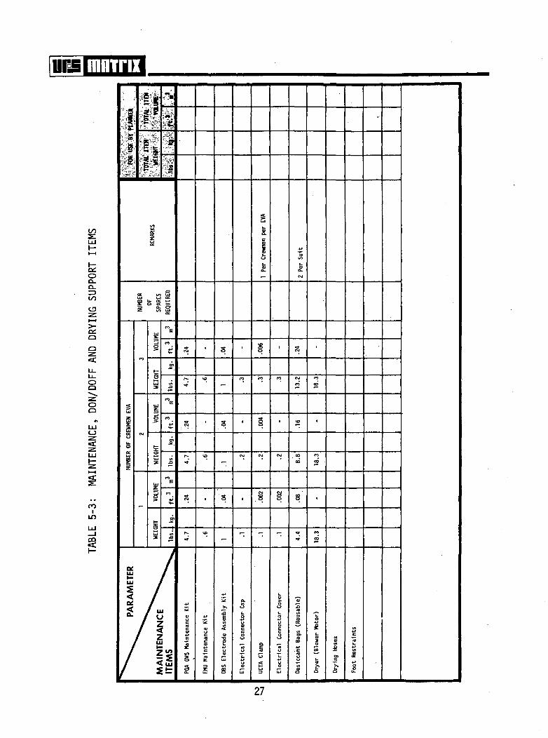
mnrrix5.3 MAINTENANCE, DON/DOFF AND DRYING SUPPORT ITEMS
Several items are required to support functions such as pressure suitdonning/doffing, drying after use, and maintenance in the event of damage ordeterioration while on orbit. Maintenance kits, suit drying hoses, connectorsand interior stabilization aids are among the most frequently required supportarticles. Each iteration in the development of advanced EVA equipment willrequire a complement of support items to ensure timely and efficient operationof the hardware. The weight and volume of each supporting item required willbe charged to the payload utilizing EVA. Many of the items are small and light-weight and might best be integrated into generic packages based on frequency ofuse, rapid accessibility, stowage configuration/availability, etc. Each EVAmission is studied individually to determine the type and quantity of supportitems required.
Table 5-3 provides information on the costs of a variety of EVA systemssupport items required for the Apollo and Skylab programs. Many of these orsimilar items are likely to be required on Shuttle-based EVA missions.
To use the table,
(1) Establish the number of crewmen that must be EVA to perform the task.
(2) Establish the number of EVAs that must be performed to accomplishthe selected task(s).
(3) Locate the column which corresponds to the number of crewmen EVAdetermined above.
(4) Obtain weights and volumes of individual components by descendingthe selected column.
(5) Establish the number of spare components required.
25
FTP! mnirn(6) Adjust individual item weights and volumes by multiplying entries
in the table after considering the number of EVAs and the numberof EVA suits (i.e., the number of crewman EVA) according to notesin the Spares and Remarks columns.
(7) Add individual entries down the "PLANNER" column to obtain totals.
26
\\m mnirix
OO.D_ratocu
oc:o
OO
OO
O
<c
coin
'11it?
£ 13
S
£
27
fflnirn5.4 LIFE SUPPORT SYSTEMS
According to current guidelines, the EVA Life Support Systems (LSS) usedon the Space Shuttle will consist of a self-contained, back-mounted portableLSS and/or an umbilical LSS with consumable stowage integrated into the totalspacecraft environmental control system (ECS). Present studies favor theportable type system used on the Apollo lunar surface exploration missions.The portable LSS will require modification to meet the requirements of theSpace Shuttle Orbiter and payloads.
The development of new LSS or modification of existing designs will allowselection -- by the Space Shuttle Program -- of basic LSS units/equipment foruse on all EVA missions. Similar to pressure suit selection responsibilities,a choice of primary EVA l,ife support systems will not be available to the pay-load planner — other than perhaps a choice between portable LSS or umbilicalLSS. Designation of the quantity of life support systems, inflight componentspares, expendables, etc. required will be the responsibility of the payloadplanning/designing teams of NASA and experimenters based on the specific pay-load requirements. The total weight and volume impact of the LSS to theexperiment is of primary interest to the Shuttle user. As a minimum, thefollowing life support system components are required when more than oneEVA is conducted during a mission:
t Portable Life Support System
- 1 primary LSS unit- 1 secondary (emergency) LSS unit- 1 spare CCL adsorbant for each LSS operation- recharge water- recharge oxygen (02)- battery recharge
• Umbilical Life Support System
28
mnrnx- 1 EVA umbilical assembly- 1 pressure control unit- 1 secondary (emergency) LSS unit
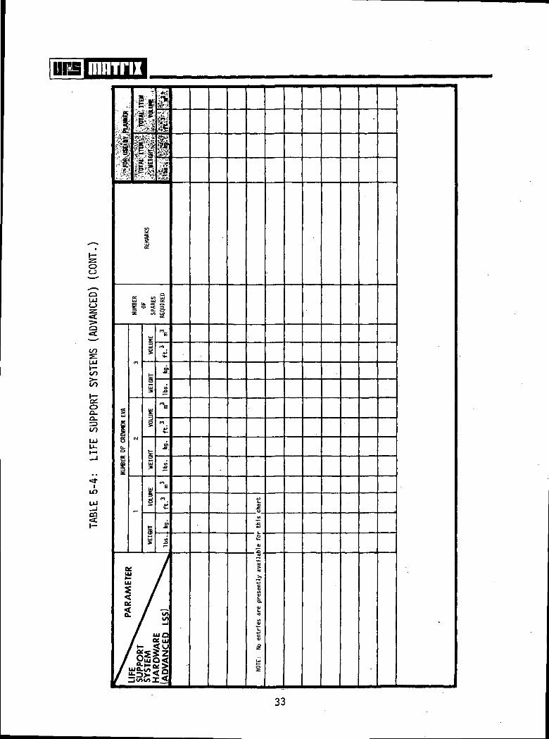
Table 5-4 provides data for estimating the weight and volume costs ofthe EVA life support systems. The values quoted in this table are based onApollo and Skylab systems with provisions for advanced life support systemsdata.
Table 5-4 is presented in two parts: (1) Portable Life Support Systems,and (2) Umbilical Life Support Systems. Since present concepts for ShuttleEVA are emphasizing portable systems, the portable systems receive primaryemphasis in this model. Umbilical systems are described in Table 5-4 assupporting information in the event these systems are included in some tasksor as backups to portable systems.
To use the table,
(1) Establish the number of crewmen required to be EVA to accomplishthe selected task(s).
(2) Establish the number of EVAs required to accomplish the selectedtask(s).
(3) Identify the column in either the portable or umbilical systemstable which corresponds to the number of crewmen EVA establishedabove.
i -
(4) Obtain component weights and volumes by descending the selectedcolumn to the row of the individual item.
(5) Establish the number of spare components required.
29

mnirix
(6) Adjust component weights and volumes by multiplying the valuesgiven by the number of EVAs required according to the Spares andRemarks columns. Other adjustments may also be required accordingto notes in the Remarks column. Record in "FOR USE BY PLANNER"column.
(7) Obtain total weight and volume of Life Support Systems by scanningdown the "FOR USE BY PLANNER" column after making adjustments asrequired by the Remarks column.
30

unsj. J
CO
co
co
CO
OD-
CO
CO
co
OQ.D-Z3CO
LO
LU
a
sHI^g%-!>
I!
Io
Vg-I
U) «0 00
Lf) CM <D
a •» »
I
£• 33</i
t I31

Tim mnirix
to
O
CO
OQ.Q.
CO
LULl_
LO
CO
r "
:|' 8 T*-i«,^»
1S
* •#
Ul
uU.O
Ul
c1<4
4
C4C
/
J•1W J
P
<*
ocUl
i <
l£ju
K
J(a
uiau."357
'I
f f
*Br?<o
REM
ARKS
SPAR
ES
u,
s
_§
ss
»?Uls
V
g
H-
UlX
/£•5)Si• ^•i-co»-><^.
n.\
!»*•j**.«&j*.
,iRE
QUI
RED
me
cn4-»it-
•S1.
J3
"E
CO
C
3
£
COE
fO
+J
**-
5>
M.£1
/
g3B*lSi
(U
s0»U
fe sc p3 <C_J fc.
^ VI'
1 1 1
WCO «3-M ^- VOCM CM CO
1 1 1
10 CVJ O
in to ror- - <M
, , ,
i i i
u> t rM CO M>
30 •— eor^ eo^
Oxy
gen
Um
bili
cal.
- L
eft
- C
ente
r-
Rig
ht
Ap
ollo
Tra
nse
art
h
•
•
0>
OJ•3-
•
1
*O •
COCM-
'
• •
to40
CO
^>
>»
3.toU
J3
Ul
O
i
atcO
1=("1
CO
4^<*-
OIO
m t—
2§
*»•
s s
«*• CMCM <M
in r
ss
-Qia
5*</)
(OU
4-*
1f 1^a;**• i i_i
n
esi
^
1 O
xyge
n U
mb
ilica
l H
ose
Cla
mp
S
B
t
Si
inin
s
3
1
Sec
onda
ry O
xyge
n P
ack
• •
1 1
r— 1C
§ S
• •
. •
^- ^~
S CMuo
• •
- •f- O>
CM *—
r-* CvJ
JS iS
4-*i15£ « £"3 3 0I/I(/I0) 1 I
.O«
5(/>
4-».COT
C1_Q)a.CNJ
«on
OGO
10
(*>
O
CO
«o(n
O
CO
k.OJc
1Ic3
Ii£3
£a.
-
J319
IfIS*
4-».Ccn
iZt.oa.
CSJ
CM
^
CO
oi
CSJ
^~
roat
CM
^>
CO
cn
1
Sec
onda
ry O
xyge
n P
ack
Con
tain
er
.a«
5CO
+>fCD
IZ
1
«*>r^
-.
ro
COr-^
*t
CO
COrx
•*
CO
I M
DA
U
mbili
cal
Conta
iner
32
*s*J
f
B-_ _
oCJ
to
CO
oO-o.to
g 3a, crV, g
ILf)
-•§-
33
rrra mmrnx5.5 CREWMAN TRANSLATION AND PACKAGE TRANSPORTATION AIDS
Numerous crewman translation and cargo transportation devices and systemswere proposed during previous space-flight programs for assisting the crewmanin his transfer tasks. Of the many transfer/transport systems conceived/developed, only a limited number remain as candidates for future space missions.These consist primarily of proven systems or those in the development/qualifi-cation stages for the Skylab and Space Shuttle Programs. Single and dual hand-rails of a specified cross section, compatible to the space suit gloves, havebeen efficiently used on previous EVA missions. Cargo transfer booms (i.e.,electrically powered extendible booms with manual backup) will be used duringthe Skylab EVA mission to retrieve scientific data inside film magazine con-tainers. An Astronaut Maneuvering Unit (AMU) and a Foot Controlled ManeuveringUnit (FCMU), to be evaluated on Skylab, offer potential free-flying systemsfor transferring man and cargo on the Space Shuttle and future programs. Itis anticipated that the crewman translation and package transportation aidswill not vary considerably from those currently available. The Space ShuttleOrbiter payload bay may, however, require some innovative concepts in orderto service the wide range of payload configurations and payload arrangementsinside the Orbiter bay. Only the weight of the EVA transfer/transportationsystems above those required for normal EVA crewman translation inside thepayload bay will be charged to the payload utilizing EVA. The Shuttle Orbiterwill provide mobility aids for EVA translation through the payload bay.
Table 5-5 provides weight and volume values for available crewman trans-lation and cargo transportation aids/devices. The crewman-only translationportion of the chart appears in the column where the package mass/volumeentry is 0/0. The 0/0 entry implies that the crewman transports only himselfand his attached support equipment.
Four major package size levels in terms of mass and a corresponding volumeare established by the columns in the table. The 0/0; <160/<10; 160-1600/10-140;
o oand >1600/>140 package mass/volume (in Ibs./ft. and kilogram/meter ) levelshave been demonstrated to be meaningful dividing points. The translation/
34
\\m mnirixtransportation aids which are considered appropriate for each package mass/volume region are designated with a check mark (y). The aids consideredinadequate for each region are designated with an (X). The assignments oftranslation/transportation aids to each region were made on the basis ofdemonstrated in-flight and simulation results.
To use the table,
(1) Establish the mass and volume of the package (item) that must betransferred.
(2) Identify the column heading within which the selected package falls.
(3) Obtain the least complex and least expensive translation/transporta-tion aid by identifying the first \/mark as the selected columnis descended.
(4) Obtain weight and volume estimates from the weight and volumecolumns of the row containing the selected translation/transportationaid.
Since the translation/transportation aid table is only a planning tool,extreme cases are not accommodated. Consequently, extremely cumbersome objectsand objects with small mass and/or small volume having awkward shapes cannotbe transported by the same aid as more standardized packages. In such casesthe next most complex transportation aid should be selected.
35

mnrrix
oI-H
a:oQ-co
o<:o.oS
CO
LO
LO
CO
g•g5
I
2S
red
to
ed t
o
ned
Co
ly A
c
If
s
'
Sa
i ms
36
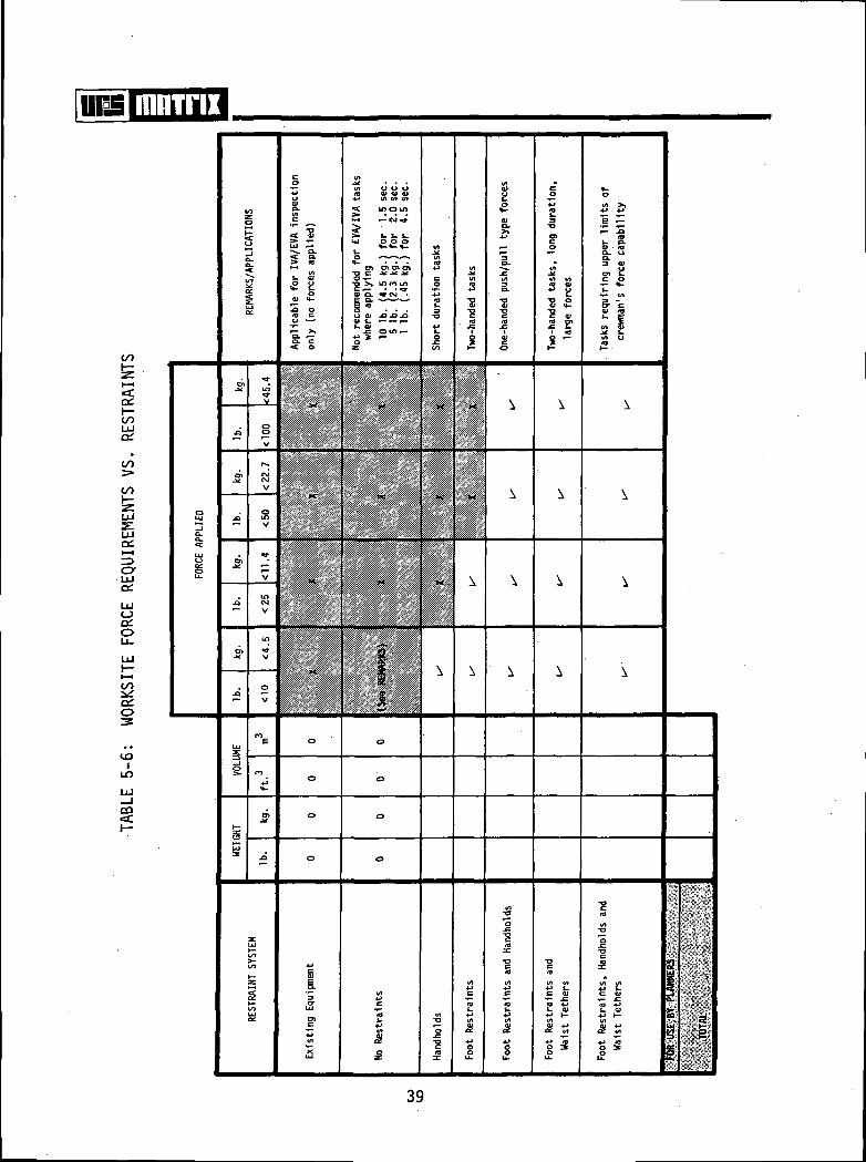
5.6 WORKSITE FORCE REQUIREMENTS VS. RESTRAINTS
The ability of the EVA crewman to exert the necessary forces in weight-lessness to perform required tasks is dependent upon the type of restraintsand stabilization aids provided at the worksite. In the zero-gravityenvironment, the EVA crewman must have a means of reacting all forces heimparts to the workpiece. Simple inspection, monitoring, and switch actua-tion (e.g., toggle switches, rotary switches, push buttons) can normally beperformed using existing (surrounding) equipment or with no restraints underconditions of low force (<1.0 lb.-<.45 kg.) and time (<4.5 sec.). Surroundingequipment frequently provides a quasi-grip area/protrusion satisfactory forthe low force/time tasks; however, this equipment should be used as a restraint
only after qualifying exercises (ref. 3.10).
The forces that must be applied to perform a required task can generallybe used to determine the type of restraint needed for that task. Table 5-6presents major force levels at which different restraint concepts have beenshown to be effective. However, if the crewman is required to perform activities(regardless of forces) at a worksite for a period of time, foot restraints mustbe provided. This will allow the crewman to function at the worksite withminimal energy expenditure for extended periods.
The accompanying table makes no allowance for the direction in which forcesare to be exerted. This is based on the fact that the force values given areconservative. Consequently, the crewman should be able to apply the forcelevel specified at the top of the column selected in virtually any direction,given that the task location is compatible with the worksite orientation andcrewman reach capabilities.
To use the table,
(1) Establish the level of force (Ib. or kg.) that must be applied toaccomplish a selected task(s).
37

(2) Locate the column which corresponds to the force level determinedabove.
(3) To obtain the least complex, least expensive system, identifythe first (/) mark reached as the column is descended.
(4) Obtain weight and volume estimates for the identified restraintsystem by locating the values quoted in the weight and volumescolumns of the row selected, making adjustments as noted in the"Remarks" column.
38
mninx
s_lQ_
s
a:
UJa;
c/)
8V
§oa:o
LU
o:o
10i
T3 C J*-*: .*<U •*-*o >* m ro mC •— • • *3-
1 *°
S O) .O J3 .O1. f—r- r-
i.
£
I
« u
•g £•g «•f I"i "
_E r-
^ S.
§:
si
I1
^M(/)
5i
39
5.7 PRE-EVA CREW TIME
The time required for the crewmen to prepare the spacecraft systems andthe EVA support hardware for external activities is directly related to theefficient design of the man/system interface, the number of manual operationsrequired, the location of the items used in the preparation functions, etc.The preparation time required for EVA on previous missions has acted somewhatas a deterrent in selecting EVA for future missions. The donning of the EVAgear is only a moderate fraction of the time required as compared to vehicleand EVA systems checkout and preparation. The incorporation of smaller air-locks, advanced EVA support systems (e.g., life support system, pressure suits),and collocation of EVA associated items and functions on future missions isdesigned to reduce the preparation and termination time. Crewman prebreathing(pure oxygen to prevent dysbarism) time will be eliminated, according to current
pguidelines, through the use of high pressure (8 psi - .56 kg./cm. ) suits.Prebreathing time has been a significant factor on previous EVAs. The numberof crewmen required to participate in EVA, the number assisting in EVA pre-paration, and the duration of each EVA will affect the total preparation time.
Table 5-7 is provided to allow an estimate of crew time required for EVApreparation. Values are given for facility preparation, suit donning, lifesupport system donning, airlock depressurization, etc. The values given arefor the A7L-B, PLSS, and umbilical systems (unshaded areas) used on Apolloand Skylab, as well as the advanced extravehicular suit (8 psi) and the advancedlife support system (shaded areas). The times shown in the unshaded areas arebased on simulation time associated only with the item listed and contain noother concurrent vehicle or systems functions. The shaded areas contain grossestimated times of EVA systems in the advanced development stage withouthaving been verified through simulations or space flight.
i
To use the table:
(1) Establish the duration of the EVA required to accomplish the selectedtask(s).
40
m=\ Hurra(2) Establish the number of crewmen that must be EVA to perform the task
and number of supporting crewmen.
(3) Locate the column which corresponds to the EVA duration, number ofcrewmen EVA, and number of crewmen assisting, established above.
(4) Add pre-EVA times proceeding down the appropriate column.
(5) Add times for each major activity to obtain total pre-EVA time.
Pre-EVA time includes all operations from the time the crewman beginsEVA preparation until the airlock hatch is egressed. It should again benoted that the times included in the table are estimates based on previousEVA missions and simulations for Skylab, then "projected" to future missions.
41

mnrnx
coGC.
o;
<
a:a.
to
tr?
p
«
uns
s y,
Ic
i
y, i
34-*
i
9NINNOQ W31SAS IMOddHS 3JH
42
El] mnirw5.8 POST-EVA CREW TIME
The factors which determine EVA termination time (i.e., post-EVA time)include EVA equipment doffing, EVA support systems recharging/drying, equip-ment stowage, and vehicle systems post-EVA operations. The equipment andsystems are serviced as quickly as practical following EVA in order to haveoperational hardware available for contingency circumstances and futurescheduled EVAs. As in the preparation for EVA, the number of crewmen requiredin EVA functions, the number assisting in EVA termination, and the durationof each EVA will affect the total termination time.
Table 5-8 is provided to allow an estimate to be made of the crew timerequired after EVA tasks are complete. Values are given for airlock pressuri-zation, suit doffing, equipment servicing, etc. The times given in the tableare specified for the A7L-B and the advanced suit (8 pst); times in the shaded/unshaded areas are explained in Section 5.7, p. 40.
To use the table:
(1) Establish the duration of the EVA required to accomplish theselected task(s).
(2) Establish the number of crewmen that must be EVA to perform the taskand the number of supporting crewmen.
(3) Locate the column which corresponds to the EVA duration, number ofcrewmen EVA, and number of supporting crewmen established above.
(4) Add post-EVA times proceeding down the appropriate column.
(5) Add times for each major activity to obtain total post-EVA time.
Post-EVA time includes all activities from the time the exterior airlockhatch is ingressed until the crewman is prepared to start another type of
43

mnirixactivity. It should be noted that the times included in the table areestimates based on previous EVA missions and simulations for Skylab, then"projected" to future missions. Many options are available for efficientlyperforming other tasks during post-EVA functions and should be consideredrelative to the total space mission.
44

\\m BBTTII
t/)Qi
c/ooO-
00
to
COef.
-pie <o
g-fe
M
3NUJOO DNUJOQ W31SAS J.)iOddnS 3JP
'145

[IE] mnTnx5.9 CONSUMABLES AND EXPENDABLES
The expendables required by the EVA life support system (LSS) and pressuresuit, and the consumables used by the crewmen must be considered when derivingthe total cost of EVA to a space program. The design of systems to supplystowage (e.g., tankage, containers, plumbing) of the consumables and expendablesis normally the responsibility of the primary vehicle designers, while theelements being used are considered part of the total EVA supporting require-ments. The consumables required by the EVA crewman include oxygen ((L) forbreathing and drinking water for long duration EVAs. The expendables requiredfor the current LSS include cooling water for the Liquid Cooling Garment (LCG),lithium hydroxide (LiOH) for carbon dioxide (CCL) control, and charcoal fortrace contamination control. Advanced LSS may require a variety of expendablesor refurbishables such as ice packs, chlorate candles, magnesium hydroxide,zinc oxide, etc. The pressure suits also have a small percentage Og loss fromleakage that is considered in the expendable calculations. The quantity ofexpendables and consumables for EVA are, of course, based upon the EVA durationand number of crewmen required.
Table 5-9 provides data on the weight and volume of consumables andexpendables that must be provided for EVA. The values given in the tableare based on Apollo and Skylab systems with provisions for including theweight and volumes of advanced systems.
To use this table:
(1) Establish the duration of the EVA required to accomplish theselected task(s).
(2) Establish the number of crewmen that must be EVA to perform the task.
(3) Locate the column which corresponds to the EVA duration and numberof crewmen EVA established above.
46
mum!(4) Obtain individual consumable or expendable weights and volumes by
descending the selected column. Data shown is for one unit andmust be multiplied by the number of units required. Total consumableand expendable weights and volumes are calculated at the bottom ofthe selected column by the user.
47

da mnirii
CQ
Q.X
CQef.
oo
ILO
CO
ill 1t g =1 I-
S319VQN3dX3
48

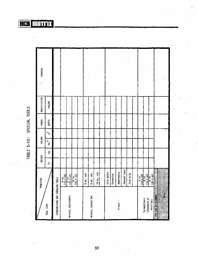
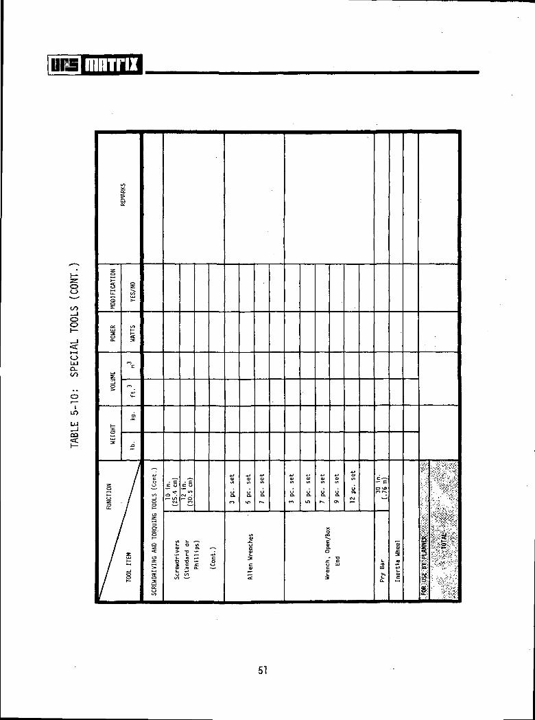
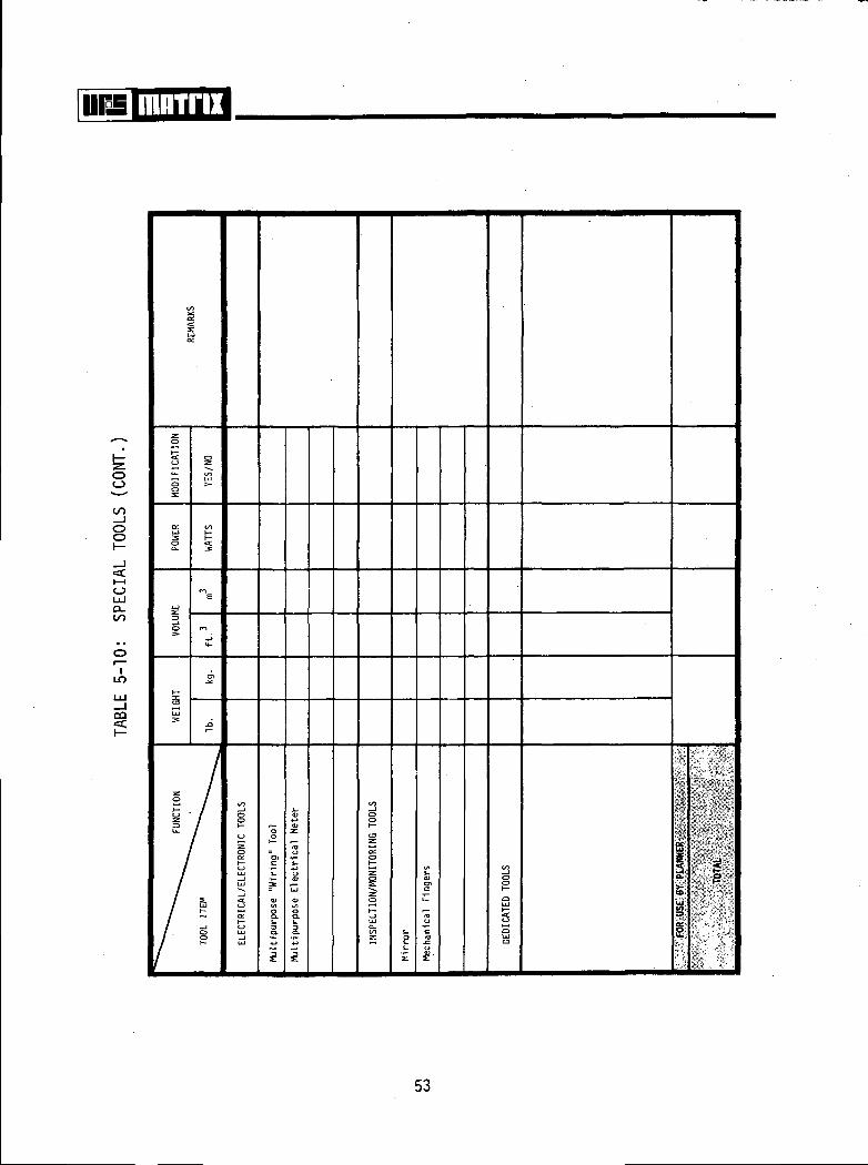
m=\ mnirix5.10 SPECIAL TOOLS
A variety of tools may be required to perform vehicle and payload taskswhile EVA. Several special "zero" and reduced reaction power tools have beendesigned and tested for use on previous orbital missions. Only a minimum ofthese tools were flown, but they may have application on future missions intheir present configuration or through slight modification. However,experience from previous orbital EVA missions indicates that if the crewmanis properly restrained, most EVA tasks can be accomplished with hand tools.Further, many off-the-shelf industrial/consumer tools can be used with minormodifications to enhance handling/gripping and to prevent loss by "floating"away.
A representative small tools listing is provided in Table 5-10 to assistin estimating the weight, volume, and power cost to the vehicle/payload. Manyof the tools listed in Table 5-10 are of the types used on previous orbitalmissions or scheduled for Skylab intravehicular activities (IVA). The manypowered and special application tools are not included in the listing.Sufficient space is included in the table for listing of dedicated tools.Each EVA man/system interface task must be studied to determine the following:(1) are tools required, (2) are off-the-shelf tools adequate, and (3) ifspecial power tools are required, can existing units be used to avoid researchand development costs.
Using Table 5-10 requires only that the planner identify the type andquantity of tools needed, and record the total in the space provided.
49
00_loo
oUJQ-
IIT)
00«£
§
s
soac.
3•S£
50
i\m mnrnx
oo_ioo
oLLJQ-to
ILO
CD
51

IHTTIZ
oo
oo
<cI—IoUJQ.
ILT>
OQ•=C
3
52
oo
oo
oLUQ.to
ILO
CO
8OUl
s
53
5.11 EVA CREWMAN OPERATIONAL ENVELOPES
Considerations given to the envelopes required for the crewmen with EVAequipment to translate, ingress/egress, maneuver, etc. are important in thelocation and arrangement of equipment involving EVA operations. The locationof EVA airlocks and hatches with respect to surrounding equipment, or viceversa, must allow sufficient room for ingress/egress with EVA equipment. Thearrangement of payloads in the Shuttle Orbiter bay requires study if EVA isused for payload servicing. The translation route to the worksites andsufficient working volume at the sites are also factors in "designing forEVA". The area required for package transfer is, of course, based on the over-all package dimensions. Simulations indicate that the passageway should be aminimum of TBD% over that of the package being transferred.
Table 5-11 provides an estimate of the envelopes necessary for the crew-man to effectively and efficiently perform EVA functions. Table 5-11 shouldbe referenced during the early phases of vehicle design and payload arrangement.
54

mninx
CL.O
EO
"8O >
««- O.
V) UVI O)
t- r-"p*o t
0)O) 01C
(ft OO) f-
10 O» I-(H U
i0 O O)ffl-C t.
ce:o_o
a:o
"S (U
CD 0» ON
J2 o! Sr~&. cn i« <o l- ;
J^ ttJ TO T3 'ito ••- :
O) C O Cto o tJ> •»-
iLO
CQ•=£
sLU
toto£
RANS
FER
(Pa
Long
Hud
ina
55
mmnx
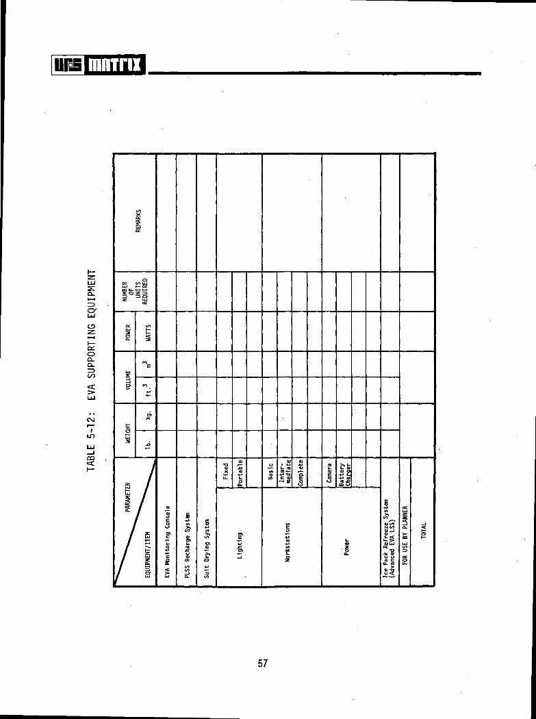
5.12 EVA SUPPORTING EQUIPMENT
The major systems (e.g., life support system, pressure suits) whichprovide direct support to the EVA crewmen will themselves require a complementof equipment for checkout, monitoring, and servicing. The portable lifesupport systems used will require a means of verifying operational statusprior to EVA, minor repair in the event of component malfunction, and servicing(i.e., replenishing expendables) operations following EVA. The pressure suitswill require provisions for repairing suit components and for drying/servicingthe suit following EVA/IVA operations.
A number of critical body functions and equipment performance parameterswill be monitored and recorded during EVA for the safety of the crewman. Func-tions monitored will normally include heart rate, C02 status, 0« flow rate, 02pressure, time, voice, etc. An EVA monitoring station/console will be requiredinside the vehicle to perform these operations. The weight, volume, andnumerous systems interfaces will impact the vehicle and payloads.
Supporting equipmsnt for "servicing" advanced EVA systems may includehardware such as ice pack refreeze systems (refrigerator) for life supportsystems, checkout system for pressure suit outer contamination garment, servic-ing hardware for regenerable LSS, etc. Systems of the above nature are notcurrently available for future EVA missions; however, preliminary studies havebeen conducted in many areas involving EVA support systems. Some spin-offsof these type studies may be incorporated into the Shuttle Orbiter EVA systemsand should be closely followed to determine possible vehicle and payload impacts.
Table 5-12 provides estimates of the weight, volume, and power requiredto include several of the EVA supporting equipment items aboard a vehicle.The "cost" estimates are given for the total supporting unit but are subjectto subsystem breakdown in future studies. The required supporting items areidentified and the cost (e.g., weight, volume) multiplied by the number ofunits needed to arrive at a total cost.
56
mnrnx
a.i—iZ3cy
SfeSS
oD-O.
CO
«c
ILT>
CQ
3
iai -o0«t
57
rn mninx5.13 EVA COSTS SUMMARY
A summary chart/master worksheet is provided to allow the user to recordand obtain a total estimated cost of EVA to a future program. Each ofthe major costs in terms of weight, volume, crew time, power, etc. can besummarized individually on the master worksheet. The individual worksheetscan be used as a checklist for identifying a complement of necessary EVAsystems/hardware.
The EVA tasks and number of EVAs needed are identified from the uservehicle and payload requirements. These requirements are compared to the EVAcrewman's capabilities from the information contained in Section 4.0 of thisreport and other pertinent documentation. From this information the number ofEVA crewmen required, the EVA duration, and the EVA equipment needed areestimated. The individual EVA equipment Cost Model sheets are then used toestimate the cost of each item or operation associated with EVA.
The EVA time (i.e., the total amount of time required to perform thetasks and translate to and from the worksite) must be estimated. This time isthen added to the pre- and post-EVA times to derive a total EVA crew timeestimate.
The summary chart is subdivided into two (2) sets of cost elements.Set one contains those EVA systems/elements which have a weight, volume,power, or crewman time impact to the mission, vehicle, or payload. The settwo elements have either a crewman time or dimensional impact.
58
mnrnx
ooo
iLT>
co
ot—Q.
C£.
UJO
1
to
sUJ
u.O
XUJ
Z
IO31
0
•a:
§Vao
gj—COUJ
1 NU
MBE
R CR
EWM
EN
REQ
UIRE
D
OL
UJXL
t—
I
UJg
g
Ul
ini.3
"E
ro
*-
J7
5
to
UJ—1 t—UJ Ul
toCO "~*s
(Ua.
CO
toUJu
CO Z
o; QJ0 Q.tO >v
>
00
Ul
5
go
UJ
UJ£
1STOW
AGE
SUPP
ORT
EQU
IP
(All
Equ
ipm
ent)
1
MAI
NTE
NAN
CE.
DO
N/ D
OFF
DR
YIN
G
EQUI
PMEN
T
(All
Equ
ipm
ent)
£</j to
h- O.CO
CO
a.CO
Ulu.
to
_JCD C.
CONS
UMAB
LES
AND
EXPE
t
Cre
vi
iVI
CO
59

Oo
o
=£UJ
CO
LO
UJ_l
CO
iOC.
LU
1—
ex:UJ
D_
UJ
O
(_
LU
io
CO
"a
ro
<*-
j?
.a
CO
LUx — •_lLU r-
H- W
§ ~
s
^N
TRAN
SLAT
ION
AND
CAR
TRAN
SFER
AID
S
Handra
ils N
o
Han
dhol
ds N
o
uo.£
11 *cxo
301
^3
.1U.
2
CO
§—1 i,•a: 01 -o
tu a. zexCO
at'oV)
SUPP
ORT
ING
EQ
UIPM
ENT
EVA
Monito
ring
Con
s•M
a>
tou
CO
a.
g
enc
o
to
c0
Wor
ks ta
ti
e•f,
V)
at
o
s
REST
RAIN
TS Tet
hers
No.
1|
60

fflBinx
•zr
O0
Q-:<=c
ZDoo
1 —oo
^1 1 1
• •CO
inUJ
CD
1—
51—
1
_JO
UJ
g
C/l
o
UJ
o
UJT£.UJ
UJ
1—*/)oO
S2o:
UJon
o
1ro
4-
CME
C\J
**~
E
c
(VI
^_UJ
UJQ.o_JUJ
UJ
3 00^ -Jf—SUJO-0
§ 3a.
io
<Jo
5
Co
-M<O
c
£h-
VI
3in
t-
I-CaITJ
a*
o
cUJ
JZ
^JITS
in
C71
UJ
£i.c
co
+-»lt>
1
a>
'o
01c
1co+3ID
(A
1
UJ
P
^UJ £a: SO UJ
o;
UJ •
ccQ.
s1—X S£UJ UJ
CJ S
> oUJ
fe £Oa.
(A
UJ
l—
2S
4-*
s
QCUJg
°-
CO
4-1if.
w§
(/) i~o ^--(J(/I
UJ
5;
S §O UJ
61

\\m mnrnx
REFERENCES
3.1 NASA Manned Spacecraft Center: Preliminary Design Requirements for ShuttleEVA/IVA Orbiter Support, MSC01497, September 30, 1971.
3.2 URS/Matrix Company: Skylab EVA Task Analysis, Contract NAS8-25627,Huntsville, Alabama, August 1971.
3.3 Manned Spacecraft Center: Gemini Summary Conference, NASA SP-138,Houston, Texas, February 1-2, 1967.
3.4 Loats, H. L., G. S. Mattingly, and G. M. May, Correlation Study of theSimulation of Gemini Extravehicular Activity With Flight Results, NASA
CR-1146, February 1969.
3.5 Manned Spacecraft Center: Preliminary Flight Plan—Apollo 15, MSC CrewProcedures Division, Houston, Texas, December 1971.
3.6 Beasley, J. C., Extravehicular Maneuvering in Space, AA/NASA, LangleyResearch Center, Hampton, Virginia, 1966.
3.7 Spady, A. A., G. P. Beasley, and K. R. Yenni, Preliminary Results of MannedCargo Transfer Studies Under Simulated Zero-g Conditions, AIAA/ASMEWilliamsburg, Virginia, August 9-11, 1971.
3.8 Smith, A. F., Verbal description of MSC simulation activities provided at
Contract NAS9-12997 midterm review, November 30, 1972.
3.9 Brown, N. E., T. R. Dashner, and B. C. Hayes, Extravehicular ActivitiesGuidelines and Design Criteria, NA-SA CR-2160, January 1973.
3.10 Mattingly, G. S. and H. L. Loats, Study of Astronaut Restraints and MobilityAids in a Weightless Environment, URS/Matrix Company, Contract NAS9-12574,
September 27, 1972. 62