cargo handling book 2016
DESCRIPTION
MacGregor's cargo handling solutions for container ships, general cargo vessels and bulk carriersTRANSCRIPT
1
Cargo handling solutions for container ships, general cargo vessels and bulk carriers
Cargo Handling Book 2016

Passion for performance – united by the seaMacGregor is a family of innovators. By engineering solutions that make the sea more accessible, safe and reliable, we support you whose livelihood depends on the changing conditions of the sea. To enable that we have a variety of strong product brands and committed experts with a passion for solving challenges – and the power of the sea is sure to provide those.
Our founders braved new frontiers in different times and places. Those origins merge at today’s MacGregor, inspiring us to continue the stories, and create new ones. The spirit of our founders lives on in the pride we have for what we do, and our determination to find new solutions for the people we work with. Together with you we will write the next chapters.
We are a global team of professionals, who create value for you; the shipbuilders, owners and operators,
in the offshore and marine industries. Understanding your business and way of life is key to our work. It is the foundation to addressing your needs with tailored solutions for load handling, cargo handling, mooring or essential auxiliary equipment. Your productivity, sustainability, and equipment lifetime benefit from our combination of expertise and technology. As innovators, we work together with you to set benchmarks in innovative solutions and value creation. Our deep respect for and experience of the sea lays the foundation for adapting to its challenging conditions. Wherever we work around the world, we work together with a passion for performance and a love of challenges — united by the sea. Our shared values - integrity, quality and safety - propel us forward, and are an important factor in our ability to continue to deliver what our customers need to succeed; solutions that are designed to perform with the sea.
4
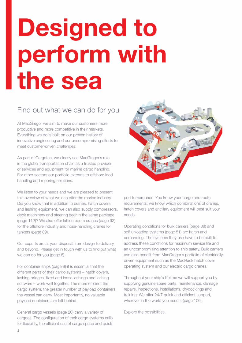
Designed to perform with the sea
port turnarounds. You know your cargo and route requirements; we know which combinations of cranes, hatch covers and ancillary equipment will best suit your needs.
Operating conditions for bulk carriers (page 38) and self-unloading systems (page 51) are harsh and demanding. The systems they use have to be built to address these conditions for maximum service life and an uncompromising attention to ship safety. Bulk carriers can also benefit from MacGregor’s portfolio of electrically-driven equipment such as the MacRack hatch cover operating system and our electric cargo cranes.
Throughout your ship’s lifetime we will support you by supplying genuine spare parts, maintenance, damage repairs, inspections, installations, drydockings and training. We offer 24/7 quick and efficient support, wherever in the world you need it (page 106).
Explore the possibilities.
At MacGregor we aim to make our customers more productive and more competitive in their markets. Everything we do is built on our proven history of innovative engineering and our uncompromising efforts to meet customer-driven challenges.
As part of Cargotec, we clearly see MacGregor’s role in the global transportation chain as a trusted provider of services and equipment for marine cargo handling. For other sectors our portfolio extends to offshore load handling and mooring solutions.
We listen to your needs and we are pleased to present this overview of what we can offer the marine industry. Did you know that in addition to cranes, hatch covers and lashing equipment, we can also supply compressors, deck machinery and steering gear in the same package (page 112)? We also offer lattice boom cranes (page 92) for the offshore industry and hose-handling cranes for tankers (page 89).
Our experts are at your disposal from design to delivery and beyond. Please get in touch with us to find out what we can do for you (page 6).
For container ships (page 8) it is essential that the different parts of their cargo systems – hatch covers, lashing bridges, fixed and loose lashings and lashing software – work well together. The more efficient the cargo system, the greater number of payload containers the vessel can carry. Most importantly, no valuable payload containers are left behind.
General cargo vessels (page 20) carry a variety of cargoes. The configuration of their cargo systems calls for flexibility, the efficient use of cargo space and quick
Find out what we can do for you
5
ContentsContainer ships ............................................................. 9
Lift-away hatch covers............................................ 12
Lashing bridges ...................................................... 16
Loose and fixed container fittings, lashing bridges, lashing mock-up tests and software ....................... 17
MacGregor PlusPartner .......................................... 18
General cargo vessels ................................................. 20
Folding hatch covers .............................................. 26
Lift-away hatch covers............................................ 28
Piggy-back hatch covers ........................................ 30
Stacking hatch covers ............................................ 31
Pivoting hatch covers ............................................. 31
Tweendecks and movable bulkheads ..................... 33
Tweendeck consoles and pockets .......................... 35
Bulkhead sealing gear ............................................ 37
Bulk carriers ................................................................ 38
Folding hatch covers .............................................. 42
Rolling hatch covers ............................................... 43
Electric drives ......................................................... 47
Gravity self-unloading systems for bulk carriers ...... 51
Cement carriers ........................................................... 54
Versatile self-unloading systems for cement carriers ................................................. 54
Horizontal and vertical screw conveyors for cement carriers ................................................. 56
Hatch cover load transmission ..................................... 58
Flexipad, Polypad, Lubripad, Unipad, Steelpad, Fixpad .................................................... 58
Sealing solutions .......................................................... 61
FlexSeal, Cat Profile, Sponge, C Gasket, Omega, Omega lite ................................................ 62
Selection and operation of our seals ....................... 62
Which seal type for which ship type? ...................... 63
Glues and greases ....................................................... 63
Hatch cover control systems ....................................... 65
Hydraulic control systems ....................................... 65
Soft starts ............................................................... 68
Radio remote control .............................................. 70
Complete steel structures ............................................ 73
Crane production ......................................................... 78
Cranes for all ship types .............................................. 79
GL crane ................................................................ 80
GLE crane .............................................................. 81
GLB crane .............................................................. 82
GLBE crane ............................................................ 83
GLH crane .............................................................. 84
GLHE crane............................................................ 85
K4 crane ................................................................ 86
General purpose (GP) crane ................................... 88
Hose handling (HH) crane ....................................... 89
LC crane ................................................................ 90
Port cranes ............................................................. 91
Lattice boom crane ................................................ 92
Crane Control Systems........................................... 93
Human Machine Interface ...................................... 94
Accessories and extras .......................................... 95
Active rotation control (ARC) ................................... 96
Off-line pump/filter ................................................ 107
Oil cooler .............................................................. 108
CC3000 Control System....................................... 109
Emergency Box .................................................... 110
Crew training ........................................................ 111
Lifecycle support from MacGregor ............................ 106
Deck machinery for every ship .................................. 112
Steering gear and compressors ................................ 113

6
Contact Us:Cargo Material HandlingMacGregor Sweden ABSjögatan 4 GSE-891 85 Örnsköldsvik,SwedenTel: +46-660-294 [email protected]
Cargo Stowage & SecuringMacGregor Finland OyHallimestarinkatu 6FI-20780 Kaarina, FinlandTel: +358-20-777 [email protected]@[email protected]
Securing SystemsMacGregor Germany GmbHReichsbahnstrasse 72DE-22525 Hamburg, GermanyTel: +49-40-25 444 [email protected]
MacGregor Pte LtdNo 15 Tukang Innovation Drive,618299 Singapore Tel: +65-6597 [email protected]
Auxiliary and Machinery Systems MacGregor Hatlapa GmbH & Co. KGTornescher Weg 5-725436 Uetersen, GermanyTel: [email protected]
MacGregor Pusnes AS368 Skilsøveien, Pusnes, NO-4818 Faervik, Norway Tel: + 47-370-873 [email protected]
MacGregor Pusnes ASDokkveien 10, PorsgrunnPO Box 1714NO-3998 PorsgrunnNorwayTel: +47-35-93 12 [email protected]
ChinaShanghai Office:Tel: +86-21-2606 3000
South KoreaBusan Office:Tel: +82-51-709-3777
Singapore Office:Tel: +65-6597 3888
JapanTokyo Office:Tel: +81-3-5403 1966
GermanyHamburg Office:Tel: +49-40-254 440
www.macgregor.com

7
www.youtube.com/macgregor
http://i.youku.com/MacGregor
http://issuu.com/cargotec
8
9
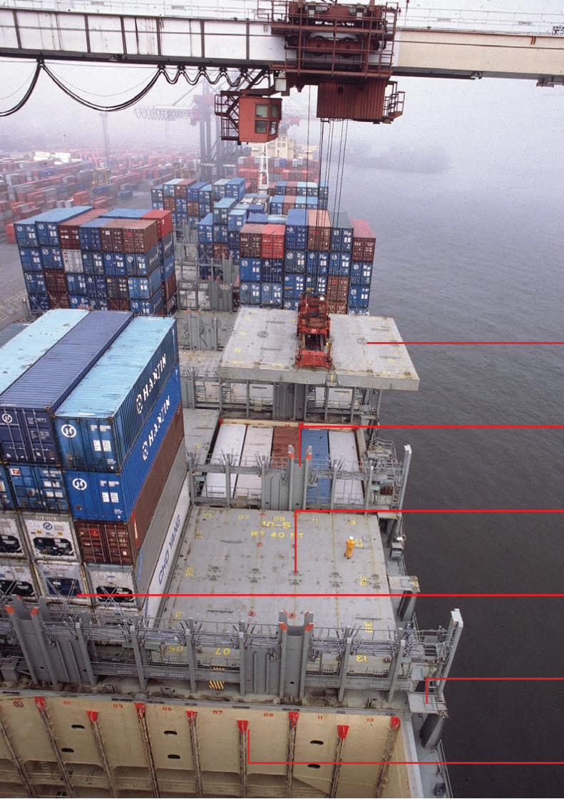
The best container stowage solutions are built around their intended cargoAn efficient container stowage solution can only be achieved by treating the ship’s hull and its cargo handling system as a single optimised entity. Consequently, parts of the container stowage system, such as the hatch covers, lashing bridges, container stanchions, loose and fixed container fittings on deck and in the holds, and the cell guide system in the cargo holds, should be considered from an overall container stowage solution point of view, not as separate products.
MacGregor is unique as the only supplier who can design and deliver all these products, enabling us to take a whole-ship approach and make the most of each ship’s container stowage system.
Built-in efficiencyThe more efficient the container stowage solution is, the greater the number of payload TEUs a ship can carry, which, in turn reduces the cost and emissions per carried TEU and subsequently per transported commodity, and at the same time increases the ship’s profitability and income.
Cell guides in hold
Container stanchions
Loose container fittings (twistlocks,
lashing bars, turnbuckles)
Hatch covers
Lashing bridges
Container fittings on deck
Container ships
10
Container ships
Lift-away hatch covers
Lashing bridges
Fixed container fittings
Loose container fittings
Container stanchions
Cell guide systems in hold and on deck
Lashing mock-up tests to verify performance
Lashing software
Complete hatch cover and lashing bridge steel structure manufacturing
GL cargo crane
GLE cargo crane
LC cargo crane
Steering gears
Compressors
Deck machinery
Global lifecycle support
MacGregor PlusPartner solutions
MacGregor knows how to get all the parts of a cargo handling system to work in unison, ensuring that a vessel sails with the best possible performance.
11
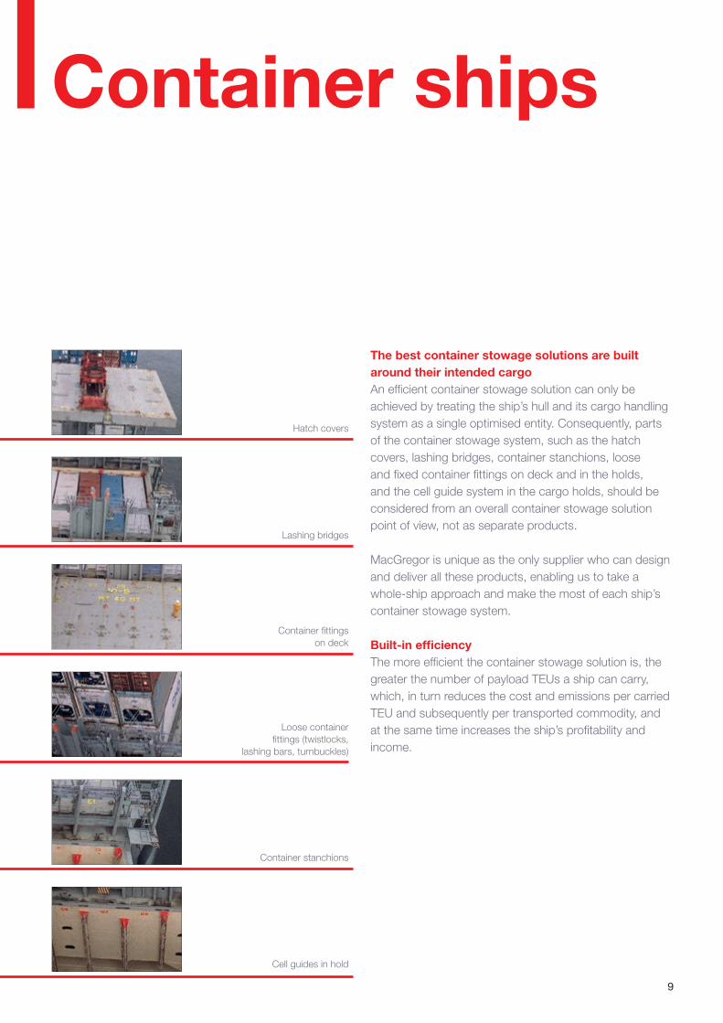
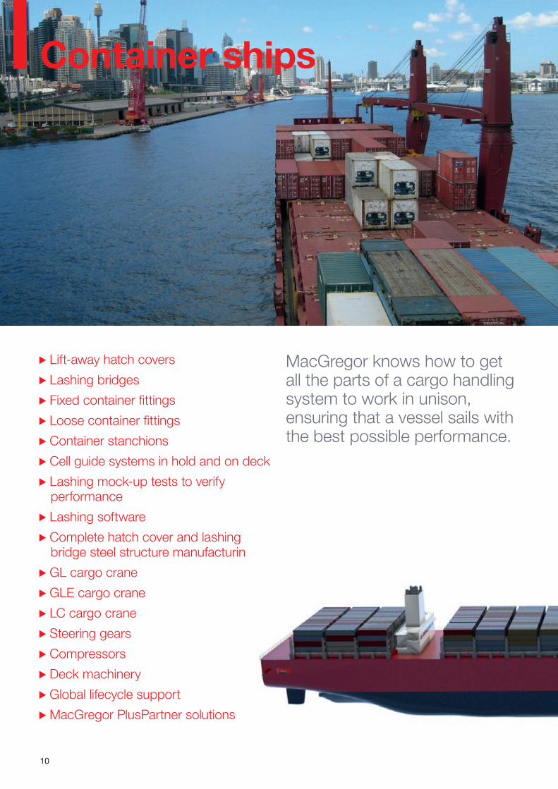
The design criteria for a feeder vessel’s container stowage solution differ completely from the criteria for an ultra large container carrier, and so do their container securing systems. Whatever the size of the vessel, MacGregor knows how to design and deliver an efficient cargo handling and stowage system for containerised cargo.
MacGregor knows how to get all the parts of a cargo handling system to work in unison, ensuring that a vessel sails with the best possible performance.
Building a new container vessel is a major investment and the decisions taken at the early design phase will define the loading capacity throughout the vessel’s lifetime. Optimisation of the loading capacity can lead to increased earnings. For example, with an improved system the vessel may be able to carry one extra tier of loaded containers.
MacGregor can advise shipowners from the outset, at the earliest point when ideas for a new vessel are conceived. It can be a design expert during the project through to delivery, and a service partner throughout the vessel’s lifetime.
MacGregor’s involvement at an early stage makes it possible to achieve an optimised custom-made container stowage solution, with a lashing system designed for all operational criteria. The design of the container stowage solution for a new vessel involves many different steps. MacGregor knows what is needed to ensure that all parties get the correct information at all stages of the project. It can deliver a total solution, including all documentation from the whole system through to the final equipment details, from layout to offset plans.
Before the final design is fixed, MacGregor performs a full-scale mock-up test to verify the performance of the lashing system. MacGregor considers elements such as the locations of handrails and other structures that might interfere with lashing equipment. When everything is designed, tested, manufactured and approved, all relevant documentation is made available in the cargo securing manual, which is needed on board for the vessel’s maiden voyage.
12
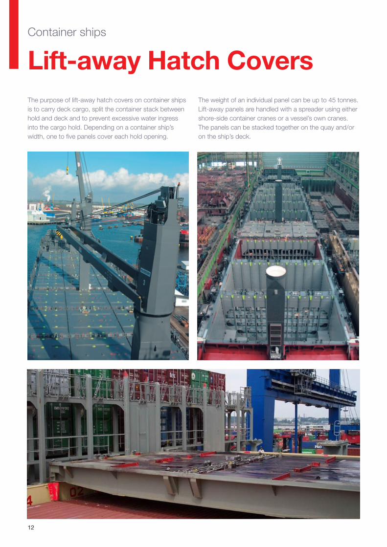
Lift-away Hatch CoversContainer ships
The purpose of lift-away hatch covers on container ships is to carry deck cargo, split the container stack between hold and deck and to prevent excessive water ingress into the cargo hold. Depending on a container ship’s width, one to five panels cover each hold opening.
The weight of an individual panel can be up to 45 tonnes. Lift-away panels are handled with a spreader using either shore-side container cranes or a vessel’s own cranes. The panels can be stacked together on the quay and/or on the ship’s deck.
13
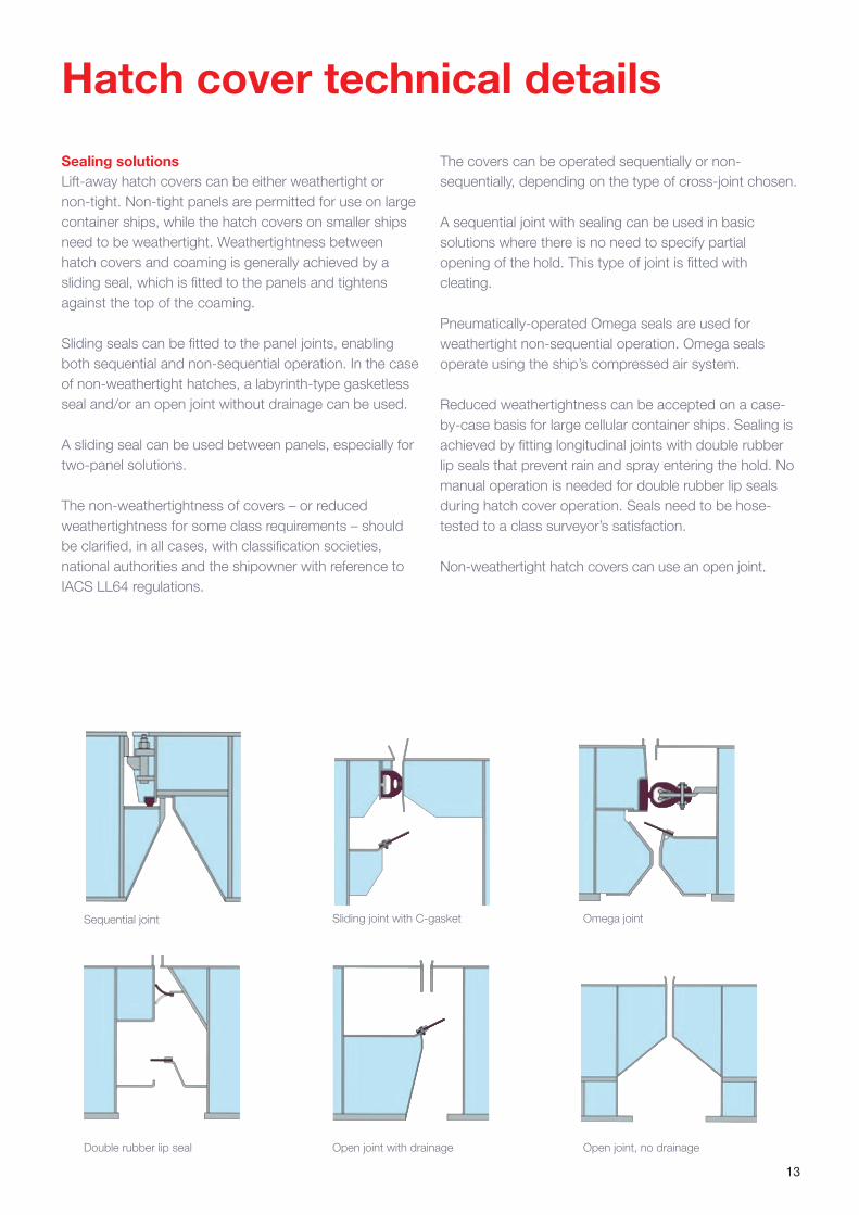
Sealing solutionsLift-away hatch covers can be either weathertight or non-tight. Non-tight panels are permitted for use on large container ships, while the hatch covers on smaller ships need to be weathertight. Weathertightness between hatch covers and coaming is generally achieved by a sliding seal, which is fitted to the panels and tightens against the top of the coaming.
Sliding seals can be fitted to the panel joints, enabling both sequential and non-sequential operation. In the case of non-weathertight hatches, a labyrinth-type gasketless seal and/or an open joint without drainage can be used.
A sliding seal can be used between panels, especially for two-panel solutions.
The non-weathertightness of covers – or reduced weathertightness for some class requirements – should be clarified, in all cases, with classification societies, national authorities and the shipowner with reference to IACS LL64 regulations.
Open joint, no drainage
Sequential joint Sliding joint with C-gasket Omega joint
Double rubber lip seal Open joint with drainage
Hatch cover technical details
The covers can be operated sequentially or non-sequentially, depending on the type of cross-joint chosen.
A sequential joint with sealing can be used in basic solutions where there is no need to specify partial opening of the hold. This type of joint is fitted with cleating.
Pneumatically-operated Omega seals are used for weathertight non-sequential operation. Omega seals operate using the ship’s compressed air system.
Reduced weathertightness can be accepted on a case-by-case basis for large cellular container ships. Sealing is achieved by fitting longitudinal joints with double rubber lip seals that prevent rain and spray entering the hold. No manual operation is needed for double rubber lip seals during hatch cover operation. Seals need to be hose-tested to a class surveyor’s satisfaction.
Non-weathertight hatch covers can use an open joint.
14
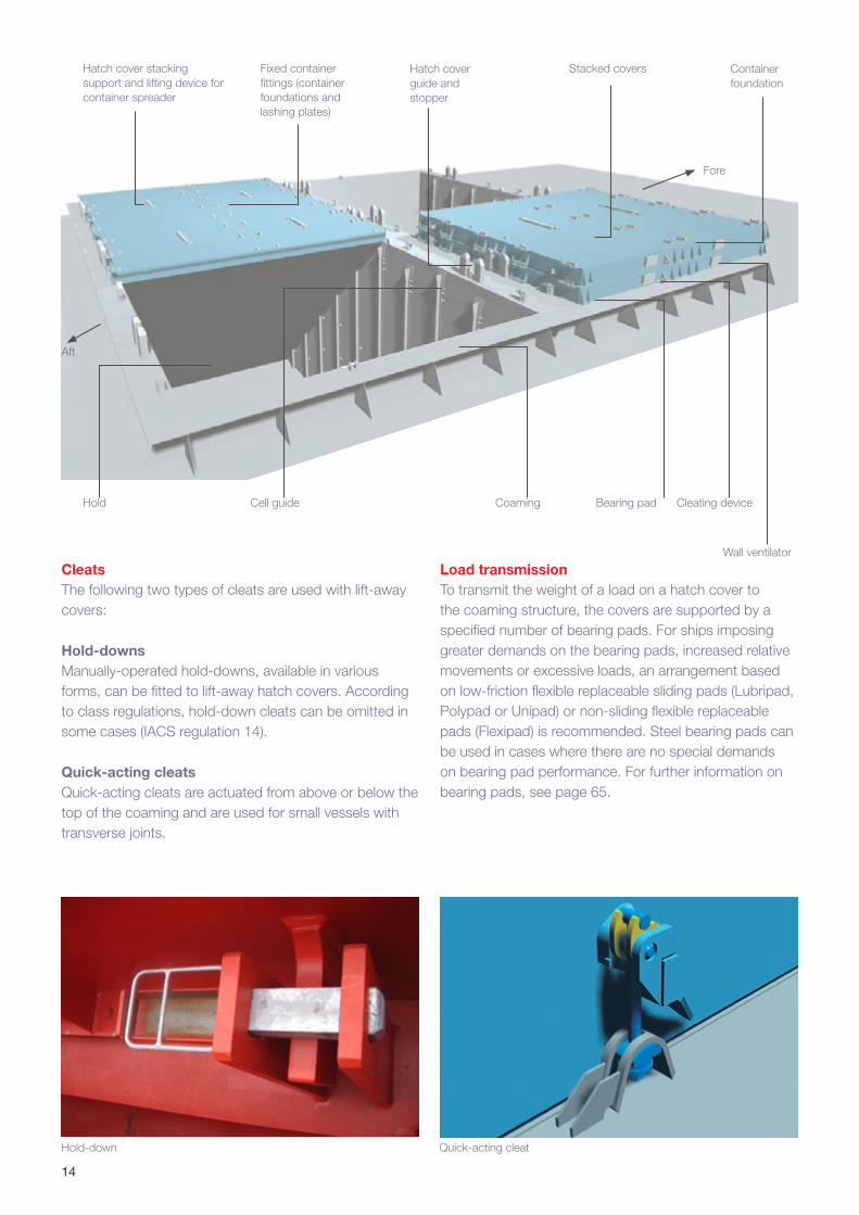
Hatch cover stacking support and lifting device for container spreader
Fixed container fittings (container foundations and lashing plates)
Hatch cover guide and stopper
Cell guideHold
Container foundation
Stacked covers
Fore
Aft
Bearing pad
Hold-down Quick-acting cleat
CleatsThe following two types of cleats are used with lift-away covers:
Hold-downsManually-operated hold-downs, available in various forms, can be fitted to lift-away hatch covers. According to class regulations, hold-down cleats can be omitted in some cases (IACS regulation 14).
Quick-acting cleatsQuick-acting cleats are actuated from above or below the top of the coaming and are used for small vessels with transverse joints.
Wall ventilator
Coaming Cleating device
Load transmissionTo transmit the weight of a load on a hatch cover to the coaming structure, the covers are supported by a specified number of bearing pads. For ships imposing greater demands on the bearing pads, increased relative movements or excessive loads, an arrangement based on low-friction flexible replaceable sliding pads (Lubripad, Polypad or Unipad) or non-sliding flexible replaceable pads (Flexipad) is recommended. Steel bearing pads can be used in cases where there are no special demands on bearing pad performance. For further information on bearing pads, see page 65.
15
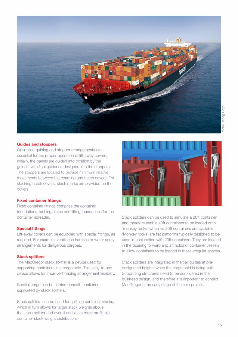
Guides and stoppersOptimised guiding and stopper arrangements are essential for the proper operation of lift-away covers. Initially, the panels are guided into position by the guides, with final guidance designed into the stoppers. The stoppers are located to provide minimum relative movements between the coaming and hatch covers. For stacking hatch covers, stack marks are provided on the covers.
Fixed container fittingsFixed container fittings comprise the container foundations, lashing plates and lifting foundations for the container spreader.
Special fittingsLift-away covers can be equipped with special fittings, as required. For example, ventilation hatches or water spray arrangements for dangerous cargoes.
Stack splittersThe MacGregor stack splitter is a device used for supporting containers in a cargo hold. This easy-to-use device allows for improved loading arrangement flexibility.
Special cargo can be carried beneath containers supported by stack splitters.
Stack splitters can be used for splitting container stacks, which in turn allows for larger stack weights above the stack splitter and overall enables a more profitable container stack weight distribution.
Pho
to: H
apag
-Llo
yd
Stack splitters can be used to simulate a 20ft container and therefore enable 40ft containers to be loaded onto ‘monkey rocks’ when no 20ft containers are available. ‘Monkey rocks’ are flat platforms typically designed to be used in conjunction with 20ft containers. They are located in the tapering forward and aft holds of container vessels to allow containers to be loaded in these irregular spaces.
Stack splitters are integrated in the cell guides at pre-designated heights when the cargo hold is being built. Supporting structures need to be considered in the bulkhead design, and therefore it is important to contact MacGregor at an early stage of the ship project.
16
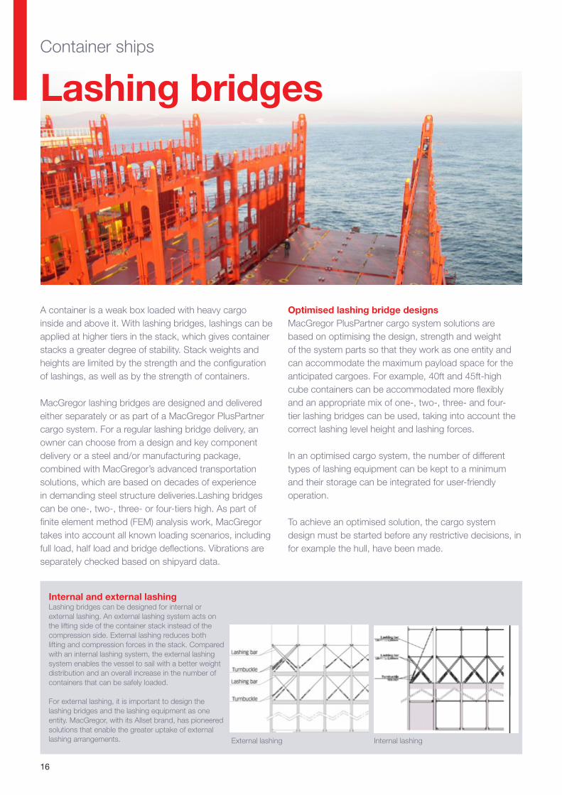
A container is a weak box loaded with heavy cargo inside and above it. With lashing bridges, lashings can be applied at higher tiers in the stack, which gives container stacks a greater degree of stability. Stack weights and heights are limited by the strength and the configuration of lashings, as well as by the strength of containers.
MacGregor lashing bridges are designed and delivered either separately or as part of a MacGregor PlusPartner cargo system. For a regular lashing bridge delivery, an owner can choose from a design and key component delivery or a steel and/or manufacturing package, combined with MacGregor’s advanced transportation solutions, which are based on decades of experience in demanding steel structure deliveries.Lashing bridges can be one-, two-, three- or four-tiers high. As part of finite element method (FEM) analysis work, MacGregor takes into account all known loading scenarios, including full load, half load and bridge deflections. Vibrations are separately checked based on shipyard data.
Lashing bridges
Optimised lashing bridge designsMacGregor PlusPartner cargo system solutions are based on optimising the design, strength and weight of the system parts so that they work as one entity and can accommodate the maximum payload space for the anticipated cargoes. For example, 40ft and 45ft-high cube containers can be accommodated more flexibly and an appropriate mix of one-, two-, three- and four-tier lashing bridges can be used, taking into account the correct lashing level height and lashing forces.
In an optimised cargo system, the number of different types of lashing equipment can be kept to a minimum and their storage can be integrated for user-friendly operation.
To achieve an optimised solution, the cargo system design must be started before any restrictive decisions, in for example the hull, have been made.
Internal and external lashingLashing bridges can be designed for internal or external lashing. An external lashing system acts on the lifting side of the container stack instead of the compression side. External lashing reduces both lifting and compression forces in the stack. Compared with an internal lashing system, the external lashing system enables the vessel to sail with a better weight distribution and an overall increase in the number of containers that can be safely loaded.
For external lashing, it is important to design the lashing bridges and the lashing equipment as one entity. MacGregor, with its Allset brand, has pioneered solutions that enable the greater uptake of external lashing arrangements.
Container ships
External lashing Internal lashing

17
All parts of the cargo system as an optimised packageA container ship’s cargo system consists of hatch covers, lashing bridges, container stanchions, deck cell guides, loose and fixed container fittings on deck and in the holds, and the cell guide system in the hold.
MacGregor is unique as the only supplier who can design and deliver all these products as an optimised package, making sure that they work in unison to maximise a ship’s payload capacity and earnings.
The system design starts in close cooperation with the customer by creating a full picture of the ship’s cargo profile and defining effective lashing patterns. Crucial information like weight distribution calculations and the comparison of total costs for different container securing systems helps to find the best fit for each ship. Also a container distribution plan based on the cargo mix can be produced.
MacGregor begins by defining the lashing arrangement, the scope of loose container fittings and the lashing lengths and by creating a preliminary container securing arrangement. For this, the ship’s details and specific information such as anticipated container heights and sizes, stack loads, preferred type of lashing system and lashing bridge particulars are required.
When the container securing system details have been decided, MacGregor finalises the container securing arrangement (CSA), which can be tested and verified efficiently by a full-size mock-up test. The CSA, once
Product catalogue
Container securing systems
10662_macgregor_brochure_template_a4_4pages_040714.indd 1 25/01/2016 12:46:09
approved by the customer, is then reviewed in a design review meeting and sent to the classification society for its approval.
When classification society approval has been received, the CSA forms a part of the cargo securing manual (CSM), which again is sent to the classification society for approval. At the same time, MacGregor’s designers finalise all related documentation and software.
As a result of the container securing system design process, the customer receives the approved cargo securing manual and all completed documentation, while at the same time the hardware is delivered to the shipyard.
All system details are documented in the product data management system for easy reference at a later date.
For detailed information, please see the Container securing systems product catalogue: http://issuu.com/cargotec/docs/container_securing_systems_product_
18
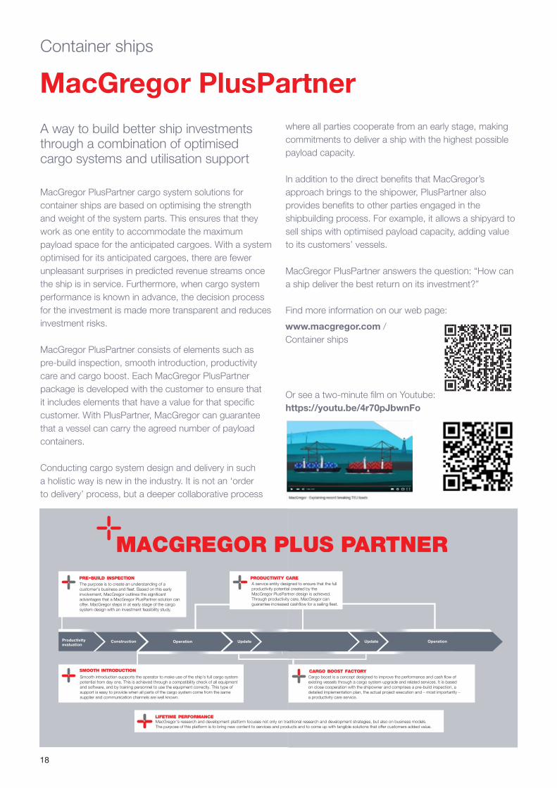
MacGregor PlusPartner cargo system solutions for container ships are based on optimising the strength and weight of the system parts. This ensures that they work as one entity to accommodate the maximum payload space for the anticipated cargoes. With a system optimised for its anticipated cargoes, there are fewer unpleasant surprises in predicted revenue streams once the ship is in service. Furthermore, when cargo system performance is known in advance, the decision process for the investment is made more transparent and reduces investment risks.
MacGregor PlusPartner consists of elements such as pre-build inspection, smooth introduction, productivity care and cargo boost. Each MacGregor PlusPartner package is developed with the customer to ensure that it includes elements that have a value for that specific customer. With PlusPartner, MacGregor can guarantee that a vessel can carry the agreed number of payload containers.
Conducting cargo system design and delivery in such a holistic way is new in the industry. It is not an ‘order to delivery’ process, but a deeper collaborative process
A way to build better ship investments through a combination of optimised cargo systems and utilisation support
Update OperationOperation
Cargo boost is a concept designed to improve the performance and cash flow of existing vessels through a cargo system upgrade and related services. It is based on close cooperation with the shipowner and comprises a pre-build inspection, a detailed implementation plan, the actual project execution and – most importantly – a productivity care service.
UpdateOperationConstructionProductivityevaluation
The purpose is to create an understanding of a customer's business and fleet. Based on this early involvement, MacGregor outlines the significant advantages that a MacGregor PlusPartner solution can offer. MacGregor steps in at early stage of the cargo system design with an investment feasibility study.
A service entity designed to ensure that the full productivity potential created by the MacGregor PlusPartner design is achieved. Through productivity care, MacGregor can guarantee increased cashflow for a sailing fleet.
Smooth introduction supports the operator to make use of the ship's full cargo system potential from day one. This is achieved through a compatibility check of all equipment and software, and by training personnel to use the equipment correctly. This type of support is easy to provide when all parts of the cargo system come from the same supplier and communication channels are well known.
MacGregor's research and development platform focuses not only on traditional research and development strategies, but also on business models. The purpose of this platform is to bring new content to services and products and to come up with tangible solutions that offer customers added value.
where all parties cooperate from an early stage, making commitments to deliver a ship with the highest possible payload capacity.
In addition to the direct benefits that MacGregor’s approach brings to the shipower, PlusPartner also provides benefits to other parties engaged in the shipbuilding process. For example, it allows a shipyard to sell ships with optimised payload capacity, adding value to its customers’ vessels.
MacGregor PlusPartner answers the question: “How can a ship deliver the best return on its investment?”
MacGregor PlusPartnerContainer ships
Find more information on our web page:
www.macgregor.com / Container ships
Or see a two-minute film on Youtube: https://youtu.be/4r70pJbwnFo
19
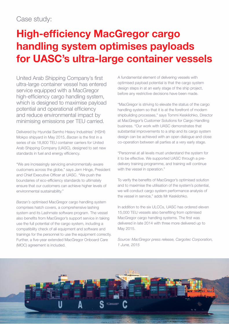
High-efficiency MacGregor cargo handling system optimises payloads for UASC’s ultra-large container vessels
Delivered by Hyundai Samho Heavy Industries’ (HSHI) Mokpo shipyard in May 2015, Barzan is the first in a series of six 18,800 TEU container carriers for United Arab Shipping Company (UASC), designed to set new standards in fuel and energy efficiency.
“We are increasingly servicing environmentally-aware customers across the globe,” says Jørn Hinge, President and Chief Executive Officer at UASC. “We push the boundaries of eco-efficiency standards to ultimately ensure that our customers can achieve higher levels of environmental sustainability.”
Barzan’s optimised MacGregor cargo handling system comprises hatch covers, a comprehensive lashing system and its Lashmate software program. The vessel also benefits from MacGregor’s support service in taking use the full potential of the cargo system, including a compatibility check of all equipment and software and trainings for the personnel to use the equipment correctly. Further, a five-year extended MacGregor Onboard Care (MOC) agreement is included.
A fundamental element of delivering vessels with optimised payload potential is that the cargo system design steps in at an early stage of the ship project, before any restrictive decisions have been made.
“MacGregor is striving to elevate the status of the cargo handling system so that it is at the forefront of modern shipbuilding processes,” says Tommi Keskilohko, Director at MacGregor’s Customer Solutions for Cargo Handling business. “Our work with UASC demonstrates that substantial improvements to a ship and its cargo system design can be achieved with an open dialogue and close co-operation between all parties at a very early stage.
“Personnel at all levels must understand the system for it to be effective. We supported UASC through a pre-delivery training programme, and training will continue with the vessel in operation.”
To verify the benefits of MacGregor’s optimised solution and to maximise the utilisation of the system’s potential, we will conduct cargo system performance analysis of the vessel in service,” adds Mr Keskilohko.
In addition to the six ULCCs, UASC has ordered eleven 15,000 TEU vessels also benefiting from optimised MacGregor cargo handling systems. The first was delivered in late 2014 with three more delivered up to May 2015.
Source: MacGregor press release, Cargotec Corporation, 1 June, 2015
United Arab Shipping Company’s first ultra-large container vessel has entered service equipped with a MacGregor high-efficiency cargo handling system, which is designed to maximise payload potential and operational efficiency and reduce environmental impact by minimising emissions per TEU carried.
Case study:
20
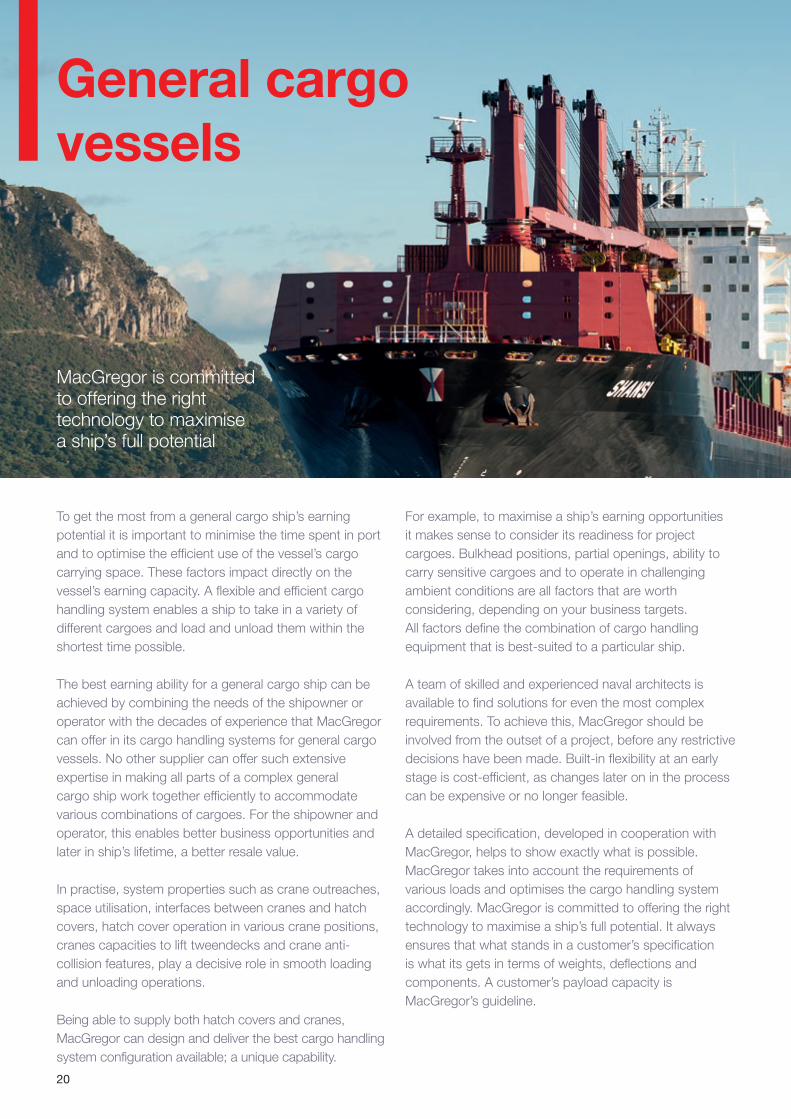
General cargo vessels
MacGregor is committed to offering the right technology to maximise a ship’s full potential
To get the most from a general cargo ship’s earning potential it is important to minimise the time spent in port and to optimise the efficient use of the vessel’s cargo carrying space. These factors impact directly on the vessel’s earning capacity. A flexible and efficient cargo handling system enables a ship to take in a variety of different cargoes and load and unload them within the shortest time possible.
The best earning ability for a general cargo ship can be achieved by combining the needs of the shipowner or operator with the decades of experience that MacGregor can offer in its cargo handling systems for general cargo vessels. No other supplier can offer such extensive expertise in making all parts of a complex general cargo ship work together efficiently to accommodate various combinations of cargoes. For the shipowner and operator, this enables better business opportunities and later in ship’s lifetime, a better resale value.
In practise, system properties such as crane outreaches, space utilisation, interfaces between cranes and hatch covers, hatch cover operation in various crane positions, cranes capacities to lift tweendecks and crane anti-collision features, play a decisive role in smooth loading and unloading operations.
Being able to supply both hatch covers and cranes, MacGregor can design and deliver the best cargo handling system configuration available; a unique capability.
For example, to maximise a ship’s earning opportunities it makes sense to consider its readiness for project cargoes. Bulkhead positions, partial openings, ability to carry sensitive cargoes and to operate in challenging ambient conditions are all factors that are worth considering, depending on your business targets. All factors define the combination of cargo handling equipment that is best-suited to a particular ship.
A team of skilled and experienced naval architects is available to find solutions for even the most complex requirements. To achieve this, MacGregor should be involved from the outset of a project, before any restrictive decisions have been made. Built-in flexibility at an early stage is cost-efficient, as changes later on in the process can be expensive or no longer feasible.
A detailed specification, developed in cooperation with MacGregor, helps to show exactly what is possible. MacGregor takes into account the requirements of various loads and optimises the cargo handling system accordingly. MacGregor is committed to offering the right technology to maximise a ship’s full potential. It always ensures that what stands in a customer’s specification is what its gets in terms of weights, deflections and components. A customer’s payload capacity is MacGregor’s guideline.
21
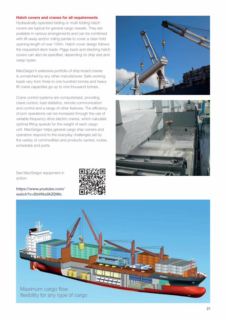
Hatch covers and cranes for all requirementsHydraulically-operated folding or multi-folding hatch covers are typical for general cargo vessels. They are available in various arrangements and can be combined with lift-away and/or rolling panels to cover a clear hold opening length of over 100m. Hatch cover design follows the requested deck loads. Piggy-back and stacking hatch covers can also be specified, depending on ship size and cargo types.
MacGregor’s extensive portfolio of ship-board cranes is unmatched by any other manufacturer. Safe working loads vary from three to one hundred tonnes and heavy lift crane capacities go up to one thousand tonnes.
Crane control systems are computerised, providing crane control, load statistics, remote communication and control and a range of other features. The efficiency of port operations can be increased through the use of variable frequency drive electric cranes, which calculate optimal lifting speeds for the weight of each cargo unit. MacGregor helps general cargo ship owners and operators respond to the everyday challenges set by the variety of commodities and products carried, routes, schedules and ports.
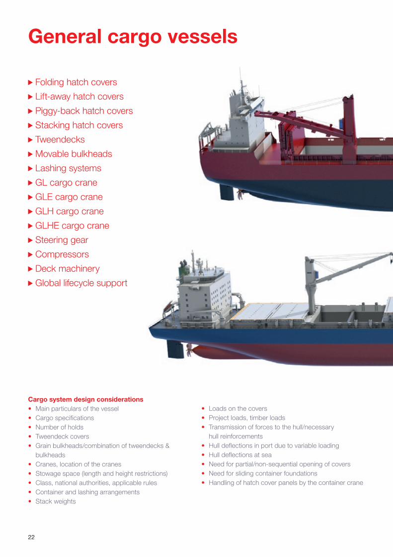
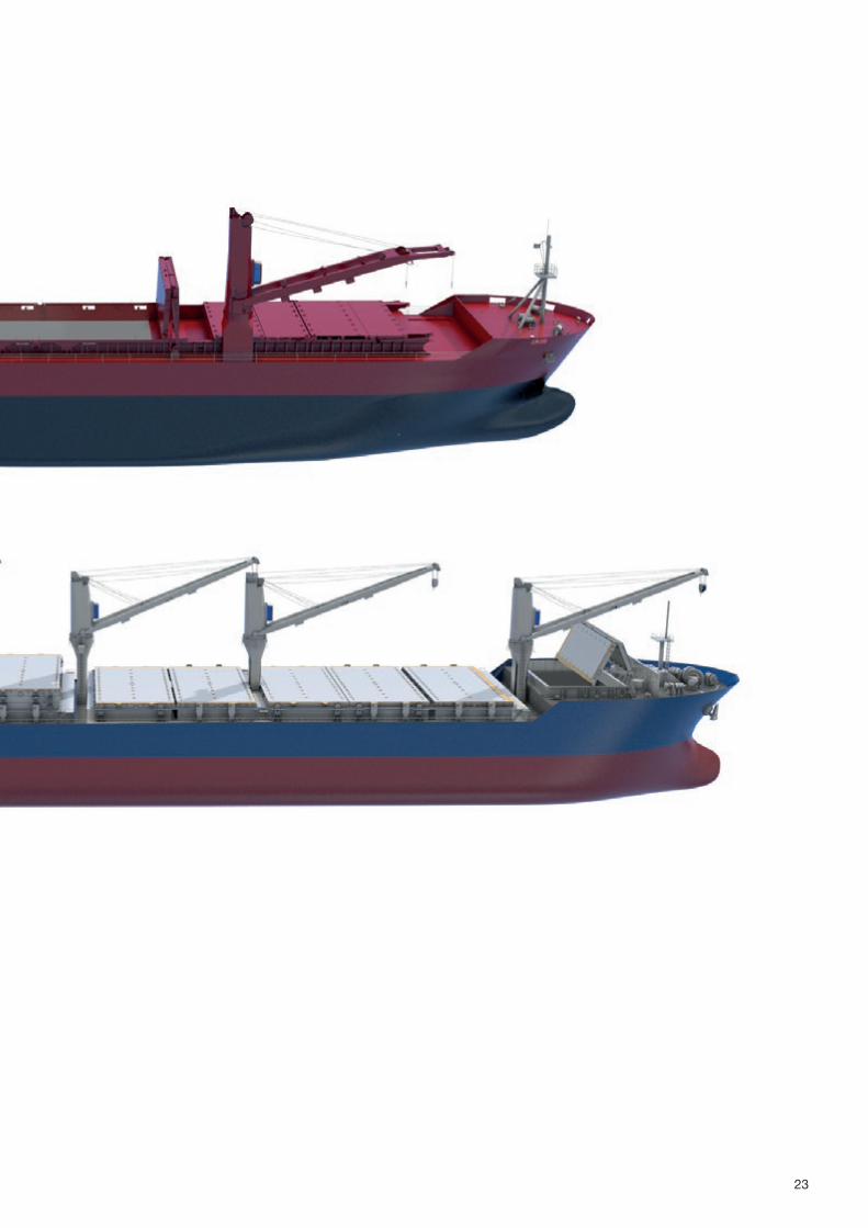
Maximum cargo flow flexibility for any type of cargo
See MacGregor equipment in action:
https://www.youtube.com/watch?v=DbVNu5KZDMc
22
Folding hatch covers
Lift-away hatch covers
Piggy-back hatch covers
Stacking hatch covers
Tweendecks
Movable bulkheads
Lashing systems
GL cargo crane
GLE cargo crane
GLH cargo crane
GLHE cargo crane
Steering gear
Compressors
Deck machinery
Global lifecycle support
General cargo vessels
Cargo system design considerations• Main particulars of the vessel• Cargo specifications• Number of holds• Tweendeck covers• Grain bulkheads/combination of tweendecks &
bulkheads• Cranes, location of the cranes• Stowage space (length and height restrictions)• Class, national authorities, applicable rules• Container and lashing arrangements• Stack weights
• Loads on the covers• Project loads, timber loads• Transmission of forces to the hull/necessary
hull reinforcements• Hull deflections in port due to variable loading• Hull deflections at sea• Need for partial/non-sequential opening of covers• Need for sliding container foundations• Handling of hatch cover panels by the container crane
23
24
Innovation, reliability and cost-efficiency are keys to successTwo new 20,000 dwt multipurpose vessels for Rickmers Group have been designed to maximise every aspect of operational efficiency; their MacGregor systems will play an essential role
At the end of 2012, Rickmers would take over a contract for the construction of two 20,000 dwt multipurpose vessels to a design that would reflect market demands for effcient, flexible and reliable vessels. Construction of the new-buildings is well underway at Hudong-Zhonghua Shipbuilding, in China, with delivery planned for early 2015.
“Vessels of this type have traditionally had very standard designs,” says Dr Georg Eljardt, Director of Maritime Technology, Rickmers Group. “We took over the newbuilding project under the condition that we could change many elements of the design to ensure the highest degrees of effciency on board.
The significantly improved technical specifications will lead to a substantial reduction in fuel consumption. An optimised hull form together with a high effciency propeller and rudder will enable the new ships to achieve an operating speed of 16.5 knots while using considerably less power than comparable vessels and being optimised for slower speeds operating down to 10 percent MCR.
Designed for flexibility The new vessels reflect Rickmers’ commitment to efficiency and safety. “For multipurpose vessels the market is tough, with a lot of competition,” says Dr Eljardt, “so it is crucial that the vessel is able to take just about any type of cargo and handle it very time- and fuel-efficiently.”
Cargo profile was a key consideration when designing the vessels. “We investigated different cargo profiles, drafs and hull forms; all with a view to delivering maximum market access. The vessels now have one large, long cargo hold, which can be subdivided to accommodate a wide range and combination of bulk, break bulk, heavy
lift and project cargo. The MacGregor system we have chosen offers a great deal of flexibility in comparison to the previous traditional design,” he notes.
In addition to an optimised hull form, the vessels feature further improvements with regard to the propulsion train. The whole engine room has been re-designed to accommodate a slow speed two-stroke diesel main engine. “In addition they also are the first vessels to feature an ESPAC (Energy Saving Package) propulsion
system which, through a combined design process of the propeller and rudder, unlocks otherwise lost energy-saving potential. This innovative arrangement will allow the vessels to operate very efficiently throughout the whole operating range from slow steaming to service speed. Together with the ability to take as much cargo of as many types as possible, this offers the operator much more time to react in this volatile market.
“This type of ship spends proportionally more time in port than other types of trading vessel,” explains Dr Eljardt. “If the vessel is in demand, anything that can be done to speed up operations in port is beneficial. On the other hand, if there is less work, these vessels can run at slower speeds, but very efficiently. They really are forerunners in the market.”
New and proven technologiesThe vessels feature new and service-proven MacGregor technologies. “We wanted a supplier that offered the best quality engineering solution, with the highest quality fabrication processes,” says Dr Eljardt. “The reliability of the cargo handling system, its function and efficiency are essential elements of these vessels.
“We wanted tailor-made solutions to ensure a good quality package of equipment that will deliver the most
“The MacGregor system offers a great deal of fexibility in comparison with a traditional design”
Dr-Ing Georg Eljardt
Case study:
25
efficient vessels possible. To achieve this we needed to plan at the earliest possible stage.
“Early involvement of cargo handling specialists is crucial for the successful end result of any project. This will define the final ship. This early involvement also reduces changes later in the build processes. The clearer the design, and the fewer the changes during the build process, the more cost-efficient the build will be.”
MacGregor’s scope of supply Design and key components for: • Multi-folding hatch covers • Rolling hatch covers • Lift-away hatch cover panels• Pivoting grommet hatch cover• In-hold tweendeck lift-away hatch covers with
consoles, and with respective console pocket design, at four levels
• Panels are designed for heavy loads: weather deck 5 tonnes/m2; midships 8 tonnes/m2; maximum payload 1,250 tonnes
Hardware:• Bulkhead sealing gear• Tweendeck consoles and pocket covers• Soft-start units for hydraulic system motors • Wireless remote control of operating valves for hatch
covers nos 1 & 2• Hatlapa steering gear
The Rickmers Group has the highest expectations of MacGregor’s equipment, based on a long history of successful deliveries. “We know pretty well what we can expect. Our previous experience with MacGregor equipment was definitely a deciding factor when choosing the equipment for these vessels. When considering future vessels, MacGregor would definitely be a supplier that we would look at, and we would also consider MacGregor’s electric cranes.
“Besides energy efficiency, good service and the availability of parts are also crucial factors,” he notes. “For this vital equipment we need a strong partner. We aim to offer our charter clients reliable vessels and the best service possible; we cannot jeopardise this. Therefore choosing a partner with a strong service capability, who helps us achieve this reliability, is extremely important to us.”
Success in volatile marketsIn terms of significant developments in general cargo shipping trade over the next few years, Dr Eljardt believes that it will continue to be tough. “The particular markets for multipurpose vessels are volatile and volumes are reduced. This volatility, coupled with significant overcapacity, means that it is crucial to have a ship that best suits the market and maximises every aspect of operational efficiency. Innovation, reliability and cost-efficiency are keys to this success and cargo handling systems play an essential role in this equation.”
Source: MacGregor News autumn 2013
26
Folding hatch covers
It is important for all cargo ships that weather deck and cargo space layouts are designed with the highest possible level of cargo handling efficiency in mind. This allows for fast and safe loading. MacGregor makes sure that the arrangement of hatch covers, sealings, support pads and locators are optimised to deliver uncompromised weathertightness to protect the cargo and to ensure the safety of the ship.
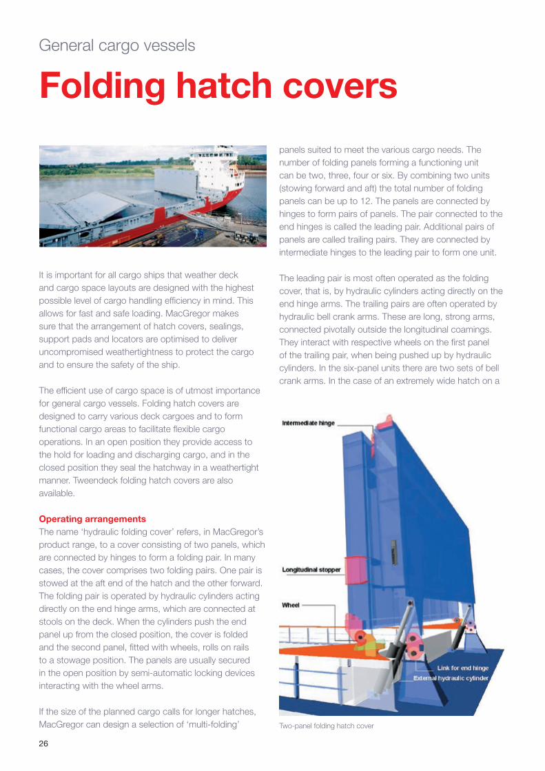
The efficient use of cargo space is of utmost importance for general cargo vessels. Folding hatch covers are designed to carry various deck cargoes and to form functional cargo areas to facilitate flexible cargo operations. In an open position they provide access to the hold for loading and discharging cargo, and in the closed position they seal the hatchway in a weathertight manner. Tweendeck folding hatch covers are also available.
Operating arrangementsThe name ‘hydraulic folding cover’ refers, in MacGregor’s product range, to a cover consisting of two panels, which are connected by hinges to form a folding pair. In many cases, the cover comprises two folding pairs. One pair is stowed at the aft end of the hatch and the other forward. The folding pair is operated by hydraulic cylinders acting directly on the end hinge arms, which are connected at stools on the deck. When the cylinders push the end panel up from the closed position, the cover is folded and the second panel, fitted with wheels, rolls on rails to a stowage position. The panels are usually secured in the open position by semi-automatic locking devices interacting with the wheel arms.
If the size of the planned cargo calls for longer hatches, MacGregor can design a selection of ‘multi-folding’ Two-panel folding hatch cover
General cargo vessels
panels suited to meet the various cargo needs. The number of folding panels forming a functioning unit can be two, three, four or six. By combining two units (stowing forward and aft) the total number of folding panels can be up to 12. The panels are connected by hinges to form pairs of panels. The pair connected to the end hinges is called the leading pair. Additional pairs of panels are called trailing pairs. They are connected by intermediate hinges to the leading pair to form one unit.
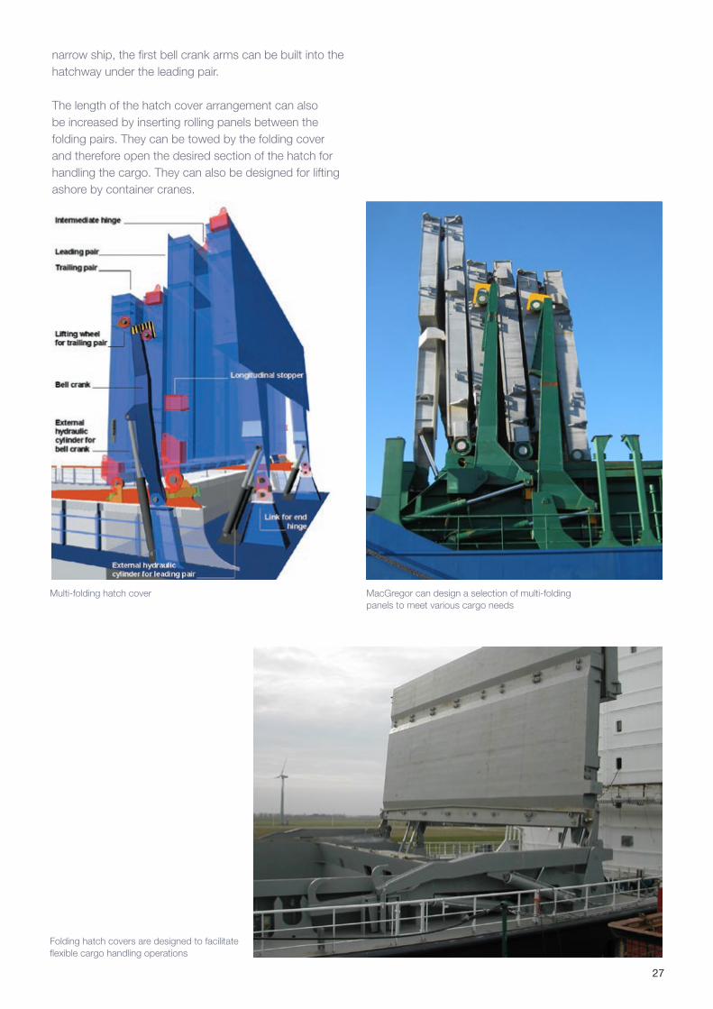
The leading pair is most often operated as the folding cover, that is, by hydraulic cylinders acting directly on the end hinge arms. The trailing pairs are often operated by hydraulic bell crank arms. These are long, strong arms, connected pivotally outside the longitudinal coamings. They interact with respective wheels on the first panel of the trailing pair, when being pushed up by hydraulic cylinders. In the six-panel units there are two sets of bell crank arms. In the case of an extremely wide hatch on a
27
narrow ship, the first bell crank arms can be built into the hatchway under the leading pair.
The length of the hatch cover arrangement can also be increased by inserting rolling panels between the folding pairs. They can be towed by the folding cover and therefore open the desired section of the hatch for handling the cargo. They can also be designed for lifting ashore by container cranes.
Multi-folding hatch cover
Folding hatch covers are designed to facilitate flexible cargo handling operations
MacGregor can design a selection of multi-folding panels to meet various cargo needs
28
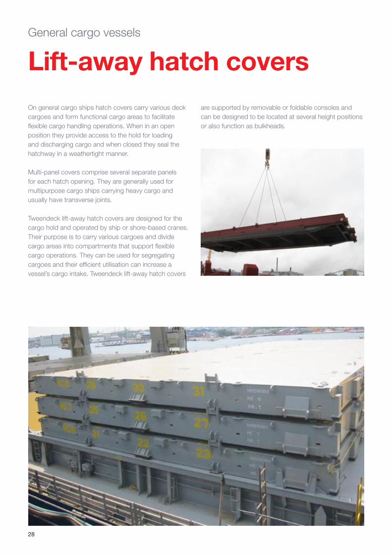
On general cargo ships hatch covers carry various deck cargoes and form functional cargo areas to facilitate flexible cargo handling operations. When in an open position they provide access to the hold for loading and discharging cargo and when closed they seal the hatchway in a weathertight manner.
Multi-panel covers comprise several separate panels for each hatch opening. They are generally used for multipurpose cargo ships carrying heavy cargo and usually have transverse joints.
Tweendeck lift-away hatch covers are designed for the cargo hold and operated by ship or shore-based cranes. Their purpose is to carry various cargoes and divide cargo areas into compartments that support flexible cargo operations. They can be used for segregating cargoes and their efficient utilisation can increase a vessel’s cargo intake. Tweendeck lift-away hatch covers
Lift-away hatch coversGeneral cargo vessels
are supported by removable or foldable consoles and can be designed to be located at several height positions or also function as bulkheads.
29
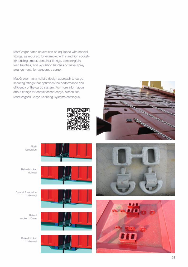
Flush foundation
Raised socket dovetail
Dovetail foundation in channel
Raised socket 110mm
Raised socket in channel
MacGregor hatch covers can be equipped with special fittings, as required: for example, with stanchion sockets for loading timber, container fittings, cement/grain feed hatches, and ventilation hatches or water spray arrangements for dangerous cargo.
MacGregor has a holistic design approach to cargo securing fittings that optimises the performance and efficiency of the cargo system. For more information about fittings for containerised cargo, please see
MacGregor’s Cargo Securing Systems catalogue.
30
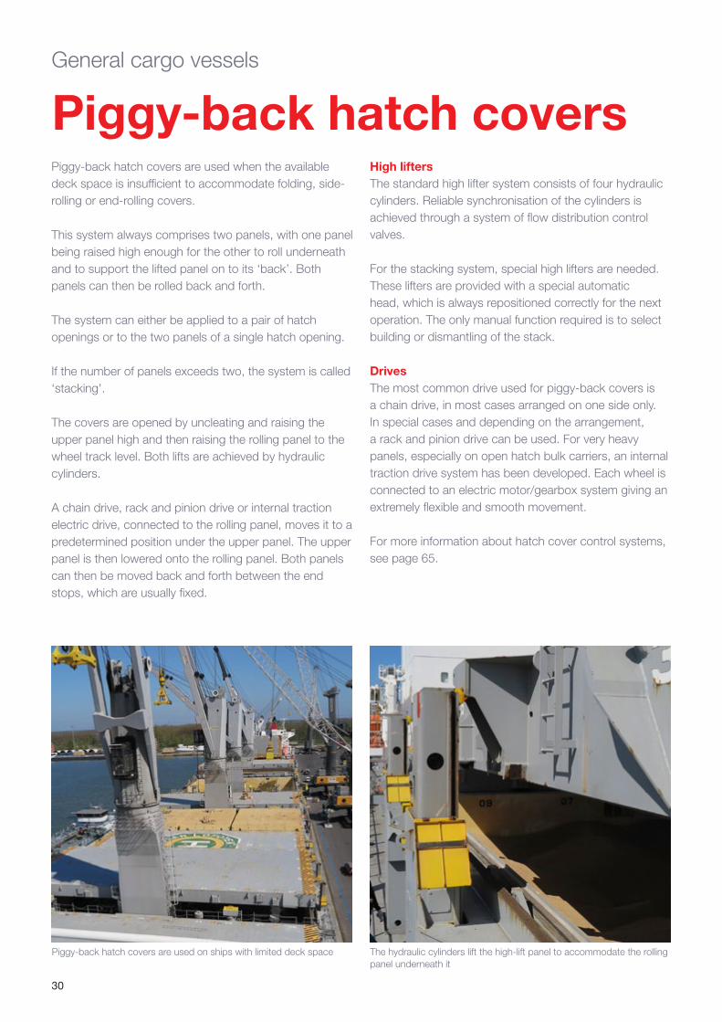
Piggy-back hatch covers are used on ships with limited deck space The hydraulic cylinders lift the high-lift panel to accommodate the rolling panel underneath it
Piggy-back hatch coversPiggy-back hatch covers are used when the available deck space is insufficient to accommodate folding, side-rolling or end-rolling covers.
This system always comprises two panels, with one panel being raised high enough for the other to roll underneath and to support the lifted panel on to its ‘back’. Both panels can then be rolled back and forth.
The system can either be applied to a pair of hatch openings or to the two panels of a single hatch opening.
If the number of panels exceeds two, the system is called ‘stacking'.
The covers are opened by uncleating and raising the upper panel high and then raising the rolling panel to the wheel track level. Both lifts are achieved by hydraulic cylinders.
A chain drive, rack and pinion drive or internal traction electric drive, connected to the rolling panel, moves it to a predetermined position under the upper panel. The upper panel is then lowered onto the rolling panel. Both panels can then be moved back and forth between the end stops, which are usually fixed.
General cargo vessels
High liftersThe standard high lifter system consists of four hydraulic cylinders. Reliable synchronisation of the cylinders is achieved through a system of flow distribution control valves.
For the stacking system, special high lifters are needed. These lifters are provided with a special automatic head, which is always repositioned correctly for the next operation. The only manual function required is to select building or dismantling of the stack.
DrivesThe most common drive used for piggy-back covers is a chain drive, in most cases arranged on one side only. In special cases and depending on the arrangement, a rack and pinion drive can be used. For very heavy panels, especially on open hatch bulk carriers, an internal traction drive system has been developed. Each wheel is connected to an electric motor/gearbox system giving an extremely flexible and smooth movement.
For more information about hatch cover control systems, see page 65.
31
Stacking hatch covers
Pivoting hatch covers
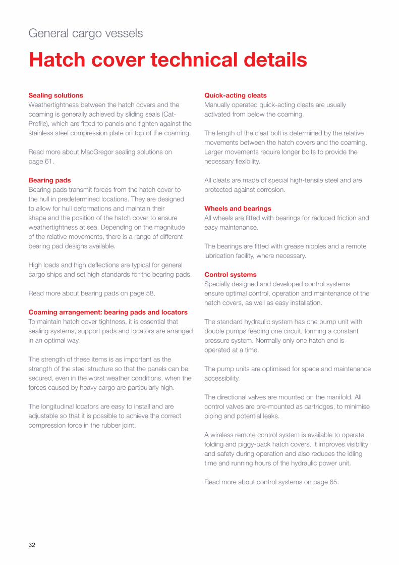
Stacking hatch covers for weather decks are usually all hydraulic in operation and the panels move into stowage or closure positions in a specific sequence.
A set will comprise several panels – each of which is fitted with a towing device that can be connected to move the panels to and from a stacking position by a continuous chain drive mechanism.
The chain-driven stacking hatch cover system employs the same hoisting principles as the piggy-back system.
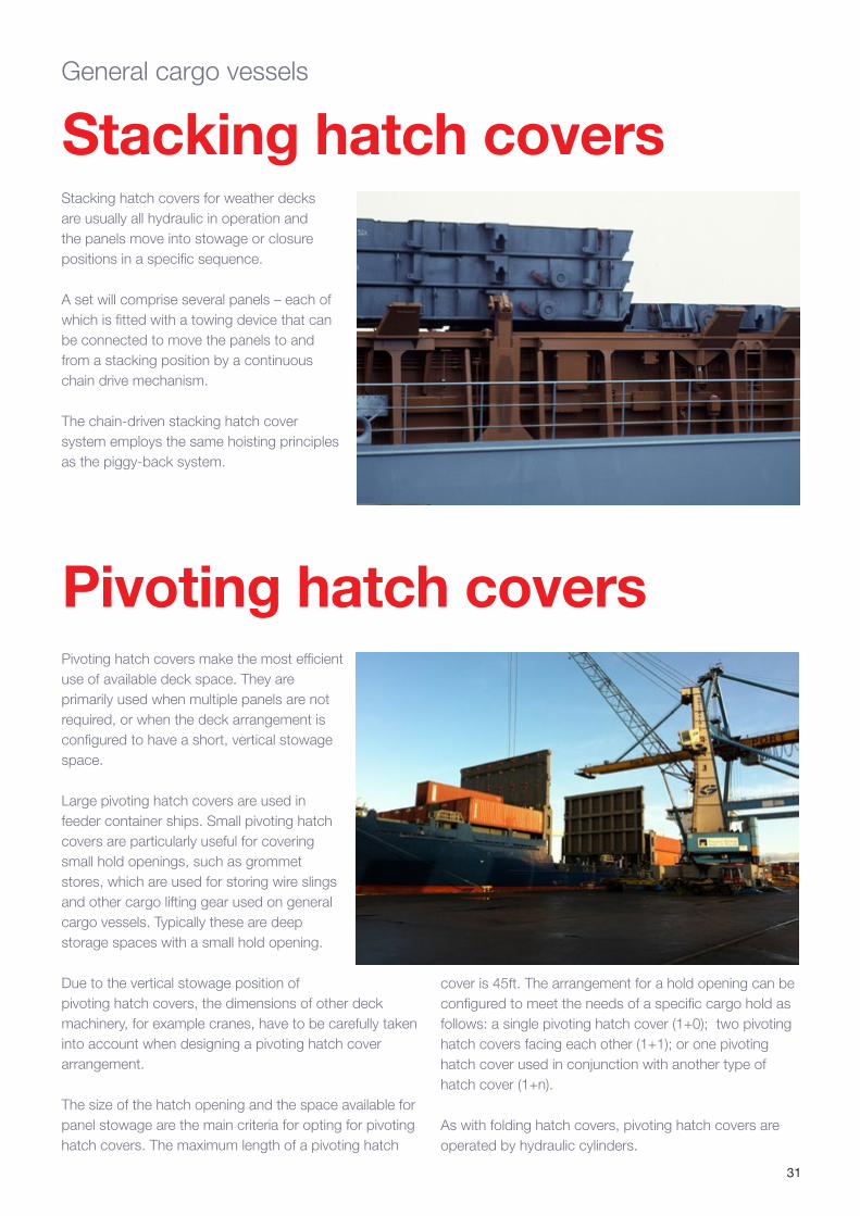
Pivoting hatch covers make the most efficient use of available deck space. They are primarily used when multiple panels are not required, or when the deck arrangement is configured to have a short, vertical stowage space.
Large pivoting hatch covers are used in feeder container ships. Small pivoting hatch covers are particularly useful for covering small hold openings, such as grommet stores, which are used for storing wire slings and other cargo lifting gear used on general cargo vessels. Typically these are deep storage spaces with a small hold opening.
Due to the vertical stowage position of pivoting hatch covers, the dimensions of other deck machinery, for example cranes, have to be carefully taken into account when designing a pivoting hatch cover arrangement.
The size of the hatch opening and the space available for panel stowage are the main criteria for opting for pivoting hatch covers. The maximum length of a pivoting hatch
General cargo vessels
cover is 45ft. The arrangement for a hold opening can be configured to meet the needs of a specific cargo hold as follows: a single pivoting hatch cover (1+0); two pivoting hatch covers facing each other (1+1); or one pivoting hatch cover used in conjunction with another type of hatch cover (1+n).
As with folding hatch covers, pivoting hatch covers are operated by hydraulic cylinders.
32
General cargo vessels
Hatch cover technical details
Sealing solutionsWeathertightness between the hatch covers and the coaming is generally achieved by sliding seals (Cat-Profile), which are fitted to panels and tighten against the stainless steel compression plate on top of the coaming.
Read more about MacGregor sealing solutions on page 61.
Bearing pads Bearing pads transmit forces from the hatch cover to the hull in predetermined locations. They are designed to allow for hull deformations and maintain their shape and the position of the hatch cover to ensure weathertightness at sea. Depending on the magnitude of the relative movements, there is a range of different bearing pad designs available.
High loads and high deflections are typical for general cargo ships and set high standards for the bearing pads.
Read more about bearing pads on page 58.
Coaming arrangement: bearing pads and locators To maintain hatch cover tightness, it is essential that sealing systems, support pads and locators are arranged in an optimal way.
The strength of these items is as important as the strength of the steel structure so that the panels can be secured, even in the worst weather conditions, when the forces caused by heavy cargo are particularly high.
The longitudinal locators are easy to install and are adjustable so that it is possible to achieve the correct compression force in the rubber joint.
Quick-acting cleatsManually operated quick-acting cleats are usually activated from below the coaming.
The length of the cleat bolt is determined by the relative movements between the hatch covers and the coaming. Larger movements require longer bolts to provide the necessary flexibility.
All cleats are made of special high-tensile steel and are protected against corrosion.
Wheels and bearingsAll wheels are fitted with bearings for reduced friction and easy maintenance.
The bearings are fitted with grease nipples and a remote lubrication facility, where necessary.
Control systemsSpecially designed and developed control systems ensure optimal control, operation and maintenance of the hatch covers, as well as easy installation.
The standard hydraulic system has one pump unit with double pumps feeding one circuit, forming a constant pressure system. Normally only one hatch end is operated at a time.
The pump units are optimised for space and maintenance accessibility.
The directional valves are mounted on the manifold. All control valves are pre-mounted as cartridges, to minimise piping and potential leaks.
A wireless remote control system is available to operate folding and piggy-back hatch covers. It improves visibility and safety during operation and also reduces the idling time and running hours of the hydraulic power unit.
Read more about control systems on page 65.
33
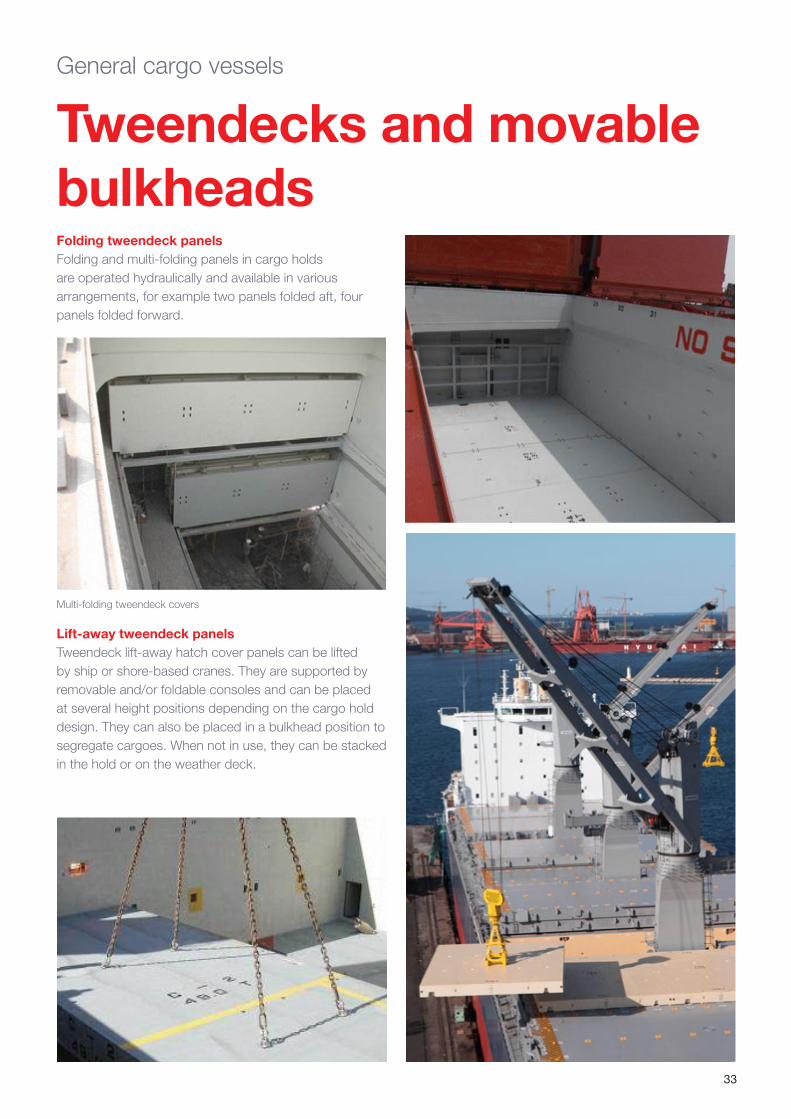
Tweendecks and movable bulkheadsFolding tweendeck panelsFolding and multi-folding panels in cargo holds are operated hydraulically and available in various arrangements, for example two panels folded aft, four panels folded forward.
Multi-folding tweendeck covers
Lift-away tweendeck panelsTweendeck lift-away hatch cover panels can be lifted by ship or shore-based cranes. They are supported by removable and/or foldable consoles and can be placed at several height positions depending on the cargo hold design. They can also be placed in a bulkhead position to segregate cargoes. When not in use, they can be stacked in the hold or on the weather deck.
General cargo vessels
34
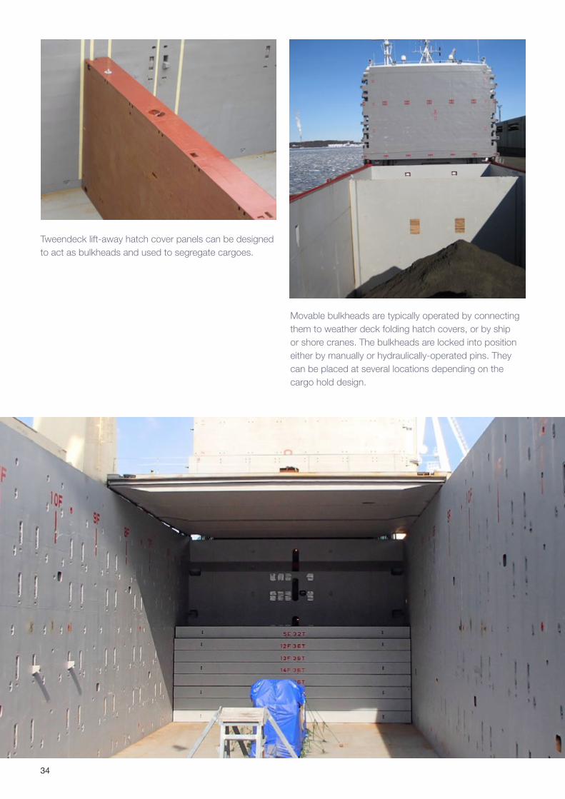
Tweendeck lift-away hatch cover panels can be designed to act as bulkheads and used to segregate cargoes.
Movable bulkheads are typically operated by connecting them to weather deck folding hatch covers, or by ship or shore cranes. The bulkheads are locked into position either by manually or hydraulically-operated pins. They can be placed at several locations depending on the cargo hold design.
35
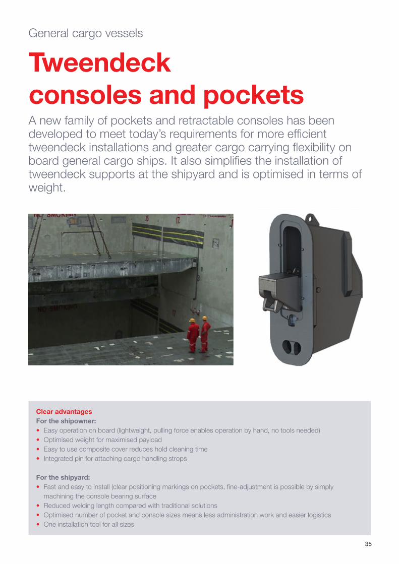
Tweendeck consoles and pocketsA new family of pockets and retractable consoles has been developed to meet today’s requirements for more efficient tweendeck installations and greater cargo carrying flexibility on board general cargo ships. It also simplifies the installation of tweendeck supports at the shipyard and is optimised in terms of weight.
Clear advantagesFor the shipowner:• Easy operation on board (lightweight, pulling force enables operation by hand, no tools needed)• Optimised weight for maximised payload• Easy to use composite cover reduces hold cleaning time• Integrated pin for attaching cargo handling strops
For the shipyard:• Fast and easy to install (clear positioning markings on pockets, fine-adjustment is possible by simply
machining the console bearing surface• Reduced welding length compared with traditional solutions• Optimised number of pocket and console sizes means less administration work and easier logistics• One installation tool for all sizes
General cargo vessels
36
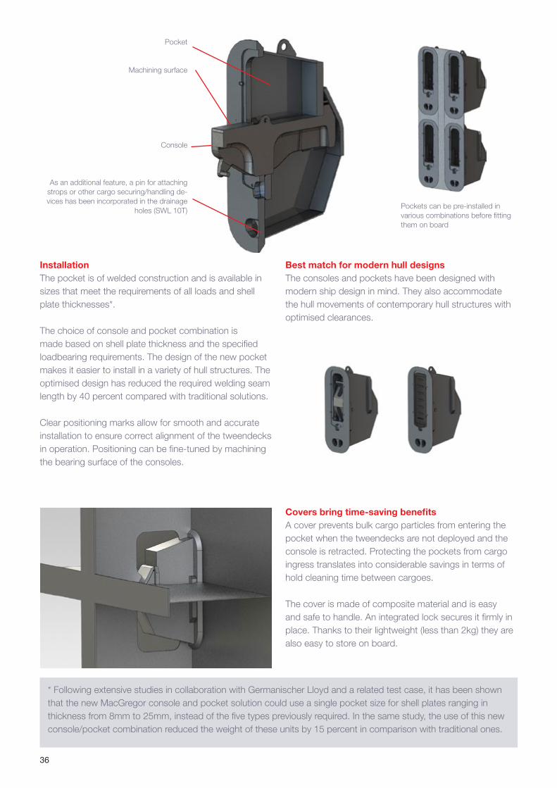
InstallationThe pocket is of welded construction and is available in sizes that meet the requirements of all loads and shell plate thicknesses*.
The choice of console and pocket combination is made based on shell plate thickness and the specified loadbearing requirements. The design of the new pocket makes it easier to install in a variety of hull structures. The optimised design has reduced the required welding seam length by 40 percent compared with traditional solutions.
Clear positioning marks allow for smooth and accurate installation to ensure correct alignment of the tweendecks in operation. Positioning can be fine-tuned by machining the bearing surface of the consoles.
Machining surface
Console
As an additional feature, a pin for attaching strops or other cargo securing/handling de-vices has been incorporated in the drainage
holes (SWL 10T)
Best match for modern hull designs The consoles and pockets have been designed with modern ship design in mind. They also accommodate the hull movements of contemporary hull structures with optimised clearances.
Pockets can be pre-installed in various combinations before fitting them on board
* Following extensive studies in collaboration with Germanischer Lloyd and a related test case, it has been shown that the new MacGregor console and pocket solution could use a single pocket size for shell plates ranging in thickness from 8mm to 25mm, instead of the five types previously required. In the same study, the use of this new console/pocket combination reduced the weight of these units by 15 percent in comparison with traditional ones.
Covers bring time-saving benefitsA cover prevents bulk cargo particles from entering the pocket when the tweendecks are not deployed and the console is retracted. Protecting the pockets from cargo ingress translates into considerable savings in terms of hold cleaning time between cargoes.
The cover is made of composite material and is easy and safe to handle. An integrated lock secures it firmly in place. Thanks to their lightweight (less than 2kg) they are also easy to store on board.
37
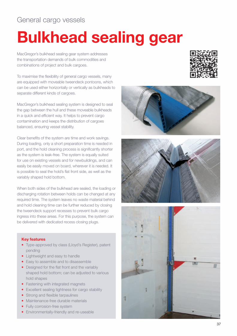
Bulkhead sealing gearMacGregor’s bulkhead sealing gear system addresses the transportation demands of bulk commodities and combinations of project and bulk cargoes.
To maximise the flexibility of general cargo vessels, many are equipped with moveable tweendeck pontoons, which can be used either horizontally or vertically as bulkheads to separate different kinds of cargoes.
MacGregor’s bulkhead sealing system is designed to seal the gap between the hull and these moveable bulkheads in a quick and efficient way. It helps to prevent cargo contamination and keeps the distribution of cargoes balanced, ensuring vessel stability.
Clear benefits of the system are time and work savings. During loading, only a short preparation time is needed in port, and the hold cleaning process is significantly shorter as the system is leak-free. The system is equally suited for use on existing vessels and for newbuildings, and can easily be easily moved on board, wherever it is needed. It is possible to seal the hold’s flat front side, as well as the variably shaped hold bottom.
When both sides of the bulkhead are sealed, the loading or discharging rotation between holds can be changed at any required time. The system leaves no waste material behind and hold cleaning time can be further reduced by closing the tweendeck support recesses to prevent bulk cargo ingress into these areas. For this purpose, the system can be delivered with dedicated recess closing plugs.
Key features• Type-approved by class (Lloyd’s Register), patent
pending• Lightweight and easy to handle• Easy to assemble and to disassemble• Designed for the flat front and the variably
shaped hold bottom; can be adjusted to various hold shapes
• Fastening with integrated magnets• Excellent sealing tightness for cargo stability• Strong and flexible tarpaulines• Maintenance-free durable materials• Fully corrosion-free system• Environmentally-friendly and re-useable
General cargo vessels
38
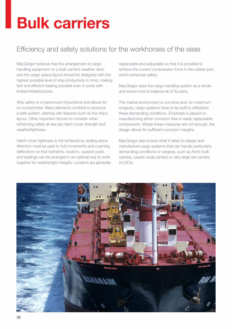
Bulk carriersEfficiency and safety solutions for the workhorses of the seas
MacGregor believes that the arrangement of cargo handling equipment on a bulk carrier’s weather deck and the cargo space layout should be designed with the highest possible level of ship productivity in mind, making fast and efficient loading possible even in ports with limited infrastructures.
Ship safety is of paramount importance and allows for no compromise. Many elements combine to produce a safe system, starting with features such as the ship’s layout. Other important factors to consider when enhancing safety at sea are hatch cover strength and weathertightness.
Hatch cover tightness is not achieved by sealing alone. Attention must be paid to hull movements and coaming deflections so that restraints, locators, support pads and sealings can be arranged in an optimal way to work together for weathertight integrity. Locators are generally
replaceable and adjustable so that it is possible to achieve the correct compression force in the rubber joint, which enhances safety.
MacGregor sees the cargo handling system as a whole and knows how to balance all of its parts.
The marine environment is corrosive and, for maximum longevity, cargo systems have to be built to withstand these demanding conditions. Emphasis is placed on manufacturing either corrosion-free or easily replaceable components. Where these measures are not enough, the design allows for sufficient corrosion margins.
MacGregor also knows what it takes to design and manufacture cargo systems that can handle particularly demanding conditions or cargoes, such as Arctic bulk carriers, caustic soda carriers or very large ore carriers (VLOCs).
39
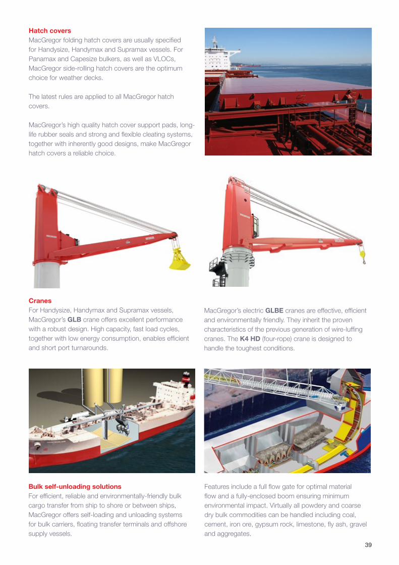
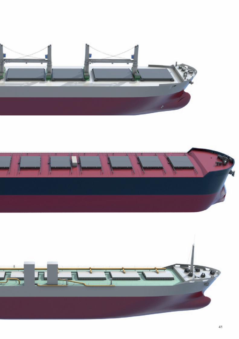
Hatch coversMacGregor folding hatch covers are usually specified for Handysize, Handymax and Supramax vessels. For Panamax and Capesize bulkers, as well as VLOCs, MacGregor side-rolling hatch covers are the optimum choice for weather decks.
The latest rules are applied to all MacGregor hatch covers.
MacGregor’s high quality hatch cover support pads, long-life rubber seals and strong and flexible cleating systems, together with inherently good designs, make MacGregor hatch covers a reliable choice.
Bulk self-unloading solutionsFor efficient, reliable and environmentally-friendly bulk cargo transfer from ship to shore or between ships, MacGregor offers self-loading and unloading systems for bulk carriers, floating transfer terminals and offshore supply vessels.
CranesFor Handysize, Handymax and Supramax vessels, MacGregor’s GLB crane offers excellent performance with a robust design. High capacity, fast load cycles, together with low energy consumption, enables efficient and short port turnarounds.
Features include a full flow gate for optimal material flow and a fully-enclosed boom ensuring minimum environmental impact. Virtually all powdery and coarse dry bulk commodities can be handled including coal, cement, iron ore, gypsum rock, limestone, fly ash, gravel and aggregates.
MacGregor’s electric GLBE cranes are effective, efficient and environmentally friendly. They inherit the proven characteristics of the previous generation of wire-luffing cranes. The K4 HD (four-rope) crane is designed to handle the toughest conditions.
40
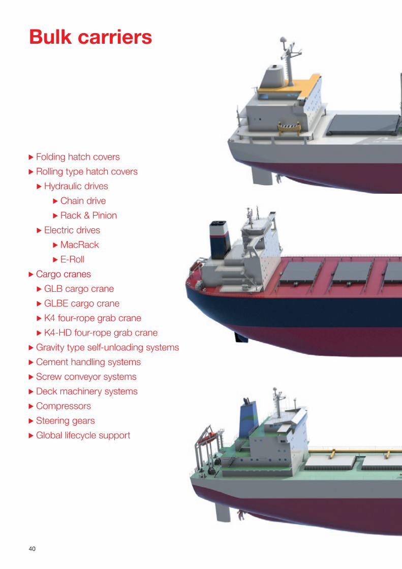
Folding hatch covers
Rolling type hatch covers
Hydraulic drives
Chain drive
Rack & Pinion
Electric drives
MacRack
E-Roll
Cargo cranes
GLB cargo crane
GLBE cargo crane
K4 four-rope grab crane
K4-HD four-rope grab crane
Gravity type self-unloading systems
Cement handling systems
Screw conveyor systems
Deck machinery systems
Compressors
Steering gears
Global lifecycle support
Bulk carriers
41
42
Folding hatch covers
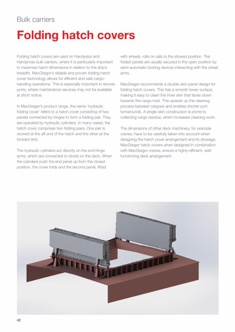
Folding hatch covers are used on Handysize and Handymax bulk carriers, where it is particularly important to maximise hatch dimensions in relation to the ship’s breadth. MacGregor’s reliable and proven folding hatch cover technology allows for efficient and safe cargo-handling operations. This is especially important in remote ports, where maintenance services may not be available at short notice.
In MacGregor’s product range, the name ‘hydraulic folding cover’ refers to a hatch cover consisting of two panels connected by hinges to form a folding pair. They are operated by hydraulic cylinders. In many cases, the hatch cover comprises two folding pairs. One pair is stowed at the aft end of the hatch and the other at the forward end.
The hydraulic cylinders act directly on the end hinge arms, which are connected to stools on the deck. When the cylinders push the end panel up from the closed position, the cover folds and the second panel, fitted
Bulk carriers
with wheels, rolls on rails to the stowed position. The folded panels are usually secured in the open position by semi-automatic locking devices interacting with the wheel arms.
MacGregor recommends a double-skin panel design for folding hatch covers. This has a smooth lower surface, making it easy to clean the inner skin that faces down towards the cargo hold. This speeds up the cleaning process between cargoes and enables shorter port turnarounds. A single-skin construction is prone to collecting cargo residue, which increases cleaning work.
The dimensions of other deck machinery, for example cranes, have to be carefully taken into account when designing the hatch cover arrangement and its stowage. MacGregor hatch covers when designed in combination with MacGregor cranes, ensure a highly-efficient, well-functioning deck arrangement.

43
Rolling hatch covers
Key features• For single and double panel solutions• Hydraulic or electric-drive lifting operations• Rack and pinion or chain drive types • Manual or auto-cleating systems• Bearing pads for ease of installation and to
minimise friction and wear• Reliable sealing solutions to match the hull
deformations• Adjustable fittings (to compensate for wear)• High-quality components for a long service life• Standardised well-proven design and spares
Side-rolling hatch covers are commonly used on the weather decks of larger bulk carriers, such as Panamax and Capesize types. For ore bulk oil carriers (OBOs) and ore oil carriers, hatch covers are designed to withstand internal liquid loads. Side-rolling hatch covers stow in a transverse direction. For open hatch bulk carriers (OHBCs), rolling covers of the piggy-back type (page 30) are preferred if the deck allows little or no free space for stowing the covers when the hatches are open.
A traditional side-rolling cover consists of two panels per hatch, each panel rolling sideways on a pair of transverse ramps. This minimises obstacles to be considered by the shore crane or other loading/unloading device operator when loading and unloading.
When air draft is limited, both panels can in some cases be stowed together on one side. This makes it possible to carry out loading operations from the coaming level. This alternative allows access to one half of the hatch
Bulk carriers
opening, while the other half remains covered by the stowed hatch cover. A single-panel type is mainly used on very large ore carriers (VLOCs) with a sufficiently free deck area. In this hatch cover size range, coordinated design and manufacturing is crucial. MacGregor has a proven record of supplying hatch cover designs and steel structures for VLOCs.
Side-rolling hatch covers can have a variety of different drive systems. The two main options are rack and pinion or chain drive.
Specially developed sealing and securing systems and a superior structural design ensure that the rules and regulations of all classification societies and international authorities are met.
The ship’s hull and hatch coamings will deform in both harbour and sea conditions. These variables must be taken into consideration when selecting the type of hatch cover. Rolling hatch covers with an open web structure and a flat or inclined top plate are superior to a double-skin structure because they allow for torsion of the coaming. Also, their thermal deflections are minimised.
The main variables in side-rolling hatch cover designs are the drive system, the lifting system and the cleating system, which usually depends on the specified lifting system. MacGregor’s early involvement in a project and its extensive knowledge enables it to suggest the best combination of these systems and hatch cover arrangements to match an operator’s requirements.
Single panel system
Two-panel system
44
Drive systems for side-rolling hatch covers
Lifting systems for side-rolling hatch covers
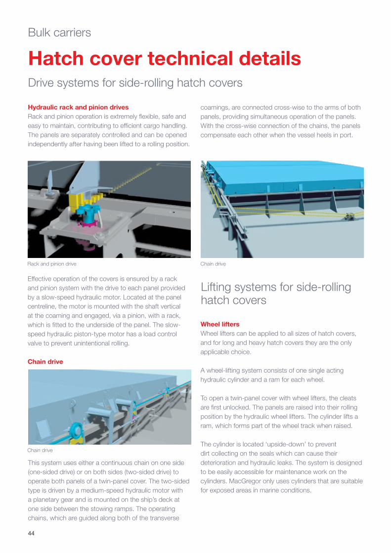
Hydraulic rack and pinion drivesRack and pinion operation is extremely flexible, safe and easy to maintain, contributing to efficient cargo handling. The panels are separately controlled and can be opened independently after having been lifted to a rolling position.
This system uses either a continuous chain on one side (one-sided drive) or on both sides (two-sided drive) to operate both panels of a twin-panel cover. The two-sided type is driven by a medium-speed hydraulic motor with a planetary gear and is mounted on the ship’s deck at one side between the stowing ramps. The operating chains, which are guided along both of the transverse
Effective operation of the covers is ensured by a rack and pinion system with the drive to each panel provided by a slow-speed hydraulic motor. Located at the panel centreline, the motor is mounted with the shaft vertical at the coaming and engaged, via a pinion, with a rack, which is fitted to the underside of the panel. The slow-speed hydraulic piston-type motor has a load control valve to prevent unintentional rolling.
Chain drive
Hatch cover technical detailsBulk carriers
Rack and pinion drive
Chain drive
Chain drive
coamings, are connected cross-wise to the arms of both panels, providing simultaneous operation of the panels. With the cross-wise connection of the chains, the panels compensate each other when the vessel heels in port.
Wheel liftersWheel lifters can be applied to all sizes of hatch covers, and for long and heavy hatch covers they are the only applicable choice.
A wheel-lifting system consists of one single acting hydraulic cylinder and a ram for each wheel.
To open a twin-panel cover with wheel lifters, the cleats are first unlocked. The panels are raised into their rolling position by the hydraulic wheel lifters. The cylinder lifts a ram, which forms part of the wheel track when raised.
The cylinder is located ‘upside-down’ to prevent dirt collecting on the seals which can cause their deterioration and hydraulic leaks. The system is designed to be easily accessible for maintenance work on the cylinders. MacGregor only uses cylinders that are suitable for exposed areas in marine conditions.
45
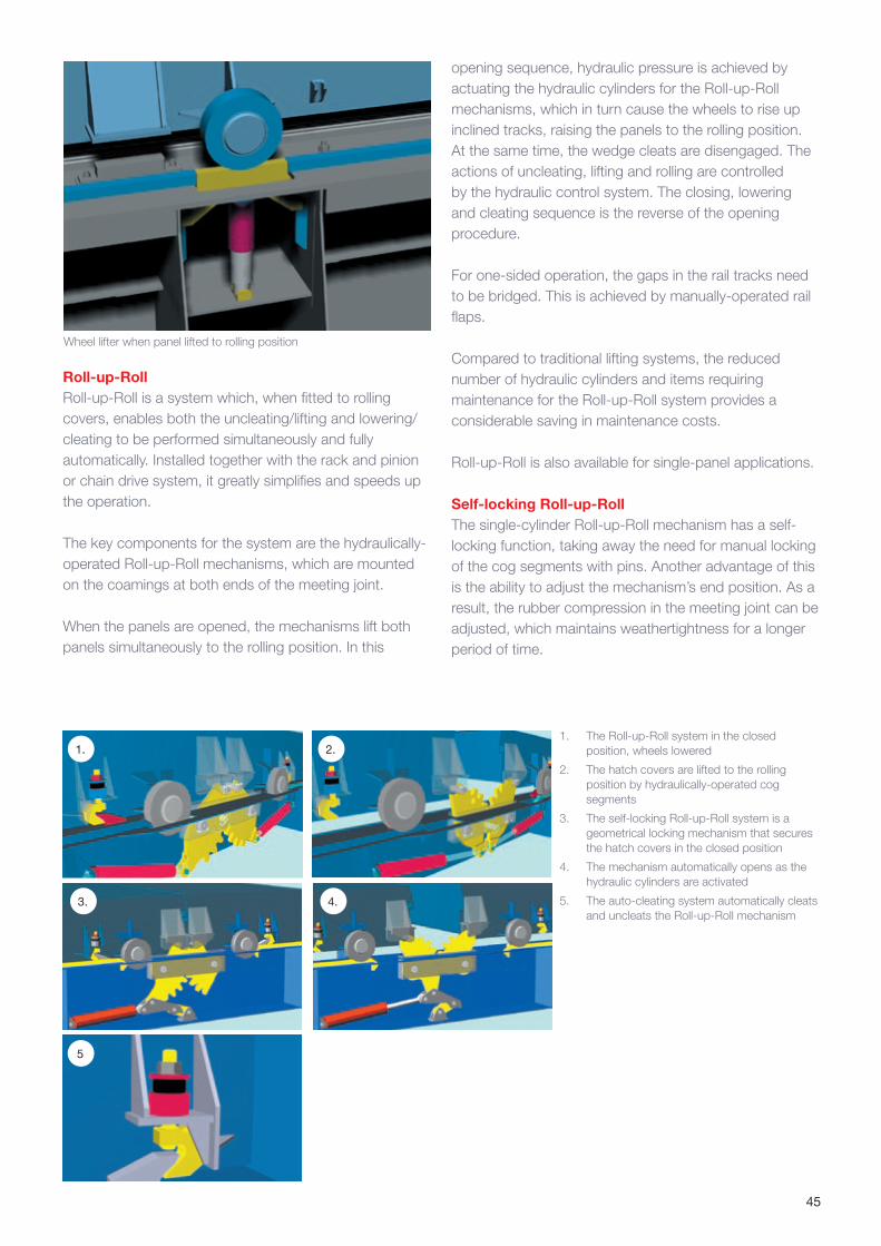
Wheel lifter when panel lifted to rolling position
Roll-up-RollRoll-up-Roll is a system which, when fitted to rolling covers, enables both the uncleating/lifting and lowering/cleating to be performed simultaneously and fully automatically. Installed together with the rack and pinion or chain drive system, it greatly simplifies and speeds up the operation.
The key components for the system are the hydraulically-operated Roll-up-Roll mechanisms, which are mounted on the coamings at both ends of the meeting joint.
When the panels are opened, the mechanisms lift both panels simultaneously to the rolling position. In this
1. The Roll-up-Roll system in the closed position, wheels lowered
2. The hatch covers are lifted to the rolling position by hydraulically-operated cog segments
3. The self-locking Roll-up-Roll system is a geometrical locking mechanism that secures the hatch covers in the closed position
4. The mechanism automatically opens as the hydraulic cylinders are activated
5. The auto-cleating system automatically cleats and uncleats the Roll-up-Roll mechanism
1. 2.
4.
5
3.
opening sequence, hydraulic pressure is achieved by actuating the hydraulic cylinders for the Roll-up-Roll mechanisms, which in turn cause the wheels to rise up inclined tracks, raising the panels to the rolling position. At the same time, the wedge cleats are disengaged. The actions of uncleating, lifting and rolling are controlled by the hydraulic control system. The closing, lowering and cleating sequence is the reverse of the opening procedure.
For one-sided operation, the gaps in the rail tracks need to be bridged. This is achieved by manually-operated rail flaps.
Compared to traditional lifting systems, the reduced number of hydraulic cylinders and items requiring maintenance for the Roll-up-Roll system provides a considerable saving in maintenance costs.
Roll-up-Roll is also available for single-panel applications.
Self-locking Roll-up-RollThe single-cylinder Roll-up-Roll mechanism has a self-locking function, taking away the need for manual locking of the cog segments with pins. Another advantage of this is the ability to adjust the mechanism’s end position. As a result, the rubber compression in the meeting joint can be adjusted, which maintains weathertightness for a longer period of time.

46
Battening, sealing and bearing pad solutions
Cleating systems
Auto-cleating system Auto-cleating systems are used in side-rolling hatch covers together with the roll-up-roll and MacRack mechanisms. When raising the hatch covers, the cleats are simultaneously released. When closing, the covers are cleated at the same time as they are lowered, hence the name ‘auto-cleating’. With an auto-cleat system, cleating is always fully complete and correctly carried out, eliminating the risk of human error.
Quick-acting cleatsManually-operated quick-acting cleats are usually operated from below the coaming. For hatch covers designed for liquid cargo or water ballast loads, special heavy-duty cleats are used.
MacGregor cleating designs always consider the anticipated operating conditions.
Sealing solutionsWeathertightness between the hatch covers and the coaming is generally achieved by rubber seals, allowing for hull and coaming deflections at sea and still maintaining effective sealing. The sealing system is carefully designed to meet the needs of each vessel. Read more about MacGregor sealing solutions on page 61.
Bearing padsBearing pads transmit forces from the hatch cover to the hull at predetermined locations. They are designed to allow for hull deformations and maintain their shape and the position of the hatch cover to ensure weathertightness at sea. A range of bearing pad designs is available to cope with different magnitudes of relative movement.
The highly corrosive environment on bulk carriers, rather than the heavy loads, is the most important consideration when selecting support pads for bulk carrier hatch covers. Using non-corrosive and non-sliding Flexipads ensures that the rubber compression is correctly maintained for a considerably longer time in comparison with steel-to-steel pads. Read more on page 58.
Wheels and bearingsAll wheels are fitted with bearings for reduced friction and easy maintenance. The bearings are fitted with grease nipples that can be easily accessed when the hatch cover panels are in the closed position.
The panels are guided using double-flanged wheels at one end. The wheels at the opposite end are plain.
Control systemsMacGregor’s specially designed and developed control systems ensure optimal control, operation and maintenance of the hatch covers, as well as easy installation.
Bulk carrier folding hatch covers utilise hydraulic control systems. For side-rolling hatch covers, control systems based on hydraulic or fully-electric operation are available.
Electric operation is partly automated, which enhances safety and ease of operation. It also delivers savings in terms of installation time, eliminates the need for hydraulic pipe work and flushing, and frees-up deck space.
Read more about MacGregor’s control systems on page 65.
47
Electric drives offer benefits at every stage. In the building phase, cable wiring is easier than piping and no flushing work is needed. No pump unit is required. There is also no need for high-pressure hydraulics expertise. Together these make the building schedule more flexible.
In operation, there is no risk of hydraulic oil leaks and the system is maintenance-friendly. The operation position is not limited and energy is saved because there is no continuous running of the system. Electric solutions are reliable in all weathers, easy to operate and monitor and safe for the cargo.
E-RollWork on the electric side-rolling hatch cover started in 2001 in response to the Japanese car industry’s ambition to make its supply chain as ‘green’ as possible. MacGregor’s answer was the E-Roll side-rolling hatch cover control system. E-roll has single-button control. Hatch covers are controlled by a portable control box connected to outlets provided for each hatch. The electric motors are controlled by an inverter and PLC. Automatic cleating is available using auto-cleats.
Electric drives for side-rolling hatch covers
Each E-Roll side-rolling hatch cover comprises two panels, one on each side, which are opened by a geared electric motor connected to a chain drive after being raised (‘Roll-up-Roll’) by electrically-powered cylinders. One complete roll up/down and open/close operation is carried out automatically when the operator pushes a single button. Smooth operation is ensured by an inverter and PLC control.
The concept can use both a rack and pinion drive as well as a chain drive. To minimise the number of electrically-powered cylinders (or so called ‘electric screws’) the Roll-up-Roll system is preferred. This system not only lifts the panels into the rolling position, but can also automatically cleat them.
E-Roll paved the way for new product generations such as MacRack.
Electric Roll-up-Roll lifter and auto-cleats
MacGregor has pioneered the replacement of hydraulic cylinders with electric solutions. The company’s lengthy experience and commitment to the development of electric drive technology, makes original MacGregor electric drives a reliable choice.
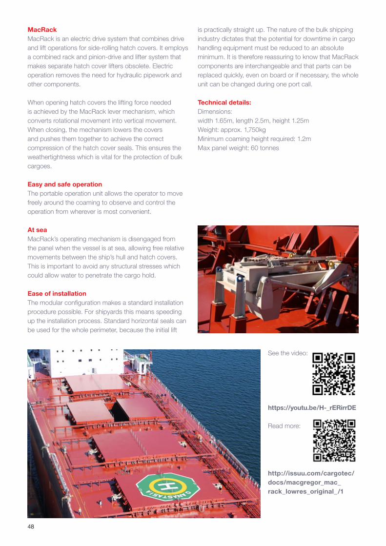
48
MacRackMacRack is an electric drive system that combines drive and lift operations for side-rolling hatch covers. It employs a combined rack and pinion-drive and lifter system that makes separate hatch cover lifters obsolete. Electric operation removes the need for hydraulic pipework and other components.
When opening hatch covers the lifting force needed is achieved by the MacRack lever mechanism, which converts rotational movement into vertical movement. When closing, the mechanism lowers the covers and pushes them together to achieve the correct compression of the hatch cover seals. This ensures the weathertightness which is vital for the protection of bulk cargoes.
Easy and safe operationThe portable operation unit allows the operator to move freely around the coaming to observe and control the operation from wherever is most convenient.
At seaMacRack’s operating mechanism is disengaged from the panel when the vessel is at sea, allowing free relative movements between the ship’s hull and hatch covers. This is important to avoid any structural stresses which could allow water to penetrate the cargo hold.
Ease of installation The modular configuration makes a standard installation procedure possible. For shipyards this means speeding up the installation process. Standard horizontal seals can be used for the whole perimeter, because the initial lift
See the video:
https://youtu.be/H-_rERirrDE
Read more:
http://issuu.com/cargotec/docs/macgregor_mac_rack_lowres_original_/1
is practically straight up. The nature of the bulk shipping industry dictates that the potential for downtime in cargo handling equipment must be reduced to an absolute minimum. It is therefore reassuring to know that MacRack components are interchangeable and that parts can be replaced quickly, even on board or if necessary, the whole unit can be changed during one port call.
Technical details:Dimensions: width 1.65m, length 2.5m, height 1.25mWeight: approx. 1,750kgMinimum coaming height required: 1.2mMax panel weight: 60 tonnes
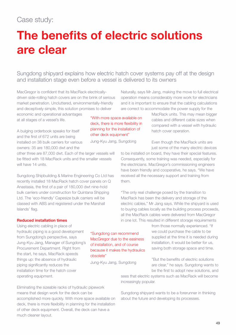
49
The benefits of electric solutions are clear
Sungdong shipyard explains how electric hatch cover systems pay off at the design and installation stage even before a vessel is delivered to its owners
MacGregor is confident that its MacRack electrically-driven side-rolling hatch covers are on the brink of serious market penetration. Uncluttered, environmentally-friendly and deceptively simple, this solution promises to deliver economic and operational advantages at all stages of a vessel’s life.
A bulging orderbook speaks for itself and the first of 672 units are being installed on 38 bulk carriers for various owners: 35 are 180,000 dwt and the other three are 87,000 dwt. Each of the larger vessels will be fitted with 18 MacRack units and the smaller vessels will have 14 units.
Sungdong Shipbuilding & Marine Engineering Co Ltd has recently installed 18 MacRack hatch cover panels on Q Anastasia, the first of a pair of 180,000 dwt nine-hold bulk carriers under construction for Quintana Shipping Ltd. The ‘eco-friendly’ Capesize bulk carriers will be classed with ABS and registered under the Marshall Islands’ flag.
Reduced installation times Using electric cabling in place of hydraulic piping is a good development from Sungdong’s perspective, says Jung-Kyu Jang, Manager of Sungdong’s Procurement Department. Right from the start, he says, MacRack speeds things up: the absence of hydraulic piping significantly reduces the installation time for the hatch cover operating equipment.
Eliminating the sizeable racks of hydraulic pipework means that design work for the deck can be accomplished more quickly. With more space available on deck, there is more flexibility in planning for the installation of other deck equipment. Overall, the deck can have a much cleaner layout.
Naturally, says Mr Jang, making the move to full electrical operation means considerably more work for electricians and it is important to ensure that the cabling calculations are correct to accommodate the power supply for the
MacRack units. This may mean bigger cables and different cable sizes when compared with a vessel with hydraulic hatch cover operation.
Even though the MacRack units are just some of the many electric devices
to be installed on board, they have their special features. Consequently, some training was needed, especially for the electricians. MacGregor’s commissioning engineers have been friendly and cooperative, he says. “We have received all the necessary support and training from them.
“The only real challenge posed by the transition to MacRack has been the delivery and storage of the electric cables,” Mr Jang says. While the shipyard is used to buying cables locally as the building process proceeds, all the MacRack cables were delivered from MacGregor in one lot. This resulted in different storage requirements
from those normally experienced. “If we could purchase the cable to be supplied at the time it is needed during installation, it would be better for us, saving both storage space and time.
”But the benefits of electric solutions are clear,” he says. Sungdong wants to be the first to adopt new solutions, and
sees that electric systems such as MacRack will become increasingly popular.
Sungdong shipyard wants to be a forerunner in thinking about the future and developing its processes.
“With more space available on deck, there is more flexibility in planning for the installation of other deck equipment”
Jung-Kyu Jang, Sungdong
“Sungdong can recommend MacGregor due to the easiness of installation, and of course because it makes the hydraulics obsolete”
Jung-Kyu Jang, Sungdong
Case study:
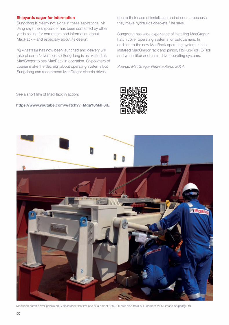
50
MacRack hatch cover panels on Q Anastasia; the first of a of a pair of 180,000 dwt nine-hold bulk carriers for Quintana Shipping Ltd
Shipyards eager for information Sungdong is clearly not alone in these aspirations. Mr Jang says the shipbuilder has been contacted by other yards asking for comments and information about MacRack – and especially about its design.
“Q Anastasia has now been launched and delivery will take place in November, so Sungdong is as excited as MacGregor to see MacRack in operation. Shipowners of course make the decision about operating systems but Sungdong can recommend MacGregor electric drives
due to their ease of installation and of course because they make hydraulics obsolete,” he says.
Sungdong has wide experience of installing MacGregor hatch cover operating systems for bulk carriers. In addition to the new MacRack operating system, it has installed MacGregor rack and pinion, Roll-up-Roll, E-Roll and wheel lifter and chain drive operating systems.
Source: MacGregor News autumn 2014.
See a short film of MacRack in action:
https://www.youtube.com/watch?v=MgaY8MJF8rE
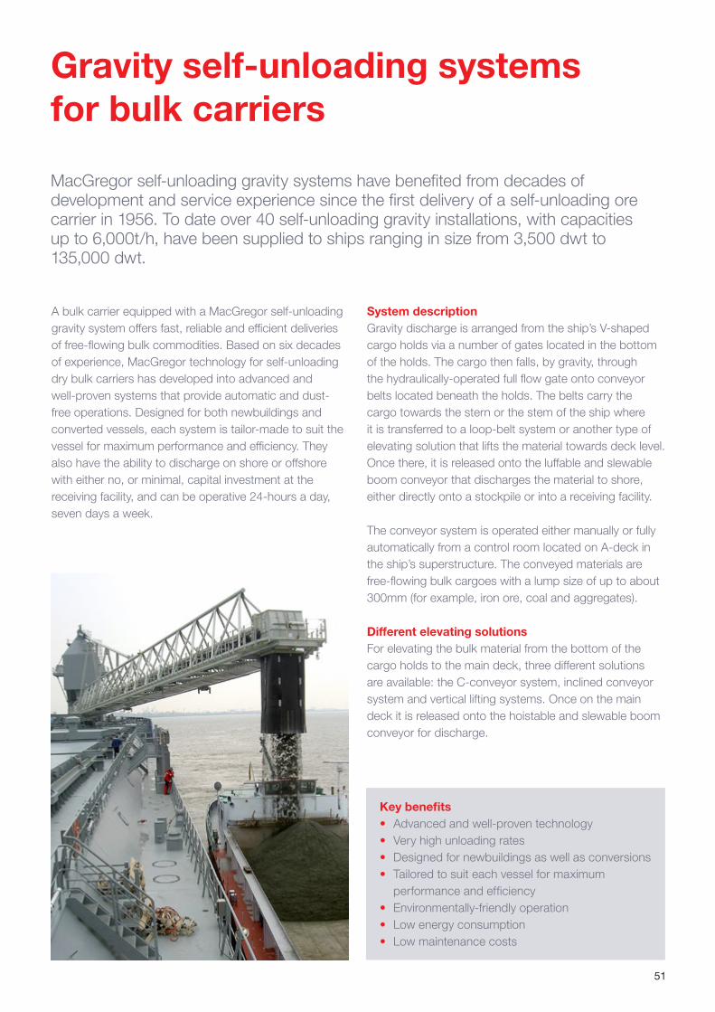
51
MacGregor self-unloading gravity systems have benefited from decades of development and service experience since the first delivery of a self-unloading ore carrier in 1956. To date over 40 self-unloading gravity installations, with capacities up to 6,000t/h, have been supplied to ships ranging in size from 3,500 dwt to 135,000 dwt.
A bulk carrier equipped with a MacGregor self-unloading gravity system offers fast, reliable and efficient deliveries of free-flowing bulk commodities. Based on six decades of experience, MacGregor technology for self-unloading dry bulk carriers has developed into advanced and well-proven systems that provide automatic and dust-free operations. Designed for both newbuildings and converted vessels, each system is tailor-made to suit the vessel for maximum performance and efficiency. They also have the ability to discharge on shore or offshore with either no, or minimal, capital investment at the receiving facility, and can be operative 24-hours a day, seven days a week.
Key benefits• Advanced and well-proven technology • Very high unloading rates• Designed for newbuildings as well as conversions • Tailored to suit each vessel for maximum
performance and efficiency• Environmentally-friendly operation• Low energy consumption• Low maintenance costs
System descriptionGravity discharge is arranged from the ship’s V-shaped cargo holds via a number of gates located in the bottom of the holds. The cargo then falls, by gravity, through the hydraulically-operated full flow gate onto conveyor belts located beneath the holds. The belts carry the cargo towards the stern or the stem of the ship where it is transferred to a loop-belt system or another type of elevating solution that lifts the material towards deck level. Once there, it is released onto the luffable and slewable boom conveyor that discharges the material to shore, either directly onto a stockpile or into a receiving facility.
The conveyor system is operated either manually or fully automatically from a control room located on A-deck in the ship’s superstructure. The conveyed materials are free-flowing bulk cargoes with a lump size of up to about 300mm (for example, iron ore, coal and aggregates).
Different elevating solutionsFor elevating the bulk material from the bottom of the cargo holds to the main deck, three different solutions are available: the C-conveyor system, inclined conveyor system and vertical lifting systems. Once on the main deck it is released onto the hoistable and slewable boom conveyor for discharge.
Gravity self-unloading systems for bulk carriers
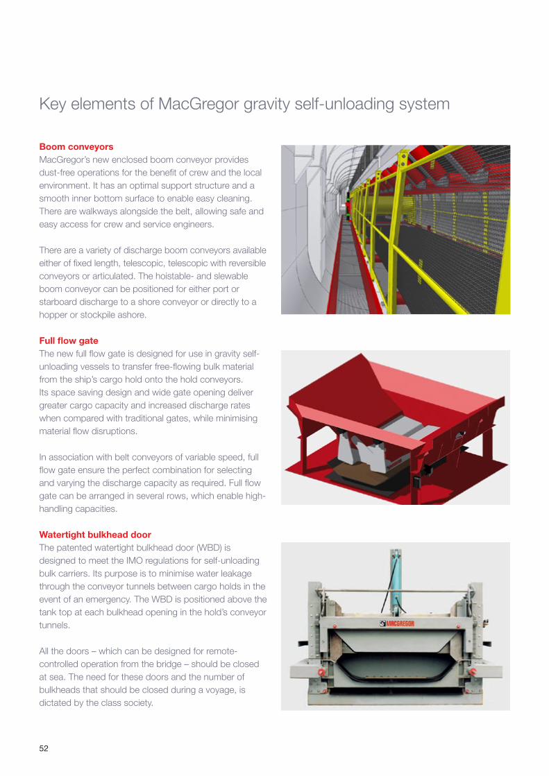
52
Boom conveyorsMacGregor’s new enclosed boom conveyor provides dust-free operations for the benefit of crew and the local environment. It has an optimal support structure and a smooth inner bottom surface to enable easy cleaning. There are walkways alongside the belt, allowing safe and easy access for crew and service engineers.
There are a variety of discharge boom conveyors available either of fixed length, telescopic, telescopic with reversible conveyors or articulated. The hoistable- and slewable boom conveyor can be positioned for either port or starboard discharge to a shore conveyor or directly to a hopper or stockpile ashore.
Full flow gateThe new full flow gate is designed for use in gravity self-unloading vessels to transfer free-flowing bulk material from the ship’s cargo hold onto the hold conveyors. Its space saving design and wide gate opening deliver greater cargo capacity and increased discharge rates when compared with traditional gates, while minimising material flow disruptions.
In association with belt conveyors of variable speed, full flow gate ensure the perfect combination for selecting and varying the discharge capacity as required. Full flow gate can be arranged in several rows, which enable high-handling capacities.
Watertight bulkhead doorThe patented watertight bulkhead door (WBD) is designed to meet the IMO regulations for self-unloading bulk carriers. Its purpose is to minimise water leakage through the conveyor tunnels between cargo holds in the event of an emergency. The WBD is positioned above the tank top at each bulkhead opening in the hold’s conveyor tunnels.
All the doors – which can be designed for remote-controlled operation from the bridge – should be closed at sea. The need for these doors and the number of bulkheads that should be closed during a voyage, is dictated by the class society.
Key elements of MacGregor gravity self-unloading system
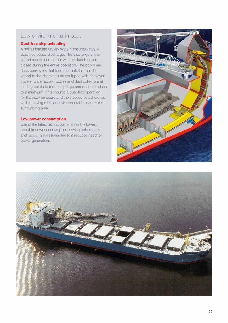
53
Low environmental impactDust-free ship unloadingA self-unloading gravity system ensures virtually dust-free vessel discharge. The discharge of the vessel can be carried out with the hatch covers closed during the entire operation. The boom and deck conveyors that feed the material from the vessel to the shore can be equipped with conveyor covers, water spray nozzles and dust collectors at loading points to reduce spillage and dust emissions to a minimum. This ensures a dust-free operation for the crew on board and the stevedores ashore, as well as having minimal environmental impact on the surrounding area.
Low power consumption Use of the latest technology ensures the lowest possible power consumption, saving both money and reducing emissions due to a reduced need for power generation.
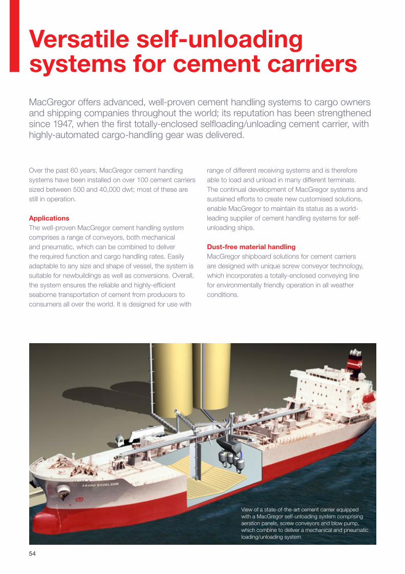
54
MacGregor offers advanced, well-proven cement handling systems to cargo owners and shipping companies throughout the world; its reputation has been strengthened since 1947, when the first totally-enclosed selfloading/unloading cement carrier, with highly-automated cargo-handling gear was delivered.
Over the past 60 years, MacGregor cement handling systems have been installed on over 100 cement carriers sized between 500 and 40,000 dwt; most of these are still in operation.
Applications The well-proven MacGregor cement handling system comprises a range of conveyors, both mechanical and pneumatic, which can be combined to deliver the required function and cargo handling rates. Easily adaptable to any size and shape of vessel, the system is suitable for newbuildings as well as conversions. Overall, the system ensures the reliable and highly-efficient seaborne transportation of cement from producers to consumers all over the world. It is designed for use with
range of different receiving systems and is therefore able to load and unload in many different terminals. The continual development of MacGregor systems and sustained efforts to create new customised solutions, enable MacGregor to maintain its status as a world-leading supplier of cement handling systems for self-unloading ships.
Dust-free material handling MacGregor shipboard solutions for cement carriers are designed with unique screw conveyor technology, which incorporates a totally-enclosed conveying line for environmentally friendly operation in all weather conditions.
View of a state-of-the-art cement carrier equipped with a MacGregor self-unloading system comprising aeration panels, screw conveyors and blow pump, which combine to deliver a mechanical and pneumatic loading/unloading system
Versatile self-unloading systems for cement carriers
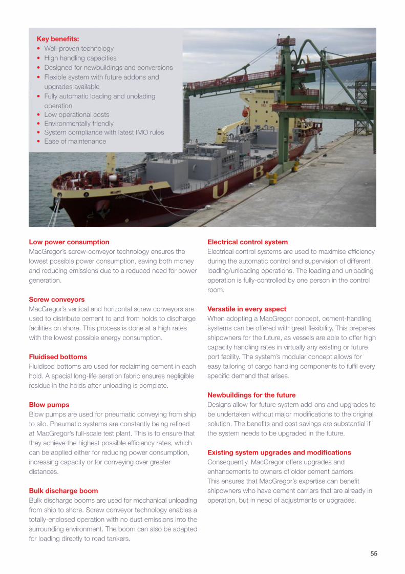
55
Key benefits:• Well-proven technology• High handling capacities• Designed for newbuildings and conversions• Flexible system with future addons and
upgrades available• Fully automatic loading and unolading
operation• Low operational costs• Environmentally friendly• System compliance with latest IMO rules• Ease of maintenance
Low power consumption MacGregor’s screw-conveyor technology ensures the lowest possible power consumption, saving both money and reducing emissions due to a reduced need for power generation.
Screw conveyors MacGregor’s vertical and horizontal screw conveyors are used to distribute cement to and from holds to discharge facilities on shore. This process is done at a high rates with the lowest possible energy consumption.
Fluidised bottoms Fluidised bottoms are used for reclaiming cement in each hold. A special long-life aeration fabric ensures negligible residue in the holds after unloading is complete.
Blow pumps Blow pumps are used for pneumatic conveying from ship to silo. Pneumatic systems are constantly being refined at MacGregor’s full-scale test plant. This is to ensure that they achieve the highest possible efficiency rates, which can be applied either for reducing power consumption, increasing capacity or for conveying over greater distances.
Bulk discharge boom Bulk discharge booms are used for mechanical unloading from ship to shore. Screw conveyor technology enables a totally-enclosed operation with no dust emissions into the surrounding environment. The boom can also be adapted for loading directly to road tankers.
Electrical control system Electrical control systems are used to maximise efficiency during the automatic control and supervision of different loading/unloading operations. The loading and unloading operation is fully-controlled by one person in the control room.
Versatile in every aspect When adopting a MacGregor concept, cement-handling systems can be offered with great flexibility. This prepares shipowners for the future, as vessels are able to offer high capacity handling rates in virtually any existing or future port facility. The system’s modular concept allows for easy tailoring of cargo handling components to fulfil every specific demand that arises.
Newbuildings for the future Designs allow for future system add-ons and upgrades to be undertaken without major modifications to the original solution. The benefits and cost savings are substantial if the system needs to be upgraded in the future.
Existing system upgrades and modifications Consequently, MacGregor offers upgrades and enhancements to owners of older cement carriers. This ensures that MacGregor’s expertise can benefit shipowners who have cement carriers that are already in operation, but in need of adjustments or upgrades.
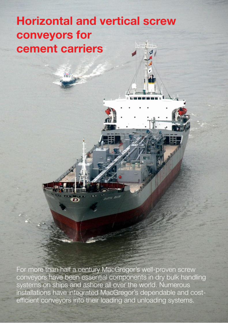
56
For more than half a century MacGregor’s well-proven screw conveyors have been essential components in dry bulk handling systems on ships and ashore all over the world. Numerous installations have integrated MacGregor’s dependable and cost-efficient conveyors into their loading and unloading systems.
Horizontal and vertical screw conveyors for cement carriers
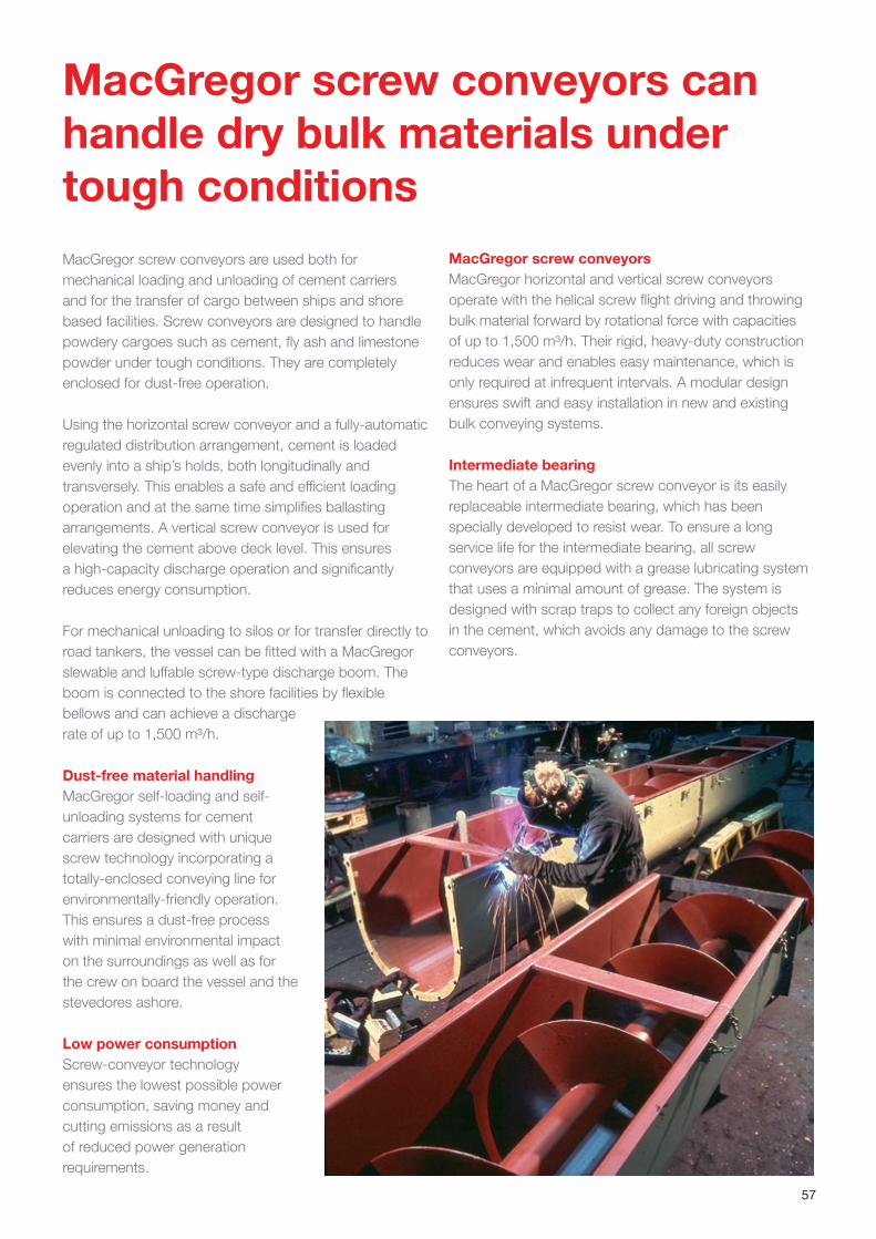
57
MacGregor screw conveyors are used both for mechanical loading and unloading of cement carriers and for the transfer of cargo between ships and shore based facilities. Screw conveyors are designed to handle powdery cargoes such as cement, fly ash and limestone powder under tough conditions. They are completely enclosed for dust-free operation.
Using the horizontal screw conveyor and a fully-automatic regulated distribution arrangement, cement is loaded evenly into a ship’s holds, both longitudinally and transversely. This enables a safe and efficient loading operation and at the same time simplifies ballasting arrangements. A vertical screw conveyor is used for elevating the cement above deck level. This ensures a high-capacity discharge operation and significantly reduces energy consumption.
For mechanical unloading to silos or for transfer directly to road tankers, the vessel can be fitted with a MacGregor slewable and luffable screw-type discharge boom. The boom is connected to the shore facilities by flexible bellows and can achieve a discharge rate of up to 1,500 m³/h.
Dust-free material handling MacGregor self-loading and self-unloading systems for cement carriers are designed with unique screw technology incorporating a totally-enclosed conveying line for environmentally-friendly operation. This ensures a dust-free process with minimal environmental impact on the surroundings as well as for the crew on board the vessel and the stevedores ashore.
Low power consumption Screw-conveyor technology ensures the lowest possible power consumption, saving money and cutting emissions as a result of reduced power generation requirements.
MacGregor screw conveyors MacGregor horizontal and vertical screw conveyors operate with the helical screw flight driving and throwing bulk material forward by rotational force with capacities of up to 1,500 m³/h. Their rigid, heavy-duty construction reduces wear and enables easy maintenance, which is only required at infrequent intervals. A modular design ensures swift and easy installation in new and existing bulk conveying systems.
Intermediate bearing The heart of a MacGregor screw conveyor is its easily replaceable intermediate bearing, which has been specially developed to resist wear. To ensure a long service life for the intermediate bearing, all screw conveyors are equipped with a grease lubricating system that uses a minimal amount of grease. The system is designed with scrap traps to collect any foreign objects in the cement, which avoids any damage to the screw conveyors.
MacGregor screw conveyors can handle dry bulk materials under tough conditions
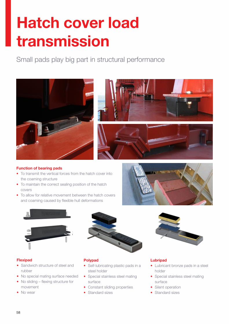
58
Hatch cover load transmissionSmall pads play big part in structural performance
Function of bearing pads• To transmit the vertical forces from the hatch cover into
the coaming structure• To maintain the correct sealing position of the hatch
covers • To allow for relative movement between the hatch covers
and coaming caused by flexible hull deformations
Lubripad• Lubricant bronze pads in a steel
holder• Special stainless steel mating
surface• Silent operation• Standard sizes
Polypad• Self-lubricating plastic pads in a
steel holder• Special stainless steel mating
surface• Constant sliding properties• Standard sizes
Flexipad• Sandwich structure of steel and
rubber• No special mating surface needed• No sliding – flexing structure for
movement• No wear
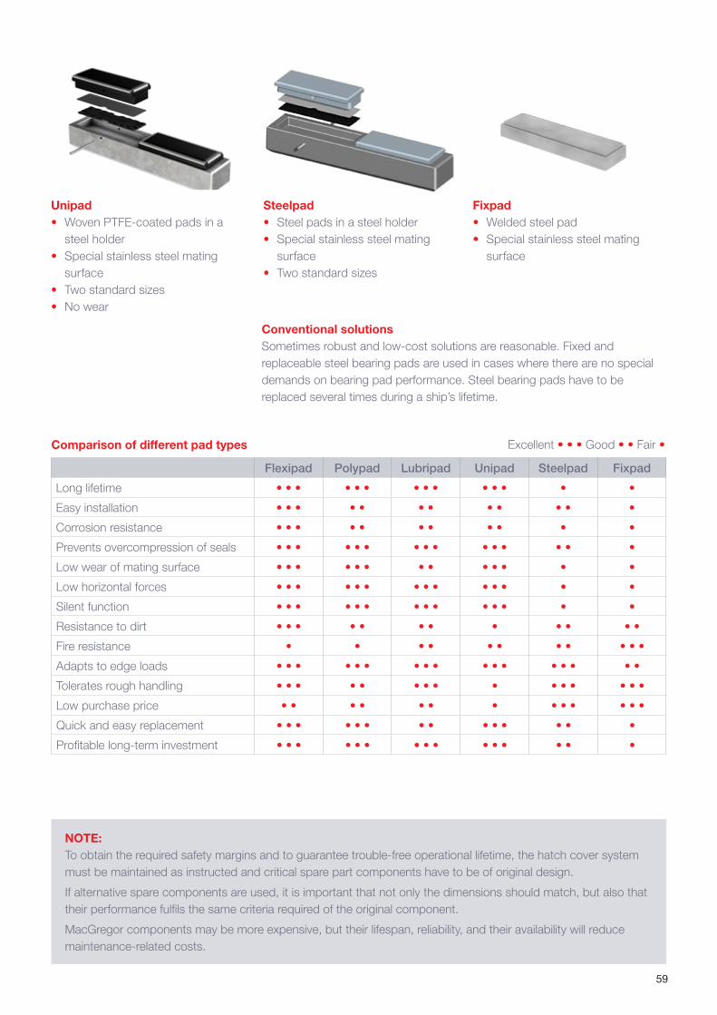
59
Fixpad• Welded steel pad• Special stainless steel mating
surface
Steelpad• Steel pads in a steel holder• Special stainless steel mating
surface• Two standard sizes
Conventional solutionsSometimes robust and low-cost solutions are reasonable. Fixed and replaceable steel bearing pads are used in cases where there are no special demands on bearing pad performance. Steel bearing pads have to be replaced several times during a ship’s lifetime.
NOTE:To obtain the required safety margins and to guarantee trouble-free operational lifetime, the hatch cover system must be maintained as instructed and critical spare part components have to be of original design.
If alternative spare components are used, it is important that not only the dimensions should match, but also that their performance fulfils the same criteria required of the original component.
MacGregor components may be more expensive, but their lifespan, reliability, and their availability will reduce maintenance-related costs.
Flexipad Polypad Lubripad Unipad Steelpad Fixpad
Long lifetime • • • • • • • • • • • • • •
Easy installation • • • • • • • • • • • •
Corrosion resistance • • • • • • • • • • •
Prevents overcompression of seals • • • • • • • • • • • • • • •
Low wear of mating surface • • • • • • • • • • • • •
Low horizontal forces • • • • • • • • • • • • • •
Silent function • • • • • • • • • • • • • •
Resistance to dirt • • • • • • • • • • • •
Fire resistance • • • • • • • • • • •
Adapts to edge loads • • • • • • • • • • • • • • • • •
Tolerates rough handling • • • • • • • • • • • • • • •
Low purchase price • • • • • • • • • • • • •
Quick and easy replacement • • • • • • • • • • • • • •
Profitable long-term investment • • • • • • • • • • • • • • •
Comparison of different pad types Excellent • • • Good • • Fair •
Unipad• Woven PTFE-coated pads in a
steel holder• Special stainless steel mating
surface• Two standard sizes• No wear

60
Small pads play big partin structural performanceUsing the wrong material or ignoring the need to replace worn pads, can lead to cracks in hatch covers and coamings after two years of operation
Hatch cover bearing pads transfer the weight of the cover, and any cargo it may be carrying, to the ship’s hull while allowing for relative movement between the cover and the hatch coaming caused by hull flexing in a seaway. They must also maintain the correct compression on the hatch cover seal and avoid wearing damage to the coaming/hatch cover interface.
“Bearing pads may be relatively small, but the part they play is big,” says Jyrki Mäenpää, Technical Manager, Dry Cargo. “As bearing pads transfer weight, lateral forces are generated that are then transmitted to the ship’s coaming and hatch cover structures. These forces are used in fatigue strength analysis at the newbuilding stage, and subsequently, the structures are designed around these calculations.
“Over time low-friction bearing pads do get worn, and the amount of wear for an individual pad depends on its location and actual loading – therefore they should be replaced on a progressive basis.
“If alternative spare components are used, it is extremely important not only that the dimensions are compatible, but also that their performance fulfils the same criteria required of the original component.
“To obtain the required safety margins and to guarantee a trouble-free operational lifetime, the hatch cover system has to be maintained as instructed, and critical spare part components, such as the hatch cover bearing pads, have to be of original design.
“Friction and wear behaviour are the most critical factors, and it is impossible to judge these without testing them
in a real environment. If the friction coefficient of a bearing pad is doubled, for example raised from 0.2 to 0.4 – which can easily happen when a low-quality spare component is used – the calculated life-span of a steel structure is diminishing by a factor of ten. In other
words, the safe operational period of coaming and hatch cover structures drops from 20 to two years!
“Also, if low-friction bearing pads are replaced with high-friction spare components, cracks are likely to be generated in the steel structures.
“Although there are numerous sliding bearing materials available, only a few are suitable for hatch cover bearing pad use, as most do not meet the criteria defined in the original specification. This is because there can be great variations in sliding and wear properties of different bearing materials and this is applicable to both bronze and plastic composites.”
Source: MacGregor News autumn 2011.A range of reliable optionsMacGregor’s portfolio of bearing pads is comprehensive, ranging from a traditional steel-to-steel type to the most advanced solutions using the latest materials and technology.
MacGregor offers tested and proven bearing pad solutions that mean trouble-free operations and safe cargo handling for all types of vessels. Continual investigation over many years has resulted in a range of options, including the Lubripad (bronze/PTFE), the Flexipad (steel/rubber), the Unipad (woven PTFE) and the Polypad (self-lubricating polymer-based).
When replacing the pads, serious consequences can result if changes are made to the features originally specified for the system
A low-quality spare can reduce the steel structure’s life-span by a factor of ten
Case study:
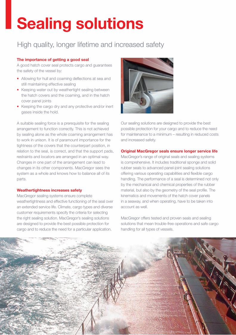
61
Sealing solutionsHigh quality, longer lifetime and increased safety
The importance of getting a good sealA good hatch cover seal protects cargo and guarantees the safety of the vessel by:
• Allowing for hull and coaming deflections at sea and still maintaining effective sealing
• Keeping water out by weathertight sealing between the hatch covers and the coaming, and in the hatch cover panel joints
• Keeping the cargo dry and any protective and/or inert gases inside the hold.
A suitable sealing force is a prerequisite for the sealing arrangement to function correctly. This is not achieved by sealing alone as the whole coaming arrangement has to work in unison. It is of paramount importance for the tightness of the covers that the counterpart position, in relation to the seal, is correct, and that the support pads, restraints and locators are arranged in an optimal way. Changes in one part of the arrangement can lead to changes in its other components. MacGregor sees the system as a whole and knows how to balance all of its parts.
Weathertightness increases safetyMacGregor sealing systems ensure complete weathertightness and effective functioning of the seal over an extended service life. Climate, cargo types and diverse customer requirements specify the criteria for selecting the right sealing solution. MacGregor’s sealing solutions are designed to provide the best possible protection for cargo and to reduce the need for a particular application.
Our sealing solutions are designed to provide the best possible protection for your cargo and to reduce the need for maintenance to a minimum – resulting in reduced costs and increased safety.
Original MacGregor seals ensure longer service life MacGregor’s range of original seals and sealing systems is comprehensive. It includes traditional sponge and solid rubber seals to advanced panel-joint sealing solutions offering various operating capabilities and flexible cargo handling. The performance of a seal is determined not only by the mechanical and chemical properties of the rubber material, but also by the geometry of the seal profile. The kinematics and movements of the hatch cover panels in a seaway, and when operating, have to be taken into account as well.
MacGregor offers tested and proven seals and sealing solutions that mean trouble-free operations and safe cargo handling for all types of vessels.

62
Selection and operation of our seals
C Gasket• Sliding C-profile• Non-sequential sealing for joints
between lift-away pontoon hatches
• Robust profile, bolted to rubber channel
• Easy and reliable operation• Recommended for two-panel
hatches
Sponge• Traditional hatch cover seal• Minimal permanent set• High ozone resistance and tensile
strength• Mainly for older ships where
investments in maintenance and/or repair are not economical
FlexSeal• Minimal permanent set• Improved solution to replace
sponge seals• Excellent service life expectancy• Solid rubber does not absorb
water, maintains its original shape and prevents corrosion
• Shape of ‘wings’ and ‘jags’ gives it an optimum weathertight fit
• Oil-resistant and arctic types available
Omega• Non-sequential operation• Function is based on pressurised
air. Unpressurised, a weathertight seal is formed against its rubber counterpart in the joint. For lifting, the two air hoses inside the seal are pressurised and the seal’s profile retracts from its counterpart. In emergencies, Omega panels can also be operated without air pressure.
• Uses the ship’s standard compressed air system => no special vacuum pumps needed
Omega Lite• ‘Simplified’ Omega – without
retractable features• Non-sequential passive sealing for
joints between lift-away pontoon hatches
• Replaces active Omega with minimum steel work
• Cost-effective
Cat Profile• No compression bar required• Reduced installation/maintenance
costs• Works against any surface• No restriction of lateral movement• Minimal permanent rubber set• Abrasion resistant• Optimised rubber material for
minimal wear• Fire-retardant and Arctic types
available
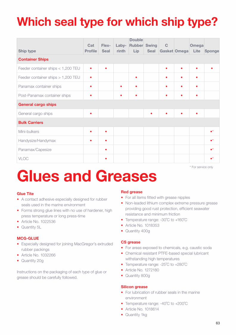
63
Which seal type for which ship type?
Ship typeCat
ProfileFlex- Seal
Laby-rinth
Double Rubber
LipSwing Seal
C Gasket Omega
Omega Lite Sponge
Container Ships
Feeder container ships < 1,200 TEU • • • • • •
Feeder container ships > 1,200 TEU • • • • •
Panamax container ships • • • • • •
Post-Panamax container ships • • • • • •
General cargo ships
General cargo ships • • • • •
Bulk Carriers
Mini-bulkers • • •*
Handysize/Handymax • • •*
Panamax/Capesize • •*
VLOC • •*
Red grease• For all items fitted with grease nipples• Non-leaded lithium complex extreme pressure grease
providing good rust protection, efficient seawater resistance and minimum friction
• Temperature range: -30˚C to +160˚C• Article No. 1018353• Quantity 400g
CS grease• For areas exposed to chemicals, e.g. caustic soda • Chemical resistant PTFE-based special lubricant
withstanding high temperatures• Temperature range: -25˚C to +280˚C• Article No. 1272180• Quantity 800g
Silicon grease• For lubrication of rubber seals in the marine
environment• Temperature range: -40˚C to +200˚C• Article No. 1018614• Quantity 1kg
Glues and GreasesGlue Tite• A contact adhesive especially designed for rubber
seals used in the marine environment• Forms strong glue lines with no use of hardener, high
press temperature or long press-time• Article No. 1022536• Quantity 5L
MCG-GLUE• Especially designed for joining MacGregor’s extruded
rubber packings• Article No. 1032266• Quantity 20g
Instructions on the packaging of each type of glue or grease should be carefully followed.
* For service only

64
Relative movements between the hull and the hatch cover
The hull of a vessel always experiences flexible deformations, especially in rough seas. The greater the size of the hatches in relation to the deck area, the more significant the deformations, as well as their implications on the hatch cover design.
Hull deformations at sea and in portThe large size of the hatches reduces the torsional stiffness of the hull. In rough seas this causes twisting and diagonal changes in the hatchway, as well as warping of the deck plane. The longitudinal bending of the hull, known as hogging and sagging, causes considerable changes in hatch cover length. A third major type of flexible deformation is bending of the sides inwards and outwards. This not only occurs at sea but also in port when the vessel’s draught changes due to variations in the load condition. In winter conditions the pressure of ice contributes to the flexible deformations of the hull.
Flexible deformations of the hull result in relative movements between the hatch cover and the coaming. This calls for special design solutions for maintaining the weathertight integrity of the vessel to protect the cargo in all conditions, and for keeping maintenance costs under control. The impact of these relative movements can be minimised by the design of sealing arrangements, steel structures, and bearing pads/stoppers. Operating components such as cleats, wheels, intermediate hinges and end hinges are also important factors in maintaining weathertightness. With a suitable stopper arrangement, the longitudinal and athwartships relative movements can be controlled and divided so that weathertightness
can be maintained in all circumstances. This implies that the magnitude of the displacement does not exceed the allowed variation of seal compression at any location.
Coaming arrangement designed to withstand deformation forces To ensure the best match of hatch covers for a planned vessel and for MacGregor to undertake basic design work, the shipyard must be able to provide information relating to flexible hull deformation calculations under different conditions.
To maintain hatch cover tightness, it is essential that sealing systems, bearing pads, restraints and locators are arranged in an optimal way and work together. On bulk carriers, for example, all components are located outside the sealing area to avoid possibly damaging contact with the cargo. The transverse locators are easy to install. They are adjustable to achieve the correct compression force in the rubber joint.
To ensure that the panels can be secured to withstand huge lateral loads in rough seas, the strength of the hatch cover components is just as important as the strength of the steel structure.
Hull deformation – exaggerated illustration
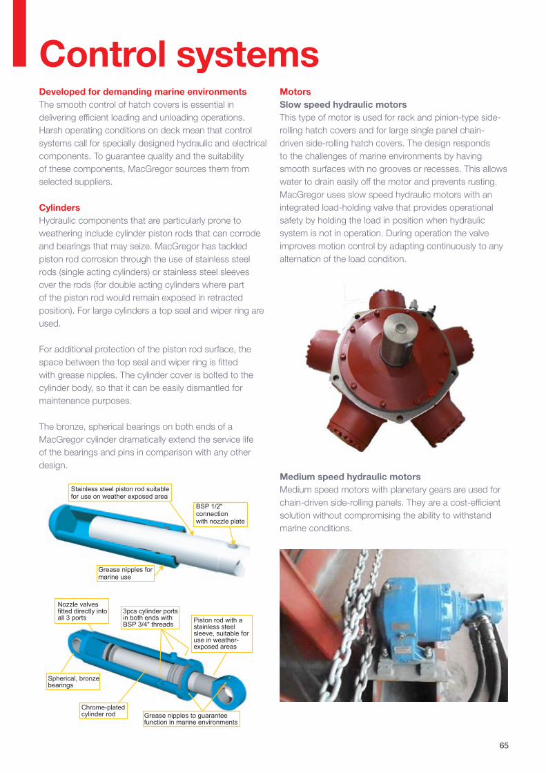
65
Relative movements between the hull and the hatch cover
Control systems Developed for demanding marine environmentsThe smooth control of hatch covers is essential in delivering efficient loading and unloading operations. Harsh operating conditions on deck mean that control systems call for specially designed hydraulic and electrical components. To guarantee quality and the suitability of these components, MacGregor sources them from selected suppliers.
CylindersHydraulic components that are particularly prone to weathering include cylinder piston rods that can corrode and bearings that may seize. MacGregor has tackled piston rod corrosion through the use of stainless steel rods (single acting cylinders) or stainless steel sleeves over the rods (for double acting cylinders where part of the piston rod would remain exposed in retracted position). For large cylinders a top seal and wiper ring are used.
For additional protection of the piston rod surface, the space between the top seal and wiper ring is fitted with grease nipples. The cylinder cover is bolted to the cylinder body, so that it can be easily dismantled for maintenance purposes.
The bronze, spherical bearings on both ends of a MacGregor cylinder dramatically extend the service life of the bearings and pins in comparison with any other design.
MotorsSlow speed hydraulic motorsThis type of motor is used for rack and pinion-type side-rolling hatch covers and for large single panel chain-driven side-rolling hatch covers. The design responds to the challenges of marine environments by having smooth surfaces with no grooves or recesses. This allows water to drain easily off the motor and prevents rusting. MacGregor uses slow speed hydraulic motors with an integrated load-holding valve that provides operational safety by holding the load in position when hydraulic system is not in operation. During operation the valve improves motion control by adapting continuously to any alternation of the load condition.
Stainless steel piston rod suitablefor use on weather exposed area
Grease nipples for marine use
BSP 1/2"connectionwith nozzle plate
Nozzle valves fitted directly into all 3 ports
Spherical, bronze bearings
3pcs cylinder portsin both ends with BSP 3/4" threads Piston rod with a
stainless steel sleeve, suitable for use in weather-exposed areas
Chrome-plated cylinder rod Grease nipples to guarantee
function in marine environments
Medium speed hydraulic motorsMedium speed motors with planetary gears are used for chain-driven side-rolling panels. They are a cost-efficient solution without compromising the ability to withstand marine conditions.
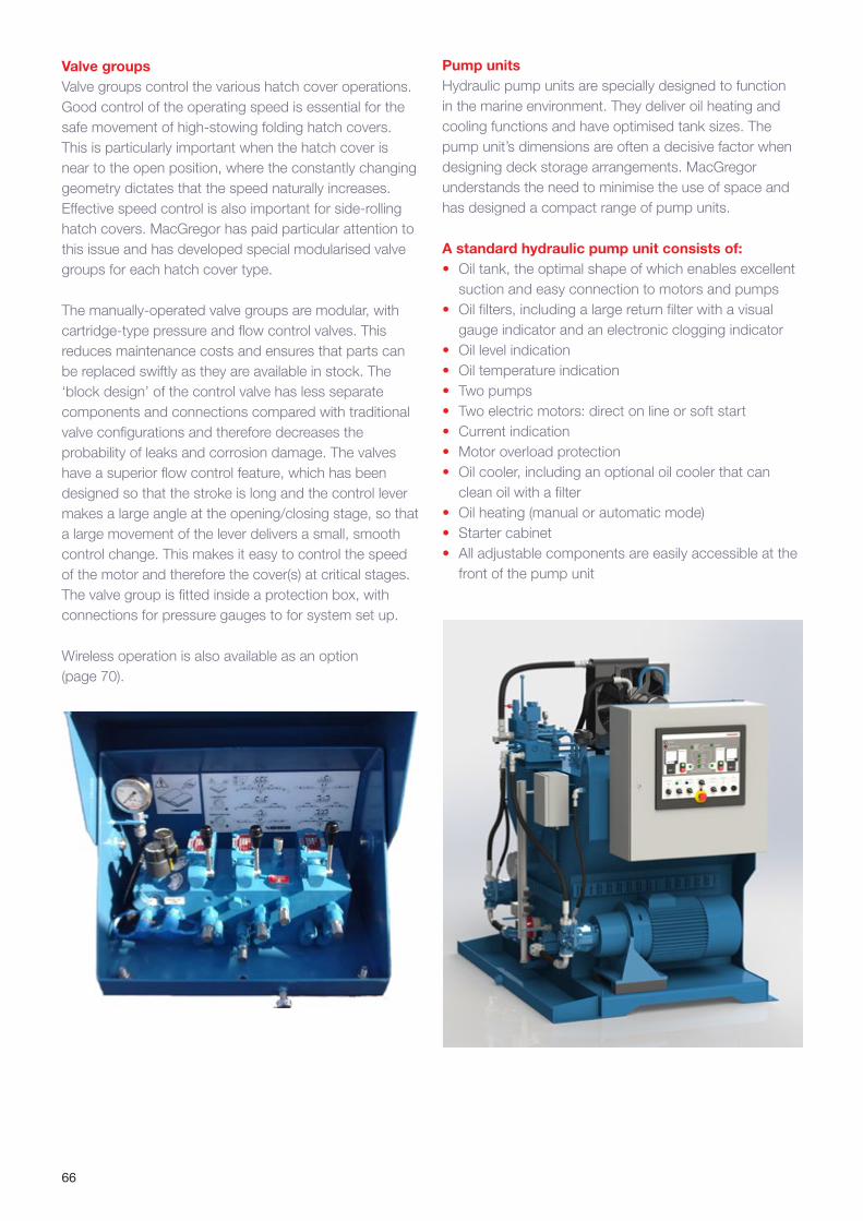
66
Valve groupsValve groups control the various hatch cover operations. Good control of the operating speed is essential for the safe movement of high-stowing folding hatch covers. This is particularly important when the hatch cover is near to the open position, where the constantly changing geometry dictates that the speed naturally increases. Effective speed control is also important for side-rolling hatch covers. MacGregor has paid particular attention to this issue and has developed special modularised valve groups for each hatch cover type.
The manually-operated valve groups are modular, with cartridge-type pressure and flow control valves. This reduces maintenance costs and ensures that parts can be replaced swiftly as they are available in stock. The ‘block design’ of the control valve has less separate components and connections compared with traditional valve configurations and therefore decreases the probability of leaks and corrosion damage. The valves have a superior flow control feature, which has been designed so that the stroke is long and the control lever makes a large angle at the opening/closing stage, so that a large movement of the lever delivers a small, smooth control change. This makes it easy to control the speed of the motor and therefore the cover(s) at critical stages. The valve group is fitted inside a protection box, with connections for pressure gauges to for system set up.
Wireless operation is also available as an option (page 70).
Pump unitsHydraulic pump units are specially designed to function in the marine environment. They deliver oil heating and cooling functions and have optimised tank sizes. The pump unit’s dimensions are often a decisive factor when designing deck storage arrangements. MacGregor understands the need to minimise the use of space and has designed a compact range of pump units.
A standard hydraulic pump unit consists of:• Oil tank, the optimal shape of which enables excellent
suction and easy connection to motors and pumps• Oil filters, including a large return filter with a visual
gauge indicator and an electronic clogging indicator• Oil level indication• Oil temperature indication• Two pumps• Two electric motors: direct on line or soft start • Current indication• Motor overload protection• Oil cooler, including an optional oil cooler that can
clean oil with a filter • Oil heating (manual or automatic mode)• Starter cabinet• All adjustable components are easily accessible at the
front of the pump unit
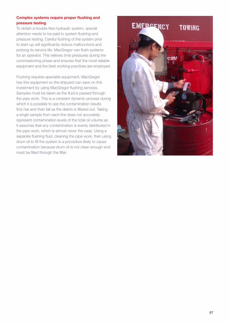
67
Complex systems require proper flushing and pressure testingTo obtain a trouble-free hydraulic system, special attention needs to be paid to system flushing and pressure testing. Careful flushing of the system prior to start-up will significantly reduce malfunctions and prolong its service life. MacGregor can flush systems for an operator. This relieves time pressures during the commissioning phase and ensures that the most reliable equipment and the best working practices are employed.
Flushing requires specialist equipment. MacGregor has this equipment so the shipyard can save on this investment by using MacGregor flushing services. Samples must be taken as the fluid is passed through the pipe work. This is a constant dynamic process during which it is possible to see the contamination results first rise and then fall as the debris is filtered out. Taking a single sample from each line does not accurately represent contamination levels of the total oil volume as it assumes that any contamination is evenly distributed in the pipe work, which is almost never the case. Using a separate flushing fluid, cleaning the pipe work, then using drum oil to fill the system is a procedure likely to cause contamination because drum oil is not clean enough and must be filled through the filter.

68
Soft starter: a new electric starter cabinetMacGregor’s new electric starter cabinet for hydraulic hatch cover power units used on bulk carriers and general cargo ships features an intelligent ‘soft start’ function that avoids starting current peaks. The new starter, which also reduces stresses on mechanical and hydraulic components, is intended both for newbuild applications and for retrofitting to existing hatch cover operating systems.
The starter can be built to meet your specific needs. The soft start method replaces the Star Delta starting method. It reduces the starting peak, limiting the stress on mechanical and hydraulic components. The new MacGregor soft starter provides the soft starting option for low-power motors where it is not available as a standard feature. There are five basic variants, the first one of which is Direct On Line with soft starter as an option. The other four options include soft start as a standard function.
Safe and simple to select and operate The new starter cabinet has a clear, user-friendly operating panel for safe and easy operation. A range of optional features allows easy selection of the most appropriate starter configuration. The new MacGregor soft starter has five basic variants according to motor size, along with five functional options depending on the control system requirements. The system is based on a 24V DC control voltage, which is safer when compared with 230V AC, for example. In addition, frequency variants for 50 or 60Hz supply are not required. The new starter has a data logging facility, which is accessible to MacGregor engineers for service, feedback and diagnostic purposes.
Whatever the size of the motor and whether it is ease and safety of operations, energy efficiency or time savings that are the key requirements, it is now possible to pick the right combination for each ship’s needs. Some examples include:
• F1 Oil cooler: Oil cooler is normally chosen as part of the system. It can also be used for circulating the oil in the tank when the oil heating is in operation and for off-line filtering.
• F2 Confirmation button: An alternative to the emergency stop button. The button is located on the opposite side of the hatchway to the control stand. It must be pressed and held down throughout the entire operation, ensuring that two people are involved, thereby promoting safe operational practice. When the confirmation button is released, the operating pressure instantly drops to zero, leaving the power unit running in standby mode. The hydraulic system is pressurised only when the button is held down. This reduces the number of start/stop sequences, which slows down the oil’s chemical aging process and prolongs the components’ working life. It is also energy efficient, because the motors only work at full capacity during hatch operation.
• F3 Remote control: One remote control unit outside hydraulic pump unit room or alternatively one remote control unit inside each control stand allow the operator to start up and shut down the hydraulic pump unit remotely. This reduces idling and can save a lot of time when the pump unit is situated well away from the control stands.
• F4 Pressure filter: The pressure filter is located in the supply line from the hydraulic pump unit; it improves oil filltration.
• F5 Supply line pressure indication: Indicates the low/high pressure in the supply line starting at the hydraulic pump unit. Usually chosen by class requirement or if pressure indication is needed.
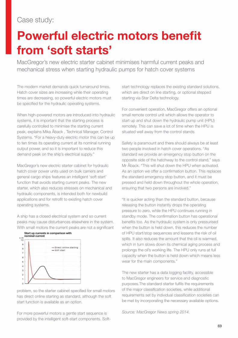
69
start technology replaces the existing standard solutions, which are direct on line starting, or optional stepped starting via Star Delta technology.
For convenient operation, MacGregor offers an optional small remote control unit which allows the operator to start up and shut down the hydraulic pump unit (HPU) remotely. This can save a lot of time when the HPU is situated well away from the control stands.
Safety is paramount and there should always be at least two people involved in hatch cover operations. “As standard we provide an emergency stop button on the opposite side of the hatchway to the control stand,” says Mr Åback. “This will shut down the HPU when activated. As an option we offer a confirmation button. This replaces the standard emergency stop button, and it must be pressed and held down throughout the whole operation, ensuring that two persons are involved.”
“It is quicker acting than the standard button, because releasing the button instantly drops the operating pressure to zero, while the HPU continues running in standby mode. The confirmation button has operational benefits too. As the hydraulic system is only pressurised when the button is held down, this reduces the number of HPU start/stop sequences and lessens the risk of oil spills. It also reduces the amount that the oil is warmed, which in turn slows down its chemical aging process and prolongs the oil’s working life. The HPU only runs at full capacity when the button is held down which means less wear for the main components.”
The new starter has a data logging facility, accessible to MacGregor engineers for service and diagnostic purposes.The standard starter fulfils the requirements of the major classification societies, while additional requirements set by individual classification societies can be met by incorporating the necessary available options.
Source: MacGregor News spring 2014.
Powerful electric motors benefit from ‘soft starts’
The modern market demands quick turnaround times. Hatch cover sizes are increasing while their operating times are decreasing, so powerful electric motors must be specified for the hydraulic operating systems.
When high-powered motors are introduced into hydraulic systems, it is important that the starting process is carefully controlled to minimise the starting current peak, explains Mika Åback , Technical Manager, Control Systems. “For a heavy-duty electric motor this can be up to ten times its operating current at its nominal running output power, and so it is important to reduce this demand peak on the ship’s electrical supply.”
MacGregor’s new electric starter cabinet for hydraulic hatch cover power units used on bulk carriers and general cargo ships features an intelligent ‘soft start’ function that avoids starting current peaks. The new starter, which also reduces stresses on mechanical and hydraulic components, is intended both for newbuild applications and for retrofit to existing hatch cover operating systems.
A ship has a closed electrical system and so current peaks may cause disturbances elsewhere in the system. With small motors the current peaks are not a significant
MacGregor’s new electric starter cabinet minimises harmful current peaks and mechanical stress when starting hydraulic pumps for hatch cover systems
Case study:
problem, so the starter cabinet specified for small motors has direct online starting as standard, although the soft start function is available as an option.
For more powerful motors a gentle start sequence is provided by the intelligent soft-start components. Soft-
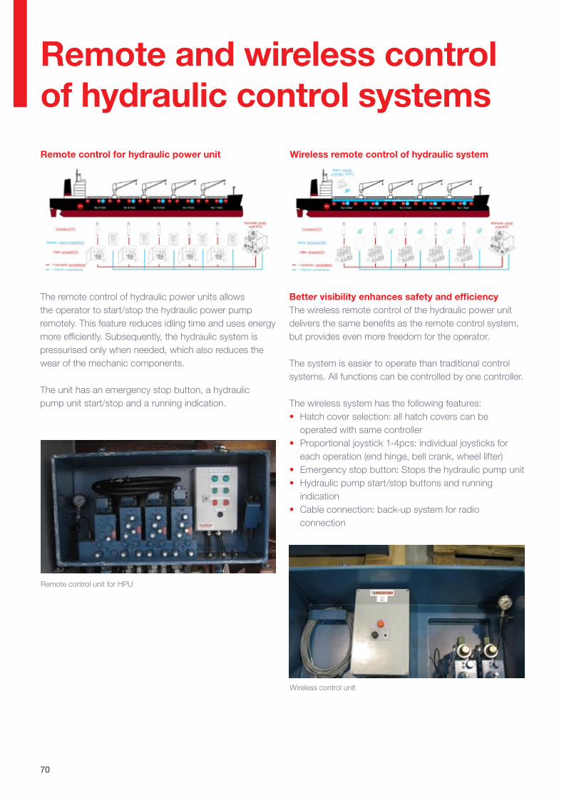
70
Wireless remote control of hydraulic system
Remote and wireless control of hydraulic control systemsRemote control for hydraulic power unit
Remote control unit for HPU
Wireless control unit
The remote control of hydraulic power units allows the operator to start/stop the hydraulic power pump remotely. This feature reduces idling time and uses energy more efficiently. Subsequently, the hydraulic system is pressurised only when needed, which also reduces the wear of the mechanic components.
The unit has an emergency stop button, a hydraulic pump unit start/stop and a running indication.
Better visibility enhances safety and efficiencyThe wireless remote control of the hydraulic power unit delivers the same benefits as the remote control system, but provides even more freedom for the operator.
The system is easier to operate than traditional control systems. All functions can be controlled by one controller.
The wireless system has the following features:• Hatch cover selection: all hatch covers can be
operated with same controller• Proportional joystick 1-4pcs: individual joysticks for
each operation (end hinge, bell crank, wheel lifter)• Emergency stop button: Stops the hydraulic pump unit• Hydraulic pump start/stop buttons and running
indication• Cable connection: back-up system for radio
connection
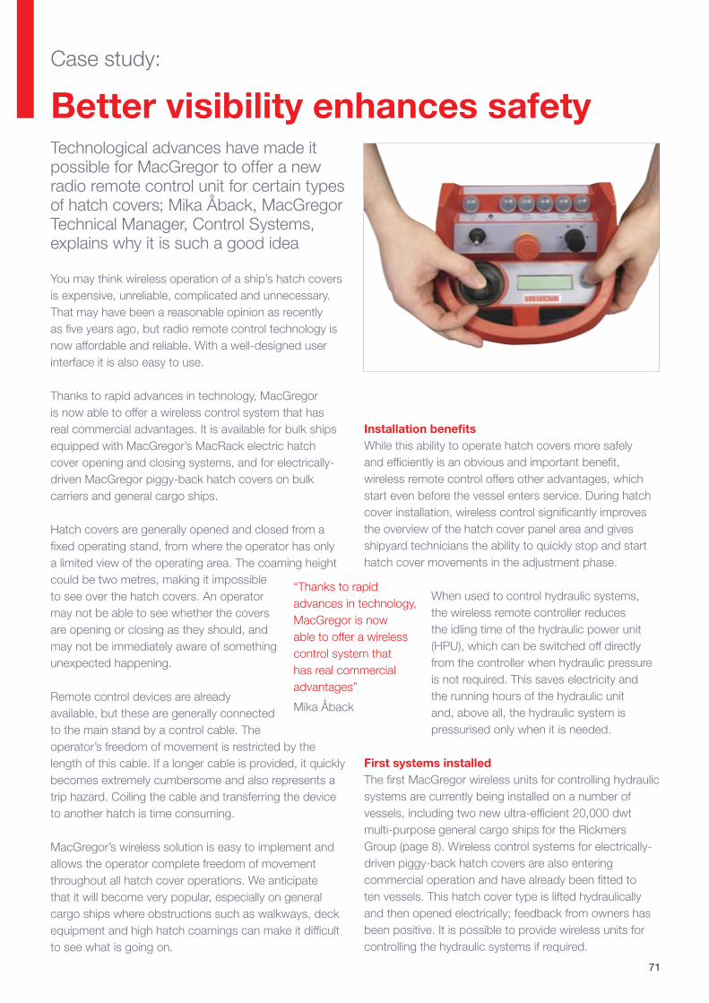
71
Technological advances have made it possible for MacGregor to offer a new radio remote control unit for certain types of hatch covers; Mika Åback, MacGregor Technical Manager, Control Systems, explains why it is such a good idea
Better visibility enhances safety
You may think wireless operation of a ship’s hatch covers is expensive, unreliable, complicated and unnecessary. That may have been a reasonable opinion as recently as five years ago, but radio remote control technology is now affordable and reliable. With a well-designed user interface it is also easy to use.
Thanks to rapid advances in technology, MacGregor is now able to offer a wireless control system that has real commercial advantages. It is available for bulk ships equipped with MacGregor’s MacRack electric hatch cover opening and closing systems, and for electrically-driven MacGregor piggy-back hatch covers on bulk carriers and general cargo ships.
Hatch covers are generally opened and closed from a fixed operating stand, from where the operator has only a limited view of the operating area. The coaming height could be two metres, making it impossible to see over the hatch covers. An operator may not be able to see whether the covers are opening or closing as they should, and may not be immediately aware of something unexpected happening.
Remote control devices are already available, but these are generally connected to the main stand by a control cable. The operator’s freedom of movement is restricted by the length of this cable. If a longer cable is provided, it quickly becomes extremely cumbersome and also represents a trip hazard. Coiling the cable and transferring the device to another hatch is time consuming.
MacGregor’s wireless solution is easy to implement and allows the operator complete freedom of movement throughout all hatch cover operations. We anticipate that it will become very popular, especially on general cargo ships where obstructions such as walkways, deck equipment and high hatch coamings can make it difficult to see what is going on.
Installation benefitsWhile this ability to operate hatch covers more safely and efficiently is an obvious and important benefit, wireless remote control offers other advantages, which start even before the vessel enters service. During hatch cover installation, wireless control significantly improves the overview of the hatch cover panel area and gives shipyard technicians the ability to quickly stop and start hatch cover movements in the adjustment phase.
When used to control hydraulic systems, the wireless remote controller reduces the idling time of the hydraulic power unit (HPU), which can be switched off directly from the controller when hydraulic pressure is not required. This saves electricity and the running hours of the hydraulic unit and, above all, the hydraulic system is pressurised only when it is needed.
First systems installedThe first MacGregor wireless units for controlling hydraulic systems are currently being installed on a number of vessels, including two new ultra-efficient 20,000 dwt multi-purpose general cargo ships for the Rickmers Group (page 8). Wireless control systems for electrically-driven piggy-back hatch covers are also entering commercial operation and have already been fitted to ten vessels. This hatch cover type is lifted hydraulically and then opened electrically; feedback from owners has been positive. It is possible to provide wireless units for controlling the hydraulic systems if required.
“Thanks to rapid advances in technology, MacGregor is now able to offer a wireless control system that has real commercial advantages”
Mika Åback
Case study:
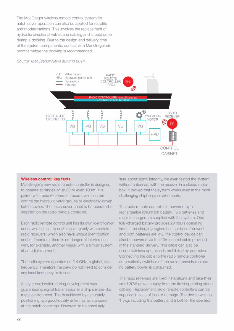
72
VG
The MacGregor wireless remote control system for hatch cover operation can also be applied for retrofits and modernisations. This involves the replacement of hydraulic directional valves and cabling and is best done during a docking. Due to the design and delivery time of the system components, contact with MacGregor six months before the docking is recommended.
Wireless control: key factsMacGregor’s new radio remote controller is designed to operate at ranges of up 50 or even 100m. It is paired with radio receivers on board, which in turn control the hydraulic valve groups or electrically-driven hatch covers. The hatch cover panel to be operated is selected on the radio remote controller.
Each radio remote control unit has its own identification code, which is set to enable pairing only with certain radio receivers, which also have unique identification codes. Therefore, there is no danger of interference with, for example, another vessel with a similar system at an adjoining berth.
The radio system operates on 2.4 GHz, a global, free frequency. Therefore the crew do not need to consider any local frequency limitations.
A key consideration during development was guaranteeing signal transmission in a ship’s maze-like metal environment. This is achieved by accurately positioning two good-quality antennas as standard at the hatch coamings. However, to be absolutely
sure about signal integrity, we even tested the system without antennas, with the receiver in a closed metal box. It proved that the system works even in the most challenging shipboard environments.
The radio remote controller is powered by a rechargeable lithium ion battery. Two batteries and a quick charger are supplied with the system. One fully-charged battery provides 20 hours operating time. If the charging regime has not been followed and both batteries are low, the control device can also be powered via the 10m control cable provided in the standard delivery. This cable can also be used if wireless operation is prohibited by port rules. Connecting the cable to the radio remote controller automatically switches off the radio transmission and no battery power is consumed.
The radio receivers are fixed installations and take their small 30W power supply from the fixed operating stand cabling. Replacement radio remote controllers can be supplied in case of loss or damage. The device weighs 1.5kg, including the battery and a belt for the operator.
VGVGVGVG
HPU
RADIO CONTROLLER’s operating range
VG Valve groupHPU Hydraulic pump unit Hydraulics Electrics
CYLINDERS AND MOTOR
RRC
RR
HYDRAULICMOTOR
HYDRAULICCYLINDERS
RADIO RECEIVER
RADIO REMOTE
CONTROLLER(RRC)
Source: MacGregor News autumn 2014.
CONTROL CABINET
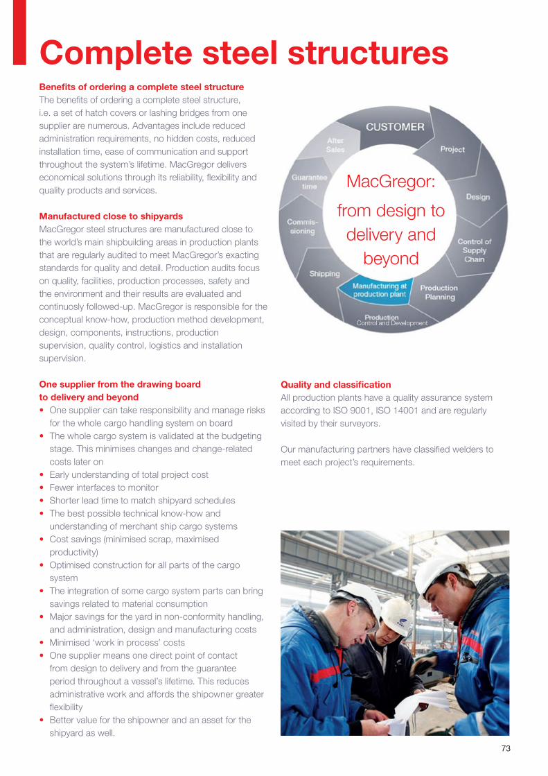
73
Complete steel structuresBenefits of ordering a complete steel structureThe benefits of ordering a complete steel structure, i.e. a set of hatch covers or lashing bridges from one supplier are numerous. Advantages include reduced administration requirements, no hidden costs, reduced installation time, ease of communication and support throughout the system’s lifetime. MacGregor delivers economical solutions through its reliability, flexibility and quality products and services.
Manufactured close to shipyardsMacGregor steel structures are manufactured close to the world’s main shipbuilding areas in production plants that are regularly audited to meet MacGregor’s exacting standards for quality and detail. Production audits focus on quality, facilities, production processes, safety and the environment and their results are evaluated and continuosly followed-up. MacGregor is responsible for the conceptual know-how, production method development, design, components, instructions, production supervision, quality control, logistics and installation supervision.
One supplier from the drawing board to delivery and beyond• One supplier can take responsibility and manage risks
for the whole cargo handling system on board• The whole cargo system is validated at the budgeting
stage. This minimises changes and change-related costs later on
• Early understanding of total project cost• Fewer interfaces to monitor• Shorter lead time to match shipyard schedules• The best possible technical know-how and
understanding of merchant ship cargo systems• Cost savings (minimised scrap, maximised
productivity)• Optimised construction for all parts of the cargo
system• The integration of some cargo system parts can bring
savings related to material consumption• Major savings for the yard in non-conformity handling,
and administration, design and manufacturing costs• Minimised ‘work in process’ costs• One supplier means one direct point of contact
from design to delivery and from the guarantee period throughout a vessel’s lifetime. This reduces administrative work and affords the shipowner greater flexibility
• Better value for the shipowner and an asset for the shipyard as well.
MacGregor:
from design to delivery and
beyond
Quality and classificationAll production plants have a quality assurance system according to ISO 9001, ISO 14001 and are regularly visited by their surveyors.
Our manufacturing partners have classified welders to meet each project’s requirements.
Control and Development
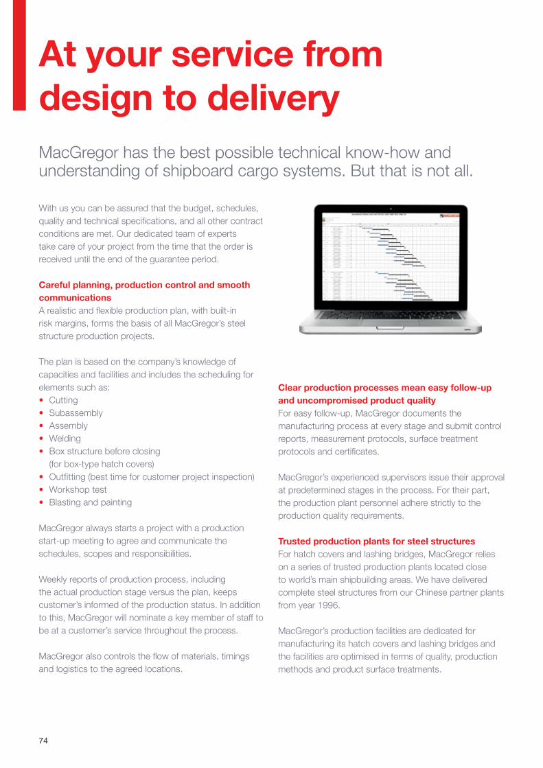
74
MacGregor has the best possible technical know-how and understanding of shipboard cargo systems. But that is not all.
At your service from design to delivery
With us you can be assured that the budget, schedules, quality and technical specifications, and all other contract conditions are met. Our dedicated team of experts take care of your project from the time that the order is received until the end of the guarantee period.
Careful planning, production control and smooth communicationsA realistic and flexible production plan, with built-in risk margins, forms the basis of all MacGregor’s steel structure production projects.
The plan is based on the company’s knowledge of capacities and facilities and includes the scheduling for elements such as:• Cutting• Subassembly• Assembly• Welding• Box structure before closing
(for box-type hatch covers)• Outfitting (best time for customer project inspection)• Workshop test• Blasting and painting
MacGregor always starts a project with a production start-up meeting to agree and communicate the schedules, scopes and responsibilities.
Weekly reports of production process, including the actual production stage versus the plan, keeps customer’s informed of the production status. In addition to this, MacGregor will nominate a key member of staff to be at a customer’s service throughout the process.
MacGregor also controls the flow of materials, timings and logistics to the agreed locations.
Clear production processes mean easy follow-up and uncompromised product qualityFor easy follow-up, MacGregor documents the manufacturing process at every stage and submit control reports, measurement protocols, surface treatment protocols and certificates.
MacGregor’s experienced supervisors issue their approval at predetermined stages in the process. For their part, the production plant personnel adhere strictly to the production quality requirements.
Trusted production plants for steel structuresFor hatch covers and lashing bridges, MacGregor relies on a series of trusted production plants located close to world’s main shipbuilding areas. We have delivered complete steel structures from our Chinese partner plants from year 1996.
MacGregor’s production facilities are dedicated for manufacturing its hatch covers and lashing bridges and the facilities are optimised in terms of quality, production methods and product surface treatments.
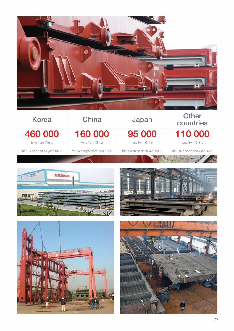
75
Korea China Japan Other countries
460 000 160 000 95 000 110 000tons from China tons from China tons from China tons from China
for 495 ships since year 1997f for 290 ships since year 1996 for 120 ships since year 2004 for 210 ships since year 1998
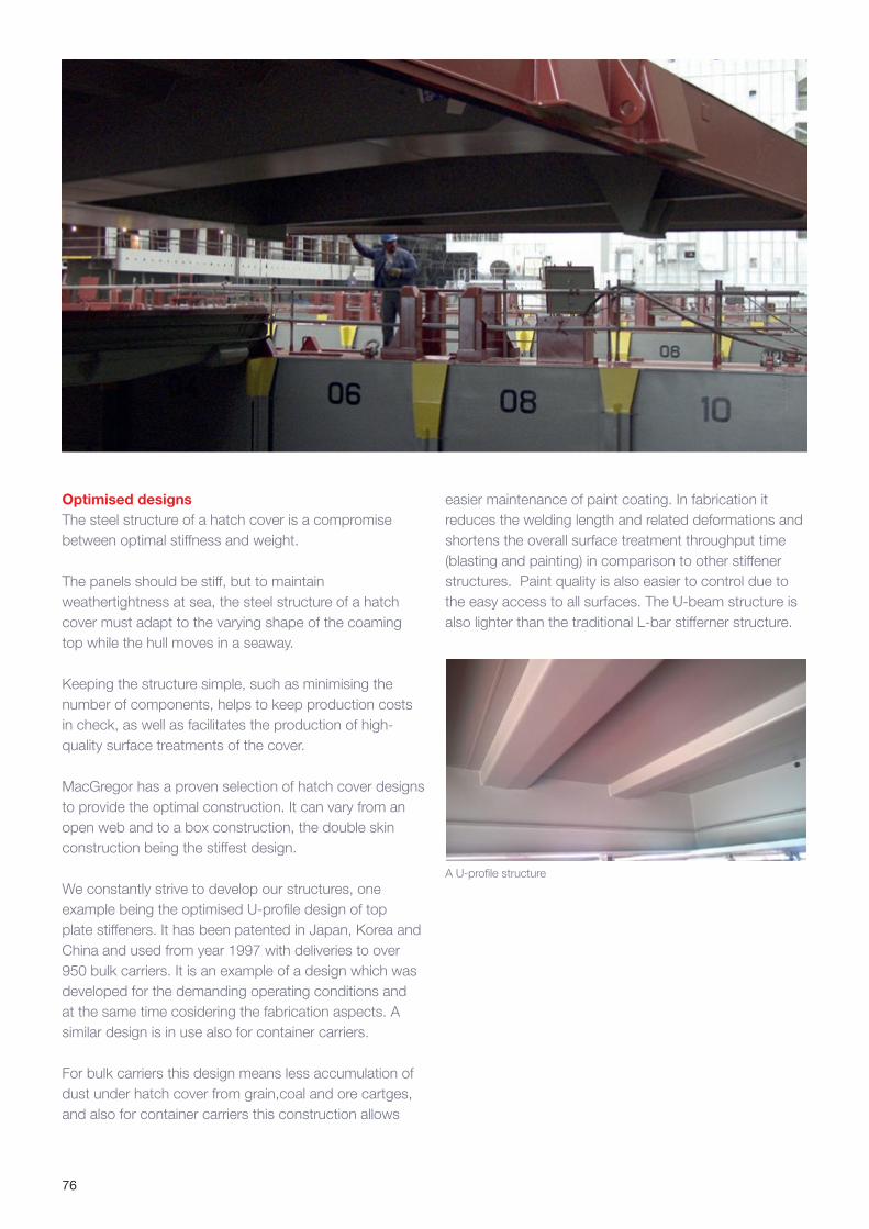
Optimised designsThe steel structure of a hatch cover is a compromise between optimal stiffness and weight.
The panels should be stiff, but to maintain weathertightness at sea, the steel structure of a hatch cover must adapt to the varying shape of the coaming top while the hull moves in a seaway.
Keeping the structure simple, such as minimising the number of components, helps to keep production costs in check, as well as facilitates the production of high-quality surface treatments of the cover.
MacGregor has a proven selection of hatch cover designs to provide the optimal construction. It can vary from an open web and to a box construction, the double skin construction being the stiffest design.
We constantly strive to develop our structures, one example being the optimised U-profile design of top plate stiffeners. It has been patented in Japan, Korea and China and used from year 1997 with deliveries to over 950 bulk carriers. It is an example of a design which was developed for the demanding operating conditions and at the same time cosidering the fabrication aspects. A similar design is in use also for container carriers.
For bulk carriers this design means less accumulation of dust under hatch cover from grain,coal and ore cartges, and also for container carriers this construction allows
easier maintenance of paint coating. In fabrication it reduces the welding length and related deformations and shortens the overall surface treatment throughput time (blasting and painting) in comparison to other stiffener structures. Paint quality is also easier to control due to the easy access to all surfaces. The U-beam structure is also lighter than the traditional L-bar stifferner structure.
A U-profile structure
76

Hatch cover and lashing bridge transport calls for specialist knowledge
MacGregor’s mission is to deliver steel structures on time and in perfect condition. For this, the company employs specialised lashings, re-usable steel transport supports and other specifically-designed devices, which MacGregor has developed for the safe loading and transportation of hatch covers.
MacGregor considers the transportation of the end product at the product design phase to support smooth deliveries. The transportation and delivery logistics of steel structures can easily become a costly process, but with MacGregor’s expertise these costs can be kept under control by carefully planning the right lashings, timings, loading locations and delivery conditions. This minimises crane hours and insurance arrangements.
Not only the hardware matters when MacGregor takes care of the transport on a ‘delivery at place’ basis, the hatch covers or lashing bridges are safe from both an insurance and delivery-condition perspective. MacGregor’s advanced transportation capabilities are based on 20 years experience of demanding steel structure deliveries.
The vessels used for transportation are selected with great care and before the delivery voyage, the insurance company approves both the stowage and lashing arrangements prior to departure.
77
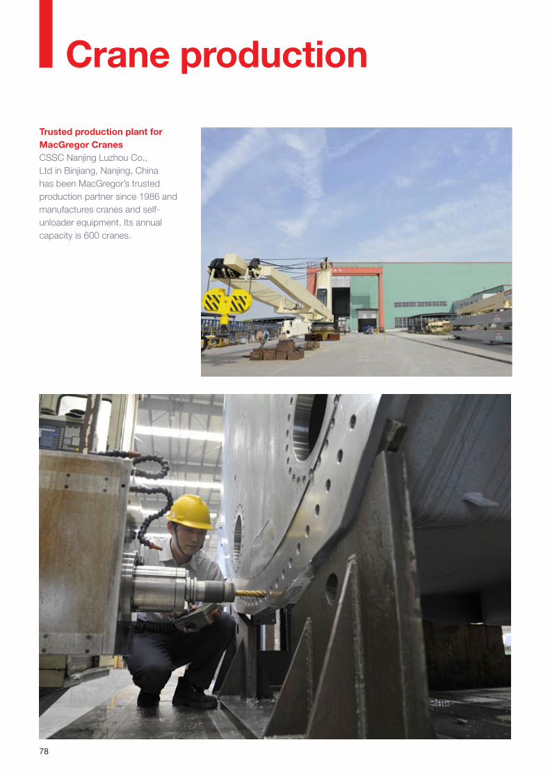
78
Crane production
Trusted production plant for MacGregor CranesCSSC Nanjing Luzhou Co., Ltd in Binjiang, Nanjing, China has been MacGregor’s trusted production partner since 1986 and manufactures cranes and self-unloader equipment. Its annual capacity is 600 cranes.
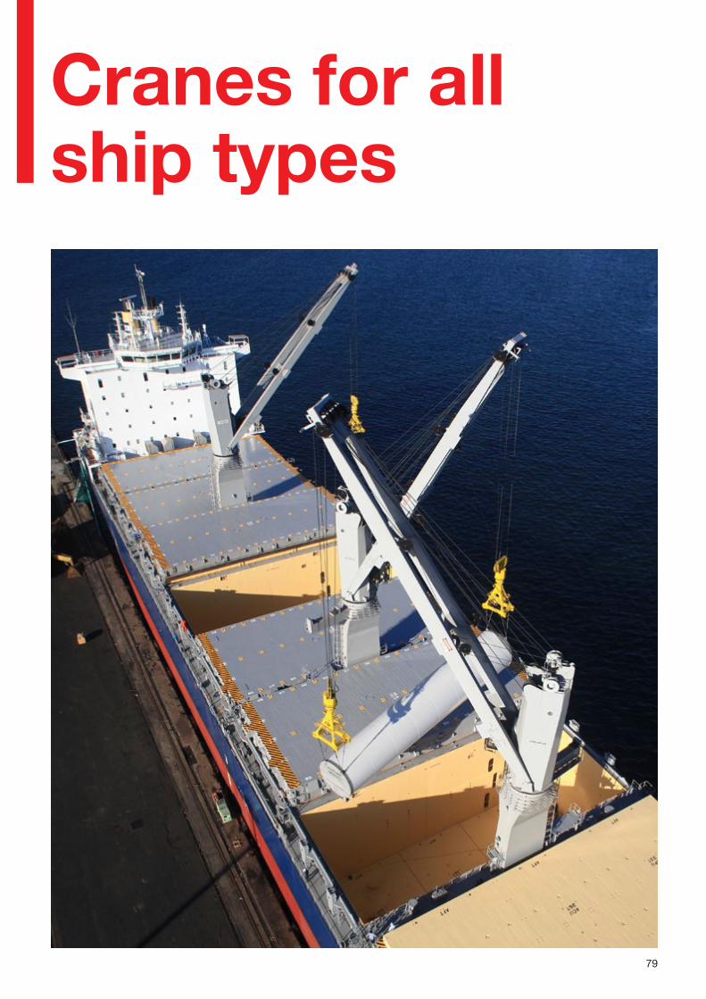
79
Cranes for all ship types
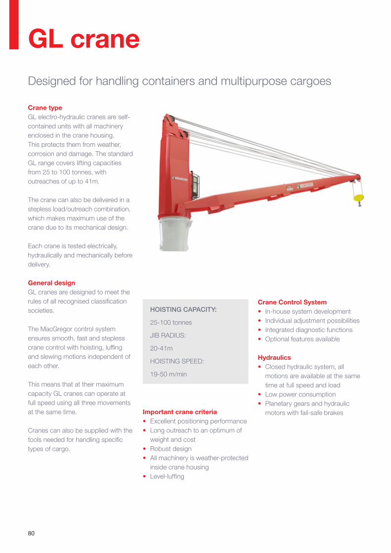
80
GL craneDesigned for handling containers and multipurpose cargoes
HOISTING CAPACITY:
25-100 tonnes
JIB RADIUS:
20-41m
HOISTING SPEED:
19-50 m/min
Crane typeGL electro-hydraulic cranes are self-contained units with all machinery enclosed in the crane housing. This protects them from weather, corrosion and damage. The standard GL range covers lifting capacities from 25 to 100 tonnes, with outreaches of up to 41m.
The crane can also be delivered in a stepless load/outreach combination, which makes maximum use of the crane due to its mechanical design.
Each crane is tested electrically, hydraulically and mechanically before delivery.
General designGL cranes are designed to meet the rules of all recognised classification societies.
The MacGregor control system ensures smooth, fast and stepless crane control with hoisting, luffing and slewing motions independent of each other.
This means that at their maximum capacity GL cranes can operate at full speed using all three movements at the same time.
Cranes can also be supplied with the tools needed for handling specific types of cargo.
Important crane criteria• Excellent positioning performance• Long outreach to an optimum of
weight and cost• Robust design• All machinery is weather-protected
inside crane housing• Level-luffing
Crane Control System• In-house system development• Individual adjustment possibilities• Integrated diagnostic functions• Optional features available
Hydraulics• Closed hydraulic system, all
motions are available at the same time at full speed and load
• Low power consumption• Planetary gears and hydraulic
motors with fail-safe brakes
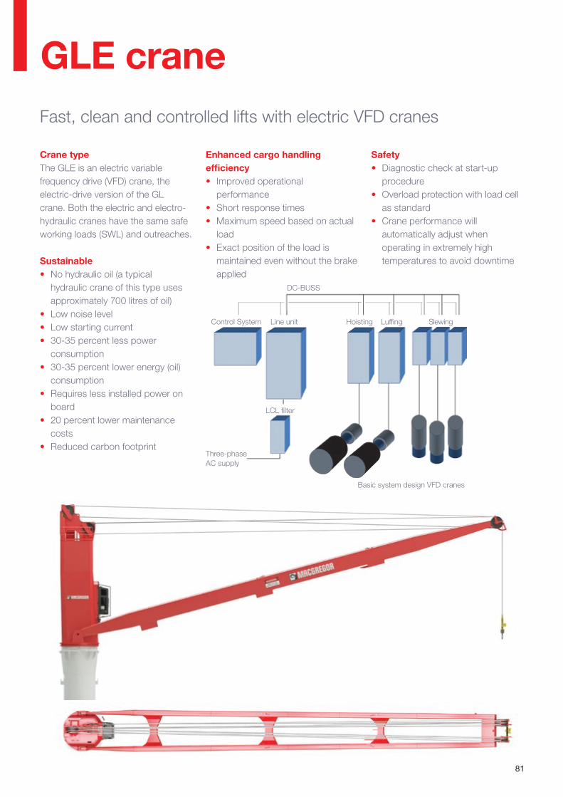
81
Enhanced cargo handling efficiency• Improved operational
performance• Short response times • Maximum speed based on actual
load • Exact position of the load is
maintained even without the brake applied
GLE craneFast, clean and controlled lifts with electric VFD cranes
Crane typeThe GLE is an electric variable frequency drive (VFD) crane, the electric-drive version of the GL crane. Both the electric and electro-hydraulic cranes have the same safe working loads (SWL) and outreaches.
Sustainable• No hydraulic oil (a typical
hydraulic crane of this type uses approximately 700 litres of oil)
• Low noise level• Low starting current• 30-35 percent less power
consumption• 30-35 percent lower energy (oil)
consumption• Requires less installed power on
board • 20 percent lower maintenance
costs• Reduced carbon footprint
Safety• Diagnostic check at start-up
procedure• Overload protection with load cell
as standard• Crane performance will
automatically adjust when operating in extremely high temperatures to avoid downtime
Basic system design VFD cranes
DC-BUSS
Control System
Three-phase AC supply
Line unit
LCL filter
Hoisting Luffing Slewing
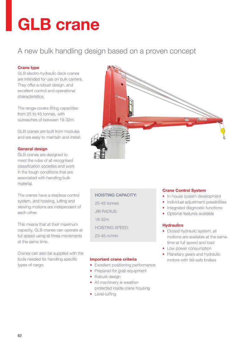
82
GLB craneA new bulk handling design based on a proven concept
Crane type GLB electro-hydraulic deck cranes are intended for use on bulk carriers. They offer a robust design, and excellent control and operational characteristics.
The range covers lifting capacities from 25 to 45 tonnes, with outreaches of between 18-32m.
GLB cranes are built from modules and are easy to maintain and install.
General design GLB cranes are designed to meet the rules of all recognised classification societies and work in the tough conditions that are associated with handling bulk material.
The cranes have a stepless control system, and hoisting, luffing and slewing motions are independent of each other.
This means that at their maximum capacity, GLB cranes can operate at full speed using all three movements at the same time.
Cranes can also be supplied with the tools needed for handling specific types of cargo.
HOISTING CAPACITY:
25-45 tonnes
JIB RADIUS:
18-32m
HOISTING SPEED:
23-45 m/min
Important crane criteria • Excellent positioning performance• Prepared for grab equipment• Robust design• All machinery is weather-
protected inside crane housing• Level-luffing
Crane Control System• In-house system development• Individual adjustment possibilities• Integrated diagnostic functions• Optional features available
Hydraulics• Closed hydraulic system, all
motions are available at the same time at full speed and load
• Low power consumption• Planetary gears and hydraulic
motors with fail-safe brakes

83
GLBE craneFast, clean and controlled lifts with electric VFD cranes
Enhanced cargo handling efficiency• Improved operational
performance• Short response times • Maximum speed based on actual
load • Exact position of the load is
maintained even without the brake applied
Crane typeThe GLBE is a electric variable requency drive (VFD) crane, the electric-drive version of the GLB crane. Both the electric and electro-hydraulic cranes have the same safe working loads (SWL) and outreaches.
Sustainable• No hydraulic oil (a typical
hydraulic crane of this type uses approximately 500 litres of oil)
• Low noise levels• Low starting current• 30-35 percent less power
consumption• 30-35 percent lower energy (oil)
consumption• Requires less installed power on
board • 20 percent lower maintenance
costs• Reduced carbon footprint
Safety• Diagnostic check at start-up
procedure• Overload protection with load cell
as standard• Crane performance will
automatically adjust when operating in extremely high temperatures to avoid downtime
Basic system design VFD cranes
DC-BUSS
Control System
Three-phase AC supply
Line unit
LCL filter
Hoisting Luffing Slewing
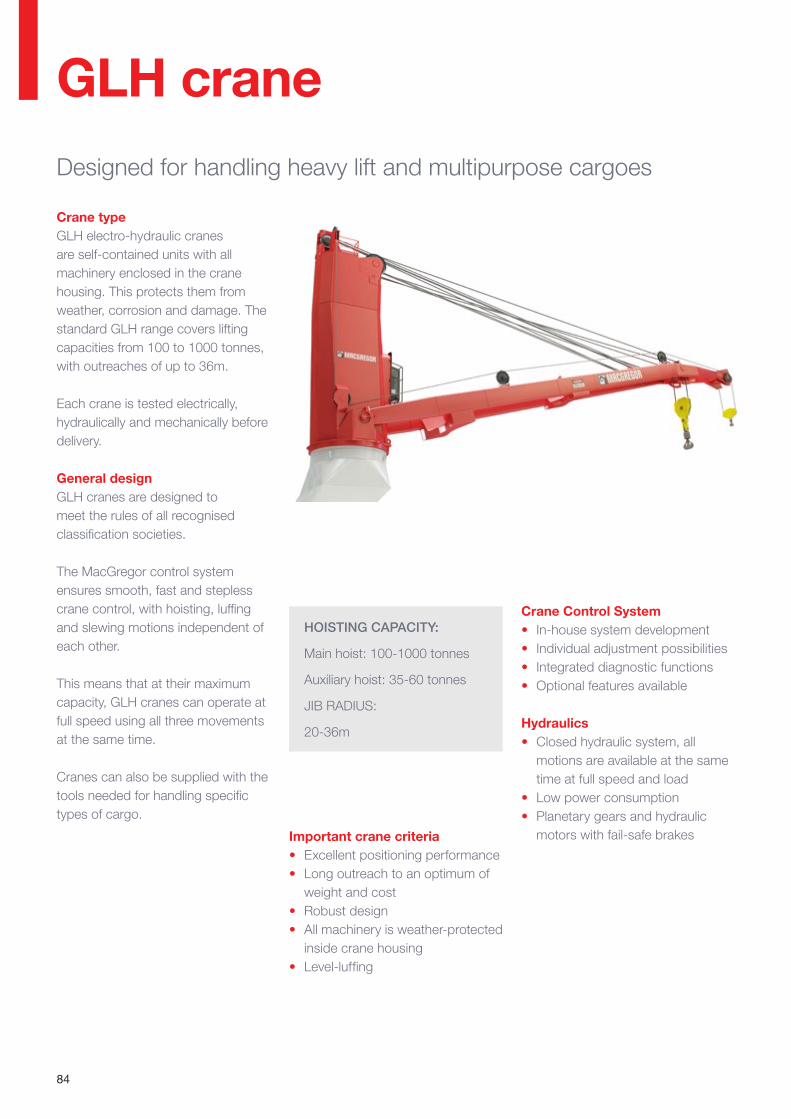
84
GLH craneDesigned for handling heavy lift and multipurpose cargoes
HOISTING CAPACITY:
Main hoist: 100-1000 tonnes
Auxiliary hoist: 35-60 tonnes
JIB RADIUS:
20-36m
Important crane criteria• Excellent positioning performance• Long outreach to an optimum of
weight and cost• Robust design• All machinery is weather-protected
inside crane housing• Level-luffing
Crane typeGLH electro-hydraulic cranes are self-contained units with all machinery enclosed in the crane housing. This protects them from weather, corrosion and damage. The standard GLH range covers lifting capacities from 100 to 1000 tonnes, with outreaches of up to 36m.
Each crane is tested electrically, hydraulically and mechanically before delivery.
General designGLH cranes are designed to meet the rules of all recognised classification societies.
The MacGregor control system ensures smooth, fast and stepless crane control, with hoisting, luffing and slewing motions independent of each other.
This means that at their maximum capacity, GLH cranes can operate at full speed using all three movements at the same time.
Cranes can also be supplied with the tools needed for handling specific types of cargo.
Crane Control System• In-house system development• Individual adjustment possibilities• Integrated diagnostic functions• Optional features available
Hydraulics• Closed hydraulic system, all
motions are available at the same time at full speed and load
• Low power consumption• Planetary gears and hydraulic
motors with fail-safe brakes
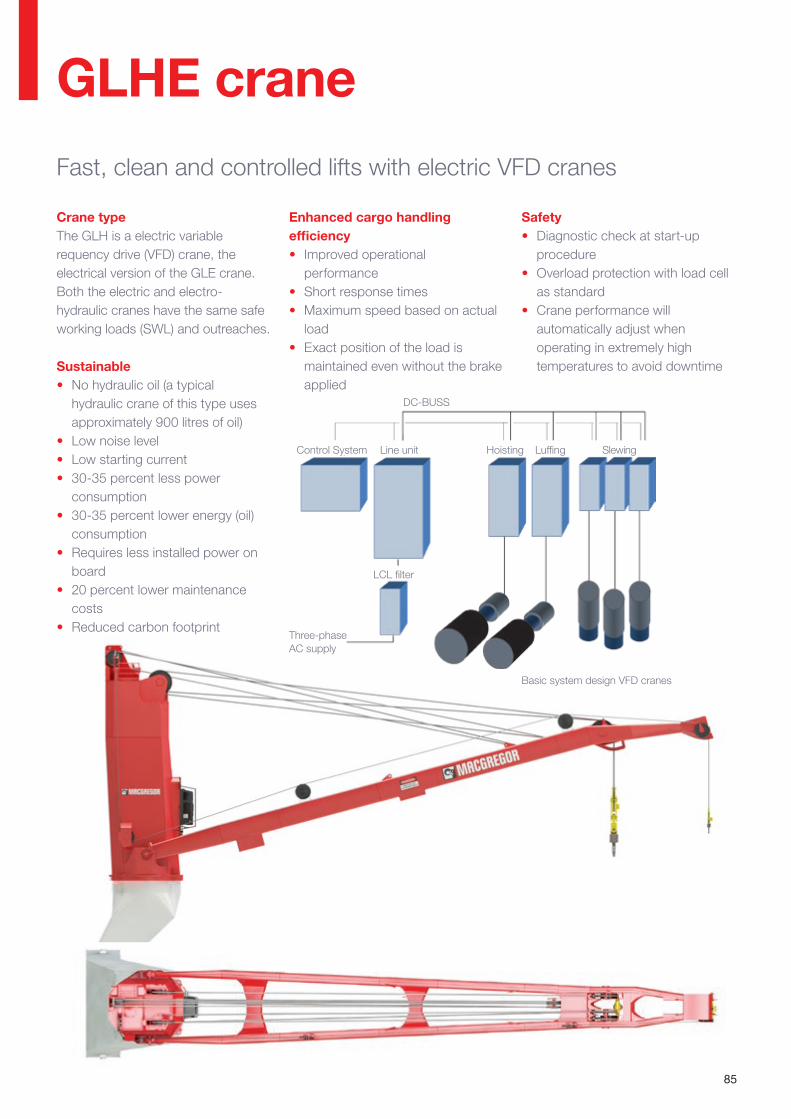
85
GLHE craneFast, clean and controlled lifts with electric VFD cranes
Enhanced cargo handling efficiency• Improved operational
performance• Short response times • Maximum speed based on actual
load • Exact position of the load is
maintained even without the brake applied
Crane typeThe GLH is a electric variable requency drive (VFD) crane, the electrical version of the GLE crane. Both the electric and electro-hydraulic cranes have the same safe working loads (SWL) and outreaches.
Sustainable• No hydraulic oil (a typical
hydraulic crane of this type uses approximately 900 litres of oil)
• Low noise level• Low starting current• 30-35 percent less power
consumption• 30-35 percent lower energy (oil)
consumption• Requires less installed power on
board • 20 percent lower maintenance
costs• Reduced carbon footprint
Safety• Diagnostic check at start-up
procedure• Overload protection with load cell
as standard• Crane performance will
automatically adjust when operating in extremely high temperatures to avoid downtime
Basic system design VFD cranes
DC-BUSS
Control System
Three-phase AC supply
Line unit
LCL filter
Hoisting Luffing Slewing
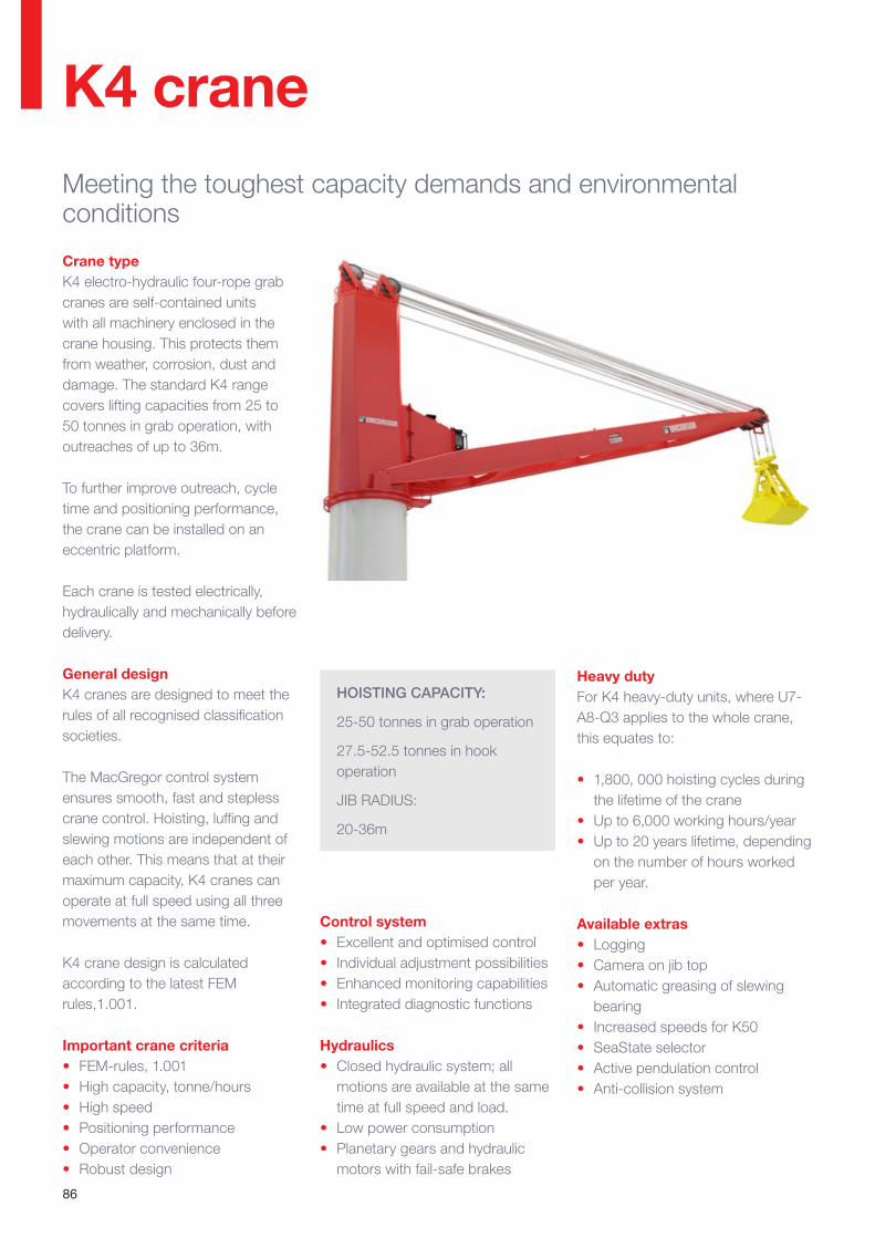
86
K4 craneMeeting the toughest capacity demands and environmental conditions
HOISTING CAPACITY:
25-50 tonnes in grab operation
27.5-52.5 tonnes in hook operation
JIB RADIUS:
20-36m
Crane type K4 electro-hydraulic four-rope grab cranes are self-contained units with all machinery enclosed in the crane housing. This protects them from weather, corrosion, dust and damage. The standard K4 range covers lifting capacities from 25 to 50 tonnes in grab operation, with outreaches of up to 36m.
To further improve outreach, cycle time and positioning performance, the crane can be installed on an eccentric platform.
Each crane is tested electrically, hydraulically and mechanically before delivery.
General design K4 cranes are designed to meet the rules of all recognised classification societies.
The MacGregor control system ensures smooth, fast and stepless crane control. Hoisting, luffing and slewing motions are independent of each other. This means that at their maximum capacity, K4 cranes can operate at full speed using all three movements at the same time.
K4 crane design is calculated according to the latest FEM rules,1.001.
Important crane criteria • FEM-rules, 1.001• High capacity, tonne/hours• High speed• Positioning performance• Operator convenience• Robust design
Control system • Excellent and optimised control• Individual adjustment possibilities• Enhanced monitoring capabilities• Integrated diagnostic functions
Hydraulics • Closed hydraulic system; all
motions are available at the same time at full speed and load.
• Low power consumption• Planetary gears and hydraulic
motors with fail-safe brakes
Heavy dutyFor K4 heavy-duty units, where U7-A8-Q3 applies to the whole crane, this equates to:
• 1,800, 000 hoisting cycles during the lifetime of the crane
• Up to 6,000 working hours/year• Up to 20 years lifetime, depending
on the number of hours worked per year.
Available extras• Logging• Camera on jib top• Automatic greasing of slewing
bearing• Increased speeds for K50• SeaState selector• Active pendulation control • Anti-collision system
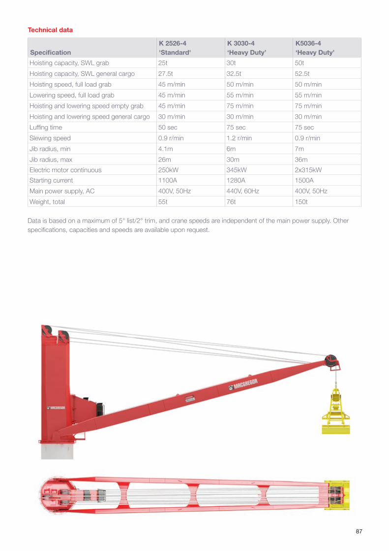
87
SpecificationK 2526-4 'Standard'
K 3030-4 ‘Heavy Duty’
K5036-4 ‘Heavy Duty’
Hoisting capacity, SWL grab 25t 30t 50t
Hoisting capacity, SWL general cargo 27.5t 32.5t 52.5t
Hoisting speed, full load grab 45 m/min 50 m/min 50 m/min
Lowering speed, full load grab 45 m/min 55 m/min 55 m/min
Hoisting and lowering speed empty grab 45 m/min 75 m/min 75 m/min
Hoisting and lowering speed general cargo 30 m/min 30 m/min 30 m/min
Luffing time 50 sec 75 sec 75 sec
Slewing speed 0.9 r/min 1.2 r/min 0.9 r/min
Jib radius, min 4.1m 6m 7m
Jib radius, max 26m 30m 36m
Electric motor continuous 250kW 345kW 2x315kW
Starting current 1100A 1280A 1500A
Main power supply, AC 400V, 50Hz 440V, 60Hz 400V, 50Hz
Weight, total 55t 76t 150t
Data is based on a maximum of 5° list/2° trim, and crane speeds are independent of the main power supply. Other specifications, capacities and speeds are available upon request.
Technical data
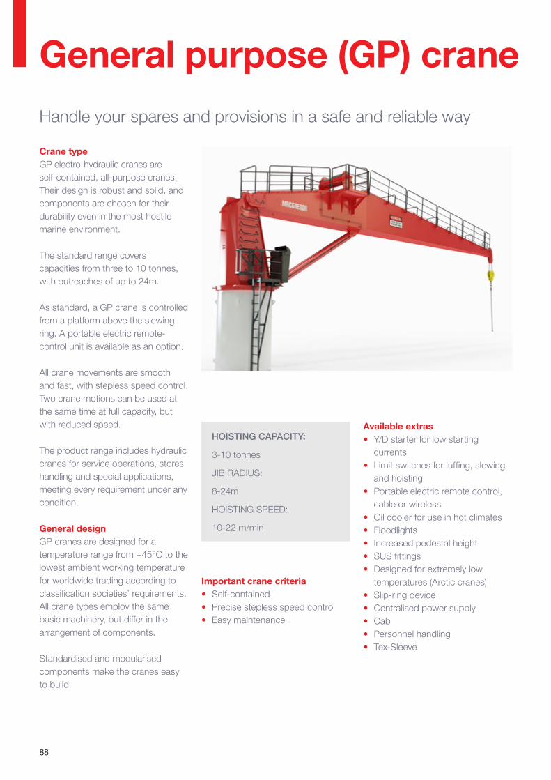
88
HOISTING CAPACITY:
3-10 tonnes
JIB RADIUS:
8-24m
HOISTING SPEED:
10-22 m/min
Crane type GP electro-hydraulic cranes are self-contained, all-purpose cranes. Their design is robust and solid, and components are chosen for their durability even in the most hostile marine environment.
The standard range covers capacities from three to 10 tonnes, with outreaches of up to 24m.
As standard, a GP crane is controlled from a platform above the slewing ring. A portable electric remote-control unit is available as an option.
All crane movements are smooth and fast, with stepless speed control. Two crane motions can be used at the same time at full capacity, but with reduced speed.
The product range includes hydraulic cranes for service operations, stores handling and special applications, meeting every requirement under any condition.
General design GP cranes are designed for a temperature range from +45°C to the lowest ambient working temperature for worldwide trading according to classification societies’ requirements. All crane types employ the same basic machinery, but differ in the arrangement of components.
Standardised and modularised components make the cranes easy to build.
Available extras• Y/D starter for low starting
currents• Limit switches for luffing, slewing
and hoisting• Portable electric remote control,
cable or wireless• Oil cooler for use in hot climates• Floodlights• Increased pedestal height• SUS fittings• Designed for extremely low
temperatures (Arctic cranes)• Slip-ring device• Centralised power supply • Cab• Personnel handling• Tex-Sleeve
Important crane criteria• Self-contained• Precise stepless speed control• Easy maintenance
General purpose (GP) craneHandle your spares and provisions in a safe and reliable way
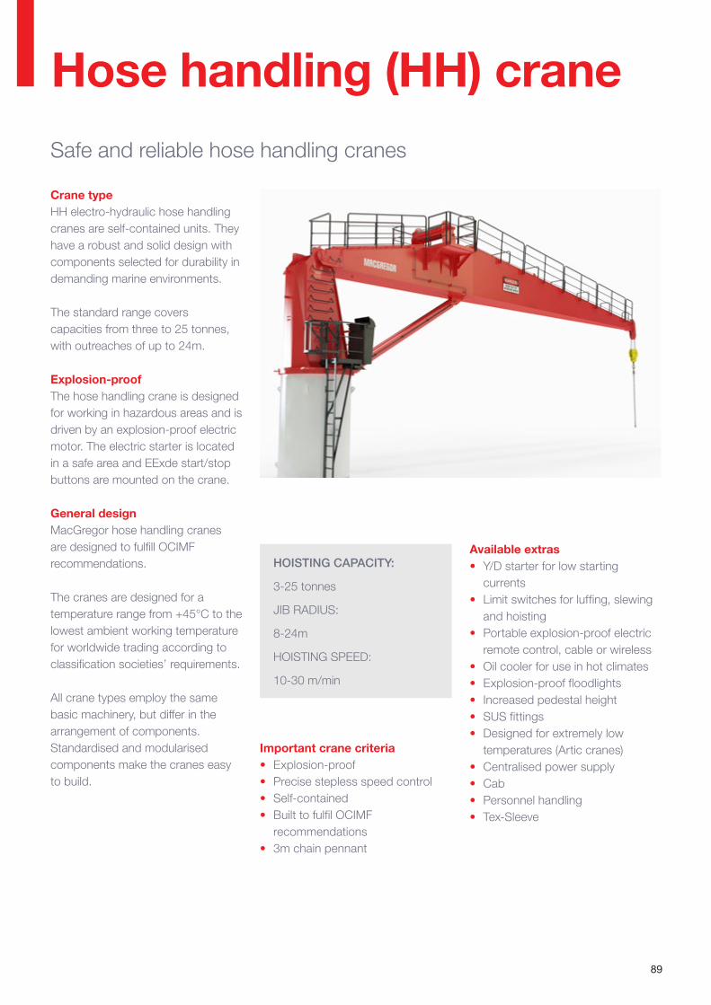
89
Hose handling (HH) craneSafe and reliable hose handling cranes
HOISTING CAPACITY:
3-25 tonnes
JIB RADIUS:
8-24m
HOISTING SPEED:
10-30 m/min
Available extras • Y/D starter for low starting
currents• Limit switches for luffing, slewing
and hoisting• Portable explosion-proof electric
remote control, cable or wireless• Oil cooler for use in hot climates• Explosion-proof floodlights• Increased pedestal height• SUS fittings• Designed for extremely low
temperatures (Artic cranes)• Centralised power supply• Cab• Personnel handling• Tex-Sleeve
Crane type HH electro-hydraulic hose handling cranes are self-contained units. They have a robust and solid design with components selected for durability in demanding marine environments.
The standard range covers capacities from three to 25 tonnes, with outreaches of up to 24m.
Explosion-proofThe hose handling crane is designed for working in hazardous areas and is driven by an explosion-proof electric motor. The electric starter is located in a safe area and EExde start/stop buttons are mounted on the crane.
General design MacGregor hose handling cranes are designed to fulfill OCIMF recommendations.
The cranes are designed for a temperature range from +45°C to the lowest ambient working temperature for worldwide trading according to classification societies’ requirements.
All crane types employ the same basic machinery, but differ in the arrangement of components. Standardised and modularised components make the cranes easy to build.
Important crane criteria • Explosion-proof• Precise stepless speed control• Self-contained• Built to fulfil OCIMF
recommendations• 3m chain pennant
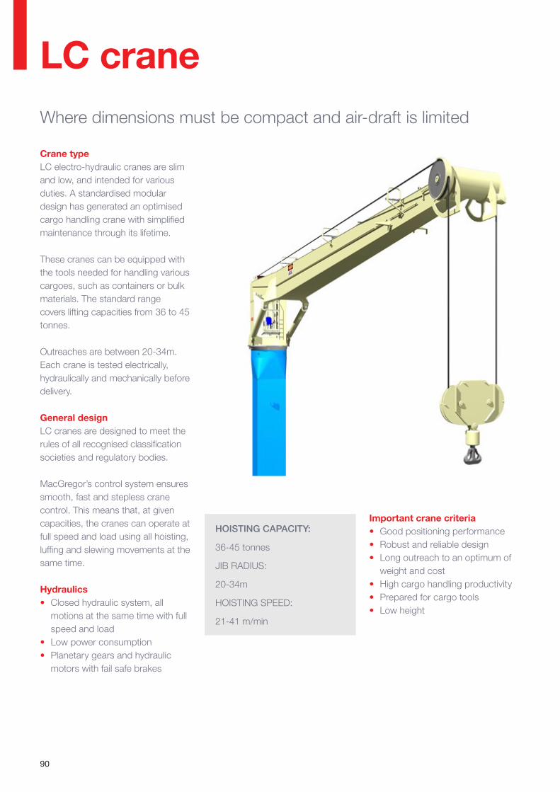
90
LC crane
Important crane criteria• Good positioning performance• Robust and reliable design• Long outreach to an optimum of
weight and cost• High cargo handling productivity• Prepared for cargo tools• Low height
Crane typeLC electro-hydraulic cranes are slim and low, and intended for various duties. A standardised modular design has generated an optimised cargo handling crane with simplified maintenance through its lifetime.
These cranes can be equipped with the tools needed for handling various cargoes, such as containers or bulk materials. The standard range covers lifting capacities from 36 to 45 tonnes.
Outreaches are between 20-34m. Each crane is tested electrically, hydraulically and mechanically before delivery.
General designLC cranes are designed to meet the rules of all recognised classification societies and regulatory bodies.
MacGregor’s control system ensures smooth, fast and stepless crane control. This means that, at given capacities, the cranes can operate at full speed and load using all hoisting, luffing and slewing movements at the same time.
Hydraulics• Closed hydraulic system, all
motions at the same time with full speed and load
• Low power consumption• Planetary gears and hydraulic
motors with fail safe brakes
Where dimensions must be compact and air-draft is limited
HOISTING CAPACITY:
36-45 tonnes
JIB RADIUS:
20-34m
HOISTING SPEED:
21-41 m/min
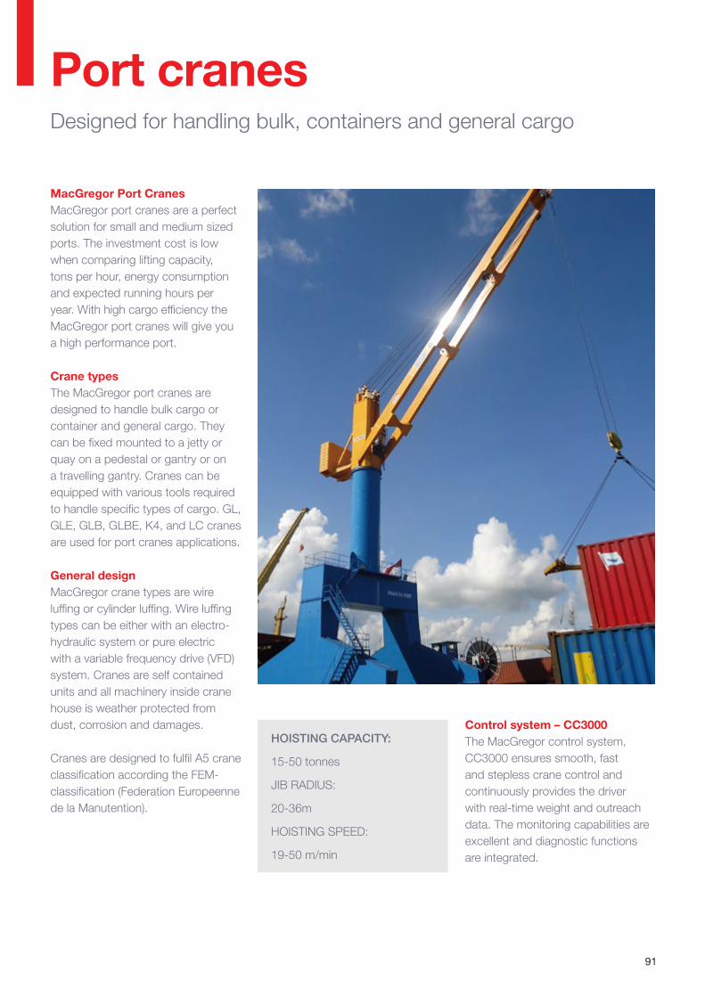
91
Port cranesDesigned for handling bulk, containers and general cargo
MacGregor Port CranesMacGregor port cranes are a perfect solution for small and medium sized ports. The investment cost is low when comparing lifting capacity, tons per hour, energy consumption and expected running hours per year. With high cargo efficiency the MacGregor port cranes will give you a high performance port.
Crane typesThe MacGregor port cranes are designed to handle bulk cargo or container and general cargo. They can be fixed mounted to a jetty or quay on a pedestal or gantry or on a travelling gantry. Cranes can be equipped with various tools required to handle specific types of cargo. GL, GLE, GLB, GLBE, K4, and LC cranes are used for port cranes applications.
General designMacGregor crane types are wire luffing or cylinder luffing. Wire luffing types can be either with an electro-hydraulic system or pure electric with a variable frequency drive (VFD) system. Cranes are self contained units and all machinery inside crane house is weather protected from dust, corrosion and damages.
Cranes are designed to fulfil A5 crane classification according the FEM-classi fication (Federation Europeenne de la Manutention).
Control system – CC3000The MacGregor control system, CC3000 ensures smooth, fast and stepless crane control and continuously provides the driver with real-time weight and outreach data. The monitoring capabilities are excellent and diagnostic functions are integrated.
HOISTING CAPACITY:
15-50 tonnes
JIB RADIUS:
20-36m
HOISTING SPEED:
19-50 m/min
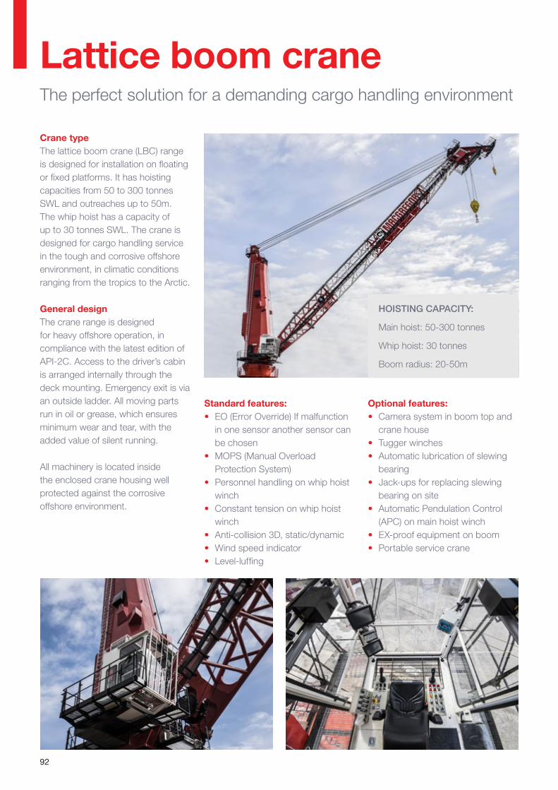
92
HOISTING CAPACITY:
Main hoist: 50-300 tonnes
Whip hoist: 30 tonnes
Boom radius: 20-50m
Crane typeThe lattice boom crane (LBC) range is designed for installation on floating or fixed platforms. It has hoisting capacities from 50 to 300 tonnes SWL and outreaches up to 50m. The whip hoist has a capacity of up to 30 tonnes SWL. The crane is designed for cargo handling service in the tough and corrosive offshore environment, in climatic conditions ranging from the tropics to the Arctic.
General designThe crane range is designed for heavy offshore operation, in compliance with the latest edition of API-2C. Access to the driver’s cabin is arranged internally through the deck mounting. Emergency exit is via an outside ladder. All moving parts run in oil or grease, which ensures minimum wear and tear, with the added value of silent running.
All machinery is located inside the enclosed crane housing well protected against the corrosive offshore environment.
Standard features:• EO (Error Override) If malfunction
in one sensor another sensor can be chosen
• MOPS (Manual Overload Protection System)
• Personnel handling on whip hoist winch
• Constant tension on whip hoist winch
• Anti-collision 3D, static/dynamic• Wind speed indicator• Level-luffing
Lattice boom craneThe perfect solution for a demanding cargo handling environment
Optional features:• Camera system in boom top and
crane house• Tugger winches• Automatic lubrication of slewing
bearing• Jack-ups for replacing slewing
bearing on site • Automatic Pendulation Control
(APC) on main hoist winch• EX-proof equipment on boom• Portable service crane
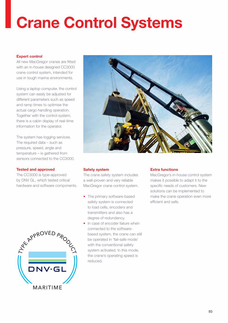
93
Crane Control Systems
Safety systemThe crane safety system includes a well-proven and very reliable MacGregor crane control system.
• The primary software-based safety system is connected to load cells, encoders and transmitters and also has a degree of redundancy.
• In case of encoder failure when connected to the software-based system, the crane can still be operated in ’fail-safe mode’ with the conventional safety system activated. In this mode, the crane’s operating speed is reduced.
Expert controlAll new MacGregor cranes are fitted with an in-house designed CC3000 crane control system, intended for use in tough marine environments.
Using a laptop computer, the control system can easily be adjusted for different parameters such as speed and ramp times to optimise the actual cargo handling operation. Together with the control system, there is a cabin display of real-time information for the operator.
The system has logging services. The required data – such as pressure, speed, angle and temperature – is gathered from sensors connected to the CC3000.
Tested and approvedThe CC3000 is type-approved by DNV GL, which tested critical hardware and software components.
Extra functionsMacGregor’s in-house control system makes it possible to adapt it to the specific needs of customers. New solutions can be implemented to make the crane operation even more efficient and safe.

94
MacGregor crane information system
Human Machine Interface (HMI)
Cabin displayThe cabin display is located inside the cabin and is equipped with the MacGregor software system, MacHeavyvisor. The main purpose of the display is to show the operator real time information including weight and outreach data. It also logs information about the operation of the crane which can be used for future analysis.
The cabin display can be connected to the ship’s office computer located on the bridge, which has similar functions to the cabin display.
Real-time information on active systems
Load/speed/outreach information
Errors/warnings/events
Logs information for analysis
Touchscreen display
The crane information system continuously provides the driver with real-time weight and outreach data
Display features and functions:• Load and outreach • Hoisting speed• Motion indicator for speed reduce
and stop• Speed limited areas• Stop limits• Audible alarms• View and analyse error messages• General messages for the operator • Trouble-shooting manuals• Crane components operation
status• Lift height (optional)• List and trim (optional)
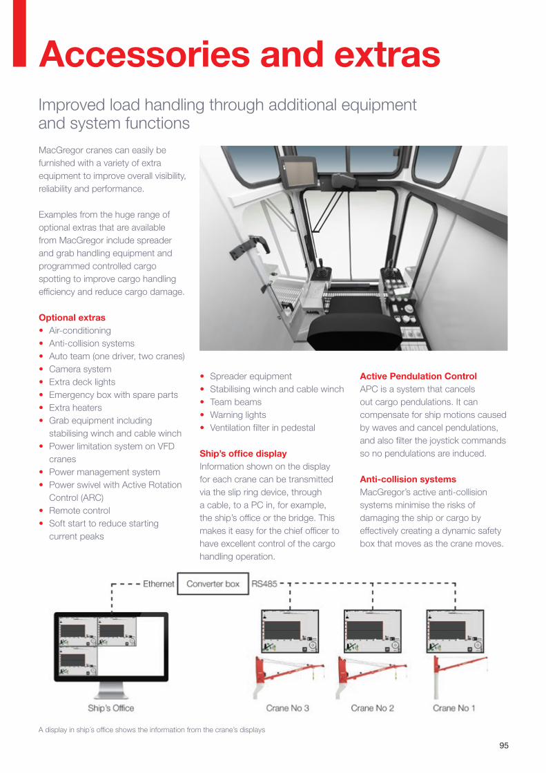
95
A display in ship´s office shows the information from the crane’s displays
MacGregor cranes can easily be furnished with a variety of extra equipment to improve overall visibility, reliability and performance.
Examples from the huge range of optional extras that are available from MacGregor include spreader and grab handling equipment and programmed controlled cargo spotting to improve cargo handling efficiency and reduce cargo damage.
Optional extras• Air-conditioning • Anti-collision systems• Auto team (one driver, two cranes)• Camera system • Extra deck lights• Emergency box with spare parts• Extra heaters• Grab equipment including
stabilising winch and cable winch• Power limitation system on VFD
cranes• Power management system• Power swivel with Active Rotation
Control (ARC)• Remote control• Soft start to reduce starting
current peaks
Accessories and extrasImproved load handling through additional equipment and system functions
• Spreader equipment• Stabilising winch and cable winch• Team beams• Warning lights• Ventilation filter in pedestal
Ship’s office displayInformation shown on the display for each crane can be transmitted via the slip ring device, through a cable, to a PC in, for example, the ship’s office or the bridge. This makes it easy for the chief officer to have excellent control of the cargo handling operation.
Active Pendulation ControlAPC is a system that cancels out cargo pendulations. It can compensate for ship motions caused by waves and cancel pendulations, and also filter the joystick commands so no pendulations are induced.
Anti-collision systemsMacGregor’s active anti-collision systems minimise the risks of damaging the ship or cargo by effectively creating a dynamic safety box that moves as the crane moves.
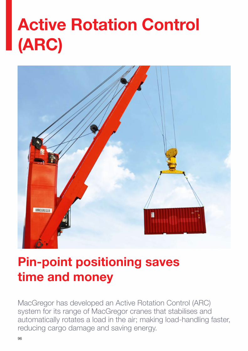
96
MacGregor has developed an Active Rotation Control (ARC) system for its range of MacGregor cranes that stabilises and automatically rotates a load in the air; making load-handling faster, reducing cargo damage and saving energy.
Pin-point positioning saves time and money
Active Rotation Control (ARC)
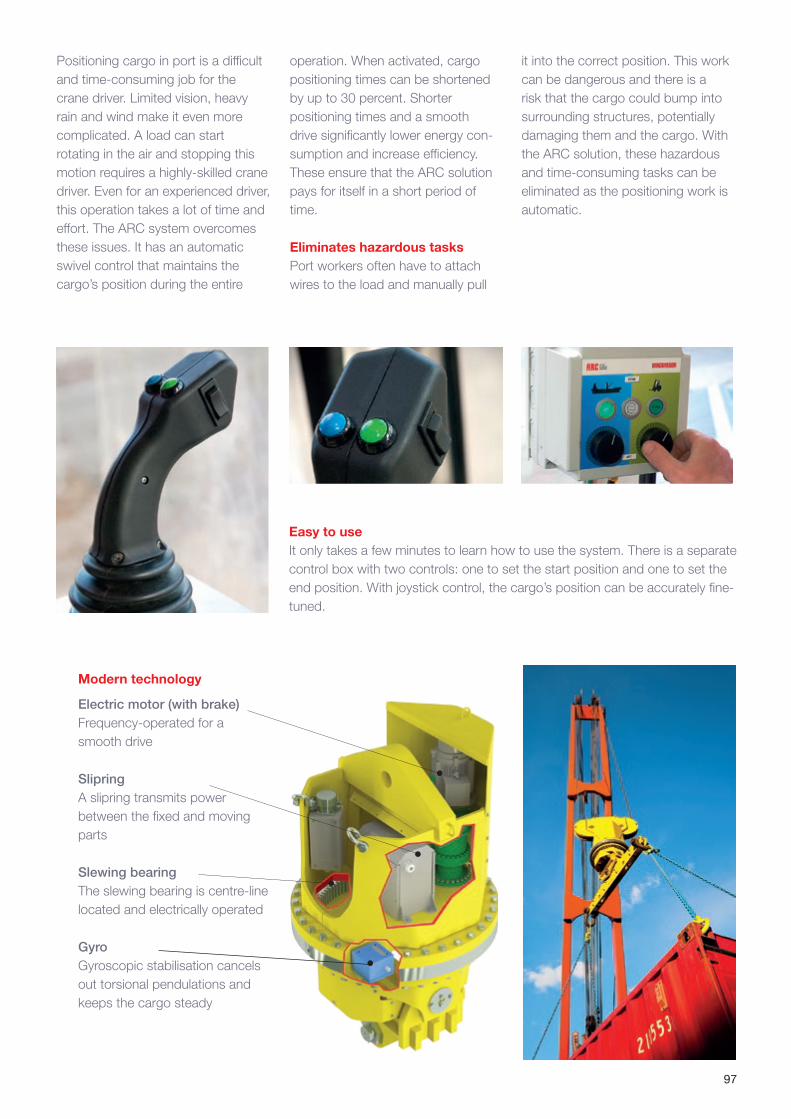
97
Positioning cargo in port is a difficult and time-consuming job for the crane driver. Limited vision, heavy rain and wind make it even more complicated. A load can start rotating in the air and stopping this motion requires a highly-skilled crane driver. Even for an experienced driver, this operation takes a lot of time and effort. The ARC system overcomes these issues. It has an automatic swivel control that maintains the cargo’s position during the entire
operation. When activated, cargo positioning times can be shortened by up to 30 percent. Shorter positioning times and a smooth drive significantly lower energy con-sumption and increase efficiency. These ensure that the ARC solution pays for itself in a short period of time.
Eliminates hazardous tasksPort workers often have to attach wires to the load and manually pull
Easy to useIt only takes a few minutes to learn how to use the system. There is a separate control box with two controls: one to set the start position and one to set the end position. With joystick control, the cargo’s position can be accurately fine-tuned.
Modern technology
Electric motor (with brake) Frequency-operated for a smooth drive
Slipring A slipring transmits power between the fixed and moving parts
Slewing bearing The slewing bearing is centre-line located and electrically operated
Gyro Gyroscopic stabilisation cancels out torsional pendulations and keeps the cargo steady
it into the correct position. This work can be dangerous and there is a risk that the cargo could bump into surrounding structures, potentially damaging them and the cargo. With the ARC solution, these hazardous and time-consuming tasks can be eliminated as the positioning work is automatic.
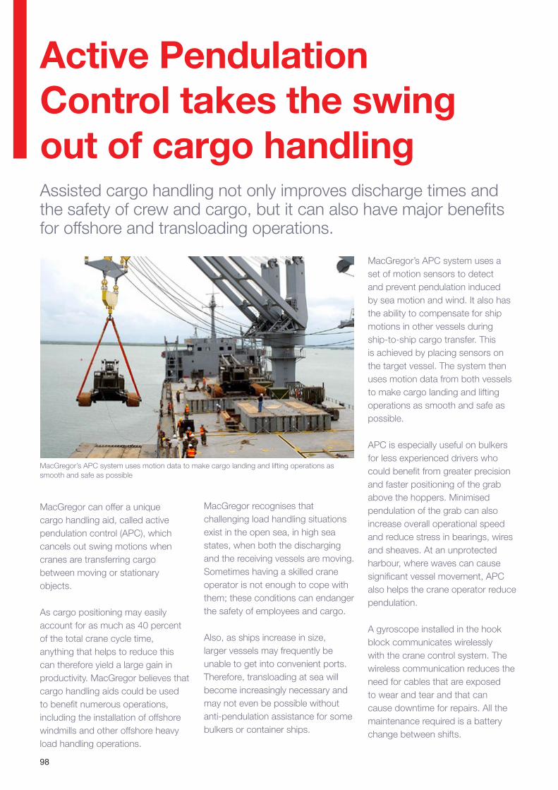
98
Active Pendulation Control takes the swing out of cargo handling
MacGregor can offer a unique cargo handling aid, called active pendulation control (APC), which cancels out swing motions when cranes are transferring cargo between moving or stationary objects.
As cargo positioning may easily account for as much as 40 percent of the total crane cycle time, anything that helps to reduce this can therefore yield a large gain in productivity. MacGregor believes that cargo handling aids could be used to benefit numerous operations, including the installation of offshore windmills and other offshore heavy load handling operations.
Assisted cargo handling not only improves discharge times and the safety of crew and cargo, but it can also have major benefits for offshore and transloading operations.
MacGregor recognises that challenging load handling situations exist in the open sea, in high sea states, when both the discharging and the receiving vessels are moving. Sometimes having a skilled crane operator is not enough to cope with them; these conditions can endanger the safety of employees and cargo.
Also, as ships increase in size, larger vessels may frequently be unable to get into convenient ports. Therefore, transloading at sea will become increasingly necessary and may not even be possible without anti-pendulation assistance for some bulkers or container ships.
MacGregor’s APC system uses a set of motion sensors to detect and prevent pendulation induced by sea motion and wind. It also has the ability to compensate for ship motions in other vessels during ship-to-ship cargo transfer. This is achieved by placing sensors on the target vessel. The system then uses motion data from both vessels to make cargo landing and lifting operations as smooth and safe as possible.
APC is especially useful on bulkers for less experienced drivers who could benefit from greater precision and faster positioning of the grab above the hoppers. Minimised pendulation of the grab can also increase overall operational speed and reduce stress in bearings, wires and sheaves. At an unprotected harbour, where waves can cause significant vessel movement, APC also helps the crane operator reduce pendulation.
A gyroscope installed in the hook block communicates wirelessly with the crane control system. The wireless communication reduces the need for cables that are exposed to wear and tear and that can cause downtime for repairs. All the maintenance required is a battery change between shifts.
MacGregor’s APC system uses motion data to make cargo landing and lifting operations as smooth and safe as possible
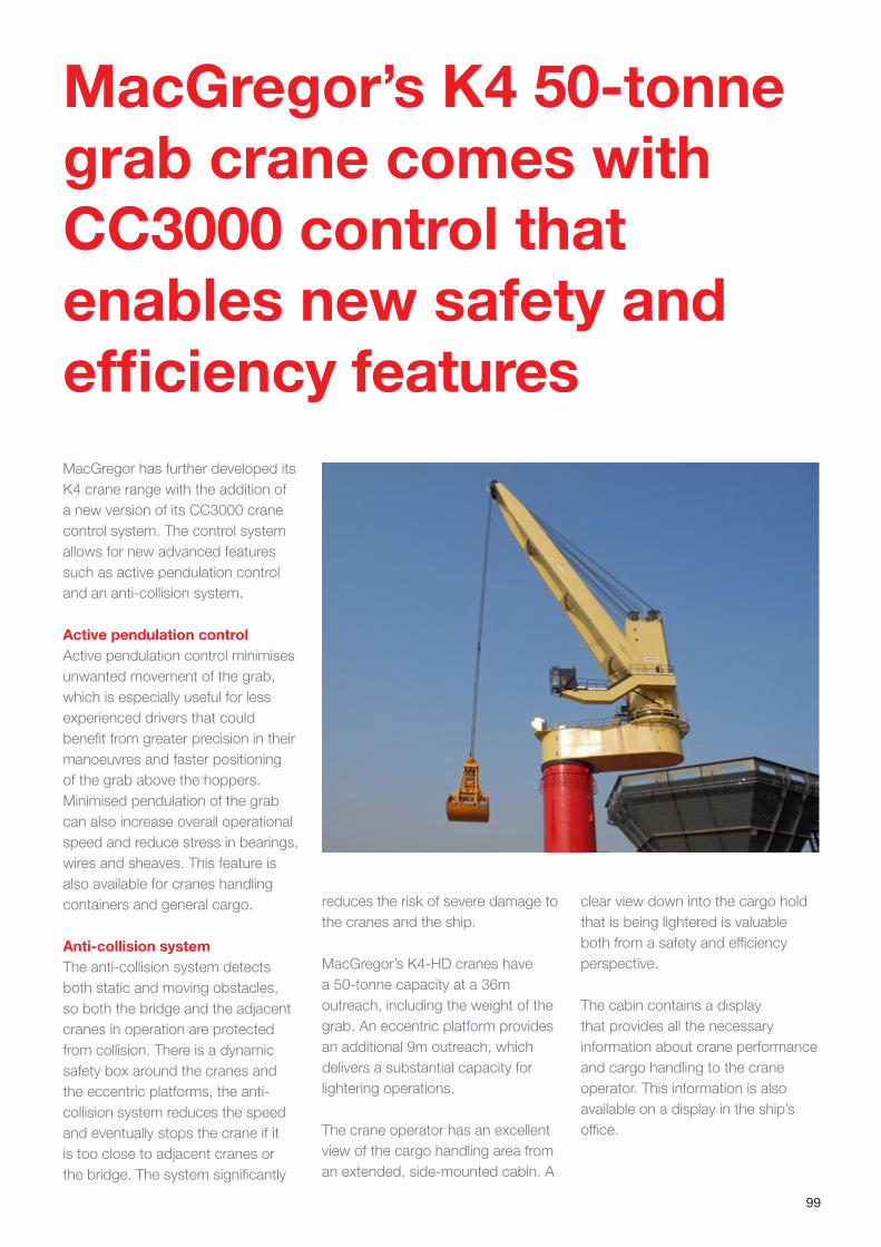
99
MacGregor’s K4 50-tonne grab crane comes with CC3000 control that enables new safety and efficiency featuresMacGregor has further developed its K4 crane range with the addition of a new version of its CC3000 crane control system. The control system allows for new advanced features such as active pendulation control and an anti-collision system.
Active pendulation controlActive pendulation control minimises unwanted movement of the grab, which is especially useful for less experienced drivers that could benefit from greater precision in their manoeuvres and faster positioning of the grab above the hoppers. Minimised pendulation of the grab can also increase overall operational speed and reduce stress in bearings, wires and sheaves. This feature is also available for cranes handling containers and general cargo.
Anti-collision systemThe anti-collision system detects both static and moving obstacles, so both the bridge and the adjacent cranes in operation are protected from collision. There is a dynamic safety box around the cranes and the eccentric platforms, the anti-collision system reduces the speed and eventually stops the crane if it is too close to adjacent cranes or the bridge. The system significantly
reduces the risk of severe damage to the cranes and the ship.
MacGregor’s K4-HD cranes have a 50-tonne capacity at a 36m outreach, including the weight of the grab. An eccentric platform provides an additional 9m outreach, which delivers a substantial capacity for lightering operations.
The crane operator has an excellent view of the cargo handling area from an extended, side-mounted cabin. A
clear view down into the cargo hold that is being lightered is valuable both from a safety and efficiency perspective.
The cabin contains a display that provides all the necessary information about crane performance and cargo handling to the crane operator. This information is also available on a display in the ship’s office.
100
Two new control system features deliver enhanced cargo handling capabilities for MacGregor cranes; one allows a single operator to control two separate cranes in a team lift, the other refines the anti-collision separation between adjacent cranes
MacGregor continuously hones its products, never satisfied that they cannot be improved. Two important advances to its market-leading CC3000 control system for its range of deck cranes are presented. The ‘Auto Team’ and ‘anti-collision’ functions both expand operational capabilities and can be implemented on new MacGregor cranes equipped with the latest version of CC3000. It is also possible to update older cranes equipped with this control system to incorporate these functions.
“The better our crane control systems are, the greater the productivity of the crane,” says Per-Erik Nilsson, Marketing and Sales Director for MacGregor Cranes. “If we can deliver faster, safer and more accurate cargo handling capabilities, our customers will benefit from improved port turnaround times. In some cases, they can perform more complex lifts than previously possible. For example, big and bulky project cargo will be loaded and discharged much faster having these features installed.
“It has always been possible to operate twin cranes – two cranes on the some foundation – in team with one operator. But to operate two separate cranes with only one operator is a real breakthrough and significantly extends a crane’s, and therefore a vessel’s, capabilities.”
Automatic control of separate cranes is made possible by the CC3000’s ‘Auto Team’ function for team lifts. “With the CC3000 control system running in Auto Team mode, lifts are faster and safer than with two separate operators using manual controls. Auto Team also makes it possible for two sets of twin-cranes to be operated, which means that one operator can control four cranes,” he notes. “Special ‘team beams’ that are sometimes used during manual team lifts are not needed in Auto Team mode.”
Before a Team lift can start the cranes need to be positioned correctly. The lift lines are attached to the cargo; the lift wires of both cranes are tensioned and the
New crane control features enable faster, safer and closer lifts
load is lifted and balanced. The position of the cranes is then calibrated. Auto Team mode can now be engaged and the lift commenced; the distance between the crane hooks and the rotation of the cargo is maintained during the Team lift operation.
Lift data is displayed on a screen in the operator’s cabin; it is also possible to use an external display for supervising the operation from the ship’s bridge. The display provides information about weight, outreach, lift height and lift speed for both cranes. Auto Team has a safety system for avoiding and dealing with overload situations. It provides on-screen information on how to prevent and balance-out Team overload conditions.
MacGregor’s second CC3000 advance is its anti-collision feature, which is used to prevent collisions between adjacent cranes. Based on an earlier anticollision system for dynamic obstacles, anti-collision allows cranes to work closer together, while maintaining a safe separation. The previous system used a ‘stop wall’ between the cranes, while anti-collision employs a ‘safety box’ around the crane and its jib,” he says. “anti-collision makes sure that the boxes of adjacent cranes do not overlap with each other.
“Anti-collision is very similar to the normal anti-collision system in terms of encoders and alarms, but instead of having a defined stop-zone, it calculates a safety box around each crane jib and crane housing. This expands the cranes’ operating parameters, and ultimately improves cargo handling rates. In addition to the calculated no-go areas, there are also precautionary approach zones where luffing and/or slewing speed is automatically reduced. Anti-collision can also be used to avoid static obstacles,” he adds.
Source: MacGregor News spring 2013.
Case study:
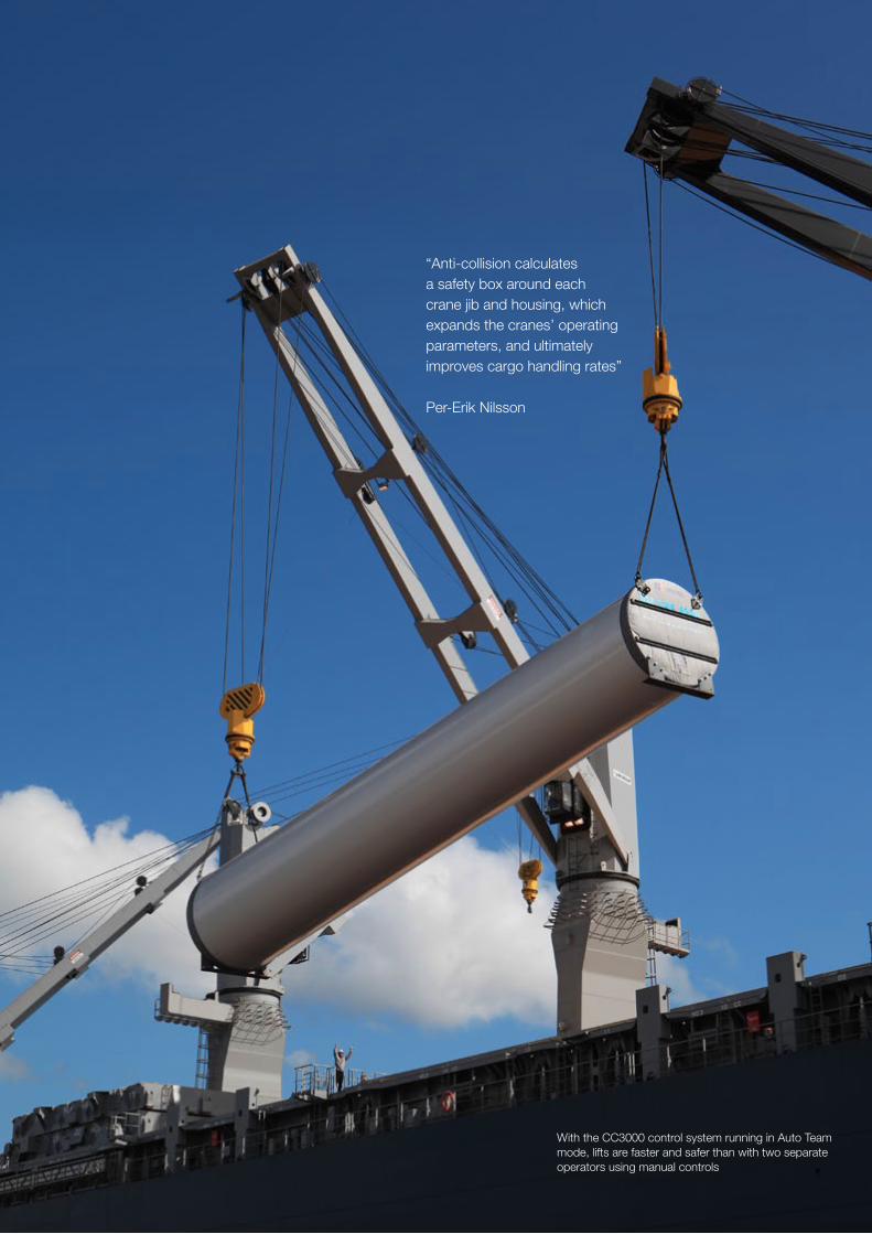
101
“Anti-collision calculates a safety box around each crane jib and housing, which expands the cranes’ operating parameters, and ultimately improves cargo handling rates”
Per-Erik Nilsson
With the CC3000 control system running in Auto Team mode, lifts are faster and safer than with two separate operators using manual controls
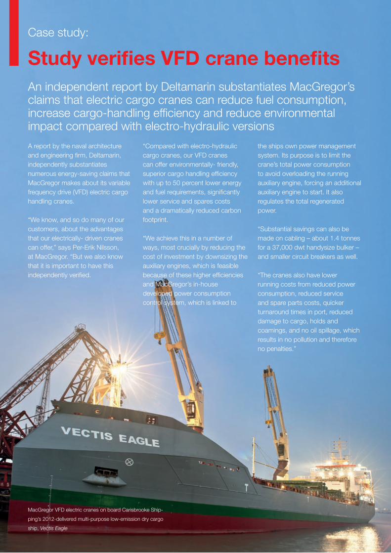
102
Study verifies VFD crane benefitsAn independent report by Deltamarin substantiates MacGregor’s claims that electric cargo cranes can reduce fuel consumption, increase cargo-handling efficiency and reduce environmental impact compared with electro-hydraulic versions
A report by the naval architecture and engineering firm, Deltamarin, independently substantiates numerous energy-saving claims that MacGregor makes about its variable frequency drive (VFD) electric cargo handling cranes.
“We know, and so do many of our customers, about the advantages that our electrically- driven cranes can offer,” says Per-Erik Nilsson, at MacGregor. “But we also know that it is important to have this independently verified.
“Compared with electro-hydraulic cargo cranes, our VFD cranes can offer environmentally- friendly, superior cargo handling efficiency with up to 50 percent lower energy and fuel requirements, significantly lower service and spares costs and a dramatically reduced carbon footprint.
“We achieve this in a number of ways, most crucially by reducing the cost of investment by downsizing the auxiliary engines, which is feasible because of these higher efficiencies and MacGregor’s in-house developed power consumption control system, which is linked to
the ships own power management system. Its purpose is to limit the crane’s total power consumption to avoid overloading the running auxiliary engine, forcing an additional auxiliary engine to start. It also regulates the total regenerated power.
“Substantial savings can also be made on cabling – about 1.4 tonnes for a 37,000 dwt handysize bulker – and smaller circuit breakers as well.
“The cranes also have lower running costs from reduced power consumption, reduced service and spare parts costs, quicker turnaround times in port, reduced damage to cargo, holds and coamings, and no oil spillage, which results in no pollution and therefore no penalties.”
MacGregor VFD electric cranes on board Carisbrooke Ship-
ping’s 2012-delivered multi-purpose low-emission dry cargo
ship, Vectis Eagle
Case study:
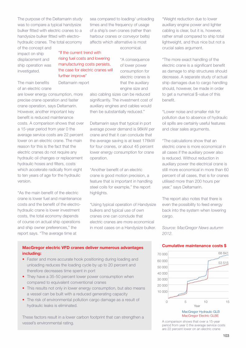
103
The purpose of the Deltamarin study was to compare a typical handysize bulker fitted with electric cranes to a handysize bulker fitted with electro-hydraulic cranes. The total economy of the concept and impact on ship displacement and ship operation was investigated.
The main benefits of an electric crane are lower energy consumption, more precise crane operation and faster crane operation, says Deltamarin. However, another important key benefit is reduced maintenance costs. A comparison shows that over a 15-year period from year 0 the average service costs are 22 percent lower on an electric crane. The main reason for this is the fact that the electric cranes do not require any hydraulic oil changes or replacement hydraulic hoses and filters, costs which accelerate radically from eight to ten years of age for the hydraulic version.
“As the main benefit of the electric crane is lower fuel and maintenance costs and the benefit of the electro-hydraulic crane is lower investment costs, the total economy depends of course on actual ship operations and ship owner preferences,” the report says. “The average time at
sea compared to loading/ unloading times and the frequency of usage of a ship’s own cranes (rather than harbour cranes or conveyor belts) affects which alternative is most
economical.
“A consequence of lower power consumption for electric cranes is that the auxiliary engine size and
also cabling sizes can be reduced significantly. The investment cost of auxiliary engines and cables would then be substantially reduced.”
Deltamarin says that typical in port average power demand is 98kW per crane and that it can conclude that the average saving is at least 176kW for four cranes, or about 45 percent lower energy consumption for crane operation.
“Another benefit of an electric crane is good motion precision, a feature that is important in handling steel coils for example,” the report highlights.
“Using typical operation of Handysize bulkers and typical use of own cranes one can conclude that electric cranes are more economical in most cases on a Handysize bulker.
MacGregor electric VFD cranes deliver numerous advantages including: • Faster and more accurate hook positioning during loading and
unloading reduces the loading cycle by up to 20 percent and therefore decreases time spent in port
• They have a 35-50 percent lower power consumption when compared to equivalent conventional cranes
• This results not only in lower energy consumption, but also means a vessel can be built with a reduced generating capacity
• The risk of environmental pollution cargo damage as a result of hydraulic leaks is eliminated.
These factors result in a lower carbon footprint that can strengthen a vessel’s environmental rating.
“Weight reduction due to lower auxiliary engine power and lighter cabling is clear, but it is, however, rather small compared to ship total lightweight, and thus nice but not a crucial sales argument.
“The more exact handling of the electric crane is a significant benefit as damage to ship structures should decrease. A separate study of actual ship damages due to cargo handling should, however, be made in order to get a numerical $-value of this benefit.
“Lower noise and smaller risk for pollution due to absence of hydraulic oil spills are certainly useful features and clear sales arguments.
“The calculations show that an electric crane is more economical in all cases if the auxiliary power also is reduced. Without reduction in auxiliary power the electrical crane is still more economical in more than 60 percent of all cases, that is for cranes utilised more than 200 hours per year,” says Deltamarin.
The report also notes that there is even the possibility to feed energy back into the system when lowering cargo.
Source: MacGregor News autumn 2012.
“If the current trend with rising fuel costs and lowering manufacturing costs persists, the case for electric cranes will further improve”
Deltamarin report
0 5 10 15Year
MacGregor Hydraulic GLBMacGregor Electric GLBE
70 000 68 841
53 51560 000
50 000
40 000
30 000
20 000
10 000
Cumulative maintenance costs $
A comparison shows that over a 15-year period from year 0 the average service costs are 22 percent lower on an electric crane
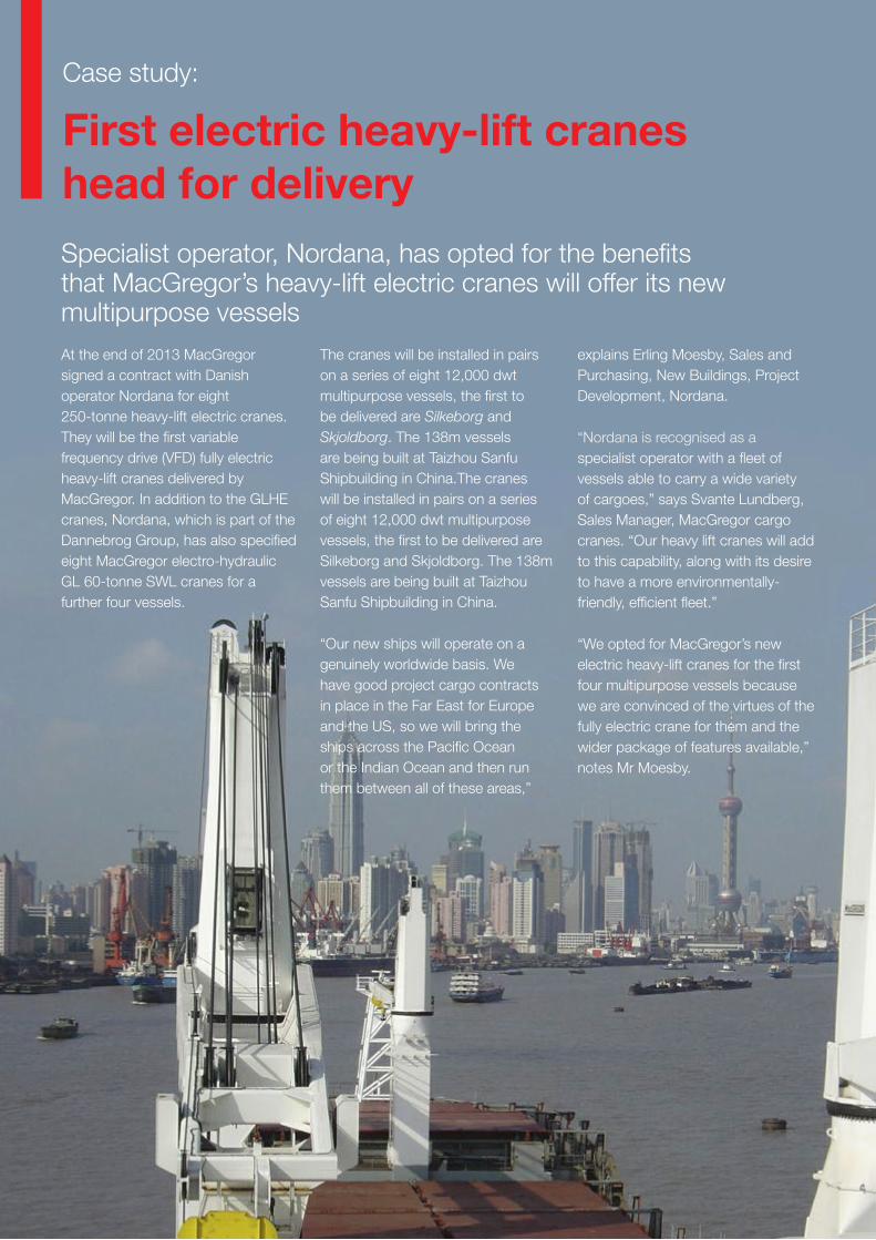
104
First electric heavy-lift cranes head for deliverySpecialist operator, Nordana, has opted for the benefits that MacGregor’s heavy-lift electric cranes will offer its new multipurpose vesselsAt the end of 2013 MacGregor signed a contract with Danish operator Nordana for eight 250-tonne heavy-lift electric cranes. They will be the first variable frequency drive (VFD) fully electric heavy-lift cranes delivered by MacGregor. In addition to the GLHE cranes, Nordana, which is part of the Dannebrog Group, has also specified eight MacGregor electro-hydraulic GL 60-tonne SWL cranes for a further four vessels.
The cranes will be installed in pairs on a series of eight 12,000 dwt multipurpose vessels, the first to be delivered are Silkeborg and Skjoldborg. The 138m vessels are being built at Taizhou Sanfu Shipbuilding in China.The cranes will be installed in pairs on a series of eight 12,000 dwt multipurpose vessels, the first to be delivered are Silkeborg and Skjoldborg. The 138m vessels are being built at Taizhou Sanfu Shipbuilding in China.
“Our new ships will operate on a genuinely worldwide basis. We have good project cargo contracts in place in the Far East for Europe and the US, so we will bring the ships across the Pacific Ocean or the Indian Ocean and then run them between all of these areas,”
explains Erling Moesby, Sales and Purchasing, New Buildings, Project Development, Nordana.
“Nordana is recognised as a specialist operator with a fleet of vessels able to carry a wide variety of cargoes,” says Svante Lundberg, Sales Manager, MacGregor cargo cranes. “Our heavy lift cranes will add to this capability, along with its desire to have a more environmentally-friendly, efficient fleet.”
“We opted for MacGregor’s new electric heavy-lift cranes for the first four multipurpose vessels because we are convinced of the virtues of the fully electric crane for them and the wider package of features available,” notes Mr Moesby.
Case study:

105
“Efficiency and environmental issues are extremely important aspects of our decision making and our daily operations. This applies to every piece of equipment that we bring on board. Any efficiency savings are not just good for the environment; they also save us fuel, which saves us money. This is important in today’s market. It also means that the secondhand tonnage value is higher.
“A good service network is also extremely important to us. We operate worldwide so we need to deal with partners that also operate on a worldwide service.”
Improved port turnaround times In addition to the cranes, MacGregor will deliver a package of extra features that will enhance the safety and load-handling efficiency of the cranes. This package includes ‘Auto Team’, the anti-collision software, ‘Anti-collision’, the cargo handling aid, ARC, and a power limitation system.
‘Auto Team’ and ‘Anti-collision’ functions are relatively new advances to MacGregor’s market-leading CC3000 control system, which is fitted to its range of deck cranes; one allows a single operator to control two separate cranes in a team lift, the other refines the anti-collision separation between adjacent cranes by employing a ‘safety box’
“There are three or four main suppliers for electro-hydraulic cranes as we see it, but we are convinced that MacGregor offers the best possibilities for the electric crane. For our other vessels we opted for smaller more traditional electro-hydraulic versions with MacGregor’s cargo handling device, Active Rotation Control, and again we are convinced that they offer the best package for these ships.”
More efficient lifts “We are expecting good things from the cranes,” continues Mr Moesby, “We are convinced that the total package they offer will work well for us. We know they are making a good impression on the market, as we took references from other operators using electric cranes.
Mr Lundberg says that Nordana will benefit from the operational and environmental advantages of VFD cranes. “Most importantly, they deliver enhanced efficiency, mainly attributable to faster and more accurate load positioning which reduces the time spent in port, along with a 30 to 35 percent reduction in power consumption compared to electro-hydraulic cranes. They also eliminate the need for hydraulic oil.”
Mr Moesby says that multipurpose ships take a long time to load and discharge in port. “If it costs an operator $10,000 a day to use the vessel, then every hour less in port is money saved.
around the crane and its jib. ARC is designed to assist crane operators when positioning cargo. It allows 20 to 30 percent quicker cargo positioning, as well as improving safety standards.
“The better our crane control systems are, the greater the
productivity of the crane,” says Mr Lundberg. “If we can deliver faster, safer and more accurate cargo handling capabilities, our customers
will benefit from improved port turnaround times. In some cases, they can perform more complex lifts than previously possible. For example, big and bulky project cargo will be loaded and discharged much faster having these features installed.
The Nordana vessels will also feature power limitation systems with dynamic values. “The main purpose of the power limitation system is to enable better control of power distribution,” says Mr Lundberg. “Electric cranes have the added advantage that power, generated from actually using the cranes, can be fed back into the system. The power limitation system not only restricts the total power consumed, it also limits the total regenerated power from the deck cranes to the ship to avoid problems with the ship’s power system.”
Source: MacGregor News autumn 2014.
“We are convinced that MacGregor offers the best possibilities for the electric crane”
Erling Moesby
Four 12,000 dwt multipurpose vessels for Nordana will feature MacGregor’s first 250-tonne SWL electric heavy-lift crane
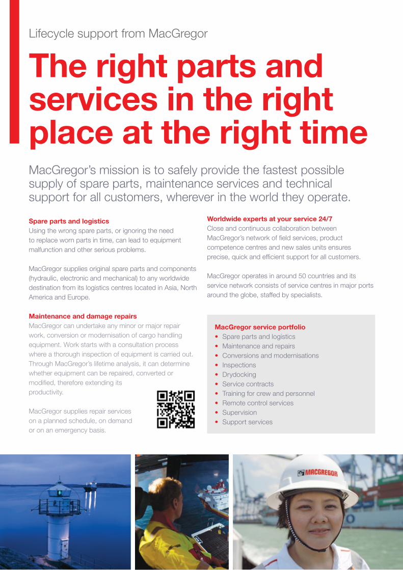
106
The right parts and services in the right place at the right timeMacGregor’s mission is to safely provide the fastest possible supply of spare parts, maintenance services and technical support for all customers, wherever in the world they operate.
MacGregor service portfolio• Spare parts and logistics• Maintenance and repairs• Conversions and modernisations• Inspections• Drydocking• Service contracts• Training for crew and personnel• Remote control services• Supervision• Support services
Spare parts and logisticsUsing the wrong spare parts, or ignoring the need to replace worn parts in time, can lead to equipment malfunction and other serious problems.
MacGregor supplies original spare parts and components (hydraulic, electronic and mechanical) to any worldwide destination from its logistics centres located in Asia, North America and Europe.
Maintenance and damage repairsMacGregor can undertake any minor or major repair work, conversion or modernisation of cargo handling equipment. Work starts with a consultation process where a thorough inspection of equipment is carried out. Through MacGregor’s lifetime analysis, it can determine whether equipment can be repaired, converted or modified, therefore extending its productivity.
MacGregor supplies repair services on a planned schedule, on demand or on an emergency basis.
Worldwide experts at your service 24/7 Close and continuous collaboration between MacGregor’s network of field services, product competence centres and new sales units ensures precise, quick and efficient support for all customers.
MacGregor operates in around 50 countries and its service network consists of service centres in major ports around the globe, staffed by specialists.
Lifecycle support from MacGregor
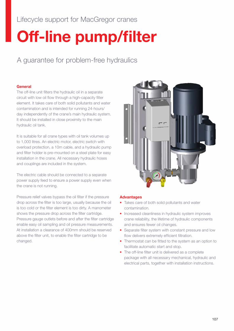
107
GeneralThe off-line unit filters the hydraulic oil in a separate circuit with low oil flow through a high-capacity filter element. It takes care of both solid pollutants and water contamination and is intended for running 24-hours/day independently of the crane’s main hydraulic system. It should be installed in close proximity to the main hydraulic oil tank.
It is suitable for all crane types with oil tank volumes up to 1,000 litres. An electric motor, electric switch with overload protection, a 10m cable, and a hydraulic pump and filter holder is pre-mounted on a steel plate for easy installation in the crane. All necessary hydraulic hoses and couplings are included in the system.
The electric cable should be connected to a separate power supply feed to ensure a power supply even when the crane is not running.
Pressure relief valves bypass the oil filter if the pressure drop across the filter is too large, usually because the oil is too cold or the filter element is too dirty. A manometer shows the pressure drop across the filter cartridge. Pressure gauge outlets before and after the filter cartridge enable easy oil sampling and oil pressure measurements. At installation a clearance of 400mm should be reserved above the filter unit, to enable the filter cartridge to be changed.
A guarantee for problem-free hydraulics
Advantages• Takes care of both solid pollutants and water
contamination.• Increased cleanliness in hydraulic system improves
crane reliability, the lifetime of hydraulic components and ensures fewer oil changes.
• Separate filter system with constant pressure and low flow delivers extremely efficient filtration.
• Thermostat can be fitted to the system as an option to facilitate automatic start and stop.
• The off-line filter unit is delivered as a complete package with all necessary mechanical, hydraulic and electrical parts, together with installation instructions.
Off-line pump/filterLifecycle support for MacGregor cranes
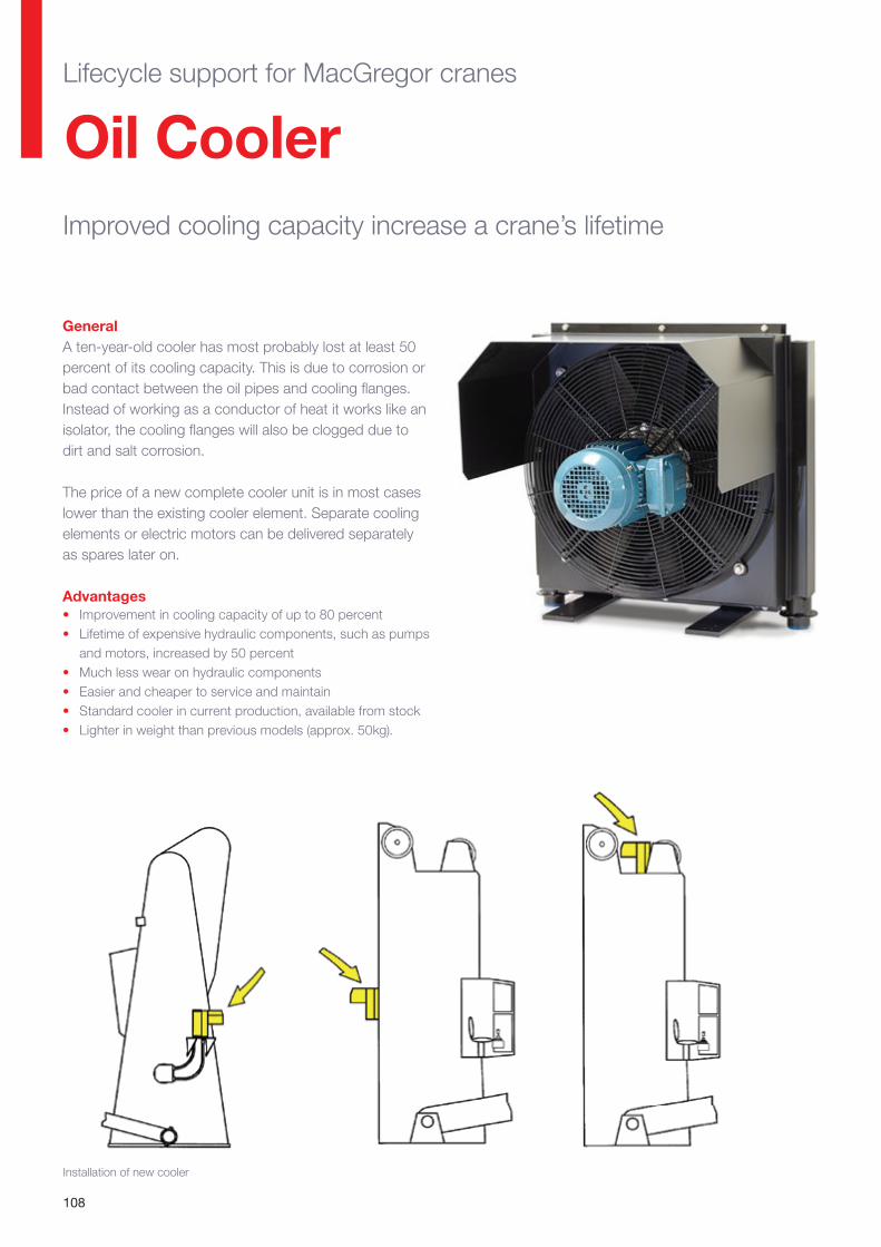
108
GeneralA ten-year-old cooler has most probably lost at least 50 percent of its cooling capacity. This is due to corrosion or bad contact between the oil pipes and cooling flanges. Instead of working as a conductor of heat it works like an isolator, the cooling flanges will also be clogged due to dirt and salt corrosion.
The price of a new complete cooler unit is in most cases lower than the existing cooler element. Separate cooling elements or electric motors can be delivered separately as spares later on.
Advantages• Improvement in cooling capacity of up to 80 percent• Lifetime of expensive hydraulic components, such as pumps
and motors, increased by 50 percent• Much less wear on hydraulic components• Easier and cheaper to service and maintain• Standard cooler in current production, available from stock• Lighter in weight than previous models (approx. 50kg).
Oil CoolerImproved cooling capacity increase a crane’s lifetime
Installation of new cooler
Lifecycle support for MacGregor cranes
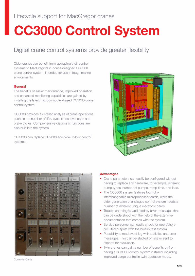
109
Older cranes can benefit from upgrading their control systems to MacGregor’s in-house designed CC3000 crane control system, intended for use in tough marine environments.
GeneralThe benefits of easier maintenance, improved operation and enhanced monitoring capabilities are gained by installing the latest microcomputer-based CC3000 crane control system.
CC3000 provides a detailed analysis of crane operations such as the number of lifts, cycle times, overloads and brake cycles. Comprehensive diagnostic functions are also built into the system.
CC 3000 can replace CC2000 and older B-box control systems.
CC3000 Control SystemDigital crane control systems provide greater flexibility
Advantages• Crane parameters can easily be configured without
having to replace any hardware, for example, different pump types, number of pumps, ramp time, and load.
• The CC3000 system features four fully-interchangeable microprocessor cards, while the older generation of analogue control system needs a number of different unique electronic cards.
• Trouble-shooting is facilitated by error messages that can be understood with the help of the extensive documentation that comes with the system.
• Service personnel can easily check for open/short-circuited outputs with the built-in test system.
• Possibility to read event log with statistics and error messages. This can be studied on site or sent to experts for evaluation.
• Twin cranes can gain a number of benefits by from having a CC3000 control system installed, including improved cargo control in twin operation mode.
Controller Cards
Lifecycle support for MacGregor cranes
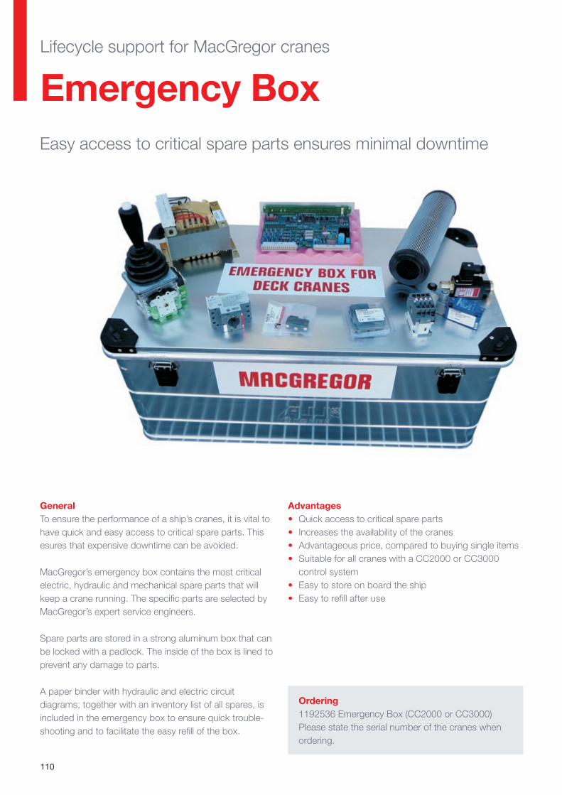
110
GeneralTo ensure the performance of a ship’s cranes, it is vital to have quick and easy access to critical spare parts. This esures that expensive downtime can be avoided.
MacGregor’s emergency box contains the most critical electric, hydraulic and mechanical spare parts that will keep a crane running. The specific parts are selected by MacGregor’s expert service engineers.
Spare parts are stored in a strong aluminum box that can be locked with a padlock. The inside of the box is lined to prevent any damage to parts.
A paper binder with hydraulic and electric circuit diagrams, together with an inventory list of all spares, is included in the emergency box to ensure quick trouble-shooting and to facilitate the easy refill of the box.
Emergency BoxEasy access to critical spare parts ensures minimal downtime
Advantages• Quick access to critical spare parts• Increases the availability of the cranes• Advantageous price, compared to buying single items• Suitable for all cranes with a CC2000 or CC3000
control system• Easy to store on board the ship• Easy to refill after use
Ordering1192536 Emergency Box (CC2000 or CC3000) Please state the serial number of the cranes when ordering.
Lifecycle support for MacGregor cranes
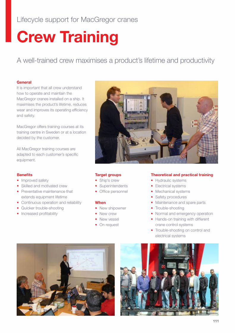
111
GeneralIt is important that all crew understand how to operate and maintain the MacGregor cranes installed on a ship. It maximises the product’s lifetime, reduces wear and improves its operating efficiency and safety.
MacGregor offers training courses at its training centre in Sweden or at a location decided by the customer.
All MacGregor training courses are adapted to each customer’s specific equipment.
Benefits• Improved safety• Skilled and motivated crew• Preventative maintenance that
extends equipment lifetime• Continuous operation and reliability• Quicker trouble-shooting• Increased profitability
Target groups• Ship’s crew• Superintendents• Office personnel
When• New shipowner• New crew• New vessel• On request
Crew TrainingA well-trained crew maximises a product’s lifetime and productivity
Theoretical and practical training• Hydraulic systems• Electrical systems• Mechanical systems• Safety procedures• Maintenance and spare parts• Trouble-shooting• Normal and emergency operation• Hands-on training with different
crane control systems• Trouble-shooting on control and
electrical systems
Lifecycle support for MacGregor cranes
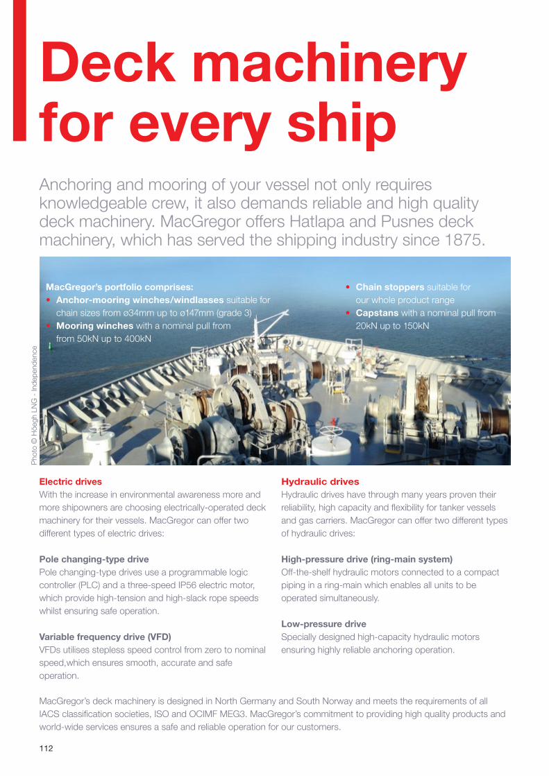
112
Pho
to ©
Höe
gh L
NG
- In
depe
nden
ce
Electric drivesWith the increase in environmental awareness more and more shipowners are choosing electrically-operated deck machinery for their vessels. MacGregor can offer two different types of electric drives:
Pole changing-type drivePole changing-type drives use a programmable logic controller (PLC) and a three-speed IP56 electric motor, which provide high-tension and high-slack rope speeds whilst ensuring safe operation.
Variable frequency drive (VFD)VFDs utilises stepless speed control from zero to nominal speed,which ensures smooth, accurate and safe operation.
MacGregor’s deck machinery is designed in North Germany and South Norway and meets the requirements of all IACS classification societies, ISO and OCIMF MEG3. MacGregor’s commitment to providing high quality products and world-wide services ensures a safe and reliable operation for our customers.
MacGregor’s portfolio comprises:• Anchor-mooring winches/windlasses suitable for
chain sizes from ø34mm up to ø147mm (grade 3)• Mooring winches with a nominal pull from
from 50kN up to 400kN
• Chain stoppers suitable for our whole product range
• Capstans with a nominal pull from 20kN up to 150kN
Deck machinery for every shipAnchoring and mooring of your vessel not only requires knowledgeable crew, it also demands reliable and high quality deck machinery. MacGregor offers Hatlapa and Pusnes deck machinery, which has served the shipping industry since 1875.
Hydraulic drivesHydraulic drives have through many years proven their reliability, high capacity and flexibility for tanker vessels and gas carriers. MacGregor can offer two different types of hydraulic drives:
High-pressure drive (ring-main system)Off-the-shelf hydraulic motors connected to a compact piping in a ring-main which enables all units to be operated simultaneously.
Low-pressure driveSpecially designed high-capacity hydraulic motors ensuring highly reliable anchoring operation.
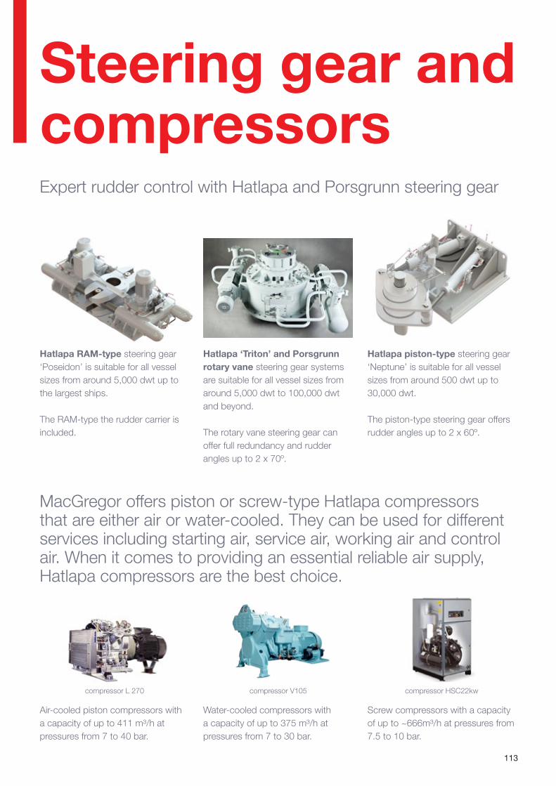
113
Hatlapa RAM-type steering gear ‘Poseidon’ is suitable for all vessel sizes from around 5,000 dwt up to the largest ships.
The RAM-type the rudder carrier is included.
Hatlapa ‘Triton’ and Porsgrunn rotary vane steering gear systems are suitable for all vessel sizes from around 5,000 dwt to 100,000 dwt and beyond.
The rotary vane steering gear can offer full redundancy and rudder angles up to 2 x 70º.
Hatlapa piston-type steering gear ‘Neptune’ is suitable for all vessel sizes from around 500 dwt up to 30,000 dwt.
The piston-type steering gear offers rudder angles up to 2 x 60º.
MacGregor offers piston or screw-type Hatlapa compressors that are either air or water-cooled. They can be used for different services including starting air, service air, working air and control air. When it comes to providing an essential reliable air supply, Hatlapa compressors are the best choice.
Air-cooled piston compressors with a capacity of up to 411 m³/h at pressures from 7 to 40 bar.
Screw compressors with a capacity of up to ~666m³/h at pressures from 7.5 to 10 bar.
Water-cooled compressors with a capacity of up to 375 m³/h at pressures from 7 to 30 bar.
compressor L 270 compressor V105 compressor HSC22kw
Steering gear and compressorsExpert rudder control with Hatlapa and Porsgrunn steering gear

Notes

115

Wherever needed, you can rely on our support.
MacGregor shapes the offshore and marine industries by offering world-leading engineering solutions and services with a strong
portfolio of MacGregor, Hatlapa, Porsgrunn, Pusnes and Triplex brands. Shipbuilders, owners and operators are able to optimise
the lifetime profitability, safety, reliability and environmental sustainability of their operations by working in close cooperation with
MacGregor.
MacGregor solutions and services for handling marine cargoes, vessel operations, offshore loads, crude/LNG transfer and offshore
mooring are all designed to perform with the sea. www.macgregor.com
MacGregor is part of Cargotec. Cargotec’s (Nasdaq Helsinki: CCBV) sales in 2015 totalled approximately EUR 3.7 billion and it
employs over 11,000 people. www.cargotec.com
Published by MacGregor. Copyright © MacGregor August 2016. All rights reserved. No part of this publication may be reproduced,
stored, photocopied, recorded or transmitted without permission of the copyright owner.
MacGregor Cargo Handling [email protected]@macgregor.comwww.macgregor.com