capital trail – varina phase henrico county virginia ... trail – varina phase henrico county...
TRANSCRIPT
Capital Trail – Varina Phase
Henrico County
Virginia
Geotechnical Engineering Data Report
Project No. 0005-043-714
PPMS No. 86280
Virginia Department of Transportation
October 3, 2012

VDOT Project No 0005-043-714 October 3, 2012 Virginia Capital Trail Project – Varina Phase
TABLE OF CONTENTS
1.0 INTRODUCTION ................................................................................................ 1 2.0 PROJECT DESCRIPTION .................................................................................. 1 3.0 SITE DESCRIPTION .......................................................................................... 1 4.0 GEOLOGIC MAPPING ...................................................................................... 1 5.0 FIELD EXPLORATION...................................................................................... 2 6.0 SUBSURFACE CONDITIONS ........................................................................... 3
6.1 Generalized Subsurface Conditions .................................................................. 3 6.2 Ground Water ................................................................................................... 3
7.0 PAVEMENTS ...................................................................................................... 3 7.1 Minimum Pavement Sections ........................................................................... 3
8.0 GEOTECHNICAL ENGINEERING CONSIDERATIONS DURING DESIGN AND CONSTRUCTION ................................................................................................ 4
8.1 Earthwork ......................................................................................................... 5 8.2 Slope Design ..................................................................................................... 5 8.3 Unsuitable Materials ......................................................................................... 6 8.4 Drainage Structures .......................................................................................... 8
9.0 LIMITATIONS .................................................................................................... 8 Appendix ....................................................................................................................... 10 • Plan View of Borings • VDOT Boring Log Legend/Symbol List • Boring Logs • Bridge Borings

VDOT Project No 0005-043-714 October 3, 2012 Virginia Capital Trail Project – Varina Phase
1
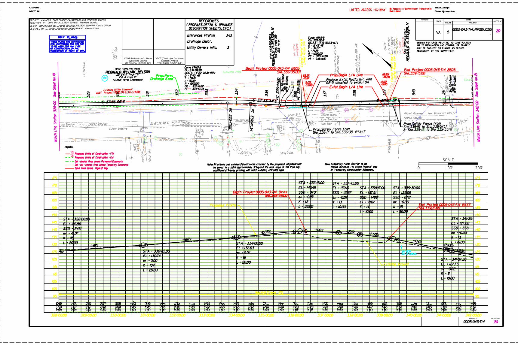
1.0 INTRODUCTION The purpose of this data report is to present the results of the preliminary subsurface exploration performed by the Virginia Department of Transportation (VDOT) to prospective design-builders for the Virginia Capital Trail project (Varina Phase) Design-Build project, in order for them to have a uniform basis for preparation of proposals. The scope of work includes but is not limited to, construction of embankments, paved asphalt multiuse path consisting of asphalt, and bridges in the vicinity of Route 5. Limitations on use of this report and the geotechnical data provided herein are discussed in Section 9.0. 2.0 PROJECT DESCRIPTION The Project is located in Henrico County, Virginia, and includes the design and construction of the Virginia Capital Trail between Rocketts Landing and Longbridge Road in Charles City County. The Trail will be located parallel to Route 5. The Trail will be a 10 feet wide full depth asphalt pavement structure throughout the project limits unless otherwise noted in the preliminary design plans included in the RFP Information Package. The total length for the Varina Phase of the Virginia Capital Trail is approximately 10.8 miles. Right of way acquisition and utility relocation activities will be the responsibility of the Design-Builder. 3.0 SITE DESCRIPTION The area of the proposed project is rural in nature. The path will traverse moderately wooded areas with intermittent residential and commercial driveway/entrances. Additionally, bridges are scoped to traverse the following: Almond Creek {04BH-001 and 04BH-002}, Four Mile Creek {12BH-003}, and Cornelius Creek {12BH-004}. Plans imply proposed drainage work as follows: 36.0 inch pipe {12BH-006}, box culvert extension {12BH-007}, and 60.0 inch pipe {12BH-008}. There are numerous underground and overhead utilities on both sides of Route 5. 4.0 GEOLOGIC MAPPING This section of Route 5 is located within the western boundary of the Coastal Plain, a Quarternary aged accumulation of sediments which extends from Maryland to North Carolina. The Coastal Plain was created during transgression and regression of the Atlantic Ocean associated with changes of sea levels during Ice Age events and consists, within the area of the proposed project, primarily of soils (Shirley Formation) that are interbedded gravel, sand, silt, clay, and peat; at altitudes to 35-45 ft. deposited on soils (Charles City Formation) that are interbedded sand, silt, clay and minor gravel; at

VDOT Project No 0005-043-714 October 3, 2012 Virginia Capital Trail Project – Varina Phase
2
altitudes to 70-80 ft. As a result of these processes, two main types of soil, and their weathered constituents, can be anticipated within the project limits:
Chuckatuck Formation – “Coastal Plain From expanded explanation (ref. VA002): Chuckatuck Formation (middle(?) Pleistocene, Johnson and Berquist, 1989). Light- to medium-gray, yellowish-orange, and red dish-brown sand, silt, and clay and minor amounts of dark-brown and brownish-black peat. Comprises surficial deposits of mid-level coast-parallel plains (altitude 50-60 feet) and equivalent riverine terraces. Eastward, unit is truncated by the Suffolk scarp; westward, along major stream drainages, unit is separated from the younger topographically lower Shirley Formation by the Kingsmill scarp and equivalent estuarine scarps. Fluvial-estuarine facies includes, from bottom to top, (1) channel-fill deposits of poorly sorted, cross-bedded, pebbly and cobbly sand interbedded, locally, with peat and sandy silt rich in organic matter, (2) moderately well-sorted, cross-bedded to planar bedded, fine- to medium-grained sand grading up ward into (3) clayey silt and sandy and silty clay. Bay facies of coastwise plain includes a basal gravelly sand filling shallow paleochannels, a thin but extensive pebbly sand containing heavy mineral laminae and Ophiomorpha burrows, and an upper, relatively thick, medium- to fine-grained silty sand and sandy silt. Thickness is 0 to 26 feet.” (U.S. Department
of the Interior, 2007)1
5.0 FIELD EXPLORATION The field exploration for this project was performed on February, 2012. Subsurface conditions were explored by drilling a total of 5 standard penetration test (SPT) borings in accordance with ASTM D 1586. The boring logs are included in the Appendix Section. The boring numbering was not in sequential fashion. The proposed borings were staked by referencing landmarks on plan sheets and the GPS coordinates were verified via hand-held GPS. The borings are not numbered sequentially due to elimination of proposed borings due to limited access. Additional borings used in project 0895-043-F01 are included in the Appendix Section. Additionally, a boring location plan of the SPT locations is included in Appendix Section. Soil descriptions on the boring records are visual and are generally in accordance with the Unified Soil Classification System (USCS) as described in ASTM D 2487 and ASTM D 2488.
1 U.S. Department of the Interior. (2007, April 4). Retrieved December 9, 2011, from U.S. Geological Survey: http://tin.er.usgs.gov/geology/state/sgmc-unit.php?unit=VAQc;0

VDOT Project No 0005-043-714 October 3, 2012 Virginia Capital Trail Project – Varina Phase
3
All SPT soil samples are available for inspection at the office of the Richmond District Materials Engineer, 2430 Pine Forest Drive, Richmond, Virginia 23834. Please call Mr. Harold Dyson, P.E. at (804) 524-6211 to obtain access to the samples. 6.0 SUBSURFACE CONDITIONS 6.1 Generalized Subsurface Conditions
We have characterized the following generalized subsurface soil stratigraphy based on the boring data presented in Appendix Section. Topsoil. Topsoil was observed to be 2.0 ft thick at boring 04BH-001. Recommend the thickness of topsoil at 12” (300 mm) for estimating purposes for stripping depths. The estimate is based on information from VDOT Project 0005-018-114. Coastal Plain Sediments (Chuckatuck Formation). This stratum generally consist of very loose to dense cohesionless soils and very soft to stiff cohesion soils. The soils encountered within the upper 5 ft (1.5m) of the ground surface in borings 04BH-001 12BH-004, 12BH-006, 12BH-007, and 12BH-008, consisted of very soft to soft consistency fine-grained soils and/or very loose to loose density coarse-grained soils. Weight of hammer (WOH) material was encountered in the upper 10.0 ft (3.0 m) zone within borings 12BH-003. Very dense material was encountered at depths ranging from 53.0 ft (16.2 m) – 108.8 ft (33.2 m). 6.2 Ground Water For SPT borings, groundwater was first encountered at EL ranging from 17.4 – 128.9 ft. Long term ground water measurements were not recorded. Fluctuations of the ground water levels shown on the boring logs should be expected with changes in precipitation, stream levels, surface run-off and evaporation. 7.0 PAVEMENTS 7.1 Minimum Pavement Sections If the Design-Builder confirms that the minimum pavement sections are inadequate for actual design/construction conditions, it shall notify VDOT during the Scope Validation Period of the necessary changes and proposed price adjustments, if any. Acceptable changes are limited to increasing the thickness of the base or subbase layers specified below. Any changes to the minimum pavement sections noted above must be approved by VDOT prior to implementation. The Design-Builder shall be responsible for the final

VDOT Project No 0005-043-714 October 3, 2012 Virginia Capital Trail Project – Varina Phase
4
design and construction of the pavements for this Project as approved by VDOT and in accordance with the Contract Documents. The Design-Builder shall prepare and incorporate the validated pavement sections into the plans, typical sections, profiles and cross-sections in accordance with the applicable manuals noted in Section 2.1.1 of this document. This includes drainage and subdrainage requirements to ensure positive drainage both within the pavement structure and on the pavement surface. The minimum pavement sections for the project are as follows:
Virginia Capital Trail 2.0 inches of Asphalt Concrete SM-12.5A (estimated 220 lb/sy) 8.0 inches of Coarse Aggregate, Size No. 8, Aggregate Base Material, Type I, Size No. 21B, or RAP (RAP of comparable gradation is acceptable when consistent with Special Provision for Crushed Hydraulic Cement Concrete, with respect to Acceptance criteria.) Geosynthetics and free-draining material shall be used for stabilization and drainage at the discretion of the Design Manager. Approximate locations requiring geosynthetics may be interpolated from the data included in the preliminary geotechnical study that is provided in the RFP Information Package. These locations shall be verified in the final geotechnical report provided by the Design-Builder and any discrepancies must be reported to VDOT prior to the expiration of the Scope Validation Period. Entrances PE-1 TYPE I/III 2.0 inches of Asphalt Concrete SM-12.5A (estimated 220 lb/sy) 6.0 inches of Aggregate Base Material, Type I, Size No. 21B or RAP of comparable gradation PE-1 TYPE IV 4.0 inches of Asphalt Concrete SM-12.5A (estimated 220 lb/sy X 2 lifts) 4.0 inches of Asphalt Concrete BM-25.0A (estimated 440 lb/sy) 8.0 GEOTECHNICAL ENGINEERING CONSIDERATIONS DURING DESIGN AND CONSTRUCTION In addition to the presentation of subsurface exploration and soil laboratory testing data, an objective of this report is also to discuss in general terms pertinent geotechnical issues that should be considered during the design and construction of this project.
VDOT Project No 0005-043-714 October 3, 2012 Virginia Capital Trail Project – Varina Phase
5
8.1 Earthwork Preliminary grading plans indicate that moderate to extensive cut and fill will be required on this project. Earthwork issues that should be considered during design include, but are not limited to, subgrade preparation, subdrainage, compacted fill placement, slope benching, allowable cut and fill slope angles, evaluation of stability and settlement in both design and construction for non-retained fills, both existing and proposed, throughout the project. It will be the design-builder’s responsibility to synthesize a reasonable analysis of the stability and settlements of the embankments that have been designed to the minimum tolerances specified in the RFP for this project. The impact of settlement on the overall construction of the embankments must be determined during design and an appropriate monitoring system is required as stipulated in Section 2.5. For subgrades, it will be important to address topsoil stripping, appropriate methods for evaluation of subgrade suitability, and procedures for mitigating unsuitable subgrade materials. With respect to subdrainage, the design-builder should identify areas where subdrainage is needed beyond that required by the standard VDOT specifications/special provisions and design the appropriate types of subdrainage. The design-builder should evaluate the suitability of on-site soils for use as fill or backfill with respect to soil types and moisture contents as discussed in Section 10.3, below. Accordingly, moisture conditioning of the on-site soils should be anticipated and considered in design and construction of this project. Therefore, it will be important that the design-builder address the potential impact that these soils could have on earthwork operations and how they should be treated during construction. As an alternative to aeration and/or mechanical drying, the design-builder may elect to use pelletized quick lime to dry soils that are excessively wet provided dust is adequately controlled. 8.2 Slope Design Cut and fill slopes shall be no steeper than 2H:1V unless supported by engineering analyses based on site specific field investigation and site specific laboratory strength testing. Slopes steeper than 2H:1V must be approved by the Department. The following factors of safety are to be used with limit equilibrium methods of analysis to determine factors of safety for representative sections of all soil cut and soil embankment fill slope areas greater than 10 ft (3.0 m) in height and/or where slopes are supporting, or are supported by, retaining structures. The factors of safety listed in Table 1 below are valid for subsurface investigations performed in accordance with Chapter III of the Materials Division’s Manual of Instructions or for site specific investigation plans approved by the District Materials Engineer. Approval of site specific investigation plans with reduced boring frequency may require higher factors of safety.

VDOT Project No 0005-043-714 October 3, 2012 Virginia Capital Trail Project – Varina Phase
6
Table 1: Minimum Factors of Safety for Soil Cut/Fill Slopes
Slope analysis parameters based on: Factor of Safety Involves Structure or
Critical Slope1,4 Non-Critical Slope
In-situ or lab. tests and measurements2,3 1.5 1.3 No site specific tests N/A3 1.5
Notes: 1. A critical slope is defined as any slope that is greater than 25’ in height, affects or supports a
structure, impounds water or whose failure would result in significant cost for repair, or damage to private property
2. Site specific in-situ tests include both ground water measurements and SPT testing but may also include CPT or DMT
3. Parameters for critical slopes involving structures must be based on specific laboratory testing 4. Problem soils (very soft and very loose soils, fissured or heavily over-consolidated soils), must be
analyzed using shear strength parameters determined from appropriate laboratory strength tests in accordance with accepted local engineering practice
5. Construction plans shall specify use of soil types consistent with the parameters used in slope analyses
8.3 Unsuitable Materials Unsuitable materials are defined under Section 101.02 of Part 5 of the RFP document as: Any material for use as embankment fill, and in cut areas to a depth of at least 3 ft below subgrade directly beneath pavements and at least 2 ft beneath the bedding of minor structures and laterally at least 2 ft beyond the outside edge of the pavement shoulders and bedding limits of the minor structures that classify as CH, MH, OH and OL in accordance with the Unified Soil Classification System (USCS),that contains more than 5 percent by weight organic matter, that exhibits a swell greater than 5 percent as determined from the California Bearing Ratio (CBR) test using VTM-8, and that exhibits strength, consolidation, durability of rock or any other characteristics that are deemed unsuitable by the Design-Builders’ geotechnical engineer or as denoted in the Contract Documents for use in the Work. Saturated or very dry and/or loose or very soft coarse- and fine-grained soils that exhibit excessive pumping, weaving or rutting under the weight of construction equipment are also considered unsuitable unless they can be moisture conditioned through either mechanical or chemical means to an acceptable moisture content that allows adequate compaction to meet project specifications, and classification testing indicates they are not otherwise unsuitable. Topsoil, peat, coal and carbonaceous shale shall also be considered unsuitable material. All unsuitable material shall be disposed of and/or treated as discussed in Section 106.04 at no cost to the Department. Acceptable methods of handling these unsuitable materials are outlined in Section 106.04 of Part 5 of the RFP document as follows:

VDOT Project No 0005-043-714 October 3, 2012 Virginia Capital Trail Project – Varina Phase
7
The Design-Builders’ geotechnical engineer shall confirm that slopes, earthwork,
pavement, and foundation subgrades satisfy the design and Contract Document requirements. The Design-Builders’ geotechnical engineer shall perform an inspection of all embankment and pavement subgrades and minor structure excavations immediately prior to placement of embankment fill, aggregate base, subbase or bedding materials to identify excessively soft, loose, dried or saturated soils that exhibit excessive pumping, weaving or rutting under the weight of the construction equipment. Such materials are considered unsuitable and must be removed or modified in place to provide adequate support for embankment, pavement subgrade or minor structures. Materials unsuitable for use in the Work shall be disposed of at an approved Disposal Area or landfill licensed to receive such Material unless the materials can be adequately treated in place through pre-approved methods of chemical and/or mechanically stabilization to satisfy the design and Contract Document requirements. All Unsuitable Materials shall be disposed of off-site and/or treated in place at no cost to the Department. Unsuitable Materials and methods of treatment shall be identified on the plans and cross sections.
The design-builder’s qualified geotechnical engineer shall perform an inspection of all pavement subgrades and minor structure excavations immediately prior to placement of aggregate base, subbase or bedding materials to identify excessively soft or saturated soils that exhibit excessive pumping, weaving or rutting under the weight of the construction equipment in accordance with the requirements outlined in Part 5 of the RFP document. Such soils are also considered unsuitable and must be removed or modified in place to provide adequate support for embankment, pavement subgrade or minor structures. The following table demonstrates potential areas of unsuitable material based on borings presented in Section 6.1 Generalized Subsurface Conditions: Table 1. Potential Areas of Unsuitable Materials
Boring Latitude Longitude Depth Range (ft) Soft or loose soil 04BH-001 37.50641836 77.41183547 5.5 – 15.5 04BH-002 37.50662637 77.41210416 5.5 – 15.5 12BH-003 37.432655 77.325071 0.0 – 3.0; 7.0 – 15.0; 20.0 – 25.0 12BH-004 37.465382 77.382426 0.0 – 5.5 12BH-006 37.430305 77.314204 0.0 – 6.0 12BH-007 37.459615 77.377074 0.0 – 15.0 12BH-008 37.474961 77.390188 5.0 – 15.0
The table above presents potential areas of unsuitable materials with respect to criteria defined in the RFP. The loose (N <11) or soft (N<5) characterization is based on N-value of SPT counts.
VDOT Project No 0005-043-714 October 3, 2012 Virginia Capital Trail Project – Varina Phase
8
8.4 Drainage Structures The design-builder should consider subsurface conditions in order to design adequate and uniform support for the proposed pipe culverts in order to limit total and differential settlements to meet the criteria specified in the RFP. The design-builder should also consider the chemical testing (pH and resistivity) when selecting allowable pipe materials. 9.0 LIMITATIONS This report has been prepared to facilitate preparation of proposals for this project and should not be solely relied upon for the final design and construction of this project. A design level geotechnical investigation must be performed by the design-builder to verify and augment the information included in this report including those investigations specified by the Request for Proposals (RFP) during the Scope Validation Period. Reference should be made to the other Contract Documents, including the RFP and General Conditions provided with the RFP, for further information regarding required investigations and the identification, resolution and responsibility for differing site conditions. The boring logs included in this report depict the subsurface soil, ground water, and existing pavement conditions at the specific locations where the borings were performed. These conditions may vary at other locations beyond, or between, these specific locations. Accordingly, the Department does not warrant or guarantee that the information provided on the logs, or in this report, can be projected as indicative of conditions beyond the limits of the borings, and any such projection is purely interpretive. In addition, the ground water levels recorded on the boring logs indicate the ground water conditions that existed at the time of the investigation. Ground water levels may vary considerably, with time, according to prevailing climate, rainfall, surface run-off, evaporation, construction and other factors. The boring logs are made available to bidders in order that they may have access to subsurface data identical to that which is possessed by the Department, and are not intended as a substitute for personal investigation, interpretation and judgment by others. Also, the information contained herein represents borings that were performed by the Department and may not represent all of the borings performed on the project, particularly if consultant designers performed work under self contained geotechnical/design contracts. The minimum pavement sections and discussion of geotechnical considerations as presented in this report are based on the information revealed by our exploration. We

VDOT Project No 0005-043-714 October 3, 2012 Virginia Capital Trail Project – Varina Phase
9
have attempted to provide for normal contingencies, but the possibility remains that unexpected conditions may be encountered during subsequent site explorations and construction. The design-builder must perform additional test borings and laboratory testing to develop the design for this project and to meet the minimum requirements outlined in Chapter 3 of the current VDOT Material Division’s Manual of Instructions and the current AASHTO LRFD Bridge Design Specifications, 2007; 2008 Interim Specifications; and VDOT Modifications. We have endeavored to complete the services identified herein in a manner consistent with that level of care and skill ordinarily exercised by members of the profession currently practicing in the same locality and under similar conditions as this project.

VDOT Project No 0005-043-714 October 3, 2012 Virginia Capital Trail Project – Varina Phase
10
Appendix

130+00.00 135+00.00126+00.00 127+00.00 128+00.00 129+00.00 131+00.00 132+00.00 133+00.00 134+00.00 136+00.00 137+00.00
15
20
25
30
35
40
45
50
55
60
65
70
75
80
85
15
20
25
30
35
40
45
50
55
60
65
70
75
80
85
140+00.00137+00.00 138+00.00 139+00.00
60
65
70
75
80
85
90
95
100
105
110
115
120
125
130
60
65
70
75
80
85
90
95
100
105
110
115
120
125
130
d86280005.dgn
Plotted By: alex.taloma2:48:44 PM
10/2/2012
d86280005.dgn
Plotted By: alex.taloma2:48:44 PM
10/2/2012
PROJECT MANAGER
SURVEYED BY
DESIGN SUPERVISED BY
DESIGNED BY
VA.
STATE
ROUTE PROJECT
VA.
REVISEDSTATE
STATE
ROUTE PROJECTSHEET NO.
DESIGN FEATURES RELATING TO CONSTRUCTION
OR TO REGULATION AND CONTROL OF TRAFFIC
MAY BE SUBJECT TO CHANGE AS DEEMED
NECESSARY BY THE DEPARTMENT
PROJECT SHEET NO.
(TECHNICAL DISCIPLINE)
(Location), Virginia
VDOT (Division) or Co. Name
(TECHNICAL DISCIPLINE)
(Location), Virginia
VDOT (Division) or Co. Name
5 50005-043-714, RW201, C501
Matc
h Lin
e Station 14
0+0
0.0
0 See Sheet
No. 6
Matc
h Lin
e Station 12
6+0
0.0
0 See Sheet
No. 4
Kevin Reichert, P.E. (804) 524-6153 (Richmond District)
David Burch, L.S. (804) 524-6157 (Richmond District)
Vernon Heishman, P.E. (804) 225-4310 (Central Office)
Larissa Tachmetova (804) 786-8387 (Central Office)
0 100’ 200’
SCALE
9A
10
5
10
5
0005-043-714 5
Drainage Descr.
Entrances Profile
REFERENCES
( PROFILES, DETAIL & DRAINAGE
DESCRIPTION SHEETS, ETC. )
Reverse Crown 2%Normal Crown -2%
THESE PLANS ARE UNFINISHED
AND UNAPPROVED AND ARE NOT
TO BE USED FOR ANY TYPE
OF CONSTRUCTION OR THE
ACQUISITION OF RIGHT OF WAY.
RFP PLANS
-2% - 2%: Reverse Crown 2%
Existing Ground
Existing Ground
Proposed Profile
Proposed Profile
Solid lines denote Right of Way
Dot - dot - dashed lines denote Temporary Easements
Dot - dashed lines denote Permanent Easements
C
FProposed Limits of Construction - Fill
Proposed Limits of Construction - Cut
Legend:
Note:
Temporary Construction Easement.
Temporary Filter Barrier to be placed minimum 1 ft within Right of Way or
Utility Owners Info. 3
Note:
additional driveway grading will match existing entrance type.
be paved to a point approximately 3’ beyond the back edge of the trail. Any
All private and commercial entrances crossed by the proposed alignment will
T-3
VD
OT
Contr
ol Station
Mon. 43-0
522
T-5
VD
OT
Contr
ol Station
Mon. 43-0
520
T-6
Nail
UD
FL
Ele
v 24.3
3
Ele
v 9.2
6
Top
Of
Water
Rip Rap
Asphalt E
nt.
In Pl. 15" C
onc. Pip
e
IP
R/
W
Mon.
Inv In Ele
v 34.6
0
Inv Out Ele
v 33.8
3
+62.6
7
8.6
1’
+49.17
28.7
1’
IP
Inv In Ele
v 57.0
0
Pipe C
ontinu
esIn Pl. 18" C
onc. Pip
e
Pump StationAlmond Creek
Top
Of
Water
Ele
v 9.3
1
UD
Ele
v 25.4
5
(Rte 5)
+96.0
2
205.7
7’
Woven
Wire Fence
Asphalt Pavement Old Osborne Tpke. Asphalt Pavement Old Osborne Tpke.
Chain Lin
k Fence
Woven
Wire Fence
PI 521+73.7
0
S 14° 26’ 02" E
S 29° 30’ 21" E
S 25° 16’ 51" E515
520
FL
Alm
ond
Creek
Conc.
Wall
Bridge
Conc Pier
Conc Pier
Asph Sh.
Asph Sh.
Rip Rap
IP+6
8.0
3
205.17’
Asphalt D
eck
Prop.
Mon.
Pinch Pipe
+47.50
28.41’
+23.18
62.8
0’
Conc.
Wall
Metal
Guardrail
Survey Baseline Survey Baseline
Survey Baseline Survey Baseline
( N 60°5
1’15
" E 18
2.9
9’ )
( S 65°12’3
0"
W 19
5.3
7’ )
( S 24°47’30" E 125.43’ )
26.72’)
( S 24°47’30" E
( N 24°47’30" W 130.84’ )
( S 65°12’3
0"
W 19
5.3
7’ )
118.71’)
( S 31°02’00" E
PL
PL
PL
32. 0
8’ )
(S30°17’2
3"E
100.00’)
(S24°34’45"E
100.50’)
(S18°52’05"E
On Proj. #146-43-1221-D Exist. R/W Based
20" T
win
Oak
20"
Oak
Sig
n
Paved
Ditch
Conc. Driv
e
Gravel
Drive
Sig
n
Sig
n
Sig
n
Sig
n
Sig
n
Sig
n
Sig
n
Gravel
Asphalt Drive
Sig
n
Sig
n
Sig
n
Pave
d Ditch
Rip Rap
2.5’ C
&G
2.5’ C
&G
Rip Rap
Rip Rap
w/Heavy Underbrush
Medium Woods
Security Ca
mera
4’ Chainlink4’ Chainlink
(N82°4
7’0
0"W 10
0.00’)
(98.2
7’)
(N82°4
7’0
0"W)
(S07°13’00"W 194.65’)
(23.42’)
(N50
°53’53
"W)
(35.20’)
(N07°46’00"E)
(N07°45’00"E 492.00’)
1 2
3
4
5
(7.62’)
(N21°14’01"W)
6
(N60°4
5’16"E 17
7.8
3’)
(S01°02’50"W 402.81’)
(N18°31’23"W 118.71’) (N24°48’36"W 200.00’)
(32.0
0’)
(N69°5
7’10"E)
(N20°02’50"W 99.39’) (N20°30’30"W 110.70’)
(N20°30’30"W 110.70’) (N20°30’30"W 295.31’)
(S85°0
3’4
5"E 355.81’)
65.14’
+05.95
IRF
152.75’+63.54IRF
29.52’+51.64IRF
49.04’+97.70IPF
67.95’
+14.40
IPF
21.47’
+53.42
RM-1
53.49’+56.00IRF
18.15’
+61.53
IRF
164.26’+44.92IRF
Mediu
m
Underbrush
Lig
ht
Woods
Light Woods
Medium Underbrush
Light Woods
Asphalt R
oad
way
McCoul Street
Asphalt Drive
Inv.
Out 48.0
8
Inv. In 53.3
3
In Pl. 18"
RCP
N0°35’43"E 194.63’
S89°2
4’0
1"E 99.87’
PLPL
PL
PL
PL
PL
Inv Out 70.2
3’
Inv. In 72.5
3’
w/
Conc. H
ead
walls
In Pl. 18"
RCP
4’
Weld
ed
Wire
4’
Weld
ed
Wire
8’ Chain Lin
k
Rip Rap
Sig
n
Inv.
Out 23.7
3
Inv. In
Unable to locate
In Pl. 6
" CP
VC
PL
(20’)(2
14’)
(199’)
(237’)
&
R.R.
Crossin
g Sig
n
R.R.
Mile
Marker C
A 82.3
2
225
S24°38’09"E
=2
9°0
6’15" Rt.
PI 2
22+4
5.5
1
Noted on Data Sheet .
Note : Bridge Elevations Are
No #
2
Guy
Wires
Tele.
Box
WM
VP # C
D86
VP # C
D98
VP # D
D24
VP # D
D06
2
Guy
Wires
Guy
Wire
Tele
visio
n
Hand
Hole
TV
VP # D
C46
Elec. Transfor
mer
Tele. P
ed. N
o#
Guywire
PP #C
E90
S
T
T
Utility Pole No#
Utility Pole No#
S
2 5
TREE HILL, LLC
DEVELOPMENT COMPANY-
GRAY LAND AND
WWB, LLC
FLOYD E. BURNETTE
JOYCE B. HUBBARD &
COMPANY - TREE HILL, LLCGRAY LAND AND DEVELOPMENT
VIRGINIA
COMMONWEALTH OF
HENRICO, VIRGINIA
COUNTY OF
VULCAN LANDS, INC.
PT 12
5+6
0.11
126
127
128
PC 12
8+3
1.12
PT 12
8+8
0.7
3
129
PC 12
9+2
7.9
5
PT 12
9+7
7.3
5
130
131
PI 131+49.6
3
132
133
PC 13
3+2
9.0
5
PT 13
3+6
2.15
134
PC 13
4+0
1.68
PT 13
4+3
4.7
8
135
PI 135+3
5.6
4
136
137
PC 13
7+4
9.6
2
PT 13
7+9
1.86
138
PC 13
8+0
8.16
PT 13
8+4
7.2
1
139
140
Curve VRN-1-11
PI = 128+55.95
T = 24.83’
L = 49.61’
R = 500.00’
128+31.12PC =
PT = 128+80.73
Curve VRN-1-12
PI = 129+52.67
T = 24.72’
L = 49.40’
R = 500.00’
129+27.95PC =
PT = 129+77.35
Curve VRN-1-13
PI = 133+45.62
T = 16.56’
L = 33.10’
R = 300.00’
133+29.05PC =
PT = 133+62.15
Curve VRN-1-14
PI = 134+18.25
T = 16.56’
L = 33.10’
R = 300.00’
134+01.68PC =
PT = 134+34.78
Curve VRN-1-15
PI = 137+70.78
T = 21.16’
L = 42.24’
R = 300.00’
137+49.62PC =
PT = 137+91.86
Curve VRN-1-16
PI = 138+27.71
T = 19.55’
L = 39.05’
R = 300.00’
138+08.16PC =
PT = 138+47.21
F C C F
FC CF
FC
CF
F C C F
F C CF FC CF
F C C F F C C FF C
Station 126+93.00
Begin Project 0005-043-714 B601
Station 128+24.00
End Project 0005-043-714 B601
Prop. R/WProp. R/WProp. R/W
Temp. Const. Ease.
Drainage Ease.
Prop. Perm.
Prop. Perm. Drainage Ease.
Drainage Ease.
Prop. Perm.
Temp. Const. Ease.
for Entrances
Prop. Temp. Const. Ease.
Prop. Temp. Const. Ease.
from Sta. 128+24 to Sta. 128+72 RT
from Sta. 128+24 to Sta. 128+30 LT
from Sta. 126+80 to Sta. 126+93 RT<
Prop. Safety Fence at footbridge ends:
W=16
’ G=-1.5
5%
Type III
Std. P
E-1 R
eq’d
Easement
Temp. Const.
Begin Section 1 Sta. 126+93.00
Begin Project 0005-043-714
04B
H-0
01
29.0
0
04B
H-0
02
26.5
8
2
4 4
5
DB4250 PG678
531. 7 AC.
Tax# 797-706-5048
2.013 Acres
D.B. 601 Page 85 Plat
D.B. 3706 Page 2056
GPIN #799-708-2466
GPIN #799-708-2079 &
0.80 AcresD.B. 4250 Page 678
GPIN #797-706-5048
8.262 AcresP.B. 116 Page 199
D.B. 4223 Page 2496
GPIN #799-709-0364
A
16.8393 Acres (Assessed)
D.B. 236B Page 131
GPIN #799-710-2548
DB1846 PG471.602 AC.
Tax# 798-709-505751.71 Acres
P.B. 88 Page 47-48
D.B. 3184 Page 1823
GPIN #797-709-8878
STA = 126+50.00
EL = 26.80
+1.80%
L = 20.00
K = 20
ex = 0.03’
STA = 128+00.00
EL = 29.50
+1.80%
+5.59%
L = 68.03
K = 18
ex = 0.32’
STA = 129+05.00
EL = 35.37
+5.59%
+1.80%L = 30.00
K = 8
ex = -0.14’
SSD = 300’
STA = 129+88.00
EL = 36.87
+1.80%
+6.67%
L = 86.00
K = 18
ex = 0.52’
STA = 133+80.00
EL = 63.00
+6.67%
+2.08%L = 40.00
K = 9
ex = -0.23’
SSD = 255’
STA = 134+40.00
EL = 64.25
+2.08%
+5.99%
L = 70.00
K = 18
ex = 0.34’
26.0
3
26.2
4
29.3
0
26.5
2
23.5
9
10.6
3
10.9
8
23.8
0
24.5
8
25.6
8
27.5
4
34.7
2
36.18
35.9
9
36.2
9
37.0
5
38.18
38.8
6
39.7
6
40.5
2
41.84
43.2
3
45.10
47.3
3
49.5
8
51.76
53.5
8
55.4
3
57.3
0
59.2
1
60.9
1
62.18
63.2
2
64.2
4
65.2
2
66.2
4
67.2
8
68.4
3
69.6
4
70.8
5
72.0
7
73.6
9
75.4
0
77.11
78.8
1
26.4
0
26.6
0
26.8
2
27.2
5
27.7
0
28.15
28.6
0
29.0
7
29.8
2
30.9
2
32.3
0
33.6
9
35.0
3
35.7
3
36.19
36.8
9
37.9
4
39.3
4
41.00
42.6
7
44.3
3
46.0
0
47.6
7
49.3
3
51.00
52.6
7
54.3
3
56.0
0
57.6
7
59.3
3
61.00
62.5
4
63.4
2
64.0
5
65.0
2
66.3
5
67.8
4
69.3
4
70.8
4
72.3
3
73.8
3
75.3
3
76.8
2
78.3
2
79.8
2
STA = 138+45.00
EL = 88.50
+5.99%
+1.70%L = 54.00
K = 13
ex = -0.29’
SSD = 279’
80.5
2
82.2
3
84.0
7
85.6
4
86.7
6
86.9
6
87.0
9
87.7
5
88.2
7
88.7
9
89.3
1
89.8
3
81.31
82.8
1
84.3
1
85.8
1
87.2
8
88.3
9
89.0
1
89.4
4
89.8
6
90.2
9
90.7
1
91.14

275+00.00 280+00.00 285+00.00273+00.00 274+00.00 276+00.00 277+00.00 278+00.00 279+00.00 281+00.00 282+00.00 283+00.00 284+00.00 286+00.00
105
110
115
120
125
130
135
140
145
150
155
160
165
170
175
180
185
105
110
115
120
125
130
135
140
145
150
155
160
165
170
175
180
185
d86280016.dgn
Plotted By: alex.taloma11:35:20 AM
9/21/2012
d86280016.dgn
Plotted By: alex.taloma11:35:20 AM
9/21/2012
PROJECT MANAGER
SURVEYED BY
DESIGN SUPERVISED BY
DESIGNED BY
VA.
STATE
ROUTE PROJECT
VA.
REVISEDSTATE
STATE
ROUTE PROJECTSHEET NO.
DESIGN FEATURES RELATING TO CONSTRUCTION
OR TO REGULATION AND CONTROL OF TRAFFIC
MAY BE SUBJECT TO CHANGE AS DEEMED
NECESSARY BY THE DEPARTMENT
PROJECT SHEET NO.
(TECHNICAL DISCIPLINE)
(Location), Virginia
VDOT (Division) or Co. Name
(TECHNICAL DISCIPLINE)
(Location), Virginia
VDOT (Division) or Co. Name
5 160005-043-714, RW201, C501
Matc
h Lin
e Station 273
+00 See Sheet
No. 15
Matc
h Lin
e Station 286+0
0 See Sheet
No. 17
Kevin Reichert, P.E. (804) 524-6153 (Richmond District)
David Burch, L.S. (804) 524-6157 (Richmond District)
Vernon Heishman, P.E. (804) 225-4310 (Central Office)
Larissa Tachmetova (804) 786-8387 (Central Office)
17C
Drainage Descr.
Entrances Profile
REFERENCES
( PROFILES, DETAIL & DRAINAGE
DESCRIPTION SHEETS, ETC. )
0005-043-714 16
Existing Ground
Normal Crown -2%
THESE PLANS ARE UNFINISHED
AND UNAPPROVED AND ARE NOT
TO BE USED FOR ANY TYPE
OF CONSTRUCTION OR THE
ACQUISITION OF RIGHT OF WAY.
RFP PLANS
Proposed Profile
Note:
Temporary Construction Easement.or
placed minimum 1 ft within Right of Way
Temporary Filter Barrier to be
Utility Owners Info. 3
Solid lines denote Right of Way
Dot - dot - dashed lines denote Temporary Easements
Dot - dashed lines denote Permanent Easements
C
FProposed Limits of Construction - Fill
Proposed Limits of Construction - Cut
Legend:
0 100’ 200’
SCALENote:
additional driveway grading will match existing entrance type.
be paved to a point approximately 3’ beyond the back edge of the trail. Any All private and commercial entrances crossed by the proposed alignment will
PI 646+9
9.6
4
PI 652
+77.4
0
S 20° 03’ 20" E
S 11° 28’ 14" E
645
650
655
Asphalt PavementNew Market Rd.(Rte 5)
Asphalt P
ave
ment
Hic
kory Ave.
Well
Br. Dwl.
1 �- Sty.
Survey Baseline
Survey Baseline
Survey Baseline
PL
PLPL
PL
PLPLPL
PLPL
PLPLZ
Z
Z
PL
Gravel
Drive
VDOT Project #1221-A
Existing Right of Way
Light UnderbrushLight Woods
Cultivated FieldCultivated Field Cultivated Field
PL
Inv.
Out 13
3.2
4
Inv. In 13
3.2
9
w/2
Conc.
Win
gwalls
In Pl. 6
0"
RCP
Inv.
Out 13
6.5
8
Inv. In 13
6.8
3
w/
Conc. End
walls
In Pl. 18"
RCP
T
T
PP #P
M13
PP #P
L75
PP #316
F343
PL52
PP #316
F69 P15
1
S
T
T
WE3
WE5
WF1
WF3
WF4
WG1
WG2
WG3
WG4
WG5
WD1
WD2
WD3
WD4
WE2
WE1
WE4
WF2
Wetland "E
"
Wetland "G"
Wetland "F
"
Wetland "D
"
DP-G
1
DP-F
1
DP-E1
DP-D1
GG-3
GG-4
GG-5
DP-1
GG-6
GG-7
GG-8
GG-1
GG-2
ESTATE VENTURES, LLC
REYNOLDS REAL42
42
Tax# 805-6
97-1437
DO
RIS
HAS
KIN
S
BIB
BS
WIL
LIA
M
MC
KIN
LE
Y C
RU
MP JR
C D
E
E
Tax# 805-6
97-1344
Lot 3
AC.
139.739 Acres (Assessed)
Plat Book 63 Page 8
Plat Book 61 Page 73
D.B. 462 Page 214 Plat
D.B. 2771 Page 870
GPIN #805-698-7655
D.B. 278
B
PAge 17
7
200’
Width
VE
PC
O Ease
ment
Prop. R/W
for EntranceTemp. Const. Ease.
Prop. Perm. Drainage Ease.Prop. Perm. Drainage Ease.
Temp. Const. Ease.
Drainage Ease.Prop. Perm.
273
274
275
276
277
278
279
280
281
282
283
284
285
286
PC 286+2
0.16
CF FC CF FC CF
W=14’ G
=-4.7
2%
Type III
Std. P
E-1 R
eq’d
12
BH-0
08
138.8
5
STA = 273+77.47
EL = 139.66
+0.80%
L = 60.00
K = 31
ex = 0.14’
STA = 275+64.87
EL = 141.16
+0.80% -0.58%
L = 30.00
K = 22
ex = -0.05’
SSD = 798’
STA = 277+25.65
EL = 140.22
-0.58% +0.69%
L = 40.00
K = 31
ex = 0.06’
STA = 279+45.00
EL = 141.74
+0.69%+0.80%
L = 10.00
K = 93
ex = 0.00’
STA = 279+65.00
EL = 141.90
+0.80% -1.47%
L = 16.00
K = 7
ex = -0.05’
SSD = 483’
STA = 280+85.00
EL = 140.13
-1.47% +0.57%
L = 60.00
K = 29
ex = 0.15’
STA = 283+00.00
EL = 141.35
+0.57% -0.75%
L = 24.00
K = 18
ex = -0.04’
SSD = 832’
STA = 284+95.00
EL = 139.89
-0.75% +0.54%
L = 34.98
K = 27
ex = 0.06’
+0.54%
140.12
139.5
9
138.6
6
138.0
6
137.9
9
137.5
1
138.8
0
138.8
6
138.7
4
138.9
8
139.2
1
139.3
0
139.7
6
141.85
140.6
9
139.4
1
139.14
139.5
4
140.0
2
140.5
1
140.6
8
139.9
5
139.6
9
139.3
9
138.3
8
139.7
2
139.9
7
140.5
4
139.9
7
139.8
5
140.2
4
140.6
4
141.04
140.9
5
140.6
6
140.3
7
140.3
9
140.7
4
141.08
141.43
141.78
141.39
140.6
5
140.2
6
140.5
0
140.7
8
141.07
141.31
140.9
7
140.6
0
140.2
2
139.9
4
140.18
140.4
5

315+00.00 320+00.00 325+00.00314+00.00 316+00.00 317+00.00 318+00.00 319+00.00 321+00.00 322+00.00 323+00.00 324+00.00 326+00.00 327+00.00 328+00.00
80
85
90
95
100
105
110
115
120
125
130
135
140
145
150
155
160
80
85
90
95
100
105
110
115
120
125
130
135
140
145
150
155
160
d86280019.dgn
Plotted By: alex.taloma11:29:19 AM
9/21/2012
d86280019.dgn
Plotted By: alex.taloma11:29:19 AM
9/21/2012
PROJECT MANAGER
SURVEYED BY
DESIGN SUPERVISED BY
DESIGNED BY
VA.
STATE
ROUTE PROJECT
VA.
REVISEDSTATE
STATE
ROUTE PROJECTSHEET NO.
DESIGN FEATURES RELATING TO CONSTRUCTION
OR TO REGULATION AND CONTROL OF TRAFFIC
MAY BE SUBJECT TO CHANGE AS DEEMED
NECESSARY BY THE DEPARTMENT
PROJECT SHEET NO.
(TECHNICAL DISCIPLINE)
(Location), Virginia
VDOT (Division) or Co. Name
(TECHNICAL DISCIPLINE)
(Location), Virginia
VDOT (Division) or Co. Name
5 190005-043-714, RW201, C501
Cornelius Creek
Matc
h Lin
e Station 314
+00 See Sheet
No. 18
Matc
h Lin
e Station 328+0
0 See Sheet
No. 2
0
Kevin Reichert, P.E. (804) 524-6153 (Richmond District)
David Burch, L.S. (804) 524-6157 (Richmond District)
Vernon Heishman, P.E. (804) 225-4310 (Central Office)
Larissa Tachmetova (804) 786-8387 (Central Office)
Drainage Descr.
Entrances Profile
REFERENCES
( PROFILES, DETAIL & DRAINAGE
DESCRIPTION SHEETS, ETC. )
24A
0005-043-714 19
THESE PLANS ARE UNFINISHED
AND UNAPPROVED AND ARE NOT
TO BE USED FOR ANY TYPE
OF CONSTRUCTION OR THE
ACQUISITION OF RIGHT OF WAY.
RFP PLANS
Existing Ground
Proposed Profile
Normal Crown -2%Reverse Crown 2% 2% - -2%: -2% - 2%: 2% - -2%:
Crown 2%
Reverse Normal Crown -2%
Solid lines denote Right of Way
Dot - dot - dashed lines denote Temporary Easements
Dot - dashed lines denote Permanent Easements
C
FProposed Limits of Construction - Fill
Proposed Limits of Construction - Cut
Legend:
Note:
Temporary Construction Easement.or
placed minimum 1 ft within Right of Way
Temporary Filter Barrier to be Note:
additional driveway grading will match existing entrance type.
be paved to a point approximately 3’ beyond the back edge of the trail. Any All private and commercial entrances crossed by the proposed alignment will
Utility Owners Info. 3
0 100’ 200’
SCALE
PI 681+44.4
3
PI 690+9
2.9
1
PI 696+4
3.3
6
S 39° 07’ 52" E
S 26° 36’ 59" E
S 39° 02’ 09" E
685
690
695
New Market Rd.(Rte 5)
Right Turn Lane
Left Turn Lane
R/
W
Pin
Asphalt Pavement
Conc. Ditch
Left
Turn Lane
Rig
ht
Turn Lane
Left Turn Lane
Asphalt S
hould
er
Elev 9
4.01Top Of Water
Cornelius Creek
Conc.
Asphalt S
hould
er
Gravel Shoulder
S. Laburnu
m
Ave. N
BL
S. Laburnu
m
Ave. S
BL
Elev 93.72
RapRip
RapRip
Conc.
(Rte 5)New Market Rd.Asphalt Pavement
(2)
Conc. Sla
bs
Gravel Shoulder
R/
W
Pin
R/
W
Pin
Gravel Shoulder Gravel Shoulder
+11.03
9.7
6’
+45.4
1
8.15’
R/
W
Mon.
+37.16
35.3
1’
+74.3
4
109.6
2’
+57.2
1
15.18’
R/
W
Pin
R/
W
Pin
+57.0
9
25.4
7’
Survey Baseline
Survey Baseline
Survey Baseline
Utility Ease.Existing R/W
Existing R/W
PE-101, C-501, RW201
0005-043-104,
Based On Project
Existing R/W
PE-101, C-501, RW201
0005-043-104,
Based On Project
Existing R/W
Drain Ease.
PL
Conc.
Top Of Water
PL
Sig
n
Sig
n
2 Sig
ns
Sig
n
Sig
n
2 Sig
ns
Gravel Shoulder
Gravel Shoulder
Sig
n
Asphalt R
oad
way
South Laburnu
m
Avenue S
BL
Asphalt R
oad
way
South Laburnu
m
Avenue N
BL
Concrete
Media
n
Paved
Drive
Riprap
Riprap
Riprap
w/
Heavy Underbrush
Mediu
m
Woods
w/Heavy UnderbrushMedium Woods
Inv.
Out 92.4
6 (E)
Inv.
Out 92.4
6 (W)
Inv. In 93.3
4 (E)
Inv. In 93.2
7 (W)
w/2
Conc.
Win
gwalls
In Pl. D
ouble 10’X
10’
Box
Culvert
VDOT Project #0895-043-F0
1, R/W201Existing Utility Easement
VDOT Project #0005-043-104, R/W201
Existing Right of Way
VDOT Project #0895-043-F01, R/W201Existing Right of Way
VDOT Project #0005-043-104, R/W201
Existing Utility Easement3.74’
+58.97
RM-2
62.08’+46.58RM-2
93.20’+55.85
RM-2
71.22’
+32.94
RM-2
89.91’+57.69RM-2
3.73’
+47.88
RM-2
Course Gravel
No Pip
e
Course Gravel
No Pip
e
Riprap at in
vert out.
coarse gravel at in
vert in and large
locate ends of pip
e because of
in this location, b
ut
was unable to
Pip
e culvert believed to be
Cultivated Field
Cultivated Field
Cultivated Field
Gravel Shoulder
PL
TC
TC Box
TC
Box
TC
Box
TC
TC
TC
LP 430085
C
TC
HH
TCLP #
430085D
TC
HH
T
T
PP #3I6
F202
TE85
PP
No#
PP #T
F15
PP #
W10-9
9
Guywire
TS
P #430085
B
TS
P #430085
A
Inv.
Out
= 88.2
2In Pl. 15" Pip
eIn
v. In =
88.4
2In Pl. 15" Pip
eRim
= 96.6
2In Pl. S
MH
S
TC
TC
TC
TC
TC
TC
TC
TC
TC
TC
TC
T
T
T
T
WH1
WH2
WH3
WH4
Wetland "H"
DP-H
1
DD-1
DD-2
DD-3
DD-4
DP-D
D-1
DP-U
3 EE-1
EE-2E
E-3
EE-4
EE-5
DP-EE-
1
FF-1
FF-2
DP-F
F-1
FF-3
FF-4
FF-5
FF-6
FF-7
REGINALD H. NELSON, IV
REGINALD WILLIAM NELSON
Prop. R/W
Prop. R/W
for EntrancesTemp. Const. Ease.
Drainage EaseProp. Perm.
Drainage EaseProp. Perm.
Drainage EaseProp. Perm.
Curve VRN3-5
PI = 316+99.49
T = 30.30’
L = 60.59’
R = 5,000.00’
316+69.19PC =
PT = 317+29.78
Curve VRN3-6
PI = 320+25.38
T = 218.06’
L = 436.02’
R = 8,000.00’
318+07.32PC =
PT = 322+43.33
Curve VRN3-7
PI = 325+77.69
T = 21.04’
L = 42.08’
R = 1,200.00’
325+56.65PC =
PT = 325+98.73
314
315
316
PC 316
+69.19
317
PT 317
+29.7
8
318
PC 318
+07.3
2
319
320
321
322
PT 322
+43.3
3
323
324
325
PC 325+5
6.6
5
PT 325+9
8.7
3326
327
328
Sta.319+74 to Sta.322+34Prop. Safety Fence
W=2
0’ G
=+4.2
0%
Type III
Std. P
E-1 R
eq’d
retaining wall.
at Laburnum Ave and may require a
avoid existing traffic design equipment
Note: The Trail should be designed to
Wall LocationPossible Retaining
12B
H-004
105.02
43
44
44
AA
66.141 Acres (Assessed)
P.B. 11 Page 87
D.B. 283A Page 341
W.B. 85 Page 236
GPIN #807-696-6830
107.808 Acres (Assessed)
P.B. 8 Page 21
D.B. 2403 Page 727
GPIN #809-695-0423
#0005-043-104, R/W201VDOT Project
Existing Utility Easement
inv in 93.34(E) inv in 93.27(W)2-10’x10’
MATCH EXISTING ROAD
STA = 314+00.00
EL = 121.50
-3.50%
L = 12.00
K = 16
ex = -0.01’
SSD = 1485’
STA = 317+50.00
EL = 109.24
L = 48.00
K = 27
ex = 0.11’
STA = 318+17.50
EL = 108.08
-1.72%
STA = 319+40.00
EL = 104.82
-2.67%
L = 92.00
K = 26
ex = 0.40’
STA = 320+20.00
EL = 105.50
+0.85%
STA = 321+05.00
EL = 106.24
+0.87%
L = 30.00
K = 32
ex = 0.04’
STA = 322+30.00
EL = 108.50
+1.81%
+5.00%
L = 100.00
K = 31
ex = 0.40’
STA = 323+60.00
EL = 115.00
+5.79%
L = 30.00
K = 38
ex = 0.03’
STA = 324+55.00
EL = 120.50
+2.49%
L = 30.00
K = 9
ex = -0.12’
SSD = 342’
STA = 324+90.00
EL = 121.37
-0.91%
STA = 325+20.00
EL = 121.10
L = 50.00
K = 18
ex = 0.18’
+1.93%
121.00
119.14
117.2
2
115.2
9
114.2
0
112.7
7
110.4
8
106.4
1
106.3
6
107.0
6
105.8
5
104.6
8
104.6
7
105.2
0
105.7
6
106.4
5
107.3
1
109.8
2
112.3
2
113.9
1
116.14
118.4
0
121.28
121.90
123.16
124.10
125.3
8
126.8
1
127.4
0
121.48
119.7
5
118.0
0
116.2
4
114.4
9
112.7
4
110.9
9
109.3
5
108.3
8
107.2
2
105.8
9
105.15
105.3
3
105.7
6
106.2
1
107.0
5
108.0
2
109.6
4
112.0
0
114.5
0
117.3
1
120.15
121.29
121.68
122.6
4
123.6
1
124.5
7
125.5
4
126.4
9
330+00.00 335+00.00 340+00.00328+00.00 329+00.00 331+00.00 332+00.00 333+00.00 334+00.00 336+00.00 337+00.00 338+00.00 339+00.00 341+00.00 342+00.00
95
100
105
110
115
120
125
130
135
140
145
150
155
160
165
170
175
95
100
105
110
115
120
125
130
135
140
145
150
155
160
165
170
175
d86280020.dgn
Plotted By: alex.taloma11:21:37 AM
10/2/2012
d86280020.dgn
Plotted By: alex.taloma11:21:37 AM
10/2/2012
PROJECT MANAGER
SURVEYED BY
DESIGN SUPERVISED BY
DESIGNED BY
VA.
STATE
ROUTE PROJECT
VA.
REVISEDSTATE
STATE
ROUTE PROJECTSHEET NO.
DESIGN FEATURES RELATING TO CONSTRUCTION
OR TO REGULATION AND CONTROL OF TRAFFIC
MAY BE SUBJECT TO CHANGE AS DEEMED
NECESSARY BY THE DEPARTMENT
PROJECT SHEET NO.
(TECHNICAL DISCIPLINE)
(Location), Virginia
VDOT (Division) or Co. Name
(TECHNICAL DISCIPLINE)
(Location), Virginia
VDOT (Division) or Co. Name
5 200005-043-714, RW201, C501
Matc
h Lin
e Station 328+0
0 See Sheet
No. 19
Matc
h Lin
e Station 342
+00 See Sheet
No. 2
1
Kevin Reichert, P.E. (804) 524-6153 (Richmond District)
David Burch, L.S. (804) 524-6157 (Richmond District)
Vernon Heishman, P.E. (804) 225-4310 (Central Office)
Larissa Tachmetova (804) 786-8387 (Central Office)
Drainage Descr.
Entrances Profile
REFERENCES
( PROFILES, DETAIL & DRAINAGE
DESCRIPTION SHEETS, ETC. )
24A
0005-043-714 20
THESE PLANS ARE UNFINISHED
AND UNAPPROVED AND ARE NOT
TO BE USED FOR ANY TYPE
OF CONSTRUCTION OR THE
ACQUISITION OF RIGHT OF WAY.
RFP PLANS
Existing Ground
Proposed Profile
Normal Crown -2%
Solid lines denote Right of Way
Dot - dot - dashed lines denote Temporary Easements
Dot - dashed lines denote Permanent Easements
C
FProposed Limits of Construction - Fill
Proposed Limits of Construction - Cut
Legend:
Note:
Temporary Construction Easement.or
placed minimum 1 ft within Right of Way
Temporary Filter Barrier to beNote:
additional driveway grading will match existing entrance type.
be paved to a point approximately 3’ beyond the back edge of the trail. Any All private and commercial entrances crossed by the proposed alignment will
Utility Owners Info. 3
0 100’ 200’
SCALE
By Resolution of Commonwealth Transportation
Board dated LIMITED ACCESS HIGHWAY
PI 696+4
3.3
6
PI 701+44.4
6
PI 706+6
6.9
6
S 37° 43’ 59" E
S 44° 07’ 51" E
S 36° 51’ 31" E
700
705
Gravel Ent. # 18
41
Asphalt Shoulder
In Pl. 24" C
M Pipe
IP
Gravel Shoulder
Gravel Ent.
Inv In Elev 129.90
Inv
Out Elev 128.93
+38.7
3
35.3
8’
Ent.
Asphalt Gravel Shoulder
Asphalt Shoulder
Gravel Ent.
+14.19
44.9
4’
Asphalt Shoulder
Nail
+69.0
9
153.11’
+05.9
9
52.6
3’
In Pl. 2
4" C
onc. Pip
e
Asphalt Shoulder
Nail
+05.8
1
81.19’
Inv Out
Ele
v 12
8.0
0
Inv In Ele
v 12
8.4
5
New Market Rd.(Rte 5)Asphalt Pavement
Conc Wall
Conc Wall
IP-B
ent
Asphalt E
nt
Asphalt Shoulder
Survey Baseline
Utility Ease.
Utility Ease.
Utility Ease.
Henric
o Co. D
PU
Utility Ease. Utility
Ease.
PL
PL
PL PL PL
Dwl. #18512 - Sty. Fr.
Inv.
Out 12
8.7
1In
v. In 12
8.8
4w/2
End
walls
In Pl. 3
0"
RCP
Chevron
Woven
Wire
Entr. Pip
ew/2
Metal Endsections
In Pl. 15"
CM
P
Asphalt Drive
Gravel Drive
Cultivated Field
Wove
n
WireGravel
Paved Entr.
Asphalt R
oad
way
Interstate Route 895 S
BL
Asphalt R
oad
way
Interstate Route 895
NB
L
(N52°0
6’0
0"E)
VDOT Project #0895-043-F01, R/W201
Existing Utility Easement
Cultivated Field
S45°034’1"E
248.53’
PLPL
Bridge (Conc)
Conc Shoulder
Conc Shoulder
Noted on Data Sheet .
Note : Bridge Elevations Are
Ent.
Asphalt T
T
T
T
PP #316
D363
VD47
w/5
Guywires
PP #V
B77
Yield Sig
nFlashin
g
w/
Guywire
PP #V
C54
TC
T
T
T
T
T
T
T
REGINALD WILLIAM NELSON
RE
GIN
AL
D
H.
NE
LS
ON, IV
RE
GIN
AL
D
H.
NE
LS
ON, IV
Sta. 339+15.00
End Project 0005-043-714 B605 Sta. 336+35.00
Begin Project 0005-043-714 B605
Drainage EaseProp. Perm.
Curve VRN3-8
PI = 334+09.20
T = 38.18’
L = 76.32’
R = 1,000.00’
333+71.02PC =
PT = 334+47.34
Curve VRN3-9
PI = 335+82.17
T = 37.37’
L = 74.71’
R = 1,000.00’
335+44.80PC =
PT = 336+19.51328
329
330
331
332
333
PC 333
+71.0
2
334
PT 334+4
7.3
4335
PC 335+4
4.8
0
336
PT 336+19.5
1
337
338
339
340
341
342
PC 342
+08.7
4
GR-9 attached to exist. FOAReplace Exist. Radial GR with
Sta. 336+17 to Sta. 336+35 RT<Prop. Safety Fence from & Sta. 339+15 to Sta. 339+33RT
Sta. 339+15 to Sta. 339+57LTProp. Safety Fence from
Exist. Begin L/A Line
Prop. Begin L/A Line
Limited
Access Lin
eExisting
Rig
ht of
Way &
Limited
Access Lin
eExisting
Rig
ht of
Way &
W=14’ G
=2.0
0%
Type III
Std. P
E-1 R
eq’d
W=14’ G
=-0.3
5%
Type III
Std. P
E-1 R
eq’d
+35.00
12.00’
+15.97
68.37’
+15.00
12.00’
+44.28
89.95’
99B-01
134.84
99B-02
137.14
99B-03
0.00
99N-26
137.14
44
25.6
Acres
D.B. 213
5 Page 269
GPIN #808-6
93-9
954
25.6
Acres
D.B. 213
5 Page 269
GPIN #808-6
93-9
954
107.808 Acres (Assessed)P.B. 8 Page 21
D.B. 2403 Page 727
GPIN #809-695-0423
VDOT Project #0895-043-F01, R/W201Existing Utility Easement
Inv in 128.4524" RCP
Sta. 336+35.00
Begin Project 0005-043-714 BXXX
Sta. 339+15.00
End Project 0005-043-714 BXXX
STA = 328+00.00
EL = 126.50
+1.49%L = 20.00
K = 45
ex = -0.01’
SSD = 2451’
STA = 330+85.00
EL = 130.74
L = 20.00
K = 104
ex = 0.00’
STA = 334+00.00
EL = 136.03
+1.68%
+2.07%
L = 20.00
K = 51
ex = 0.01’
STA = 336+15.00
EL = 140.49
L = 38.00
K = 12
ex = -0.15’
SSD = 370’
STA = 337+45.00
EL = 139.19
-1.00%
L = 10.00
K = 13
ex = -0.01’
SSD = 1392’
STA = 338+17.00
EL = 137.91
-1.78%
L = 10.00
K = 14
ex = -0.01’
SSD = 1499’
STA = 339+30.00
EL = 135.09
-2.50%
L = 30.00
K = 18
ex = -0.06’
SSD = 672’
STA = 341+07.50
EL = 127.73
-4.14%
L = 10.00
K = 8
ex = 0.02’
EL = 127.22
-2.93%
-4.20%
L = 16.00
K = 13
ex = -0.03’
SSD = 858’
STA = 341+25
127.4
0
127.7
7
128.3
4
129.0
8
129.6
8
130.15
130.9
4
131.70
132.5
4
133.17
133.7
0
134.7
6
135.6
0
136.4
1
137.2
3
138.0
5
138.6
4
137.0
3
134.7
0
134.13
133.5
5
132.9
8
132.4
0
132.4
6
131.13
128.8
3
127.9
6
124.7
1
122.14
126.4
9
127.2
4
127.9
9
128.7
3
129.4
8
130.2
2
130.9
9
131.83
132.6
7
133.5
1
134.3
5
135.19
136.0
4
137.0
7
138.11
139.14
140.17
140.14
139.6
4
139.10
138.2
1
137.0
9
135.8
4
134.2
6
132.18
130.11
128.0
4
126.17
124.0
6

345+00.00 350+00.00 355+00.00342+00.00 343+00.00 344+00.00 346+00.00 347+00.00 348+00.00 349+00.00 351+00.00 352+00.00 353+00.00 354+00.00 356+00.00
100
105
110
115
120
125
130
135
140
145
150
155
160
165
170
100
105
110
115
120
125
130
135
140
145
150
155
160
165
170
d86280021.dgn
Plotted By: alex.taloma10:20:22 AM
10/2/2012
d86280021.dgn
Plotted By: alex.taloma10:20:22 AM
10/2/2012
PROJECT MANAGER
SURVEYED BY
DESIGN SUPERVISED BY
DESIGNED BY
VA.
STATE
ROUTE PROJECT
VA.
REVISEDSTATE
STATE
ROUTE PROJECTSHEET NO.
DESIGN FEATURES RELATING TO CONSTRUCTION
OR TO REGULATION AND CONTROL OF TRAFFIC
MAY BE SUBJECT TO CHANGE AS DEEMED
NECESSARY BY THE DEPARTMENT
PROJECT SHEET NO.
(TECHNICAL DISCIPLINE)
(Location), Virginia
VDOT (Division) or Co. Name
(TECHNICAL DISCIPLINE)
(Location), Virginia
VDOT (Division) or Co. Name
5 210005-043-714, RW201, C501
Matc
h Lin
e Station 356+0
0 See Sheet
No. 2
2
Matc
h Lin
e Station 342
+00 See Sheet
No. 2
0
Kevin Reichert, P.E. (804) 524-6153 (Richmond District)
David Burch, L.S. (804) 524-6157 (Richmond District)
Vernon Heishman, P.E. (804) 225-4310 (Central Office)
Larissa Tachmetova (804) 786-8387 (Central Office)
Drainage Descr.
Entrances Profile
REFERENCES
( PROFILES, DETAIL & DRAINAGE
DESCRIPTION SHEETS, ETC. )
24A
0005-043-714 21
95
90
95
90
THESE PLANS ARE UNFINISHED
AND UNAPPROVED AND ARE NOT
TO BE USED FOR ANY TYPE
OF CONSTRUCTION OR THE
ACQUISITION OF RIGHT OF WAY.
RFP PLANS
Existing Ground
Proposed Profile
Reverse Crown 2%
Crown -2%
Normal -2% - 2%: 2% - -2%: -2% - 2%:
Crown -2%
NormalCrown 2%
Reverse 2% - -2%: -2% -2% - 2%: Reverse Crown 2%
Solid lines denote Right of Way
Dot - dot - dashed lines denote Temporary Easements
Dot - dashed lines denote Permanent Easements
C
FProposed Limits of Construction - Fill
Proposed Limits of Construction - Cut
Legend:
Note:
Temporary Construction Easement.or
placed minimum 1 ft within Right of Way
Temporary Filter Barrier to beNote:
additional driveway grading will match existing entrance type.
be paved to a point approximately 3’ beyond the back edge of the trail. Any All private and commercial entrances crossed by the proposed alignment will
Utility Owners Info. 3
0 100’ 200’
SCALE
PI 712
+14.4
9
PI 720+6
7.8
5
S 36° 51’ 31" E
S 34° 41’ 57" E
S 39° 18’ 28" E
710
715
720
Tar
&
Gravel Ent. #18
75
Metal
Guardrail
Woven
Wire Fence
In Pl. 15" C
onc. Pip
e
Inv In Ele
v 12
0.3
4
Inv Out
Ele
v 119.15
+81.63
49.8
4’
IP
Elev 96.99
In Pl. 2
4" C
onc. Pip
e
0. 5’ Conc. Curb
Conc.
Head
wall
Bric
k Sig
n
Elev 95.71
Top Of
Water
Top Of
Water
Top Ele
v 113.3
6
Inv Out
Ele
v 10
2.9
9
Inv In Ele
v 110.6
3
Gravel Ent. # 19
23
Woven Wire Fence
Angle Ir
on
Pond
+66.2
8
65.6
1’
New Market Rd.(Rte 5)Asphalt Pavement
Grass Area
IP
R/
W
Pin
+47.6
6
156.5
7’
Tar & Gravel Parking Lot
+71.21
64.8
8’
R/
W
Pin
+71.52
86.3
8’
Paved Conc. Ditch
Grass Area
Survey Baseline
Survey Baseline
Survey Baseline
(S20°19’30"E 124.36’ )
Laurel
Hill Lane (Private) (N26°43’41"W 271.30’ )
(N20°36’31"W 81.86’ )
(N20°36’31"W 32.44’ )
(N32°47’25"W 163.22’ )(N32°47’25"W 164.02’ )
Cultivated Field
Entr. Pip
e
w/2
Metal Endsections
In Pl. 18
" C
MP
In Pl. 15
" R
CP
Gravel
Drive
Entr. Pip
e
In Pl. 12
" R
CP
Sig
n
Entr. Pip
e
In Pl. 15
" R
CP
Gravel
Drive
Well
Entr. Pip
e
In Pl. 15
" R
CP
Gravel
Drive
28"
Maple
24"
Maple
26"
Maple
42"
Maple
Cultivated Field
Abandoned
Dwl
2 Sty Fr
#19
06
w/
Bs
mt
1 �
Sty Fr D
wl
Mowed Field
Asphalt Drive (T
owhee Lane)
Inv.
Out 98.11
w/2
End
walls
In Pl. 6’X
6’
Box
Culvert
Inv.
Out 97.13
Inv. In 97.7
4
w/2
End
walls
In Pl. 6’X
6’
Box
Culvert
(N28°02’10"W 138.38’)
(N43°27’3
0"W 372.4
1’)
(S52°3
0’00"E 16
9.00’)
(N57°4
5’48"W 2
50.00’)
(S33°3
1’02"W 385.0
0’)
(N18
°44’12"E 270.93’)
(N37°4
5’18"W 5.8
8’)
(N39°2
9’4
0"E 326.5
6’)
(S31°42’00"E 260.27’)
(S58°18’0
0"W 309.13’)
(N37°45’18"W 564.77’)
(N52°13’2
9"E 254.10’)
(N37°46’31"W 259.77’)
(S57°3
7’5
0"W)
VDOT Projec
t #1221-A
Existing R
ight of Way
VDOT Project #0895-043-F01, R/W201Existing Utility Easement
101.44’
+15.21
RM-2
38.98’
+17.08
RM-2
43.23’
+87.10
IRF
313.10’
+77.32
IRF
51.21’
+36.18
IRF
59.22’
+91.04
IRF
Mediu
m
Underbrush
Mediu
m
Woods
Lig
ht
Underbrush
Lig
ht
Woods
Heavy Underbrush
Lig
ht
Woods
(155.00’)
(N31°42’00"W)
S51°30’4
2"W 331.90’
N52°12’2
7"E 254.2
5’PL
PL
PL
(Tie Line)
(S77
°48’31"E 348.49’)
PL
PL
(139.60’)(S46
°00’00"E)
(115.60’)
(S22°3
0’00"W)
(S24°00’0
0"W)
PL
PL
PL
PL
and
Water Spic
ot
Wood Post
Unable to Contact OwnerNo Visible EvidencePossible Septic Field
Unable to Contact OwnerNo Visible EvidencePossible Septic Field
S
C&
P#86
Veriz
on # 79
Veriz
on # 78
2
Guy
Wires
VP # X
A02
Guy
Wire
Veriz
on # 81
Veriz
on # 84
WM
2 Flo
odlightsLP
Veriz
on # No #
Veriz
on # 83
Veriz
on # 80
w/
Guywire
PP #
WB46
PP #X
A13
PP
NO#
w/
Guywire
PP #X
P40
PP
XA07
LA
UR
EL
HIL
L
ME
TH
ODIS
T
CH
UR
CH
REGINALD H. NELSON, IV
A. LOREN ATKINSW. F. HUNT, LLC
W. F. HUNT, LLC
JANE M. NELSONJOHN W. NELSON, Jr. &
Sta. 345+93.00
Begin Project 0005-043-714 B606 Sta. 346+57.00
End Project 0005-043-714 B606
Prop. R/W
for EntrancesTemp. Const. Ease.
for Entrances
Temp. Const. Ease.
Drainage EaseProp. Perm.
Curve VRN3-10
PI = 342+63.40
T = 54.66’
L = 109.15’
R = 800.00’
342+08.74PC =
PT = 343+17.89
Curve VRN3-11
PI = 345+51.74
T = 26.68’
L = 53.16’
R = 250.00’
345+25.06PC =
PT = 345+78.22
Curve VRN3-13
PI = 347+29.31
T = 14.42’
L = 28.82’
R = 500.00’
347+14.90PC =
PT = 347+43.72
Curve VRN3-14
PI = 349+69.53
T = 33.43’
L = 66.76’
R = 500.00’
349+36.10PC =
PT = 350+02.86
342
PC 342
+08.7
4
343
PT 343
+17.8
9
344 345
PC 345+2
5.0
6
PT 345+7
8.2
2
346
347
PC 347+14.9
0
PT 347+4
3.7
2
348
349
PC 349+3
6.10
350
PT 350+0
2.8
6
351
352
353
354
355
356
PI 3
56+0
5.0
1
Sta. 346+57 to Sta. 346+69 LT&RT Prop. Safety Fence from
W=12’ G
=-0.2
1%
Type III
Std. P
E-1 R
eq’d
W=12’ G
=-4.9
8%
Type III
Std. P
E-1 R
eq’d
W=2
0’ G
=-7.9
2%
Type III
Std. P
E-1 R
eq’d
W=12’ G
=-2.11%
Type III
Std. P
E-1 R
eq’d
W=12’ G
=-2.8
1%Type III
Std. P
E-1 R
eq’dSta. 345+93 LT&RT
from Sta. 345+75 toProp. Safety Fence
12B
H-007
112.00
45
48
47
48
13025.6 Acres
D.B. 2135 Page 269
GPIN #808-693-9954
1.47 Acres
D.B. 1747 Page 2048 Plat
D.B. 2618 Page 1357
GPIN #809-692-2359
3.864 AcresD.B. 3935 Page 471
GPIN #809-692-4528
3.864 AcresD.B. 3935 Page 471
GPIN #809-692-4528
0.71 Acres (Assessed)D.B. 270C Page 407 P
latD.B. 2768 Page 1002
GPIN #808-692-9684
VDOT Project #0895-043-F01, R/W201Existing Utility Easement
inv in 97.746’x6’ Box Culv.
inv out 98.116’x6’ Box Culv.
Sta. 345+95.00
Begin Project 0005-043-714 BXXX
Sta. 346+55.00
End Project 0005-043-714 BXXX
STA = 343+50.00
EL = 117.76
-4.20%
-2.39%
L = 50.00
K = 28
ex = 0.11’
STA = 345+50.00
EL = 112.98
L = 70.00
K = 27
ex = 0.23’
STA = 346+65.00
EL = 113.25
+0.24%
+5.76%
L = 144.00
K = 26
ex = 0.99’
STA = 348+38.00
EL = 123.22
+4.58%
L = 10.00
K = 9
ex = -0.01’
SSD = 923’
STA = 348+60.00
EL = 124.22
L = 32.00
K = 15
ex = 0.08’
STA = 350+40.00
EL = 136.20
+6.65%
+2.63%
L = 18.00
K = 4
ex = -0.09’
SSD = 278’
STA = 350+75.00
EL = 137.12
+6.72%
L = 50.00
K = 12
ex = 0.26’
STA = 351+25.00
EL = 140.48
+4.81%
L = 24.00
K = 13
ex = -0.06’
SSD = 574’
STA = 352+20.00
EL = 145.05
L = 18.00
K = 12
ex = -0.03’
SSD = 744’
STA = 352+60.00
EL = 146.38
+3.34%
L = 12.00
K = 20
ex = -0.01’
SSD = 1775’
STA = 354+47.50
EL = 151.50
+2.73%
L = 12.00
K = 65
ex = 0.00’
STA = 355+50.00
EL = 154.48
+2.91%
L = 60.00
K = 13
ex = -0.35’
SSD = 259’
-1.79%
122.14
120.9
4
118.9
2
116.9
9
116.5
9
113.8
8
112.0
4
111.24
108.5
9
110.2
3
113.4
2
116.6
0
120.0
0
123.8
7
126.6
7
129.9
0
133.19
136.0
1
139.0
4
141.61
144.11
146.0
8
147.4
1
148.7
7
150.2
2
151.63
152.7
5
153.0
9
153.4
8
124.0
6
121.96
119.8
6
117.8
7
116.5
6
115.3
7
114.17
113.2
1
113.10
113.8
4
115.5
3
118.15
121.03
123.7
8
126.8
9
130.2
1
133.5
4
136.4
6
138.8
0
141.69
144.0
9
146.0
5
147.4
7
148.8
4
150.2
0
151.57
153.0
3
154.13
153.5
9

615+00.00 620+00.00612+00.00 613+00.00 614+00.00 616+00.00 617+00.00 618+00.00 619+00.00 621+00.00 622+00.00 623+00.00 624+00.00
15
20
25
30
35
40
45
50
55
60
65
70
75
80
85
90
95
15
20
25
30
35
40
45
50
55
60
65
70
75
80
85
90
95
d86280040.dgn
Plotted By: alex.taloma11:00:09 AM
10/2/2012
d86280040.dgn
Plotted By: alex.taloma11:00:09 AM
10/2/2012
PROJECT MANAGER
SURVEYED BY
DESIGN SUPERVISED BY
DESIGNED BY
VA.
STATE
ROUTE PROJECT
VA.
REVISEDSTATE
STATE
ROUTE PROJECTSHEET NO.
DESIGN FEATURES RELATING TO CONSTRUCTION
OR TO REGULATION AND CONTROL OF TRAFFIC
MAY BE SUBJECT TO CHANGE AS DEEMED
NECESSARY BY THE DEPARTMENT
PROJECT SHEET NO.
(TECHNICAL DISCIPLINE)
(Location), Virginia
VDOT (Division) or Co. Name
(TECHNICAL DISCIPLINE)
(Location), Virginia
VDOT (Division) or Co. Name
5 400005-043-714, RW201, C501
Matc
h Lin
e Statio
n 624+0
0.0
0 See Sheet N
o. 4
1 Drainage Descr.
Entrances Profile
REFERENCES
( PROFILES, DETAIL & DRAINAGE
DESCRIPTION SHEETS, ETC. )
45A
Kevin Reichert, P.E. (804) 524-6153 (Richmond District)
David Burch, L.S. (804) 524-6157 (Richmond District)
Vernon Heishman, P.E. (804) 225-4310 (Central Office)
Larissa Tachmetova (804) 786-8387 (Central Office)
400005-043-714
THESE PLANS ARE UNFINISHED
AND UNAPPROVED AND ARE NOT
TO BE USED FOR ANY TYPE
OF CONSTRUCTION OR THE
ACQUISITION OF RIGHT OF WAY.
RFP PLANS
Existing Ground
Normal Crown -2% Reverse Crown 2%-2% - 2%:
611+00.00610+00.00
Proposed Profile
Utility Owners Info. 3
Solid lines denote Right of Way
Dot - dot - dashed lines denote Temporary Easements
Dot - dashed lines denote Permanent Easements
C
FProposed Limits of Construction - Fill
Proposed Limits of Construction - Cut
Legend:
Temporary Construction Easement.
Temporary Filter Barrier to be placed minimum 1 ft within Right of Way orNote:
Note:
additional driveway grading will match existing entrance type.
be paved to a point approximately 3’ beyond the back edge of the trail. Any All private and commercial entrances crossed by the proposed alignment will
0 100’ 200’
SCALE
To Williamsburg
Existing R/W
G-303, RW203
Project 0095-043-104,
Based On Rte 295
Existing R/W
Mailboxes
Gravel
Drive
Four
Mile Creek
Entr. Pip
eIn Pl. 15" R
CP
Sig
n
Sig
n
Sig
n
Asphalt Shoulder
(S09°5
9’0
0"W 337.8
8’)
(Chord=S69°00’19"
E 137.96’)(Delta=4°1
4’22" Tan=69.03’)(R=1865.00
’ L=138.00’)Curve Da
ta (Deed)
(N49° 46’16"W 332.00’)
(R=1841.86’ L=594’+/-)
Curve Data (Deed)
D.B. 4083
Page 12
21
30’ Sanitary Sewer Ease
ment
Henric
o County
VDOT Project #0095-043-104, RW203
Existing Right of Way
VDOT Project #122
1-CExisting Right o
f Way
30.24’
+15.59IRF
of Four Mile Creek)
(3,522’ +/- Along Centerline
Mile Creek 3600’ +/-)
(Northerly Along Four
Nu
mbers
V28,
V29,
V30,
V33,
V48
5
Historic Sig
ns
Medium Underbrush
Medium Woods
Light Underbrush
Light Woods
Medium Underbrush
Medium Woods
Medium UnderbrushMedium Woods
Light Underbrush
Light Woods
Inv.
Out 41.98 (E)
Inv.
Out 42.0
1 (W)
Inv. In 42.0
1 (E)
Inv. In 42.0
6 (W)
w/
Conc.
Win
gwalls
In Pl. 10’X
10’
Double Box
Culvert
Light Underbrus
hMedium Woods
Light Woods L
ight Underbru
sh
40"
Oak
(216.05’)
(N71°07’30"W)
362.85+62.64IPF
US Route 5
Asphalt
Asphalt
WoodsGuardrail
Conc. Ditch
In Pl. C
onc. F
ES
Inv.
Outf
all = 4
7.4
3
Inv.
Out
= 47.9
6
In Pl. 15"
Conc Pip
e
Rim
= 50.2
0
In Pl. DI
Rip-Rap
In Pl. C
onc. F
ES
Inv.
Out
= 45.7
2
Inv. In =
47.0
6
In Pl. 2
4"
Conc Pip
e
In Pl. C
onc. End
wall B
urie
dIn
v.
Out
= Burie
dIn
v. In =
42.9
6In Pl. 2
7" Conc Pip
e
In Pl. C
onc. E
nd
wall
Asphalt
S 59° 05’ 42" E
105
110
115
49.6
8’
RW
Mon +4
7.7
0
(218.51’)
(L= 448.85’)
(R= 2939.79’)
Pin
&
Cap
PI 116+3
3.6
3
Exist. R/W Proj. 0095-043-104, RW203
Exist. R/W Proj. 1221C
46.04
46.46
44.88
45.58
37.16
36.73
37.03
38.04
39.15
38.54
PP #E
L55
PP #D361
PP #119698
PP #F
L24
Tele.
Marker
PP #43263
PP #13
264
Guywire
Guywire
Guywires
Guywires
T
T
T
T
T
T
F.L. 24"
DI 40.7
0Rim 48.4
5In Pl. S
an.
MH
F.L. 24"
DI 41.85
Rim 54.3
7In Pl. S
an.
MH
F.L. 24"
DI 39.4
5Rim 53.16
In Pl. S
an.
MH
F.L. 2
4"
DI 35.8
6Rim 47.7
1In Pl. S
an.
MH
T
Tele. Ped #11
Tele. Ped. #
11
Tele.
Marker
Tele. Ped
No. #
Tele. Ped. #
12
Tele. Ped. #14
Tele. Ped.
No#
S
SS
S
w/2
Guywires
C&
P #12
w/
Guywire
C&
P #13
T
Guy
Wire
Guy
Wire
TP #211
TP #212
TP #213
Tele.
MH
TP #210
WX1
WX2
WX3
DP-X1
WX4WX5WX6
WX7
WX8
WX9WX2
0
WX19
WX10
WX18WX11
WX17
WX13
WX16WX14
WX15
WY5
WY6WY4
WY7DP-Y1
WY8WY9
WY2
WY10
WY1
WX12
WY3
COUNTY OF HENRICO, VIRGINIA
HENRY L. TAYLOR, Jr.
COUNTY OF HENRICO, VIRGINIA
Temp. Const. Ease.
Entrance
Ease. for
.Temp. Const
Station 617+00.00
Begin Project 0005-043-714 B611 Station 621+40.00
0005-043-714 B611
End Project
Sta. 621+40 to Sta. 621+46 LT&RTProp. Safety Fence
W=2
2’ G
=+3.66
%
Typ
e III
Std. P
E-1 R
eq’d
Begin Section 6 Sta. 610+00.00
To Be Constructed By Others
Easement
Permanent
Proposed
Curve VRN6-4
PI = 613+47.03
T = 29.77’
L = 59.53’
R = 2,000.00’
613+17.26PC =
PT = 613+76.79
Curve VRN6-5
PI = 617+46.95
T = 47.61’
L = 94.93’
R = 500.00’
616+99.34PC =
PT = 617+94.28
Curve VRN6-6
PI = 621+50.10
T = 37.18’
L = 74.22’
R = 500.00’
621+12.92PC =
PT = 621+87.14
Curve VRN6-7
PI = 624+72.28
T = 82.35’
L = 164.62’
R = 2,000.00’
623+89.93PC =
PT = 625+54.54
PO
T 610
+00.0
0610
611
612
613
PC 613
+17.2
6
PT 613
+76.7
9
614
615
616
PC 616
+99.3
4617
PT 617
+94.2
8
618
619
620
621
PC 621+12.9
2
PT 621+87.14
622 623
PC 623
+89.9
3
624
Sta. 616+94 to Sta. 617+00 LT&RTProp. Safety Fence
FCCF
F CC F
FC
FC
Easement
Permanent
Proposed
Prop. R/W
End Project UPC 103665
12BH-0
03
46.55
289.01 Acres (Assessed)
D.B. 1878 Page 128
GPIN #825-685-7386
28.6 Acres (Assessed)D.B. 1181 Page 156
W.B. 117 Page 1450
GPIN #824-684-0437
66.5 Acres +/-
P.B. 72 Page 54
D.B. 1822 Page 1021
P.B. 77 Page 27
D.B. 1878 Page 128
GPIN #825-685-7386
126
127
126
24"RCPFL in 47.06
27" RCPFL in 42.96
STA = 609+75.00
EL = 51.80
L = 12.00
K = 38
ex = 0.00’
STA = 616+70.00
EL = 50.51
-0.19%+2.20%
L = 72.00
K = 30
ex = 0.21’
STA = 618+60.00
EL = 54.69
-0.60%
L = 50.00
K = 18
ex = -0.18’
SSD = 410’
STA = 621+25.00
EL = 53.10
L = 72.00
K = 28
ex = 0.23’
STA = 622+30.00
EL = 55.19
+1.99%
L = 12.00
K = 13
ex = -0.01’
SSD = 1214’
STA = 623+40.00
EL = 56.41
+1.10%
L = 14.00
K = 34
ex = -0.01’
SSD = 2594’
+0.68%
Station 617+00.00
Begin Project 0005-043-714 BXXX
Station 621+00.00
End Project 0005-043-714 BXXX
50.5
7
50.3
2
50.8
1
51.31
50.6
8
50.6
4
50.5
4
50.3
5
50.4
7
50.4
5
49.9
1
50.0
7
48.7
0
48.3
9
48.5
8
48.2
2
48.6
4
42.2
0
49.18
47.5
5
47.17
45.2
3
47.9
7
51.48
54.5
8
53.16
54.5
3
56.6
3
56.4
2
51.76
51.67
51.57
51.48
51.39
51.29
51.20
51.11
51.01
50.9
2
50.8
3
50.7
4
50.6
4
50.5
9
51.18
52.2
7
53.3
7
54.4
1
54.4
5
54.15
53.8
5
53.5
5
53.2
7
53.6
2
54.6
0
55.4
1
55.9
7
56.4
7
56.8
2
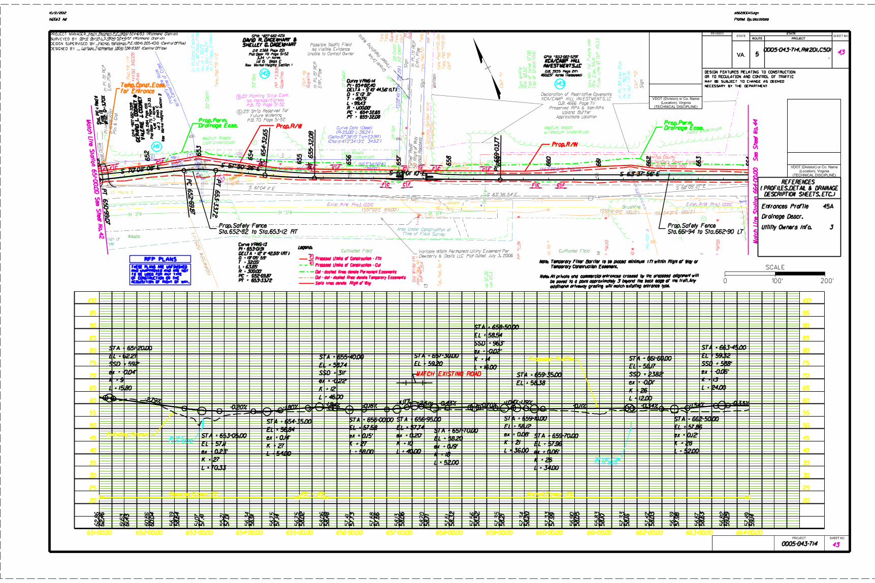
655+00.00 660+00.00651+00.00 652+00.00 653+00.00 654+00.00 656+00.00 657+00.00 658+00.00 659+00.00 661+00.00 662+00.00 663+00.00 664+00.00
20
25
30
35
40
45
50
55
60
65
70
75
80
85
90
95
100
20
25
30
35
40
45
50
55
60
65
70
75
80
85
90
95
100
d86280043.dgn
Plotted By: alex.taloma11:00:13 AM
10/2/2012
d86280043.dgn
Plotted By: alex.taloma11:00:13 AM
10/2/2012
PROJECT MANAGER
SURVEYED BY
DESIGN SUPERVISED BY
DESIGNED BY
VA.
STATE
ROUTE PROJECT
VA.
REVISEDSTATE
STATE
ROUTE PROJECTSHEET NO.
DESIGN FEATURES RELATING TO CONSTRUCTION
OR TO REGULATION AND CONTROL OF TRAFFIC
MAY BE SUBJECT TO CHANGE AS DEEMED
NECESSARY BY THE DEPARTMENT
PROJECT SHEET NO.
(TECHNICAL DISCIPLINE)
(Location), Virginia
VDOT (Division) or Co. Name
(TECHNICAL DISCIPLINE)
(Location), Virginia
VDOT (Division) or Co. Name
5 430005-043-714, RW201, C501
Matc
h Lin
e Statio
n 651+0
0.0
0 See Sheet N
o. 4
2 M
atc
h Lin
e Station 664+0
0.0
0 See Sheet
No. 4
4
Drainage Descr.
Entrances Profile
REFERENCES
( PROFILES, DETAIL & DRAINAGE
DESCRIPTION SHEETS, ETC. )
Kevin Reichert, P.E. (804) 524-6153 (Richmond District)
David Burch, L.S. (804) 524-6157 (Richmond District)
Vernon Heishman, P.E. (804) 225-4310 (Central Office)
Larissa Tachmetova (804) 786-8387 (Central Office)
430005-043-714
45A
THESE PLANS ARE UNFINISHED
AND UNAPPROVED AND ARE NOT
TO BE USED FOR ANY TYPE
OF CONSTRUCTION OR THE
ACQUISITION OF RIGHT OF WAY.
RFP PLANS
Existing Ground
Proposed Profile
Normal Crown -2%2% - -2%:Reverse Crown 2%
Solid lines denote Right of Way
Dot - dot - dashed lines denote Temporary Easements
Dot - dashed lines denote Permanent Easements
C
FProposed Limits of Construction - Fill
Proposed Limits of Construction - Cut
Legend:
Utility Owners Info. 3
Temporary Construction Easement.
Temporary Filter Barrier to be placed minimum 1 ft within Right of Way orNote:
Note:
additional driveway grading will match existing entrance type.
be paved to a point approximately 3’ beyond the back edge of the trail. Any All private and commercial entrances crossed by the proposed alignment will
0 100’ 200’
SCALE
Mailbox
Gra
vel Drive
Tim
ber
Retaining W
alls
Gravel
Drive
Heavy Underb
rush
Mailbox
Entr. Pip
eIn Pl. 15"
RCP
Entr. Pip
e
In Pl. 15"
RCP
Sig
n
Sig
n
Sig
n
Entr. Pip
e
In Pl. 15"
RCP
Asphalt R
oad
way
50’
Rig
ht of
Way
Turner Road
(39.00’)
(N63°34’56"W)
(N63°34’56"W 400.17’)
(S61°14’47"E 532.00’)
(S28°4
5’13"W 291.29’)
(N63°35’21"W 749.29’)
(Chord=N72°34’13"E 34.62’)(Delta=87°38’15" Tan=23.99’)
(R=25.00’ L=38.24’)
Curve Data (Deed)
D.B. 4624 Page 1100
35’ Sanitary Sewer Easement
Henrico County
Approximate Location
Upland Buffer
Preserved RPA & Non-RPA
D.B. 4666 Page 711
KCA/CAMP HILL INVESTMENTS, LC
Declaration of Restrictive Covenants
VDOT Project #1221-C
Existing Right of Way
31.85’
+72.75
RM-16 7
8 A
B
A
B
P.B. 70 Page 51-52 Future Widening
25’ Strip Reserved for
P.B. 70 Page 51-52No Ingress/Egress
20’ Planting Strip Esmt.
PL
PL
PL
Light UnderbrushMedium Woods
Light UnderbrushLight Woods
Poor Condition
4 Strands Barbed Wire
Poor Conditio
n
4 Str
ands Barbed
Wire
w/Medium UnderbrushMedium Woods
20"
Cedar
32"
Oak
21" C
edar
24"
Oak
30"
Cedar
20"
Cedar
Unable to Contact Owner
No Visible Evidence
Possible Septic Field
With Centerline of Creek
Property Line Runs
3"
Oak
Brushline
Cultivated Field Cultivated Field
US Route 5
Inv.
Out
= 57.2
8
Inv. In =
57.3
4
In Pl. 12"
Conc. Pip
e
Woods
Rip-R
ap
Gravel
Gravel
Inv.
Out
= 47.18
Inv. In =
50.15
In Pl. 3
0" Ir
on Pip
e
S 61° 04’ 11" E
S 63° 38’ 54" E
S 68° 05’ 27" E
145
150
155
Z
Dewberry & Davis LLC Plat Dated July 3, 2006Variable Width Permanent Utility Easement Per
PL
Pin
&
Cap
PI 14
5+2
1.52
In Pl. C
onc. End
wall
Inv.
Out
= 49.2
4In
v. In =
50.7
2In Pl. 3
6"
Conc. Pip
eIn Pl. C
onc. End
wall
Time of Field Survey
Area Under Construction at
Time of Field Survey
Area Under Construction at
Exist. R/W Proj. 1221CExist. R/W Proj. 1221C
VD
OT
Dis
k #43-0
543
PI 15
1+30.0
7
VD
OT
Dis
k #43-0
544
PI 15
4+8
3.5
7
PP
LJ54
Guywires
Tele. Ped. #
19 1/
2
Guywires
Guywire
PP #33097
Tele. Ped. N
o. #
Tele.
MH
Tele. Ped. #
20
Tele. Ped. #
21
Tele. Ped. N
o#
Guywire
T
T
T
T
T
T
T
Tele. Ped. #
P10-121
Tele. Ped. #
P10-J
Box
Tele. Ped. #
19 1/
4
PP #K
K50 316
D26
Top of
Gravel 55.6
Top of
Valve 57.0
0Rim 58.5
2San.
MH
FM
Top of
Gravel 56.1
Top of
Valve 58.12
Rim 59.11
San.
MH
FM
FLow
LIn
e 16"
DIP 45.3
3Rim
Ele
v. 55.4
1San.
MH for Future Use
Flo
w
Lin
e 16"
DIP 45.9
0Rim 63.17
San.
MH for Future Use
Top of
Gravel 55.3
Top of
Valve 57.3
6Rim 58.2
9San. F
MV
TT
S
S
S
S
C&
P #8
C&
P #9
Guywires
PP
No. #
PP #25205 2
A
C&
P #10
C&
P #11
C&
P #12
PP #LJ91
PP #
MJ10
PP #72560
PP #
MI5
8
Tel. P
ed.
No #
Tel. P
ed.
No #
Tel. P
ed.
No #
PP #LJ54
Guy
Wires (4)
T
TT
WW4
WW3
DP-W1
WW1
WW2
VA
LE
RIE J.
CO
ON
EY
GE
RA
RD
L.
CO
ON
EY
&
SHELLEY G. DAGENHARTDAVID R. DAGENHART &
INVESTMENTS, LC
KCA/CAMP HILL
Prop. R/W
Prop. R/W
for Entrance
Temp. Const. Ease.
Drainage Ease.Prop. Perm.
Drainage Ease.Prop. Perm.
Sta. 652+82 to Sta. 653+12 RT
Prop. Safety Fence
Sta. 661+94 to Sta. 662+90 LT
Prop. Safety Fence
W=12’ G
=+3.7
0%
Type III
Std. P
E-1 R
eq’d
Curve VRN6-13
PI = 653+01.91
T = 32.05’
L = 63.85’
R = 300.00’
652+69.87PC =
PT = 653+33.72
Curve VRN6-14
PI = 654+82.40
T = 49.75’
L = 99.43’
R = 1,100.00’
654+32.65PC =
PT = 655+32.08
PT 650+9
9.0
7
651 652
PC 652
+69.8
7
653
PT 653
+33.7
2
654
PC 654+3
2.6
5
655
PT 655+3
2.0
8
656
657
658
659
PI 6
59+0
3.7
7
660
661
662
663
664
C F F C
C FF C
C F F C
FC CF
F F C C F
FC CF
C
12BH-
006
12BH-
006
56.02
New
Market
Heig
hts Section 2
Lot 3
Block C
4.4
8 +/-
Acres
Plat
Book 75 Page 33-3
5D.B. 218
4 Page 10
51
GPIN #827-6
82-3
099
New Market Heights Section 1 Lot 15 Block C
3.34 +/- AcresPlat Book 70 Page 51-52
D.B. 2368 Page 221
GPIN #827-682-4251
460.657 Acres (Assessed)
D.B. 3935 Page 2171
GPIN #833-682-5297
141
142
143
36" RCPFL in 50.72
30" Iron PipeFL in 50.15
STA = 651+20.00
EL = 62.27
L = 15.80
K = 9
ex = -0.04’
SSD = 592’
STA = 653+05.00
EL = 57.11
-2.79%
L = 70.33
K = 27
ex = 0.23’
STA = 654+35.00
EL = 56.84
-0.20%
L = 54.00
K = 27
ex = 0.14’
STA = 655+40.00
EL = 58.74
+1.80%-1.94%
L = 46.00
K = 12
ex = -0.22’
SSD = 311’
STA = 656+00.00
EL = 57.58
L = 58.00
K = 27
ex = 0.15’
STA = 656+95.00
EL = 57.74
+0.18%
L = 40.00
K = 10
ex = 0.20’
STA = 657+30.00
EL = 59.20
+4.17%
STA = 657+70.00
EL = 58.20
-2.51%
L = 52.00
K = 18
ex = 0.19’
STA = 658+50.00
EL = 58.54
+0.43% -0.70%
L = 16.00
K = 14
ex = -0.02’
SSD = 963’
STA = 659+10.00
EL = 58.12
L = 36.00
K = 21
ex = 0.08’
STA = 659+35.00
EL = 58.38
+1.04%
STA = 659+70.00
EL = 57.96
-1.19%
L = 34.00
K = 26
ex = 0.06’
STA = 661+60.00
EL = 58.17
+0.11%
L = 12.00
K = 26
ex = -0.01’
SSD = 2382’
STA = 662+50.00
EL = 57.86
-0.34%
L = 52.00
K = 28
ex = 0.12’
STA = 663+45.00
EL = 59.32
+1.54%
L = 24.00
K = 13
ex = -0.06’
SSD = 588’
-0.33%
MATCH EXISTING ROAD
62.8
6
61.63
60.8
6
56.3
9
51.07
55.2
1
56.3
4
56.7
5
56.7
5
58.0
6
57.4
1
57.6
8
58.13
58.7
0
57.6
1
57.5
6
57.3
5
57.3
4
57.3
3
56.9
0
55.8
3
57.3
3
57.4
2
56.3
9
56.6
7
56.8
2
57.4
9
62.4
6
61.43
60.0
4
58.6
4
57.4
1
57.0
1
56.9
1
57.14
58.0
2
58.4
8
57.7
3
57.6
6
58.0
6
58.7
1
58.3
2
58.5
2
58.2
1
58.2
0
57.9
9
58.0
5
58.10
58.16
58.0
3
57.9
8
58.6
3
59.2
9
59.14

CH -
Fat Clay
CL -
Lean Clay
FL -Fill
GC - Clayey
Gravel
GM - Silty
Gravel
GP - Poorly-
graded Gravel
GW - Well-
Graded Gravel
ML - Silt
SC -
Clayey Sand
CL-ML
GC-GM
SW - Well-
Graded Sand
SM - Silty
Sand
SP - Poorly-
Graded Sand
Pavement/Soils
ASPH-
ASPHALT PVT
CONC-
CONCRETE PVT
GP-GC
GP-GM
GW-GC
GW-GM
SP-SC
SP-SM
SW-SC
SW-SM
AND -
Andesite
BST -
Basalt
CAV -
Cavity
DBS -
Diabase
DRT -
Diorite
GBR -
Gabbro
GGE -
Gouge SPT
Core
Grab
No
Recovery
Other
SLS -
Siltstone
SST-SHL -
Interbedded
Sandstone/Shale
MYL -
Mylonite
PHY -
Phyllite
RHY -
Rhyolite
SCH -
Schist
SedimentaryRocks
MetamorphicRocks
SamplingIgneousRocks
MATERIAL AND SAMPLE
SYMBOLS LIST
GNS -
Gneiss
Auger
Undisturbed
CGL -
Conglomorate
COL -
Coal
GWK -
Graywacke
LST -
Limestone
SHL -
Shale
SST -
Sandstone
CLST - Cherty
Limestone
SLT -
Slate
GRD -
Granodiorite
GRN
Granite
POR -
Porphyry
SE -
Shell Bed
UCY -
Underclay
SST-SLS -
Interbedded
Sandstone/Siltstone
MH -
Elastic Silt
MH/CH
MH/ML
MH/SM
ML/CL
ML/GM
ML/SM
GM/GP
GM/ML
GM/SM
HWR
Highly Weathered
Rock
MST
Mudstone
BRC -
Breccia
Misc.
SHDS
Shaly Dolostone
CHK
Chalk
SHLS-Shaly
Limestone
MSH
Silty Shale
Page 1of 2
SSHL
Sandy Shale
Vane
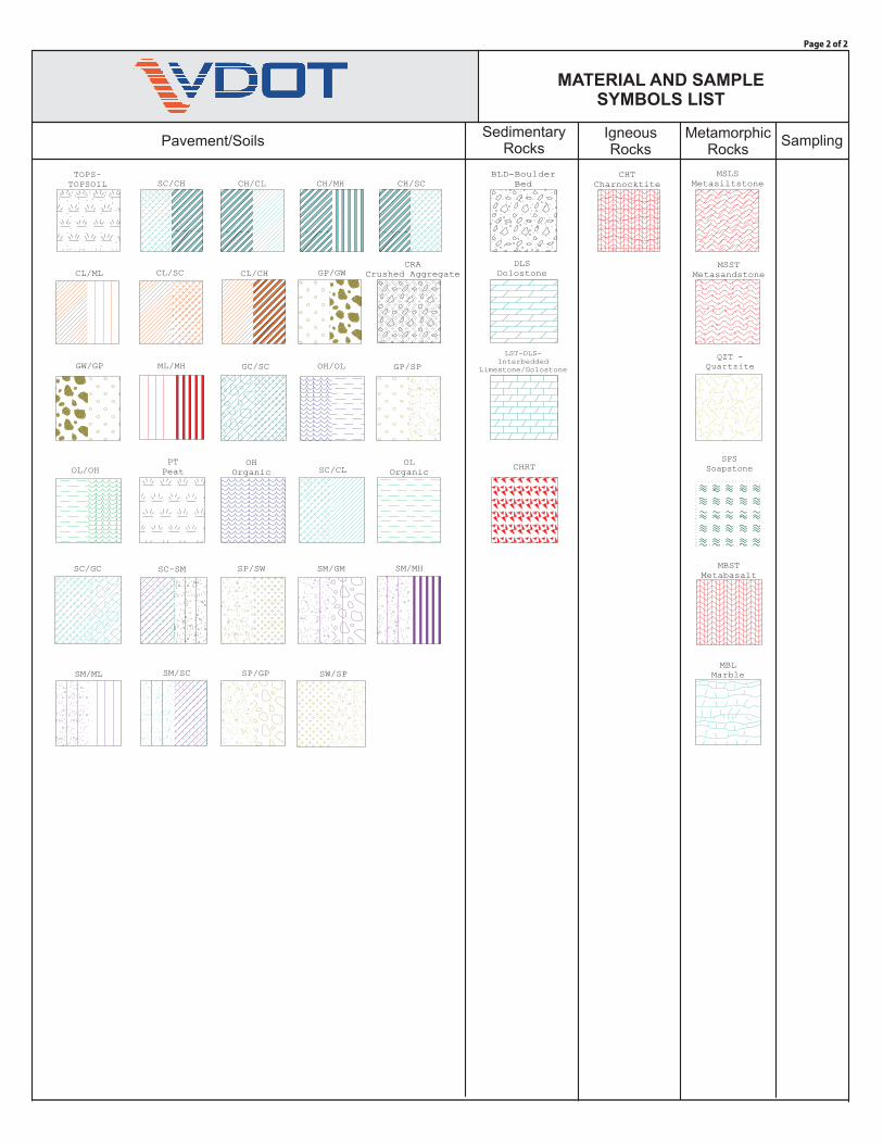
Pavement/SoilsSedimentary
RocksMetamorphic
RocksSampling
IgneousRocks
MATERIAL AND SAMPLE
SYMBOLS LIST
TOPS-
TOPSOIL CH/CL CH/MH CH/SC
CL/ML CL/SC CL/CHCRA
Crushed Aggregate
GC/SC
GP/GW
GP/SPGW/GP ML/MH
OH
Organic
OH/OL
OL
OrganicOL/OHPT
Peat
SC/CH
SC/CL
SC/GC SC-SM
BLD-Boulder
Bed
CHT
Charnocktite
DLS
Dolostone
LST-DLS-
Interbedded
Limestone/Dolostone
MSLS
Metasiltstone
MSST
Metasandstone
QZT -
Quartzite
MBST
Metabasalt
SPS
Soapstone
MBL
Marble
Page 2 of 2
SP/SW SM/GM SM/MH
SM/ML SM/SC SP/GP SW/SP
CHRT

UNIFIED SOIL CLASSIFICATION AND SYMBOL CHART LABORATORY CLASSIFICATION CRITERIA
PLASTICITY CHART
COARSE-GRAINED SOILS
FINE-GRAINED SOILS
(more than 50% of material is larger than No. 200 sieve size.)
(50% or more of material is smaller than No. 200 sieve size.)
Well-graded gravels, gravel-sandmixtures, little or no fines
greater than 4;
greater than 4;
between 1 and 3
between 1 and 3
=
=
=
=
Clean Gravels (Less than 5% fines)
C
C
C
C
D
D
D
D
D
D
D
D
D
D
u
u
c
c
60
60
30
30
x
x
10
10
10
10
60
60
Clean Sands (Less than 5% fines)
Above "A" line with P.I. between4 and 7 are borderline casesrequiring use of dual symbols
Limits plotting in shaded zonewith P.I. between 4 and 7 areborderline cases requiring useof dual symbols.
Determine percentages of sand and gravel from grain-size curve. Dependingon percentage of fines (fraction smaller than No. 200 sieve size),coarse-grained soils are classified as follows:
Less than 5 percentMore than 12 percent5 to 12 percent
GW, GP, SW, SPGM, GC, SM, SC
Borderline cases requiring dual symbols
Gravels with fines (More than 12% fines)
Sands with fines (More than 12% fines)
Well-graded sands, gravelly sands,little or no fines
Silty gravels, gravel-sand-silt mixturesAtterberg limits below "A"line or P.I. less than 4
Atterberg limits below "A"line or P.I. less than 4
Atterberg limits above "A"line with P.I. greater than 7
Atterberg limits above "A"line with P.I. greater than 7
Silty sands, sand-silt mixtures
Inorganic silts and very fine sands, rockflour, silty of clayey fine sands or clayeysilts with slight plasticity
Inorganic clays of low to mediumplasticity, gravelly clays, sandy clays,silty clays, lean clays
Inorganic silts, micaceous ordiatomaceous fine sandy or silty soils,elastic silts
Peat and other highly organic soils
Poorly-graded gravels, gravel-sandmixtures, little or no fines Not meeting all gradation requirements for GW
Not meeting all gradation requirements for GWPoorly graded sands, gravelly sands,little or no fines
Clayey gravels, gravel-sand-claymixtures
Clayey sands, sand-clay mixtures
Inorganic clays of high plasticity, fatclays
Organic silts and organic silty clays oflow plasticity
Organic clays of medium to highplasticity, organic silts
60
50
40
30
20
10
00 10 20 30 40 50
LIQUID LIMIT (LL) (%)
CL
CL+ML
CH
PL
AS
TIC
ITY
IND
EX
(P
I) (
%)
60 70 80 90 100
GW GW
GRAVELS
SANDS
SILTS
AND
CLAYS
SILTS
AND
CLAYS
HIGHLY
ORGANIC
SOILS
More than 50%of coarse
fraction largerthan No. 4sieve size
50% or moreof coarse
fraction smallerthan No. 4sieve size
Liquid limitless than
50%
Liquid limit50%
or greater
SW SW
GM GM
SM SM
ML
MH
PT
GP GP
SPSP
GC GC
SC SC
CL
CH
OL
OH
MH&OH
A LINE:PI = 0.73(LL-20)
ML&OL
UNIFIED SOIL
CLASSIFICATION SYSTEM

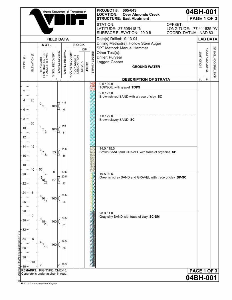
4.5
6
9.5
11
14.5
16
19.5
20.5
22
24.5
26
29.5
31
34.5
36
39.5
0.0 / 29.0TOPSOIL with gravel TOPS
2.0 / 27.0Brownish-red SAND with a trace of clay SC
7.0 / 22.0Brown clayey SAND SC
14.0 / 15.0Brown SAND and GRAVEL with trace of organics SP
19.5 / 9.5Greenish-gray SAND and GRAVEL with trace of clay SP-SC
28.0 / 1.0Gray silty SAND with trace of clay SC-SM
100
100
53
0
67
100
100
100
2 2
1
1 2
3
3 7
8
50 -
-19
18 22
6 10
14
9 15
23
4 7
13
7
DESCRIPTION OF STRATA
RIG TYPE: CME-45.Concrete is under asphalt in road.
GROUND WATER
REMARKS:
PAGE 1 OF 304BH-001
04BH-001PAGE 1 OF 3
OFFSET:LONGITUDE: -77.411835 °WCOORD. DATUM: NAD 83
2012, Commonwealth of Virginia
SP
T_L
OG
:00
5-04
3.G
PJ:
8.3
0.0
02:0
815
05:6
/15/
12
SA
MP
LE IN
TE
RV
AL
2
4
6
8
10
12
14
16
18
20
22
24
26
28
30
32
34
36
38
40
25
20
15
10
5
0
-5
-10
ST
RA
TA
S O I L
% C
OR
E R
EC
OV
ER
Y
R O C K
005-043Over Almonds CreekEast Abutment
DE
PT
H (
ft)
ELE
VA
TIO
N (
ft)
PROJECT #:LOCATION:STRUCTURE:
ST
RA
TA
LE
GE
ND
RO
CK
QU
ALI
TY
DE
SIG
NA
TIO
N
FIELD DATA
DIP
ST
AN
DA
RD
PE
NE
TR
AT
ION
TE
ST
HA
MM
ER
BLO
WS
JOIN
TS
Date(s) Drilled: 9-13-04Drilling Method(s): Hollow Stem AugerSPT Method: Manual HammerOther Test(s):Driller: PuryearLogger: Conner
% S
OIL
RE
CO
VE
RY
SA
MP
LE L
EG
EN
D
STATION:LATITUDE: 37.506418 °NSURFACE ELEVATION: 29.0 ft
LIQ
UID
LIM
IT
LL
MO
IST
UR
E C
ON
TE
NT
(%
)
PLA
ST
ICIT
Y IN
DE
X
LAB DATA
PI

41
44.5
46
49.5
50.5
54.5
56
59.5
61
64.5
66
69.5
70.6
74.5
76
79.5
50.0 / -21.0Greenish gray clayey SAND with gravel SC
53.0 / -24.0Greenish gray clayey SILT with gravel MH
58.0 / -29.0Greenish gray silty CLAY with trace of sand and mica CL-ML
63.0 / -34.0Gray micaceous sandy SILT ML
69.0 / -40.0Greenish gray clayey SAND and GRAVEL with trace of finemica and rock fragments GP-GC
74.0 / -45.0Varigated micaceous sandy SILT with trace of clay ML
77.0 / -48.0Greenish gray silty SAND with trace of mica SM
100
100
100
100
100
100
91
100
12 16
2 5
14
11 50
-
3 12
16
9 10
20
7 14
20
40 40
10
16 20
30
21
DESCRIPTION OF STRATA
RIG TYPE: CME-45.Concrete is under asphalt in road.
GROUND WATER
REMARKS:
PAGE 2 OF 304BH-001
04BH-001PAGE 2 OF 3
OFFSET:LONGITUDE: -77.411835 °WCOORD. DATUM: NAD 83
2012, Commonwealth of Virginia
SP
T_L
OG
:00
5-04
3.G
PJ:
8.3
0.0
02:0
815
05:6
/15/
12
SA
MP
LE IN
TE
RV
AL
42
44
46
48
50
52
54
56
58
60
62
64
66
68
70
72
74
76
78
80
-15
-20
-25
-30
-35
-40
-45
-50
ST
RA
TA
S O I L
% C
OR
E R
EC
OV
ER
Y
R O C K
005-043Over Almonds CreekEast Abutment
DE
PT
H (
ft)
ELE
VA
TIO
N (
ft)
PROJECT #:LOCATION:STRUCTURE:
ST
RA
TA
LE
GE
ND
RO
CK
QU
ALI
TY
DE
SIG
NA
TIO
N
FIELD DATA
DIP
ST
AN
DA
RD
PE
NE
TR
AT
ION
TE
ST
HA
MM
ER
BLO
WS
JOIN
TS
Date(s) Drilled: 9-13-04Drilling Method(s): Hollow Stem AugerSPT Method: Manual HammerOther Test(s):Driller: PuryearLogger: Conner
% S
OIL
RE
CO
VE
RY
SA
MP
LE L
EG
EN
D
STATION:LATITUDE: 37.506418 °NSURFACE ELEVATION: 29.0 ft
LIQ
UID
LIM
IT
LL
MO
IST
UR
E C
ON
TE
NT
(%
)
PLA
ST
ICIT
Y IN
DE
X
LAB DATA
PI

80.480.4 / -51.4Borehole Terminated
56 50 -
DESCRIPTION OF STRATA
RIG TYPE: CME-45.Concrete is under asphalt in road.
GROUND WATER
REMARKS:
PAGE 3 OF 304BH-001
04BH-001PAGE 3 OF 3
OFFSET:LONGITUDE: -77.411835 °WCOORD. DATUM: NAD 83
2012, Commonwealth of Virginia
SP
T_L
OG
:00
5-04
3.G
PJ:
8.3
0.0
02:0
815
05:6
/15/
12
SA
MP
LE IN
TE
RV
AL
ST
RA
TA
S O I L
% C
OR
E R
EC
OV
ER
Y
R O C K
005-043Over Almonds CreekEast Abutment
DE
PT
H (
ft)
ELE
VA
TIO
N (
ft)
PROJECT #:LOCATION:STRUCTURE:
ST
RA
TA
LE
GE
ND
RO
CK
QU
ALI
TY
DE
SIG
NA
TIO
N
FIELD DATA
DIP
ST
AN
DA
RD
PE
NE
TR
AT
ION
TE
ST
HA
MM
ER
BLO
WS
JOIN
TS
Date(s) Drilled: 9-13-04Drilling Method(s): Hollow Stem AugerSPT Method: Manual HammerOther Test(s):Driller: PuryearLogger: Conner
% S
OIL
RE
CO
VE
RY
SA
MP
LE L
EG
EN
D
STATION:LATITUDE: 37.506418 °NSURFACE ELEVATION: 29.0 ft
LIQ
UID
LIM
IT
LL
MO
IST
UR
E C
ON
TE
NT
(%
)
PLA
ST
ICIT
Y IN
DE
X
LAB DATA
PI

4.5
6
9.5
11
14.5
16
19.5
20.5
22
24.5
26
29.5
31
34.5
36
39.5
0.0 / 26.6Sand and gravel with coal-like material (possible abandonedRR bed - Fill). FL
13.0 / 13.6Gray silty CLAY CL-ML
19.0 / 7.6Large GRAVEL layer GP19.5 / 7.1Brown coarse SAND and GRAVEL with a trace of clay SP-SC
23.0 / 3.6Gray coarse SAND and GRAVEL SP
27.0 / -0.4Gray fine to coarse SAND with trace of silt SW-SM
33
67
100
0
67
100
100
100
3 1
2
2 1
2
1 2
2
50 -
-7
15 22
9 21
20
6 8
15
3 7
11
7
DESCRIPTION OF STRATA
RIG TYPE: CME-45.Terminated hole because of rain. Drilling pressure was 500 to 900 lbs. last 12 ft. (Hard Drilling).
GROUND WATER
REMARKS:
PAGE 1 OF 204BH-002
04BH-002PAGE 1 OF 2
OFFSET:LONGITUDE: -77.412104 °WCOORD. DATUM: NAD 83
2012, Commonwealth of Virginia
SP
T_L
OG
:00
5-04
3.G
PJ:
8.3
0.0
02:0
815
05:6
/15/
12
SA
MP
LE IN
TE
RV
AL
2
4
6
8
10
12
14
16
18
20
22
24
26
28
30
32
34
36
38
40
25
20
15
10
5
0
-5
-10
ST
RA
TA
S O I L
% C
OR
E R
EC
OV
ER
Y
R O C K
005-043Over Almonds CreekWest Abutment
DE
PT
H (
ft)
ELE
VA
TIO
N (
ft)
PROJECT #:LOCATION:STRUCTURE:
ST
RA
TA
LE
GE
ND
RO
CK
QU
ALI
TY
DE
SIG
NA
TIO
N
FIELD DATA
DIP
ST
AN
DA
RD
PE
NE
TR
AT
ION
TE
ST
HA
MM
ER
BLO
WS
JOIN
TS
Date(s) Drilled: 9-27-04Drilling Method(s): Hollow Stem AugerSPT Method: Manual HammerOther Test(s):Driller: PuryearLogger: Conner
% S
OIL
RE
CO
VE
RY
FIRST ENCOUNTERED AT: 9.2 ft DEPTH
SA
MP
LE L
EG
EN
D
STATION:LATITUDE: 37.506626 °NSURFACE ELEVATION: 26.6 ft
LIQ
UID
LIM
IT
LL
MO
IST
UR
E C
ON
TE
NT
(%
)
PLA
ST
ICIT
Y IN
DE
X
LAB DATA
PI

41
44.5
45.6
49.5
51
54.5
56
44.0 / -17.4Greenish gray clayey SAND SC
48.0 / -21.4Greenish gray clayey SILT with trace of sand and rockfragments MH
56.0 / -29.4Borehole terminated
100
100
100
100
14 14
17 38
12
14 20
30
12 18
23
DESCRIPTION OF STRATA
RIG TYPE: CME-45.Terminated hole because of rain. Drilling pressure was 500 to 900 lbs. last 12 ft. (Hard Drilling).
GROUND WATER
REMARKS:
PAGE 2 OF 204BH-002
04BH-002PAGE 2 OF 2
OFFSET:LONGITUDE: -77.412104 °WCOORD. DATUM: NAD 83
2012, Commonwealth of Virginia
SP
T_L
OG
:00
5-04
3.G
PJ:
8.3
0.0
02:0
815
05:6
/15/
12
SA
MP
LE IN
TE
RV
AL
42
44
46
48
50
52
54
56
-15
-20
-25
ST
RA
TA
S O I L
% C
OR
E R
EC
OV
ER
Y
R O C K
005-043Over Almonds CreekWest Abutment
DE
PT
H (
ft)
ELE
VA
TIO
N (
ft)
PROJECT #:LOCATION:STRUCTURE:
ST
RA
TA
LE
GE
ND
RO
CK
QU
ALI
TY
DE
SIG
NA
TIO
N
FIELD DATA
DIP
ST
AN
DA
RD
PE
NE
TR
AT
ION
TE
ST
HA
MM
ER
BLO
WS
JOIN
TS
Date(s) Drilled: 9-27-04Drilling Method(s): Hollow Stem AugerSPT Method: Manual HammerOther Test(s):Driller: PuryearLogger: Conner
% S
OIL
RE
CO
VE
RY
FIRST ENCOUNTERED AT: 9.2 ft DEPTH
SA
MP
LE L
EG
EN
D
STATION:LATITUDE: 37.506626 °NSURFACE ELEVATION: 26.6 ft
LIQ
UID
LIM
IT
LL
MO
IST
UR
E C
ON
TE
NT
(%
)
PLA
ST
ICIT
Y IN
DE
X
LAB DATA
PI

0.0 / 50.06Brown silty CLAY CH
2.0 / 48.06Brown silty SAND SM
4.0 / 46.06Brown SAND with gravel SP
8.0 / 42.06Grey clayey SAND SC
10.0 / 40.06Grey sandy SILT ML
25.5 / 24.56Borehole Terminated
100
100
100
100
100
100
100
100
PAGE 1 OF 1
12BH-003
12BH-003
FIELD DESCRIPTION OF STRATA
GROUND WATER
PAGE 1 OF 1OFFSET:LONGITUDE: -77.325852° WCOORD. DATUM: NAD 83
REMARKS: Rig Type: Mudbug.
Copyright 2012, Commonwealth of Virginia
SP
T_L
OG
:00
05-0
43-7
14.G
PJ:
8.30
.002
:092
710:
6/1
4/12
LAB DATA
MO
IST
UR
E C
ON
TE
NT
(%
)
PLA
ST
ICIT
Y IN
DE
X
PILL
LIQ
UID
LIM
IT
SO
IL R
EC
OV
ER
Y (
%)
CO
RE
RE
CO
VE
RY
(%
)FIRST ENCOUNTERED AT 5.3 ft DEPTH
NO LONG TERM MEASUREMENTS TAKEN
DIP °
R O C K
SA
MP
LE L
EG
EN
D
S O I L
PROJECT #:LOCATION:STRUCTURE:
ELE
VA
TIO
N (
ft)
45
40
35
30
25
DE
PT
H (
ft)
SA
MP
LE IN
TE
RV
AL
RO
CK
QU
ALI
TY
DE
SIG
NA
TIO
N
ST
AN
DA
RD
PE
NE
TR
AT
ION
TE
ST
HA
MM
ER
BLO
WS
FIELD DATA
ST
RA
TA
LE
GE
ND
JOIN
TS
ST
RA
TA
2
4
6
8
10
12
14
16
18
20
22
24
STATION:LATITUDE: 37.432852° NSURFACE ELEVATION: 50.06 ft
0005-043-714Henrico CountyBOX CULVERT
Date(s) Drilled: 2-9-12 - 2-9-12Drilling Method(s): Hollow Stem AugerSPT Method: Automatic HammerOther Test(s):Driller: PuryearLogger: Lewis
wh
8
2
wh
wh
3
wh
wh
4
wh
4
4
3
9
wh
7
7
1
3
wh
5
4
1
4
3
6
1
3
5
2
4
6
8
10
14
15.5
19
20.5
24
25.5
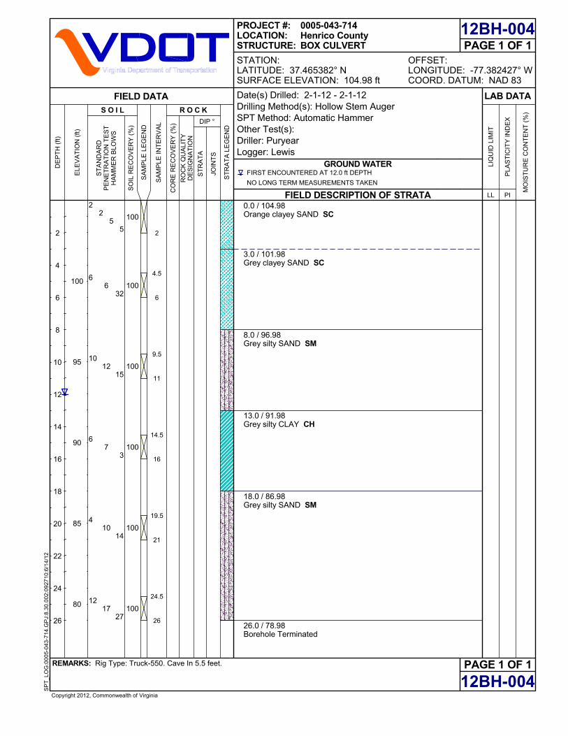
0.0 / 104.98Orange clayey SAND SC
3.0 / 101.98Grey clayey SAND SC
8.0 / 96.98Grey silty SAND SM
13.0 / 91.98Grey silty CLAY CH
18.0 / 86.98Grey silty SAND SM
26.0 / 78.98Borehole Terminated
100
100
100
100
100
100
PAGE 1 OF 1
12BH-004
12BH-004
FIELD DESCRIPTION OF STRATA
GROUND WATER
PAGE 1 OF 1OFFSET:LONGITUDE: -77.382427° WCOORD. DATUM: NAD 83
REMARKS: Rig Type: Truck-550. Cave In 5.5 feet.
Copyright 2012, Commonwealth of Virginia
SP
T_L
OG
:00
05-0
43-7
14.G
PJ:
8.30
.002
:092
710:
6/1
4/12
LAB DATA
MO
IST
UR
E C
ON
TE
NT
(%
)
PLA
ST
ICIT
Y IN
DE
X
PILL
LIQ
UID
LIM
IT
SO
IL R
EC
OV
ER
Y (
%)
CO
RE
RE
CO
VE
RY
(%
)FIRST ENCOUNTERED AT 12.0 ft DEPTH
NO LONG TERM MEASUREMENTS TAKEN
DIP °
R O C K
SA
MP
LE L
EG
EN
D
S O I L
PROJECT #:LOCATION:STRUCTURE:
ELE
VA
TIO
N (
ft)
100
95
90
85
80
DE
PT
H (
ft)
SA
MP
LE IN
TE
RV
AL
RO
CK
QU
ALI
TY
DE
SIG
NA
TIO
N
ST
AN
DA
RD
PE
NE
TR
AT
ION
TE
ST
HA
MM
ER
BLO
WS
FIELD DATA
ST
RA
TA
LE
GE
ND
JOIN
TS
ST
RA
TA
2
4
6
8
10
12
14
16
18
20
22
24
26
STATION:LATITUDE: 37.465382° NSURFACE ELEVATION: 104.98 ft
0005-043-714Henrico CountyBOX CULVERT
Date(s) Drilled: 2-1-12 - 2-1-12Drilling Method(s): Hollow Stem AugerSPT Method: Automatic HammerOther Test(s):Driller: PuryearLogger: Lewis
2
6
10
6
4
12
6
12
7
10
17
32
15
3
14
27
25
52
4.5
6
9.5
11
14.5
16
19.5
21
24.5
26

0.0 / 54.97Brown sandy CLAY CL
4.0 / 50.97Brown silty sand with gravel SM
9.0 / 45.97Orange sandy CLAY CL
11.5 / 43.47Borehole Terminated
100
100
100
PAGE 1 OF 1
12BH-006
12BH-006
FIELD DESCRIPTION OF STRATA
GROUND WATER
PAGE 1 OF 1OFFSET:LONGITUDE: -77.314375° WCOORD. DATUM: NAD 83
REMARKS: Rig Type: Truck-550. Cave In 1.5 feet.
Copyright 2012, Commonwealth of Virginia
SP
T_L
OG
:00
05-0
43-7
14.G
PJ:
8.30
.002
:092
710:
6/1
4/12
LAB DATA
MO
IST
UR
E C
ON
TE
NT
(%
)
PLA
ST
ICIT
Y IN
DE
X
PILL
LIQ
UID
LIM
IT
SO
IL R
EC
OV
ER
Y (
%)
CO
RE
RE
CO
VE
RY
(%
)NOT ENCOUNTERED DURING DRILLING
NO LONG TERM MEASUREMENTS TAKEN
DIP °
R O C K
SA
MP
LE L
EG
EN
D
S O I L
PROJECT #:LOCATION:STRUCTURE:
ELE
VA
TIO
N (
ft)
50
45
DE
PT
H (
ft)
SA
MP
LE IN
TE
RV
AL
RO
CK
QU
ALI
TY
DE
SIG
NA
TIO
N
ST
AN
DA
RD
PE
NE
TR
AT
ION
TE
ST
HA
MM
ER
BLO
WS
FIELD DATA
ST
RA
TA
LE
GE
ND
JOIN
TS
ST
RA
TA
2
4
6
8
10
STATION:LATITUDE: 37.430387° NSURFACE ELEVATION: 54.97 ft
0005-043-714Henrico CountyPIPE
Date(s) Drilled: 2-1-12 - 2-1-12Drilling Method(s): Hollow Stem AugerSPT Method: Automatic HammerOther Test(s):Driller: PuryearLogger: Lewis
1
8
2
20
4
21
5
wh
1
22
5
6.5
10
11.5
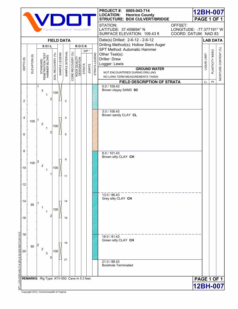
0.0 / 109.43Brown clayey SAND SC
3.0 / 106.43Brown sandy CLAY CL
8.0 / 101.43Brown silty CLAY CH
13.0 / 96.43Grey silty CLAY CH
18.0 / 91.43Green silty CLAY CH
21.0 / 88.43Borehole Terminated
100
100
100
100
100
PAGE 1 OF 1
12BH-007
12BH-007
FIELD DESCRIPTION OF STRATA
GROUND WATER
PAGE 1 OF 1OFFSET:LONGITUDE: -77.377191° WCOORD. DATUM: NAD 83
REMARKS: Rig Type: ATV-550. Cave In 5.3 feet.
Copyright 2012, Commonwealth of Virginia
SP
T_L
OG
:00
05-0
43-7
14.G
PJ:
8.30
.002
:092
710:
6/1
4/12
LAB DATA
MO
IST
UR
E C
ON
TE
NT
(%
)
PLA
ST
ICIT
Y IN
DE
X
PILL
LIQ
UID
LIM
IT
SO
IL R
EC
OV
ER
Y (
%)
CO
RE
RE
CO
VE
RY
(%
)NOT ENCOUNTERED DURING DRILLING
NO LONG TERM MEASUREMENTS TAKEN
DIP °
R O C K
SA
MP
LE L
EG
EN
D
S O I L
PROJECT #:LOCATION:STRUCTURE:
ELE
VA
TIO
N (
ft)
105
100
95
90
DE
PT
H (
ft)
SA
MP
LE IN
TE
RV
AL
RO
CK
QU
ALI
TY
DE
SIG
NA
TIO
N
ST
AN
DA
RD
PE
NE
TR
AT
ION
TE
ST
HA
MM
ER
BLO
WS
FIELD DATA
ST
RA
TA
LE
GE
ND
JOIN
TS
ST
RA
TA
2
4
6
8
10
12
14
16
18
20
STATION:LATITUDE: 37.459694° NSURFACE ELEVATION: 109.43 ft
0005-043-714Henrico CountyBOX CULVERT/BRIDGE
Date(s) Drilled: 2-6-12 - 2-6-12Drilling Method(s): Hollow Stem AugerSPT Method: Automatic HammerOther Test(s):Driller: DrewLogger: Lewis
1
1
3
1
2
3
2
2
1
2
1
1
1
1
3
2
2
1
2
5
2
4
6
9
11
14
16
19
21
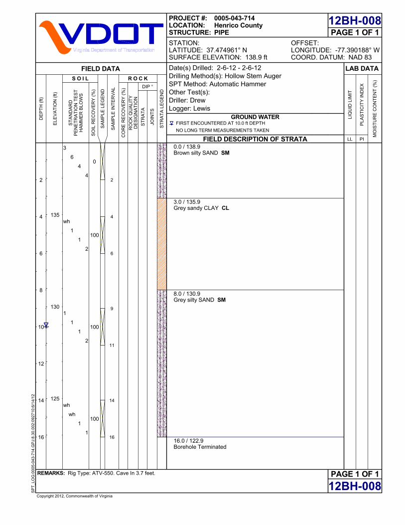
0.0 / 138.9Brown silty SAND SM
3.0 / 135.9Grey sandy CLAY CL
8.0 / 130.9Grey silty SAND SM
16.0 / 122.9Borehole Terminated
0
100
100
100
PAGE 1 OF 1
12BH-008
12BH-008
FIELD DESCRIPTION OF STRATA
GROUND WATER
PAGE 1 OF 1OFFSET:LONGITUDE: -77.390188° WCOORD. DATUM: NAD 83
REMARKS: Rig Type: ATV-550. Cave In 3.7 feet.
Copyright 2012, Commonwealth of Virginia
SP
T_L
OG
:00
05-0
43-7
14.G
PJ:
8.30
.002
:092
710:
6/1
4/12
LAB DATA
MO
IST
UR
E C
ON
TE
NT
(%
)
PLA
ST
ICIT
Y IN
DE
X
PILL
LIQ
UID
LIM
IT
SO
IL R
EC
OV
ER
Y (
%)
CO
RE
RE
CO
VE
RY
(%
)FIRST ENCOUNTERED AT 10.0 ft DEPTH
NO LONG TERM MEASUREMENTS TAKEN
DIP °
R O C K
SA
MP
LE L
EG
EN
D
S O I L
PROJECT #:LOCATION:STRUCTURE:
ELE
VA
TIO
N (
ft)
135
130
125
DE
PT
H (
ft)
SA
MP
LE IN
TE
RV
AL
RO
CK
QU
ALI
TY
DE
SIG
NA
TIO
N
ST
AN
DA
RD
PE
NE
TR
AT
ION
TE
ST
HA
MM
ER
BLO
WS
FIELD DATA
ST
RA
TA
LE
GE
ND
JOIN
TS
ST
RA
TA
2
4
6
8
10
12
14
16
STATION:LATITUDE: 37.474961° NSURFACE ELEVATION: 138.9 ft
0005-043-714Henrico CountyPIPE
Date(s) Drilled: 2-6-12 - 2-6-12Drilling Method(s): Hollow Stem AugerSPT Method: Automatic HammerOther Test(s):Driller: DrewLogger: Lewis
3
wh
1
wh
6
1
1
wh
4
1
1
1
4
2
2
1
2
4
6
9
11
14
16