calumet montana refining company, llc
TRANSCRIPT
Greg Gianforte, Governor I Chris Dorrington, Director I P.O. Box 200901 I Helena, MT 59620-0901 I (406) 444-2544 I www.deq.mt.gov
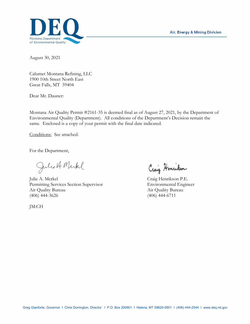
August 30, 2021 Calumet Montana Refining, LLC 1900 10th Street North East Great Falls, MT 59404 Dear Mr. Dauner: Montana Air Quality Permit #2161-35 is deemed final as of August 27, 2021, by the Department of Environmental Quality (Department). All conditions of the Department’s Decision remain the same. Enclosed is a copy of your permit with the final date indicated. Conditions: See attached. For the Department,
Julie A. Merkel Craig Henrikson P.E. Permitting Services Section Supervisor Environmental Engineer Air Quality Bureau Air Quality Bureau (406) 444-3626 (406) 444-6711 JM:CH
Montana Department of Environmental Quality Air, Energy & Mining Division
Montana Air Quality Permit #2161-35
Calumet Montana Refining 1900 10th Street North East
Great Falls, MT 59404
August 27, 2021
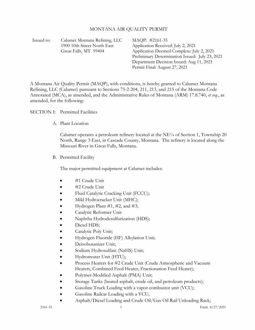
2161-35 1 Final: 8/27/2021
MONTANA AIR QUALITY PERMIT
Issued to: Calumet Montana Refining, LLC
1900 10th Street North East Great Falls, MT 59404
MAQP: #2161-35 Application Received: July 2, 2021 Application Deemed Complete: July 2, 2021 Preliminary Determination Issued: July 23, 2021 Department Decision Issued: Aug 11, 2021 Permit Final: August 27, 2021
A Montana Air Quality Permit (MAQP), with conditions, is hereby granted to Calumet Montana Refining, LLC (Calumet) pursuant to Sections 75-2-204, 211, 213, and 215 of the Montana Code Annotated (MCA), as amended, and the Administrative Rules of Montana (ARM) 17.8.740, et seq., as amended, for the following: SECTION I: Permitted Facilities
A. Plant Location
Calumet operates a petroleum refinery located at the NE¼ of Section 1, Township 20 North, Range 3 East, in Cascade County, Montana. The refinery is located along the Missouri River in Great Falls, Montana.
B. Permitted Facility
The major permitted equipment at Calumet includes:
• #1 Crude Unit • #2 Crude Unit • Fluid Catalytic Cracking Unit (FCCU); • Mild Hydrocracker Unit (MHC); • Hydrogen Plant #1, #2, and #3; • Catalytic Reformer Unit • Naphtha Hydrodesulfurization (HDS); • Diesel HDS; • Catalytic Poly Unit; • Hydrogen Fluoride (HF) Alkylation Unit; • Deisobutanizer Unit; • Sodium Hydrosulfate (NaHS) Unit; • Hydrotreater Unit (HTU); • Process Heaters for #2 Crude Unit (Crude Atmospheric and Vacuum
Heaters, Combined Feed Heater, Fractionation Feed Heater); • Polymer-Modified Asphalt (PMA) Unit; • Storage Tanks (heated asphalt, crude oil, and petroleum products); • Gasoline Truck Loading with a vapor combustor unit (VCU); • Gasoline Railcar Loading with a VCU; • Asphalt/Diesel Loading and Crude Oil/Gas Oil Rail Unloading Rack;

2161-35 2 Final: 8/27/2021
• Primary Flare #1 and Secondary Flare #2; • Miscellaneous Tanks; Utilities (Boilers (#1, #2 and #3), North and South
Cooling Towers, Wastewater Treatment including new Dissolved Air Flotation Unit);
• Sour Water Stripper Ammonia Combustor • Catalytic Thermal Oxidizer for Remediation Project
A complete list of permitted equipment for Calumet is contained in Section I.A. of the permit analysis.
C. Current Permit Action
On July 2, 2021, the Department of Environmental Quality – Air Quality Bureau (Department) received from Calumet an application to modify the MAQP for installation of new equipment and tanks related to the polymer modified asphalt (PMA) production process. This project is titled the Asphalt Upgrades Project. The Asphalt Upgrades Project will provide the refinery with improved PMA production capabilities, more advanced asphalt product blending capabilities, and modernized heating systems for PMA process equipment, PMA storage tanks, and asphalt storage tanks. The project also includes the shutdown of numerous heaters which will be replaced with heaters fired by refinery fuel gas. New equipment included with this permit action is the following:
• Hot Oil Heater (H-1903) • Hot Oil Expansion Tank (D-1906) • Hot Oil Heater (H-1904) • Hot Oil Expansion Tank (D-1908) • Wetting Tank (D-1901) • Crosslinking Tank (D-1907) • Piping Fugitive Components • Tank #55 • Tank #130 • Tank #132 • Tank #133 • PMA Unit Polymer Handling Operations • PMA Unit Prilled Sulfur Handling Operations • Wastewater Components
Tanks #55, #130, #132, and #133 are new tanks maintaining the same tank numbers as those being replaced. Equipment removed from service with this permit action would be the following:
• Heater H-0601 • Tank #55 Heater • Tank #130 Heater • Tank #132 Heater • Tank #133 Heater • Tank #135 Heater

2161-35 3 Final: 8/27/2021
• Tank #137 Heater • Tank #138 Heater • Tank #139 Heater
The following existing operations/tanks may see an increase in throughput related to the Asphalt Upgrades Project but are not currently bottle-necked :
• Asphalt Loading • Tank #135 • Tank #137 • Tank #138 • Tank #139
SECTION II: Limitations and Conditions
A. General Facility Conditions
1. Calumet shall comply with all applicable requirements of ARM 17.8.340, which references 40 Code of Federal Regulations (CFR) Part 60, Standards of Performance for New Stationary Sources (NSPS):
a. Subpart A – General Provisions shall apply to all equipment or
facilities subject to an NSPS Subpart as listed below. b. Subpart Dc – Standards of Performance for Small Industrial–
Commercial Institutional Steam Generating Units for which construction, modification, or reconstruction is commenced after June 9, 1989. This Subpart applies to Boiler #3 and oil heaters H-1903 and H-1904.
c. Subpart J – Standards of Performance for Petroleum Refineries
applies to all fuel gas combustion devices with the exception of those subject to 40 CFR 60, Subpart Ja.
1. FCCU regenerator: for carbon monoxide (CO) and sulfur
dioxide (SO2) (pursuant to Calumet’s Consent Decree (Consent Decree)).
2. Heaters and boilers (Consent Decree).
d. Subpart Ja – Standards of Performance for Petroleum Refineries for
Which Construction, Reconstruction or Modification commenced after May 14, 2007 (H-2101, H-2102, H-4101, H-4102, H-31A, H-31B, Boiler #3, flare system, fuel gas treatment unit (FGT), sour water stripper (SWS), and oil heaters H-1903 and H-1904).
e. Subpart Kb – Standards of Performance for Volatile Organic Liquid Storage Vessels shall apply to all volatile organic storage vessels (including petroleum liquid storage vessels) for which construction, reconstruction or modification commenced after July 23, 1984.

2161-35 4 Final: 8/27/2021
f. Subpart UU – Standards of Performance for Asphalt Processing and Asphalt Roofing Manufacture shall apply to all asphalt storage tanks that processes and stores only non-roofing asphalts, and was constructed or modified since May 26, 1981. Following replacement as part of the Asphalt Upgrades Project, Tank #55 will be subject to the opacity requirements under Subpart UU.
g. Subpart VV – Standards of Performance for Equipment Leaks of Volatile Organic Compounds (VOC) in the Synthetic Organic Chemicals Manufacturing Industry, shall apply to this refinery as required by 40 CFR 60, Subpart GGG and 40 CFR 63, Subpart CC.
h. Subpart VVa – Standards of Performance for Equipment Leaks of VOC in Petroleum Refineries for Which Construction, Reconstruction, or Modification Commenced After November 7, 2006.
i. Subpart GGG – Standards of Performance for Equipment Leaks of VOC in Petroleum Refineries shall apply to the NaHS Unit, Diesel/Gas Oil HDS Unit, Hydrogen Plant, and any other equipment as appropriate. A monitoring and maintenance program as described under 40 CFR 60, Subpart VV shall be instituted.
j. Subpart GGGa - Standards of Performance for Equipment Leaks of VOC in Petroleum Refineries for which Construction, Reconstruction, or Modification Commenced After November 7, 2006. Unless Calumet demonstrates exemption from this standard, the standard applies to compressors, valves, pumps, pressure relief devices, sampling connection system, open-ended valves and lines, flanges, and connectors that are part of the Low Sulfur Fuels expansion project. The piping components within the PMA Unit will be subject to Subpart GGGa following the Asphalt Upgrades Project.
k. Subpart QQQ – Standards of Performance for VOC Emissions from Petroleum Refining Wastewater Systems shall apply to the wastewater treatment system, individual drains, oil-water separators, HTU, Hydrogen Unit, and any other applicable equipment constructed, modified or reconstructed after May 4, 1987.
2. Calumet shall comply with all applicable requirements of ARM 17.8.341, as
specified by 40 CFR Part 61, National Emissions Standards for Hazardous Air Pollutants:
a. Subpart A – General Provisions applies to all equipment or facilities
subject to a NESHAP subpart as listed below: b. Subpart FF – National Emission Standard for Benzene Waste
Operations.
2161-35 5 Final: 8/27/2021
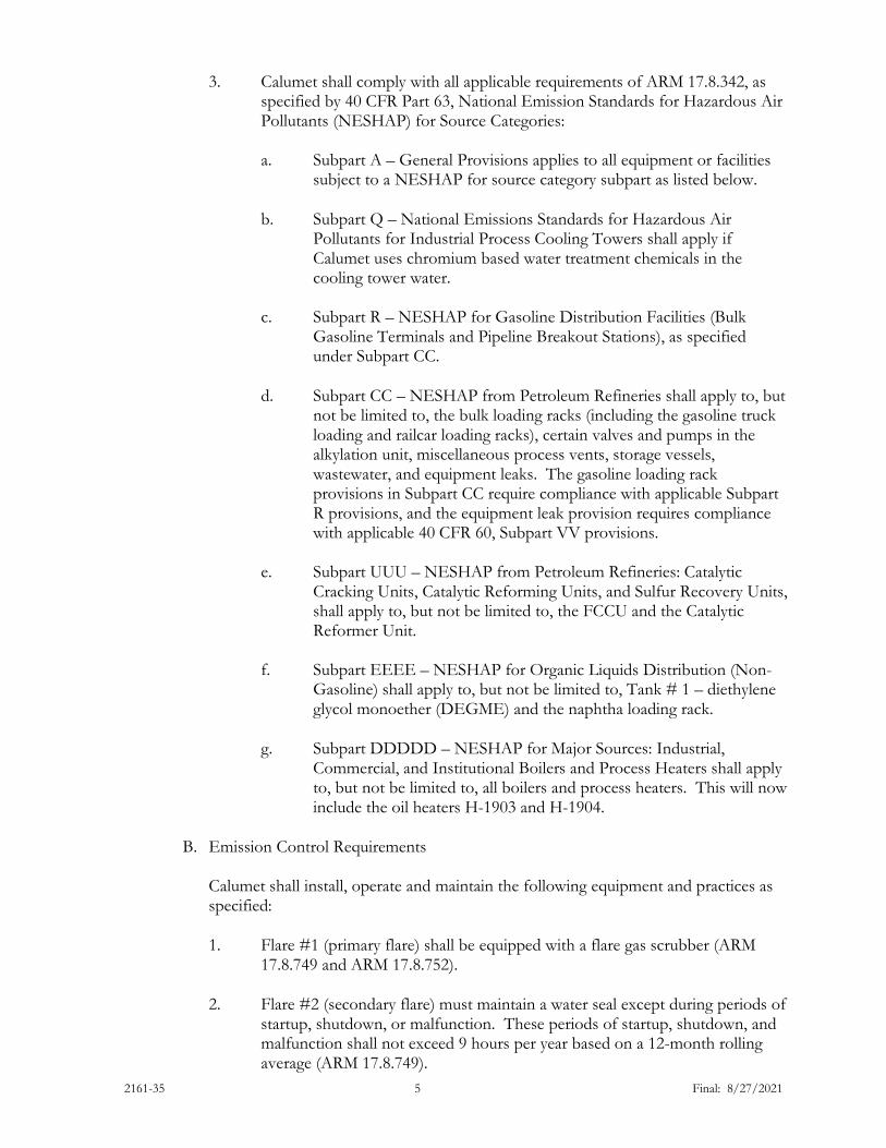
3. Calumet shall comply with all applicable requirements of ARM 17.8.342, as specified by 40 CFR Part 63, National Emission Standards for Hazardous Air Pollutants (NESHAP) for Source Categories:
a. Subpart A – General Provisions applies to all equipment or facilities
subject to a NESHAP for source category subpart as listed below. b. Subpart Q – National Emissions Standards for Hazardous Air
Pollutants for Industrial Process Cooling Towers shall apply if Calumet uses chromium based water treatment chemicals in the cooling tower water.
c. Subpart R – NESHAP for Gasoline Distribution Facilities (Bulk
Gasoline Terminals and Pipeline Breakout Stations), as specified under Subpart CC.
d. Subpart CC – NESHAP from Petroleum Refineries shall apply to, but
not be limited to, the bulk loading racks (including the gasoline truck loading and railcar loading racks), certain valves and pumps in the alkylation unit, miscellaneous process vents, storage vessels, wastewater, and equipment leaks. The gasoline loading rack provisions in Subpart CC require compliance with applicable Subpart R provisions, and the equipment leak provision requires compliance with applicable 40 CFR 60, Subpart VV provisions.
e. Subpart UUU – NESHAP from Petroleum Refineries: Catalytic
Cracking Units, Catalytic Reforming Units, and Sulfur Recovery Units, shall apply to, but not be limited to, the FCCU and the Catalytic Reformer Unit.
f. Subpart EEEE – NESHAP for Organic Liquids Distribution (Non-
Gasoline) shall apply to, but not be limited to, Tank # 1 – diethylene glycol monoether (DEGME) and the naphtha loading rack.
g. Subpart DDDDD – NESHAP for Major Sources: Industrial,
Commercial, and Institutional Boilers and Process Heaters shall apply to, but not be limited to, all boilers and process heaters. This will now include the oil heaters H-1903 and H-1904.
B. Emission Control Requirements
Calumet shall install, operate and maintain the following equipment and practices as specified:
1. Flare #1 (primary flare) shall be equipped with a flare gas scrubber (ARM
17.8.749 and ARM 17.8.752).
2. Flare #2 (secondary flare) must maintain a water seal except during periods of startup, shutdown, or malfunction. These periods of startup, shutdown, and malfunction shall not exceed 9 hours per year based on a 12-month rolling average (ARM 17.8.749).
2161-35 6 Final: 8/27/2021
3. Hydrogen plant reformer heaters shall only be fired with commercially
available natural gas, which may include recycled gas from the hydrogen plants, and shall not be fired with refinery fuel gas or refinery Liquefied Petroleum Gas (LPG). The diesel/gas oil HDS heater shall be fired with only purchased natural gas or refinery fuel gas that meets 40 CFR 60, Subpart J or Ja requirements. The purge (vent) gas used as fuel in the hydrogen plant reformer heaters shall be sulfur-free (ARM 17.8.752).
4. Hydrogen Plant #2 must be equipped with a next-generation ultra-low NOx burner (ULNB) on the heater (Consent Decree and ARM 17.8.749).
5. Hydrogen Plant #3 must be equipped with ULNB and the total combined capacity of the two heaters (H-31A and H-31B) shall not exceed 134 MMBtu/hr (ARM 17.8.752).
6. All process heaters in the #2 Crude Unit (H-2101, H-2102, H-4101, H-4102) shall be equipped with ULNB (ARM 17.8.749 and ARM 17.8.752).
7. Storage Tanks
a. Storage tanks #47, #48, #49, #54, and #58 shall be used to store
kerosene/Jet A and shall be equipped with fixed roof tanks (ARM 17.8.749 and ARM 17.8.752).
b. Storage tanks #50 and #102 shall be equipped with a fixed roof
(ARM 17.8.752). c. Storage tanks #100 and #101 shall be used to store #5 Fuel Oil and
shall be equipped with a fixed roof (ARM 17.8.749). d. Storage tank #52 shall be used to store premium gasoline and shall be
equipped with external floating roofs and a mechanical shoe seal (ultracheck safe sleeve or equivalent) (ARM 17.8.752).
e. Storage tanks #123, #126 and #127 shall be used to store unleaded
gasoline and shall be equipped with an external floating roof and a mechanical shoe seal (ultracheck safe sleeve guide pole) (ARM 17.8.749 and ARM 17.8.752).
f. Storage tanks #57 and #124 shall be used to store Naphtha, and Tank
#57 shall be equipped with a double seal internal floating roof (ARM 17.8.752).
g. Storage tanks #122, #124, #126, #145B, #201, #202, and #203 shall
be equipped with dual-seal external floating roofs with guide pole sleeves (ARM 17.8.752).
h. Storage tanks #125 and #128 shall be maintained in heavy liquids service only, with maximum vapor pressure of contents contained not
2161-35 7 Final: 8/27/2021
to exceed 0.5 pounds per square inch absolute (psia). The tanks shall be equipped and operated as a fixed roof tank with pressure/vacuum vent and submerged fill. (ARM 17.8.749 and ARM 17.8.752).
i. Storage tanks #50, #55, #56, #69 #102, #110, #112, #130, #132,
#133, #135, #137, #138, #139, and #140 shall be used for heavy oil or asphalt (ARM 17.8.749).
j. Storage tanks #201, #202, and #203 shall be used for crude oil service (ARM 17.8.749).
k. Storage tanks #8 and #9 shall be used for caustic service (ARM 17.8.749).
l. Asphalt tank heater #140 shall burn only natural gas or refinery fuel gas in compliance with 40 CFR 60, Subpart J (ARM 17.8.749, Consent Decree, and 40 CFR 60, Subpart J).
m. Asphalt tank heater #160 shall burn only natural gas or refinery fuel gas in compliance with 40 CFR 60 Subpart Ja (ARM 17.8.749, ARM 17.8.340, and 40 CFR 60, Subpart Ja).
n. Hot Oil Heater (H-1903) and Hot Oil Heater (H-1904) shall burn natural gas or refinery fuel gas that complies with 40 CFR 60 Subpart Ja (ARM 17.8.752 and 40 CFR 60 Subpart Ja).
o. Calumet shall not cause to be discharged into the atmosphere from
any asphalt tank constructed or modified since May 26, 1981, exhaust gases with opacity greater than 0% except for one consecutive 15-minute period in any 24-hour period when the transfer lines are being blown for clearing (ARM 17.8.340 and 40 CFR 60, Subpart UU).
p. For any asphalt tank constructed between November 23, 1968, and May 26, 1981, or any other tank constructed since November 23, 1968, Calumet shall not cause to be discharged into the atmosphere exhaust gases with an opacity of 20% or greater, averaged over 6 consecutive minutes (ARM 17.8.304).
q. For any tank constructed prior to November 23, 1968, Calumet shall not cause to be discharged into the atmosphere exhaust gases with an opacity of 40% or greater, averaged over 6 consecutive minutes (ARM 17.8.304).
r. Tanks and process vessels #55, #130, #132, #133, D-1901 and D-
1907 shall utilize a carbon adsorption device on the vent to atmosphere for VOC control (ARM 17.8.752).
s. Hot Oil Heaters H-1903 and H-1904 shall meet the following
emission control requirements:
1. Install and operate ULNB for NOx control (ARM 17.8.752).

2161-35 8 Final: 8/27/2021
2. CO emissions shall not exceed 0.04 lb/MMBtu (HHV), based
on a 1-hour average (ARM 17.8.752).
3. Meet work practice standards under 40 CFR 63, Subpart DDDDD (ARM 17.8.749 and 40 CFR 63, Subpart DDDDD).
8. Pressure Vessels – All pressure vessels in HF Acid service, except storage
tanks, shall be vented to the flare system (ARM 17.8.749 and ARM 17.8.752).
9. The HF Alkylation Unit shall be operated and maintained as follows (ARM 17.8.749 and ARM 17.8.752):
a. All valves used shall be high quality valves containing high quality
packing. b. All open-ended valves shall be of the same quality as the valves
described above. They shall have plugs or caps installed on the open end.
c. All pumps used in the alkylation plant shall be fitted with the highest
quality state-of-the-art mechanical seals. d. All pumps shall be monitored and maintained as described in 40 CFR
60.482-2 and all control valves shall be monitored and maintained as described in 40 CFR 60.482-7. All other potential sources of VOC leaks shall be inspected quarterly for evidence of leakage by visual or other detection methods. Repairs shall be made promptly as described in 40 CFR 482-7(d). Records of monitoring and maintenance shall be maintained on site for a minimum of 2 years.
e. All process drains shall consist of water seal traps with covers. f. All equipment shall be operated and maintained as described in 40
CFR 60.692-2, 60.692-6, and 60.693-1. Inspection reports shall be made available for inspection upon request.
g. The Alkylation Unit process heater shall burn only natural gas or fuel
gas in compliance with 40 CFR 60, Subpart J (ARM 17.8.749, Consent Decree, and 40 CFR 60, Subpart J).
10. The PMA Unit shall be operated and maintained as follows:
a. All open-ended valves shall have plugs or caps installed on the open
end (ARM 17.8.752). b. All pumps in the PMA unit shall be equipped with standard single
seals (ARM 17.8.752).
2161-35 9 Final: 8/27/2021
c. The PMA Unit Polymer Handling Operations shall be equipped with partial or full enclosures at automated transfer points (ARM 17.8.752).
d. The PMA Unit Prilled Sulfur Handling Operations shall be equipped
with full enclosures at automated transfer points (ARM 17.8.752).
e. PMA Unit piping fugitive components which are in VOC service will be required to comply with 40 CFR 60, Subpart GGGa and the equipment leak provisions found in 40 CFR 60.482-la through 60.482-10a. PMA Unit piping fugitive components which are in Organic HAP service will be required to comply with the existing source equipment leak provisions found in 40 CFR 63.648 through 649 of 40 CFR 63, Subpart CC. (ARM 17.8.752, ARM 40 CFR 60, Subpart GGGa and 40 CFR 63, Subpart CC).
11. Calumet shall ensure that the NaHS Unit, Diesel/Gas Oil HDS Unit, Hydrogen Plants, and any other equipment as appropriate, comply with the applicable requirements in 40 CFR 63 Subpart GGG, including (ARM 17.8.342 and 40 CFR 63 Subpart GGG):
a. All valves used shall be high quality valves containing high quality
packing. b. All open-ended valves shall be of the same quality as the valves
described above. They shall have plugs or caps installed on the open end.
c. A monitoring and maintenance program as described under 40 CFR
60, Subpart VV shall be instituted.
12. Calumet shall ensure that all process drains consist of water seal traps with covers, for the HTU, Hydrogen Units, and any other equipment as appropriate (ARM 17.8.342 and 40 CFR 63 Subpart QQQ).
13. North Cooling Tower and South Cooling Tower
a. Calumet shall minimize particulate matter emissions from the cooling
towers by maintaining the drift eliminators equipped on the cooling towers, and controlling the total dissolved solids in the cooling water. The maximum total dissolved solids of cooling tower water shall not exceed 1,500 parts per million (ARM 17.8.752).
b. Calumet shall minimize VOC emissions from the cooling towers by
complying with the applicable requirements of 40 CFR 63 Subpart CC as applicable to heat exchange systems, as defined in this subpart. This condition is not intended to expand the requirements and applicability of 40 CFR 63 Subpart CC (ARM 17.8.752, ARM 17.8.302, ARM 17.8.342, and 40 CFR 63 Subpart CC).
2161-35 10 Final: 8/27/2021
c. Calumet shall comply with 40 CFR 63 Subpart Q, during any timeframe in which 40 CFR 63 Subpart Q is applicable (ARM 17.8.749, ARM 17.8.302, ARM 17.8.342 and 40 CFR 63 Subpart Q).
14. Calumet must install, operate, and maintain an ULNB and flue gas
recirculation (FGR) on Boiler #3 (ARM 17.8.752).
15. Boiler #3 shall only combust pipeline quality natural gas, refinery fuel gas or SWSOH (ARM 17.8.752).
16. When the SO2/O2 Continuous Emissions Monitoring System (CEMS) is operational on the boiler stacks, Calumet may incinerate the HTU SWSOH in the #1, #2 and #3 boilers. Incineration of the SWSOH and combustion of any refinery fuel gas shall meet the applicable limitations in 40 CFR 60, Subpart J (Boiler #1 and Boiler #2) or Subpart Ja (Boiler #3), as applicable (Consent Decree, ARM 17.8.340, ARM 17.8.749, and 40 CFR 60, Subpart J and 40 CFR 60, Subpart Ja).
17. Calumet shall not re-activate the old SWS unit that was taken out of stripping
service in 2006, without conducting a permitting analysis in conformance with ARM 17.8 Subchapter 7, and obtaining Department approval, in writing (ARM 17.8.749).
18. The gasoline and distillates truck loading rack shall be operated and
maintained as follows:
a. Calumet's tank truck loading rack shall be equipped with a vapor collection system designed to collect the organic compound vapors displaced from cargo tanks during gasoline product loading (ARM 17.8.342).
b. Calumet collected vapors shall be routed to the vapor combustion unit
(VCU) at all times. In the event the VCU is inoperable, Calumet may continue to load distillates with a Reid vapor pressure of less than 27.6 kilopascals, provided the Department is notified in accordance with the requirements of ARM 17.8.110 (ARM 17.8.752).
c. The vapor collection and liquid loading equipment shall be designed
and operated to prevent gauge pressure in the gasoline cargo tank from exceeding 4,500 Pascals (Pa) (450 millimeters [mm] of water) during product loading. This level shall not be exceeded when measured by the procedures specified in the test methods and procedures in 40 CFR 60.503(d) (ARM 17.8.342 and 40 CFR 63, Subpart CC).
d. No pressure-vacuum vent in the permitted terminal's vapor collection
system shall begin to open at a system pressure less than 4,500 Pa (450 mm of water) (ARM 17.8.342).
2161-35 11 Final: 8/27/2021
e. The vapor collection system shall be designed to prevent any VOC vapors collected at one loading position from passing to another loading position (ARM 17.8.342).
f. Loadings of liquid products into gasoline cargo tanks shall be limited
to vapor-tight gasoline cargo tanks, using the following procedures (ARM 17.8.342):
i. Calumet shall obtain annual vapor tightness documentation
described in the test methods and procedures in 40 CFR Part 63.425(e) for each gasoline cargo tank that is to be loaded at the truck loading rack;
ii. Calumet shall require the cargo tank identification number to
be recorded as each gasoline cargo tank is loaded at the terminal;
iii. Calumet shall cross-check each tank identification number
obtained during product loading with the file of tank vapor tightness documentation within 2 weeks after the corresponding cargo tank is loaded;
iv. Calumet shall notify the owner or operator of each non-vapor-
tight cargo tank loaded at the truck loading rack within 3 weeks after the loading has occurred; and
v. Calumet shall take the necessary steps to ensure that any non-
vapor-tight cargo tank will not be reloaded at the truck loading rack until vapor tightness documentation for that cargo tank is obtained which documents that:
A. The gasoline cargo tank meets the applicable test
requirements in 40 CFR 63.425(e) to this permit; B. For each gasoline cargo tank failing the test
requirements in 40 CFR 63.425(f) or (g), the gasoline cargo tank must either:
i. Before the repair work is performed on the cargo tank, meet the test requirements in 40 CFR 63.425(g) or (h), or ii. After repair work is performed on the cargo tank, before or during the tests in 40 CFR 63.425(g) or (h), subsequently passes, the annual certification test described in 40 CFR 63.425(e).
g. Calumet shall ensure that loadings of gasoline cargo tanks at the truck
loading rack are made only into cargo tanks equipped with vapor collection equipment that is compatible with the terminal's vapor collection system (ARM 17.8.342).
2161-35 12 Final: 8/27/2021
h. Calumet shall ensure that the terminal and the cargo tank vapor
recovery systems are connected during each loading of a gasoline cargo tank at the truck loading rack (ARM 17.8.342).
i. Calumet shall monitor and maintain all pumps, shutoff valves, relief valves, and other piping and valves associated with the gasoline loading rack as described in 40 CFR 60.482-1 through 60.482-10.
j. The truck loading rack VCU stack shall be at least 35 feet above grade (ARM 17.8.749).
19. The gasoline railcar loading rack and VCU shall be operated and maintained
as follows:
a. Gasoline and naphtha will be the only products loaded from the gasoline railcar loading rack (ARM 17.8.749).
b. Calumet’s gasoline railcar loading rack shall be equipped with a vapor
recovery system designed to collect the organic compounds displaced from railcar product loading and vent those emissions to the VCU (ARM 17.8.342 and 40 CFR 63, Subpart CC and ARM 17.8.752).
c. Calumet shall operate and maintain the VCU to control VOC and
hazardous air pollutant (HAP) emissions during the loading of gasoline or naphtha in the gasoline railcar loading rack. Calumet’s collected vapors shall be routed to the VCU at all times (ARM 17.8.752).
d. The vapor recovery system shall be designed to prevent any VOC
vapors collected at one loading position from passing to another loading position (ARM 17.8.749).
e. Loading of gasoline and naphtha railcars shall be restricted to the use of submerged fill and dedicated normal service (ARM 17.8.752).
f. Calumet shall ensure that loading of railcars at the gasoline railcar loading rack are made only into railcars equipped with vapor recovery equipment that is compatible with the terminal’s vapor recovery system (ARM 17.8.749).
g. Loadings of gasoline into gasoline cargo tanks shall be limited to vapor-tight gasoline cargo tanks, using procedures as listed in 40 CFR 63, Subpart R (ARM 17.8.342 and 40 CFR 63, Subpart CC, and ARM 17.8.752).
i. Calumet shall obtain annual vapor tightness documentation
described in the test methods and procedures in 40 CFR 63.425(e) for each gasoline cargo tank that is to be loaded at the railcar loading rack;
2161-35 13 Final: 8/27/2021
ii. Calumet shall require the cargo tank identification number to be recorded as each gasoline cargo tank is loaded at the terminal;
iii. Calumet shall cross-check each tank identification number
obtained during product loading with the file of tank vapor tightness documentation within 2 weeks after the corresponding cargo tank is loaded;
iv. Calumet shall notify the owner or operator of each non-vapor-
tight cargo tank loaded at the railcar loading rack within 3 weeks after the loading has occurred; and
v. Calumet shall take the necessary steps to ensure that any non-
vapor-tight cargo tank will not be reloaded at the railcar loading rack until vapor tightness documentation for that cargo tank is obtained which documents that:
A. The gasoline cargo tank meets the applicable test
requirements in 40 CFR 63.425(e) to this permit; B. For each gasoline cargo tank failing the test
requirements in 40 CFR 63.425(f) or (g), the gasoline cargo tank must either:
1. Before the repair work is performed on the
cargo tank, meet the test requirements in 40 CFR 63.425(g) or (h), or
2. After repair work is performed on the cargo
tank, before or during the tests in 40 CFR 63.425(g) or (h), subsequently passes, the annual certification test described in 40 CFR 63.425(e).
h. Calumet shall ensure that the terminal’s and the railcar’s vapor
recovery systems are connected during each loading of a railcar at the gasoline railcar loading rack (ARM 17.8.749).
i. The vapor recovery and liquid loading equipment shall be designed and operated to prevent gauge pressure in the gasoline railcar from exceeding 4,500 Pa (450 mm of water) during gasoline loading. This level shall not be exceeded when measured by the procedures specified in 40 CFR 60.503(d) (ARM 17.8.342 and 40 CFR 63, Subpart CC).
j. No pressure-vacuum vent in the permitted terminal’s vapor recovery system shall begin to open at a system pressure less than 4,500 Pa (450 mm of water) (ARM 17.8.749).
2161-35 14 Final: 8/27/2021
k. Calumet shall comply with the applicable provisions of 40 CFR 60, Subpart VV, including Calumet shall monitor and maintain all pumps, shutoff valves, relief valves, and other piping and valves associated with the gasoline loading rack as described in 40 CFR 60.482-1 through 60.482-10 (ARM 17.8.749, ARM 17.8.342 and 40 CFR 63, Subpart CC).
l. The gasoline railcar loading rack VCU stack exhaust exit shall be at least 30 feet above grade (ARM 17.8.749).
20. Calumet shall not combust any fuel gas with a hydrogen sulfide (H2S)
concentration in excess of 230 milligram per dry standard cubic meter (mg/dscm) equivalent to 0.10 grains per dry standard cubic foot (gr/dscf) in any applicable fuel gas combustion device (Consent Decree, ARM 17.8.340 and 40 CFR 60, Subpart J).
21. For fuel gas combustion devices where construction, reconstruction, or
modification commenced after May 14, 2007, Calumet shall not burn any fuel gas that contains H2S in excess of 162 parts per million volume, dry basis (ppmvd) determined hourly on a 3-hour rolling average basis and H2S in excess of 60 ppmvd determined daily on a 365-successive calendar day rolling average basis (ARM 17.8.340, ARM 17.8.749, and 40 CFR 60, Subpart Ja).
22. Calumet shall not combust fuel oil in any combustion unit, except torch oil
may be used in the FCCU Regenerator during FCCU startups (Consent Decree).
23. The #1 crude unit’s stack height shall be at least 150 feet above ground level (ARM 17.8.749).
24. VOC from the dual phase extraction wells and subsequent vapor/liquid
separator associated with the AOC-16 remediation project shall be collected and oxidized via an electric catalytic thermal oxidizer designed for 99% destruction efficiency of VOC and HAP during normal operation (ARM 17.8.752).
C. Emission Limitations
1. Plant-wide refinery emissions shall not exceed (ARM 17.8.749):
a. SO2:
Annual 1,515 tons per year (TPY) Daily 4.15 tons/rolling 24-hours
b. CO:
Annual 4,700 TPY Daily 12.9 tons/rolling 24-hours
2. Boiler #1 and #2 emissions shall not exceed:
2161-35 15 Final: 8/27/2021
a. SO2 (ARM 17.8.749):
i. Annual: 648 TPY averaged over a 1-year period ii. Hourly: 148 pounds per hour (lb/hr) averaged over 1 year iii. 174 lb/hr averaged over a 24-hour period iv. 355 lb/hr averaged over a 3-hour period
b. Oxides of Nitrogen (NOX): 76.50 lb/hr (ARM 17.8.752):
c. CO (ARM 17.8.752):
i. Annual 4.4 TPY ii. Hourly 1.00 lb/hr
d. Opacity from Boilers #1 and #2 shall not exceed 40% averaged over any 6
consecutive minutes (ARM 17.8.304).
3. Boiler #3 emissions:
a. The maximum rated capacity of Boiler #3 shall not exceed 60.5 MMBtu/hr on a higher heating value basis (ARM 17.8.749).
b. Opacity from the Boiler #3 shall not exceed 20% averaged over any 6
consecutive minutes (ARM 17.8.304). c. NOx emission limit shall be based on the actual performance as demonstrated
by the required initial performance test, but shall not exceed 0.019 pounds per million British thermal units (lb/MMBtu) (1.15 lb/hr) on a 3-hour average basis (Consent Decree, ARM 17.8.752, ARM 17.8.749).
d. SO2 emissions shall not exceed 20 parts per million volume, dry (ppmvd) at 0%
oxygen (ARM 17.8.752). e. CO emissions shall not exceed 0.034 lb/MMBtu based on a 3-hour average
(ARM 17.8.752).
4. HDS Furnace Stack
a. NOX emissions shall not exceed the limit of 0.07 lb/MMBtu, 1.42 lb/hr, or 6.2 TPY (ARM 17.8.752).
b. CO emissions shall not exceed the limit of 0.79 lb/hr or 3.5 TPY (ARM 17.8.752).
c. Opacity shall not exceed 20% averaged over any 6 consecutive minutes (ARM 17.8.304).
5. Hydrogen Plant Reformer Furnace Stack
2161-35 16 Final: 8/27/2021
a. NOX emissions shall not exceed the limit of 0.07 lb/MMBtu, 1.90 lb/hr, or 8.3 TPY (ARM 17.8.752).
b. CO emissions shall not exceed the limit of 0.93 lb/hr or 4.1 TPY (ARM
17.8.752).
c. Opacity shall not exceed 20% averaged over any 6 consecutive minutes (ARM 17.8.304).
6. Hydrogen Plant #2
a. NOX emissions from the process heater shall be controlled by a next
generation ULNB and shall not exceed 0.033 lb/MMBtu based on the higher heating value (HHV) (ARM 17.8.752 and Consent Decree).
b. Opacity shall not exceed 20% averaged over any 6 consecutive minutes (ARM
17.8.304).
7. Hydrogen Plant #3 (Reformers H-31A and H-31B)
a. The maximum rated capacity of the Hydrogen Plant Reformer A and Hydrogen Plant Reformer B heaters shall not exceed 67.0 MMBtu/hr on a higher heating value basis each. (ARM 17.8.749).
b. NOx emissions from each heater shall be controlled by an ULNB and shall
not exceed 0.051 lb/MMBtu based a 30-day rolling average (ARM 17.8.752). c. For process heaters (forced draft) with a rated capacity of greater than 40
MMBtu/hr-HHV, Calumet shall comply with 40 CFR 60, Subpart Ja. Each applicable process heater must meet the NOX emission limits in either (b)(i) or (b)(ii), as follows (ARM 17.8.340 and 40 CFR 60, Subpart Ja):
i. 60 ppmvd (corrected to 0-percent excess air) determined daily on a 30-
day rolling average basis; or ii. 0.060 lb/MMBtu-HHV basis determined daily on a 30-day rolling
average basis.
d. Calumet shall control particulate matter (PM), PM with an aerodynamic diameter of 10 microns or less (PM10), and PM with an aerodynamic diameter of 2.5 microns or less (PM2.5) emissions from each heater by utilizing good combustion practices and only combusting low sulfur fuels (ARM 17.8.752):
i. PM/PM10 emissions shall not exceed 0.00051 lb/MMBtu
ii. PM2.5 emission shall not exceed 0.00042 lb/MMBtu
e. Calumet shall control CO emissions using good combustion practices and
CO emissions shall not exceed 0.03 lb/MMBtu or 17.6 tons per year based on a 12-month rolling average (ARM 17.8.752).
2161-35 17 Final: 8/27/2021
f. The combined carbon dioxide equivalent (CO2e) emissions from the reformer heaters shall not exceed 133,038 TPY based on a 12-month rolling average (ARM 17.8.752).
g. Opacity shall not exceed 20% averaged over any 6 consecutive minutes (ARM 17.8.304).
8. #2 Crude Unit process heaters (Atmospheric Unit Heater H-2101, Vacuum Unit
Heater H-2102, MHC Combined Feed Heater H-4101, MHC Fractionation Heater H-4102)
a. The maximum rated capacity of each unit shall not exceed the following on a
higher heating value basis (ARM 17.8.749):
i. #2 Crude Atmospheric Heater H-2101: 71.0 MMBtu/hr ii. #2 Crude Vacuum Heater H-2102: 27.0 MMBtu/hr iii. MHC Combined Feed Heater H-4101: 54.0 MMBtu/hr iv. MHC Reactor Fractionation Heater H-4102: 38.0 MMBtu/hr
b. Each fuel combustion device must be equipped with an ULNB and NOX
emissions shall not exceed the following on a higher heating value basis:
i. H-2101: 0.035 lb/MMBtu, 30-day rolling average basis as may be monitored via CEMS
ii. H-2102: 0.040 lb/MMBtu, 3-hr average basis, as may be monitored
via source testing iii. H-4101: 0.035 lb/MMBtu, 30-day rolling average basis as may be
monitored via CEMS iv. H-4102: 0.040 lb/MMBtu, 3-hr average basis, as may be monitored
via source testing
c. For process heaters (natural draft) with a rated capacity of greater than 40 MMBtu/hr-HHV, Calumet shall comply with 40 CFR 60 Subpart Ja. Each applicable process heater must meet the NOX emission limits in either (b)(i) or (b)(ii), as follows (ARM 17.8.340 and 40 CFR 60, Subpart Ja):
i. 40 ppmvd (corrected to 0-percent excess air) determined daily on a
30-day rolling average basis; or ii. 0.040 lb/MMBtu-HHV basis determined daily on a 30-day rolling
average basis.
2161-35 18 Final: 8/27/2021
d. Each applicable fuel gas combustion device shall comply with 40 CFR 60 Subpart Ja by meeting the applicable SO2 or H2S emission limit in 40 CFR 60 Subpart Ja (ARM 17.8.340 and 40 CFR 60, Subpart Ja):
i. Calumet shall not discharge or cause the discharge of any gases into
the atmosphere that contain SO2 in excess of 20 ppmv (dry basis, corrected to 0-percent excess air) determined hourly on a 3-hour rolling basis; and SO2 in excess of 8 ppmv (dry basis corrected to 0-percent excess air) determined daily on a 365-successive calendar day rolling average basis; or
ii. Calumet shall not burn in any fuel gas combustion device any fuel that
contains H2S in excess of 162 ppmv determined hourly on a 3-hour rolling average basis, and H2S in excess of 60 ppmv determined daily on a 365-successive calendar day rolling average basis.
e. Calumet shall control PM/PM10 and PM2.5 emissions from each heater by
utilizing good combustion practices and only combusting low sulfur fuels (ARM 17.8.752):
i. PM/PM10 emissions from each heater shall not exceed 0.00051
lb/MMBtu, and ii. PM2.5 emission from each heater shall not exceed 0.00042 lb/MMBtu.
f. Calumet shall control CO emissions from each process heater using good
combustion practices. CO emissions from each heater shall not exceed 0.055 lb/MMBtu (ARM 17.8.752).
g. Calumet shall control CO2e emission from each process heater by using low carbon fuels, good combustion practices and an energy efficient design. The CO2e emissions shall not exceed (ARM 17.8.752):
i. 142 lb/MMBtu for the Crude Heater (H-2101) and Vacuum Heater
(H-2102). ii. 141 lb/MMBtu for the Combined Feed Heater (H-4101) and
Fractionator Feed Heater (H-4102).
h. Opacity shall not exceed 20% averaged over any 6 consecutive minutes (ARM 17.8.304).
9. Flare System (Flare #1 and Flare #2)
a. Calumet shall comply with the requirements of 40 CFR 60 Subpart Ja (ARM
17.8.340 and 40 CFR 60, Subpart Ja).
10. Gasoline Truck Loading Rack
2161-35 19 Final: 8/27/2021
a. The total VOC emissions to the atmosphere from the VCU due to loading liquid product into cargo tanks shall not exceed 10.0 milligrams per liter (mg/L) of gasoline loaded (ARM 17.8.342 and ARM 17.8.752).
b. The total CO emissions to the atmosphere from the VCU due to loading
liquid product into cargo tanks shall not exceed 10.0 mg/L of gasoline loaded (ARM 17.8.752).
c. The total NOx emissions to the atmosphere from the VCU due to loading
liquid product into cargo tanks shall not exceed 4.0 mg/L of gasoline loaded (ARM 17.8.752).
d. Calumet shall not cause or authorize to be discharged into the atmosphere
from the enclosed VCU:
i. Any visible emissions that exhibit an opacity of 10% or greater (ARM 17.8.752); and
ii. Any particulate emissions in excess of 0.10 gr/dscf corrected to 12%
carbon dioxide (CO2) (ARM 17.8.752).
11. Gasoline Railcar Loading Rack
a. The total VOC emissions to the atmosphere from the VCU due to loading gasoline into railcars shall not exceed 10.0 mg/L of gasoline loaded (ARM 17.8.342 and 40 CFR Part 63.422, and ARM 17.8.752).
b. The total CO emissions to the atmosphere from the VCU due to loading
gasoline into cargo tanks shall not exceed 10.0 mg/L of gasoline loaded (ARM 17.8.752).
c. The total NOx emissions to the atmosphere from the VCU due to loading
gasoline into cargo tanks shall not exceed 4.0 mg/L of gasoline loaded (ARM 17.8.752).
d. Calumet shall not cause or authorize to be discharged into the atmosphere
from the enclosed VCU:
i. Any visible emissions that exhibit an opacity of 10% or greater (ARM 17.8.752); and
ii. Any particulate emissions in excess of 0.10 gr/dscf corrected to 12% CO2 (ARM 17.8.752).
12. FCCU
Calumet shall not cause or authorize to be discharged into the atmosphere from the FCCU emissions in excess of:
a. 15.0 lb/hr of PM (Consent Decree)
2161-35 20 Final: 8/27/2021
b. Opacity shall not exceed 40%, except for one 6-minute average in any 1 hour (ARM 17.8.304).
c. CO
i. 500 ppmvd, at stack oxygen (or, “uncorrected”) (40 CFR 63, Subpart
UUU and 40 CFR 60, Subpart J) ii. 500 ppmvd, corrected to 0% oxygen (O2) 1-hour average (Consent
Decree) iii. 100 ppmvd, corrected to 0% O2 on a 365-day rolling average (Consent
Decree)
d. SO2
i. 50 ppmvd, corrected to 0% O2, on a 7-day rolling average, except for periods of hydrotreater outages (Consent Decree)
ii. 25 ppmvd, corrected to 0% O2, on a 365-day rolling average (Consent
Decree)
e. NOX
i. 87 ppmvd, corrected to 0% O2, on a 7-day rolling average, except for periods of startup, shutdown, malfunction or hydrotreater outages
ii. 68 ppmvd, corrected to 0% O2, on a 365-day rolling average
13. MAQP #2161-30 NOX Umbrella Limit (ARM 17.8.749):
In MAQP #2161-30, NOX emissions were limited over multiple emitting units for purposes of avoiding PSD. Boiler #3, Crude Unit #2 Atmospheric Heater H-2101, Crude Unit #2 Vacuum Heater H-2102, Combined Feed Heater H-4101, MHC Reactor Fractionation Feed Heater H-4102, #3 Hydrogen Plant Reformer A, and #3 Hydrogen Plant Reformer B are considered new units for the underlying net emissions increase calculations. Boiler #1, Boiler #2, Crude Unit #1 Atmospheric Heater, and Crude Unit #1 Vacuum Heater are considered existing units.
NOX emissions from the following units, combined, shall not exceed 103.02 tons per year as determined monthly on a rolling 12-month basis, for purposes of PSD avoidance for NOX associated with the expansion project as permitted in MAQP #2161-30. With exception of any unit equipped with NOX CEMS verified via RATA, NOX emissions shall be determined utilizing emissions factors determined via monthly portable analyzer results for 12 months, after which, emissions factors shall be determined based on source tests. Fuel flow shall be monitored continuously and heat content of fuel gas determined no less than weekly. The monthly and rolling 12-month sums for the previous month shall be determined and recorded by no later than the 25th of each month. This
2161-35 21 Final: 8/27/2021
limit is effective beginning with the first full month following the start of portable analyzer testing. Portable analyzer testing shall begin within 90 days after finalization of MAQP #2161-30 or upon startup of any affected unit, whichever is later.
• Boiler #1 • Boiler #2 • Crude Unit #1 Atmospheric Heater • Crude Unit #1 Vacuum Heater • Boiler #3 • Crude Unit #2 Atmospheric Heater H-2101 • Crude Unit #2 Vacuum Heater H-2102 • Combined Feed Heater H-4101 • MHC Reactor Fractionation Feed Heater H-4102 • #3 Hydrogen Plant Reformer A • #3 Hydrogen Plant Reformer B
14. MAQP #2161-30 CO Umbrella Limit (ARM 17.8.749):
In MAQP #2161-30, CO emissions were limited over multiple emitting units for purposes of avoiding PSD. Boiler #3, Crude Unit #2 Atmospheric Heater H-2101, Crude Vacuum Heater H-2102, Combined Feed Heater H-4101, MHC Reactor Fractionation Feed Heater H-4102, #3 Hydrogen Plant Reformer A, and #3 Hydrogen Plant Reformer B were new units. Boiler #1, Boiler #2, Crude Unit #1 Atmospheric Heater, and Crude Unit #1 Vacuum Heater are considered existing units for the underlying net emissions increase calculations.
CO emissions from the following units, combined, shall not exceed 55.08 tons per year as determined monthly on a rolling 12-month basis, for purposes of PSD avoidance for CO associated with the expansion project as permitted in MAQP #2161-30. With exception of any unit equipped with CO CEMS verified via RATA, CO emissions shall be determined utilizing emissions factors determined via monthly portable analyzer results for 12 months, after which, emissions factors shall be determined based on annual source tests. Fuel flow shall be monitored continuously and heat content of fuel gas determined no less than weekly. The monthly and rolling 12-month sums for the previous month shall be determined and recorded by no later than the 25th of each month. This limit is effective beginning with the first full month following the start of portable analyzer testing. Portable analyzer testing shall begin within 90 days after finalization of MAQP #2161-30 or upon startup of an affected unit, whichever is later.
• Boiler #1 • Boiler #2 • Crude Unit #1 Atmospheric Heater • Crude Unit #1 Vacuum Heater • Boiler #3

2161-35 22 Final: 8/27/2021
• Crude Unit #2 Atmospheric Heater H-2101 • Crude Unit #2 Vacuum Heater H-2102 • Combined Feed Heater H-4101 • MHC Reactor Fractionation Feed Heater H-4102 • #3 Hydrogen Plant Reformer A • #3 Hydrogen Plant Reformer B
15. Sour Water Stripper Ammonia Combustor:
a. NOX emissions from the Ammonia Combustor shall not exceed 61 ppmv @
3% O2 on a 3-hr average basis (ARM 17.8.752). b. NOX emissions from the Ammonia Combustor shall not exceed 2.79 tons per
year as determined monthly on a rolling 12-month basis (ARM 17.8.749). c. CO emissions from the ammonia combustor shall not exceed 9.01 tons per
year as determined monthly on a rolling 12-month basis (ARM 17.8.749). d. Calumet shall comply with the SO2 or H2S emissions limitation for fuel gas
combustion devices as provided in 40 CFR 60, Subpart Ja (ARM 17.8.752). e. Ammonia emissions shall not exceed 10 ppmvd at 3% O2 on a 1-hr average
basis (ARM 17.8.749, ARM 17.8.752). f. Calumet shall comply with the fuel gas combustion device requirements of 40
CFR 60, Subpart Ja as applicable to the Ammonia Combustor (ARM 17.8.340 and 40 CFR 60, Subpart Ja).
16. Catalytic Thermal Oxidizer (AOC-16 Remediation Project)
a. The catalytic thermal oxidizer shall operate with no visible emissions, except
for periods not to exceed a total of 5 minutes during any 2 consecutive hours, as determined by an initial performance test utilizing Method 22 to be conducted within 90 days of startup of the unit (ARM 17.8.752, ARM 17.8.749).
b. Calumet shall operate all equipment to provide the maximum air pollution control for which it was designed (ARM 17.8.752(2)).
D. Testing and Monitoring Requirements
1. Refinery Fuel Gas Combustion Devices:
a. Calumet shall install, calibrate, maintain, and operate an instrument for continuously monitoring and recording the concentration (dry basis) of H2S in fuel gases in accordance with the requirements of 40 CFR 60.11, 60.13, and 60 Appendix A, and the applicable performance specification test of 40 CFR 60 Appendices B and F, in order to demonstrate compliance with the limit in Section II.B.20 (Consent Decree, ARM 17.8.340 and 40 CFR 60, Subpart J).
2161-35 23 Final: 8/27/2021
b. Calumet shall install, calibrate, maintain, and operate an instrument for continuously monitoring and recording the concentration (dry basis) of H2S in fuel gases in accordance with the requirements of 40 CFR 60.11, 60.13, and 60 Appendix A, and the applicable performance specification test of 40 CFR 60 Appendices B and F, in order to demonstrate compliance with the limit in Section II.B.21 (ARM 17.8.340 and 40 CFR 60, Subpart Ja).
c. Calumet shall install, operate, calibrate and maintain on each applicable heater,
an instrument for continuously monitoring and recording the concentration (dry basis, 0-percent excess air) of NOx emissions into the atmosphere pursuant to 40 CFR 60, Subpart Ja or complete biennial performance tests in accordance with 40 CFR 60, Subpart Ja (ARM 17.8.340 and 40 CFR 60, Subpart Ja).
d. By July 1, 2008, Calumet shall install and operate an SO2 and O2 CEMS and a
volumetric flow rate monitor on the stack for the #1 and #2 Boilers, to be used as the primary analytical instrument to determine compliance with state and federal SO2 requirements. By July 1, 2008, Calumet shall initially certify the #1 and #2 Boiler SO2/O2 CEMS and the volumetric flow rate monitor in accordance with 40 CFR Part 60, Performance Specifications 2 and 3 and 6. After initial certification, Calumet shall conduct annual Relative Accuracy Test Audits (RATA) of the #1 and #2 Boiler SO2/O2 CEMS, and volumetric flow rate monitoring conformance with 40 CFR 60, Appendix F. After initial certification, Calumet shall also continue to implement all of the requirements of 40 CFR 60.13 and 40 CFR 60, Appendices B and F for the #1 and #2 Boilers SO2/O2 CEMS and flow rate monitor. (May 2008 Administrative Order on Consent and ARM 17.8.749).
e. Calumet shall install and operate an SO2 and O2 CEMS, and a volumetric flow
rate monitor on the stack for the Boiler #3, to be used as the primary analytical instrument to determine compliance with state and federal SO2 requirements. Calumet shall initially certify the Boiler #3 SO2/O2 CEMS, and the volumetric flow rate monitor in accordance with 40 CFR 60, Performance Specifications 2, 3 and 6. After initial certification, Calumet shall conduct annual RATA of the Boiler #3 SO2/O2 CEMS and the volumetric flow rate monitor in conformance with 40 CFR 60, Appendix F. After initial certification, Calumet shall also continue to implement all of the requirements of 40 CFR 60.13 and 40 CFR 60, Appendices B and F for the Boiler #3 SO2/O2 CEMS. (ARM 17.8.749).
2. Units Subject to the NOX Umbrella Limitation of Section II.
a. Each unit subject to the NOX umbrella limitation and not equipped with
validated (RATA conducted) CEMS meeting 40 CFR 60 Subpart A and Ja requirements, shall have annual Method 7E source tests (or testing as approved by the Department), with the first source test to be conducted no later than 12 months after finalization of MAQP #2161-30. All testing shall be conducted concurrently with CO testing. Units equipped with NOX CEMS shall conduct a RATA as required. Emissions factors in units of lb/MMBtu shall be determined from the most recent emissions testing (portable analyzer
2161-35 24 Final: 8/27/2021
test, source test, or performance test (i.e. RATA testing, as applicable) (ARM 17.8.749).
b. For any refinery fuel gas fired units subject to the NOX umbrella limit in
which a NOX CEMS verified via a RATA is not in place, Calumet shall, at least once every calendar month, conduct concurrent NOX and CO monitoring utilizing a portable analyzer and submit the results in a format as provided by Attachment 2 on a quarterly basis (within 45 days of the end of each calendar quarter). Such monitoring must begin no later than 90 days after finalization of MAQP #2161-30, and shall be conducted for no less than 12 consecutive months following finalization of MAQP #2161-30. Any subsequent source test indicating noncompliance with any NOX or CO limit shall reinstate this requirement, until no less than 4 quarters of compliance is again achieved. Emissions factors in units of lb/MMBtu shall be determined from the most recent emissions testing (portable analyzer test, source test or performance test, as applicable) (ARM 17.8.749).
c. A source testing protocol meeting the minimum requirements of Attachment
2 shall be submitted to the Department no later than 30 days after finalization of MAQP #2161-30, and such revisions as may be required submitted such that an approved source test protocol is in place within 60 days after finalization of MAQP #2161-30. Calumet shall conduct portable analyzer testing as required by the Department (ARM 17.8.749).
d. Portable analyzer testing shall not be required in any month in which source testing or performance testing is performed (ARM 17.8.749).
3. Units Subject to CO Umbrella Limitation of Section II.
a. For all units subject to the CO Umbrella Limitation of Section II. in which a
validated CO CEMS is not utilized, Calumet shall test for CO currently with testing for NOX (ARM 17.8.749). For any units equipped with NOX CEMS but no CO CEMS, CO testing concurrent with NOX RATA Testing is acceptable. Units equipped with CO CEMS shall conduct a RATA as required, and determine lb/MMBtu emissions factors during the RATA testing (ARM 17.8.749).
b. For any refinery fuel gas fired units subject to the CO umbrella limit in which
a CO CEMS verified via a RATA is not utilized, Calumet shall, at least once every calendar month, conduct concurrent NOX and CO monitoring utilizing a portable analyzer and submit the results in a format as provided by Attachment 2 on a quarterly basis (within 45 days of the end of each calendar quarter). Such monitoring must begin no later than 90 days after finalization of MAQP #2161-30, and shall be conducted for no less than 12 consecutive months following finalization of MAQP #2161-30. Any subsequent source test indicating noncompliance with any NOX or CO limit shall reinstate this requirement, until no less than 4 quarters of compliance is again achieved (ARM 17.8.749).
c. A source testing protocol meeting the minimum requirements of Attachment
2 shall be submitted to the Department no later than 30 days after
2161-35 25 Final: 8/27/2021
finalization of MAQP #2161-30, and such revisions as may be required submitted such that an approved source test protocol is in place within 60 days after finalization of MAQP #2161-30. Calumet shall conduct portable analyzer testing as required by the Department (ARM 17.8.749).
4. Crude Heater #2 H-2101, Mild Hydrocracker Heater H-4101, and #3 Hydrogen
Plant Reformer Heaters H-3815A and H-3815B shall be equipped with NOX CEMS in compliance with 40 CFR 60, Subpart A and Ja by no later than June 30, 2018 (ARM 17.8.749).
5. Ammonia Combustor
a. NOX emissions shall be monitored no less than once per calendar month
utilizing a portable analyzer to determine NOX emissions. Such monitoring shall begin no later than 90 days after startup of the ammonia combustor. A source testing protocol meeting the minimum requirements of Attachment 2 shall be submitted to the Department no later than 30 days after finalization of MAQP #2161-30, and such revisions as may be required submitted such that an approved source test protocol is in place within 60 days after startup. Such portable analyzer testing shall continue on a monthly basis for 12 consecutive months. Thereafter, Calumet shall test the ammonia combustor for NOX concurrently with CO at least annually via Method 7E or as otherwise approved by the Department (ARM 17.8.749).
b. CO emissions shall be monitored no less than once per month utilizing a
portable analyzer to determine CO emissions. Such monitoring shall begin no later than 90 days after startup of the ammonia combustor. A source testing protocol meeting the minimum requirements of Attachment 2 shall be submitted to the Department no later than 30 days after finalization of MAQP #2161-30, and such revisions as may be required submitted such that an approved source test protocol is in place within 60 days after startup. Such portable analyzer testing shall continue on a monthly basis for 12 consecutive months. Thereafter, Calumet shall test the ammonia combustor for CO concurrently with NOX at least annually via Method 10 or as otherwise approved by the Department (ARM 17.8.749).
c. Calumet shall monitor SO2 emissions from the ammonia combustor in
accord with the 40 CFR 60, Subpart Ja monitoring requirements (ARM 17.8.749, ARM 17.8.340, and 40 CFR 60, Subpart Ja).
d. Calumet shall perform source testing for NH3 utilizing methodology as agreed in writing by Calumet and the Department, within 180 days of startup, and thereafter as required by the department (ARM 17.8.749).
e. Calumet shall maintain records of ammonia combustor run time, noting any
periods of time in which the ammonia combustor is nonoperational with a precision of no less than an hourly basis (ARM 17.8.749 and ARM 17.8.752(2)). Calumet shall also monitor the amount of natural gas and amount of ammonia enriched fuel gas combusted. Such records shall be utilized to determine mass emissions rates (ARM 17.8.749).

2161-35 26 Final: 8/27/2021
6. SWSOH
a. Calumet shall comply with the H2S/SO2 monitoring requirements contained
in 40 CFR 60, Subpart J (Boilers #1 and #2) or Ja (Boiler #3), during all times when the HTU SWSOH is incinerated in the Boilers. Calumet shall conduct either H2S monitoring of the SWSOH stream to demonstrate compliance with the limit in Section II.B.16, or SO2 stack monitoring for the #1, #2 and #3 Boilers to demonstrate compliance with 20 ppm (dry basis, zero percent excess air) SO2, as approved by the Department, in writing (Consent Decree, ARM 17.8.340, 40 CFR 60, Subpart J (Boilers #1 and #2), and/or 40 CFR 60, Subpart Ja (Boiler #3)).
7. Calumet shall install and use the following continuous emission monitoring
system (CEMS) on the FCCU:
a. SO2 and O2 (Consent Decree) b. NOX and O2 (Consent Decree) c. CO and O2 (Consent Decree, ARM 17.8.342 and 40 CFR 63, Subpart UUU) d. Opacity (ARM 17.8.340 and 40 CFR 60, Subpart J, and ARM 17.8.342 and
40 CFR 63, Subpart UUU)
8. Calumet shall install, certify, calibrate, maintain and operate the above-mentioned SWSOH and FCCU CEMS in accordance with the requirements of 40 CFR 60.11, 60.13, and 60 Appendix A, and the applicable performance specification test of 40 CFR 60 Appendices B and F and 40 CFR 60, Subpart J. These CEMS are a means for demonstrating compliance with the relevant emission limits (Consent Decree).
9. For both the gasoline truck loading rack and the gasoline railcar loading rack,
Calumet shall install, calibrate, certify, operate and maintain a thermocouple with an associated recorder as a continuous parameter monitoring system (CPMS). A CPMS shall be located in each VCU firebox or in the ductwork immediately downstream from the firebox in a position before any substantial heat exchange occurs in accordance with 40 CFR 63.427, in order to demonstrate compliance with 40 CFR 63, Subpart R. Calumet shall operate the VCUs in a manner not to go below the operating parameter values established using the procedures in 40 CFR 63.425 (ARM 17.8.342 and 40 CFR 63, Subpart CC).
10. Calumet shall operate and maintain instrumentation for continuously monitoring
the volumetric flow and sulfur content to the flare system (ARM 17.8.340 and 40 CFR 60, Subpart Ja).
11. The FCCU shall be tested for CO and SO2 and the results submitted to the
Department in order to demonstrate compliance with the emission limits contained in Section II.C.13.c and d. The testing shall occur annually or according to another testing/monitoring schedule as may be approved by the Department (ARM 17.8.105 and ARM 17.8.106).
2161-35 27 Final: 8/27/2021
12. Compliance with the FCCU PM emission limit in Section II.C.13.a shall be demonstrated by conducting a 3-hour performance test representative of normal operating conditions for PM emissions by December 31 of each calendar year. If any performance test undertaken pursuant this section is not representative of normal operating conditions, Calumet shall conduct a subsequent performance test representative of normal operating conditions by no later than 90 days after the test that was not representative (Consent Decree).
13. All fuel combustion devices in the #2 Crude Unit shall be initially tested for NOX
and subject to the applicable performance testing requirements of 40 CFR 60, Subpart Ja and applicable testing requirements of Consent Decree (ARM 17.8.340 and Consent Decree).
14. The owner or operator of each applicable fuel combustion device and flare
subject to 40 CFR 60, Subpart Ja shall demonstrate initial compliance with the applicable emission limit in §60.102a according to the requirements of §60.8.
15. Calumet shall comply with all test methods and procedures as specified by 40
CFR 63.425(a) through (c), and 63.425(e) through (h). This shall apply to, but not be limited to, the gasoline and distillate truck loading rack, the gasoline railcar loading rack, the vapor processing systems, and all gasoline equipment.
16. The gasoline truck loading rack VCU shall be tested for total organic compounds
and compliance demonstrated with the emission limitation contained in Section II.C.11 on an every 5-year basis or according to another testing/monitoring schedule as may be approved by the Department. Calumet shall perform the test methods and procedures as specified in 40 CFR 63.425 (ARM 17.8.105 and 17.8.342).
17. The gasoline railcar loading rack VCU shall be initially tested for total organic
compounds and compliance demonstrated with the emission limitation contained in Section II.C.12.a within 180 days of initial startup. Additional testing shall occur on an every 5-year basis or according to another testing/monitoring schedule as may be approved by the Department. Calumet shall perform the test methods and procedures as specified in 40 CFR 63.425 (ARM 17.8.105 and 17.8.342).
18. The gasoline railcar loading VCU shall be initially tested for CO and NOX,
concurrently, and compliance demonstrated with the emission limitations contained in Section II.C.12.b and c within 180 days of initial startup (ARM 17.8.105).
19. Fuel flow rates, production information, and any other data the Department
believes is necessary shall be recorded during the performance of source tests (ARM 17.8.749).
20. All compliance source tests shall be conducted in accordance with the Montana
Source Test Protocol and Procedures Manual (ARM 17.8.106). 21. Calumet shall conduct a Method 22 on the thermal catalytic oxidizer required by
Section II.C.16 within 90 days of startup of the unit. No source test protocol
2161-35 28 Final: 8/27/2021
need be submitted prior to the test, provided the observations are conducted and recorded as required by Method 22. A source test report shall be submitted to the Department within 15 days of completion of the test. (ARM 17.8.749).
21. The Department may require further testing (ARM 17.8.105).
E. Compliance Determination
1. Facility-wide Refinery:
a. Compliance with the plant-wide SO2 emission limitations contained in Section
II.C.1.a shall be determined based on data taken from the refinery fuel gas H2S monitoring systems required by 40 CFR 60, Subpart J or Ja, in conjunction with metered refinery fuel gas usage (including SWSOH, if appropriate), data from the FCCU, the #1 and #2 Boiler SO2 CEMS, the Boiler #3 SO2 CEMS and stack testing data (ARM 17.8.749).
b. Compliance with the plant-wide CO emission limitations contained in Section
II.C.1.b shall be determined based on data from the FCCU CO CEMS and emission factors developed from stack tests of the Boiler #1, Boiler #2, Boiler #3, FCCU, product loading VCUs, and any other stack tests conducted (ARM 17.8.749).
c. By the 25th day of each month, Calumet shall calculate and record the monthly
and rolling 12-month sum of NOX emissions from each unit subject to the NOX umbrella limitations for the previous month. Calumet shall also calculate and record, by the 25th of each month, the total monthly and rolling 12-month sum of emissions for the units combined for the previous 12 months (ARM 17.8.749).
d. By the 25th day of each month, Calumet shall calculate and record the monthly
and rolling 12-month sum of CO emissions from each unit subject to the CO umbrella limitations for the previous month. Calumet shall also calculate and record, by the 25th of each month, the total monthly and rolling 12-month sum of emissions for the units combined for the previous 12 months (ARM 17.8.749).
e. By the 25th day of each month, Calumet shall calculate and record the monthly
and rolling 12-month sum of NOX and CO emissions from the ammonia combustor for the previous month (ARM 17.8.749).
2. Boilers #1 and #2
a. Compliance with Boilers #1 and #2 SO2 emission limitations contained in
Section II.C.3.a shall be based on the data from the SO2/O2 CEMS (May 2008 Administrative Order on Consent and ARM 17.8.749).
b. In the event that SO2/O2 CEMS or volumetric flow monitor is not operational, Calumet must (ARM 17.8.749):

2161-35 29 Final: 8/27/2021
i. notify the Department of the problem within 24 hours (by phone) followed by written notification within 7 days;
ii. continue to monitor using the H2S CEMS at the fuel gas drum (pre-
combustion); iii. route all SWSOH to the NaHS unit;
iv. repair and/or replace the SO2/O2 CEMS equipment and continue to
monitor compliance as required in Section II.F; and
v. notify the Department within 24-hours when the SO2/O2 CEMS is back on-line.
c. Compliance with the #1 and #2 Boiler CO emission limits contained in
Section II.C.3.c shall be determined through compliance source testing and by using the actual fuel burning rates and the emission factors developed from the most recent compliance source test (ARM 17.8.749).
3. Boiler #3
a. Compliance with the Boiler #3 SO2 emission limitations contained in Section
II.C.4 shall be based on the data from the SO2/O2 CEMS (ARM 17.8.749).
b. In the event that SO2/O2 CEMS is not operational, Calumet must (ARM 17.8.749):
i. notify the Department of the problem within 24 hours (by phone)
followed by written notification within 7 days; ii. continue to monitor using the H2S CEMS at the fuel gas drum (pre-
combustion); iii. route all SWSOH to the NaHS unit; iv. repair and/or replace the SO2/O2 CEMS equipment and continue to
monitor compliance as required in Section II.F.3; v. notify the Department within 24 hours when the SO2/O2 CEMS is back
on-line.
c. Calumet shall monitor NOX emissions from Boiler #3 in accordance with 40 CFR 60, Subpart Ja (ARM 17.8.340 and 40 CFR 60, Subpart Ja, ARM 17.8.749).
d. Compliance with the Boiler #3 CO emission limits in Section II.C.4 shall be demonstrated through compliance source testing and by using the actual fuel burning rates and the emission factors developed from the most recent compliance source test (ARM 17.8.749).
4. Diesel/Gas Oil HDS Heater

2161-35 30 Final: 8/27/2021
Compliance determinations for NOx and CO emission limits for the diesel/gas oil HDS heater shall be based upon source testing and actual fuel burning rates and emission factors developed from the most recent compliance source test.
5. Hydrogen Plant(s) - Reformer Heaters
a. Compliance determinations for NOX and CO emission limits for Hydrogen
Plant #1 reformer heater shall be based upon actual fuel burning rates and the emission factors developed from the most recent compliance source test.
b. Compliance with NOx and SO2 emission limits for Hydrogen Plant #3
reformer heaters (H-31A and H-31B) shall be conducted in accordance with monitoring and testing requirements of 40 CFR 60 Subpart Ja (ARM 17.8.340 and 40 CFR 60, Subpart Ja).
c. Calumet shall submit all reporting and recordkeeping in accordance with the
Greenhouse Gas Reporting Rule to demonstrate compliance with the CO2e emission limits (ARM 17.8.749).
6. Gasoline Truck Loading Rack VCU
Compliance determinations for VOC, NOx and CO emission limits for the gasoline truck loading rack VCU shall be based upon the most recent compliance source test as well as compliance with the designated operating parameter value using the thermocouple and recorder.
7. Gasoline Railcar Loading Rack VCU
Compliance determinations for VOC, NOx and CO emission limits for the gasoline railcar loading rack VCU shall be based upon the most recent compliance source test as well as compliance with the designated operating parameter value using the thermocouple and recorder.
8. FCCU
Compliance determinations for the PM emission limit under Section II.C.13.a will be based on the annual source test conducted under Section II.E. Compliance determinations for CO, SO2 and NOx emission limits under Section II.C.13 will be based on the data from CEMS as well as the annual source test conducted under Section II.E.
9. #2 Crude Unit and MHC process heaters (H-2101, H-2102, H-4101, H-4102)
Compliance monitoring with NSPS Ja NOX and SO2 emission limits for these heaters shall be conducted in accordance with monitoring and testing requirements of 40 CFR 60, Subpart Ja (ARM 17.8.340 and 40 CFR 60, Subpart Ja).
10. Flare System (Primary Flare #1 and Secondary Flare #2)
Calumet shall install, operate, calibrate, and maintain an instrument for continuously monitoring and recording the concentration by volume (dry basis) of
2161-35 31 Final: 8/27/2021
H2S in the fuel gases before being burned in any fuel combustion device or flare. The H2S monitor shall be installed, operated and maintained in accordance with Performance Specification 7 of Appendix B to Part 60 (ARM 17.8.340 and 40 CFR 60, Subpart Ja).
11. Compliance with the opacity limitations shall be determined according to 40 CFR
60, Appendix A, and Method 9 Visual Determination of Opacity of Emissions from Stationary Sources.
12. Calumet shall determine, and submit to the Department for concurrence, an
empirically determined “k” factor to multiply conductivity (in micro-siemens per centimeter) of cooling tower water by to determine total dissolved solids of the cooling tower water. Such k factor shall be proposed within 3 months of finalization of MAQP #2161-31. Thereafter, Calumet shall test a representative grab sample of cooling water tower water for conductivity no less than once per calendar quarter utilizing Method 120.1 conductivity test procedures, as found for use under 40 CFR 136, or alternatively, at a more frequent interval and/or with different methods as may be proposed in writing by Calumet and approved in writing by the Department. The results shall be recorded and compared to the conductivity that would represent the 1,500-ppm total dissolved solids limit in a log (ARM 17.8.749). Calumet shall maintain, on-site, documentation regarding the drift rate of drift eliminators maintained on each cooling tower (ARM 17.8.749).
F. Reporting and Recordkeeping Requirements
1. Plant-wide Refinery
Calumet shall provide quarterly emission reports to demonstrate compliance with Section II.C.1.a using data required in Section II.F.1.a. The quarterly report shall include the following (ARM 17.8.749):
a. Facility-wide SO2 emission estimates for each month of the quarter, including:
i. Refinery fuel gas: daily H2S monitoring data and refinery fuel gas usage; ii. SWSOH: daily H2S and SWSOH combustion amount, or SO2 monitoring
data from the #1 & #2 Boiler stack; iii. SO2 CEMS Data from FCCU, Boiler #1, Boiler #2, and Boiler #3
converted to daily mass emissions;
b. Compliance source test data used to update emission factors, conducted during the reporting period;
c. Identification of any periods of excess emissions or other excursions during the reporting period; and
d. Monitoring downtime that occurred during the reporting period.
2. Boilers #1 and #2
2161-35 32 Final: 8/27/2021
Calumet shall provide quarterly emission reports to demonstrate compliance with Section II.C.3 using data required in Section II.F.2. The quarterly report shall include the following (ARM 17.8.749):
a. SO2 emission estimates for #1 and #2 Boilers, for each month of the quarter,
including:
i. Hourly SO2 CEMS data for the reporting period; ii. Fuel gas H2S analyzer data for the reporting the period; iii. SWSOH – either the daily H2S concentration and SWSOH combustion
amount of the HTU SWSOH, or the #1 and #2 Boiler stack SO2 concentration on a daily basis;
b. NOX emission estimates for each month of the quarter. The NOx emission
rates shall be reported as an hourly average and a monthly total;
c. CO emission estimates for the #1 and #2 Boilers, for each month of the quarter. The CO emission rate shall be reported as an hourly average;
d. Operating times for #1 and #2 Boilers and the HTU SWS unit during the reporting period;
e. Compliance source test data used to update emission factors, conducted during the reporting period;
f. Calumet shall maintain records of daily fuel usage (in MMscf/yr) in the #1 and # 2 Boilers. The fuel usage shall be reported annually for each Boiler based on a 12-month total (ARM 17.8.749);
g. Identification of any periods of excess emissions or other excursions during
the reporting period; and
h. Monitoring downtime that occurred during the reporting period.
3. Boiler #3
Calumet shall provide quarterly emission reports to demonstrate compliance with Section II.C.4 using data required in Section II.F.3. The quarterly report shall include the following (ARM 17.8.749):
a. SO2 emission estimates for the Boiler #3, for each month of the quarter,
including: i. Hourly SO2/O2 CEMS data for the reporting period; ii. Fuel gas H2S analyzer data for the reporting the data;

2161-35 33 Final: 8/27/2021
iii. SWSOH – either the daily H2S concentration and SWSOH combustion amount of the HTU SWSOH, or the Boiler #3 stack SO2 concentration on a daily basis;
b. NOX emission estimates for each month of the quarter. The NOX emission
rates shall be reported as an hourly average;
c. CO emission estimates for the Boiler #3, for each month of the quarter. The CO emission rate shall be reported as an hourly average;
d. Operating times for Boiler #3 and the HTU SWSOH unit during the reporting period;
e. Compliance source test data used to update emission factors, conducted
during the reporting period;
f. Identification of any periods of excess emissions or other excursions during the reporting period; and
g. Monitoring downtime that occurred during the reporting period.
4. Gasoline Truck Loading Rack VCU
Calumet shall comply with all recordkeeping and reporting requirements, as applicable, of 40 CFR 63.654 and the referenced provisions in 40 CFR 63, Subpart R (ARM 17.8.342 and 40 CFR 63, Subpart CC).
5. Gasoline Railcar Loading Rack VCU
Calumet shall comply with all recordkeeping and reporting requirements, as applicable, of 40 CFR 63.654 and the referenced provisions in 40 CFR 63, Subpart R (ARM 17.8.342 and 40 CFR 63, Subpart CC).
6. FCCU
Calumet shall provide quarterly emission reports to demonstrate compliance with Section II.C.13 using data required in Section II.F.8. The quarterly report shall include the following (ARM 17.8.749):
a. Emission estimates for NOX, SO2 and CO, for each month of the quarter;
b. Daily SO2 CEMS data for the reporting period;
c. Hourly NOX and CO CEMS data for the reporting period;
d. Operating times for the FCCU during the reporting period;
e. Identification of any periods of excess emissions or other excursions during
the reporting period; and
f. Monitoring downtime that occurred during the reporting period.

2161-35 34 Final: 8/27/2021
7. All Emission Reports shall be submitted within 45 days following the end of the
calendar quarter (ARM 17.8.749).
8. Calumet shall maintain a file of all measurements from all CEMS and H2S monitors, including, but not limited to: compliance data; performance testing measurements; all flow rate meter performance evaluations; all flow rate meter calibrations, checks, and audits. Adjustments and maintenance performed on these systems or devices shall be recorded in a permanent form suitable for inspection. The file shall be retained on site for at least 5-years following the date of such measurements and reports. Calumet shall supply these records to the Department upon request (ARM 17.8.749).
9. Calumet shall report monthly and rolling 12-month sums for each unit under the
NOX and CO Umbrella limitations of Sections II.C.14 and II.C.15, on a quarterly basis. The report shall include monthly and rolling 12-month sums for each unit, and as a sum of all units (ARM 17.8.749).
10. Calumet shall report monthly and rolling 12-month sums of NOX and CO emissions from the ammonia combustor on a quarterly basis (ARM 17.8.749).
G. Operational Reporting Requirements
1. Calumet shall supply the Department with annual production information for all
emission points, as required, by the Department in the annual Emission Inventory request. The request will include, but is not limited to, all sources of emissions identified in the Emission Inventory contained in the Permit Analysis and sources identified in Section I of this permit. Production information shall be gathered on a calendar-year basis and submitted to the Department by the date required in the Emission Inventory request. Information shall be in the units required by the Department. This information may be used for calculating operating fees, based on actual emissions from the facility, and/or to verify compliance with permit limitations (ARM 17.8.505).
2. Calumet shall notify the Department of any construction or improvement project conducted, pursuant to ARM 17.8.745, that would include a change of control equipment, stack height, stack diameter, stack flow, stack gas temperature, source location, or fuel specifications, or would result in an increase in source capacity above its permitted operation or the addition of a new emission unit. The notice must be submitted to the Department, in writing, 10 days prior to start up or use of the proposed de minimis change, or as soon as reasonably practicable in the event of an unanticipated circumstance causing the de minimis change, and must include information requested in ARM 17.8.745(l)(d) (ARM 17.8.745).
3. All records compiled in accordance with this permit must be maintained by Calumet as a permanent business record for at least 5 years following the date of the measurement, must be available at the plant site for inspection by the Department, and must be submitted to the Department upon request (ARM 17.8.749).

2161-35 35 Final: 8/27/2021
H. Notification Requirements
1. Calumet shall provide the Department with written notification of the following dates within the specified time periods (ARM 17.8.749):
a. Pretest information forms must be completed and received by the
Department no later than 25 working days prior to any proposed test date, according to the Montana Source Test Protocol and Procedures Manual (ARM 17.8.106).
b. The Department must be notified of any proposed test date 10 working days
before that date according to the Montana Source Test Protocol and Procedures Manual (ARM 17.8.106).
c. The Department must be notified promptly by telephone whenever a
malfunction occurs that can be expected to create emissions in excess of any applicable emission limitations or can be expected to last for a period greater than 4 hours (ARM 17.8.110).
2. Tank Construction
a. Calumet shall provide notification of the actual start-up date of tanks #122,
#123, #52, #49, #47, #48, #50, #102 within 15 days after the actual start-up of the unit.
b. Calumet shall provide notification of the actual start-up of tanks/process vessels #55, #130, #132 and #133 within 15 days after the actual start-up of each vessel.
3. #2 Crude Unit - Expansion Project
a. Calumet shall provide notification of start of construction for each unit within
30 days after actual construction has begun;
b. Calumet shall provide notification of the actual start-up date of each unit within 15 days after the actual start-up of the unit;
c. Calumet shall provide notification of the start of construction of new and modified tanks associated with the #2 Crude Unit.
4. Ammonia Combustor
Calumet shall provide notification of the actual start-up date of the Ammonia Combustor within 15 days after the actual start-up of the unit. (ARM 17.8.749).
I. Ambient Monitoring
Calumet shall conduct ambient air monitoring as described in Attachment 1.
SECTION III: General Conditions

2161-35 36 Final: 8/27/2021
A. Inspection – Calumet shall allow the Department’s representatives access to the source at all reasonable times for the purpose of making inspections or surveys, collecting samples, obtaining data, auditing any monitoring equipment (Continuous Emissions Monitoring System (CEMS) and Continuous Emissions Rate Monitoring System (CERMS)) or observing any monitoring or testing, and otherwise conducting all necessary functions related to this permit.
B. Waiver – The permit and the terms, conditions, and matters stated herein shall be
deemed accepted if Calumet fails to appeal as indicated below.
C. Compliance with Statutes and Regulations – Nothing in this permit shall be construed as relieving Calumet of the responsibility for complying with any applicable federal or Montana statute, rule, or standard, except as specifically provided in ARM 17.8.740, et seq. (ARM 17.8.756).
D. Enforcement – Violations of limitations, conditions and requirements contained
herein may constitute grounds for permit revocation, penalties, or other enforcement action as specified in Section 75-2-401, et seq., MCA.
E. Appeals – Any person or persons jointly or severally adversely affected by the
Department’s decision may request, within 15 days after the Department renders its decision, upon affidavit setting forth the grounds therefore, a hearing before the Board of Environmental Review (Board). A hearing shall be held under the provisions of the Montana Administrative Procedures Act. The filing of a request for a hearing does not stay the Department’s decision, unless the Board issues a stay upon receipt of a petition and a finding that a stay is appropriate under Section 75-2-211(11)(b), MCA. The issuance of a stay on a permit by the Board postpones the effective date of the Department’s decision until conclusion of the hearing and issuance of a final decision by the Board. If a stay is not issued by the Board, the Department’s decision on the application is final 16 days after the Department’s decision is made.
F. Permit Inspection – As required by ARM 17.8.755, Inspection of Permit, a copy of
the air quality permit shall be made available for inspection by the Department at the location of the source.
G. Permit Fee – Pursuant to Section 75-2-220, MCA, failure to pay the annual operation
fee by Calumet may be grounds for revocation of this permit, as required by that section and rules adopted thereunder by the Board.
H. Duration of Permit – Construction or installation must begin or contractual
obligations entered into that would constitute substantial loss within 18 months of permit issuance and proceed with due diligence until the project is complete or the permit shall expire (ARM 17.8.762).
2161-35 37 Final: 8/27/2021
Summary of Attachments Attachment 1 AMBIENT AIR MONITORING PLAN Attachment 2 PORTABLE ELECTROCHEMICAL (EC) ANALYZER TESTING
FOR NOX AND CO UMBRELLA LIMIT MONITORING
2161-35 1 Final: 8/27/2021
ATTACHMENT 1
AMBIENT AIR MONITORING PLAN Calumet Montana Refining, LLC (Calumet)
1. This Ambient Air Monitoring Plan applies to Calumet’s crude oil refinery located at 1900
10th Street North East, in Great Falls, Montana. The Department may modify the requirements of this monitoring plan. All requirements of this plan are considered conditions of the permit.
2. The requirements of this attachment shall take effect within 30 days of permit issuance,
unless otherwise approved in writing by the Department. 3. Calumet shall operate and maintain one air monitoring site northeast of the refinery. The
exact location of the monitoring site must be approved by the Department and meet all the siting requirements contained in the Montana Quality Assurance Manual, including revisions, the EPA Quality Assurance Manual, including revisions, and 40 CFR Part 58, or any other requirements specified by the Department.
4. Calumet shall submit a topographic map to the Department identifying Universal Transverse
Mercator (UTM) coordinates, air monitoring site locations in relation to the facility, and the general area present.
5. Within 30 days prior to any changes of the location of the ambient monitors, Calumet shall
submit a topographic map to the Department identifying UTM coordinates, air monitoring site locations in relation to the facility, and the general area present.
6. Calumet shall continue air monitoring for at least 2 years after installation of the monitor
described in Section 2 above. The Department will review the air monitoring data and the Department will determine if continued monitoring or additional monitoring is warranted. The Department may require continued air monitoring to track long-term impacts of emissions from the facility or require additional ambient air monitoring or analyses if any changes take place in regard to quality and/or quantity of emissions or the area of impact from the emissions.
7. Calumet shall monitor the following parameters at the site and frequencies described below: AIRS # 30-013-2001 Site Name – Race Track Site
UTM Coordinates Code & Parameter Frequency
Zone 12 42401 SO21 Continuous
N 5263700 61101 Wind Speed and Direction " E 478600 61106 Standard Deviation of " Wind Direction (sigma theta)
1SO2= sulfur dioxide
2161-35 2 Final: 8/27/2021
8. Data recovery for all parameters shall be at least 80% computed on a quarterly and annual basis. The Department may require continued monitoring if this condition is not met (Data recovery = (Number of data points collected in evaluation period)/(number of scheduled data points in evaluation period)*(100%)).
9. Any ambient air monitoring changes proposed by Calumet must be approved, in writing, by
the Department. 10. Calumet shall utilize air monitoring and Quality Assurance (QA) procedures that are equal to
or exceed the requirements described in the Montana Quality Assurance Manual, including revisions, the EPA Quality Assurance Manual, including revisions, 40 CFR Parts 50 and 58, and any other requirements specified by the Department.
11. Calumet shall submit two hard copies of quarterly data reports within 45 days after the end
of the calendar quarter and two hard copies of the annual data report within 90 days after the end of the calendar year.
12. The quarterly data submittals shall consist of a hard copy narrative data summary and a
digital submittal of all data points in AIRS batch code format. The electronic data must be submitted to the Air Monitoring Section as digital text files readable by an office personal computer (PC) with a Windows operating system.
The narrative data hard copy summary must be submitted to the Air Compliance Section and shall include:
a. A hard copy of the individual data points,
b. The first and second highest 24-hour rolling and block concentrations for SO2,
c. The first and second highest 3-hour concentrations for SO2,
d. The first and second highest hourly concentrations for SO2,
e. The quarterly and monthly wind roses,
f. A summary of data completeness,
g. A summary of the reasons for missing data, h. A precision data summary,
i. A summary of any ambient air standard exceedances, and
j. Quality Assurance/Quality Control (QA/QC) information such as
zero/span/precision, calibration, audit forms, and standards certifications. 13. The annual data report shall consist of a narrative data summary. The narrative data hard
copy summary must be submitted to the Air Compliance Section and shall include:
2161-35 3 Final: 8/27/2021
a. A topographic map of appropriate scale with UTM coordinates and a true north arrow showing the air monitoring site location in relation to the refinery and the general area,
b. The annual average concentration for SO2;
c. The year’s four highest 24-hour rolling and block concentrations for SO2, d. The year’s four highest 3-hour concentrations for SO2, e. The year’s four highest hourly SO2 concentrations, f. The annual wind rose, g. A summary of any ambient air standard exceedances, and h. An annual summary of data completeness.
14. All records compiled in accordance with this Attachment must be maintained by Calumet as
a permanent business record for at least 5 years following the date of the measurement, must be available at the plant site for inspection by the Department, and must be submitted to the Department upon request (ARM 17.8.749).
15. The Department may audit (or may require Calumet to contract with an independent firm to
audit) the air monitoring network, the laboratory performing associated analyses, and any data handling procedures at unspecified times.
16. The hard copy reports should be sent to: Department of Environmental Quality – Air Quality Bureau Attention: Field Services Section Supervisor 17. The electronic data from the quarterly monitoring shall be sent to: Department of Environmental Quality – Air Quality Bureau Attention: Research & Monitoring Section Supervisor

2161-35 1 Final: 8/27/2021
ATTACHMENT 2
Portable Electrochemical (EC) Analyzer Testing for NOX and CO Umbrella Limit Monitoring Calumet shall submit a source testing protocol, intended to be applicable for 5 years from the acceptance date, regarding details of the portable testing plan. The following are guidelines which outline the minimum requirements to be met in such submittal. Analyzer Apparatus
1. Use any measurement system that meets the performance and design specifications of this guidance. The sampling system should maintain the gas sample at conditions that will prevent condensation in the lines or when it contacts the EC cells. Some of the components of an appropriate measurement system are described below.
2. The sample probe and sample line should be made of glass, stainless steel or other non-
reactive material and should be designed to prevent condensation.
3. The calibration assembly should introduce calibration gases at ambient pressure to the sample probe during calibration checks. The assembly should be designed such that only the calibration gases are processed and that the calibration gases flow through all the filters in the sampling line.
4. The moisture removal system should be used to remove condensate from the sample gas
while maintaining minimal contact between the condensate and the sample gases.
5. Particulate filters should be utilized before the inlet of the EC analyzer to prevent accumulation of particulate material in the measurement system and to extend the useful life of the EC analyzer. All filters should be fabricated of materials that are non-reactive to the gases being sampled.
6. The sample pump should be a leak-free pump that will transport the sample gas to the
system at a flow rate sufficient to minimize the response time of the measurement system. If upstream of the EC cells, the pump should be constructed of material that is non-reactive to the gases being sampled.
7. The sample flow rate should not vary by more than 10% throughout the calibration, testing,
and drift check.
8. Interference gas scrubbers should be checked and replenished in accordance with the manufacturer’s recommendations. EC analyzers should have a means to determine when the agent is depleted.
9. A data recorder should be used for recording the EC analyzer data.
EC Analyzer Calibration and Testing Specifications:
1. For purposes of testing for submission to the Department, all combustion equipment shall be tested “as-found.” No tuning or maintenance for the purpose of lowering tested emissions is allowed within 24 hours prior to testing.
2161-35 2 Final: 8/27/2021
2. Each EC analyzer should be certified by the manufacturer at least once per year unless waived by the Department. Assemble the measurement system by following the manufacturer's recommended procedures for preparing and preconditioning the EC analyzer. Ensure the system has no leaks and verify that the gas-scrubbing agent is not depleted. When an EC cell is replaced, the EC analyzer should be re-calibrated.
3. Calibration of the EC analyzer should be done using certified calibration gases (EPA
Protocol gases). Fresh air, free from ambient CO and NOX, is permitted for O2 calibration (20.9% O2), and as a zero gas for CO and NOX. Calibration gases for NO, NO2, and CO should be chosen so that the concentration of the calibration gas is between 20% and 125% of the range of concentrations of the EC analyzer cell for each pollutant. Alternatively, calibration gases should not exceed 200% of the anticipated concentration expected from the emission unit being tested. If the measured concentration exceeds 125% of the span of the EC analyzer, at any time during the sampling run, that test run should be considered invalid. For NO2 concentrations below 10% of the total NOX concentration, NO2 does not have to be measured directly and calibration of the EC analyzer for NO2 is not required.
4. Inject each calibration gas into the EC analyzer and record the start time, response time, and
concentrations. Gases should be injected through the entire sample handling system. All EC analyzer output responses should be recorded at least once per minute. The response time is the time it takes for the EC analyzer to get a steady response from a calibration gas after injecting the calibration gas into the measurement system. Actual measurements should not be averaged until the after the response time of the measurement system. After each calibration gas run, the EC analyzer should be refreshed with fresh air, free from CO, NOX, and other pollutants. Repeat these steps for each calibration gas.
5. For the EC analyzer O2 cell calibration, the minimum detectable limit should be 0.3%. For
the EC analyzer NOX and CO cells, the minimum detectable limit should be 2% of the calibration gas or 2 ppm whichever is less restrictive. If an invalid calibration is exhibited, corrective action should be taken and the EC analyzer calibration check should be repeated until an acceptable EC analyzer performance is achieved.
6. Calculate the mean of the readings from the EC analyzer for each calibration gas. The
average calculated EC analyzer response error, for each calibration gas, should not exceed ±5% of the calibration gas concentration. The maximum allowable deviation of any single reading, after the response time and prior to the refresh period, should not exceed ±2% of the average calculated EC analyzer response. For Example: For a calibration gas with a concentration of 100 ppm, the calibration gas check should be considered valid only if the average of the measured concentrations for that calibration gas are within 5 ppm of 100 ppm, i.e., 95 to 105 ppm, and if the maximum deviation of any single measurement comprising that average is less than 2% or approximately 2 ppm.
7. During calibration an interference check should be performed. During the calibration check of a single gas species (e.g., NO & NO2), record the response displayed by the other EC cells (i.e., CO & NO). Record the interference response for each EC cell to each calibration gas. The CO, NO, and NO2 interference response should not exceed 5% of the calibration gas concentration. EC analyzers that have been verified for interference response using an interference scrubber are considered to be in compliance with this interference check specification when the interference scrubber is replenished per manufacturer’s specifications.
2161-35 3 Final: 8/27/2021
The potential for interference from other flue gas constituents should be reviewed with the EC analyzer manufacturer based on site-specific data.
8. A post-test calibration check should be performed in the same manner as the pre-test calibration after each emissions unit test. If the post-test calibration checks do not meet the required specifications, all test data for that emissions unit should be considered null and void and re-calibration and re-testing should be conducted. To prevent loss of data, the drift of the analyzer should be determined after each measurement cycle. This should be done by performing a calibration check after each measurement cycle and determining the drift to ensure that it is still within the limit of ±5%. No changes to the sampling system or EC analyzer calibration should be made until all of the post-test calibration checks have been recorded. The difference (% Drift) between the pre-test calibration and the post-test calibration should not exceed 5% for each pollutant.
EMISSIONS MEASUREMENTS
1. Testing should be conducted by personnel trained in the use of the specific EC analyzer utilized for the testing. Samples of pollutant concentrations should be taken from sample ports in the stack or using a “Shepard’s hook” from a location in the stack such that a representative concentration is measured and bias (e.g., air leakage at weep holes) is prevented. A single sampling location near the center of the duct may be selected.
2. Prior to sample collection; ensure that the pre-test calibration has been performed. Zero the
EC analyzer with fresh air, free from ambient CO and NOX or other combustion gases. Each test for an emission unit should consist of at least three 10-minute measurement cycles. Position the probe at the sampling point and begin the measurement cycle at the same flow rate used during the calibration check. Measurements should not be recorded and averaged until the measurement system response time has passed. The EC analyzer should be “refreshed,” the analyzer drift should be determined, and the moisture collection system emptied after each sampling cycle. Use the measurement data to calculate the mean effluent concentration. The Data recorder should record a reading at least every 60 seconds. Record the average gas sample concentration for each pollutant from the cycle on a form similar to the one provided.
3. Conduct the post-test calibration check after testing of each emission unit. If the sampling
system is disassembled or if the EC analyzer calibration is adjusted, the EC analyzer should be recalibrated before conducting the next emission unit test.
4. The emissions testing should produce at least three sets of concentration data for each
pollutant of concern. Results from each test represent a “quasi steady-state” measurement of pollutant concentration and the measured pollutant concentrations should be calculated as the mean gas concentration using the emissions data collected during the three test runs. Data from additional tests may be included in the calculation so long as other operational parameters remain relatively unchanged. To maintain consistency, the run length should be the same for all runs and all units.
5. The measured pollutant concentrations should then be corrected to give actual values using
the pre-test calibration and post-test calibration results. The following equation should be used.

2161-35 4 Final: 8/27/2021
Where: CACTUAL = actual pollutant concentration, ppmdv CMEAS = measured pollutant concentration, ppmdv CCAL = concentration of the calibration gas, ppmv CCZ = average of pre-test and post-test calibration zero checks, ppmdv CCM = average of pre-test and post-test measured concentrations of the calibration gas measurement checks, ppmdv Operational Parameter Measurements:
1. During the emissions testing of the emission unit, the following operational parameters should be measured or determined:
a. % Firing Rate b. Fuel BTU content c. Fuel Consumption
2. Sampling of the fuel, that is representative of the fuel combusted in the emission unit,
should be performed. The fuel sampling should be conducted within a 24-hour period of the testing. The sample should be taken from the inlet gas line, downstream from any inlet separator, using a manifold to remove entrained liquids from the sample and probe to collect the sample from the center of the gas line.
3. The stack velocity or flow shall be measured or determined using one of the following methods:
a. EPA Reference Method 19 b. A method as approved by the Department, such as Method 2
Calculations and Requirements for a Valid Test Run: Oxygen Based F Factor, Dry Basis
Use Method 19 equation 19-1.
E=CdFd*(20.9/(20.9-%O2dry))
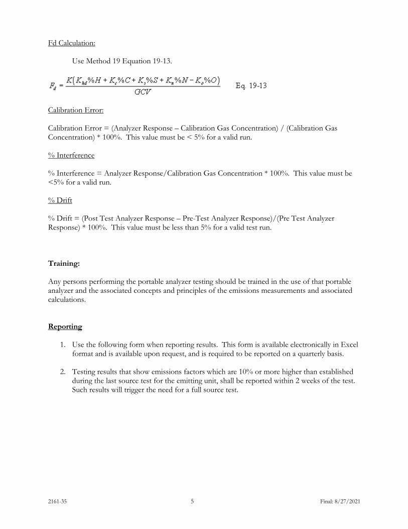
2161-35 5 Final: 8/27/2021
Fd Calculation: Use Method 19 Equation 19-13.
Calibration Error: Calibration Error = (Analyzer Response – Calibration Gas Concentration) / (Calibration Gas Concentration) * 100%. This value must be < 5% for a valid run. % Interference % Interference = Analyzer Response/Calibration Gas Concentration * 100%. This value must be <5% for a valid run. % Drift % Drift = (Post Test Analyzer Response – Pre-Test Analyzer Response)/(Pre Test Analyzer Response) * 100%. This value must be less than 5% for a valid test run. Training: Any persons performing the portable analyzer testing should be trained in the use of that portable analyzer and the associated concepts and principles of the emissions measurements and associated calculations. Reporting
1. Use the following form when reporting results. This form is available electronically in Excel format and is available upon request, and is required to be reported on a quarterly basis.
2. Testing results that show emissions factors which are 10% or more higher than established
during the last source test for the emitting unit, shall be reported within 2 weeks of the test. Such results will trigger the need for a full source test.

2161-35 6 Final: 8/27/2021
Tester Name Ambient Temperature (°F)
Tester SignatureBarometric Pressure (" Hg)
Tester Title and Affiliation: Date
Emitting Unit Name as indicated in MAQPFuel Factor (Fd) (dscf/MMBtu, as determined via Method 19 ultimate analysis on fuel burned on the testing date)Time StartTime StopCheck Zero NOxCheck Zero COCheck Zero O2Check Span NOx (ppm)Check Span CO (ppm)Check Span O2 (ppm)Measured NOx (ppm)Measured CO (ppm)% O2Flue Gas Temp. (°F)Moisture (%)Check Zero NOxCheck Zero COCheck Zero O2Check Span NOx (ppm)Check Span CO (ppm)Check Span O2 (ppm)NOx Calibration Error (%)NOx Interference (%)NOx Drift (%)CO Calibration Error (%)CO Interference (%)CO Drift (%)average % firing rateMaximum Rated Design Capacity (MMBtu/hr)Estimated lb/MMBtu emissions rate:
notes : See Appendix 2 of the MAQP for equations , testing requirements , QA/QC requirements , and etc.
Calumet Portable Analyzer Emission CheckMonthly Monitoring Report
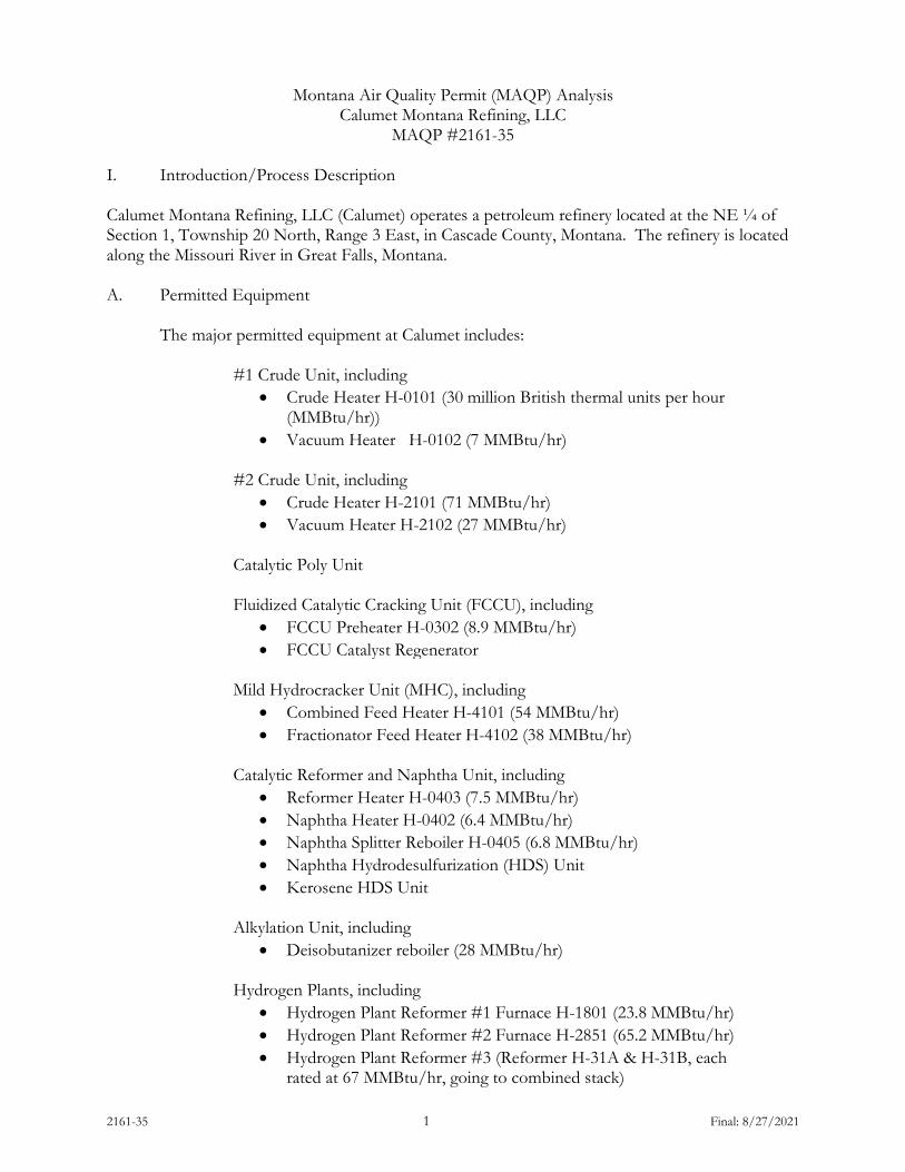
2161-35 1 Final: 8/27/2021
Montana Air Quality Permit (MAQP) Analysis Calumet Montana Refining, LLC
MAQP #2161-35 I. Introduction/Process Description Calumet Montana Refining, LLC (Calumet) operates a petroleum refinery located at the NE ¼ of Section 1, Township 20 North, Range 3 East, in Cascade County, Montana. The refinery is located along the Missouri River in Great Falls, Montana. A. Permitted Equipment
The major permitted equipment at Calumet includes: #1 Crude Unit, including
• Crude Heater H-0101 (30 million British thermal units per hour (MMBtu/hr))
• Vacuum Heater H-0102 (7 MMBtu/hr)
#2 Crude Unit, including
• Crude Heater H-2101 (71 MMBtu/hr) • Vacuum Heater H-2102 (27 MMBtu/hr)
Catalytic Poly Unit
Fluidized Catalytic Cracking Unit (FCCU), including
• FCCU Preheater H-0302 (8.9 MMBtu/hr) • FCCU Catalyst Regenerator
Mild Hydrocracker Unit (MHC), including
• Combined Feed Heater H-4101 (54 MMBtu/hr) • Fractionator Feed Heater H-4102 (38 MMBtu/hr)
Catalytic Reformer and Naphtha Unit, including
• Reformer Heater H-0403 (7.5 MMBtu/hr) • Naphtha Heater H-0402 (6.4 MMBtu/hr) • Naphtha Splitter Reboiler H-0405 (6.8 MMBtu/hr) • Naphtha Hydrodesulfurization (HDS) Unit • Kerosene HDS Unit
Alkylation Unit, including
• Deisobutanizer reboiler (28 MMBtu/hr)
Hydrogen Plants, including
• Hydrogen Plant Reformer #1 Furnace H-1801 (23.8 MMBtu/hr) • Hydrogen Plant Reformer #2 Furnace H-2851 (65.2 MMBtu/hr) • Hydrogen Plant Reformer #3 (Reformer H-31A & H-31B, each
rated at 67 MMBtu/hr, going to combined stack)

2161-35 2 Final: 8/27/2021
Hydrotreater Unit (HTU) Unit, including
• Kerosene Heater • HTU Heater H-1701 (20.3 MMBtu/hr)
Sodium Hydrosulfide (NaHS) Unit
Polymer-Modified Asphalt (PMA) Unit, including
• D-1901 – wetting tank (New larger tank added in MAQP #2161-35)
• RT-1901 – reactor tank
PMA Unit Prilled Sulfur Handling Operations Product Loading, including
• Truck Loading with Vapor Combustion Unit (VCU) • Railcar Loading with VCU • Railcar Loading (diesel and asphalt)
Utilities • Boilers #1 & #2 with maximum rated capacity of 25 MMBtu/hr
each • Boiler #3 with maximum capacity of 60.5 MMBtu/hr • Wastewater
Surge Tank T-143, 18,000 bbl external floating roof Surge Tank T-145, 37,000 bbl external floating roof Aeration Tank TK-146 Slop Oil Tank 144, 600 bbl Slop Oil Tank 144B, 300 bbl Slop Oil Tank 186, 600 bbl each API Separator DAF Unit (Existing and New DAF unit in series) Drains
• North and South Cooling Towers Storage Tanks, including:
Tank 1: 152 bbl, Fixed Roof in Jet Fuel Additive service Tank 2: 800 bbl Pressure Vessel in Propane service Tank 3: 2,000 bbl Pressure Vessel in Isobutane service Tank 4: 600 bbl Pressure Vessel in Butane service Tank 5: 600 bbl Pressure Vessel in Isobutane service Tank 10: 375 bbl Fixed Roof tank in Transmix service Tank 14: 1,400 bbl Pressure Vessel in Isobutane service Tank 15: 1,400 bbl Pressure Vessel in Butane service Tank 29: 20,600 bbl Fixed Roof in Distillate service Tank 47: 20,500 bbl Fixed Roof in Kerosene/ Jet Fuel service Tank 48: 20,500 bbl Fixed Roof in Kerosene / Jet Fuel service Tank 49: 20,500 bbl Fixed Roof in Kerosene / Jet Fuel service
2161-35 3 Final: 8/27/2021
Tank 50: fixed roof tank in asphalt storage service Tank 51: 21,000 bbl Fixed Roof in Kerosene / Jet Fuel service Tank 52: 19,000 bbl External Floating Roof in Gasoline service Tank 54: 18,000 bbl Fixed Roof in Kerosene / Jet Fuel service Tank 57: 10,000 bbl Internal Floating Roof in Naphtha service Tank 58: 9,900 bbl Fixed Roof in Kerosene / Jet Fuel service Tank 100: 1,100 bbl Fixed Roof in #5 Fuel Oil service Tank 101: 1,100 bbl Fixed Roof in #5 Fuel Oil service Tank 102: fixed roof tank in asphalt storage service Tank 116: 44,900 bbl Fixed Roof in Distillate service Tank 118: 2,000 bbl Fixed Roof in Asphalt Emulsion service Tank 119: 2,000 bbl Fixed Roof in Asphalt Emulsion service Tank 120: 2,200 bbl Fixed Roof in Asphalt Emulsion service Tank 121: 2,200 bbl Fixed Roof in Asphalt Emulsion service Tank 122: 21,900 bbl External Floating Roof in Gasoline service Tank 123: 21,900 bbl External Floating Roof in Gasoline service Tank 124: 21,500 bbl External Floating Roof in Naphtha service Tank 125: 38,500 bbl Fixed Roof in Heavy Liquids Service Tank 126: 29,500 bbl External Floating Roof in Gasoline service Tank 127: 21,500 bbl External Floating Roof in Gasoline service Tank 128: 21,500 bbl Fixed Roof in Heavy Liquids Service Tank 137: Fixed Roof in Asphalt Storage service Tank 138: Fixed Roof in Asphalt Storage service Tank 139: Fixed Roof in Asphalt Storage service Tank 140: Fixed Roof in Asphalt Storage service Tank 150: 30,100 bbl Fixed Roof in Raw Kerosene service Tank 170: 10,200 bbl Fixed Roof in Distillate service Tank 171: 10,200 bbl Fixed Roof in Distillate service Tank 175: 400 bbl Fixed Roof in Ethanol service Tank 176: 5,000 bbl Internal Floating Roof in Ethanol service Tank 201: 69,700 bbl External Floating Roof in Crude Oil service Tank 202: 69,700 bbl External Floating Roof in Crude Oil service Tanks Added Under MAQP #2161-35 Tank #55: 3,022 bbl in Asphalt Service Tank #130: 1,007 bbl for PMA Preparation Tank #132: 1,007 bbl for PMA Preparation Tank #133: 1,007 bbl for PMA Preparation D-1906: 55 bbl Hot Oil Expansion Tank D-1908: 55 bbl Hot Oil Expansion Tank D-1907: 72 bbl Crosslinking Tank Stationary Internal Combustion Engines: GEN1: 400 hp diesel fired Emergency Generator
AC1: 540 hp diesel fired Emergency Air Compressor Engine WP1: 165 hp, diesel fired Emergency Storm Water Pump WP2: 240 hp, diesel fired Tank 54 Emergency Fire Water Pump WP3: 300 hp, diesel fired Tank 24 Emergency Fire Water Pump WP4: 300 hp, diesel fired Tank 146 Emergency Fire Water Pump
2161-35 4 Final: 8/27/2021
Electric Catalytic Thermal Oxidizer for the AOC-16 Remediation Project
B. Source Description
Petroleum refining has been conducted at this site since the early 1920’s. Calumet converts crude oil into a variety of petroleum products, including gasoline, diesel fuel, jet fuel, naphtha, asphalt, and NaHS.
C. Permit History
On December 2, 1985, the Montana Department of Health and Environmental Sciences and Montana Refining Company (MRC) signed a stipulation requiring MRC to obtain an air quality permit, and stipulated that a permit emission limitation of 4,700 tons per year (TPY) carbon monoxide (CO) would constitute compliance with ambient CO standards. MRC submitted this permit application with the intentions of permitting its existing refining operations, including all equipment not already permitted.
On October 20, 1985, MRC was granted a general permit for their petroleum refinery and major refinery equipment located in Great Falls, Cascade County, Montana. The application was given MAQP #2161. The first alteration to their original permit was given MAQP #2161-A and was issued on May 31, 1989. This alteration involved the addition of a deisobutanizer reboiler. The second alteration was given MAQP #2161-A1 and was issued on March 12, 1990. This project involved the installation of one 30,000-barrel gasoline storage tank and one 40,000-barrel crude oil storage tank at the present facility. Both tanks were installed with external floating roof control. The third alteration was given MAQP #2161-A3 and was issued on December 18, 1990. This alteration consisted of the installation of a Hydrofluoric (HF) Acid Alkylation Unit, internal floating roofs at existing storage tanks, which had fixed roofs, and a safety flare. The fourth alteration was given MAQP #2161-04 and was issued on June 16, 1992. This alteration consisted of the installation of a NaHS unit at the existing Great Falls Refinery. The NaHS unit receives refinery fuel gas (540,000 standard cubic foot per day (scf/day) maximum rated capacity) containing hydrogen sulfide (H2S) and reacts with a sodium hydroxide caustic solution to remove virtually 100% of the H2S by converting it to NaHS, a saleable product. The resultant sweet fuel gas is burned, as before, in other process heaters. However, since the fuel gas contains virtually no H2S, sulfur dioxide (SO2) emissions from the process heaters, assuming no other changes, were decreased by nearly 60%. There was no decrease in permitted SO2 emissions from this permit because the refinery wanted to retain the existing permitted SO2 emission limitations, so it could charge less expensive, higher sulfur crude oil. In the basic process, off-gases from product desulfurizing processes (fuel gases) are contacted with a caustic solution in a gas contractor. The resultant reaction solution is

2161-35 5 Final: 8/27/2021
continually circulated until the caustic solution is essentially used up; NaHS product is then sent to storage. Make-up caustic is added to the process as required. The process requires a gas contractor, process heat exchanger, circulation pump, storage tanks for fresh caustic and NaHS product, 12 pipeline valves, 4 open-ended valves, 21 flanges, and other process control equipment. The only process emissions are fugitive Volatile Organic Compounds (VOC) from equipment (valves and flanges) in fuel gas stream service. To estimate unit VOC emissions, emission factors developed by the Environmental Protection Agency (EPA) for equipment in gas vapor service with measured emissions from 0 to 1,000 parts per million (ppm) are used. With an aggressive monitoring and maintenance program, fugitive VOC emissions from valves and flanges are within this 0 to 1,000-ppm range. Total annual fugitive VOC emissions from the NaHS units are estimated to be 20 pounds per year. The tank that is to be used to store NaHS product was in jet fuel service. When taken out of jet fuel service, this tank (#35) is no longer a source of VOC emissions; the reduction in VOC emissions will be 2,270 pounds per year (PPY). Considering the 2,270-PPY decrease due to tank #35 service change, the refinery realized a net decrease in annual VOC emissions of 2,250 PPY or 1.1 TPY. The fifth alteration was given MAQP #2161-05 and was issued on October 15, 1992. This permit alteration was for the construction and operation of two 20,000-barrel capacity aboveground storage tanks at its Great Falls Refinery. The new tanks contain heavy naphtha (#127) and raw diesel (#128). Each tank was constructed of metal sections welded together that rest on a concrete ring wall foundation. External floating roofs with dual seals are installed on each tank for VOC control. On April 6, 1993, MRC was granted MAQP # 2161-06 to construct and operate a HDS unit and hydrogen plant. This sixth alteration was required to go through New Source Review (NSR) - Prevention of Significant Deterioration (PSD) review for Oxides of Nitrogen (NOX) and was deemed complete on February 22, 1993. The HDS project was designed to process 5,000 barrels per day (BPD) of diesel/gas oil and to reduce the sulfur content to 0.05 weight percent. The reduction of sulfur in diesel fuel and gasoline were mandated by the 1990 Clean Air Act Amendments and were accomplished by October 1993, and 1995, respectively. The desulfurizer unit operated by MRC was limited in size and throughput capacity to approximately 1,400 barrels per day. The HDS project consisted of an HDS process unit and heater, hydrogen plant with reformer heater, and the removal of storage tanks #40 through #43. Tanks #40 and #41, which processed gas oil, were discontinued. Tanks #42 and #43 that process raw diesel were also discontinued. Tanks #44 and #111 were changed to gas oil use and Tank #45 which serviced JP-4 was changed to gas oil use. On July 28, 1993, MAQP #2161-07, a modification to MRC's MAQP #2161-06, was issued to change the emission control requirements of the Section titled "Pressure Vessels." In a system where the valves relieve to atmosphere, rupture discs can prevent emissions in the event of relief valve leakage. In HF systems, they can provide some protection from
2161-35 6 Final: 8/27/2021
acid corrosion on the relief valve and acid salt formation. Except where HF acid is present, rupture discs do not provide any additional protection nor do they prevent any release of air contaminates in a closed relief system. In heavy liquid service, rupture discs can be safety hazards by partial failure or leaking and changing, over time, the differential pressure required providing vessel protection. Therefore, only pressure vessels in HF Acid service shall be equipped with rupture discs upstream of the relief valves and all except storage tanks shall be vented to the flare system. Also, the allowable particulate emission limitation for MRC's FCCU was corrected to reflect the maximum allowable emissions based on the process weight rule (Administrative Rules of Montana (ARM) 17.8.310). The maximum allowable emissions were calculated to be 234.53 TPY using a catalyst circulation rate of 125 tons per hour (TPH). MRC requested a permit modification, MAQP #2161-08, to remove the alkylation unit and tanks #127 and #128 from New Source Performance Standards (NSPS) status because they were erroneously classified as affected facilities under NSPS when originally permitted. This request for modification was submitted on August 11, 1993, and issued on January 6, 1994. When MRC applied for the preconstruction permit to build the HF Alkylation Unit in 1990, it was presumed, since this unit was new to MRC, it automatically fell under NSPS as new construction. Subsequently, it has been determined that if a source is moved as a unit from a location where operation occurred (Garden City, Kansas) to another location, it must meet the definition of reconstruction or modification in order to trigger NSPS applicability. The alkylation plant was originally constructed in Garden City, Kansas during 1959 - 1960 and moved, in its entirety, to Great Falls and installed. Since the unit was originally constructed before the NSPS-affected date of January 5, 1981, it does not meet the criteria for construction date of a new source under 40 Code of Federal Regulations (CFR), Subpart GGG or Subpart QQQ. The project did not meet the criteria under reconstruction because no capital equipment was replaced when the unit was relocated. The replacement work performed, as the unit was moved, amounted to pump seals, valve packing, bearings, small amounts of corroded piping, and some heat exchanger tubes and bundles, all of which are done routinely as maintenance. The VOC emitters, such as valve packing and pump seals, were upgraded to meet Best Available Control Technology (BACT). Along the same line, tanks #127 and #128 were originally constructed at Cody, Wyoming in 1960 and relocated to Great Falls in 1993. The only change was the modification of the roof seals to double seals to meet BACT. This cost of modification was a total of $15,000 for both tanks as compared to more than $500,000 if two new tanks were to be built. Also, on October 28, 1993, MRC submitted a permit application to alter the existing permit. This modification and alteration of the existing permits were assigned MAQP #2161-08. MRC proposed to construct and operate a 3,500 barrel-per-day asphalt polymerization unit. The unit enabled MRC to produce a polymerized asphalt product that would meet future federal specifications for road asphalt, as well as supply polymerized asphalt to customers that wished to use the product. The proposed unit consisted of two circuits: the asphalt circuit and the hot oil circuit. In the asphalt circuit, polymerization occurs in a 1,000-barrel steel, vented mix tank. Product
2161-35 7 Final: 8/27/2021
blending and storage occurs in 3 steel, vented 1,000 barrel tanks identified as A, B, and C. Existing Tanks #55 and #56 (3,000 barrels each) remained in asphalt service and are used for storage. In addition to the above equipment, the asphalt circuit also consisted of 4 pumps and approximately 47 standard valves. All the above equipment became part of the asphalt service and, except for Tanks #55 and #56, was new. To maintain the asphalt at the optimum temperature in the storage and blending tanks, a hot circuit was utilized. Hot oil (heavy fuel oil) was heated in an existing permitted process heater (Tank #56 heater) and circulated through coils in the process tankage. No change in the method of operation of the heater was anticipated. A steel, vented hot-oil storage/supply tank was utilized to maintain the required amount of hot oil in the unit. In addition to the process heater and storage/supply tank, the hot-oil circuit consisted of one pump and approximately 56 standard valves. The above equipment was used in hot-oil service and, except for the heater, was new. An annual emissions increase of 7.3 TPY of VOC was expected due to operation of the unit. It was anticipated that the unit would be operated only 6 months of the year. The VOC emissions resulted from the vented hot-oil tank and the valves and pump in hot-oil service. MAQP #2161-09 was issued on September 6, 1994, and included a change in the method of heating three previously permitted polymer modified asphalt tanks. As previously permitted, these tanks were heated utilizing circulating hot oil. The tanks were heated individually using natural gas fired fire-tube heaters. The use of natural gas eliminated the hot-oil circuit, including the hot-oil storage tank, entirely. Since the initial permit application for the modified asphalt unit, several small design changes occurred involving the addition of a new 800-gallon wetting tank for asphalt service. An output line from existing Tank #69 (Tall Oil) was also added. This output line added approximately 12 new valves and one new pump, all in Tall Oil service, to the unit. All other valves and pumps were designated to be in asphalt service. All VOC emissions from equipment and tanks in asphalt service were assumed to be negligible, since asphalt has negligible vapor pressure at the working temperatures seen in the unit. MAQP #2161-10, for the installation of an additional boiler (Boiler #3) to provide steam for the facility, was never issued as a final permit. On May 28, 1997, the Department of Environmental Quality – Air Resources Management Bureau (Department) received a letter requesting the withdrawal of the permit application and the withdrawal was granted to MRC. A summary of this permitting action is included in the analysis for MAQP #2161-11. MAQP #2161-11 was issued on January 23, 1998, for the installation of a vapor collection system and enclosed flare for the reduction of Hazardous Air Pollutants (HAP) resulting from the loading of gasoline. This was done in order to comply with the gasoline loading rack provisions of 40 CFR 63, Subpart CC - National Emission Standards (NES) for Petroleum Refineries. A VCU was added to the truck loading rack. The gasoline vapors are collected from the trucks during loading then routed to an enclosed flare where combustion occurs. The result of this project was an overall reduction in the amount of VOC and HAPs emitted, and a slight increase in CO and NOx emissions. Because MRC’s bulk gasoline and distillate truck loading rack VCU was defined as an

2161-35 8 Final: 8/27/2021
incinerator under Montana Code Annotated (MCA) 75-2-215, a determination that the emissions from the VCU would constitute a negligible risk to public health was required prior to the issuance of a permit to the facility. MRC and the Department identified the following HAPs from the flare that was used in the health risk assessment. These constituents are typical components of MRC's gasoline. 1. Benzene 2. Toluene 3. Ethyl Benzene 4. Xylenes 5. Hexane 6. 2,2,4-Trimethlypentane 7. Cumene 8. Naphthalene 9. 1,3-Butadiene The reference concentrations for Benzene, Toluene, Ethyl Benzene, and Hexane were obtained from EPA’s IRIS database. The risk information for the remaining HAPs was contained in the January 1992 CAPCOA Risk Assessment Guidelines. The ISCT3 modeling performed by MRC for HAPs identified above demonstrated compliance with the negligible risk requirement. MRC requested, via a letter dated August 13, 1997, changes to administratively and technically correct MAQP #2161-09. These changes were necessary as a result of the withdrawal of MAQP #2161-10. The changes included correctly stating opacity limits relating to asphalt storage tanks, removing references to procedural rules, changing monitoring requirements for the HTU Sour Water Stripper (SWS) and changing performance specifications for the continuous H2S monitoring system. The Department issued Draft Modification #2161-11 on November 6, 1997, to address the permit changes that were requested by MRC. The Department received comments on November 13, 1997, from MRC and later met on November 17, 1997, to discuss the draft modification. Because MRC had applied for a permit alteration on October 21, 1997, for the loading rack VCU, the draft modification was addressed in the permit alteration request. The Department issued Preliminary Determination #2161-11 on November 26, 1997. The Department received comments from MRC on December 4, 1997, December 10, 1997, December 15, 1997, and December 30, 1997. The Department responded to these comments via faxes on December 8, 1997, December 11, 1997, and December 16, 1997. On December 23, 1997, the Department was prepared to issue a Department Decision, but MRC requested, via telephone, that the decision not be issued until after the holidays. The decision was required to be issued by January 8, 1998, to meet the mandated time frames for issuing a Department Decision. MAQP #2161-12 was not issued. MRC applied for a modification on February 18, 1998, and this action was given #2161-12. On February 27, 1998, the Department notified MRC that the permitting actions requested would require an alteration and that a complete preconstruction permit application would be required.

2161-35 9 Final: 8/27/2021
MAQP #2161-13 placed enforceable emission limits on the facility, both plant-wide and the #1 and #2 boilers. The emission limits showed, through the use of EPA-approved models, to protect the National Ambient Air Quality Standards (NAAQS) for SO2. The continuous gas flowmeters installed on the vacuum heater and the crude heater were placed in the permit. Also, the #1 and #2 boiler limits were updated to allow MRC more flexibility in their operations. The limits were originally placed on the boilers to keep MRC below the PSD permitting threshold. The new limits maintained MRC’s status below the PSD permitting threshold. The monitoring location was identified in Attachment 1 Ambient Air Monitoring Plan. The current location was determined to be inappropriate after reviewing the modeling analysis, and the new location was approximately 1.2 km from its present location. The monitoring location was chosen based on the modeling analysis that was submitted and is required to provide monitored confirmation of compliance with the Montana SO2 Standards. The method numbers for examination of water and wastewater were updated. The conditions in MAQP #2161-13 were incorporated into the Operating Permit and the compliance demonstration methodology for those conditions was evaluated at the time of the Operating Permit’s issuance. MAQP #2161-13 replaced MAQP #2161-11. On August 4, 2001, the Department issued MAQP #2161-14 for the installation and operation of five 1600-kilowatt (kW) diesel-powered, temporary generators. These generators were necessary because of the current high cost of electricity. The generators would only operate for the length of time necessary for MRC to acquire a permanent, more economical, supply of power. Further, the generators are limited to a maximum operating period of 2 years. Because these generators would only be used when commercial power is cost prohibitive, the amount of emissions expected during actual operation is minor. In addition, because the permit limits the operation of these generators to a time period of less than 2-years, the installation and operation qualifies as a "temporary source" under the PSD permitting program. Therefore, the proposed project does not require compliance with ARM 17.8.804, 17.8.820, 17.8.822, and 17.8.824. Even though the portable generators are considered temporary, the Department requires compliance with BACT and public notice requirements; therefore, compliance with ARM 17.8.819 and 17.8.826 will be ensured. Finally, MRC is responsible for complying with all applicable ambient air quality standards. MAQP #2161-14 replaced MAQP #2161-13. On August 17, 2002, the Department issued MAQP #2161-15 to eliminate the summer boiler SO2 emission limits (both the plant-wide and 24-hour average) and redefine the winter limits as year-round limits. The seasonal limits were originally placed in the permit to allow MRC more flexibility when operating the boilers. Both the winter and summer scenarios were supported by ambient air quality modeling performed prior to MAQP #2161-13 being issued. The winter limit being redefined as a year-round limit does not represent an increase in SO2 emissions from the boilers or any other emitting point. In addition, the Department removed requirements to determine and report NOX emissions both from the crude heater (due to the old SWS) and refinery wide, as these sources are not subject to NOX emissions limitations. The requirements appeared to have been inadvertently applied through an administrative error. MRC already provides refinery-wide NOX emissions as part of its
2161-35 10 Final: 8/27/2021
annual Emission Inventory submission to the Department. MAQP #2161-15 replaced MAQP #2161-14. On March 19, 2003, the Department issued MAQP #2161-16 to include certain limits and standards associated with the Consent Decree lodged on December 20, 2001. In addition, the permit was updated with new rule references under ARM 17.8, Subchapter 7. MAQP #2161-16 replaced MAQP #2161-15. The Department received a request to modify MAQP #2161-16 on July 10, 2003, to change the emission testing schedule for the gasoline truck loading vapor combustion unit to be consistent with MRC’s current operating permit. MRC also requested the Department clarify the 7,000-BPD limit of crude charge (referenced in MRC’s Title V Operating Permit) is no longer valid. Should MRC’s normal processing exceed 7,000-BPD, MRC would be required to comply with ARM 17.8.324, as applicable. In a letter received by the Department on September 30, 2003, MRC also requested to add three new asphalt tanks with associated natural gas heaters. The emissions from the three tanks met the requirements of the de minimis rule and were added to the permit. The permit action updated the permit to reflect the changes. MAQP #2161-17 replaced MAQP #2161-16. On May 14, 2004, the Department received a letter from MRC requesting changes to MAQP #2161-17. The proposed change includes adding the ability to burn sweet gas in heaters at the HF Alkylation Unit, and at Tanks 102, 135, 137, 138, and 139. The sweet gas will have a H2S limit equivalent to the 40 CFR Part 60, Standards of Performance for NSPS, Subpart J limit of 0.10 grains per dry standard cubic foot (gr/dscf) H2S. The continuous refinery fuel gas monitoring system for H2S installed on the fuel gas system that supplies the heaters would be used to determine compliance with the limit. Since the emissions from switching the fuel to sweet gas were less than the de minimis threshold, the Department added the fuel switch. The permit action updated the permit to reflect these changes. MAQP #2161-18 replaced MAQP #2161-17. On May 17, 2007, the Department received an application from MRC for the installation of a railcar product loading rack controlled by a John Zink VCU. On June 19, 2007, MRC clarified that gasoline and naphtha were the only products that will go through the new railcar loading rack, and that other liquid products already loaded into railcars (diesel, jet fuel, etc.) would not be affected. The gasoline railcar loading rack is subject to 40 CFR 63, Subpart CC, which requires MRC to comply with specific bulk loading requirements in 40 CFR 63, Subpart R. Subpart R restricts the operation of the railcar loading system to less than 10 milligrams (mg) of VOC per liter of gasoline loaded and requires the operation of a continuous monitor downstream from the firebox. Furthermore, the gasoline and naphtha railcars are considered as ‘gasoline cargo tanks’ and are required to comply with the leak detection testing requirements. Lastly, 40 CFR 63, Subpart CC requires MRC to comply with 40 CFR 60, Subpart VV to minimize fugitive equipment leaks. Other new applicable regulations were added, including 40 CFR 63, Subpart UUU, Subpart EEEE, and Subpart DDDDD. Consent Decree #CIV-01-1422LH requirements, entered March 5, 2002 (Consent Decree), were included, such as the new requirements to comply with 40 CFR 60, Subpart J limits for refinery fuel gas and SWSOH. Other changes completed in this permit action were: adding FCCU uncorrected CO emissions from 40 CFR 63, Subpart UUU, and SO2 and NOX emission limits resulting from the Consent

2161-35 11 Final: 8/27/2021
Decree; and revising the permit to reflect the operation of a continuous H2S fuel gas meter and requirement to comply with 40 CFR 60, Subpart J. MAQP #2161-19 replaced MAQP #2161-18. On October 15, 2007, the Department received letter from MRC requesting a correction to MAQP #2161-19, to remove the restrictions on the type of fuel used in specific asphalt tank heaters, which was added erroneously during the previous permitting action. In addition, the MAQP was updated to reflect the fact that requirements under 40 CFR 63, Subpart DDDDD are now “state-only” since the federal rule was vacated in Federal Court on July 30, 2007. MAQP #2161-20 replaced MAQP #2161-19. On June 9, 2008, the Department received a letter from MRC requesting an amendment to MAQP #2161-20, to modify the restrictions on Storage Tank #8. This request was a follow-up to a de minimis request received by the Department on April 21, 2008, where MRC proposed to change the operation of Storage Tank #8 from NaHS to naphtha. The Department reviewed this de minimis request and determined that MAQP #2161-20 must first be amended as described in the ARM 17.8.745(2) and ARM 17.8.764 before this change would be allowed. Although the potential emissions increase for this project is less than the de minimis threshold, the proposal would have violated a condition of MRC’s current permit. Specifically, the MAQP states, “Storage tanks #8, #9, #50, #55, #56, #69 #102, #110, #112, #130, #132, #133, and #135 shall be used for asphalt, modified asphalt, or tall oil service (ARM 17.8.749).” This permit has been amended to allow the proposed change in operation of Storage Tank #8. On July 2, 2008, the Department received another letter from MRC requesting an administrative amendment to MAQP #2161-20 to include certain conditions specified in the Administrative Order on Consent (AOC) that MRC entered into with the Department on May 13, 2008. The AOC requires MRC to install and operate a SO2 and Oxygen (O2) continuous emission monitor system (CEMS) on the stack for the #1 and #2 Boilers. This SO2/O2 CEMS is to be used as the primary analytical instrument to determine compliance with state and federal SO2 requirements. The AOC requires MRC to request that these conditions be included in the MAQP as enforceable permit conditions. In addition, MRC requested that the permit be amended to allow certain de minimis changes related to the Diesel/Gas Oil HDS heater and three PMA tank heaters. Specifically, MRC requested that refinery fuel gas, in addition to natural gas, be allowed to be burned in these heaters. The current permit requires that the Diesel/Gas Oil HDS heater and the three PMA tank heaters be fired only with natural gas. This requirement is based on BACT. For the Diesel/Gas Oil HDS heater, the BACT analysis requires that low sulfur fuel be used. Since the refinery fuel gas is also a low sulfur fuel meeting 40 CFR 60, Subpart J requirements of 160 ppm H2S, the Department determined that the proposed change does not violate any applicable rule and therefore, can be allowed through an administrative amendment as specified in ARM 17.8.745(2) and ARM 17.8.764. For the three PMA tank heaters, however, the BACT analysis specifically requires that these heaters be fired with natural gas for control of NOx emissions. Therefore, the Department determined that the proposed three PMA tank heaters de minimis changes are prohibited under ARM 17.8.745(1)(a)(i) since an applicable rule, specifically ARM 17.8.752 requiring that BACT be utilized, would be violated. Because BACT determinations cannot be changed under the amendment process, the Department requested that MRC submit an application for a permit modification that would include a revised BACT analysis in order to make the proposed change for the three PMA tank heaters.

2161-35 12 Final: 8/27/2021
In addition, the Department updated Attachment 1 to reflect the most current permit language and requirements for ambient monitoring. MAQP #2161-21 replaced MAQP #2161-20. On December 19, 2008, the Department received a request from MRC to amend MAQP #2161-21. MRC requested to change the wording for material stored in specified storage tanks to language representative of the requirements of 40 CFR 60, Subpart Kb in order to provide operational flexibility. Instead of referring to specific products (e.g., naphtha, gasoline, diesel, tall oil, etc.), the products would instead be referred to as light oils, medium oils, and heavy oils. Under MRC’s proposed language, light oils would be defined as a volatile organic liquid with a maximum true vapor pressure greater than or equal to 27.6 kilopascal (kPa), but less than 76.6 kPa and would include, but not be limited to, gasoline and naphtha. Medium oils would be defined as volatile organic liquids with a vapor pressure less than 27.6 kPa and greater than or equal to 5.2 kPa and would include, but not be limited to, ethanol. Heavy oils would be defined as volatile organic liquid with a maximum true vapor pressure less than 5.2 kPa and would include, but not be limited to diesel, kerosene, jet fuel, slurry oil, and asphalt. In addition to making the requested change, the Department has clarified the permit language for the bulk loading rack VCU regarding the products that may be loaded in the event the VCU is inoperable and deleted all references to 40 CFR 63, Subpart DDDDD: NESHAP for Industrial, Commercial, and Institutional Boilers and Process Heaters, as it was removed from the ARM in October 2008. The Department has also updated Attachment 1, Ambient Monitoring to reflect the most current permit language and requirements for ambient monitoring. MAQP #2161-22 replaced MAQP #2161-21. On July 9, 2009, the Department received a permit application from MRC to modify MAQP #2161-22. The application was deemed complete on July 24, 2009. MRC submitted a permit modification to allow the use of treated refinery fuel gas or natural gas in the tank heaters. Previously, the PMA tanks heaters were permitted to use natural gas only pursuant to a BACT analysis that was completed for MAQP #2161-09. This permit modification applied to three previously permitted asphalt tanks (Tanks #130, 132 and 133) and the associated PMA tank heaters. MAQP #2161-23 replaced MAQP #2161-22. On January 15, 2008, the Department received a request from MRC to install a second hydrogen plant that utilizes a process heater with a heat input of 80 million British thermal units per hour (MMBtu/hr). The Department approved this de minimis request on February 8, 2008. Pursuant to the Consent Decree (CD) and the approval of the de minimis request, MRC was required to conduct an initial performance test on the process heater with the results reported based upon the average of three, one-hour testing periods. The CD also required MRC to submit an application to the Department and to propose a NOx permit limit for the heater. MRC submitted a permit application on December 29, 2009 and the Department deemed this application incomplete on January 15, 2010. On July 12, 2010, MRC submitted additional information as requested by the Department. On September 2, 2010, during the comment period, MRC submitted information to support the guaranteed ultra-low NOx burner emission limit of 0.033 lb/MMBtu based on the Higher Heating Value (HHV) of the fuel. This limit was based on the process heater of the hydrogen plant operating at full capacity (80 MMBtu/hr) with fuel gas consisting of 40.5 % natural gas and 59.4% Pressure Swing Adsorption (PSA) vent gas. This permit modification applied to NOx

2161-35 13 Final: 8/27/2021
limits on the Hydrogen Plant #2 process heater. MAQP #2161-24 replaced MAQP #2161-23. On July 6, 2011, MRC submitted a permit application and subsequent modeling demonstration to add a new boiler (Boiler #3) capable of firing refinery fuel gas, SWSOH, or natural gas at the petroleum refinery. The primary purpose of Boiler #3 is to supplement the two existing boilers (#1 and #2) that provide process steam to the refinery. The design burner heat input capacity for Boiler #3 varies, depending upon fuel characteristics, from 59.7 to 60.5 MMBtu/hr. The Department deemed the application incomplete on August 4, 2011, and MRC provided additional information in response to the Department’s letter on September 26, 2011. On October 25, 2011, the Department requested additional information with respect to MRC’s plantwide applicability limit (PAL) and the SWSOH combustion properties. This information was received by the Department on November 15, 2011. Additionally, because MRC experienced significant downtime with the SO2/O2 CEMS required on the #1 and #2 Boiler stack, MRC submitted a request to allow the use of the H2S fuel gas analyzer located near the fuel gas drum as backup to the SO2/O2 CEMS. MRC also requested this for Boiler #3. Therefore, in addition to adding the Boiler #3 to the refinery’s operation, the permit action also added compliance, reporting and recordkeeping requirements for allowing the H2S fuel analyzer to be used as a backup to the SO2/O2 CEMS. When the H2S fuel analyzer is used, MRC would not be allowed to route the SWSOH to the boilers. MAQP #2161-25 replaced MAQP #2161-24. On October 24, 2012, the Department received a request for the transfer of ownership. According to the information submitted, the previous owner, Connacher Oil and Gas, sold its shares of MRC to Calumet Specialty Products Partners. With the transfer of ownership, Calumet Specialty Products Partners also requested a facility name change from MRC to Calumet Montana Refining, LLC. This was an administrative permit action to change the name. MAQP #2161-26 replaced MAQP #2161-25. On July 30, 2013, the Department received an application for modification to MAQP #2161-26. The permit action removed older storage tanks that were located close to the process unit area and in order to accommodate potential future expansion. As such, Calumet requested to remove nine (9) tanks and to add eight (8) new tanks as shown in the table below:
Current Tank ID
Current Service
Current Capacity (in barrels (bbl))
New Tank ID
Service New Capacity (in bbl)
Tank #122 Unleaded Gasoline
11300 Tank #122 Unleaded Gasoline
20000
Tank #123 Unleaded Gasoline
11300 Tank #123 Unleaded Gasoline
20000
Tank #52 Premium Gasoline
3000 Tank #52 Premium Gasoline
11300
Tank #53 Premium Gasoline
3000 Removed from service
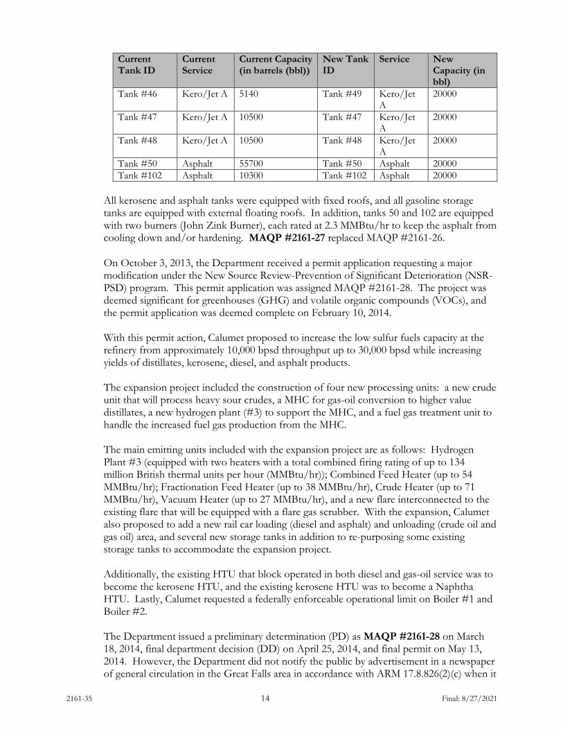
2161-35 14 Final: 8/27/2021
Current Tank ID
Current Service
Current Capacity (in barrels (bbl))
New Tank ID
Service New Capacity (in bbl)
Tank #46 Kero/Jet A 5140 Tank #49 Kero/Jet A
20000
Tank #47 Kero/Jet A 10500 Tank #47 Kero/Jet A
20000
Tank #48 Kero/Jet A 10500 Tank #48 Kero/Jet A
20000
Tank #50 Asphalt 55700 Tank #50 Asphalt 20000 Tank #102 Asphalt 10300 Tank #102 Asphalt 20000
All kerosene and asphalt tanks were equipped with fixed roofs, and all gasoline storage tanks are equipped with external floating roofs. In addition, tanks 50 and 102 are equipped with two burners (John Zink Burner), each rated at 2.3 MMBtu/hr to keep the asphalt from cooling down and/or hardening. MAQP #2161-27 replaced MAQP #2161-26. On October 3, 2013, the Department received a permit application requesting a major modification under the New Source Review-Prevention of Significant Deterioration (NSR-PSD) program. This permit application was assigned MAQP #2161-28. The project was deemed significant for greenhouses (GHG) and volatile organic compounds (VOCs), and the permit application was deemed complete on February 10, 2014. With this permit action, Calumet proposed to increase the low sulfur fuels capacity at the refinery from approximately 10,000 bpsd throughput up to 30,000 bpsd while increasing yields of distillates, kerosene, diesel, and asphalt products. The expansion project included the construction of four new processing units: a new crude unit that will process heavy sour crudes, a MHC for gas-oil conversion to higher value distillates, a new hydrogen plant (#3) to support the MHC, and a fuel gas treatment unit to handle the increased fuel gas production from the MHC. The main emitting units included with the expansion project are as follows: Hydrogen Plant #3 (equipped with two heaters with a total combined firing rating of up to 134 million British thermal units per hour (MMBtu/hr)); Combined Feed Heater (up to 54 MMBtu/hr); Fractionation Feed Heater (up to 38 MMBtu/hr), Crude Heater (up to 71 MMBtu/hr), Vacuum Heater (up to 27 MMBtu/hr), and a new flare interconnected to the existing flare that will be equipped with a flare gas scrubber. With the expansion, Calumet also proposed to add a new rail car loading (diesel and asphalt) and unloading (crude oil and gas oil) area, and several new storage tanks in addition to re-purposing some existing storage tanks to accommodate the expansion project. Additionally, the existing HTU that block operated in both diesel and gas-oil service was to become the kerosene HTU, and the existing kerosene HTU was to become a Naphtha HTU. Lastly, Calumet requested a federally enforceable operational limit on Boiler #1 and Boiler #2. The Department issued a preliminary determination (PD) as MAQP #2161-28 on March 18, 2014, final department decision (DD) on April 25, 2014, and final permit on May 13, 2014. However, the Department did not notify the public by advertisement in a newspaper of general circulation in the Great Falls area in accordance with ARM 17.8.826(2)(c) when it

2161-35 15 Final: 8/27/2021
issued the PD for MAQP #2161-28. Therefore, the Department reissued its PD under MAQP #2161-29 along with a public notice in the Great Falls Tribune to satisfy the requirements of ARM 17.8.826(2)(c). All project analyses and conclusions from MAQP #2161-28 for this project remained the same. MAQP #2161-29 contained any comments received on the PD for MAQP #2161-28 and corrections made to address them. On April 4, 2017 the Department received an application from Calumet to modify the existing MAQP. Incompleteness responses and additional information were received, with final information completing the application on September 26, 2017. Due to various operational and design issues, compliance with certain limits associated with the expansion project permitted in MAQP #2161-29 were determined to be unachievable on a continuous and ongoing basis. These limitations were necessary to avoid the project being determined a major modification of a major stationary source and subject to the permitting requirements of ARM 17.8 Subchapter 8 for NOX. As such, Calumet proposed an alternative operating scenario and alternative limitations to maintain the project below relevant significant emissions rates. Calumet proposed to install a new temporary low NOX boiler (Boiler #4) for additional/supplemental steam production and an ammonia combustor to remove and combust fuel bound nitrogen that otherwise would be present in refinery fuel gas. In addition, Calumet proposed an umbrella limit on emissions of NOX and CO on a rolling 12-month basis. The umbrella limit would apply to combined emissions from multiple units such that any combination of emissions from these units, provided the overall emissions limitation is adhered to, maintains the project as not a major modification for NOX or CO. Prior limitations related to PSD avoidance on Boilers #1 and #2 have been removed from the permit. Calumet has determined a need to reduce fuel-bound nitrogen in fuel gas in order to meet NOX limitations on various units. Further, Calumet has identified mechanical issues with Boiler #3 which has resulted in the potential for excess NOX emissions. Bringing a temporary low NOX boiler on-site will allow Calumet to produce steam for operations while ongoing efforts are undertaken to reduce plant wide NOX emissions. The low NOX boiler will provide for reduced emissions of NOX per pound of steam produced compared to the NOX performance capabilities of Boilers #1 and #2. Boiler #3, the new low NOX boiler, and the ammonia combustor were determined technically and economically related to the expansion project and were included in the expansion project as new units. The purpose of this permitting action is to establish limits which maintain the net emissions increases to less than the significant emissions rates for NOX and CO, or less than the amount of other emissions previously reviewed for the expansion project. All pollutants were reviewed, and the project was re-permitted as if the project had not been previously permitted. A request in the future to modify or replace associated units would require a reassessment of the project emissions. The allowable operating capacity of the associated refining unit heaters as a whole was reduced in the current operational scenario, and future projects to reduce emissions will be necessary to gain full use of the increased refining capacity capable of being accomplished with the associated equipment installed for avoidance of PSD. During PSD review, Calumet identified that Tank #50 and #102 will not be equipped with tank heaters and the emissions were removed from considerations in contemporaneous emissions increases. MAQP #2161-30 replaced MAQP #2161-29.

2161-35 16 Final: 8/27/2021
On July 12, 2019, the Department received from Calumet an application to modify the MAQP. Calumet sought to relax the control requirements on Tanks #125 and #128, due to a finding that the tanks are out-of-round, making seals associated with floating roof design to be infeasible to maintain. These tanks are in heavy liquid service, and as such, the Department approved request to maintain these tanks as fixed roof tanks with submerged fill. In doing so, the emissions increases associated with the expansion project is updated, and Best Available Control Technology (BACT) review is presented in demonstration that the requirements of BACT are maintained (see the permit analysis). Condition III.B.7.h was established to require the fixed roof tanks be maintained in heavy liquids service with submerged fill practices maintained. Prior requirements that these tanks be maintained with floating roof design was removed. MAQP #2161-32 replaced MAQP #2161-31.
On December 31, 2019, the Montana Department of Environmental Quality – Air Quality Bureau (Department) received from Calumet a concurrent MAQP and Title V application to revise nitrogen oxides (NOX) limitations on the #2 Crude Vacuum Heater H-2102 and the Mild Hydrocracker Reactor Fractionation Heater H-4102. These heaters were assigned NOX limitations as part of Best Available Control Technology (BACT) review associated with the refinery expansion project. The limits were originally set at 0.035 pounds per million British thermal units, on a higher heating value basis, on a 30-day rolling average. \ The permit application requested that these limits be revised to 0.040 lb/MMBtu, on a 3-hr basis via an annual source test. The permit action provided for an achievable limitation which is practically enforceable without a requirement for CEMS. The mass-based umbrella limitations for NOX and CO remained unchanged. MAQP #2161-33 replaced MAQP #2161-32.
On February 19, 2021, the Department of Environmental Quality – Air Quality Bureau (Department) received from Calumet an application to modify the MAQP for installation of a catalytic thermal oxidizer. Calumet implemented the AOC-16 Remediation Project at the Gasoline and Light Oil Loading Rack area, which included dual-phase extraction in an existing primary recovery trench in the truck rack area, and a passive treatment trench just north of North River Road. The installation of a vapor-liquid separator, with a catalytic thermal oxidizer to destroy VOC vapors, was included as part of this project.
In accord with ARM 17.8.770, a human health risk assessment on the air emissions from the catalytic thermal oxidizer was conducted. Further, a best available control technology review as required by ARM 17.8.752 was conducted. The analyses demonstrated the proposed oxidizer emissions would present a negligible risk to public health, safety, and welfare as defined in ARM 17.8.770, and meet the requirements of BACT as required by ARM 17.8.752. MAQP #2161-34 replaced MAQP #2161-33.
D. Current Permit Action
On July 2, 2021, the Department of Environmental Quality – Air Quality Bureau (Department) received from Calumet an application to modify the MAQP for installation of new equipment and tanks related to the polymer modified asphalt (PMA) production process. This project is titled the Asphalt Upgrades Project. The Asphalt Upgrades Project will provide the refinery with improved PMA production capabilities, more advanced asphalt product blending capabilities, and modernized heating systems for PMA process equipment, PMA storage tanks, and asphalt storage tanks. The project also includes the shutdown of

2161-35 17 Final: 8/27/2021
numerous heaters which will be replaced with heaters fired by refinery fuel gas. The project also makes changes to the asphalt product blending and storage operations at the refinery. MAQP #2161-35 replaces MAQP #2161-34.
E. Response to Public Comments
Person/Group Commenting
Permit Reference in PD
Comment Department Response
Calumet Section I.B Crossing-linking Tank will be identified as D-1907
Added to Description
Calumet Section I.C Tanks identified as new or existing, are all existing
Correction Made
Calumet Section II.A.f Tank 55 is not new and will be subject to Subpart UU
Correction Made
Calumet Section II.A.j The PMA unit will be subject to Subpart GGGa
Correction Made
Calumet Section II.B.7.i Tank #138 is missing from this list and the tanks may contain either asphalt or heavy oil
Correction Made
Calumet Section II.B.7.l Heaters #135, #137, and #139 are being removed as part of the project
Correction Made
Calumet Section II.B.7.n H-1903 and H-1904 will replace the tank heaters on tank #130, #132 and #133. They will burn natural gas or refinery fuel gas
Correction Made
Calumet Section II.B.7.r Added tank number to permit condition
Correction Made
Calumet Section II.B.10.c This condition is invalid now that PMA unit is subject to NSPS GGGa.
Condition deleted
Calumet Section II.B.10.f Clarification needed that Subpart GGGa applies to Organic HAP Service
Correction Made
Calumet Permit Analysis page 2
Correct wetting tank to read D-1901
Correction Made
Calumet Permit Analysis page 3
Add Tank # D-1907 and 72 bbl to list
Correction Made

2161-35 18 Final: 8/27/2021
Calumet Permit Analysis Section II.C.k
Update sentence to delete reference to #2 Crude Unit in the paragraph as it is already included in the list below
Correction Made
Calumet Permit Analysis Section II.C.l
Delete last sentence in paragraph as PMA unit is already subject to QQQ requirements
Correction Made
Calumet Permit Analysis page 46
Change Tank #55 condition to read, Tank #55 has the potential to emit VOC emissions due to being used as a storage tank for a VOC containing material
Correction Made
Calumet Permit Analysis page 53
Add the word “each” following the string “0.08 tpy”
Correction Made
F. Additional Information
Additional information, such as applicable rules and regulations, BACT/Reasonably Available Control Technology (RACT) determinations, air quality impacts, and environmental assessments, is included in the analysis associated with each change to the permit.
II. Applicable Rules and Regulations
The following are partial explanations of some applicable rules and regulations that apply to the facility. The complete rules are stated in the ARM and are available upon request from the Department. Upon request, the Department will provide references for locations of complete copies of all applicable rules and regulations or copies where appropriate.
A. ARM 17.8, Subchapter 1 – General Provisions, including, but not limited to:
1. ARM 17.8.101 Definitions. This rule is a list of applicable definitions used in
this chapter, unless indicated otherwise in a specific subchapter. 2. ARM 17.8.105 Testing Requirements. Any person or persons responsible for
the emission of any air contaminant into the outdoor atmosphere shall, upon written request of the Department, provide the facilities and necessary equipment, including instruments and sensing devices, and shall conduct tests, emission or ambient, for such periods of time as may be necessary, using methods approved by the Department. Calumet shall also comply with the testing and monitoring requirements of this permit.

2161-35 19 Final: 8/27/2021
3. ARM 17.8.106 Source Testing Protocol. The requirements of this rule apply
to any emission source testing conducted by the Department, any source, or other entity as required by any rule in this chapter, or any permit or order issued pursuant to this chapter, or the provisions of the Clean Air Act of Montana, 75-2-101, et seq., MCA.
4. ARM 17.8.106 Source Testing Protocol. The requirements of this rule apply
to any emission source testing conducted by the Department, any source, or other entity as required by any rule in this chapter, or any permit or order issued pursuant to this chapter, or the provisions of the Clean Air Act of Montana, 75-2-101, et seq., MCA.
5. Calumet shall comply with all requirements contained in the Montana Source
Test Protocol and Procedures Manual, including, but not limited to, using the proper test methods and supplying the required reports. A copy of the Montana Source Test Protocol and Procedures Manual is available from the Department upon request.
6. ARM 17.8.110 Malfunctions. (2) The Department must be notified promptly
by telephone whenever a malfunction occurs that can be expected to create emissions in excess of any applicable emission limitation or to continue for a period greater than 4 hours.
7. ARM 17.8.111 Circumvention. (1) No person shall cause or permit the installation or use of any device or any means that, without resulting in reduction in the total amount of air contaminant emitted, conceals or dilutes an emission of air contaminant that would otherwise violate an air pollution control regulation. (2) No equipment that may produce emissions shall be operated or maintained in such a manner as to create a public nuisance.
B. ARM 17.8, Subchapter 2 – Ambient Air Quality, including, but not limited to the
following:
1. ARM 17.8.204 Ambient Air Monitoring 2. ARM 17.8.210 Ambient Air Quality Standards for Sulfur Dioxide 3. ARM 17.8.211 Ambient Air Quality Standards for Nitrogen Dioxide 4. ARM 17.8.212 Ambient Air Quality Standards for Carbon Monoxide 5. ARM 17.8.213 Ambient Air Quality Standard for Ozone 6. ARM 17.8.214 Ambient Air Quality Standard for Hydrogen Sulfide 7. ARM 17.8.220 Ambient Air Quality Standard for Settled Particulate Matter 8. ARM 17.8.221 Ambient Air Quality Standard for Visibility 9. ARM 17.8.222 Ambient Air Quality Standard for Lead 10. ARM 17.8.223 Ambient Air Quality Standard for PM10
Calumet must maintain compliance with the applicable ambient air quality standards.
C. ARM 17.8, Subchapter 3 – Emission Standards, including, but not limited to:
1. ARM 17.8.304 Visible Air Contaminants. (1) This rule requires that no
person may cause or authorize emissions to be discharged into the outdoor
2161-35 20 Final: 8/27/2021
atmosphere from any source installed on or before November 23, 1968, that exhibit an opacity of 40% or greater averaged over 6 consecutive minutes. (2) This rule requires that no person may cause or authorize emissions to be discharged into the outdoor atmosphere from any source installed after November 23, 1968, that exhibit an opacity of 20% or greater averaged over 6 consecutive minutes.
2. ARM 17.8.308 Particulate Matter, Airborne. (1) This rule requires an opacity limitation of less than 20% for all fugitive emission sources and that reasonable precautions are taken to control emissions of airborne particulate matter. (2) Under this rule, Calumet shall not cause or authorize the use of any street, road, or parking lot without taking reasonable precautions to control emissions of airborne particulate matter.
3. ARM 17.8.309 Particulate Matter, Fuel Burning Equipment. This rule
requires that no person shall cause, allow, or permit to be discharged into the atmosphere particulate matter caused by the combustion of fuel in excess of the amount determined by this rule.
4. ARM 17.8.310 Particulate Matter, Industrial Process. This rule requires that
no person shall cause, allow, or permit to be discharged into the atmosphere particulate matter in excess of the amount set forth in this rule.
5. ARM 17.8.322 Sulfur Oxide Emissions – Sulfur in Fuel. (5) Commencing
July 1, 1971, no person shall burn any gaseous fuel containing sulfur compounds in excess of 50 grains per 100 cubic feet of gaseous fuel, calculated as hydrogen sulfide at standard conditions. Calumet is a small refinery (under 10,000 BPD crude oil charge) and is, therefore, exempt from this rule, provided that they meet the other provisions of this rule.
6. ARM 17.8.324 Hydrocarbon Emissions – Petroleum Products. (3) No
person shall load or permit the loading of gasoline into any stationary tank with a capacity of 250 gallons or more from any tank truck or trailer, except through a permanent submerged fill pipe, unless such tank is equipped with a vapor loss control device as described in (1) of this rule. Calumet is subject to this rule when Calumet’s normal processing exceeds 7,000 bbl/day of crude charge.
7. ARM 17.8.340 Standard of Performance for New Stationary Sources. This
rule in conjunction with ARM 17.8.302, incorporates by reference 40 CFR Part 60. The owner or operator of any stationary source or modification, as defined and applied in 40 CFR Part 60, shall comply with the standards and provisions of 40 CFR Part 60, New Source Performance Standards (NSPS). The applicable NSPS Subparts include, but are not limited to:
a. Subpart A – General Provisions apply to all equipment or facilities
subject to an NSPS Subpart as listed below. b. Subpart Dc – Standards of Performance for Small Industrial-
Commercial Institutional Steam Generating Units for which

2161-35 21 Final: 8/27/2021
construction, modification, or reconstruction is commenced after June 9, 1989. This Subpart applies to Boiler #3, H-1903 and H-1904.
c. Subpart J – Standards of Performance for Petroleum Refineries. The
provisions of this subpart are potentially applicable to the following affected facilities in petroleum refineries: fluid catalytic cracking unit catalyst regenerators, fuel gas combustion devices, and all Claus sulfur recovery plants except Claus plants with a design capacity for sulfur feed of 20 long tons per day (LTD) or less. Regardless of applicability determinations, the following shall be considered affected units, as described per the Consent Decree:
• FCCU regenerator: for CO and for SO2, and • Heaters, boilers and flare (constructed or modified on
or before May 14/2007).
The following are noted as included as Subpart J applicable units:
• Crude Unit #1 Atmospheric Tower Heater H-0101 • Crude Unit #1 Vacuum Tower Heater H-0102 • FCCU Catalyst Regenerator • FCCU Preheater H-0302 • Catalytic Reformer Heater H-0403 • Alkylation Unit Deisobutanizer Reboiler Heater • Hydrogen Plant #1 Furnace H-1801 • Tank #55, 110, 112, 130, 132, 133, 135, 137, 139, 140
Heaters • Hydrotreater Unit Kerosene Heater • Hydrotreating Unit Heater H-1701 • Boiler #1 • Boiler #2
d. Subpart Ja – Standards of Performance for Petroleum Refineries for
which Construction, Reconstruction or Modification Commenced After May 14, 2007. The provisions of this subpart potentially apply to the following affected facilities in petroleum refineries: fluid catalytic cracking units (FCCU), fluid coking units (FCU), delayed coking units, fuel gas combustion devices (including process heaters), flares and sulfur recovery plants.
e. The following are noted as included as Subpart Ja applicable units:
• Crude Unit #2 Atmospheric Tower Heater H-2101 • Crude Unit #2 Atmospheric Tower Heater H-2102 • Naphtha Unit Heater H-0402 • Naphtha Unit Slitter Reboiler Heater H-0405 • Hydrogen Plant #2 Furnace H-2851 • Hydrogen Plant #3 Furnace H-31A and B
2161-35 22 Final: 8/27/2021
• Tank #138 Heater • Mild Hydrocracker Unit Combined Feed Heater H-
4101 • Mild Hydrocracker Unit Fractionator Feed Heater
H-4102 • Boiler #3 • Flare #1 • Flare #2 • H-1903 • H-1904
f. Subpart Kb – Volatile Organic Liquid Storage Vessels (including
Petroleum Liquid Storage Vessels) for which Construction, Reconstruction or Modification Commenced After July 23, 1984.
g. Subpart UU – Standards of Performance for Asphalt Processing and
Asphalt Roofing Manufacture – shall apply to all asphalt storage tanks that process and store only non-roofing asphalts, and was constructed or modified since May 26, 1981.
The following are noted as included as Subpart UU affected units:
• Tanks #50, #102, #107, #139, #140, #55
h. Subpart VV – Standards of Performance for Equipment Leaks of
Volatile Organic Compounds (VOC) in the Synthetic Organic Chemicals Manufacturing Industry, shall apply to this refinery as required by 40 CFR 60 Subpart GGG and 40 CFR 63 Subpart CC.
i. Subpart VVa - Standards of Performance for Equipment Leaks of
VOC shall apply to this refinery as required by 40 CFR 60 Subpart GGGa.
j. Subpart GGG – Equipment Leaks of VOC in Petroleum Refineries.
Affected units include the equipment components in the following process units:
• Crude Unit #1 • Fluid Catalytic Cracking Unit • Hydrogen Plant #1 • Hydrotreater Unit • Polymer Modified Asphalt Unit
k. Subpart GGGa - Standards of Performance for Equipment Leaks of
VOC in Petroleum Refineries for which Construction, Reconstruction, or Modification Commenced After November 7, 2006. Unless exempt, this standard applies to compressors, valves, pumps, pressure relief devices, sampling connection system, open-ended valves and lines, flanges, and connectors in the following units:

2161-35 23 Final: 8/27/2021
• Crude Unit #2 • Catalytic Reformer and Naphtha Units • Hydrogen Plant #2 • Hydrogen Plant #3 • Mild Hydrocracker Unit • NaHS Equipment Components • Flare Gas Scrubber Components • PMA Unit Piping Components
l. Subpart QQQ – VOC Emissions from Petroleum Refinery
Wastewater Systems. Affected units subject to this subpart includes the individual drain systems associated with the process units throughout the refinery.
8. ARM 17.8.341 Emissions Standards for Hazardous Air Pollutants, in
conjunction with ARM 17.8.302, incorporates by reference 40 CFR Part 61.
a. Subpart FF – National Emissions Standard for Benzene Waste Operations is applicable to the individual drain systems throughout the refinery as well as the wastewater treatment system.
9. ARM 17.8.342 Emissions Standards for Hazardous Air Pollutants for Source
Categories, in conjunction with ARM 17.8.302, incorporates by reference 40 CFR Part 63 - National Emissions Standards for Hazardous Air Pollutants. Calumet shall comply with all applicable requirements of 40 CFR Part 63, maximum achievable control technology (MACT).
a. Subpart A – General Provisions applies to all National Emission
Standards for Hazardous Air Pollutants (NESHAP) source categories subject to a Subpart as listed below.
b. Subpart Q - Calumet shall comply with 40 CFR 63 Subpart Q –
NESHAP for Industrial Process Cooling Towers, during any timeframe in which 40 CFR 63 Subpart Q is applicable. This MACT is only applicable to industrial process cooling towers that are operated with chromium-based water treatment chemicals.
c. Subpart R - NESHAP for Gasoline Distribution Facilities (Bulk
Gasoline Terminals and Pipeline Breakout Stations) applies as specified under Subpart CC.
d. Subpart CC - NESHAP Pollutants from Petroleum Refineries is
potentially applicable to miscellaneous process vents, storage vessels, wastewater streams and treatment operations, equipment leaks from refining process units, gasoline loading racks, heat exchange systems, delayed coking units, pumps, compressors, pressure relief devices, sampling connection systems, valves and open-ended valve or lines, catalytic cracking unit and catalytic reformer unit catalyst regeneration vents, sulfur plant vents, emission points routed to a fuel gas system,

2161-35 24 Final: 8/27/2021
and any flares receiving gas from that fuel gas system. Fenceline monitoring is also required.
e. Subpart UUU – NESHAP for Petroleum Refineries: Catalytic
Cracking Units, Catalytic Reforming Units, and Sulfur Recovery Units, shall apply to, but not be limited to, the FCCU and the Catalytic Reformer Unit.
f. Subpart EEEE – NESHAP for Organic Liquids Distribution (non-
gasoline) shall apply to, but not be limited to, Tank #1 (DEGME) and the naphtha loading racks.
g. Subpart DDDDD – NESHAP for Major Sources: Industrial, Commercial, and Institutional Boilers and Process Heaters, applies to all boilers and process heaters as specified in Subpart DDDDD.
D. ARM 17.8, Subchapter 4 – Stack Height and Dispersion Techniques, including, but
not limited to:
a. ARM 17.8.401 Definitions. This rule includes a list of definitions used in this chapter, unless indicated otherwise in a specific subchapter.
b. ARM 17.8.402 Requirements. Calumet must demonstrate
compliance with the ambient air quality standards based on the use of Good Engineering Practices (GEP) stack height.
E. ARM 17.8, Subchapter 5 – Air Quality Permit Application, Operation, and Open
Burning Fees, including, but not limited to:
a. ARM 17.8.504 Air Quality Permit Application Fees. This rule requires that an applicant submit an air quality permit application fee concurrent with the submittal of an air quality permit application. A permit application is incomplete until the proper application fee is paid to the Department. Calumet submitted the required application fee for this permit action.
b. ARM 17.8.505 Air Quality Operation Fees. An annual air quality
operation fee must, as a condition of continued operation, be submitted to the Department by each source of air contaminants holding an air quality permit (excluding an open-burning permit) issued by the Department. The air quality operation fee is based on the actual or estimated actual amount of air contaminants emitted during the previous calendar year.
c. An air quality operation fee is separate and distinct from an air quality
permit application fee. The annual assessment and collection of the air quality operation fee, described above, shall take place on a calendar-year basis. The Department may insert into any final permit issued after the effective date of these rules, such conditions as may
2161-35 25 Final: 8/27/2021
be necessary to require the payment of an air quality operation fee on a calendar-year basis, including provisions that prorate the required fee amount.
F. ARM 17.8, Subchapter 7 – Permit, Construction, and Operation of Air Contaminant
Sources, including, but not limited to:
a. ARM 17.8.740 Definitions. This rule is a list of applicable definitions used in this chapter, unless indicated otherwise in a specific subchapter.
b. ARM 17.8.743 Montana Air Quality Permits--When Required. This
rule requires a person to obtain an air quality permit or permit modification to construct, modify, or use any air contaminant sources that have the Potential to Emit (PTE) greater than 25 tons per year of any pollutant. Calumet has a PTE greater than 25 tons per year of PM, NOx, CO, VOC, and SO2; therefore, an air quality permit is required.
c. ARM 17.8.744 Montana Air Quality Permits--General Exclusions.
This rule identifies the activities that are not subject to the Montana Air Quality Permit program.
d. ARM 17.8.745 Montana Air Quality Permits--Exclusion for De
Minimis Changes. This rule identifies the de minimis changes at permitted facilities that do not require a permit under the Montana Air Quality Permit Program.
e. ARM 17.8.748 New or Modified Emitting Units--Permit Application
Requirements. (1) This rule requires that a permit application be submitted prior to installation, modification or use of a source. Calumet submitted the required permit application for the current permit action. (7) This rule requires that the applicant notify the public by means of legal publication in a newspaper of general circulation in the area affected by the application for a permit. Calumet posted a public notice in the July 14, 2021 edition of the Great Falls Tribune, a newspaper of general circulation in Great Falls, Montana in Cascade County.
f. ARM 17.8.749 Conditions for Issuance or Denial of Permit. This
rule requires that the permits issued by the Department must authorize the construction and operation of the facility or emitting unit subject to the conditions in the permit and the requirements of this subchapter. This rule also requires that the permit must contain any conditions necessary to assure compliance with the Federal Clean Air Act (FCAA), the Clean Air Act of Montana, and rules adopted under those acts.
g. ARM 17.8.752 Emission Control Requirements. This rule requires a source to install the maximum air pollution control capability that is technically practicable and economically feasible, except that BACT

2161-35 26 Final: 8/27/2021
shall be utilized. The required BACT analysis is included in Section III of this Permit Analysis.
h. ARM 17.8.755 Inspection of Permit. This rule requires that air quality permits shall be made available for inspection by the Department at the location of the source.
i. ARM 17.8.756 Compliance with Other Requirements. This rule states that nothing in the permit shall be construed as relieving Calumet of the responsibility for complying with any applicable federal or Montana statute, rule, or standard, except as specifically provided in ARM 17.8.740, et seq.
j. ARM 17.8.759 Review of Permit Applications. This rule describes the Department’s responsibilities for processing permit applications and making permit decisions on those permit applications that do not require the preparation of an environmental impact statement.
k. ARM 17.8.762 Duration of Permit. An air quality permit shall be valid until revoked or modified, as provided in this subchapter, except that a permit issued prior to construction of a new or modified source may contain a condition providing that the permit will expire unless construction is commenced within the time specified in the permit, which in no event may be less than 1 year after the permit is issued.
l. ARM 17.8.763 Revocation of Permit. An air quality permit may be
revoked upon written request of the permittee, or for violations of any requirement of the Clean Air Act of Montana, rules adopted under the Clean Air Act of Montana, the FCAA, rules adopted under the FCAA, or any applicable requirement contained in the Montana State Implementation Plan (SIP).
m. ARM 17.8.764 Administrative Amendment to Permit. An air quality permit may be amended for changes in any applicable rules and standards adopted by the Board of Environmental Review (Board) or changed conditions of operation at a source or stack that do not result in an increase of emissions as a result of those changed conditions. The owner or operator of a facility may not increase the facility’s emissions beyond permit limits unless the increase meets the criteria in ARM 17.8.745 for a de minimis change not requiring a permit, or unless the owner or operator applies for and receives another permit in accordance with ARM 17.8.748, ARM 17.8.749, ARM 17.8.752, ARM 17.8.755, and ARM 17.8.756, and with all applicable requirements in ARM Title 17, Chapter 8, Subchapters 8, 9, and 10.
n. ARM 17.8.765 Transfer of Permit. This rule states that an air quality permit may be transferred from one person to another if written notice of intent to transfer, including the names of the transferor and the transferee, is sent to the Department.
2161-35 27 Final: 8/27/2021
o. ARM 17.8.770 Additional Requirements for Incinerators. This rule
specifies the additional information that must be submitted to the Department for incineration facilities subject to 75-2-215, MCA.
G. ARM 17.8, Subchapter 8 – Prevention of Significant Deterioration of Air Quality,
including, but not limited to:
a. ARM 17.8.801 Definitions. This rule is a list of applicable definitions used in this subchapter.
b. ARM 17.8.818 Review of Major Stationary Sources and Major Modifications--Source Applicability and Exemption. The requirements contained in ARM 17.8.819 through ARM 17.8.827 shall apply to any major stationary source and any major modification, with respect to each pollutant subject to regulation under the FCAA that it would emit, except as this chapter would otherwise allow.
Calumet's existing petroleum refinery in Great Falls is defined as a "major stationary source" because it is a listed source with the PTE more than 100 tons of several pollutants (PM, SO2, NOx, CO, and VOC).
H. ARM 17.8, Subchapter 9 – Permit Requirements for Major Stationary Sources or
Modifications Located within Nonattainment Areas, including, but not limited to:
a. ARM 17.8.904 When A Montana Air Quality Permit Required. This rule requires that major stationary sources or major modifications located within a nonattainment area must obtain an MAQP in accordance with the requirements of this subchapter, as well as the requirements of Subchapter 7.
I ARM 17.8, Subchapter 12 – Operating Permit Program Applicability, including, but
not limited to:
a. ARM 17.8.1201 Definitions. (23) Major Source under Section 7412 of the FCAA is defined as any stationary source having:
PTE > 100 TPY of any pollutant; PTE > 10 TPY of any one HAP, PTE > 25 TPY of a combination of all HAPs, or a lesser quantity as the Department may establish by rule; or PTE > 70 TPY of particulate matter with an aerodynamic diameter less than 10 microns (PM10) in a serious PM10 nonattainment area.
b. ARM 17.8.1204 Air Quality Operating Permit Program. (1) Title V of
the FCAA Amendments of 1990 requires that all sources, as defined in ARM 17.8.1204(1), obtain a Title V Operating Permit. In reviewing and issuing MAQP #2161-35 for Calumet, the following conclusions were made:

2161-35 28 Final: 8/27/2021
i. The facility’s PTE is greater than 100 TPY for several pollutants.
ii. The facility’s PTE is greater than 10 TPY for a single HAP and greater than 25 TPY of combined HAPs.
iii. This source is not located in a serious PM10 nonattainment area.
iv. This facility is subject to NSPS requirements (including 40 CFR 60, Subparts A, J, Ja, Dc, Kb, UU, VV, VVa, GGG, GGGa, and QQQ). v. This facility is subject to current NESHAP standards (including 40 CFR 63, Subparts A, R, CC, UUU, EEEE, ZZZZ and DDDDD).
vi. This source is not a Title IV affected source.
vii. This facility is not a solid waste combustion unit.
viii. This source is not an EPA designated Title V source.
Based on these facts, the Department determined that Calumet is a major source of emissions as defined under Title V.
III. BACT Analysis
A BACT determination is required for each new or modified source. Calumet shall install on the new or modified source the maximum air pollution control capability that is technically practicable and economically feasible, except that BACT shall be utilized. Hot Oil Heaters (H-1903 and H-1904) CO The Hot Oil Heaters (H-1903 and H-1904) will combust RFG, which is primarily comprised of hydrogen and relatively low molecular weight hydrocarbons that are produced as part of the petroleum refining process at the refinery. The heaters will emit CO due to the incomplete oxidation of hydrocarbons present in the RFG. However, RFG is a relatively low-carbon fuel which will promote low levels of CO emissions from the heater. Furthermore, the heater will be equipped with an oxygen monitoring system, which will allow the refinery to make on-line optimization adjustments to the heaters combustion process, as needed. This system will assist in minimizing the heaters CO emissions by providing the refinery with the capability to maintain good combustion practices at the heater. The heater will not be subject to any 40 CFR 60, or 40 CFR 63, CO emission standard. However, the heater will be subject to the following 40 CFR 63, Subpart DDDDD work practice standards that will minimize its CO emissions. • Pursuant to 40 CFR 63. 7540(a)(10)(i), CMR will inspect the heaters burner(s), and
clean or replace any components of the burner(s) as necessary.
2161-35 29 Final: 8/27/2021
• Pursuant to 40 CFR 63. 7540(a)(10)(ii), CMR will inspect the flame pattern of the
heater's burner(s) and adjust the burner(s) as necessary to optimize the flame pattern, consistent with the manufacturer's specifications.
• Pursuant to 40 CFR 63. 7540(a)(10)(iv), CMR will optimize total emissions of CO.
This optimization will be consistent with the manufacturer's specifications and any NOx emission limitation to which the heater will be subject.
• Pursuant to 40 CFR 63. 7540(a)(10)(v), CMR will measure the CO and oxygen
concentrations in the heater's exhaust stream before and after making the adjustments referenced above.
Step 1 - Identify Control Technologies The following are available CO emission control technologies for the Hot Oil Heaters • Good Combustion Practices • Thermal Oxidation • Catalytic Oxidation Each of the three control technologies is briefly described. Good Combustion Practices Good combustion practices for a gaseous fuel enclosed combustion device provide a properly set and controlled air-to-fuel ratio and appropriate combustion zone residence time, temperature, and turbulence parameters essential to achieving low CO emission· levels. Incomplete combustion of fuel hydrocarbons can occur because of improper combustion mechanisms, which may result from poor burner/combustion device design, operation, and/or maintenance. However, a heater is designed and typically operated to maximize fuel combustion efficiency so that its fuel usage cost is minimized while maximizing process heating performance. Good combustion practices can be achieved by following a combustion device manufacturer's operating procedures and guidelines, as well as complying with 40 CFR 63, Subpart DDDDD work practice standards, which require a combustion device to undergo regular tune-ups. Thermal Oxidation Thermal oxidation can be used to reduce CO contained in a source's exhaust stream by maintaining the stream at a high enough temperature in the presence of oxygen, resulting in the oxidation of CO to CO2. Thermal oxidation of a CO exhaust stream can be achieved by routing the stream to a flare, afterburner, or regenerative or recuperative thermal oxidizer. The effectiveness of all thermal oxidation processes is influenced by residence time, mixing, and temperature. Auxiliary fuel is typically required to achieve the temperature needed to ensure proper CO exhaust stream oxidation in a thermal oxidation device or process. The necessary amount of auxiliary fuel is dependent on the CO content of the exhaust stream, as well as the amount of hydrocarbon that may be present in the exhaust stream.

2161-35 30 Final: 8/27/2021
Catalytic Oxidation Catalytic oxidation makes use of catalysts, such as the precious metals platinum, palladium, or rhodium, without the addition of any chemical reagents to reduce the temperature at which CO oxidizes to CO2. The effectiveness of catalytic oxidation is dependent on the exhaust stream temperature and the presence of potentially poisoning contaminants in the exhaust stream. The amount of catalyst volume is dependent upon the exhaust stream flow rate, CO content, and temperature, as well as the desired CO removal efficiency. The catalyst will experience activity loss over time due to physical deterioration or chemical deactivation. Therefore, the catalyst must be periodically replaced. Catalyst life varies from manufacturer-to-manufacturer, but three to six-year windows are not uncommon. Periodic testing of the catalyst is necessary to monitor its activity (i.e., oxidation promoting effectiveness) and predict its remaining life. Step 2 - Eliminate Technically Infeasible Options The technical feasibility of the CO emission control technologies determined to be available for the Hot Oil Heaters is evaluated below. Good Combustion Practices Good combustion practices will be an integral component of the design and operation of the heater. Therefore, this option is technically feasible for the heater. Thermal Oxidation Thermal oxidation is not technically feasible for the control of CO emissions from the heater due to the very low concentration of CO in its exhaust stream. The application of thermal oxidation to reduce the heater's CO emission rate would require the combustion of a considerable amount of fuel to achieve the elevated temperature necessary to promote the oxidation of the small amount of CO that will be present in the heater's exhaust stream. This fuel combustion would generate additional combustion pollutants, including CO. Thus, the CO emission reduction effectiveness of the thermal oxidation system would be reduced, if not negated, because of the CO generated by the thermal oxidation process. In summary, the addition of a second thermal oxidation process to the heater system may not reduce the heater's CO emissions by any appreciable amount, if at all, and this add-on control technology would considerably increase the energy requirements of the heater system while notably increasing the amount of combustion pollutants, such as NOx and CO2, emitted into the atmosphere. Furthermore, research of emission control technology application data sets indicates thermal oxidation has not been used to control CO emissions from a comparable heater. Based on these factors, CMR determined that it is not technically feasible to use thermal oxidation to control the heater's CO emissions. Catalytic Oxidation Catalytic oxidation is not technically feasible for the control of CO emissions from the heater because its exhaust gas temperature would be too low for the effective operation of the oxidation catalyst. The optimum temperature range for catalytic oxidation is 850 to 1,100°F. Below temperatures of 500 to 600°F, the CO removal efficiency of the oxidation catalyst is considerably reduced. The heater's convection section will incorporate a
2161-35 31 Final: 8/27/2021
considerable amount of heat recovery to heat hot oil. Specifically, the current convection section design plans incorporate a coil to recover heat in the heater's convection section to increase the temperature of the hot oil heated in the heater. The exhaust gas temperature after this heat recovery operation will not be optimal for catalytic oxidation. Moreover, due to the considerably low concentration of CO in the heater's exhaust stream, the potential effectiveness of a catalytic oxidation system in this case would be considerably limited. Step 3 - Rank Remaining Control Technologies by Control Effectiveness The only remaining available CO emission control technology for the Hot Oil Heaters is good combustion practices. Step 4 - Evaluate Most Effective Control Options and Document Results The only remaining available CO emission control technology for the Hot Oil Heaters is good combustion practices. Step 5 - Select BACT CMR determined that good combustion practices represent the maximum air pollution control capability for CO emissions from the Hot Oil Heaters. Therefore, CMR will control CO emissions from the heater by using good combustion practices and complying with the following emission limitation: CO emissions from the Hot Oil Heaters shall not exceed 0.04 lb/MMBtu (HHV), based on a 1-hour average. NOx The Hot Oil Heaters will emit NOx, primarily due to the thermal and prompt NOx generation mechanisms because the heater's RFG fuel will not contain appreciable amounts of organo-nitrogen compounds that result in fuel NOx emissions. Thermal NOx results from the high temperature thermal dissociation and subsequent reaction of combustion air molecular nitrogen and oxygen, and it tends to be generated in the high temperature zone near the burner of an external combustion device. The rate of thermal NOx generation is affected by the following three factors: oxygen concentration, peak flame temperature, and the duration at peak flame temperature. As these three factors increase in value, the rate of thermal NOx generation increases. Prompt NOx occurs at the flame front through the relatively fast reaction between combustion air nitrogen and oxygen molecules and fuel hydrocarbon radicals, which are intermediate species formed during the combustion process. Prompt NOx may represent a meaningful portion of the NOx emissions resulting from low NOx burners (LNBs) and ultra low NOx burners (ULNBs). The heater will not be subject to any 40 CFR 60 requirements for NOx emission standards or Consent Decree NOx control technology requirement. Step 1 - Identify Control Technologies The following are available NOx emission control technologies for the Hot Oil Heaters • LNBs/ULNBs

2161-35 32 Final: 8/27/2021
• Selective Catalytic Reduction (SCR) • Selective Non-Catalytic Reduction (SNCR) • Non-Selective Catalytic Reduction (NSCR) Below, these technologies are generally
described. LNBs/ULNBs LNBs/ULNBs are available in a variety of configurations and burner types, and they may incorporate one or more of the following concepts: lower flame temperatures; fuel rich conditions at the maximum flame temperature; and decreased residence times for oxidation conditions. These burners are often designed so that fuel and air are pre-mixed prior to combustion, resulting in lower and more uniform flame temperatures. Pre-mix burners may require the aid of a blower to mix the fuel with air before combustion takes place. Additionally, an LNB/ULNB may be designed so that a portion of a combustion device's flue gas is recycled back into the burner in order to reduce the burner's flame temperature. However, instead of recycled flue gas, steam can also be used to reduce a burner's flame temperature. Furthermore, LNBs/ULNBs may use staged combustion, which involves creating a fuel rich zone to start combustion and stabilize a burner's flame, followed by a fuel lean zone to complete combustion and reduce the burner's peak flame temperature. SCR SCR is a post-combustion treatment technology that promotes the selective catalytic chemical reduction of NOx (both nitric oxide and nitrogen dioxide) to molecular nitrogen and water. SCR technology involves the mixing of a reducing agent (aqueous or anhydrous ammonia or urea) with NOx-containing combustion gases and the resulting mixture is passed through a catalyst bed, which catalyst serves to lower the activation energy of the NOx reduction reactions. In the catalyst bed, the NOx and ammonia contained in the combustion gas-reagent mixture are adsorbed onto the SCR catalyst surface to form an activated complex and then the catalytic reduction of NOx occurs, resulting in the production of nitrogen and water from NOx. The nitrogen and water products of the SCR reaction are desorbed from the catalyst surface into the combustion exhaust gas passing through the catalyst bed. From the SCR catalyst bed, the treated combustion exhaust gas is emitted to the atmosphere. SCR systems can effectively operate at a temperature above 350°F and below 1,100°F, with a more refined temperature window dependent on the composition of the catalyst used in the SCR system. SNCR SNCR is a post-combustion treatment technology that is effectively a partial SCR system. A reducing agent (aqueous or anhydrous ammonia or urea) is mixed with NOx-containing combustion gases and a portion of the NOx reacts with the reducing agent to form molecular nitrogen and water. As indicated by the name of this technology, SNCR unlike SCR does not utilize a catalyst to promote the chemical reduction of NOx. Because a catalyst is not used with SNCR, the NOx reduction reactions occur at high temperatures. SNCR typically requires thorough mixing of the reagent in the combustion
2161-35 33 Final: 8/27/2021
chamber of an external combustion device because this technology requires at least 0.5 seconds of residence time at a temperature above 1,600°F and below 2,100°F. A combustion device equipped with SNCR technology may require multiple reagent injection locations because the optimum location (temperature profile) for reagent injection may change depending on the load at which the combustion device is operating. At temperatures below 1,600°F, the desired NOx reduction reactions will not effectively occur and much of the injected reagent will be emitted to the atmosphere along with the mostly uncontrolled NOx emissions. At temperatures above 2,100°F, the desired NOx reduction reactions will not effectively occur, and the ammonia or urea reagent will begin to react with available oxygen to produce additional NOx emissions. NSCR NSCR is a post-combustion treatment technology that promotes the catalytic chemical reduction of NOx (both nitric oxide and nitrogen dioxide) to molecular nitrogen and water. NSCR technology has been applied to nitric acid plants and rich burn and stoichiometric internal combustion engines to reduce NOx emissions. NSCR technology uses a reducing agent (hydrocarbon, hydrogen, or CO), which can be inherently contained in the exhaust gas due to rich combustion conditions or injected into the exhaust gas, to react in the presence of a catalyst with a portion of the NOx contained in the source's exhaust gas to generate molecular nitrogen and water. NSCR systems can effectively operate at a temperature above 725°F and below 1,200°F, with a more refined temperature window dependent on the source type and composition of the catalyst used in the NSCR system. Step 2 - Eliminate Technically Infeasible Options The technical feasibility of the NOx emission control technologies determined to be available for the Hot Oil Heaters is evaluated below. LNBs/ULNBs This option is technically feasible for the heater. SCR This option is technically feasible for the heater. SNCR SNCR is not technically feasible for the control of NOx emissions from the heater, which will be a "package" unit (i.e., a factory-made heater). A large firebox volume is needed to provide the necessary residence time to achieve the thorough mixing of elevated temperature combustion gas and reagent to successfully reduce NOx emissions using SNCR. However, the heater will have a small firebox volume, which is indicative of package units because they are designed to minimize space while safely maximizing thermal efficiency. Additionally, the heater's standardized tube design, which is a factory-made design that is focused on thermal efficiency, provides minimal flexibility to incorporate reagent injection nozzles. This limited flexibility for the placement of reagent injection nozzles is exaggerated when considering accommodations necessary for the heater to operate at varying turndown ratios to be able to stably operate at a wide range of hot oil heating rates. Reagent injection
2161-35 34 Final: 8/27/2021
nozzles would likely be required at several locations in the heater's firebox to accommodate the varying loads. However, the heater's small firebox and standardized tube design would not accommodate this layout. In sum, it is not technically feasible to use SNCR to control NOx emissions from the heater because the heater's small firebox volume and standardized tube design would not effectively accommodate SNCR operations. NSCR NSCR technology is not technically feasible for the control of NOx emissions from the heater because it will not operate at the 0.5% or less excess oxygen concentration necessary to ensure NOx reduction with NSCR. Instead, the heater will be designed to operate with an excess oxygen concentration of approximately 3%. This excess oxygen concentration will promote both low level of CO and high combustion (thermal) efficiency, while also providing for safe heater operations during variations in fuel gas operating conditions (e.g., fuel gas composition changes, fuel gas supply pressure variations) that may occur at the refinery. Furthermore, research of emission control technology application data sets indicated NSCR has not been used to control NOx emissions from a comparable heater. These factors indicate it is not technically feasible to use NSCR to control the heater's NOx emissions. Step 3 - Rank Remaining Control Technologies by Control Effectiveness The remaining available NOx emission control technologies for the Hot Oil Heaters are listed below from the highest to lowest potential emission control relative to the emissions unit's baseline emissions. • SCR • ULNBs: this control technology was incorporated into the emissions unit's baseline
emissions because the unit will be equipped with ULNBs. Step 4 - Evaluate Most Effective Control Options and Document Results Below, we evaluate the cost effectiveness of the installation and operation of the NOx emission control technologies that were determined to be technically feasible for the Hot Oil Heaters but not already included in its base design. SCR CMR estimated that the installation and operation of an SCR system on the heater would result in a cost effectiveness equal to approximately $40,486 per ton of NOx emission reduction, which is not cost effective. Also, the installation of an SCR system on the heater would require additional energy to operate the SCR system's electrical equipment (e.g., pumps, heaters/vaporizers, instrumentation) and provide additional fan power to the heater's mechanical draft system to overcome the pressure drop across the SCR catalyst bed(s). This increase in electricity usage at the refinery would result in increased GHG and non-GHG emission rates at one or more power generating stations, reducing the net environmental benefit of the SCR system. Furthermore, the SCR catalyst would require periodic replacement, which would result in a spent catalyst waste stream. This waste stream

2161-35 35 Final: 8/27/2021
may represent hazardous waste depending on the composition of the catalyst and the heater's combustion products collected on the catalyst. Lastly, an SCR system would experience ammonia slip during operation, resulting in ammonia emissions from the heater's stack, which may negatively impact regional haze due to an increase in the amount of atmospheric ammonia available to generate visibility impairing ammonium nitrates and ammonium sulfates. In summary, CMR determined that it would not be cost effective to equip the heater with an SCR system, and the operation of an SCR system on the heater would result in collateral emissions of GHG and non-GHG pollutants, as well as the generation of an additional solid waste stream at the site. For these reasons, CMR eliminated an SCR system from consideration as the maximum air pollution control capability for the heater's NOx emissions. Step 5 - Select BACT CMR determined that ULNBs represent the maximum air pollution control capability for the NOx emissions from the Hot Oil Heaters. Therefore, CMR will control NOx emissions from the heater by equipping it with ULNBs and complying with the following emission limitation: NOx emissions from the Hot Oil Heaters (H-1903 and H-1904) shall not exceed 0.04 lb/MMBtu (HHV), based on a 1-hour average. PM/ PM10/ PM2.5 The Hot Oil Heaters will emit PM10 and PM2.5 comprised of filterable and condensable portions. A gaseous fuel combustion device can emit PM10 and PM2.5 at elevated levels due to the incomplete combustion of higher molecular weight hydrocarbons present in the device's gaseous fuel. However, the heater will combust RFG, which is primarily comprised of hydrogen and relatively low molecular weight hydrocarbons. Therefore, elevated PM10 and PM2.5 emissions from the heater as a result of the incomplete combustion of high molecular weight hydrocarbons are not expected to occur. Additionally, select streams at the refinery are treated to remove H2S prior to being blended into the RFG system. This treatment results in negligible levels of H2S in the RFG, further minimizing the generation of PM10 and PM2.5 when it is combusted. The heater will not be subject to any 40 CFR 60, or 40 CFR 63, PM, PM10, or PM2.5 emission standard. However, it will be subject to the following MT DEQ opacity and PM standards. • Pursuant to ARM 17.8.304(2), emissions from the heater shall not exceed an opacity
of 20% or greater averaged over 6 consecutive minutes. • Pursuant to ARM 17.8.309, PM emissions from the heater shall not exceed 0.56
lb/MMBtu. Step 1 - Identify Control Technologies The following are available PM, PM10, and PM2.5 emission control technologies for the Hot Oil Heaters:
2161-35 36 Final: 8/27/2021
• Good Combustion Practices • Electrostatic Precipitator (ESP) • Filter • Wet Scrubber • Cyclone Below, these technologies are generally described. Good Combustion Practices Previously described under the CO Good Combustion practices section. ESP An ESP uses an electric field and collection plates to remove PM from a flowing gaseous stream. The PM contained in the gaseous stream is given an electric charge by passing the stream through a corona discharge. The resulting negatively charged PM is collected on grounded collection plates, which are periodically cleaned without re-entraining the PM into the flowing gaseous stream that is being treated by the ESP. In a dry ESP, the collection plate cleaning process can be accomplished mechanically by knocking the PM loose from the plates. Alternatively, in a wet ESP, a washing technique is used to remove the collected PM from the collection plates. ESPs can be configured in several ways, including a plate-wire ESP, a flat-plate ESP, and a tubular ESP. As the diameter of the PM decreases, the efficiency of an ESP decreases. Filter A filter is a porous media that removes PM from a gaseous stream as the stream passes through the filter. For an emissions unit with an appreciable exhaust rate, the filter system typically contains multiple filter elements. Filters can be used to treat exhaust streams containing dry or liquid PM. Filters handling dry PM become coated with collected PM during operation and this coating ("cake") contributes to the filtration mechanism. A dry PM filter system commonly used in industrial scale applications is a " baghouse." A baghouse is comprised of multiple cylindrical bags, and the number of bags is dependent on the exhaust rate requiring treatment, the PM loading of the exhaust stream, and the baghouse design. The two most common baghouse designs today are the reverse-air and pulse-jet designs. These design references indicate the type of bag cleaning system used in the baghouse. Filters handling liquid PM rely on the impingement of the entrained liquid PM on the surface of the filter media and the retention of these liquid particles on the surface until multiple particles coalesce into particles of sufficient size that are able to fall back against the flowing gas stream and collect at a location below the filter. For the high efficiency removal of submicron liquid particles from a gaseous stream, Brownian diffusion filters are used. "Brownian diffusion" is the random movement of submicron particles in a gaseous stream as

2161-35 37 Final: 8/27/2021
these particles collide with gas molecules. Liquid PM filter systems can be comprised of pad or candle filter elements. These filter elements require little operation and maintenance attention. Wet Scrubber A wet scrubber uses absorption to remove PM from a gaseous stream. Absorption is primarily a physical process, though it can also include a chemical component, in which a pollutant in a gas phase contacts a scrubbing liquid and is dissolved in the liquid. A key factor dictating the performance of a wet scrubber is the solubility of the pollutant of concern in the scrubbing liquid. Water is commonly used as the scrubbing liquid in a wet scrubber used for PM emission control, but other liquids can be used depending on the type of PM or other pollutant(s) to be removed from the gaseous stream undergoing treatment. There are several types of wet scrubbers, including packed-bed counterflow scrubbers, packed-bed cross-flow scrubbers, bubble plate scrubbers, and tray scrubbers. Cyclone A cyclone is the most common type of inertial separator used to collect medium-sized and coarse PM from gaseous streams. The PM contained in a gaseous stream treated in a cyclone moves outward under the influence of centrifugal force until it contacts the wall of the cyclone. The PM is then carried downward by gravity along the wall of the cyclone and collected in a hopper located at the bottom of the cyclone. Although cyclones provide a relatively low cost, mechanically simple option for the removal of larger diameter PM from gaseous streams, alone they do not typically provide adequate PM removal, especially when the gaseous stream contains smaller diameter PM. Instead, these devices are typically used to preclean a gaseous stream by removing larger diameter PM upstream of PM emission control devices that are more effective at removing smaller diameter PM. Step 2 - Eliminate Technically Infeasible Options The technical feasibility of the PM, PM10, and PM2.5 emission control technologies determined to be available for the Hot Oil Heaters is evaluated below. Good Combustion Practices Good combustion practices will be an integral component of the design and operation of the heater. Therefore, this option is technically feasible for the heater. ESP CMR estimated that the PM emitted by the heater will be PM10 only, which is a characteristic that would limit the control effectiveness of an ESP. Additionally, the PM10 concentration in the heater's exhaust stream will be below the concentration typically seen in an ESP's exhaust stream. Thus, an ESP would not lower the heater's PM10 emissions by any appreciable amount. Furthermore, research of emission control technology application data sets indicates an ESP has not been used to control PM emissions from a comparable heater. These factors indicate it would not be technically feasible to use an ESP to control PM emissions from the heater. Filter

2161-35 38 Final: 8/27/2021
The PM10-only profile of the heater's PM emissions would limit the control effectiveness of a filter. Additionally, the PM10 concentration in the heater's exhaust stream will be below the concentration typically seen in a filter's exhaust stream. Thus, a filter would not lower the heater's PM10 emissions by any appreciable amount. Furthermore, research of emission control technology application data sets indicates a filter has not been used to control PM emissions from a comparable heater. These factors indicate it would not be technically feasible to use a filter to control PM emissions from the heater. Wet Scrubber The PM10-only profile of the heater's PM emissions indicates a wet scrubber would require a considerable pressure drop to effectively reduce the heater's PM emissions. Additionally, the PM10 concentration in the heater's exhaust stream will be below the concentration typically seen in a wet scrubber's exhaust stream. Furthermore, the liquid carryover in the exhaust stream from a wet scrubber contains dissolved and suspended solids, which would result in a new PM emission mechanism, reducing any negligible PM10 control effectiveness of the wet scrubber in this application. Moreover, research of emission control technology application data sets indicates a wet scrubber has not been used to control PM emissions from a comparable heater. These factors indicate it would not be technically feasible to use a wet scrubber to control PM emissions from the heater. Cyclone The PM10-only profile of the heater's PM emissions would limit the control effectiveness of a cyclone. Additionally, the PM10 concentration in the heater's exhaust stream will be below the concentration typically seen in a cyclone's exhaust stream. Thus, a cyclone would not lower the heater's PM10 emissions by any appreciable amount. Furthermore, research of emission control technology application data sets indicates a cyclone has not been used to control PM emissions from a comparable heater. These factors indicate it would not be technically feasible to use a cyclone to control PM emissions from the heater. Step 3 - Rank Remaining Control Technologies by Control Effectiveness The only remaining available PM, PM10, and PM2.5 emission control technology for the Hot Oil Heaters is good combustion practices. Step 4 - Evaluate Most Effective Control Options and Document Results The only remaining available PM, PM10, and PM2.5 emission control technology for the Hot Oil Heaters is good combustion practices. Step 5 Select BACT CMR determined that good combustion practices represent the maximum air pollution control capability for the PM, PM10, and PM2.5 emissions from the Hot Oil Heaters. Therefore, CMR will control PM, PM10, and PM2.5 emissions from the heater by using good combustion practices. SO2 The Hot Oil Heaters will combust RFG, which will be treated to minimize its H2S content.
2161-35 39 Final: 8/27/2021
Therefore, the heater will emit only a small amount of SO2 due to RFG combustion. The heater will be subject to 40 CFR 60, Subpart Ja and MT DEQ SO2 emission standards. • Pursuant to 40 CFR 60, Subpart Ja, the heater shall not burn any RFG that contains
H2S in excess of 162 ppmv on a 3-hour rolling average basis and 60 ppmv on a 365 successive calendar day rolling average basis.
• Pursuant to ARM 17.8.322(5), the heater shall not burn any gaseous fuel containing
sulfur compounds in excess of SO grains per 100 cubic feet of gaseous fuel, calculated as H2S at standard conditions (or approximately 808 ppmv H2S).
Step 1 - Identify Control Technologies The following are available SO2 emission control technologies for the Hot Oil Heaters. • Low Sulfur Fuel • Flue Gas Desulfurization Below, these technologies are generally described. Low Sulfur Fuel A gaseous fuel may inherently contain low levels of sulfur compounds, or it may be treated to remove sulfur compounds using absorption or adsorption technologies. For example, pipeline quality natural gas may be from a well that produces inherently low sulfur gas, or it may be treated using absorption or adsorption technology to lower its sulfur content. Low sulfur gaseous fuels result in low levels of SO2 emissions when they are combusted. Flue Gas Desulfurization Flue gas desulfurization is commonly used to reduce SO2 emissions from coal-fired and oil fired combustion sources due to the relatively high concentration of SO2 (thousands of ppmv) contained in the flue gas generated by these sources. Flue gas desulfurization can be accomplished using wet, semi-dry, and dry scrubbers, although wet scrubbers are normally capable of higher SO2 removal efficiencies than semi-dry and dry scrubbers. In a wet scrubber, an aqueous slurry of sorbent is injected into a source's flue gas and the SO2 contained in the gas dissolves into the slurry droplets where it reacts with an alkaline compound present in the slurry. The treated flue gas is then emitted to the atmosphere after passing through a mist eliminator that is designed to remove any entrained slurry droplets, while the falling slurry droplets make their way to the bottom of the scrubber where they are collected and either regenerated and recycled or removed as a waste or byproduct. Semi-dry scrubbers are like wet scrubbers, but the slurry used in a semi-dry scrubber has a higher sorbent concentration, which results in the complete evaporation of the slurry water and the formation of a dry spent sorbent material that is entrained in the treated flue gas. This dry spent sorbent is removed from the flue gas using a baghouse or ESP. In a dry scrubber, a dry sorbent material is pneumatically injected into a source's flue gas and the dry

2161-35 40 Final: 8/27/2021
spent sorbent material entrained in the treated flue gas is removed using a baghouse or ESP. Step 2 - Eliminate Technically Infeasible Options The technical feasibility of the SO2 emission control technologies determined to be available for the Hot Oil Heaters is evaluated below. Low Sulfur Fuel Low sulfur fuel is technically feasible for the heater. Flue Gas Desulfurization The heater will emit SO2 at concentrations of approximately 5 to 15 ppmv, which are below the concentrations oftentimes seen in a wet scrubber's exhaust stream. Additionally, the liquid carryover in the exhaust stream from a wet scrubber or the solid carryover in the exhaust stream from a semi-dry or dry scrubber would result in a new PM emission mechanism for the heater. Moreover, research of emission control technology application data sets indicated wet, semi-dry, and dry scrubbers have not been used to control SO2 emissions from a comparable heater. These factors indicate it would not be technically feasible to use flue gas desulfurization technologies to control SO2 emissions from the heater. Step 3 - Rank Remaining Control Technologies by Control Effectiveness The only remaining available SO2 emission control technology for the Hot Oil Heaters is low sulfur fuel. Step 4 - Evaluate Most Effective Control Options and Document Results The only remaining available SO2 emission control technology for the Hot Oil Heaters is low sulfur fuel. Step 5 -BACT CMR determined that combusting low sulfur gaseous fuel represents the maximum air pollution control capability for the SO2 emissions from the Hot Oil Heaters). Specifically, CMR shall control SO2 emissions from the Hot Oil Heaters by combusting RFG meeting the following 40 CFR 60, Subpart Ja fuel gas H2S standards: 162 ppmv H2S on a 3-hour rolling average basis and 60 ppmv H2S on a 365 successive calendar day rolling average basis. VOC The Hot Oil Heaters will emit VOC due to the incomplete oxidation of hydrocarbons present in the heater's RFG fuel. However, the low molecular weight characteristic of the hydrocarbons in the RFG will promote low levels of VOC emissions from the heater. Furthermore, the heater will be equipped with an oxygen monitoring system, which will allow the refinery to make on-line optimization adjustments to the heater's combustion process, as needed. This system will greatly assist in minimizing the heater's VOC emissions by providing the refinery with the capability to maintain good combustion practices at the
2161-35 41 Final: 8/27/2021
heater. The heater will not be subject to any 40 CFR 60, or 40 CFR 63, VOC emission standards. However, the heater will be subject to the following 40 CFR 63, Subpart DDDDD work practice standards that will minimize its VOC emissions. • Pursuant to 40 CFR 63. 7540(a)(10)(i), CMR will inspect the heater's burner(s), and
clean or replace any components of the burner(s) as necessary. • Pursuant to 40 CFR 63. 7540(a)(10)(ii), CMR will inspect the flame pattern of the
heater's burner(s) and adjust the burner(s) as necessary to optimize the flame pattern, consistent with the manufacturer's specifications.
Step 1 - Identify Control Technologies The following are available VOC emission control technologies for the Hot Oil Heaters). • Good Combustion Practices • ThermaI Oxidation • Catalytic Oxidation Each of these is previously described above. Step 2 - Eliminate Technically Infeasible Options The technical feasibility of the VOC emission control technologies determined to be available for the Hot Oil Heaters is evaluated below. Good Combustion Practices Good combustion practices will be an integral component of the design and operation of the heater. Therefore, this option is technically feasible for the heater. Thermal Oxidation Thermal oxidation is not technically feasible for the control of VOC emissions from the heater due to the very low concentration of VOC in its exhaust stream. The application of thermal oxidation to reduce the heater's VOC emission rate would require the combustion of a considerable amount of fuel to achieve the elevated temperature necessary to promote the oxidation of the small amount of VOC that will be present in the heater's exhaust stream. This fuel combustion would generate additional combustion pollutants, including VOC. Thus, the VOC emission reduction effectiveness of the thermal oxidation system would be reduced, if not negated, because of the VOC generated by the thermal oxidation process. In summary, the addition of a second thermal oxidation process to the heater system may not reduce the heater's VOC emissions by any appreciable amount, if at all, and this add-on control technology would considerably increase the energy requirements of the heater system while notably increasing the amount of combustion pollutants, such as NOx and CO2, emitted into the atmosphere. Furthermore, research of emission control technology application data sets indicated thermal oxidation has not been used to control VOC

2161-35 42 Final: 8/27/2021
emissions from a comparable heater. These factors indicate it is not technically feasible to use thermal oxidation to control VOC emissions from the heater. Catalytic Oxidation Catalytic oxidation is not technically feasible for the control of VOC emissions from the heater because its exhaust gas temperature would be too low for the effective operation of the oxidation catalyst. The optimum temperature range for catalytic oxidation is 850 to 1,100°F. Below temperatures of 500 to 600°F, the VOC removal efficiency of the oxidation catalyst is considerably reduced. As previously discussed, the heater's convection section will incorporate a considerable amount of heat recovery to heat hot oil. The exhaust gas temperature after this heat recovery operation will not be optimal for catalytic oxidation. Moreover, due to the considerably low concentration of VOC in the heater's exhaust stream, the potential effectiveness of a catalytic oxidation system in this case would be considerably limited. Step 3 - Rank Remaining Control Technologies by Control Effectiveness The only remaining available VOC emission control technology for the Hot Oil Heaters is good combustion practices. Step 4 - Evaluate Most Effective Control Options and Document Results The only remaining available VOC emission control technology for the Hot Oil Heaters is good combustion practices. Step 5 Select BACT CMR determined that good combustion practices represent the maximum air pollution control capability for the VOC emissions from the Hot Oil Heaters. Therefore, CMR will control VOC emissions from the heater by using good combustion practices. Wetting Tank (D-1901) The Wetting Tank (D-1901) will have the potential to emit VOC to the atmosphere because it will be used to mix base asphalt and polymer and it will operate at atmospheric pressure (i.e., it will not be a pressurized vessel). The emissions mechanisms for the process vessel will be the following two mechanisms: (1) the contraction and expansion of the vapor in the vapor space of the process vessel caused by operating temperature fluctuations; and (2) the hydraulic displacement of vapor caused by cyclic increases in the process vessel's liquid level. The process vessel will not be subject to any 40 CFR 60, or 40 CFR 63, VOC emission standard. Step 1 - Identify Control Technologies The following are available VOC emission control technologies for the Wetting Tank.
• Thermal Oxidation • Catalytic Oxidation
2161-35 43 Final: 8/27/2021
• Absorption • Carbon Adsorption • Condensation A floating roof is not an available technology for the process vessel because of the: (1) highly viscous and gummy physical characteristics of the asphalt processed in the vessel; and (2) tiered mixing impellers used in the vessel. Below, the available technologies are generally described. Thermal Oxidation Catalytic Oxidation Both thermal oxidation and catalytic oxidation are previously described Absorption Absorption is primarily a physical process, though it can also include a chemical component, in which a pollutant in a gas phase contacts a scrubbing media and is removed from the gas phase by the scrubbing media. The common absorption device used to remove VOC from a gaseous stream is a wet scrubber. The wet scrubber provides an intimate contacting environment for the soluble VOC to be dissolved in the scrubbing liquid. Water can be used as the scrubbing liquid in a wet scrubber used for VOC emission control, but very low vapor pressure organic materials are also used when the VOC requiring control is not soluble in water. In general, VOC containing nitrogen or oxygen atoms that are free to form strong hydrogen bonds and that have one to three carbon atoms are soluble in water. As the number of carbon atoms increases, the VOC is typically less soluble in water to a point where it is insoluble in water. There are several types of wet scrubbers, including packedbed counterflow scrubbers, packed-bed cross-flow scrubbers, bubble plate scrubbers, and tray scrubbers. Carbon Adsorption Carbon adsorption is used to capture a specific compound, or a range of compounds, present in a gas phase on the surface of granular activated carbon. Carbon adsorption performance depends on the type of activated carbon used, the characteristics of the target compound(s), the concentration of the target compound(s) in the gaseous stream, and the temperature, pressure, and moisture content of the gaseous stream. Carbon adsorbers can be of the fixed-bed or fluidized bed design. A fixed-bed carbon adsorber must be periodically regenerated to desorb the collected compounds from the carbon, while a fluidized-bed carbon adsorber is continuously regenerated. Additionally, portable, easily replaceable carbon adsorption units (e.g., 55-gallon drums) are used in some applications. This type of unit is not regenerated at the facility where it is used. Instead, the portable unit is typically returned to the supplier of the unit, and the supplier regenerates or disposes of the spent carbon. Condensation In principle, a condenser achieves condensation by lowering the temperature of the gas stream containing a condensable to a temperature at which the desired condensate's vapor pressure is lower than its entering partial pressure. Condensation is performed by a condenser that is either a surface noncontact condenser or a direct-contact condenser. A surface condenser is usually a shell-and-tube heat exchanger in which the cooling fluid flows inside the tubes of the exchanger and the gas undergoing condensation treatment flows on the outside of the tubes. A direct-contact condenser is a device in which intimate contact

2161-35 44 Final: 8/27/2021
occurs between the cooling fluid and the gas undergoing condensation treatment, usually in a spray or packed tower. Although a direct-contact condenser may also be part of a chemical recovery system, an extra separation step is usually required to separate the cooling liquid from the newly formed condensate. Examples of cooling fluids used in condensers are water, brine cooled to below the freezing point of pure water, and refrigerants. Step 2 - Eliminate Technically Infeasible Options The technical feasibility of the VOC emission control technologies determined to be available for the Wetting Tank is evaluated below. Thermal Oxidation This option is technically feasible for the process vessel. Catalytic Oxidation This option is technically feasible for the process vessel. Absorption This option is technically feasible for the process vessel. Carbon Adsorption This option is technically feasible for the process vessel. Condensation This option is technically feasible for the process vessel. Step 3 - Rank Remaining Control Technologies by Control Effectiveness For the Wetting Tank, the available VOC emission control technologies are all effectively the same with respect to VOC emission control capabilities. The different technologies do however have varying energy requirements (e.g., electricity and fuel) and generate unique waste products (e.g., wastewater, solid waste, and combustion emissions). Step 4 - Evaluate Most Effective Control Options and Document Results As noted above, the available VOC emission control technologies are all effectively the same with respect to VOC emission control capabilities. Step 5: Select BACT CMR determined that carbon adsorption represents the maximum air pollution control capability for VOC emissions from the Wetting Tank. Therefore, CMR will control VOC emissions from the Wetting Tank by installing and operating a carbon adsorption system on the process vessel. H2S The Wetting Tank will have the potential to emit H2S because the mixture processed in the vessel will contain H2S and a certain amount of this H2S will evolve from the mixture and be vented from the vessel to the atmosphere.
2161-35 45 Final: 8/27/2021
The process vessel will not be subject to any 40 CFR 60 H2S emission standard. Step 1 - Identify Control Technologies The following is the available H2S emission control technology for the Wetting Tank (D- 1901). • Absorption Below, this technology is generally described. Absorption Absorption is previously described above. Step 2 - Eliminate Technically Infeasible Options The technical feasibility of the H2S emission control technologies determined to be available for the Wetting Tank is evaluated below. Absorption This option is technically feasible for the process vessel. Step 3 - Rank Remaining Control Technologies by Control Effectiveness The only H2S emission control technology determined to be available for the Wetting Tank is absorption. Step 4 - Evaluate Most Effective Control Options and Document Results CMR concluded that the installation of an absorption system to control H2S emissions from the process vessel would not be cost effective in consideration of the vessel's small 0.03 tpy potential to emit H2S emission rate. Therefore, CMR eliminated absorption from consideration as the maximum air pollution control capability for the vessel's H2S emissions. Step 5 - Select Maximum Air Pollution Control Capability CMR determined that no additional control technology is required for the H2S emissions from the Wetting Tank. Crosslinking Tank (D-1907) VOC The Crosslinking Tank (D-1907) will have the potential to emit VOC to the atmosphere because it will be used to mix base asphalt and prilled sulfur and it will operate at atmospheric pressure (i.e., it will not be a pressurized vessel). The emissions mechanisms for the process vessel will be the following two mechanisms: (1) the contraction and expansion of the vapor in the vapor space of the process vessel caused by operating temperature fluctuations; and (2) the hydraulic displacement of vapor caused by cyclic increases in the process vessel's liquid level. The process vessel will not be subject to any 40 CFR 60, or 40 CFR 63, VOC emission
2161-35 46 Final: 8/27/2021
standard. Step 1 - Identify Control Technologies The following are available VOC emission control technologies for the Crosslinking Tank. • Thermal Oxidation • Catalytic Oxidation • Absorption • Carbon Adsorption • Condensation A floating roof is not an available technology for the process vessel because of the: (1) highly viscous and gummy physical characteristics of the asphalt processed in the vessel; and (2) tiered mixing impellers used in the vessel. Below, the available technologies are generally described. Thermal Oxidation Catalytic Oxidation Absorption technology. Carbon Adsorption Condensation Each of these technologies was previously presented. Step 2 - Eliminate Technically Infeasible Options The technical feasibility of the VOC emission control technologies determined to be available for the Crosslinking Tank is evaluated below. Thermal Oxidation This option is technically feasible for the process vessel. Catalytic Oxidation This option is technically feasible for the process vessel. Absorption This option is technically feasible for the process vessel. Carbon Adsorption This option is technically feasible for the process vessel. Condensation This option is technically feasible for the process vessel. Step 3 - Rank Remaining Control Technologies by Control Effectiveness For the Crosslinking Tank, the available VOC emission control technologies are all effectively the same with respect to VOC emission control capabilities. The different technologies do however have varying energy requirements (e.g., electricity and fuel) and
2161-35 47 Final: 8/27/2021
generate unique waste products (e.g., wastewater, solid waste, and combustion emissions). Step 4 - Evaluate Most Effective Control Options and Document Results As noted above, the available VOC emission control technologies are all effectively the same with respect to VOC emission control capabilities. Step 5 - Select BACT CMR determined that carbon adsorption represents the maximum air pollution control capability for VOC emissions from the Crosslinking Tank. Therefore, CMR will control VOC emissions from the Crosslinking Tank by installing and operating a carbon adsorption system on the process vessel. H2S The Crosslinking Tank will have the potential to emit H2S because the mixture processed in the vessel will contain H2S and a certain amount of this H2S will evolve from the mixture and be vented from the vessel to the atmosphere. The process vessel will not be subject to any 40 CFR 60, H2S emission standard. Step 1 - Identify Control Technologies The following is the available H2S emission control technology for the Crosslinking Tank. • Absorption Below, this technology is generally described. Absorption This technology has previously been described. Step 2 - Eliminate Technically Infeasible Options The technical feasibility of the H2S emission control technologies determined to be available for the Crosslinking Tank is evaluated below. Absorption This option is technically feasible for the process vessel. Step 3 - Rank Remaining Control Technologies by Control Effectiveness The only H2S emission control technology determined to be available for the Crosslinking Tank is absorption. Step 4 - Evaluate Most Effective Control Options and Document Results CMR concluded that the installation of an absorption system to control H2S emissions from the process vessel would not be cost effective in consideration of the vessel's marginal <0.01 tpy potential to emit H2S emission rate. Therefore, CMR eliminated absorption from
2161-35 48 Final: 8/27/2021
consideration as the maximum air pollution control capability for the vessel's H2S emissions. Step 5 - Select BACT CMR determined that no additional control technology is required for the H2S emissions from the Crosslinking Tank. Tank #55 VOC Tank #55 has the potential to emit VOC emissions due to being used as a storage tank for a VOC containing material. The emissions mechanisms for the storage tank will be the following two mechanisms: (1) the contraction and expansion of the vapor in the vapor space of the tank caused by operating temperature fluctuations; and (2) the hydraulic displacement of vapor caused by cyclic increases in the tank's liquid level. The first mechanism results in breathing emissions, while the second mechanism results in working emissions. Tank #55 will not be subject to any 40 CFR 60, or 40 CFR 63, VOC emission standard. Step 1 - Identify Control Technologies The following are available VOC emission control technologies for Tank # 55. • Fixed Roof Storage Tank with Vapor Collection System and Control Device • Fixed Roof Storage Tank with Submerged Fill A floating roof is not an available technology for the storage tank because of the highly viscous and gummy physical characteristics of the asphalt stored in the vessel. Below, these technologies are generally described. Fixed Roof Storage Tank with Vapor Collection System and Control Device A fixed roof storage tank contains a vapor space between the surface of the liquid contained in the tank and the roof of the tank, and this vapor space is partially comprised of the compounds making up the liquid contained in the tank. A portion of the vapor contained in the vapor space of an atmospheric fixed roof storage tank is routinely vented to the atmosphere because of the breathing and working emissions mechanisms described above. A fixed roof tank can be equipped with a vapor collection system to collect the vapor vented from the tank. This collected vapor can then be routed to a control device to reduce VOC emissions to the atmosphere. The following are examples of the types of control devices that can be used to reduce VOC emissions from the vapor collected from a fixed roof tank: • Condenser; • Thermal oxidizer; and • Carbon adsorption.

2161-35 49 Final: 8/27/2021
Fixed Roof Storage Tank with Submerged Fill As discussed above, there are two mechanisms that result in emissions from a fixed roof storage tank. The first mechanism results in breathing emissions, while the second mechanism results in working emissions. By incorporating submerged fill into the design of a fixed roof storage tank, the saturation level of the vapor space between the surface of the liquid contained in the tank and the roof of the tank can be reduced versus the level that would occur if the liquid were introduced into the tank under splash loading conditions. Therefore, by reducing the saturation level of the vapor space, the vapor vented from the storage tank contains less VOC, which means lower VOC emissions to the atmosphere. Step 2 - Eliminate Technically Infeasible Options Below, we evaluate the technical feasibility of the VOC emission control technologies determined to be available for Tank #55. Fixed Roof Storage Tank with Vapor Collection System and Control Device This option is technically feasible for the tank. Fixed Roof Storage Tank with Submerged Fill This option is technically feasible for the tank. Step 3 - Rank Remaining Control Technologies by Control Effectiveness The remaining available VOC emission control technologies for the tank are listed below from the highest to lowest potential emission control relative to the emissions unit's baseline emissions. • Fixed Roof Storage Tank with Vapor Collection System and Control Device: This
control technology was incorporated into the emissions unit's baseline emissions because the unit will be equipped with a fixed roof with vapor collection system and control device.
• Fixed Roof Storage Tank with Submerged Fill Step 4 - Evaluate Most Effective Control Options and Document Results CMR will install and operate the most effective control technology on Tank #55. Therefore, it is not necessary to analyze control technology options for the tank. Step 5 – Select BACT CMR determined that a fixed roof with a carbon adsorption control device represents the maximum air pollution control capability for the VOC emissions from Tank #55. Therefore, CMR will control VOC emissions from the tank by equipping it with a fixed roof and a carbon adsorption control device. H2S Tank # 55 will have the potential to emit H2S because the asphalt stored in the storage tank

2161-35 50 Final: 8/27/2021
will contain H2S and a certain amount of this H2S will evolve from the asphalt and be vented from the tank to the atmosphere. The storage tank will not be subject to any 40 CFR 60 H2S emission standard. Step 1 - Identify Control Technologies The following are available H2S emission control technologies for Tank #55. • Absorption Below, this technology is generally described. Absorption See previous discussion on absorption. Step 2 - Eliminate Technically Infeasible Options The technical feasibility of the H2S emission control technologies determined to be available for Tank #55 is evaluated below. Absorption This option is technically feasible for the storage tank. Step 3 - Rank Remaining Control Technologies by Control Effectiveness The only H2S emission control technology determined to be available for Tank #55 is absorption. Step 4 - Evaluate Most Effective Control Options and Document Results CMR concluded that the installation of an absorption system to control H2S emissions from the storage tank would not be cost effective in consideration of the tank's small 0.04 tpy potential to emit H2S emission rate. Therefore, CMR eliminated absorption from consideration as the maximum air pollution control capability for the tank's H2S emissions. Step 5 - Select BACT CMR determined that no additional control technology is required for the H2S emissions from Tank #55. Tanks #130, #132, and #133 VOC Tanks #130, #132, and #133 will have the potential to emit VOC to the atmosphere. The emissions mechanisms for the process vessels will be the following two mechanisms: (1) the contraction and expansion of the vapor in the vapor space of the process vessels caused by operating temperature fluctuations; and (2) the hydraulic displacement of vapor caused by cyclic increases in the process vessels’ liquid level.
2161-35 51 Final: 8/27/2021
The process vessels will not be subject to any 40 CFR 60, or 40 CFR 63, VOC emission standard. Step 1 - Identify Control Technologies The following are available VOC emission control technologies for Tanks #130, #132, and #133. • Thermal Oxidation • Catalytic Oxidation • Absorption • Carbon Adsorption • Condensation A floating roof is not an available technology for the process vessels because of the: (1) highly viscous and gummy physical characteristics of the asphalt processed in the vessels; and (2) tiered mixing impellers used in the vessels. Below, the available technologies are generally described. Thermal Oxidation Catalytic Oxidation Absorption Carbon Adsorption Condensation See previous sections discussion on these technologies. Step 2 - Eliminate Technically Infeasible Options The technical feasibility of the VOC emission control technologies determined to be available for Tanks #130, #132, and #133 is evaluated below. Thermal Oxidation This option is technically feasible for the process vessels. Oxidation This option is technically feasible for the process vessels. Absorption This option is technically feasible for the process vessels. Carbon Adsorption This option is technically feasible for the process vessels. Condensation This option is technically feasible for the process vessels.

2161-35 52 Final: 8/27/2021
Step 3 - Rank Remaining Control Technologies by Control Effectiveness For Tanks #130, #132, and #133 the available VOC emission control technologies are all effectively the same with respect to VOC emission control capabilities. The different technologies do however have varying energy requirements (e.g., electricity and fuel) and generate unique waste products (e.g., wastewater, solid waste, and combustion emissions). Step 4 - Evaluate Most Effective Control Options and Document Results As noted above, the available VOC emission control technologies are all effectively the same with respect to VOC emission control capabilities. Step 5 - Select BACT CMR determined that carbon adsorption represents the maximum air pollution control capability for VOC emissions from Tank #130, #132, and #133. Therefore, CMR will control VOC emissions from Tanks #130, #132, #133 by installing and operating a carbon adsorption system on the process vessels. H2S Tanks #130, #132, and #133 will have the potential to emit H2S because the mixture processed in the vessels will contain H2S and a certain amount of this H2S will evolve from the mixture and be vented from the vessels to the atmosphere. The vessel will not be subject to any 40 CFR 60, H2S emission standard. Step 1 - Identify Control Technologies The following are available H2S emission control technologies for Tanks #130, #132, and #133. • Absorption See previous sections on absorption. Step 2 - Eliminate Technically Infeasible Options The technical feasibility of the H2S emission control technologies determined to be available for Tanks #130, #132, and #133 is evaluated below. Absorption This option is technically feasible for the process vessel. Step 3 - Rank Remaining Control Technologies by Control Effectiveness The only H2S emission control technology determined to be available for Tanks #130, #132, and #133 is absorption. Step 4 - Evaluate Most Effective Control Options and Document Results

2161-35 53 Final: 8/27/2021
CMR concluded that the installation of an absorption system to control H2S emissions from the process vessels would not be cost effective in consideration of each vessels’ small 0.01 tpy potential to emit H2S emission rate. Therefore, CMR eliminated absorption from consideration as the maximum air pollution control capability for the vessel's H2S emissions. Step 5 - Select BACT CMR determined that no additional control technology is required for the H2S emissions from Tanks #130, #132, and #133. Hot Oil Expansion Tanks D-1906 and D-1908 VOC The Hot Oil Expansion Tanks (D-1906 and D-1908)) will have the potential to emit VOC to the atmosphere, but it is expected to infrequently vent to the atmosphere for the following reasons: • The vessels will be equipped with a pressure regulating valve and the setpoint of this
valve will limit the amount of venting from the vessels; • The hot oil level in the vessels is expected to stay relatively constant during routine
operations because the vessels will be part of a recirculation circuit in which the recirculating hot oil will typically bypass the vessels; and
• The hot oil temperature in the vessels is expected to stay relatively constant during
routine operations, again because the vessels will be part of a recirculation circuit in which the recirculating hot oil will typically bypass the vessels.
The process vessels will not be subject to any 40 CFR 60, or 40 CFR 63, VOC emission standard. Step 1 - Identify Control Technologies The following are available VOC emission control technologies for the Hot Oil Expansion Tanks • Thermal Oxidation • Catalytic Oxidation • Absorption • Carbon Adsorption • Condensation • Proper Equipment Design and Operating Practices Below, the available technologies
are generally described.
2161-35 54 Final: 8/27/2021
Thermal Oxidation Catalytic Oxidation Absorption Carbon Adsorption Condensation These technologies have previously been discussed. Proper Equipment Design and Operating Practices As discussed above, the process vessels will be designed and operated to minimize venting episodes. Therefore, the amount of VOC emissions from the vessels will be minimized. Step 2 - Eliminate Technically Infeasible Options The technical feasibility of the VOC emission control technologies determined to be available for the Hot Oil Expansion Tanks is evaluated below. ThermaI Oxidation This option is technically feasible for the process vessels. Catalytic Oxidation This option is technically feasible for the process vessels. Absorption This option is technically feasible for the process vessels. Carbon Adsorption This option is technically feasible for the process vessels. Condensation This option is technically feasible for the process vessels. Proper Equipment Design and Operating Practices This option is technically feasible for the process vessels. Step 3 - Rank Remaining Control Technologies by Control Effectiveness The available add-on VOC emission control technologies for the Hot Oil Expansion Tanks are all effectively the same with respect to VOC emission control capabilities. The different technologies do however have varying energy requirements (e.g., electricity and fuel) and generate unique waste products (e.g., wastewater, solid waste, and combustion emissions). Step 4 - Evaluate Most Effective Control Options and Document Results As noted above, the available add-on VOC emission control technologies are all effectively the same with respect to VOC emission control capabilities. However, in consideration of the small 0.08 tpy potential to emit VOC emission rate calculated for the Hot Oil Expansion Tanks, CMR concluded that it would not be cost effective to install and operate of any of these control technologies on the process vessels. Additionally, the add-on control technologies would require electricity and/or fuel to operate, which would likely result in the

2161-35 55 Final: 8/27/2021
emission of combustion pollutants, such as NOx and CO2, into the atmosphere. Furthermore, several of the control technologies would result in the generation of waste streams. For these reasons, CMR eliminated the add-on control technologies from consideration as the maximum air pollution control capability for the vessels’ VOC emissions. Step 5 - Select BACT CMR determined that proper equipment design and operating practices represents the maximum air pollution control capability for VOC emissions from the Hot Oil Expansion Tanks. Therefore, CMR will control VOC emissions from the Hot Oil Expansion Tanks by properly designing and operating the process vessel. PMA Unit Polymer Handling Operations PM/PM10/PM2.5 The PMA Unit Polymer Handling Operations will have the potential to emit PM, PM10, and PM2.5 at polymer transfer (drop) points that are entirely or partly open to the atmosphere. The polymer handling operations will not be subject to any 40 CFR 60, or 40 CFR 63, PM, PM10, or PM2.5 emission standard. However, the operations will be subject to a PM emission rate limitation pursuant to ARM 17.8.310. Step 1 - Identify Control Technologies The following are available PM, PM10, and PM2.5 emission control technologies for the PMA Unit Polymer Handling Operations. • Enclosed Transfer Point with Control Device • Enclosed Transfer Point Below, these technologies are generally described. Enclosed Transfer Point with Control Device The amount of PM emissions occurring at a transfer (drop) point is, among other factors (e.g., material density, material moisture content, material friability), heavily dependent on the wind speed at the transfer point. Therefore, reducing or eliminating wind exposure at the transfer point by enclosing the transfer point can considerably reduce the amount of PM emissions occurring at that transfer point. Additionally, a fully or partly enclosed transfer point can be equipped with a collection and control system to collect the transfer point's PM-laden vent stream and route it to a control device to further reduce PM, PM10, and PM2.5 emissions to the atmosphere. The following are examples of the types of control devices that can be used to reduce PM, PM10, and PM2.5 emissions from the vent stream collected from a transfer point:
2161-35 56 Final: 8/27/2021
• ESP;
• Filter; and
• Cyclone. Enclosed Transfer Point As discussed above, PM emissions occurring at a transfer point can be considerably reduced by reducing or eliminating wind exposure at the transfer point by fully or partly enclosing the transfer point. Step 2 - Eliminate Technically Infeasible Options Below, we evaluate the technical feasibility of the PM, PM10, and PM2.5 emission control technologies determined to be available for the PMA Unit Polymer Handling Operations. Enclosed Transfer Point with Control Device This option is technically feasible for the polymer handling operations. Enclosed Transfer Point Except for the manual super sack unloading transfer point and the weigh belt transfer points, the polymer handling operation transfer points will be partly or fully enclosed. Therefore, this option is technically feasible for the polymer handling operations. Step 3 - Rank Remaining Control Technologies by Control Effectiveness The remaining available PM, PM10, and PM2.5 emission control technologies for the PMA Unit Polymer Handling Operations are listed below from the highest to lowest potential emission control relative to the emissions unit's baseline emissions. • Enclosed Transfer Point with Control Device • Enclosed Transfer Point: this control technology was incorporated into the
emissions unit's baseline emissions because the unit will be equipped with enclosed transfer points where practical.
Step 4 - Evaluate Most Effective Control Options and Document Results Below, we evaluate the cost effectiveness of the installation and operation of the PM, PM10, and PM2.5 emission control technologies that were determined to be technically feasible for the PMA Unit Polymer Handling Operations but not already included in the base design. Enclosed Transfer Point with Control Device CMR concluded that the installation of ducting/piping, associated equipment (e.g., valves and instrumentation), and a filter/filters to collect and control PM, PM10, and PM2.5 emissions from the polymer handling operations would not be cost effective in consideration of the small 0.01 tpy potential to emit PM emission rate calculated for the operations. Note that the potential to emit PM10 and PM2.5 emission rates, respectively, for

2161-35 57 Final: 8/27/2021
the polymer handling operations are even lower than the PM emission rate, making the control of those emissions even less cost effective. Therefore, CMR eliminated a collection system and control device from consideration as the maximum air pollution control capability for the polymer handling operations' PM, PM10, and PM2.5 emissions. Step 5 - Select BACT CMR determined that partly or fully enclosing certain automated transfer points in the PMA Unit Polymer Handling Operations represents the maximum air pollution control capability for the emissions unit's PM, PM10, and PM2.5 emissions. Therefore, CMR will control PM, PM10, and PM2.5 emissions from the polymer handling operations by equipping certain automated transfer points with partial or full enclosures. PMA Unit Prilled Sulfur Handling Operations PM/ PM10/ PM2.5 The PMA Unit Prilled Sulfur Handling Operations will have the potential to emit PM, PM10, and PM2.5 at prilled sulfur transfer (drop) points that are entirely or partly open to the atmosphere. The prilled sulfur handling operations will not be subject to any 40 CFR 60, or 40 CFR 63, PM, PM10, or PM2.5 emission standard. However, the operations will be subject to a PM emission rate limitation pursuant to ARM 17.8.310. Step 1 - Identify Control Technologies The following are available PM, PM10, and PM2.5 emission control technologies for the PMA Unit Prilled Sulfur Handling Operations. • Enclosed Transfer Point with Control Device • Enclosed Transfer Point Below, these technologies are generally described. Enclosed Transfer Point with Control Device See previous sections for description. Enclosed Transfer Point See previous sections for description. Step 2 - Eliminate Technically Infeasible Options Below, we evaluate the technical feasibility of the PM, PM10, and PM2.5 emission control technologies determined to be available for the PMA Unit Prilled Sulfur Handling Operations. Enclosed Transfer Point with Control Device This option is technically feasible for the prilled sulfur handling operations.

2161-35 58 Final: 8/27/2021
Enclosed Transfer Point Except for the manual unloading transfer point, the prilled sulfur handling operation transfer points will be fully enclosed. Therefore, this option is technically feasible for the prilled sulfur handling operations. Step 3 - Rank Remaining Control Technologies by Control Effectiveness The remaining available PM, PM10, and PM2.5 emission control technologies for the PMA Unit Prilled Sulfur Handling Operations are listed below from the highest to lowest potential emission control relative to the emissions unit's baseline emissions. • Enclosed Transfer Point with Control Device • Enclosed Transfer Point: this control technology was incorporated into the
emissions unit's baseline emissions because the unit will be equipped with enclosed transfer points where practical.
Step 4 - Evaluate Most Effective Control Options and Document Results Below, we evaluate the cost effectiveness of the installation and operation of the PM, PM10, and PM2.5 emission control technologies that were determined to be technically feasible for the PMA Unit Prilled Sulfur Handling Operations but not already included in the base design. Enclosed Transfer Point with Control Device CMR concluded that the installation of ducting/piping, associated equipment (e.g., valves and instrumentation), and a filter/filters to collect and control PM, PM10, and PM2.5 emissions from the prilled sulfur handling operations would not be cost effective in consideration of the marginal <0.01 tpy potential to emit PM emission rate calculated for the operations. Note that the potential to emit PM10 and PM2.5 emission rates, respectively, for the prilled sulfur handling operations are even lower than the PM emission rate, making the control of those emissions even less cost effective. Therefore, CMR eliminated a collection system and control device from consideration as the maximum air pollution control capability for the prilled sulfur handling operations' PM, PM10, and PM2.5 emissions. Step 5 - Select BACT CMR determined that fully enclosing the automated transfer points in the PMA Unit Prilled Sulfur Handling Operations represents the maximum air pollution control capability for the emissions unit's PM, PM10, and PM2.5 emissions. Therefore, CMR will control PM, PM10, and PM2.5 emissions from the prilled sulfur handling operations by equipping the automated transfer points with full enclosures. PMA Unit Piping Fugitive Components VOC The piping fugitive components that are planned to be installed in the PMA Unit as part of the project may handle material that contains VOC. Those components handling material

2161-35 59 Final: 8/27/2021
that contains VOC will have the potential to emit VOC if they develop a leak to the atmosphere. For example, valves and pumps can develop leaks because of the degradation or failure of seal systems that are designed to prevent material handled by these components from leaking to the atmosphere. A valve's seal system is associated with its stem, which is used to adjust the valve's position. A pump's seal system is associated with its shaft, which is used to provide the pump's pumping action. The project's new piping fugitive components are proposed to be inventoried under Piping Fugitive Components (EPN 33), and these new components will be subject to the 40 CFR 60, Subpart GGGa and 40 CFR 63, Subpart CC requirements which will limit their VOC emissions. • Pursuant to 40 CFR 60, Subpart GGGa, the components that are "in VOC service"
will be required to comply with the equipment leak provisions found in 40 CFR 60.482-l through 60.482-10.
• Pursuant to 40 CFR 63, Subpart CC, the components that are "in organic HAP
service" will be required to comply with the existing source equipment leak provisions found in 40 CFR 63.648 through 649.
Step 1 - Identify Control Technologies CMR determined that equipment design and leak detection and repair (LDAR) practices are available VOC emission control technologies for the project's piping fugitive components. A general description of these technologies is provided below. Equipment Design and LDAR Equipment design examples used to minimize piping component leaks include: (1) a cap, plug, or second valve on an open-ended line; (2) a dual mechanical seal on a pump; and (3) a rupture disk assembly on a pressure relief valve. These types of design features are reasonably priced and tend to be relatively easy and efficient to operate and maintain. LDAR programs are used to identify piping components leaking material at a level warranting component repair (or replacement), and the effectiveness of these programs has been well established throughout many different industries over several decades. The primary features of an LDAR program are leak monitoring frequency, leak detection level, and timely leak repair requirements. A piping component may be checked for leakage by visual, audible, olfactory, or instrument techniques. For example, visual inspections may be used to identify leaks of heavy liquid material from connectors, valves, and pumps. Alternatively, a portable hydrocarbon detection instrument is typically used to identify (and measure) leaks of gases and light liquid materials from piping components. After a leak is detected, then the leak must typically be repaired within a specific time period, followed by a subsequent leak inspection to ensure the leaking component was properly repaired. For comparison to these practical equipment designs and LDAR practices, the use of a control device (e.g., flare, thermal oxidizer, carbon adsorption device) to control emissions from hundreds or thousands of connectors, valves, and pumps located across a wide area in a process unit is not reasonably applicable because a substantial amount of piping and ductwork would be required to collect the component leaks, the positive pressure leak collection piping and ductwork would have the potential to leak to the atmosphere, and
2161-35 60 Final: 8/27/2021
potentially substantial amounts of collateral combustion emissions or solid waste would be generated by the control device. Therefore, this type of collection and control scheme is not further evaluated. Step 2 - Eliminate Technically Infeasible Options The technical feasibility of the VOC emission control technologies that were determined to be available for the project's piping fugitive components is evaluated below. Equipment Design and LDAR Equipment design and LDAR will be used for the piping fugitive components to be installed with the project. Therefore, this option is technically feasible. Step 3 - Rank Remaining Control Technologies by Control Effectiveness The only remaining available VOC emission control technology for the project's piping fugitive components is the combination of equipment design and LDAR. Step 4 - Evaluate Most Effective Control Options and Document Results The only remaining available VOC emission control technology for the project's piping fugitive components is the combination of equipment design and LDAR. Step 5 - Select BACT CMR determined that a combination of equipment design and LDAR represents the maximum air pollution control capability for the project's piping fugitive component VOC Emissions. Specifically, CMR will control VOC emissions from the project's new piping fugitive components by complying with applicable 40 CFR 60, Subpart GGGa and 40 CFR 63, Subpart CC equipment design and LDAR requirements. PMA Unit Wastewater Components VOC The PMA Unit drains that are proposed to be installed as part of the project may handle wastewater containing hydrocarbons. These components will have the potential to emit VOC because the VOC contained in the vapor space of a drain system can be emitted to the atmosphere from an open drain riser, from the surface of a drain's water seal, or by diffusion through a drain's water seal. The PMA Unit wastewater components are subject to 40 CFR 60, Subpart QQQ, 40 CFR 63, Subpart FF, and 40 CFR 63, Subpart CC requirements. The PMA Unit drains installed as part of the project will also be subject to 40 CFR 60, Subpart QQQ, 40 CFR 63, Subpart FF, and 40 CFR 63, Subpart CC requirements. Step 1 - Identify Control Technologies CMR determined that equipment design features and equipment monitoring and maintenance practices are available VOC emission control technologies for the PMA Unit
2161-35 61 Final: 8/27/2021
drains. A general description of these technologies is provided below. Equipment Design, Monitoring, and Maintenance Designing a drain riser with a water seal significantly reduces the ability of the VOC contained in the vapor space of the drain system to be emitted to the atmosphere from the riser. This drain design feature is reasonably priced and tends to be relatively easy and efficient to maintain by periodically monitoring the water seal liquid level and adding water to the seal as necessary. Step 2- Eliminate Technically Infeasible Options The technical feasibility of the VOC emission control technologies that were determined to be available for the PMA Unit drains is evaluated below. Equipment Design, Monitoring, and Maintenance Equipment design, monitoring, and maintenance will be used for the PMA Unit drains. Therefore, this option is technically feasible. Step 3 - Rank Remaining Control Technologies by Control Effectiveness The only remaining available VOC emission control technology for the PMA Unit drains is the application of proper equipment design, monitoring, and maintenance. Step 4 - Evaluate Most Effective Control Options and Document Results The only remaining available VOC emission control technology for the PMA Unit drains is the application of proper equipment design, monitoring, and maintenance. Step 5 - Select BACT CMR determined that a combination of equipment design features and equipment monitoring and maintenance. practices represents the maximum air pollution control capability for the PMA Unit drain VOC emissions. Specifically, CMR will control VOC emissions from the PMA Unit drains by complying with the applicable equipment design feature and equipment monitoring and maintenance practices requirements found in 40 CFR 60, Subpart QQQ, 40 CFR 63, Subpart FF, and 40 CFR 63, Subpart CC.
The BACT determinations for the proposed new emitting units are consistent with previous DEQ BACT determinations. IV. Emission Inventory
Emissions from the Asphalt Upgrades Project are largely off-set by the installation of two new hot oil tank heaters which replace five existing heaters identified as: • Heater (H-0601) (EPN 12); • Tank #55 Heater (EPN 11);
2161-35 62 Final: 8/27/2021
• Tank #130 Heater (EPN 31); • Tank #132 Heater (EPN 31); and • Tank #133 Heater (EPN 31).
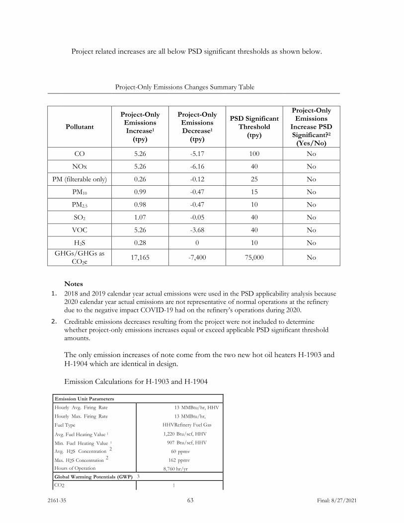
2161-35 63 Final: 8/27/2021
Project related increases are all below PSD significant thresholds as shown below.
Project-Only Emissions Changes Summary Table
Pollutant
Project-Only Emissions Increase1
(tpy)
Project-Only Emissions Decrease1
(tpy)
PSD Significant Threshold
(tpy)
Project-Only Emissions
Increase PSD Significant?2
(Yes/No) CO 5.26 -5.17 100 No
NOx 5.26 -6.16 40 No
PM (filterable only) 0.26 -0.12 25 No
PM10 0.99 -0.47 15 No
PM2.5 0.98 -0.47 10 No
SO2 1.07 -0.05 40 No
VOC 5.26 -3.68 40 No
H2S 0.28 0 10 No GHGs/GHGs as
CO2e 17,165 -7,400 75,000 No
Notes
1. 2018 and 2019 calendar year actual emissions were used in the PSD applicability analysis because 2020 calendar year actual emissions are not representative of normal operations at the refinery due to the negative impact COVID-19 had on the refinery’s operations during 2020.
2. Creditable emissions decreases resulting from the project were not included to determine whether project-only emissions increases equal or exceed applicable PSD significant threshold amounts. The only emission increases of note come from the two new hot oil heaters H-1903 and H-1904 which are identical in design. Emission Calculations for H-1903 and H-1904
Emission Unit Parameters
Hourly Avg. Firing Rate
Hourly Max. Firing Rate
Fuel Type
Avg. Fuel Heating Value 1
Min. Fuel Heating Value 1 Avg. H2S Concentration 2
Max. H2S Concentration 2 Hours of Operation
13 MMBtu/hr, HHV
13 MMBtu/hr,
HHV Refinery Fuel Gas
1,220 Btu/scf, HHV
907 Btu/scf, HHV
60 ppmv
162 ppmv
8,760 hr/yr Global Warming Potentials (GWP) 3
CO2 1

2161-35 64 Final: 8/27/2021
CH4 25 N2O 298
Pollutants Emission factor Hourly Avg. (lb/hr) Hourly Max. (lb/hr) Annual (tpy) Criteria Pollutants 4
PM (filterable) 0.0019 lb/MMBtu 0.02 0.02 0.11 PM10 {filterable+ condensable) 0.0075 lb/MMBtu 0.10 0.10 0.42 PM_ 2 5 (filterable+ condensable) 0.0075 lb/MMBtu 0.10 0.10 0.42 NOx 0.04 lb/MMBtu 0.52 0.52 2.28 voc 0.0054 lb/MMBtu 0.07 0.07 0.31 co 0.04 lb/MMBtu 0.52 0.52 2.28 SO2 - - 0.11 0.39 0.47
Greenhouse Gases 5 CO2 130.07 lb/MMBtu - - 7,406 CH4 0.0066 lb/MMBtu - - 0.38
N2O 0.0013 lb/MMBtu - - 0.08 CO2e - - - - 7,438
Notes: 1 Fuel heating value based on actual refinery fuel gas data (2015 calendar year data) determined to be a conservative representation of refinery fuel gas heating value for SO2 emission calculations.
2 NSPS Subpart Ja fuel gas H2S limitations (162 ppmv on a 3-hour rolling average basis and 60 ppmv on a 365 successive calendar day rolling average basis). 3 Values are EPA-designated global warming potential for specific greenhouse gases (40 CFR Part 98 Subpart A). 4 PM (filterable), PM10 , PM_ 2 5 , and VOC emission factors obtained from AP-42, Section 1.4, Table 1.4-2. Emission factors were corrected using typical natural gas heating value of 1,020 Btu/scf, as directed by footnote "a" of that table.
NOx and CO emission factors based on burner vendor specifications. SO2 emissions based on H2S concentration of refinery fuel gas and 100% conversion of H2S to SO2. 5 Emission factors obtained from 40 CFR Part 98 Subpart C, Tables C-1 and C-2 for fuel gas.
V. Existing Air Quality
As of July 8, 2002, Cascade County is designated as an Unclassifiable/Attainment area for all criteria pollutants.
VI. Ambient Air Impact Analysis
From a conventional pollutants standpoint, all emissions increases are expected to be nearly off-set by the decreases occurring from the heaters being shutdown. No discernable impact to ambient levels of NO2, CO, PM, SO2, or O3 would be expected.
VII. Taking or Damaging Implication Analysis
As required by 2-10-105, MCA, the Department conducted the following private property taking and damaging assessment.
YES NO X 1. Does the action pertain to land or water management or environmental regulation

2161-35 65 Final: 8/27/2021
YES NO affecting private real property or water rights?
X 2. Does the action result in either a permanent or indefinite physical occupation of private property?
X 3. Does the action deny a fundamental attribute of ownership? (ex.: right to exclude others, disposal of property)
X 4. Does the action deprive the owner of all economically viable uses of the property? X 5. Does the action require a property owner to dedicate a portion of property or to grant
an easement? [If no, go to (6)]. 5a. Is there a reasonable, specific connection between the government requirement and
legitimate state interests? 5b. Is the government requirement roughly proportional to the impact of the proposed use
of the property? X 6. Does the action have a severe impact on the value of the property? (consider economic
impact, investment-backed expectations, character of government action) X 7. Does the action damage the property by causing some physical disturbance with respect
to the property in excess of that sustained by the public generally? X 7a. Is the impact of government action direct, peculiar, and significant? X 7b. Has government action resulted in the property becoming practically inaccessible,
waterlogged or flooded? X 7c. Has government action lowered property values by more than 30% and necessitated the
physical taking of adjacent property or property across a public way from the property in question?
X Takings or damaging implications? (Taking or damaging implications exist if YES is checked in response to question 1 and also to any one or more of the following questions: 2, 3, 4, 6, 7a, 7b, 7c; or if NO is checked in response to questions 5a or 5b; the shaded areas)
Based on this analysis, the Department determined there are no taking or damaging implications associated with this permit action. VIII. Environmental Assessment
An environmental assessment, required by the Montana Environmental Policy Act, was completed for this project. A copy is attached.
2161-35 1 Final 8/27/2021
DEPARTMENT OF ENVIRONMENTAL QUALITY Air, Energy & Mining Division
Air Quality Bureau 1520 East Sixth Avenue
P.O. Box 200901 Helena, Montana 59620-0901
(406) 444-3490
ENVIRONMENTAL ASSESSMENT (EA) Issued For: Calumet Montana Refining, LLC (Calumet)
1900 10th Street North East Great Falls, MT 59404
Montana Air Quality Permit Number (MAQP): #2161-35 EA Draft: July 23, 2021 EA Final: August 11, 2021 Permit Final: August 27, 2021 1. Legal Description of Site: Calumet is located at 1900 10th Street N.E. in Great Falls, Montana.
The legal description of the site is the NE¼ of Section 1, Township 20 North, Range 3 East, Cascade County, Montana.
2. Description of Project: Installation of new equipment related to a modification in the polymer
modified asphalt (PMA) process and in the asphalt blending process. The project is identified as the Asphalt Upgrades Project.
3. Objectives of Project: To install new equipment to provide upgrades within the PMA process
and asphalt blending process to enhance facility profit. 4. Additional Project Site Information: This refinery has operated at this site since the 1930’s. The
refinery currently employs approximately 186 people, and is located along the Missouri River in Great Falls, Montana.
5. Alternatives Considered: In addition to the proposed action, the Department considered the
"no-action" alternative. The "no-action" alternative would deny issuance of the air quality preconstruction permit to the proposed facility. However, the Department does not consider the "no-action" alternative to be appropriate because Calumet seeks to comply with all applicable rules and regulations as required for permit issuance. Therefore, the "no-action" alternative was eliminated from further consideration.
6. A Listing of Mitigation, Stipulations, and Other Controls: A listing of the enforceable permit
conditions and a permit analysis would be contained in MAQP #2161-35. 7. Regulatory Effects on Private Property Rights: The Department considered alternatives to the
conditions imposed in this permit as part of the permit development. The Department determined the permit conditions would be reasonably necessary to ensure compliance with applicable requirements and to demonstrate compliance with those requirements and would not unduly restrict private property rights.
2161-35 2 Final 8/27/2021
8. SUMMARY OF COMMENTS ON POTENTIAL PHYSICAL AND BIOLOGICAL
EFFECTS: The following comments have been prepared by the Department.
A. Terrestrial and Aquatic Life and Habitats
MAQP #2161-35 would authorize the construction and operation of a modified PMA process and asphalt blending process. Emission increases associated with the proposed project are below PSD significant emission increase levels. The project is in an area of current industrial operations. The level of emissions presented would not be expected to cause any discernable impact to terrestrial and aquatic life and habitats.
B. Water Quality, Quantity, and Distribution
MAQP #2161-35 would authorize the construction and operation of a modified PMA process and asphalt blending process. Emission increases associated with the proposed project are below significant emission increase levels. The level of emissions presented would not be expected to cause any discernable impact to water quality. The project would be located in an area of current industrial operations. MAQP #2161-35 would authorize emissions at a level which would not be expected to result in any significant impact to water quality, quantity, or distribution.
C. Geology and Soil Quality, Stability, and Moisture
MAQP #2161-35 would authorize the construction and operation of an electric catalytic thermal oxidizer to destroy volatile organic compounds recovered from remediation of hydrocarbon contamination. The level of emissions presented would not be expected to cause any discernable impacts.
D. Vegetation Cover, Quantity, and Quality
MAQP #2161-35 would authorize the construction and operation of a modified PMA process and asphalt blending process. Emission increases associated with the proposed project are below significant emission increase levels. The level of emissions presented would not be expected to cause any discernable impact to vegetation cover, quantity, and quality.
E. Aesthetics
Construction activities and associated equipment will generate minor levels of noise. The new equipment installed for the project would not be expected to markedly change the overall noise level from the property. The project would occur on land already used for industrial activities.
F. Air Quality
No discernable impact to conventional pollutant air quality would be expected.
G. Unique Endangered, Fragile, or Limited Environmental Resources
2161-35 3 Final 8/27/2021
The project takes place within an already developed, industrial area. No significant impacts to unique endangered, fragile, or limited environmental resources would be expected.
H. Sage Grouse Executive Order
The Department recognizes that the site location is not within a Greater Sage Grouse Habitat Area as defined by Executive Order No. 12-2015.
I. Demands on Environmental Resources of Water, Air, and Energy
No significant impacts to water, air, or energy would be expected.
J. Historical and Archaeological Sites
No significant impacts to historical or archaeological sites would be expected as no known historical or archaeological sites exist in the immediate area.
K. Cumulative and Secondary Impacts
No significant impacts to any of the individual physical and biological considerations above were found. No significant cumulative or secondary impacts would be expected. The project seeks to remediate a contaminated site.
9. SUMMARY OF COMMENTS ON POTENTIAL ECONOMIC AND SOCIAL EFFECTS:
The following comments have been prepared by the Department.
A. Social Structures and Mores, and B. Cultural Uniqueness and Diversity
No increase in the number of people employed at the site is expected as a result of the project. Temporary construction activities would take place. The area is a currently developed industrial site. No more than a minor impact to social structures and mores would be expected.
C. Local and State Tax Base and Tax Revenue
The project provides numerous changes within the PMA process and asphalt blending process. No significant impact to local and state tax base and revenue would be expected.
D. Agricultural or Industrial Production
The project would take place within an industrial area. Emissions are expected to be minor. Minor, if any, impacts to industrial or agricultural production would be expected.
E. Human Health
The emissions from the Asphalt Upgrades Project are minor and no discernable change in ambient air is expected.
F. Access to and Quality of Recreational and Wilderness Activities

2161-35 4 Final 8/27/2021
Emissions are expected to be minor. No more than minor impacts to access to and quality of recreational and wilderness activities would be expected.
G. Quantity and Distribution of Employment
No increase in the number of people employed at the site would be expected as a result of the project. Temporary construction activities would take place.
H. Distribution of Population
No increase in the number of people employed at the site is expected as a result of the project. Temporary construction activities will take place.
I. Demands of Government Services
Various permits and compliance monitoring of the terms and conditions of the permits would be required. No significant demand is expected.
J. Industrial and Commercial Activity
The area is currently an active industrial site. Temporary construction activities would be required.
K. Locally Adopted Environmental Plans and Goals
The Department is not aware of significant impacts to any locally adopted environmental plans or goals.
L. Cumulative and Secondary Impacts
No significant impacts to any of the individual physical and biological considerations above were found. No significant cumulative or secondary impacts would be expected. The project seeks to remediate a contaminated site.
Recommendation: An Environmental Impact Statement (EIS) is not required. If an EIS is not required, explain why the EA is an appropriate level of analysis: All potential effects resulting from construction and operation of the proposed facility are not determined significant or potentially significant; therefore, an EIS is not required. Other groups or agencies contacted or which may have overlapping jurisdiction: Montana Department of Environmental Quality Waste Management and Remediation Division; Montana Natural Heritage Program; and the State Historic Preservation Office (Montana Historical Society). Individuals or groups contributing to this EA: Montana Department of Environmental Quality (Air Quality Bureau), Montana State Historic Preservation Office (Montana Historical Society). EA prepared by: Craig Henrikson Date: 7/20/2021