cairo metro project e14155 - presentation to jv 23 dec 2014
TRANSCRIPT
1 December 2014

2
Contents
• First Depot design and construction item• Number of Design Stages• Design Delivery Schedule• Design Phase 4A/4b Boundary Limits for Groups G1 to G6
• Comparative Structural designs
3
FIRST DEPOT DESIGN AND CONSTRUCTION ITEM
4
First Depot design and construction• After site clearance, the first design and construction item for the depot, will be an equipment low point and inspection trench drainage design.
• This will be from the lowest points in the depot, the bogie drop and the wheel grinding lathe, plus all of the inspection trenches in the various buildings.
• There will possibly need to be a low point sump and pump for this drainage to sewer.
• There will be separate shallower stormwater (if required) or sanitary drainage systems.

5
Where has the bogie drop gone to?

6
NUMBER OF DESIGN STAGES
7
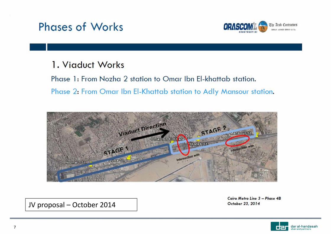
JV proposal – October 2014
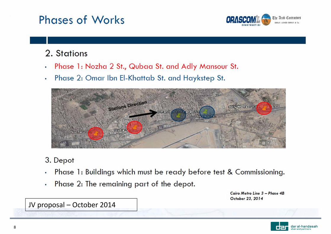
8
JV proposal – October 2014
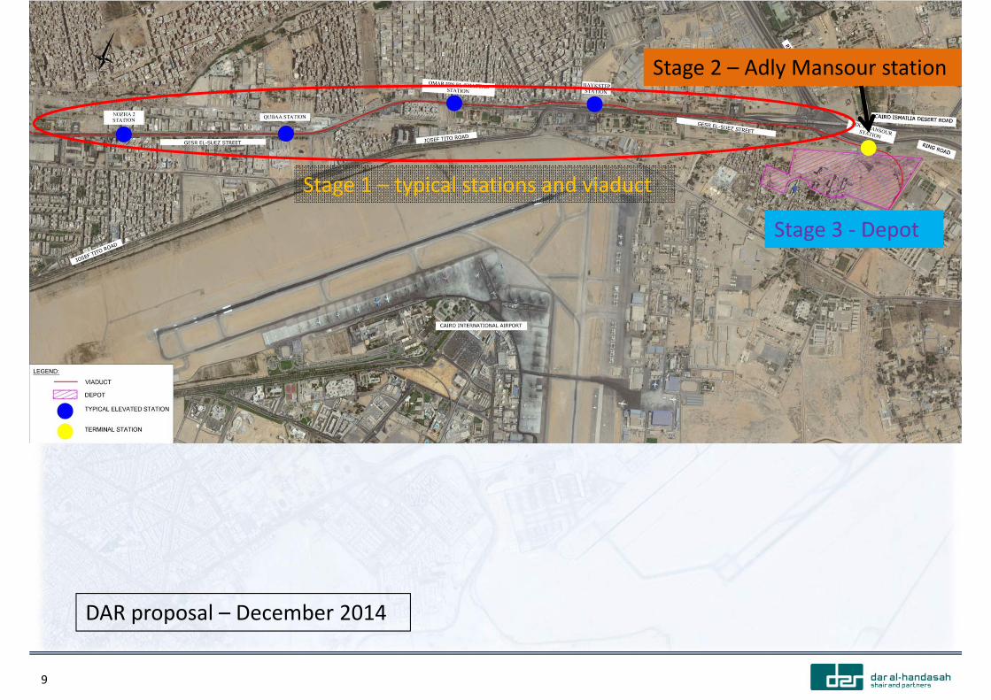
9
Stage 1 – typical stations and viaduct
Stage 2 – Adly Mansour station
Stage 3 ‐ Depot
DAR proposal – December 2014

10
Which Depot buildings need to be ready for test and commissioning?
11
DESIGN DELIVERY SCHEDULE
12
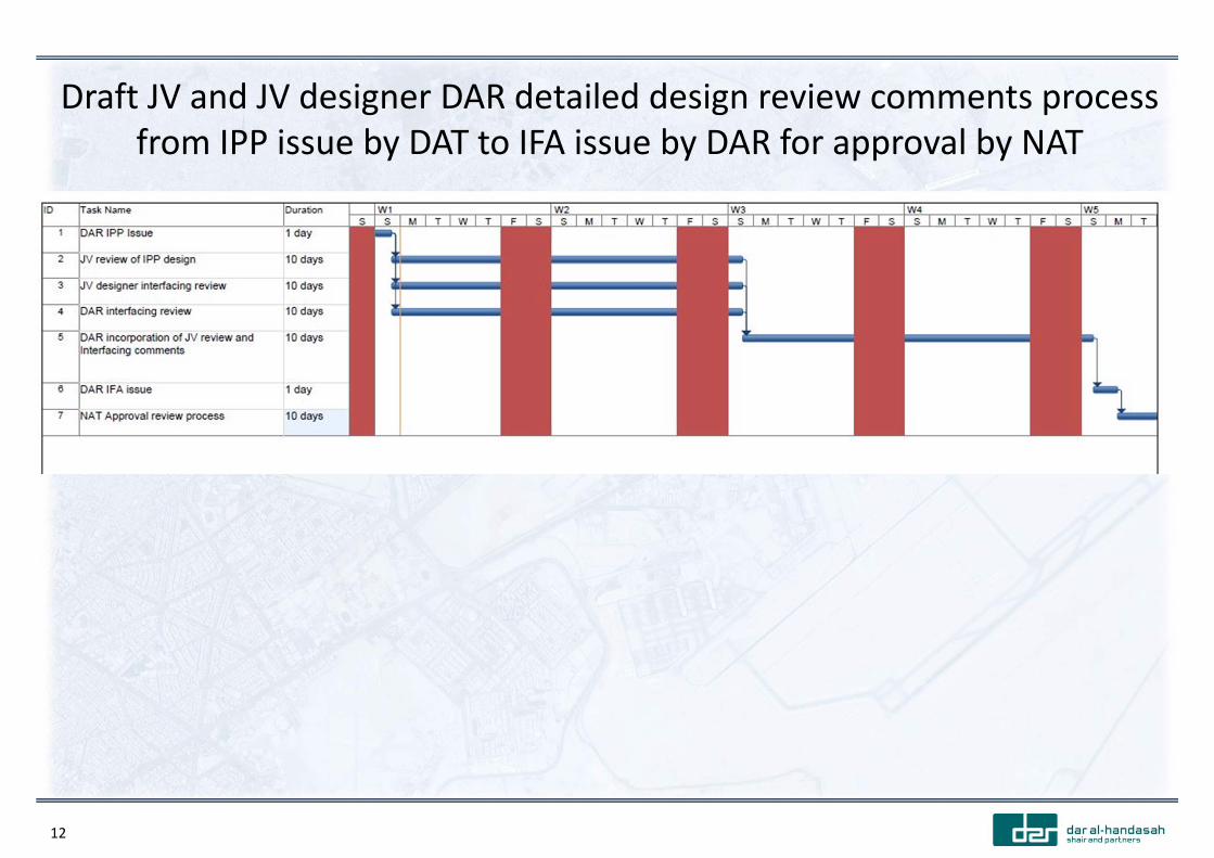
Draft JV and JV designer DAR detailed design review comments process from IPP issue by DAT to IFA issue by DAR for approval by NAT
13
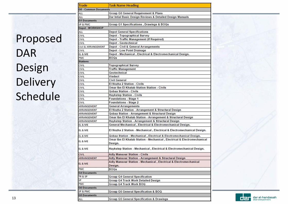
Proposed DAR Design Delivery Schedule
14
DESIGN PHASE 4A/4B BOUNDARY LIMITS FOR GROUPS G1 TO G6

15
Group 2 – Civil and Structural Engineering with station and viaduct architectural (arrangement), electrical, plumbing and fire fightingGroup 3 – Power Supply, Electromechanical and Mechanical with depot (workshop) architectural (arrangement), electrical, plumbing and fire fightingGroup 6 ‐ Toll (ticketing) Equipment Red text design and installation items by Phase 4a in a Phase 4b station
El Nozha 2 Station
16
COMPARATIVE STRUCTURAL DESIGNS –based on current information only

17
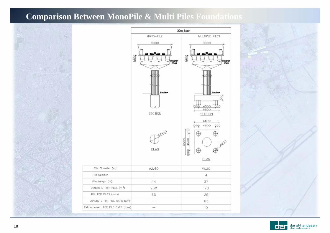
Geotechnical comments on pile foundationsDisadvantages of using Mono‐piles (2.4m diameter) in lieu of a group of 1.2m diameter piles to support the columns of viaduct and stations:
• Reduction of allowable concrete pile structural carrying capacity
• Reduction of allowable concrete pile geotechnical carrying capacity by about 25%
• Tolerance of deviation of pile centerline should not exceed 0.1 of the equivalent pile diameter and its effect if any should be considered in pile/ pile cap design.
• Pile load tests frequency should be 1 test for each 50 piles.
• More costly load testing configuration for both preliminary and working piles
• Nondestructive tests should be performed on all Mono‐piles.
• Strict precautions should be taken during construction.
• Limited previous local experience with construction of 2.4m diameter piles
• Costly remedial solutions in case of non acceptance of mono‐pile after its construction
18
Comparison Between MonoPile & Multi Piles Foundations
19
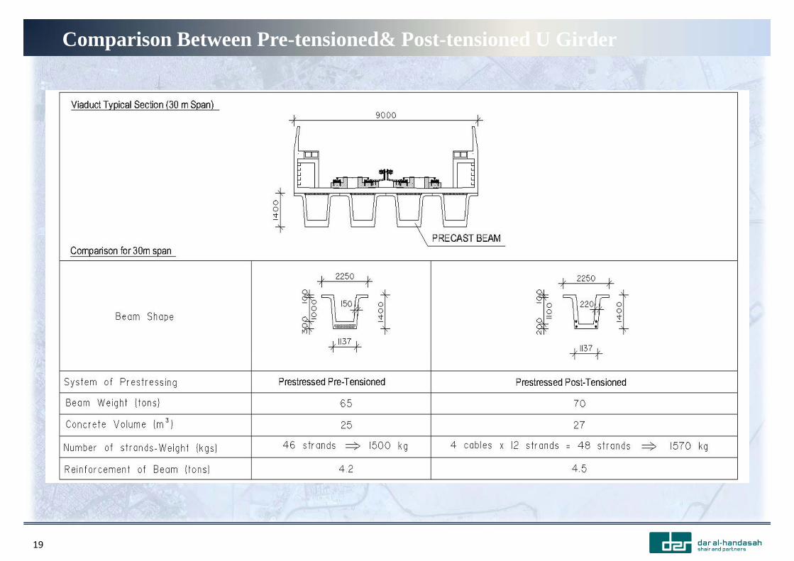
Comparison Between Pre-tensioned& Post-tensioned U Girder
20
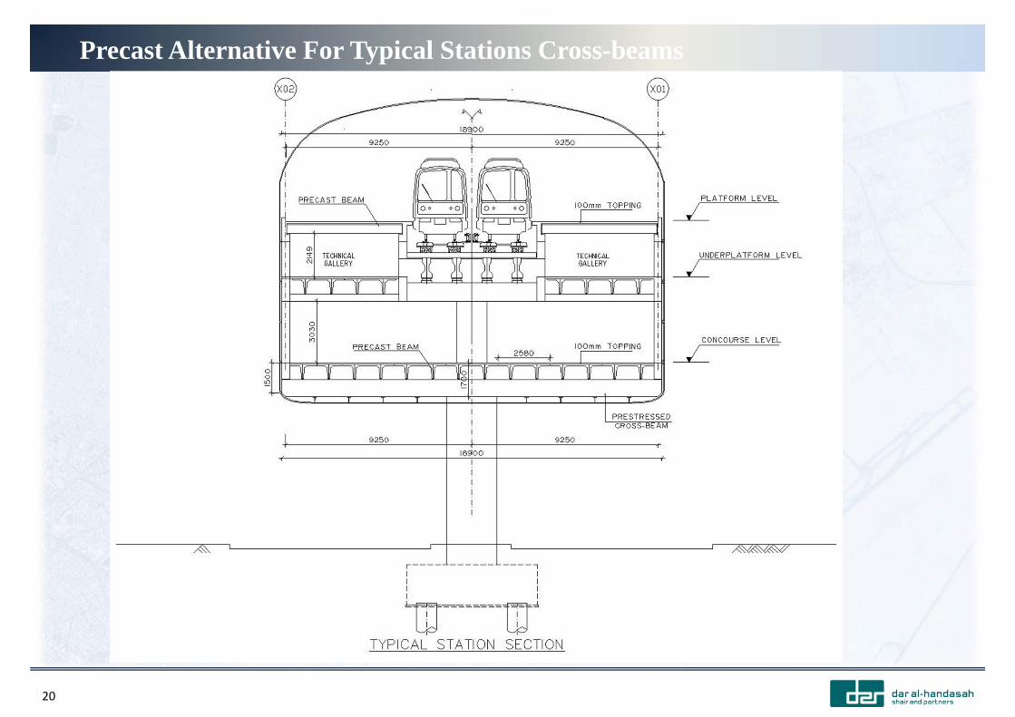
Precast Alternative For Typical Stations Cross-beams

21
Precast Alternative For Typical Stations Cross-beams

22
Precast Alternative For Typical Stations Cross-beams

23
Precast Alternative For Typical Stations Cross-beams
24
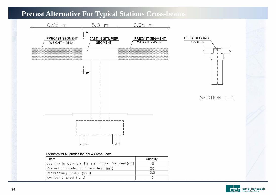
Precast Alternative For Typical Stations Cross-beams
25
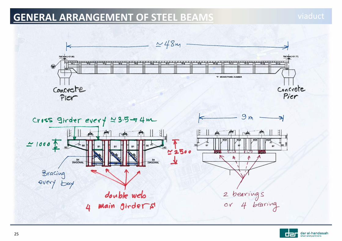
GENERAL ARRANGEMENT OF STEEL BEAMS viaduct

26
STEEL BEAMS PROFILES viaduct

27
OPTION‐I OF CONSTRUCTION viaduct
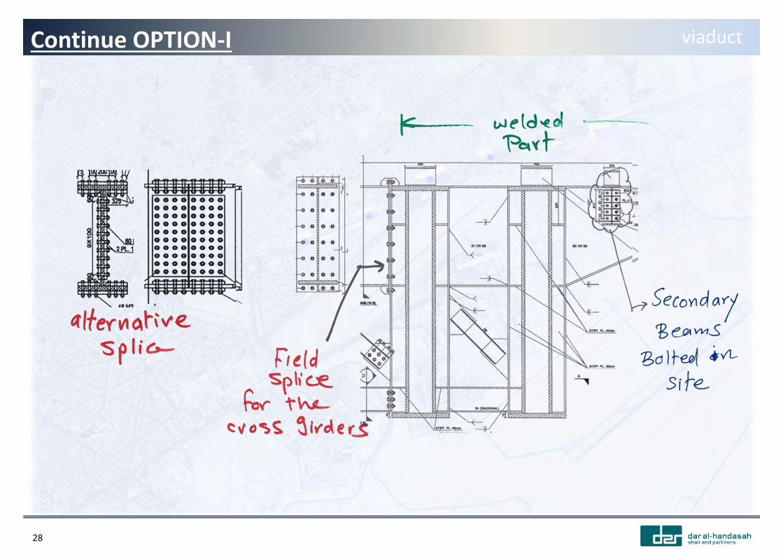
28
Continue OPTION‐I viaduct
29
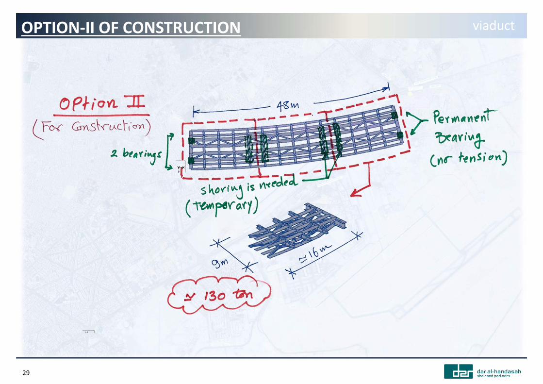
OPTION‐II OF CONSTRUCTION viaduct

30
Continue OPTION‐II viaduct
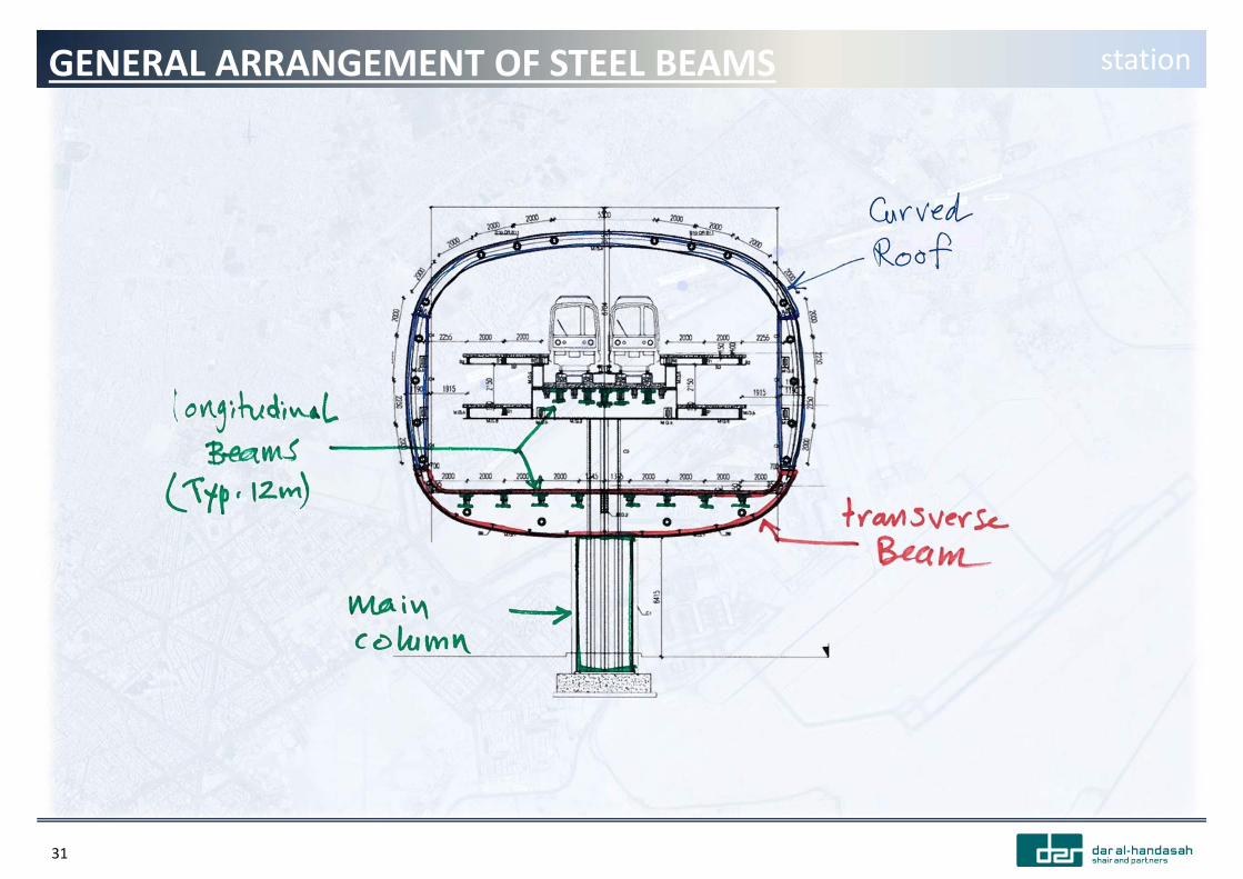
31
GENERAL ARRANGEMENT OF STEEL BEAMS station
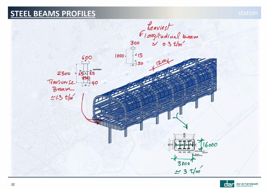
32
STEEL BEAMS PROFILES station
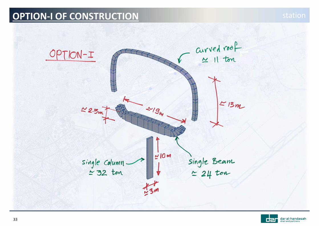
33
OPTION‐I OF CONSTRUCTION station
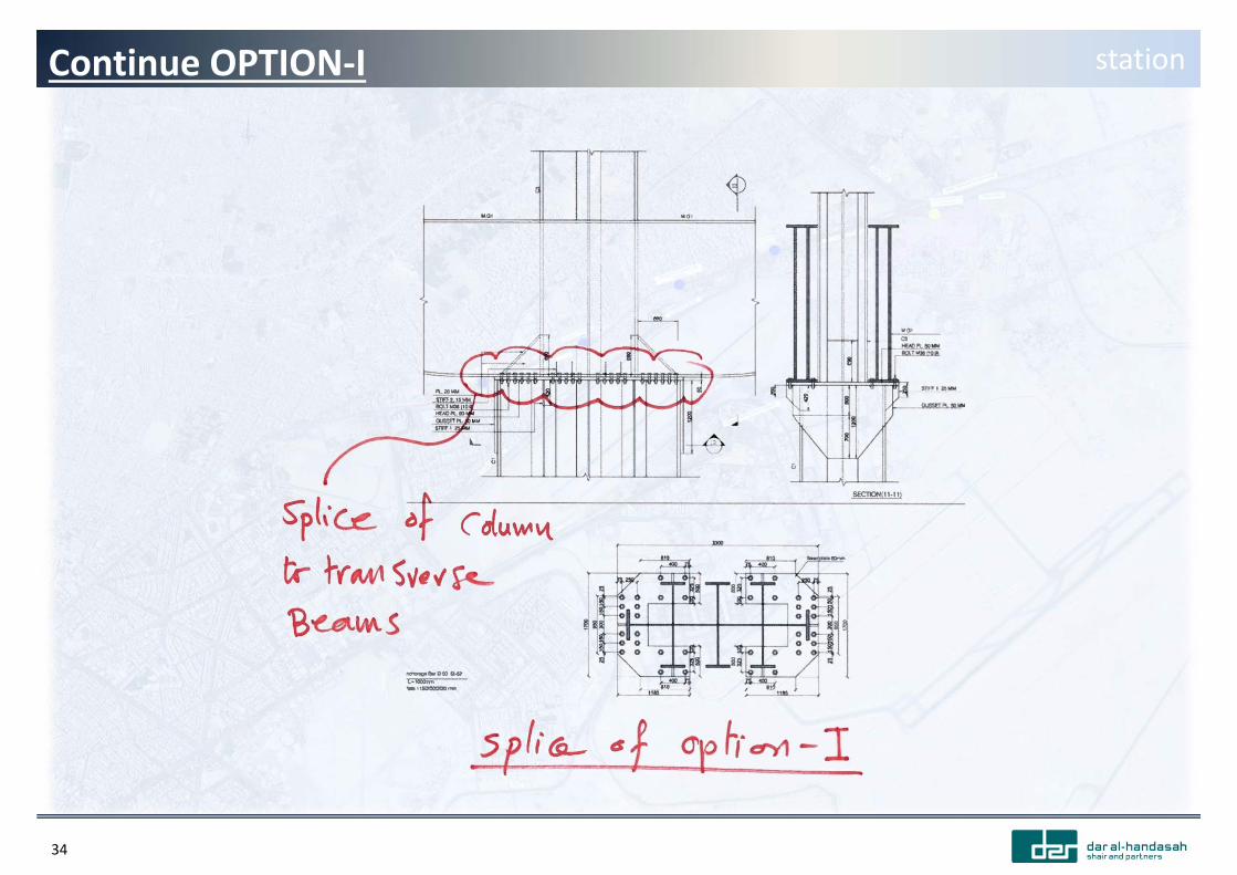
34
Continue OPTION‐I station
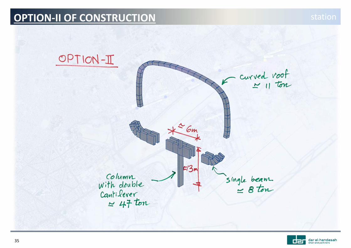
35
OPTION‐II OF CONSTRUCTION station
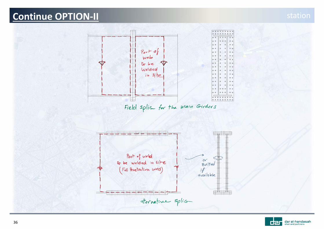
36
Continue OPTION‐II station