bulletin 140u molded case circuit breaker with...
TRANSCRIPT

Bulletin 140U Molded Case Circuit Breakers withInstantaneous Maintenance Mode Setting (IMM)
Assisting in Reducing Arc Flash Energy
Rockwell Automation introduces Molded Case Circuit Breakers (MCCBs)
with Instantaneous Maintenance Mode (IMM) settings. These MCCBs
with IMM allow users another tool in mitigating the damage associated
with Arc Flash in industrial control panels and motor control centers. The
IMM provides a separate maintenance mode which can be set to trip the
breaker at currents from 2.5 to 4 times the breaker rating. This provides
reduced response time to Arcing faults when compared to normal MCCBs
adjusted for maximum coordination or to fuses.
In testing done comparing the performance of fuses, MCCBs and MCCBs
with IMM enabled under simulated Arcing fault conditions, the IMM
functionality showed a measurable reduction in the Arc energy allowed.
In testing using the Arcing fault test as defi ned under IEEE 1584 tests the
results as shown above were obtained simulating an Arcing fault of
9800 A rms at 480V.
Features and Benefi ts
Faster Reaction to Arcing Faults
• Allows less energy under arcing
fault conditions
• Results in less potential damage
IMM Can Be Remotely Engaged
• Allows maintenance personnel to
enable the protection wearing PPE
suitable for the lower energy level
• Results in more productivity
by not having to fully suit up
(in some applications)
IMM Off ers Second Instantaneous
Trip Settings
• Provides the ability to adjust the
breaker for maintenance conditions
• Provides improved Arc mitigation
while adjustability reduces
nuisance tripping
Multiple Confi rmations Provided
from the Module
• Pilot light and separate hard
contact provided
• Provides additional confi rmation
that unit is in maintenance mode
both locally and/or through another
output device
Test – 1200 A Fuse
Brand L-class
1200 A fuses
Result – Fuse tripped at
771 ms, 15.7 kA peak
17.89 calories/cm2
Test – 1200 A MCCB
with IMM
Maintenance Mode
enabled, IR = 1220 A,
Maintenance Mode ON
Result – Breaker tripped
at 18.7 ms, 16.8 kA peak
0.71 calories/cm2
1200 A Fuse vs 1200 Molded Case Circuit Breaker with IMM
Allen-Bradley Parts
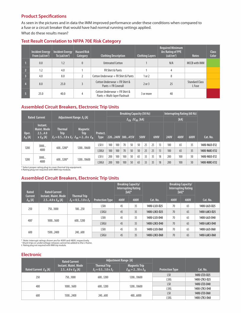
Product Specifi cations
As seen in the pictures and in data the IMM improved performance under these conditions when compared to
a fuse or a circuit breaker that would have had normal running settings applied.
What do these results mean?
Test Result Correlation to NFPA 70E Risk Category
Incident Energy From (cal/cm2)
Incident Energy To (cal/cm2)
Hazard Risk Category Clothing Description Clothing Layers
Required Minimum Arc Rating of PPE
(cal/cm2) NotesClass Color
1 0.0 1.2 0 Untreated Cotton 1 N/A MCCB with IMM
2 1.2 4.0 1 FR Shirt & Pants 1 4
3 4.0 8.0 2 Cotton Underwear + FR Shirt & Pants 1 or 2 8
4 8.0 25.0 3Cotton Underwear + FR Shirt &
Pants + FR Coverall2 or 3 25
Standard Class L Fuse
5 25.0 40.0 4Cotton Underwear + FR Shirt &
Pants + Multi-layer Flashsuit3 or more 40
Rated Current Adjustment Range Ir [A]Breaking Capacity (50 Hz) Interrupting Rating (60 Hz)
Cat. No.
Icu IIos [kA] [kA]
Oper.In [A]
Instant.Maint. Mode
2.5...4.0x In [A]
ThermalTrip
Ir = 0.5...1.0 x Ir
MagneticTrip
Im = 2...8 x In
Protect.Type 220...240V 380...415V 500V 690V 240V 480V 600V
12003000...4800
600...1200* 1200...10600LSII ‡ 100 100 70 50 50 25 25 13 100 65 35 140U-N6J3-E12
LSIIG‡ 100 100 70 50 50 25 25 13 100 65 35 140U-N6K3-E12
12003000...4800
600...1200* 1200...10600LSII ‡ 200 100 100 50 65 33 35 18 200 100 50 140U-N0J3-E12
LSIIG‡ 200 100 100 50 65 33 35 18 200 100 50 140U-N0K3-E12
Rated Current In [A]
Rated Current Instant. Maint. Mode
2.5...4.0 x In [A]
Adjustment Range [A]
Protection Type Cat. No. Thermal Trip
Ir = 0.5...1.0 x Ir
Magnetic TripIm = 2...10 x In
250 750...1000 600...1200 1200...10600LSII 140U-LTJ3-D25
LSIIG 140U-LTK3-D25
400 1000...1600 600...1200 1200...10600LSII 140U-LTJ3-D40
LSIIG 140U-LTK3-D40
600 1500...2400 240...600 480...6000LSII 140U-LTJ3-D60
LSIIG 140U-LTK3-D60
Rated Current In [A]
Rated Current Instant. Maint. Mode
2.5...4.0 x In [A]Thermal Trip
Ir = 0.5...1.0 x Ir Protection Type
Breaking Capacity/Interrupting Rating
[kA]*
Cat. No.
Breaking Capacity/Interrupting Rating
[kA]*
Cat. No. 400V 480V 400V 480V
250 750...1000 100...250LSII‡ 45 35 140U-L3J3-D25 70 65 140U-L6J3-D25
LSIIG‡ 45 35 140U-L3K3-D25 70 65 140U-L6K3-D25
4001 1000...1600 600...1200LSII‡ 45 35 140U-L3J3-D40 70 65 140U-L6J3-D40
LSIIG‡ 45 35 140U-L3K3-D40 70 65 140U-L6K3-D40
600 1500...2400 240...600LSII‡ 45 35 140U-L3J3-D60 70 65 140U-L6J3-D60
LSIIG‡ 45 35 140U-L3K3-D60 70 65 140U-L6K3-D60
* Select proper rating plug to cover thermal trip equipment.‡ Rating plug not required with IMM trip module.
* Note: interrupt ratings shown are for 400V and 480V, respectively. 1 Shunt trips or undervoltage releases cannot be added to the L-frame.‡ Rating plug not required with IMM trip module.
Assembled Circuit Breakers, Electronic Trip Units
Assembled Circuit Breakers, Electronic Trip Units
Electronic

Rockwell Automation is a trademark of Rockwell Automation, Inc. Trademarks not belonging to Rockwell Automation are property of their respective companies.
Publication 140U-PP009A-EN-P – July 2011 Copyright © 2011 Rockwell Automation, Inc. All Rights Reserved. Printed in USA.
A second instantaneous trip setting is used in
maintenance mode. When IMM is enabled the breaker
can be adjusted to trip at 2.5 to 4 times the breaker rating.
In IMM the standard Instantaneous settings are bypassed
and a special analog circuit trips the breaker in 30 msec or
less when sensed current exceeds the setting current.
Additionally, when set, a blue indicator appears in the
setting window next to the setting dial. When enabled,
a blue LED illuminates on the front of the breaker and
provides visual indication at the MCCB that the breaker is
now in maintenance mode.
In addition to the LED indication a dedicated contact within the breaker closes to allow an external indication the MCCB is in Maintenance Mode.
Wiring the L Frame IMM module.
Setting the IMM
Allen-Bradley Parts