100a/60a universal voltage gmt fuse panels with … universal voltage gmt fuse panels ... and fuse...
TRANSCRIPT

100A/60A Universal Voltage GMT Fuse Panels
With Enhanced Power/Fuse & Bay AlarmsPower :: HPGMTXX & GMTXX
© Telect, Inc., All Rights Reserved, 132152-9 A01.509.926.6000 :: telect.com
Applies to : GMT10 :: GMT10FA :: GMT20 :: GMT20S :: HPGMT10 :: HPGMT10FA :: HPGMT15 :: HPGMT20 :: HPGMT20S
Installation Guide
© Telect, Inc., All Rights Reserved, 132152-10 A01.509.926.6000 :: telect.com
ii
100A/60A Universal Voltage GMT Fuse Panels
With Enhanced Power/Fuse & Bay AlarmsPower :: HPGMTXX & GMTXX
Table of Contents
1.1 Overview .........................................................................................................................11.2 Specifi cations ..................................................................................................................31.3 Important Installation Guidelines .....................................................................................51.4 Inspection ........................................................................................................................61.5 Installation .......................................................................................................................61.6 Accessories & Alarm Card ............................................................................................. 13
1.5.1 Input & GND Lugs ................................................................................................. 131.5.2 Single-hole Lug Part Numbers for GMT20 Output Terminals ................................ 141.5.3 GMT Fuses ........................................................................................................... 141.5.4 Alarm Card ............................................................................................................ 15
1.7 Diagrams ....................................................................................................................... 151.8 Dimensions .................................................................................................................... 17
List of FiguresFigure 1 - GMT Fuse Panel ...................................................................................................1Figure 2 - GMT-Series Comparison Chart ............................................................................2Figure 3 - Bracket Orientation ...............................................................................................7Figure 4 - Rack Mounting ......................................................................................................7Figure 5 - Ground Lug Connection........................................................................................8Figure 6 - Input Connections on a 100A Panel .....................................................................9Figure 7 - Input Connections on a 60A Panel .......................................................................9Figure 8 - Status LEDs on Face of ..................................................................................... 10Figure 9 - Alarm Terminals on Rear of Panel ...................................................................... 10Figure 10 - Output Connections .......................................................................................... 10Figure 11 - Designation Card .............................................................................................. 11Figure 12 - Alarm Schematics (Rear of Designation Card) ................................................. 12Figure 13 - Alarm Card ........................................................................................................ 15Figure 14 - GMT10 & GMT10FA ......................................................................................... 15Figure 15 - HPGMT10 & HPGMT10FA ............................................................................... 16Figure 16 - GMT20S (Typical dimensions also for GMT20) ................................................ 17Figure 17 - HPGMT10 (Typical dimensions also for GMT10, HPGMT15, & HPGMT20S) .. 18Figure 18 - HPGMT20 ......................................................................................................... 19Figure 19 - HPGMT10FA .....................................................................................................20Figure 20 - GMT10FA .........................................................................................................21

© Telect, Inc., All Rights Reserved, 132152-10 A01.509.926.6000 :: telect.com
1
100A/60A Universal Voltage GMT Fuse Panels
With Enhanced Power/Fuse & Bay AlarmsPower :: HPGMTXX & GMTXX
1.1 Overview
Telect’s 60A and 100A GMT Panels arecompact 1RU EIA power panels enabling+ 24 and -48 Vdc power protection for avariety of wireline and wirelesstelecommunications and data equipment.These GMT-Series panels are ideal forpowering tracer lamps in dense DSXbays, as well as network equipment withlow-to-medium power requirements.Most GMT-Series panels fi t either 19-in. or 23-in. racks. (See the comparison chart on page 2.) All panels are white except HPGMT10-BLK, which is black.
The panel provides total front access to fuses and LED status. Below the bezel holding the status LEDs is a pull-out designation card holder.
All terminals for inputs, outputs, ground, and alarms are on the same side — either all on the rear or all on the front. All terminals are covered by a single full-width transparent terminal cover:
• Inputs are either dual-hole lugs for studs (100A panels) or bare conductors for barrel connectors (60A panels).
• Ground terminals accept either single- or dual-hole lugs.
• Output screw-post terminals accept either ring or forked lugs, as well as bare wire.
• Power/fuse and bay alarms terminals, along with external bay alarm trigger terminals, are wirewrap pins.
GMT-Series panels differ in load rating (60A or 100A), capacity (10, 15, or 20 GMTs per side), single or dual feed, and total front access (GMT10FA and HPGMT10FA) panels vs. panels with rear-side terminals. All panels are 1RU with the exception of HPGMT10FA, which is 2RU.
The GMT fuse holders are mounted upside-down so that the GMT indicator fl ag fl ips downward when activated, making identifi cation and detection easier, especially on tall racks. In addition, the GMT fuse holders are mounted separately — not as a fuse block — thereby making fuse- position management unnecessary when dealing with 10A, 15A, and 20A GMT fuses. Holes for color-coded fuse designation pins are located below each fuse position.
The panel also features separate power and fuse failure status LEDs and power alarm relay connections for each feed. Major and minor bay alarm LEDs and wirewrap terminals are controlled via an on-board relay triggered by an external switch closure. All on-board relay contacts are dry Form-C. All LEDs and alarm relays and contacts are located on an easily removable alarm card.
Figure 1 - GMT Fuse Panel
© Telect, Inc., All Rights Reserved, 132152-10 A01.509.926.6000 :: telect.com
2
100A/60A Universal Voltage GMT Fuse Panels
With Enhanced Power/Fuse & Bay AlarmsPower :: HPGMTXX & GMTXX
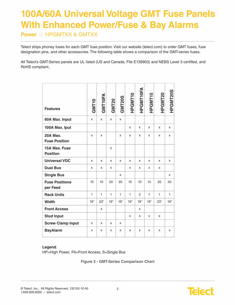
Telect ships phoney fuses for each GMT fuse position. Visit our website (telect.com) to order GMT fuses, fuse designation pins, and other accessories. The following table shows a comparison of the GMT-series fuses.
All Telect’s GMT-Series panels are UL listed (US and Canada, File E139903) and NEBS Level 3 certifi ed, and RoHS compliant.
Features
60A Max. Input x x x x
100A Max. Iput x x x x x
20A Max.
Fuse Position
x x x x x x x x
15A Max. Fuse
Position
x
Universal VDC x x x x x x x x x
Dual Bus x x x x x x x
Single Bus x x
Fuse Positions
per Feed
10 10 20 20 10 10 15 20 20
Rack Units 1 1 1 1 1 2 1 1 1
Width 19” 23” 19” 19” 19” 19” 19” 23” 19”
Front Access x x
Stud Input x x x x
Screw Clamp Input x x x x
BayAlarm x x x x x x x x x
GM
T10
GM
T10
FA
GM
T2
0
GM
T2
0S
HP
GM
T10
HP
GM
T10
FA
HP
GM
T15
HP
GM
T2
0S
HP
GM
T2
0
Legend:HP=High Power, FA=Front Access, S=Single Bus
Figure 2 - GMT-Series Comparison Chart
© Telect, Inc., All Rights Reserved, 132152-10 A01.509.926.6000 :: telect.com
3
100A/60A Universal Voltage GMT Fuse Panels
With Enhanced Power/Fuse & Bay AlarmsPower :: HPGMTXX & GMTXX
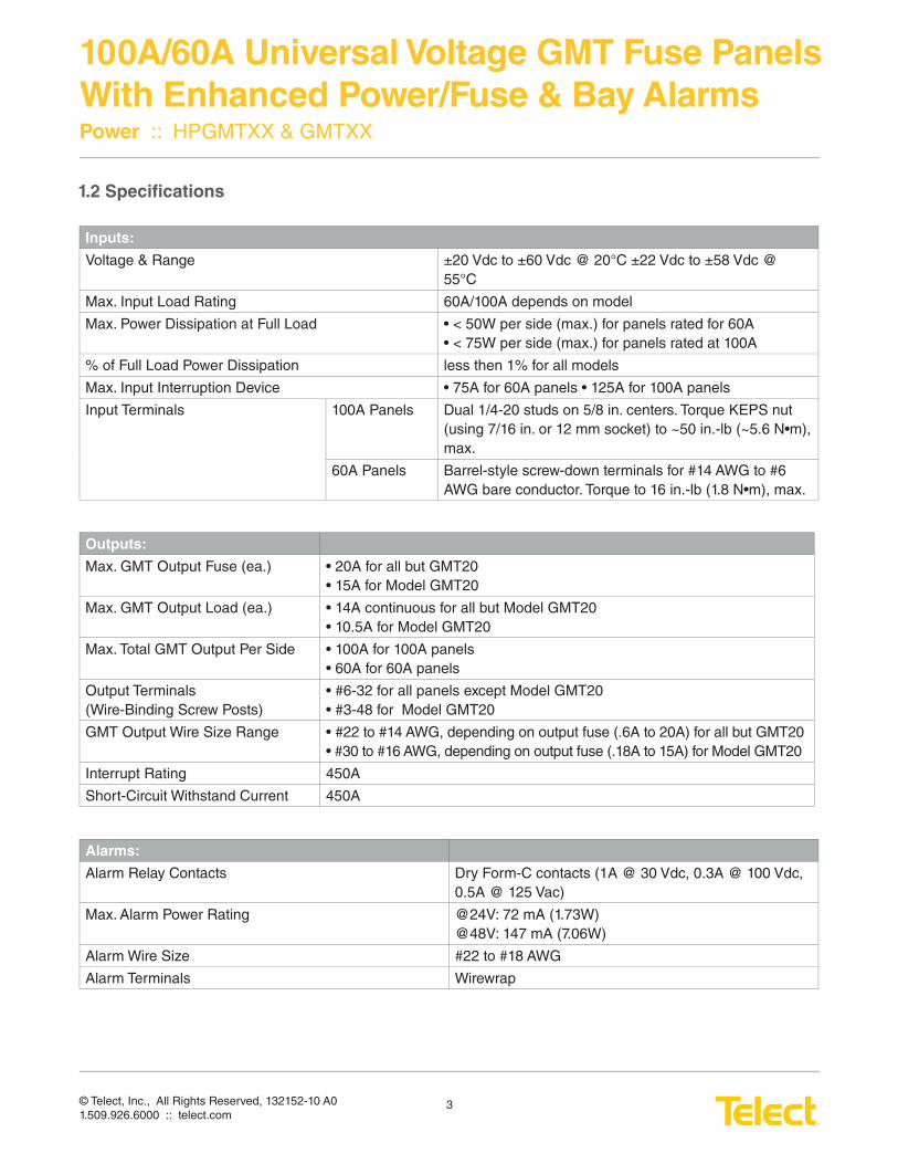
1.2 Specifi cations
Inputs:
Voltage & Range ±20 Vdc to ±60 Vdc @ 20°C ±22 Vdc to ±58 Vdc @ 55°C
Max. Input Load Rating 60A/100A depends on model
Max. Power Dissipation at Full Load • < 50W per side (max.) for panels rated for 60A • < 75W per side (max.) for panels rated at 100A
% of Full Load Power Dissipation less then 1% for all models
Max. Input Interruption Device • 75A for 60A panels • 125A for 100A panels
Input Terminals 100A Panels Dual 1/4-20 studs on 5/8 in. centers. Torque KEPS nut (using 7/16 in. or 12 mm socket) to ~50 in.-lb (~5.6 N•m), max.
60A Panels Barrel-style screw-down terminals for #14 AWG to #6 AWG bare conductor. Torque to 16 in.-lb (1.8 N•m), max.
Outputs:
Max. GMT Output Fuse (ea.) • 20A for all but GMT20 • 15A for Model GMT20
Max. GMT Output Load (ea.) • 14A continuous for all but Model GMT20 • 10.5A for Model GMT20
Max. Total GMT Output Per Side • 100A for 100A panels • 60A for 60A panels
Output Terminals(Wire-Binding Screw Posts)
• #6-32 for all panels except Model GMT20 • #3-48 for Model GMT20
GMT Output Wire Size Range • #22 to #14 AWG, depending on output fuse (.6A to 20A) for all but GMT20• #30 to #16 AWG, depending on output fuse (.18A to 15A) for Model GMT20
Interrupt Rating 450A
Short-Circuit Withstand Current 450A
Alarms:
Alarm Relay Contacts Dry Form-C contacts (1A @ 30 Vdc, 0.3A @ 100 Vdc, 0.5A @ 125 Vac)
Max. Alarm Power Rating @24V: 72 mA (1.73W) @48V: 147 mA (7.06W)
Alarm Wire Size #22 to #18 AWG
Alarm Terminals Wirewrap
© Telect, Inc., All Rights Reserved, 132152-10 A01.509.926.6000 :: telect.com
4
100A/60A Universal Voltage GMT Fuse Panels
With Enhanced Power/Fuse & Bay AlarmsPower :: HPGMTXX & GMTXX
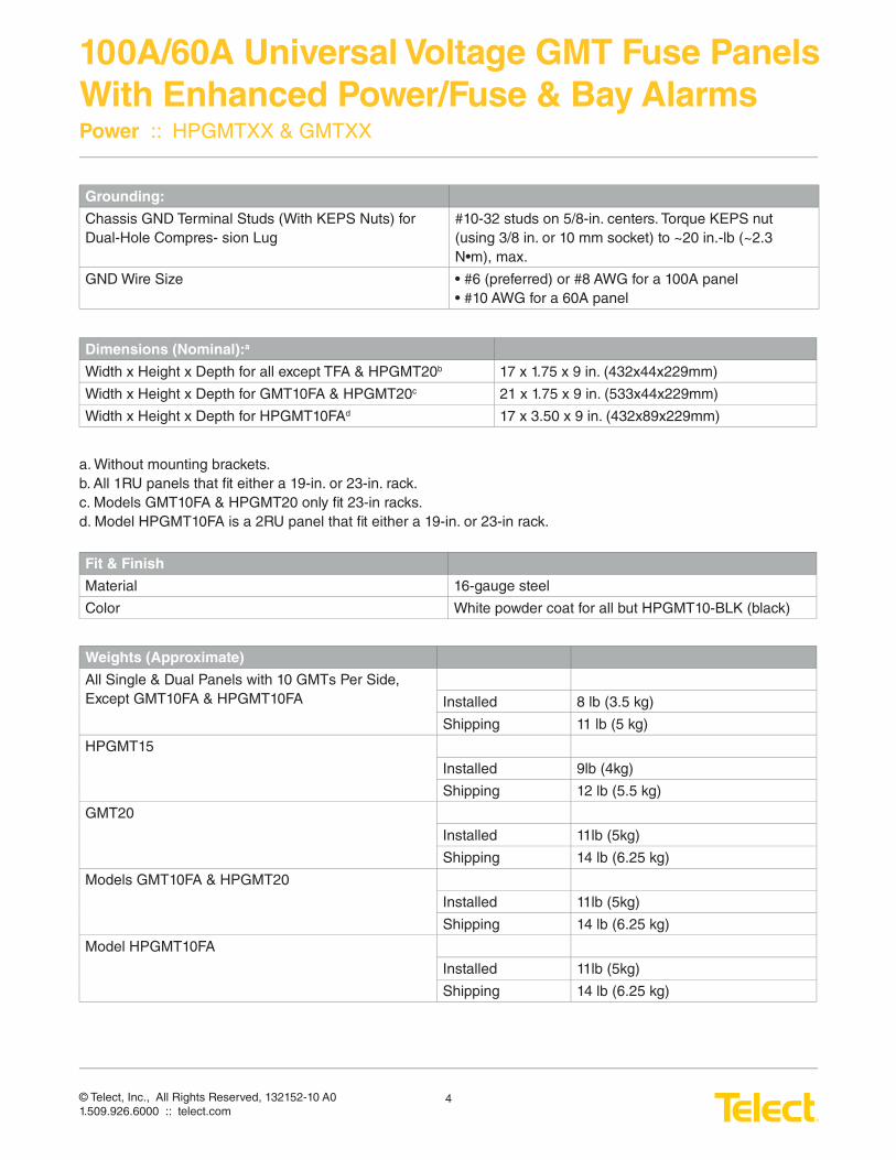
Grounding:
Chassis GND Terminal Studs (With KEPS Nuts) for Dual-Hole Compres- sion Lug
#10-32 studs on 5/8-in. centers. Torque KEPS nut (using 3/8 in. or 10 mm socket) to ~20 in.-lb (~2.3 N•m), max.
GND Wire Size • #6 (preferred) or #8 AWG for a 100A panel • #10 AWG for a 60A panel
Dimensions (Nominal):a
Width x Height x Depth for all except TFA & HPGMT20b 17 x 1.75 x 9 in. (432x44x229mm)
Width x Height x Depth for GMT10FA & HPGMT20c 21 x 1.75 x 9 in. (533x44x229mm)
Width x Height x Depth for HPGMT10FAd 17 x 3.50 x 9 in. (432x89x229mm)
a. Without mounting brackets.b. All 1RU panels that fi t either a 19-in. or 23-in. rack.c. Models GMT10FA & HPGMT20 only fi t 23-in racks.d. Model HPGMT10FA is a 2RU panel that fi t either a 19-in. or 23-in rack.
Fit & Finish
Material 16-gauge steel
Color White powder coat for all but HPGMT10-BLK (black)
Weights (Approximate)
All Single & Dual Panels with 10 GMTs Per Side, Except GMT10FA & HPGMT10FA Installed 8 lb (3.5 kg)
Shipping 11 lb (5 kg)
HPGMT15
Installed 9lb (4kg)
Shipping 12 lb (5.5 kg)
GMT20
Installed 11lb (5kg)
Shipping 14 lb (6.25 kg)
Models GMT10FA & HPGMT20
Installed 11lb (5kg)
Shipping 14 lb (6.25 kg)
Model HPGMT10FA
Installed 11lb (5kg)
Shipping 14 lb (6.25 kg)
© Telect, Inc., All Rights Reserved, 132152-10 A01.509.926.6000 :: telect.com
5
100A/60A Universal Voltage GMT Fuse Panels
With Enhanced Power/Fuse & Bay AlarmsPower :: HPGMTXX & GMTXX
Environment:
Operating Temperature -10°C (14°F) to 55°C (131°F)
Humidity 0 to 90% and noncondensing
1.3 Important Installation Guidelines
• Elevated Operating Ambient - If you install the rack in a closed or multi-unit rack assembly, the operating ambient temperature of the rack environment may be greater than room ambient. Therefore, take care to install the equipment in an environment compatible with the maximum ambient temperature (TMA) specifi ed by the manufacturer.
• Reduced Air Flow - Installation of the equipment in a rack should be such that the amount of air fl ow required for safe operation of the equipment is not compromised.
• Mechanical Loading - Mounting of the equipment in the rack should be such that a hazardous condition is not achieved due to uneven mechanical loading.
• Circuit Overloading - Give consideration to the connection of the equipment to the supply circuit and the ef-fect that overloading of the circuits might have on overcurrent protection and supply wiring. Use appropriate consideration for equipment nameplate ratings when addressing this concern.
• Reliable Earthing - Maintain reliable earthing of rack-mounted equipment. Pay particular attention to supply connections other than direct connections to the branch circuit (e.g., use of power strips).
• Disconnect Device - Incorporate a readily accessible disconnect device in the building installation wiring.
© Telect, Inc., All Rights Reserved, 132152-10 A01.509.926.6000 :: telect.com
6
100A/60A Universal Voltage GMT Fuse Panels
With Enhanced Power/Fuse & Bay AlarmsPower :: HPGMTXX & GMTXX
1.4 Inspection
Please read and understand all instructions before starting installation. If you have questions, contact Telect Technical Support at [email protected] or call 1.509.926.6000.
When you receive the equipment, carefully unpack it and compare it to the packaging list. Please report any defective or missing parts to Telect Quality at [email protected] or call 1.509.926.6000.
Telect is not liable for trasit damaged. If the product is damaged, please report it to the carrier and contact Telect Quality.
1.5 Installation
ALERT!ALERT! Install this product within a restricted access location where access is through the use of a tool,
lock and key, or other means of security, and is controlled by the authority responsible for the location.
This product must be installed and maintained only by qualifi ed technicians.
Verify all connections meet requirements specifi ed in local electric codes or operating company
guidelines before supplying power. Unit shall be protected by a listed circuit breaker or branch-rated fuse
rated maximum 75A (for 60A-rated feeds) and maximum 125A (for 100A-rated feeds).
All panels except Models GMT10FA and HPGMT20 can be mounted in 19-in. EIA racks. Telect also offers bracket kits for WECO and ETSI racks. (See our website at telect.com.) GMT10FA and HPGMT20 only fi t 23-in. racks.
All panels can be fl ush-mounted or extended by 2 in. or 4 in. beyond the rack fl ange.
© Telect, Inc., All Rights Reserved, 132152-10 A01.509.926.6000 :: telect.com
7
100A/60A Universal Voltage GMT Fuse Panels
With Enhanced Power/Fuse & Bay AlarmsPower :: HPGMTXX & GMTXX
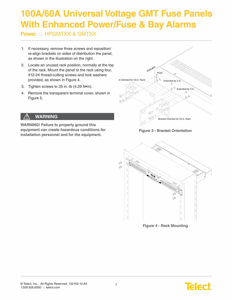
1. If necessary, remove three screws and reposition/re-align brackets on sides of distribution the panel, as shown in the illustration on the right.
2. Locate an unused rack position, normally at the top of the rack. Mount the panel to the rack using four, #12-24 thread-cutting screws and lock washers provided, as shown in Figure 4.
3. Tighten screws to 35 in.-lb (4.29 N•m).
4. Remove the transparent terminal cover, shown in Figure 5.
Flush
Extended by 2 in.
Extended by 4 in.
et Oriented for 19-in. Rack
Bracket Oriented for 23-in. Rack
Figure 3 - Bracket Orientation
Figure 4 - Rack Mounting
WARNING! Failure to properly ground this
equipment can create hazardous conditions for
installation personnel and for the equipment.
WARNING!
© Telect, Inc., All Rights Reserved, 132152-10 A01.509.926.6000 :: telect.com
8
100A/60A Universal Voltage GMT Fuse Panels
With Enhanced Power/Fuse & Bay AlarmsPower :: HPGMTXX & GMTXX
ALERT!
ALERT! Only use components and crimping tools approved by agencies or certifying bodies recognized
in your country or region, such as Underwriter’s Laboratories (UL), TUV, etc.
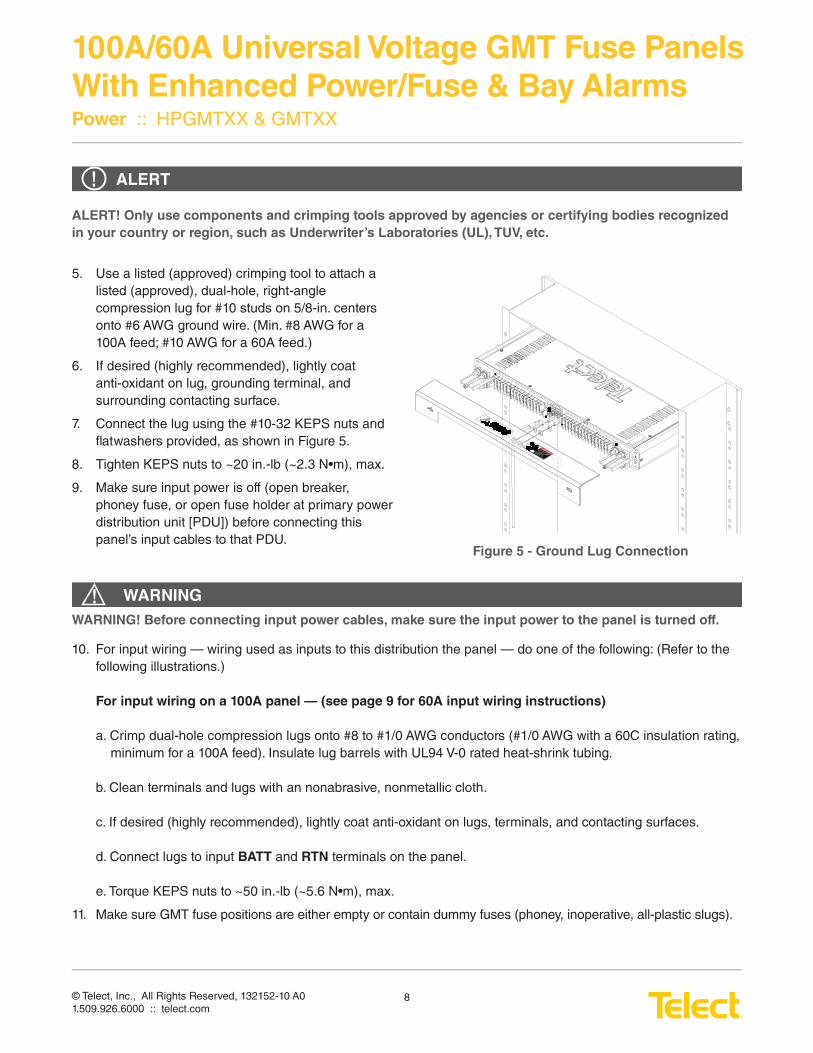
5. Use a listed (approved) crimping tool to attach a listed (approved), dual-hole, right-angle compression lug for #10 studs on 5/8-in. centers onto #6 AWG ground wire. (Min. #8 AWG for a 100A feed; #10 AWG for a 60A feed.)
6. If desired (highly recommended), lightly coat anti-oxidant on lug, grounding terminal, and surrounding contacting surface.
7. Connect the lug using the #10-32 KEPS nuts and fl atwashers provided, as shown in Figure 5.
8. Tighten KEPS nuts to ~20 in.-lb (~2.3 N•m), max.
9. Make sure input power is off (open breaker, phoney fuse, or open fuse holder at primary power distribution unit [PDU]) before connecting this panel’s input cables to that PDU.
10. For input wiring — wiring used as inputs to this distribution the panel — do one of the following: (Refer to the following illustrations.)
For input wiring on a 100A panel — (see page 9 for 60A input wiring instructions)
a. Crimp dual-hole compression lugs onto #8 to #1/0 AWG conductors (#1/0 AWG with a 60C insulation rating, minimum for a 100A feed). Insulate lug barrels with UL94 V-0 rated heat-shrink tubing.
b. Clean terminals and lugs with an nonabrasive, nonmetallic cloth.
c. If desired (highly recommended), lightly coat anti-oxidant on lugs, terminals, and contacting surfaces.
d. Connect lugs to input BATT and RTN terminals on the panel.
e. Torque KEPS nuts to ~50 in.-lb (~5.6 N•m), max.
11. Make sure GMT fuse positions are either empty or contain dummy fuses (phoney, inoperative, all-plastic slugs).
Figure 5 - Ground Lug Connection
WARNING!WARNING! Before connecting input power cables, make sure the input power to the panel is turned off.
© Telect, Inc., All Rights Reserved, 132152-10 A01.509.926.6000 :: telect.com
9
100A/60A Universal Voltage GMT Fuse Panels
With Enhanced Power/Fuse & Bay AlarmsPower :: HPGMTXX & GMTXX
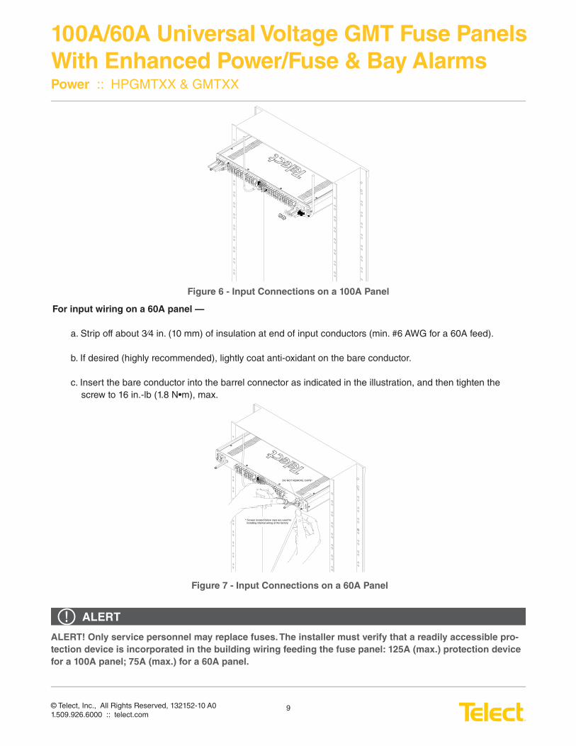
Figure 6 - Input Connections on a 100A Panel
ALERT!ALERT! Only service personnel may replace fuses. The installer must verify that a readily accessible pro-
tection device is incorporated in the building wiring feeding the fuse panel: 125A (max.) protection device
for a 100A panel; 75A (max.) for a 60A panel.
For input wiring on a 60A panel —
a. Strip off about 3⁄4 in. (10 mm) of insulation at end of input conductors (min. #6 AWG for a 60A feed).
b. If desired (highly recommended), lightly coat anti-oxidant on the bare conductor.
c. Insert the bare conductor into the barrel connector as indicated in the illustration, and then tighten the screw to 16 in.-lb (1.8 N•m), max.
DO NOT REMOVE CAPS*
* Screws located below caps are used for installing internal wiring at the factory.
Figure 7 - Input Connections on a 60A Panel
© Telect, Inc., All Rights Reserved, 132152-10 A01.509.926.6000 :: telect.com
10
100A/60A Universal Voltage GMT Fuse Panels
With Enhanced Power/Fuse & Bay AlarmsPower :: HPGMTXX & GMTXX
ALMALMBBAA
MAJOR MINORFUSEPWRFUSEPWR
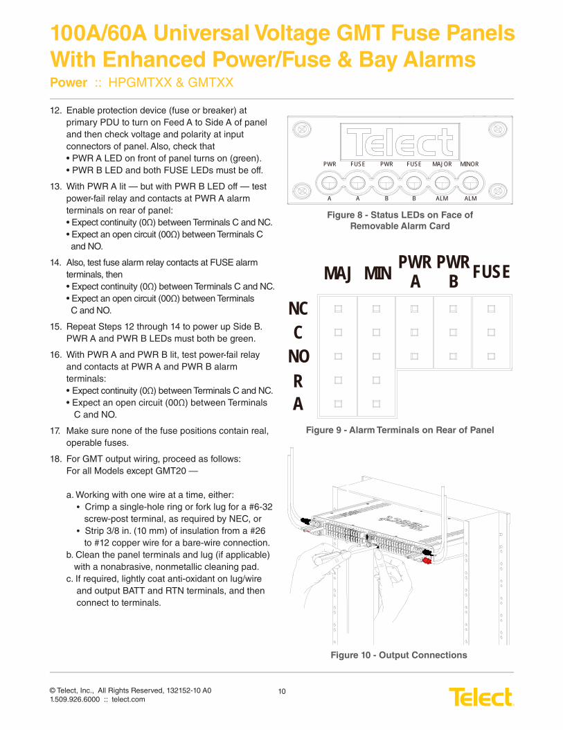
Figure 8 - Status LEDs on Face of
Removable Alarm Card
MAJ MIN PWR A
PWR B FUSE
NCC
NO
AR
Figure 9 - Alarm Terminals on Rear of Panel
Figure 10 - Output Connections
12. Enable protection device (fuse or breaker) at primary PDU to turn on Feed A to Side A of panel and then check voltage and polarity at input connectors of panel. Also, check that • PWR A LED on front of panel turns on (green).• PWR B LED and both FUSE LEDs must be off.
13. With PWR A lit — but with PWR B LED off — test power-fail relay and contacts at PWR A alarm terminals on rear of panel:• Expect continuity (0Ω) between Terminals C and NC.• Expect an open circuit (00Ω) between Terminals C and NO.
14. Also, test fuse alarm relay contacts at FUSE alarmterminals, then• Expect continuity (0Ω) between Terminals C and NC.• Expect an open circuit (00Ω) between Terminals C and NO.
15. Repeat Steps 12 through 14 to power up Side B. PWR A and PWR B LEDs must both be green.
16. With PWR A and PWR B lit, test power-fail relay and contacts at PWR A and PWR B alarm terminals:• Expect continuity (0Ω) between Terminals C and NC.• Expect an open circuit (00Ω) between Terminals C and NO.
17. Make sure none of the fuse positions contain real, operable fuses.
18. For GMT output wiring, proceed as follows:For all Models except GMT20 —
a. Working with one wire at a time, either: • Crimp a single-hole ring or fork lug for a #6-32 screw-post terminal, as required by NEC, or • Strip 3/8 in. (10 mm) of insulation from a #26 to #12 copper wire for a bare-wire connection.b. Clean the panel terminals and lug (if applicable) with a nonabrasive, nonmetallic cleaning pad.c. If required, lightly coat anti-oxidant on lug/wire and output BATT and RTN terminals, and then connect to terminals.
© Telect, Inc., All Rights Reserved, 132152-10 A01.509.926.6000 :: telect.com
11
100A/60A Universal Voltage GMT Fuse Panels
With Enhanced Power/Fuse & Bay AlarmsPower :: HPGMTXX & GMTXX
(NEC specifi es only one load at each output terminal.) Tighten #6-32 screws using either a fl at-tipped screwdriver or Phillips screwdriver (for cross-re- cessed screw heads) to no greater than 6 in.-lb (~0.7 N•m). Connect other end of output wire to load.
For Model GMT20 —
a. Working with one wire at a time, either • Crimp a single-hole ring or fork lug for a #3-48 screw-post terminal, as required by NEC, or • Strip 3/8 in. (10 mm) of insulation from a #30 to #16 copper wire for a bare-wire connection.b. Clean panel terminals and lug (if applicable) with a nonabrasive, nonmetallic cleaning pad.c. If required, lightly coat anti-oxidant on lug/wire and output BATT and RTN terminals, and then connect to terminals. (NEC specifi es only one load at each output terminal.) Tighten #5-40 screws using either a fl at- tipped screwdriver or Phillips screwdriver (for cross-re- cessed screw heads) to no greater than 5 in.-lb (~0.6 N•m). Connect other end of output wire to load.
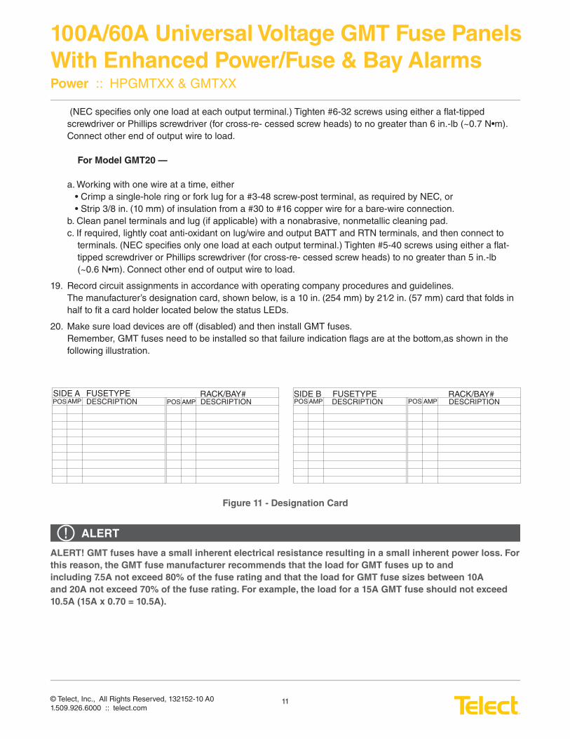
19. Record circuit assignments in accordance with operating company procedures and guidelines.The manufacturer’s designation card, shown below, is a 10 in. (254 mm) by 21⁄2 in. (57 mm) card that folds in half to fi t a card holder located below the status LEDs.
20. Make sure load devices are off (disabled) and then install GMT fuses.Remember, GMT fuses need to be installed so that failure indication fl ags are at the bottom,as shown in the following illustration.
SIDE A SIDE B FUSETYPE FUSETYPERACK/BAY# RACK/BAY#POS POS POS POSAMP AMP AMP AMPDESCRIPTION DESCRIPTION DESCRIPTION DESCRIPTION
Figure 11 - Designation Card
ALERT!ALERT! GMT fuses have a small inherent electrical resistance resulting in a small inherent power loss. For
this reason, the GMT fuse manufacturer recommends that the load for GMT fuses up to and
including 7.5A not exceed 80% of the fuse rating and that the load for GMT fuse sizes between 10A
and 20A not exceed 70% of the fuse rating. For example, the load for a 15A GMT fuse should not exceed
10.5A (15A x 0.70 = 10.5A).
© Telect, Inc., All Rights Reserved, 132152-10 A01.509.926.6000 :: telect.com
12
100A/60A Universal Voltage GMT Fuse Panels
With Enhanced Power/Fuse & Bay AlarmsPower :: HPGMTXX & GMTXX
The total load for all fuse outputs on each side must not exceed the panel’s load rating: either 60A or100A.
21. Test power and polarity at input of each equipment load.
22. If possible, replace one of the operable GMT fuses with a blown fuse to verify that the applicable FUSE Alarm LED turns red. Also, check the FUSE alarm terminals on the rear of the panel:• Expect an open circuit (00Ω) between Terminals C and NC.• Expect continuity (0Ω) between Terminals C and NO. Re-install operable GMT fuse before proceeding.
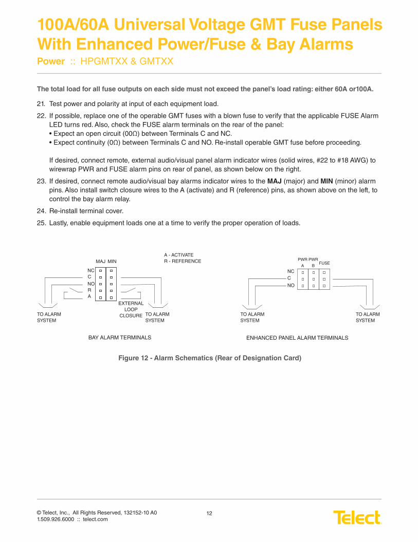
If desired, connect remote, external audio/visual panel alarm indicator wires (solid wires, #22 to #18 AWG) to wirewrap PWR and FUSE alarm pins on rear of panel, as shown below on the right.
23. If desired, connect remote audio/visual bay alarms indicator wires to the MAJ (major) and MIN (minor) alarm pins. Also install switch closure wires to the A (activate) and R (reference) pins, as shown above on the left, to control the bay alarm relay.
24. Re-install terminal cover.
25. Lastly, enable equipment loads one at a time to verify the proper operation of loads.
MAJ MIN
NCC
NORA
TO ALARM SYSTEM
TO ALARM SYSTEM
TO ALARM SYSTEM
TO ALARM SYSTEM
EXTERNALLOOP
CLOSURE
A - ACTIVATER - REFERENCE
NCC
NO
PWR
A
PWR
BFUSE
BAY ALARM TERMINALS ENHANCED PANEL ALARM TERMINALS
Figure 12 - Alarm Schematics (Rear of Designation Card)
© Telect, Inc., All Rights Reserved, 132152-10 A01.509.926.6000 :: telect.com
13
100A/60A Universal Voltage GMT Fuse Panels
With Enhanced Power/Fuse & Bay AlarmsPower :: HPGMTXX & GMTXX
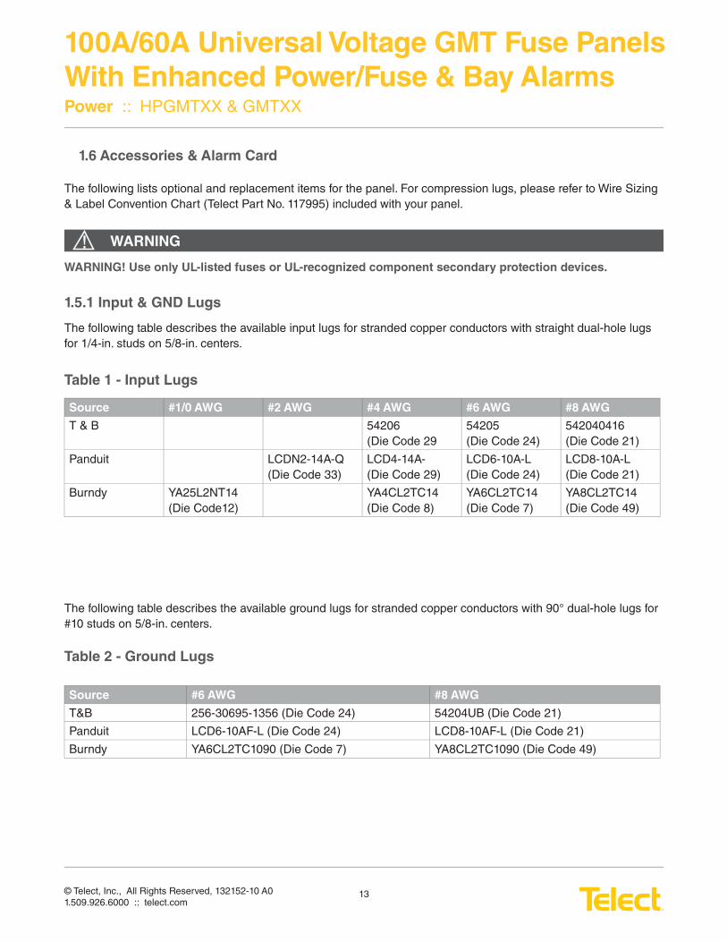
1.6 Accessories & Alarm Card
The following lists optional and replacement items for the panel. For compression lugs, please refer to Wire Sizing & Label Convention Chart (Telect Part No. 117995) included with your panel.
WARNING!WARNING! Use only UL-listed fuses or UL-recognized component secondary protection devices.
1.5.1 Input & GND Lugs
The following table describes the available input lugs for stranded copper conductors with straight dual-hole lugs for 1/4-in. studs on 5/8-in. centers.
Table 1 - Input Lugs
Source #1/0 AWG #2 AWG #4 AWG #6 AWG #8 AWG
T & B 54206 (Die Code 29
54205 (Die Code 24)
542040416 (Die Code 21)
Panduit LCDN2-14A-Q (Die Code 33)
LCD4-14A- (Die Code 29)
LCD6-10A-L (Die Code 24)
LCD8-10A-L (Die Code 21)
Burndy YA25L2NT14 (Die Code12)
YA4CL2TC14 (Die Code 8)
YA6CL2TC14 (Die Code 7)
YA8CL2TC14 (Die Code 49)
The following table describes the available ground lugs for stranded copper conductors with 90° dual-hole lugs for #10 studs on 5/8-in. centers.
Table 2 - Ground Lugs
Source #6 AWG #8 AWG
T&B 256-30695-1356 (Die Code 24) 54204UB (Die Code 21)
Panduit LCD6-10AF-L (Die Code 24) LCD8-10AF-L (Die Code 21)
Burndy YA6CL2TC1090 (Die Code 7) YA8CL2TC1090 (Die Code 49)
© Telect, Inc., All Rights Reserved, 132152-10 A01.509.926.6000 :: telect.com
14
100A/60A Universal Voltage GMT Fuse Panels
With Enhanced Power/Fuse & Bay AlarmsPower :: HPGMTXX & GMTXX
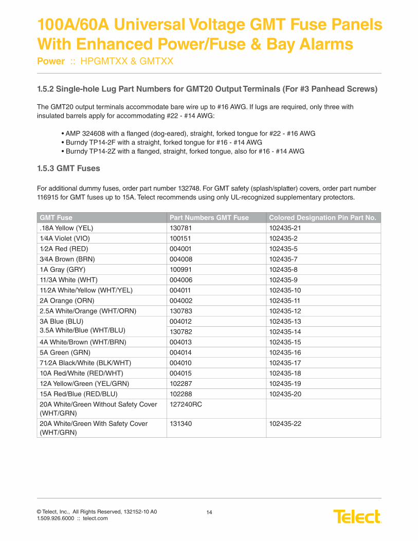
1.5.2 Single-hole Lug Part Numbers for GMT20 Output Terminals (For #3 Panhead Screws)
The GMT20 output terminals accommodate bare wire up to #16 AWG. If lugs are required, only three withinsulated barrels apply for accommodating #22 - #14 AWG:
• AMP 324608 with a fl anged (dog-eared), straight, forked tongue for #22 - #16 AWG • Burndy TP14-2F with a straight, forked tongue for #16 - #14 AWG • Burndy TP14-2Z with a fl anged, straight, forked tongue, also for #16 - #14 AWG
1.5.3 GMT Fuses
For additional dummy fuses, order part number 132748. For GMT safety (splash/splatter) covers, order part number 116915 for GMT fuses up to 15A. Telect recommends using only UL-recognized supplementary protectors.
GMT Fuse Part Numbers GMT Fuse Colored Designation Pin Part No.
.18A Yellow (YEL) 130781 102435-21
1⁄4A Violet (VIO) 100151 102435-2
1⁄2A Red (RED) 004001 102435-5
3⁄4A Brown (BRN) 004008 102435-7
1A Gray (GRY) 100991 102435-8
11/3A White (WHT) 004006 102435-9
11⁄2A White/Yellow (WHT/YEL) 004011 102435-10
2A Orange (ORN) 004002 102435-11
2.5A White/Orange (WHT/ORN) 130783 102435-12
3A Blue (BLU)3.5A White/Blue (WHT/BLU)
004012 102435-13
130782 102435-14
4A White/Brown (WHT/BRN) 004013 102435-15
5A Green (GRN) 004014 102435-16
71⁄2A Black/White (BLK/WHT) 004010 102435-17
10A Red/White (RED/WHT) 004015 102435-18
12A Yellow/Green (YEL/GRN) 102287 102435-19
15A Red/Blue (RED/BLU) 102288 102435-20
20A White/Green Without Safety Cover (WHT/GRN)
127240RC
20A White/Green With Safety Cover (WHT/GRN)
131340 102435-22
© Telect, Inc., All Rights Reserved, 132152-10 A01.509.926.6000 :: telect.com
15
100A/60A Universal Voltage GMT Fuse Panels
With Enhanced Power/Fuse & Bay AlarmsPower :: HPGMTXX & GMTXX
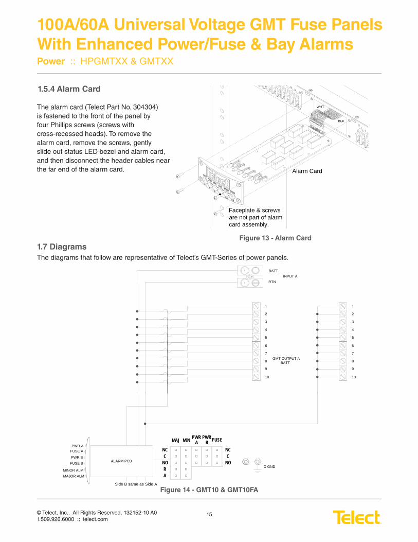
1.5.4 Alarm Card
The alarm card (Telect Part No. 304304)is fastened to the front of the panel by four Phillips screws (screws with cross-recessed heads). To remove the alarm card, remove the screws, gentlyslide out status LED bezel and alarm card, and then disconnect the header cables nearthe far end of the alarm card.
1.7 Diagrams
The diagrams that follow are representative of Telect’s GMT-Series of power panels.
ALARM PCB
PWR A FUSE A
C GND
RTN
BATTINPUT A
PWR B
GMT OUTPUT ABATT
5
1
3
4
2
FUSE B
MINOR ALMMAJOR ALM
MAJ MIN PWR A
PWR B FUSE
NCC
NORA
NCC
NO
6
7
8
9
10
5
1
3
4
2
6
7
8
9
10
Side B same as Side A
Alarm Card
BLK
WHT
Faceplate & screws are not part of alarm card assembly.
Figure 13 - Alarm Card
Figure 14 - GMT10 & GMT10FA
© Telect, Inc., All Rights Reserved, 132152-10 A01.509.926.6000 :: telect.com
16
100A/60A Universal Voltage GMT Fuse Panels
With Enhanced Power/Fuse & Bay AlarmsPower :: HPGMTXX & GMTXX
ALA
RM
PC
B
PW
R A
F
US
E A
C G
ND
RT
N
BA
TT
INP
UT
A
PW
R B
GM
T O
UT
PU
T A
BA
TT
51 3 42
FU
SE
B
MIN
OR
ALM
MA
JOR
ALM
MAJ
MIN
PWR
A
PWR
B
FUSE
NC C NO R A
NC C NO
6 7 8 9 10
GM
T O
UT
PU
T A
RT
N
51 3 42 6 7 8 9 10
Sid
e B
sam
e as
Sid
e A
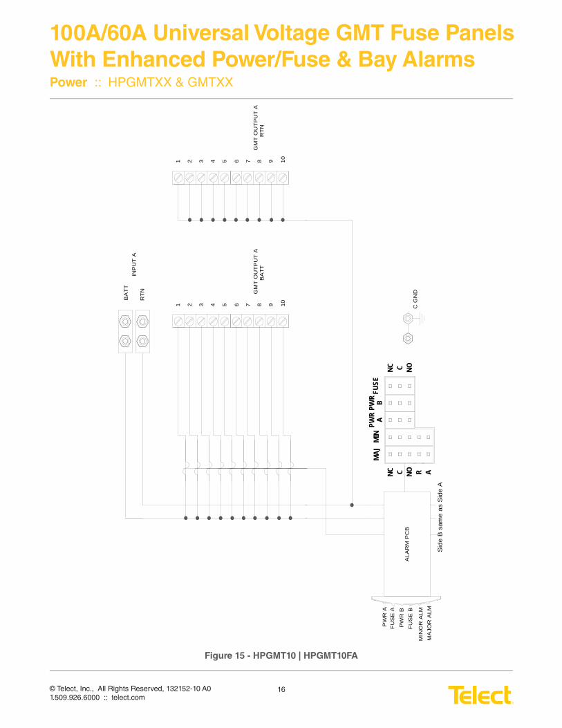
Figure 15 - HPGMT10 | HPGMT10FA
© Telect, Inc., All Rights Reserved, 132152-10 A01.509.926.6000 :: telect.com
17
100A/60A Universal Voltage GMT Fuse Panels
With Enhanced Power/Fuse & Bay AlarmsPower :: HPGMTXX & GMTXX
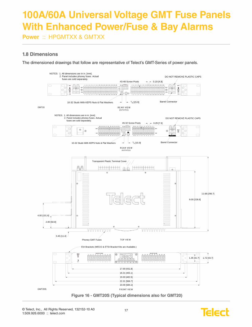
1.8 Dimensions
The dimensioned drawings that follow are representative of Telect’s GMT-Series of power panels.
19.00 [482.6]
18.31 [465.1]
17.00 [431.8]
1.72 [43.7]1.25 [31.7]
9.00 [228.6]
11.68 [296.7]
0.45 [11.4]
Barrel Connector
#6-32 Screw Posts
58 [15.9]10-32 Studs With KEPS Nuts & Flat Washers
Phoney GMT Fuses
NOTES: 1. All dimensions are in in. [mm].2. Panel includes phoney fuses. Actual fuses are sold separately.
Transparent Plastic Terminal Cover
EIA Brackets (WECO & ETSI Bracket Kits are Available.)
R E A R VIE W (R OT AT E D)
T OP VIE W
F R ONT VIE W
ALMALMBBAA
MAJORMINORFUSEPWRFUSEPWR
22.31 [566.7]
23.00 [584.2]
2.00 [50.8]
4.00 [101.6]
DO NOT REMOVE PLASTIC CAPS
1 2 3 4 5 6 7 8 9 1020A GMT FUSE MAX 20A GMT FUSE MAX
11 12 13 14 15 16 17 18 19 20
0.29 [7.5]20 19 18 17 16 15 14 13 12 11 10 9 8 7 6 5 4 3 2 1MAJ MIN PWR
APWR B FUSE
NCC
NORA
BATT
RTN
BATT
RTN
GMT20S
20 19 18 17 16 15 14 13 12 11 10 9 8 7 6 5 4 3 2 1
4824
-+-
V- - -
SINGLEINPUTBUS60A
INPUT60AMAX
Barrel Connector
#3-48 Screw Posts
58 [15.9]10-32 Studs With KEPS Nuts & Flat Washers
NOTES: 1. All dimensions are in in. [mm].2. Panel includes phoney fuses. Actual fuses are sold separately.
R E A R V IE W (R OT A T E D)
DO NOT REMOVE PLASTIC CAPS
0.19 [4.8]
INPUT60AMAX
1 2 3 4 5 6 7 8 9 10 11 12 13 14 15BATT
RTN
INPUT60AMAX
BATT
RTN1 2 3 4 5 6 7 8 9 10 11 12 13 14 15
2 3 4 5 6 7 8 9 10 11 12 13 14 15
1 2 3 4 5 6 7 8 9 10 11 12 13 14 15
MAJ MIN PWR A
PWR B FUSE
NCC
NOAR
BATT
RTN
BATT
RTN
116 17 18 19 20
16 17 18 19 20
16 17 18 19 20
16 17 18 19 20
A B
GMT20
Figure 16 - GMT20S (Typical dimensions also for GMT20)
© Telect, Inc., All Rights Reserved, 132152-10 A01.509.926.6000 :: telect.com
18
100A/60A Universal Voltage GMT Fuse Panels
With Enhanced Power/Fuse & Bay AlarmsPower :: HPGMTXX & GMTXX
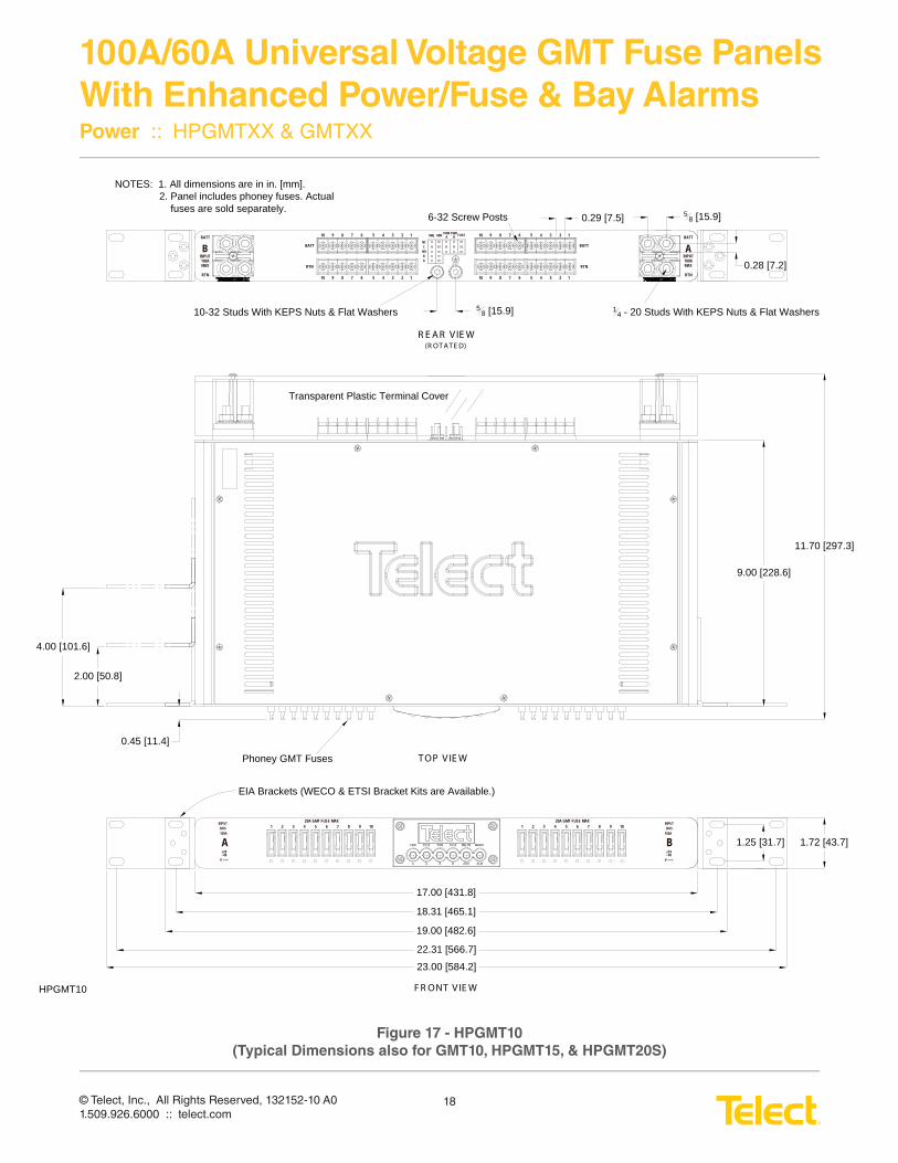
19.00 [482.6]
18.31 [465.1]
17.00 [431.8]
1.72 [43.7]1.25 [31.7]
9.00 [228.6]
11.70 [297.3]
0.45 [11.4]
0.28 [7.2]
58 [15.9]
14 - 20 Studs With KEPS Nuts & Flat Washers
6-32 Screw Posts 0.29 [7.5]
58 [15.9]10-32 Studs With KEPS Nuts & Flat Washers
Phoney GMT Fuses
NOTES: 1. All dimensions are in in. [mm].2. Panel includes phoney fuses. Actual fuses are sold separately.
Transparent Plastic Terminal Cover
EIA Brackets (WECO & ETSI Bracket Kits are Available.)
R E A R VIE W (R OT AT E D)
T OP VIE W
F R ONT VIE W
ALMALMBBAA
MINORMAJORFUSEPWRFUSEPWR
22.31 [566.7]
23.00 [584.2]
2.00 [50.8]
4.00 [101.6]
1 2 3 4 5 6 7 8 9 1020A GMT FUSE MAX 20A GMT FUSE MAX
1 2 3 4 5 6 7 8 9 10
BINPUT100AMAX
10 9 8 7 6 5 4 3 2 1BATT
RTN
AINPUT100AMAX
BATT
RTN
MAJ MIN PWR A
PWR B FUSE
NCC
NO
AR
BATT
RTN
BATT
RTN
HPGMT10
10 9 8 7 6 5 4 3 2 1
10 9 8 7 6 5 4 3 2 1
10 9 8 7 6 5 4 3 2 1
B
INPUTBUS
100A
A
INPUTBUS100A
4824
-+-
V - - -4824
-+-
V - - -
Figure 17 - HPGMT10
(Typical Dimensions also for GMT10, HPGMT15, & HPGMT20S)
© Telect, Inc., All Rights Reserved, 132152-10 A01.509.926.6000 :: telect.com
19
100A/60A Universal Voltage GMT Fuse Panels
With Enhanced Power/Fuse & Bay AlarmsPower :: HPGMTXX & GMTXX
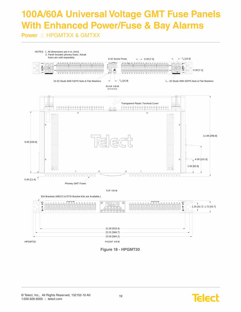
NOTES: 1. All dimensions are in in. [mm].2. Panel includes phoney fuses. Actual fuses are sold separately.
ALMALMBBAA
MAJORMINORFUSEPWRFUSEPWR
23.00 [584.2]
1.72 [43.7]
22.31 [566.7]
1.25 [31.7]
21.00 [533.4]
2.00 [50.8]
4.00 [101.6]
9.00 [228.6]
Phoney GMT Fuses
Transparent Plastic Terminal Cover
EIA Brackets (WECO & ETSI Bracket Kits are Available.)
T OP VIE W
F R ONT V IE W
11.69 [296.8]
0.45 [11.4]
A B
INPUTBUS100A
INPUTBUS100A
6 7 8 9 10 11 12 13 14 15 16 17 18 19 2020A GMT FUSE MAX 20A GMT FUSE MAX
1 2 3 4 5 6 7 8 9 10 11 12 13 1451 2 3 4 16 17 1815 19 20
HPGMT20
0.28 [7.2]
58 [15.9]
14 - 20 Studs With KEPS Nuts & Flat Washers
6-32 Screw Posts 0.29 [7.5]
58 [15.9]10-32 Studs With KEPS Nuts & Flat Washers
R E A R VIE W (R OT A T E D)
INPUT100AMAX
20 19 18 17 16 15 14 13 12 11 10 9 8 7 6BATT
RTN
INPUT100AMAX
BATT
RTN
MAJ MIN PWR A
PWR B FUSE
NCC
NO
AR
BATT
RTN
BATT
RTN
5 4 3 2 1
20 19 18 17 16 15 14 13 12 11 10 9 8 7 6 5 4 3 2 1
20 19 18 17 16 15 14 13 12 11 10 9 8 7 6 5 4 3 2 1
20 19 18 17 16 15 14 13 12 11 10 9 8 7 6 5 4 3 2 1
4824
-+-
V- - -4824
-+-
V- - -
B A
Figure 18 - HPGMT20
© Telect, Inc., All Rights Reserved, 132152-10 A01.509.926.6000 :: telect.com
20
100A/60A Universal Voltage GMT Fuse Panels
With Enhanced Power/Fuse & Bay AlarmsPower :: HPGMTXX & GMTXX
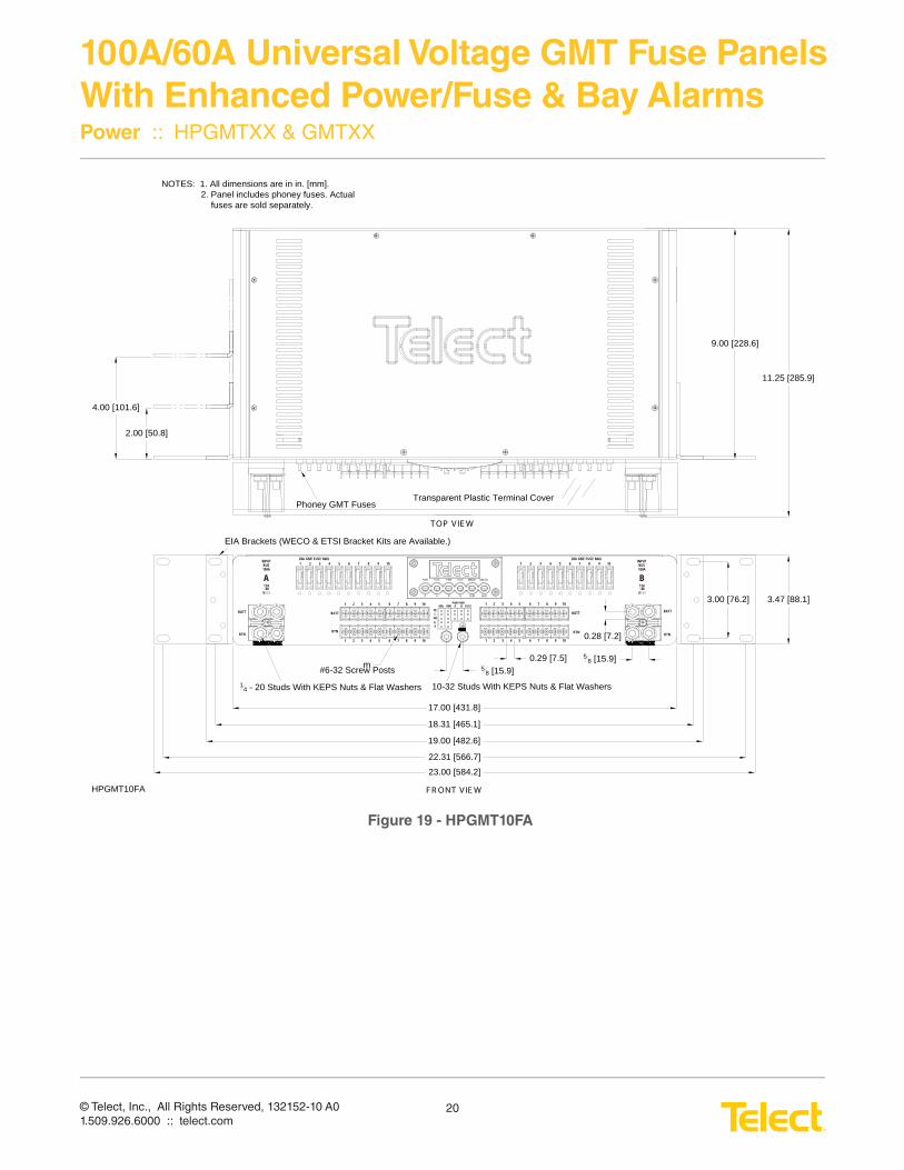
19.00 [482.6]
18.31 [465.1]
17.00 [431.8]
3.47 [88.1]
9.00 [228.6]
11.25 [285.9]
0.28 [7.2]
14 - 20 Studs With KEPS Nuts & Flat Washers
#6-32 Screw Posts 58 [15.9]
10-32 Studs With KEPS Nuts & Flat Washers
Phoney GMT Fuses
NOTES: 1. All dimensions are in in. [mm].2. Panel includes phoney fuses. Actual fuses are sold separately.
Transparent Plastic Terminal Cover
EIA Brackets (WECO & ETSI Bracket Kits are Available.)
T OP V IE W
F R ONT V IE W
ALMALMBBAA
MAJORMINORFUSEPWRFUSEPWR
22.31 [566.7]
23.00 [584.2]
2.00 [50.8]
4.00 [101.6]
3.00 [76.2]
1 2 3 4 5 6 7 8 9 1020A GMT FUSE MAX 20A GMT FUSE MAX
1 2 3 4 5 6 7 8 9 10
1 2 3 4 5 6 7 8 9 10
BATT
RTN
BATT
RTN1 2 3 4 5 6 7 8 9 10
1 2 3 4 5 6 7 8 9 10
1 2 3 4 5 6 7 8 9 10
MAJ MINPWR A
PWR B FUSE
NCC
NO
AR
BATT
RTN
BATT
RTN
58 [15.9]0.29 [7.5]
m
HPGMT10FA
A
INPUTBUS100A
4824
-+-
V - - -
B
INPUTBUS100A
4824
-+-
V- - -
Figure 19 - HPGMT10FA
© Telect, Inc., All Rights Reserved, 132152-10 A01.509.926.6000 :: telect.com
21
100A/60A Universal Voltage GMT Fuse Panels
With Enhanced Power/Fuse & Bay AlarmsPower :: HPGMTXX & GMTXX
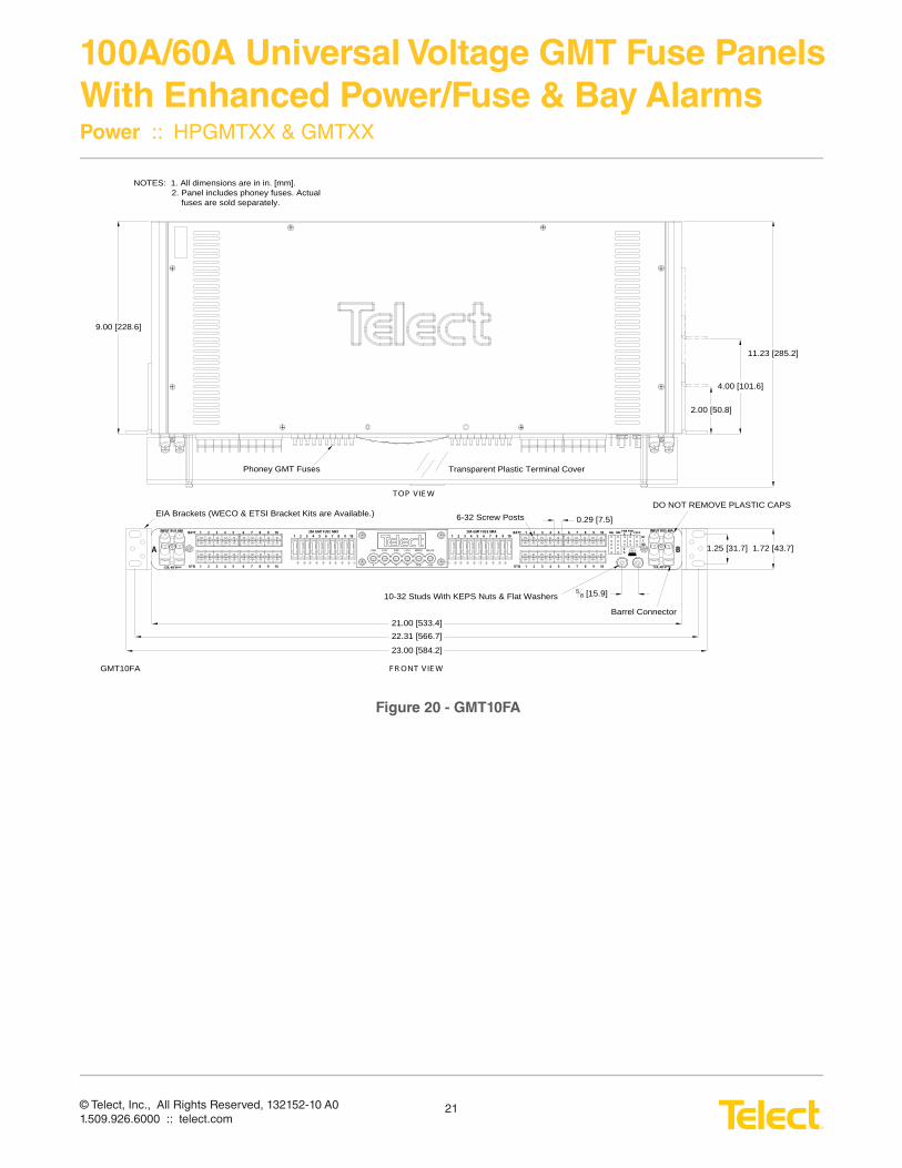
Barrel Connector
6-32 Screw Posts
58 [15.9]10-32 Studs With KEPS Nuts & Flat Washers
NOTES: 1. All dimensions are in in. [mm].2. Panel includes phoney fuses. Actual fuses are sold separately.
ALMALMBBAA
MAJORMINORFUSEPWRFUSEPWR
DO NOT REMOVE PLASTIC CAPS
A B
INPUT BUS 60A6 7 8 9 10
20A GMT FUSE MAX51 2 3 4 6 7 8 9 10
20A GMT FUSE MAX51 2 3 4
MAJ MIN PWR A
PWR B FUSE
NCC
NO
AR
1 2 3 4 5 6 7 8 9 10
1 2 3 4 5 6 7 8 9 10
BATT
RTN
1 2 3 4 5 6 7 8 9 10
1 2 3 4 5 6 7 8 9 10
BATT
RTN
INPUT BUS 60A
23.00 [584.2]
1.72 [43.7]
22.31 [566.7]
1.25 [31.7]
21.00 [533.4]
2.00 [50.8]
4.00 [101.6]
11.23 [285.2]
9.00 [228.6]
Phoney GMT Fuses Transparent Plastic Terminal Cover
EIA Brackets (WECO & ETSI Bracket Kits are Available.)
T OP V IE W
F R ONT V IE W
0.29 [7.5]
GMT10FA
24,-48 V- - -+- 24,-48 V- - -+-
Figure 20 - GMT10FA
© Telect, Inc., All Rights Reserved, 132152-10 A01.509.926.6000 :: telect.com
22
100A/60A Universal Voltage GMT Fuse Panels
With Enhanced Power/Fuse & Bay AlarmsPower :: HPGMTXX & GMTXX
This page intentionally left blank.