building-integrated solar energy devices based on
TRANSCRIPT

Building-Integrated Solar Energy Devices based
on Wavelength Selective Films
A THESIS SUBMITTED TO THE FACULTY OF THE GRADUATE SCHOOL OF
THE UNIVERSITY OF MINNESOTA BY
Tejas Ulavi
IN PARTIAL FULFILLMENT OF THE REQUIREMENTS FOR THE DEGREE OF
MASTER OF SCIENCE
Dr. Jane H. Davidson, Adviser
June, 2013

© Tejas Ulavi, 2013

i
Acknowledgements
I would like to thank my adviser, Dr. Jane Davidson for her constant support and
guidance throughout my research and graduate education, which made the journey easier
than it would have otherwise been. Her patience and feedback, especially during the
writing of this thesis is deeply appreciated. In all my future endeavors, Prof. Davidson
will remain a constant source of inspiration.
I would also like to thank Dr. Wojciech Lipinski for his expert technical guidance
at various stages of this research, and my colleagues at the Solar Energy Lab for honest
feedback and advice.
I am grateful to Tim Hebrink for providing concentrators and wavelength
selective film for the prototype, and for his painstaking efforts and help in attaching the
film to the concentrators.
I would like to acknowledge Dr. Thomas Kuehn for allowing me to use the
infrastructure and radiation measurement equipment of his undergraduate Thermal
Environmental Engineering laboratory to conduct my experiments.
I thank Becky Alexander at the School of Architecture for providing a scene
rendering for the hybrid window concept.
The financial support from the University of Minnesota’s Institute for Renewable
Energy and the Environment is greatly appreciated.
Finally, I want to thank my parents, grandparents and friends for their constant
encouragement and support.

ii
Abstract
A potentially attractive option for building integrated solar is to employ hybrid
solar collectors which serve dual purposes, combining solar thermal technology with
either thin film photovoltaics or daylighting. In this study, two hybrid concepts, a hybrid
photovoltaic/thermal (PV/T) collector and a hybrid ‘solar window’, are presented and
analyzed to evaluate technical performance. In both concepts, a wavelength selective film
is coupled with a compound parabolic concentrator (CPC) to reflect and concentrate the
infrared portion of the solar spectrum onto a tubular absorber. The visible portion of the
spectrum is transmitted through the concentrator to either a thin film Cadmium Telluride
(CdTe) solar panel for electricity generation or into the interior space for daylighting.
Special attention is given to the design of the hybrid devices for aesthetic building
integration. An adaptive concentrator design based on asymmetrical truncation of CPCs
is presented for the hybrid solar window concept.
The energetic and spectral split between the solar thermal module and the PV or
daylighting module are functions of the optical properties of the wavelength selective
film and the concentrator geometry, and are determined using a Monte Carlo Ray-
Tracing (MCRT) model. Results obtained from the MCRT can be used in conjugation
with meteorological data for specific applications to study the impact of CPC design
parameters including the half-acceptance angle 𝜃𝑐, absorber diameter 𝐷 and truncation on
the annual thermal and PV/daylighting efficiencies.
The hybrid PV/T system is analyzed for a rooftop application in Phoenix, AZ.
Compared to a system of the same area with independent solar thermal and PV modules,
the hybrid PV/T provides 20% more energy, annually. However, the increase in total

iii
delivered energy is due solely to the addition of the thermal module and is achieved at an
expense of a decrease in the annual electrical efficiency from 8.8% to 5.8% due to
shading by the absorber tubes. For this reason, the PV/T hybrid is not recommended over
other options in new installations.
The hybrid solar window is evaluated for a horizontal skylight and south and east
facing vertical windows in Minneapolis, MN. The predicted visible transmittance for the
solar window is 0.66 to 0.73 for single glazed systems and 0.61 to 0.67 for double glazed
systems. The solar heat gain coefficient and the U-factor for the window are comparable
to existing glazing technology. Annual thermal efficiencies of up to 24% and 26% are
predicted for the vertical window and the horizontal skylight respectively. Experimental
measurements of the solar thermal component of the window confirm the trends of the
model. In conclusion, the hybrid solar window combines the functionality of an energy
efficient fenestration system with hybrid thermal energy generation to provide a
compelling solution towards sustainable design of the built environment.

iv
Table of Contents
Acknowledgements…………………………………………………………………………i
Abstract ……………………………………………………………………………………ii
Table of Contents …………………………………………………………………………iv
List of Tables…………………………………………………………………………….viii
List of Figures.…………………………………………………………………………….ix
Chapter 1 Introduction…………………………………………………………………..1
Chapter 2 Analysis of a Hybrid PV/T Concept based on a Wavelength Selective
Film……..…………………………………………………………………………………3
2.1 Introduction ……………………………………………………………………….4
2.2 PV/T Design……………………………………………………………………….6
2.3 Numerical Approach.………………………………………………………………9
2.3.1 Monte Carlo Ray-Tracing (MCRT) Model………………………………11
2.3.2 Annual Thermal and Electrical Efficiency……………………………….14
2.4 Results……………………………………………………………………………18
2.4.1 MCRT……………………………………………………………………18
2.4.2 Parametric Study…………………………………………………………20
2.4.2.1 Effect of concentrator geometry…………………………………20
2.4.2.2 Effect of tube diameter…………………………………………...22
2.4.3 Case Study……………………………………………………………….24
2.5 Conclusion…………………………………………………………………….....27
2.6 Nomenclature…………………………………………………………………….28
2.7 References…………………………………………..……………………………32

v
Chapter 3 Analysis of a Hybrid Solar Window for Building Integration…………..35
3.1 Introduction……………………………………………………………………....35
3.2 Wavelength Selective Film………………………………………………………39
3.3 Design Approach………………………………………………………………...40
3.4 Numerical Model………………………………………………………………...42
3.4.1 MCRT……………………………………………………………………42
3.4.2 Annual Thermal Efficiency………………………………………………45
3.4.3 Evaluation of Fenestration……………………………………………….46
3.5 Results………………………………..…………………………………………..48
3.5.1 MCRT……………………………………………………………………48
3.5.2 Case Study……………………………………….………………………49
3.5.2.1 Horizontal Skylight………………………………………………50
3.5.2.2 Vertical Window…………………………………………………52
3.5.3 Comparison with Commercial Fenestration Systems…………………....52
3.6 Conclusion…………………………………………………………………….…55
3.7 Tables and Diagrams……………………………………………………….…….57
3.8 Nomenclature………………………………………………………………….…67
3.9 References…………………………………………………………………….….69
Chapter 4 Experimental Validation of the Hybrid Solar Window……………….…73
4.1 Construction of the Prototype………………………………………………...….73
4.2 Experimental Apparatus……………………………………………….…………76
4.3 Data Analysis…………………………………………………………………….78
4.4 Results……………………………………………………………………………80

vi
4.5 Conclusion……………………………………………………………………….84
4.6 Nomenclature………………………………………………….…………………86
Chapter 5 Conclusions……………………………………………………………...…..89
5.1 Summary and Conclusions…………………………………………………...….91
5.2 Recommendations for Future Work……………………………………………...92
Bibliography ……………………………………………………………………………94
Appendices
Appendix A CPC Geometry……………………………………………………………99
Appendix B Additional notes on the MCRT…………………………………………...100
B.1 Convergence Criteria for MCRT simulations…………………………………….100
B.2 Ray-tracing algorithm……………………………………………………………..102
B.3 Implementation of specular error…………………………………………………104
B.4 Component angles 𝜃𝑥𝑦 and 𝜃𝑦𝑧 of a three dimensional ray……………………..105
Appendix C Results from MCRT……………………………………………………..106
C.1 Hybrid PV/T………………....…………………………………………………..106
C.2 Hybrid Solar Window…………………..…………………..……………………114
Appendix D Additional notes on the thermal model…………………………………117
D.1 Convective heat transfer within the CPC cavity…………..……………………..117
D.2 Radiative heat transfer within the CPC cavity………….……………………….120
D.3 Thermophysical properties of working fluids…………….……………………...121
Appendix E Uncertainty Analysis.……………………………………………………123

vii
List of Tables
Table Page
2.1 Heat transfer coefficients between different components of the thermal
module
16
2.2 Fixed and variable parameters for the parametric study 21
2.3 Truncated parameters for different CPC geometries used in Fig. 2.9 23
3.1 Assumptions and system properties for the annual thermal model 57
3.2 Standard NFRC environmental conditions 57
3.3 The NFRC visible transmittance, solar heat gain coefficient and U-factor
the vertical solar window application for considered CPC geometries
57
3.4 The NFRC visible transmittance, solar heat gain coefficient and U-factor
for commercial single and double glazed window systems
58
4.1 Inputs to the thermal model 80
B.1 Optical properties of the CPC components for re-radiation in the IR 120
E.1 Uncertainty in measured quantities 124
E.2 Uncertainty in thermophysical properties for ethylene glycol/water
solution
124
E.3 Uncertainty in calculated values, obtained using root-sum-of-squares
method
124

viii
List of Figures
Figure Page
1.1 Overview of U.S energy consumption [1] 1
2.1 Design concept for the hybrid PV/T collector 7
2.2 CPC geometry – Nominal and truncated parameters 8
2.3 Spectral reflectance of the wavelength selective film at 0o and 60o
incidence
10
2.4 Quantum efficiency (left) for CdTe [26] and spectral reflectance (right)
for the selective film at normal incidence
10
2.5 Monte Carlo Ray-Trace in the CPC cavity 12
2.6 Thermal resistive network for the thermal module 16
2.7 Parameters obtained through MCRT as a function of 𝜃𝑥𝑦 and 𝜃𝑦𝑧 for a
CPC with 𝜃𝑐 = 45o, 𝐷 = 0.03m and 𝐶𝑒 = 1.4 (a) 𝑔𝑏,𝑟𝑇 , 𝑔𝑑
𝑇 (b) 𝑔𝑏,𝑟𝑃𝑉,
𝑔𝑑𝑃𝑉(c) 𝑊𝜆,𝑏,𝑟 ,𝑊𝜆,𝑑
19
2.8 Annual thermal (left) and PV (right) efficiency, 𝐷 = 0.03m, �� = 0.015
kg/s-m2
21
2.9 Annual thermal (a) and PV (b) efficiency as a function of 𝜃𝑐 and 𝐶𝑒, 𝐷 =
0.03m, �� = 0.015 kg/s-m2
23
2.10 Annual thermal (a) and PV (b) efficiency as a function of 𝜃𝑐 and 𝐷, �� =
0.015 kg/s-m2
24
2.11 A schematic for (a) the hybrid PV/T system and (b) the independent
system of PV and T collectors
25
2.12 Total annual output (kWh) for the hybrid collector and the independent
system at (a) 𝜃𝑐 = 25o, (b) 𝜃𝑐 = 40o and (c) 𝜃𝑐 = 55o, 𝐷 = 0.02m, �� =
0.015 kg/s-m2
25
2.13 Gain (Eq. 31) as a function of 𝜃𝑐, for 𝐷 = 0.02m, �� = 0.015 kg/s-m2 26
3.1 Design concept for the hybrid solar window 59
3.2 Spectral directional reflectance for the wavelength selective film at 0o and
60o incidence
59

ix
Figure Page
3.3 CIE Photopic luminosity function [1] 60
3.4 (a) Hybrid window/skylight overall dimensions (b) Typical cross-section
of the hybrid system with component thicknesses
60
3.5 (a) Asymmetrical truncation of a CPC geometry showing truncated and
untruncated parameters (b) Resultant asymmetrically truncated CPC
61
3.6 Truncated CPC geometries for (a), (b) vertical window and (c) horizontal
skylight for maximum optical efficiency at the absorber tube for the
respective half-acceptance angles
61
3.7 MCRT for a single ray in the asymmetrically truncated CPC cavity 62
3.8 (a) The fraction of incident beam radiation reaching the absorber tube as
a function of 𝜃𝑥𝑦 and 𝜃𝑦𝑧 (b) 1-Incident and 2-transmitted spectrum for
diffuse radiation (c) 1-Incident and 2-transmitted spectrum for beam
radiation normal to the glazing
62
3.9 Monthly transmitted radiation for single glazed horizontal skylight and
south and east facing windows
63
3.10 Visible transmittance for diffuse radiation as a function of 𝜃𝑐 for single
(solid) and double (dashed) glazed horizontal skylight application. Curves
1, 4 are for glazing alone; 2, 5 are for glazing plus wavelength selective
mirror; and 3, 6 are for window assembly
63
3.11 Annual thermal efficiency for single (solid line) and double (dashed line)
glazed horizontal skylights as a function of 𝜃𝑐 64
3.12 Visible transmittance for diffuse radiation as a function of 𝜃𝑐 for single
(solid) and double (dashed) glazed vertical window application. Curves 1,
4 are for glazing alone; 2, 5 are for glazing plus wavelength selective
mirror; and 3, 6 are for window assembly
64
3.13 Annual thermal efficiency for single (solid line) and double (dashed line)
glazed (a) south facing and (b) east facing vertical window as a function
of 𝜃𝑐
65
3.14 A visual rendering of the the exterior and interior appearance of a
building facade employing hybrid solar windows and skylights.
[Rendering made by Becky Alexander, School of Architecture,
University of Minnesota]
66

x
Figure Page
4.1 (a) CPC geometry (b) Endplate and draft angle for the thermoformed
concentrator
74
4.2 The Hybrid solar window prototype 75
4.3 Experimental setup for measuring thermal efficiency of the hybrid solar
window
77
4.4 Calculated vertical components of radiation – global vertical irradiance,
beam vertical irradiance and diffuse vertical irradiance
81
4.5 Measured inlet, outlet and ambient temperatures 82
4.6 Comparison between the measured (green) and predicted (blue) useful
energy. Total energy on the vertical surface (black) and the predicted
energy gain (red) are given for reference
82
A.1 CPC coordinates in terms of parameters 𝜌, 𝜑 99
B.1 Convergence of numerical results for (a) beam radiation (normal to CPC
axis) and (b) diffuse radiation as a function of launched rays for 𝜃𝑐 = 25o,
𝐷 = 0.03m
101
B.2 Convergence of numerical results for diffuse visible transmittance as a
function of number of launched rays for 𝜃𝑐 = 25o, 𝐷 = 0.03m
101
B.3 Monte Carlo Ray-Tracing algorithm, ray-tracing module 102
B.4 Monte Carlo Ray-Tracing algorithm (Primary loop) 103
B.5 Modified surface normal to account for specular error 104
B.6 The polar and azimuth angles for a ray in the local coordinate system 105
C.1 MCRT results for hybrid PV/T: 𝜃𝑐 = 25o, 𝐷 = 0.03m 106
C.2 MCRT results for hybrid PV/T: 𝜃𝑐 = 30o, 𝐷 = 0.03m 106
C.3 MCRT results for hybrid PV/T: 𝜃𝑐 = 35o, 𝐷 = 0.03m 106
C.4 MCRT results for hybrid PV/T: 𝜃𝑐 = 40o, 𝐷 = 0.03m 107
C.5 MCRT results for hybrid PV/T: 𝜃𝑐 = 45o, 𝐷 = 0.03m 107
C.6 MCRT results for hybrid PV/T: 𝜃𝑐 = 50o, 𝐷 = 0.03m 107

xi
Figure Page
C.7 MCRT results for hybrid PV/T: 𝜃𝑐 = 55o, 𝐷 = 0.03m 107
C.8 MCRT results for hybrid PV/T: 𝜃𝑐 = 25o, 𝐷 = 0.02m 108
C.9 MCRT results for hybrid PV/T: 𝜃𝑐 = 30o, 𝐷 = 0.02m 108
C.10 MCRT results for hybrid PV/T: 𝜃𝑐 = 35o, 𝐷 = 0.02m 108
C.11 MCRT results for hybrid PV/T: 𝜃𝑐 = 40o, 𝐷 = 0.02m 108
C.12 MCRT results for hybrid PV/T: 𝜃𝑐 = 45o, 𝐷 = 0.02m 109
C.13 MCRT results for hybrid PV/T: 𝜃𝑐 = 50o, 𝐷 = 0.02m 109
C.14 MCRT results for hybrid PV/T: 𝜃𝑐 = 55o, 𝐷 = 0.02m 109
C.15 MCRT results for hybrid PV/T: 𝜃𝑐 = 25o, 𝐷 = 0.025m 109
C.16 MCRT results for hybrid PV/T: 𝜃𝑐 = 30o, 𝐷 = 0.025m 110
C.17 MCRT results for hybrid PV/T: 𝜃𝑐 = 35o, 𝐷 = 0.025m 110
C.18 MCRT results for hybrid PV/T: 𝜃𝑐 = 40o, 𝐷 = 0.025m 110
C.19 MCRT results for hybrid PV/T: 𝜃𝑐 = 45o, 𝐷 = 0.025m 110
C.20 MCRT results for hybrid PV/T: 𝜃𝑐 = 50o, 𝐷 = 0.025m 111
C.21 MCRT results for hybrid PV/T: 𝜃𝑐 = 55o, 𝐷 = 0.025m 111
C.22 MCRT results for hybrid PV/T: 𝜃𝑐 = 25o, 𝐷 = 0.03m, 𝐶𝑒 = 1.4 111
C.23 MCRT results for hybrid PV/T: 𝜃𝑐 = 25o, 𝐷 = 0.03m, 𝐶𝑒 = 1.7 111
C.24 MCRT results for hybrid PV/T: 𝜃𝑐 = 30o, 𝐷 = 0.03m, 𝐶𝑒 = 1.4 112
C.25 MCRT results for hybrid PV/T: 𝜃𝑐 = 30o, 𝐷 = 0.03m, 𝐶𝑒 = 1.7 112
C.26 MCRT results for hybrid PV/T: 𝜃𝑐 = 35o, 𝐷 = 0.03m, 𝐶𝑒 = 1.4 112
C.27 MCRT results for hybrid PV/T: 𝜃𝑐 = 40o, 𝐷 = 0.03m, 𝐶𝑒 = 1.2 112
C.28 MCRT results for hybrid PV/T: 𝜃𝑐 = 40o, 𝐷 = 0.03m, 𝐶𝑒 = 1.4 113
C.29 MCRT results for hybrid PV/T: 𝜃𝑐 = 45o, 𝐷 = 0.03m, 𝐶𝑒 = 1.2 113

xii
Figure Page
C.30 MCRT results for hybrid PV/T: 𝜃𝑐 = 50o, 𝐷 = 0.03m, 𝐶𝑒 = 1.2 113
C.31 MCRT results for vertical window: 𝜃𝑐 = 25o, 𝐷 = 0.016m 114
C.32 MCRT results for vertical window: 𝜃𝑐 = 30o, 𝐷 = 0.016m 114
C.33 MCRT results for vertical window: 𝜃𝑐 = 35o, 𝐷 = 0.016m 114
C.34 MCRT results for vertical window: 𝜃𝑐 = 40o, 𝐷 = 0.016m 115
C.35 MCRT results for vertical window: 𝜃𝑐 = 45o, 𝐷 = 0.016m 115
C.36 MCRT results for horizontal skylight: 𝜃𝑐 = 25o, 𝐷 = 0.016m 115
C.37 MCRT results for horizontal skylight: 𝜃𝑐 = 30o, 𝐷 = 0.016m 115
C.38 MCRT results for horizontal skylight: 𝜃𝑐 = 35o, 𝐷 = 0.016m 116
C.39 MCRT results for horizontal skylight: 𝜃𝑐 = 40o, 𝐷 = 0.016m 116
C.40 MCRT results for horizontal skylight: 𝜃𝑐 = 45o, 𝐷 = 0.016m 116
D.1 The absorber tube and the CPC cavity approximated as eccentric
cylinders
118

1
Chapter 1
Introduction
Buildings are the primary sinks of global energy resources. Figure 1.1 shows that
out of the 19% total world energy consumption represented by the US, commercial and
residential building sectors collectively contribute to 41%. Only 9% of the energy
consumption in the building sector is obtained from sustainable sources of energy
(hydroelectric, wood, solar, wind, geothermal). Solar energy represents less than 1% of
this portion [1]. Challenges associated with solar technology include low efficiency of
solar electricity, availability of less expensive conventional fossil fuel based sources of
energy and a lack of architecturally aesthetic and functional building integrated solar
energy collection and distribution systems. As relatively mature solar technologies such
as solar thermal systems for domestic hot water and solar photovoltaics decline in costs,
it is important to adapt the built environment to harness the solar resource. Ideally,
sustainable building design will entail the integration of these devices to exterior walls or
roofs consistent with the overall architectural intent of the building.
Fig. 1.1 Overview of U.S energy consumption [1]

2
In the present work, two concepts are presented for hybrid solar energy generation
with special attention to aesthetics and building integration. The concepts were conceived
to use wavelength selective films developed by the 3M Companies. Specifically, the film
of interest has a high transmission band in the visible portion of the solar spectrum, which
closely matches the quantum efficiency curve for a Cadmium Telluride (CdTe) solar cell,
and a high reflectance band in the near infrared (for wavelengths up to 1850nm). For the
present study, the wavelength selective film is utilized in combination with non-tracking
compound parabolic concentrators to concentrate the infrared spectrum on an absorber
tube to produce sensible heat. The transmitted visible spectrum is used for two alternative
applications: to generate electricity via thin film CdTe, or for daylighting an interior
space.
This thesis is organized into two papers that are self-sustaining in scope and
presentation and can be read independently. The papers share common design principles
and analysis techniques. Chapter 2 consists of a paper submitted at the ASME Energy
Sustainability 2013 conference. It presents and analyzes a hybrid photovoltaic/thermal
(PV/T) collector. Chapter 3 analyzes an architecturally integrated hybrid solar window
design that generates useful thermal energy that can be used to heat water, in addition to
the primary function of daylighting the interior space. The paper presented in Chapter 3
has been submitted to the Solar Energy (Elseiver). A prototype of the solar window was
built and tested. Preliminary results for the thermal efficiency of the built prototype are
presented in Chapter 4. Chapter 5 presents the overall conclusions of the research and
recommendations for future work. A bibliography is presented at the end of each chapter.

3
References
[1] DOE. Buildings Energy Data Book, Chapter 1 Buildings Sector. United States
Department of Energy, 2011

4
Chapter 2
Analysis of a Hybrid PV/T Concept based on a Wavelength
Selective Film1
The technical performance of a non-tracking hybrid PV/T concept that uses a
wavelength selective film is modeled. The wavelength selective film is coupled with a
compound parabolic concentrator to reflect and concentrate the infrared portion of the
solar spectrum onto a tubular absorber while transmitting the visible portion of the
spectrum to an underlying thin-film photovoltaic module. The optical performance of the
CPC/selective film is obtained through Monte Carlo Ray-Tracing. The CPC geometry is
optimized for maximum total energy generation for a roof-top application. Applied to a
rooftop in Phoenix, Arizona USA, the hybrid PV/T provides 20% more energy compared
to a system of the same area with independent solar thermal and PV modules, but the
increase is achieved at the expense of a decrease in the electrical efficiency from 8.8% to
5.8%.
2.1 Introduction
Hybrid collectors incorporating solar energy conversion to both thermal energy
and electricity within a single device are popularly referred to as PV/T systems [1-3].
Non-tracking PV/T systems are an enticing concept for buildings where there is demand
for space heating, hot water and electrical energy, and where roof space is limited [4, 5].
______________________ 1This paper was co-authored by Tim Hebrink and Jane H. Davidson
5
Concentrating PV/T collectors have been considered to extract more energy from a given
solar cell area [6-8], but require tracking and are thus not as attractive for residential
buildings as they are for commercial applications. Two general approaches have been
proposed to manage the thermal and electrical performance in such hybrid systems.
In the first and most common approach, the PV is cooled via buoyancy-driven or
forced flow using a liquid (usually water) [4-13], air [14-17] or a combination [18]. Most
PV/T concepts employ glazing to achieve higher thermal efficiency, at the expense of
lowering of the electrical efficiency [9-12]. Zondag et al. [9] predicted the annual
performance of nine PV/T concepts using a PV laminate with a predicted annual
efficiency of 7.2%. For implementation in The Netherlands, predicted efficiencies are
7.6%/24% for unglazed and 6.1-6.6%/38-35% for glazed PV/T. The range reported for
glazed collectors is due to differences in position and geometry of the cooling channel.
Recently, Dupeyrat et al. [13] proposed the use of fluorinated ethylene propylene (FEP)
lamination to replace PV glass covers, and alternate PV encapsulation material to
improve the optical performance of liquid PV/T systems.
In the second approach, the insolation is split into spectral bands optimized for
each generation technology. The PV operating temperature is lowered if the spectrum of
the incident radiation matches the quantum efficiency band of the PV cell. The radiant
energy outside this band can be converted to heat via a solar thermal collector. Spectral
filters are classified as multilayer filters (present work), liquid absorptive filters, heat
mirrors, prism spectrum splitters, luminescent filters, or holographic filters [19]. System
development is limited by cost constraints and various limitations relating to application
of spectrum splitting optics to real systems [19, 20]. Among the optical limitations is the

6
reduction in filter performance at incident angles different from the design angle [20]. To
counter this issue in tracking applications, dish receivers or heliostat field receivers have
been used to limit the range of incident angles at the beam splitter [21, 22]. Although a
number of innovative concept designs have been proposed for compact collectors
utilizing beam splitting [23], none has been commercialized.
In the present study, we consider using spectral band splitting for a non-tracking
hybrid collector intended for building applications (Fig. 2.1). A wavelength selective
film is attached to a compound parabolic concentrator (CPC) which concentrates the
infrared portion of the solar spectrum on to an absorber tube while transmitting the
visible portion to a thin film PV module. A Monte-Carlo ray tracing (MCRT) model
predicts the optical performance of the CPC with a wavelength selective film, and the
energetic and spectral split between the PV and thermal modules as a function of
incidence angle for a range of CPC geometries as defined by the half acceptance angle,
tube diameter and degree of truncation. The results of the MCRT can be used in
conjugation with meteorological data to calculate the annual and electrical collector
efficiencies. A roof-top collector for Phoenix, AZ is considered in the present study. A
parametric study optimizes the half-acceptance angle, the tube diameter and the
concentration factor of the CPC for maximum total energy generation. Finally, a case
study is presented which compares the annual efficiency of the hybrid collector to an
independent system of thermal and PV modules.
2.2 PV/T Design
The concentrator geometry, the type of the PV module and the optical properties
of the wavelength selective film are the major design parameters. Here, we consider a

7
Fig. 2.1 Design concept for the hybrid PV/T collector
hybrid collector with 2m x 1m aperture area. The height is constrained to 0.13m for
aesthetic installation on residential or commercial rooftops. A thin film CdTe film is
selected for the PV module to match the characteristics of the wavelength selective film.
The CPC concentrator is geometrically defined by the tube diameter 𝐷, the
nominal half-acceptance angle 𝜃𝑐 and the effective geometrical concentration factor 𝐶𝑒,
or truncation (Fig. 2.2) [24]. For a perfectly specular concentrator surface, all radiation
within the acceptance angle is collected at the absorber tube. The tube diameter 𝐷
determines the size of the concentrator, and the nominal half-acceptance angle 𝜃𝑐
determines the maximum geometric concentration factor for the nominal CPC,
𝐶𝑚𝑎𝑥 = 1
sin𝜃𝑐 (2.1)
The truncation of the top portion of a CPC is common practice to save reflector
IR film
attached
on CPC
Absorber tube
Thin film
PV
Incident
radiation
IR
Visible

8
Fig. 2.2 CPC geometry – Nominal and truncated parameters
material and to reduce the vertical dimension of the CPC. The truncation results in lower
geometric concentration, but modifies the field of view of the concentrator to allow
diffuse radiation outside the nominal half-acceptance angle to reach the absorber [25].
Figure 2.2 graphically shows the effect of truncation. 𝜃𝑐 and 𝐻𝑚𝑎𝑥 represent the nominal
parameters of the CPC, yielding a geometric concentration factor given by Eq. (2.1). The
line 𝐿 truncates the CPC symmetrically to yield the truncated parameters: 𝜃𝑑, the
truncated half-acceptance angle and He, the effective truncated height of the CPC. With
truncation, the effective geometric concentration factor is 𝐶𝑒, defined as the ratio of
truncated aperture area and the area of the absorber.
The wavelength selective film belongs to a group of infrared reflective mirrors
that utilize constructive quarter-wave interference in multi-layer optical films
comprising multiple layers of transparent dielectric materials. Alternating layers of high
refractive index polymers and low refractive index polymers are coextruded into optical
stacks containing 100 to 1000 layers with layer thicknesses of approximately a quarter of
the wavelength of radiation to be reflected [26]. The manufacturer has developed
coextrusion and orientation processes that yield layer thickness control at the nanometer
D
CPC cover
𝐻𝑒
𝜃𝑐
𝜃𝑑
𝐻𝑚𝑎𝑥
Line of truncation - L

9
scale. Each polymer layer pair contains polymers of differing refractive indices and
works constructively with the next layer to create broad reflection bands. Figure 2.3
shows the spectral reflectance for normal and 60o off-normal incidence for the
wavelength selective film considered for the present study. The data for 1110nm
were measured by spectroscopy. For > 1110nm the curves are those expected for a
selective film under development. The reflection bands shift to lower wavelengths by
~20% for 60o off-normal incidence according to Fresnel reflection and phase thickness
equations. Birefringent polymers with matched z-direction (along the thickness)
refractive indices are used so that the reflectivity of p-polarized light is independent of
incidence angle, in spite of the band-edge shift [26]. The increase in reflectivity for s-
polarized light by about 2-3% for incidence higher than 45o is neglected. The spectral
absorptance for the film is negligible in the band considered.
Thin film Cadmium Telluride (CdTe) PV cells are selected for two reasons. First, as
shown in Fig. 2.4, the quantum efficiency curve [27] matches the transmitted spectrum of
the wavelength selective film at normal incidence. Second, thin film cells can be arranged
so that the detrimental effect of shading by the absorber tubes is minimized. Thin film
solar cells can be oriented in a direction such that all cells are shaded equally, and thus
current mismatch can be avoided, albeit with a reduction in electrical efficiency [28].
2.3 Numerical Approach
A 3-D Monte Carlo Ray-Tracing (MCRT) model was implemented to predict the
reflectance of the CPC/selective film as a function of the direction and wavelength of the
incident radiation for a range of CPC geometries. The value of these results is that they

10
Fig. 2.3 Spectral reflectance of the wavelength selective film at 0o and 60o incidence
Fig. 2.4 Quantum efficiency (left) for CdTe [26] and spectral reflectance (right) for the
selective film at normal incidence
00.10.20.30.40.50.60.70.80.9
1
200 450 700 950 1200 1450 1700 1950 2200 2450
ρm
λ (nm)
60o0o
0
10
20
30
40
50
60
70
80
90
100
0
10
20
30
40
50
60
70
80
90
100
300 400 500 600 700 800 900
τ λ(%
)
ηq
(%)
λ (nm)
Selective film (0o)
CdTe

11
can be used to determine the thermal and electrical efficiency of the collector for any
roof-top application. In the present study, we selected a roof-top in Phoenix, AZ to
illustrate the annual efficiency of the collector.
2.3.1 MCRT Model
The following parameters were calculated with the MCRT model:
(𝑔𝑏,𝑟𝑇 ≡
𝐺𝑏,��𝑇
𝐺𝑏,��), (𝑔𝑑
𝑇 ≡𝐺𝑑𝑇
𝐺𝑑) – The fractions of incident beam radiation (as a function of
incident direction), and incident diffuse radiation reaching the absorber tube,
respectively
(𝑔𝑏,𝑟𝑃𝑉 ≡
𝐺𝑏,��𝑃𝑉
𝐺𝑏,��), (𝑔𝑑
𝑃𝑉 ≡𝐺𝑑𝑃𝑉
𝐺𝑑) – The fractions of incident beam radiation (as a function
of incident direction), and incident diffuse radiation transmitted to the PV,
respectively
𝑊𝜆,𝑏,𝑟 and 𝑊𝜆,𝑑 – The PV module spectral weighting factors for beam radiation as a
function of incident direction, and for diffuse radiation, respectively
The gas in the CPC was assumed to be non-participating and the reflector surface
was assumed to be 1.5 mm thick, with a specular reflectance 𝜌𝑠 of 0.95. The direction of
the incident beam radiation, 𝑟, is represented by component angles 𝜃𝑥𝑦 and 𝜃𝑦𝑧 in the 𝑥𝑦
and 𝑦𝑧 planes. The ray path was computed separately in the two planes and was
superimposed to obtain a 3-D solution. Figure 2.5 depicts the MCRT for a single ray.
Each MCRT simulation consists of a stochastically large number of rays, 𝑁𝑖,𝑏 for beam
radiation and 𝑁𝑖,𝑑 for diffuse radiation, being launched from the cover. To achieve
convergence, 𝑁𝑖,𝑏 and 𝑁𝑖,𝑑 are chosen as 105 and 106, respectively. Each ray has a

12
direction (𝜃𝑥𝑦, 𝜃𝑦𝑧), an energy 𝐺
𝑁𝑖, a wavelength 𝜆𝑖 and an origin (𝑥0, 𝑦0, 𝑧0). The origin
has a uniform random distribution over the CPC cover area. For beam radiation, a series
of MCRT simulations were performed by varying 𝜃𝑥𝑦 and 𝜃𝑦𝑧 from 0o to 60o in intervals
of 1o and 5o respectively, to obtain data from the entire range of directions expected in a
roof-top collector. For diffuse radiation, 𝜃𝑥𝑦 and 𝜃𝑦𝑧 were chosen based on standard
MCRT distributions for the zenith and azimuth angles for diffuse emission from an
isotropic surface [29]. The spectral distribution of the rays was obtained by considering
the sun to be a blackbody at 5777K [30].
The wavelength for a launched ray was selected by computing the right-hand side
of Eq. (2.2) numerically over discrete wavelength intervals of 5 nm until the value closest
to the generated random number was obtained.
𝑅𝜆 = 1
𝜎𝑇4∫ 𝐸𝑏𝜆 𝑑𝜆𝜆
0= 𝑓0−𝜆𝑇 (2.2)
Fig. 2.5 Monte Carlo Ray-Trace in the CPC cavity
Cover τc
𝜃𝑥𝑦 𝜃𝑦𝑧
(𝑥1, 𝑥2, 𝑥3)
Film
𝜌𝑚(𝜆, 𝜃𝑚)
z
y
x
End plates
τ=1
(𝑥0, 𝑥0, 𝑥0)

13
Once a ray was launched from the aperture plane, its path was traced through the
CPC cavity, accounting for randomized surface interactions within the cavity until the ray
either (i) struck the absorber tube, (ii) was transmitted to the PV module or (iii) was lost
through the cover or ends of the CPC. The path of the ray in the 𝑥𝑦 and 𝑦𝑧 planes can be
represented by straight lines. The intersection of the ray with the cover and the absorber
were calculated by simple geometrical relations. Intersection with the CPC was
calculated numerically using the equation of the CPC curve for tubular absorbers defined
in [31].
Whenever the ray intersected a surface, a random reflectance 𝑅𝜌 was generated to
determine a statistically meaningful outcome over the large sample of rays – either
reflection or transmission at the cover or the CPC/selective film, based on the surface
properties. The transmittance of the cover 𝜏𝑐 is based on Snell’s law for refraction and
Bouguer’s law for absorption losses in the cover [32]. For the selective film, the
reflectance depends upon the angle of incidence at the point of intersection, 𝜃𝑚, and the
wavelength 𝜆𝑖. 𝜃𝑚 is the resultant of the intersection angles in the 𝑥𝑦 and the 𝑦𝑧 planes.
A specular error 𝜃𝑠 having a normal distribution with a standard deviation 𝜎𝑠 = 3 mrad
accounts for the irregularities in the CPC surface. The film reflectance given by Eq. (2.3)
was calculated in terms of film spectral reflectance at normal incidence, based on the
band-edge shifts for the selective film.
𝜌𝑚(𝜆, 𝜃𝑚) = 𝜌𝑚 (𝜆
𝑓(𝜃𝑚), 0) (2.3)
𝑓(𝜃𝑚) is a fourth order polynomial in 𝜃𝑚 that has different forms for 𝜆 < 1350 nm
and 𝜆 > 1350 nm, representative of the two band-edges.

14
The number and wavelength of each ray were tracked iteratively, and the fractions
of beam and diffuse radiation available for the thermal and PV modules were derived
from the results of the ray-tracing.
𝑔𝑏,𝑟𝑇 =
𝑁𝑎,𝑏
𝑁𝑖,𝑏 , 𝑔𝑑
𝑇 =𝑁𝑎,𝑑
𝑁𝑖,𝑑 (2.4), (2.5)
𝑔𝑏,𝑟𝑃𝑉 =
𝑁𝑡,𝑏
𝑁𝑖,𝑏, 𝑔𝑑
𝑃𝑉 =𝑁𝑡,𝑑
𝑁𝑖,𝑑 (2.6), (2.7)
The spectral weighting factors for beam radiation and diffuse radiation, 𝑊𝜆,𝑏,𝑟 and
𝑊𝜆,𝑑 , have a value from 0 to 1 and modify the PV module efficiency to account for
transmission losses through the wavelength selective film and shading effects due to the
absorber tubes. For an independent PV module without the film, the spectral weighting
factors equal unity. For the present application, they are defined by Eqs. (2.8) and (2.9),
weighting the spectral characteristics of the wavelength selective film by the quantum
efficiency.
𝑊𝜆,𝑏,𝑟 =∑ 𝜆𝑡,𝑏∙𝜂𝑞(𝜆𝑡,𝑏)𝑁𝑡,𝑏
∑ 𝜆𝑖,𝑏∙𝜂𝑞(𝜆𝑖,𝑏)𝑁𝑖,𝑏
, 𝑊𝜆,𝑑 =∑ 𝜆𝑡,𝑑∙𝜂𝑞(𝜆𝑡,𝑑)𝑁𝑡,𝑑
∑ 𝜆𝑖,𝑑∙𝜂𝑞(𝜆𝑖,𝑑)𝑁𝑖,𝑑
(2.8), (2.9)
2.3.2 Annual thermal and electrical efficiency
The efficiencies of the solar thermal and PV modules were calculated
independently using the results obtained from the MCRT. A quasi-steady state 1-D
energy balance was applied for the thermal module. A selective coating of black chrome
on nickel was assumed for the absorber tubes and weighted absorptance of 0.945 was
calculated [32]. A fixed fluid inlet temperature of 293K was assumed. To simplify the
mathematical analysis, a number of assumptions were made. The heat flux at the absorber
tube was assumed uniform over the circumference. Flow through the absorber tube was

15
assumed to be uniform and fully developed. Conduction losses through the low iron glass
cover were neglected. The annual thermal efficiency is given by Eq. (2.10) [32].
𝜂𝑡ℎ = 1
𝐴𝑐∑
𝑛𝐴𝑎𝐹𝑅[𝑆− 𝑈𝐿(𝑇𝑓𝑖−𝑇∞)]
𝐺ℎ𝑜𝑢𝑟𝑠 (2.10)
The solar radiation incident on the absorber tube, 𝑆, was obtained by interpolating
from the MCRT results for the direction of beam radiation obtained from the hourly
TMY2 data [34], and accounting for transmittance of the low iron glass cover and the
absorptance of the absorber tube.
𝑆 = (𝐺𝑏,𝑟𝑇 + 𝐺𝑑
𝑇)𝜏𝑐𝛼 (2.11)
The overall thermal loss coefficient 𝑈𝐿 was computed from the equivalent thermal
resistance network shown in Fig. 2.6.
𝑈𝐿 = 1
𝑅𝑡ℎ𝐴𝑎 (2.12)
Table 2.1 lists the assumed heat transfer coefficients. The convective losses in the CPC
cavity were approximated by treating the cavity as a horizontal annulus formed by
eccentric cylinders [35]. An effective outer diameter 𝐷𝑜 was calculated. An
experimentally derived factor, 𝑓𝑟𝑎𝑡 having a value of 0.55 [36] was used in the
calculation of the convective heat loss from the absorber to the reflector and the cover.
The equivalent emittances, 휀𝑎−𝑐, 휀𝑎−𝑚 and 휀𝑐−𝑚 were calculated from relations derived
in literature [24].
For CPCs with tubular absorbers, the heat removal factor is given by Eq. (2.13).
𝐹𝑅 = ��𝑐𝑝
𝐴𝑐𝑈𝐿[1 − 𝑒𝑥𝑝 (−
𝐴𝑐𝑈𝐿𝐹′
��𝑐𝑝)] (2.13)
where
𝐹′ = [1𝑈𝐿⁄
1
𝑈𝐿+
𝐷
ℎ𝑓𝑖𝐷𝑖+(
𝐷
2𝑘ln𝐷
𝐷𝑖)] (2.14)

16
Fig. 2.6 Thermal resistive network for the thermal module
Table 2.1 Heat transfer coefficients between different components of the thermal module
Convective heat transfer Radiative heat transfer
hc,a−c =𝑁𝑢𝐷𝑘𝑎𝑖𝑟
𝐷(1+𝑓𝑟𝑎𝑡) [35, 36]
hr,a−c =εa−cσ(Ta
4−Tc4)
(Ta−Tc) [24,36]
hc,a−m = frat ∙ hc,a−c [36] hr,a−m =εa−mσ(Ta
4−Tm4)
(Ta−Tm) [24,36]
hc,c−∞ = 2.8 + 3.0vw [32]
hr,c−b =
σεc(Tc+Tsky)(Tc2+Tsky
2 )(Tc−Tsky)
(Tc−T∞)
hcd,c−m = 4(kmt
L2) [36]
(Conductive heat transfer coefficient) hr,c−m =
εc−mσ(Tc4−Tm
4)
(Tc−Tm) [24,36]
hc,m−∞ = (0.6 +0.387RaDo
1/6
[1+(0.559/Pr)9/16]8/27)
2kair
Do
[37]
hr,m−b =εmσ(Tm
4−T∞4)
(Tm−T∞) [24,36]
𝑇∞ Ambient
𝑇𝑠𝑘𝑦
1
ℎ𝑟,𝑐−𝑠𝑘𝑦
1
ℎ𝑐,𝑐−∞
1
ℎ𝑟,𝑚−𝑠𝑘𝑦
𝑇𝑚
1
ℎ𝑐,𝑚−∞
1
ℎ𝑐𝑑,𝑐−𝑚
𝑇𝑐 Cover Selective
film
1
ℎ𝑟,𝑎−𝑐
1
ℎ𝑐,𝑎−𝑐
1
ℎ𝑐,𝑎−𝑚
1
ℎ𝑟,𝑎−𝑚
𝑇𝑎
Absorber
𝑆 𝑄𝑡ℎ
1
ℎ𝑟,𝑐−𝑚

17
ℎ𝑓𝑖 is the heat transfer coefficient between the fluid and inner wall of the absorber tube.
For 𝑅𝑒 < 2300, 𝑁𝑢 was assumed to be 4.36 for constant heat flux and fully developed
flow, and for 𝑅𝑒 > 2300 correlations developed for turbulent flow in a smooth pipe were
used [38].
The empirical model used to estimate the PV efficiency is given by Eq. (2.15)
[39] where 𝑊𝜆 is the spectral weighting factor that accounts for the transmission losses
through the wavelength selective film and shading, given by Eq. (2.16).
𝜂𝑃𝑉 = 𝜂𝑟𝑒𝑓 {𝑊𝜆 + 𝛽(𝑇𝑐𝑒𝑙𝑙 − 298) + 𝛾 (𝐺𝑃𝑉
1000)} (2.15)
𝑊𝜆 = 𝑊𝜆,𝑏,𝑟𝐺𝑏,��
𝐺+ 𝑊𝜆,𝑑
𝐺𝑑
𝐺 (2.16)
𝑛𝑟𝑒𝑓 is the reference PV module efficiency computed at standard testing conditions, and
was assumed equal to 0.1234 for the thin-film CdTe [40]. The factors 𝛾 and 𝛽 were
chosen as 0 [39] and -0.0028oC-1 based on measured data [41]. Empirical relations
developed for closed-rack PV installations [42] were used to determine 𝑇𝑐𝑒𝑙𝑙. The method
involves calculating the back surface temperature of the PV module, 𝑇𝑏𝑎𝑐𝑘, by Eq. (2.17),
arrived at by a steady state energy balance. The coefficients (a, b) were chosen as (-2.976,
-0.0471) for closed rack mountings. 𝑇𝑐𝑒𝑙𝑙 was then calculated assuming an empirically
estimated temperature difference ∆𝑇 of 3 oC [42].
𝑇𝑏𝑎𝑐𝑘 = 𝐺𝑃𝑉𝑒(𝑎+𝑏𝑣𝑤) + 𝑇∞ (2.17)
𝑇𝑐𝑒𝑙𝑙 = 𝑇𝑏𝑎𝑐𝑘 + 𝐺𝑃𝑉
1000∆𝑇 (2.18)
The annual electrical output is
𝑄𝑃𝑉 = 𝜂𝑃𝑉𝐴𝑒𝐺 (2.19)

18
𝐴𝑒 is the effective PV area that is exposed to insolation based on the direction of beam
radiation. For simplicity, the same effective area is assumed for diffuse radiation.
2.4 Results
2.4.1 Monte Carlo Ray-Trace (MCRT)
Figure 2.7 shows plots for 𝑔𝑏,𝑟𝑇 , 𝑔𝑏,𝑟
𝑃𝑉 and 𝑊𝜆,𝑏,𝑟 as a function of 𝜃𝑥𝑦 and 𝜃𝑦𝑧/4, for
one of the geometries considered: 𝜃𝑐 = 45o, 𝐷 = 0.03m, �� = 0.015 kg/s-m2. The values
of the corresponding diffuse parameters are inset.
𝜃𝑥𝑦 and 𝜃𝑐 (45o) for the CPC geometry are both defined in the 𝑥𝑦 plane. Consider
the graphs at 𝜃𝑦𝑧 = 0o as 𝜃𝑥𝑦 is varied from 0o to 60o. For radiation incident within the
acceptance angle (𝜃𝑥𝑦 < 45o), the fraction of incident radiation concentrated at the
absorber tube, 𝑔𝑏,𝑟𝑇 , is 0.49-0.57 while visible radiation is transmitted to the PV module.
𝑔𝑏,𝑟𝑃𝑉 ranges from 0.41-0.49. For 𝜃𝑥𝑦 > 𝜃𝑐, 𝑔𝑏,𝑟
𝑇 is zero as expected. In contrast, 𝑔𝑏,𝑟𝑃𝑉
increases to 0.6-0.7 as the number of average reflections in the CPC increase and make
transmission more probable. The spectral directional weighting factor 𝑊𝜆,𝑏,𝑟 depends on
the wavelength of the transmitted radiation and has a trend similar to 𝑔𝑏,𝑟𝑃𝑉. It ranges from
0.65 to 0.78 for 𝜃𝑥𝑦 < 45o and approach the ideal value of 1 for 𝜃𝑥𝑦 > 45o, where 𝑊𝜆,𝑏,𝑟
ranges from 0.87-0.94.
As 𝜃𝑦𝑧 is increased from 0o to 60o, more radiation is lost through both ends of the
CPC. As a result, 𝑔𝑏,𝑟𝑇 , 𝑔𝑏,𝑟
𝑃𝑉 and 𝑊𝜆,𝑏,𝑟 have progressively lower values compared to the
case when 𝜃𝑦𝑧 = 0o. The shift to lower values as 𝜃𝑦𝑧 increases from 0o to 60o is ~2% for
𝑔𝑏,𝑟𝑇 , ~15% for 𝑔𝑏,𝑟
𝑃𝑉 and ~18% for 𝑊𝜆,𝑏,𝑟.

19
Fig. 2.7 Parameters obtained through MCRT as a function of 𝜃𝑥𝑦 and 𝜃𝑦𝑧 for a CPC with
𝜃𝑐 = 45o, 𝐷 = 0.03m and 𝐶𝑒 = 1.4 (a) 𝑔𝑏,𝑟𝑇 , 𝑔𝑑
𝑇 (b) 𝑔𝑏,𝑟𝑃𝑉, 𝑔𝑑
𝑃𝑉(c) 𝑊𝜆,𝑏,𝑟 ,𝑊𝜆,𝑑
(a) (b)
(c)
60/60
60/60 60/60
𝑔𝑑𝑇 =0.25 𝑔𝑑
𝑃𝑉 =0.51
𝑊𝜆,𝑑 =0.67

20
2.4.2 Parametric Study
A parametric study is presented to determine the sensitivity of the hybrid collector
annual performance to 𝜃𝑐 (25-55o), 𝐶𝑒 (1.2 to 2), and 𝐷 (0.02-0.03m). Table 2.2 lists the
fixed and variable parameters.
Effect of concentrator geometry
Figure 2.8 shows the annual thermal (left ordinate) and PV (right ordinate)
efficiencies of the collector as a function of 𝜃𝑐 for 𝐷 = 0.03m and �� = 0.015kg/s-m2.
The values of 𝐶𝑒 corresponding to 𝜃𝑐 are also indicated on the abscissa. Geometries with
𝜃𝑐 < 40o are truncated to comply with the height restriction of 0.13m, and thus 𝐶𝑒 <
𝐶𝑚𝑎𝑥. As 𝜃𝑐 is increased, the CPC accepts a wider angular range of incident beam
radiation. Consequently, 𝐶𝑒 decreases, allowing a larger fraction of the diffuse radiation
(~1
𝐶𝑒) to reach the absorber tube [24]. Thus, annual thermal efficiency increases with
increasing 𝜃𝑐. The non-linear behavior of 𝜂𝑡ℎ with respect to 𝜃𝑐 for 𝜃𝑐 < 40o is due to the
effects of truncation.
The annual efficiency of the PV varies over a narrow range from 0.0585 to 0.053
as 𝜃𝑐 is increased from 25o to 55o. As 𝜃𝑐 is increased, the width of the corresponding CPC
concentrator decreases. For a fixed collector aperture area, a larger number of absorbers
can be accommodated, causing more shading. If the PV module were operated without
the CPC, the electrical efficiency would be ~8.8% (not shown). The transmission losses
through the film and the loss of efficiency due to shading outweigh the benefit of reduced
operation temperature.

21
Table 2.2 Fixed and variable parameters for the parametric study
Fixed Parameters Value
1. General
Geographical Location Phoenix, AZ
Aperture area, 𝐴𝑐 2 m2
Concentrator height 0.13 m
Collector orientation E-W, facing south, slope 30o
2. Solar Thermal module
Heat transfer fluid Ethylene glycol 40% (v/V)
Inlet fluid temperature, 𝑇𝑓𝑖 293K
Mass flow rate, �� 0.015 kg/s-m2
3. PV module
PV module type Thin film CdTe
PV reference efficiency, 𝜂𝑟𝑒𝑓 12.34%
Variable Parameters
Half-acceptance angle, 𝜃𝑐 25o – 55o
Effective concentration factor,
𝐶𝑒 1.2, 1.4, 1.7, 2.0
Tube diameter, 𝐷 0.02m, 0.025m, 0.03m
Fig. 2.8 Annual thermal (left) and PV (right) efficiency, 𝐷 = 0.03m, �� = 0.015 kg/s-m2
0.052
0.054
0.056
0.058
0.06
0.24
0.27
0.3
0.33
0.36
25 30 35 40 45 50 55
ηP
V
ηth
θc
Truncated to
0.13m
Ce = 2 1.9 1.7 1.6 1.4 1.3 1.2

22
Figures 2.9(a) and (b) plot the annual thermal and PV efficiencies as a function of
𝜃𝑐 when truncation is allowed even when not mandated by the height restriction. Table
2.3 lists the values of 𝜃𝑐 and 𝐶𝑒 considered along with the corresponding values of 𝜃𝑑 and
𝐻𝑒
𝐻𝑚𝑎𝑥. The dashed curves in Figs. 2.9(a) and (b) show the same case as Fig. 2.8 and
represent the maximum 𝐶𝑒 and 𝐻𝑒
𝐻𝑚𝑎𝑥, or minimum truncation required to meet the height
restriction. The solid curves represent the truncated CPCs for four levels of truncation
represented by 𝐶𝑒. For 𝐶𝑒 = 1.2, the solid curve is terminated at 𝜃𝑐 = 40o because for
lower values of 𝜃𝑐, it is not possible to install glazing. As shown in Fig. 2.9(a), higher
thermal efficiencies are obtained by truncation for a fixed 𝜃𝑐. Along lines of constant 𝐶𝑒,
𝜂𝑡ℎ decreases with increasing 𝜃𝑐 for 𝜃𝑐 > 25o as the level of truncation decreases. For
𝜃𝑐 = 25o, the loss of efficiency due to the narrow acceptance angle overshadows the
favorable impact of increased truncation.
In contrast to thermal efficiency, PV efficiency decreases with increasing
truncation at fixed 𝜃𝑐 as shown in Fig. 2.9(b). Also in contrast to the trends for 𝜂𝑡ℎ, 𝜂𝑃𝑉
increases with increasing 𝜃𝑐 at fixed 𝐶𝑒 . In summary, a 9% increase in thermal
efficiency can be obtained through truncation for the geometry with 𝜃𝑐 = 40o and 𝐶𝑒 =
1.2, but this increase is obtained at the expense of a 1.2% reduction in the PV efficiency.
Effects of tube diameter
Diameters of 0.02m, 0.025m and 0.03m were considered. Geometries that exceed
the height requirement were truncated to 𝐻𝑒 = 0.13m. As the tube diameter is increased,
the size of the CPC (the height and width for a single concentrator) increases for a fixed

23
Fig. 2.9 Annual thermal (a) and PV (b) efficiency as a function of 𝜃𝑐 and 𝐶𝑒, 𝐷 = 0.03m,
�� = 0.015 kg/s-m2
Table 2.3 Truncated parameters for different CPC geometries used in Fig. 2.9
θc Ce θd He/Hmax
25o 1.4 86o 0.16
1.7 68o 0.25
2 50o 0.42
30o 1.4 81o 0.24
1.7 59.6o 0.41
35o 1.4 74.6o 0.35
1.7 45o 0.75
40o 1.2 87.2o 0.31
1.4 66.2o 0.52
45o
1.2 82o 0.42 1.4 45o 1
50o 1.2 74.6o 0.58
55o 1.2 55o 1
𝜃𝑐. Figure 2.10(a) shows that for 25o< 𝜃𝑐 < 55o, 𝜂𝑡ℎ is relatively insensitive to changes in
the diameter of the absorber tube. The level of truncation is responsible for slight changes
in the slope of the curves. As shown in Fig. 2.10(b), 𝜂𝑃𝑉 is also insensitive to changes in
the tube diameter for 𝜃𝑐 ≥ 40o. For 𝜃𝑐 < 40o, a smaller diameter yields higher
efficiency because less truncation is required.
0.24
0.27
0.3
0.33
0.36
0.39
25 30 35 40 45 50 55
ηth
θc
Ce = 2
Ce = 1.7
Ce = 1.4
Ce = 1.2
0.045
0.049
0.053
0.057
0.061
25 30 35 40 45 50 55
ηP
V
θc
Ce = 1.2
Ce = 1.4
Ce = 1.7
Ce = 2
(a) (b)

24
Fig. 2.10 Annual thermal (a) and PV (b) efficiency as a function of 𝜃𝑐 and 𝐷, �� = 0.015
kg/s-m2
4.3 Case Study
The performance of the hybrid PV/T collector is compared to a system with
independent solar thermal and PV modules with the same total collector area. Based on
the results of the parametric study, a CPC geometry with 𝐷 =0.02m and 𝐶𝑒 as large as
possible subject to a maximum CPC height of 0.13m was selected to maximize 𝜂𝑃𝑉. 𝜃𝑐
was varied from 25o to 55o.
The independent solar thermal module was assumed to be a glazed flat plate
collector with selective absorber coating. The assumed efficiency of the thermal module,
based on a representative SRCC OG-100 rating [43], is
𝜂 = 0.779 − 4.28𝑇𝑓𝑖−𝑇𝑏
𝐺− 0.00483
(𝑇𝑓𝑖−𝑇𝑏)2
𝐺 (2.20)
The PV module for the independent system is a thin film CdTe module with the same
reference efficiency as the PV module in the hybrid system. Figure 2.11 is a sketch of the
dimensions of the hybrid PV/T collector and the independent system with separate
thermal and PV collectors. Both have a total area of 2m2. To size the independent
0.22
0.25
0.28
0.31
0.34
0.37
25 30 35 40 45 50 55
ηth
θc
D = 0.03m
D = 0.025m
D = 0.02m
0.052
0.054
0.056
0.058
0.06
0.062
25 30 35 40 45 50 55
ηP
V
θc
D = 0.025m
D = 0.02m
D = 0.03m
(a) (b)

25
Fig. 2.11 A schematic for (a) the hybrid PV/T system and (b) the independent system of
PV and T collectors
Fig. 2.12 Total annual output (kWh) for the hybrid collector and the independent system
at (a) 𝜃𝑐 = 25o, (b) 𝜃𝑐 = 40o and (c) 𝜃𝑐 = 55o, 𝐷 = 0.02m, �� = 0.015 kg/s-m2
modules, the PV output was set equal to that of the hybrid PV/T with the remaining area
allocated to the thermal collector. The area 𝐴𝑃𝑉 of the independent PV module is less
than 2 m2 due to the loss of efficiency of the hybrid PV module resulting from shading
and transmission losses through the wavelength selective film.
Figure 2.12 compares the annual energy delivered (kWh) by the hybrid module
and the corresponding independent system. The incident radiation for Phoenix, AZ over
the collector area is 4765 kWh. At 𝜃𝑐 = 25o, the combined output (PV + thermal) is 1343
kWh for the independent collector and 1398 kWh for the hybrid collector. The PV
294 294
1,104 1,049
0
500
1000
1500
kW
h
Qhybrid Qind
PV T
277 277
1,4591,183
0
500
1000
1500
2000
kW
h
Qhybrid Qind
PV T
255 255
1,7021,369
0
500
1000
1500
2000
kW
h
Qhybrid Qind
PV T
PV/T
PV T
< 2m
1m
1m
2m
(a)
(b)
(a) (b) (c)
𝐴𝑃𝑉 = 1.4m2 𝐴𝑃𝑉 = 1.32m2 𝐴𝑃𝑉 = 1.21m2

26
module output in forced to be the same in both collectors and is 294 kWh. The area of the
independent PV module is 1.4 m2. At 𝜃𝑐 = 40o, the total output of the hybrid module
increases to 1736 kWh. The increase in thermal output is obtained at the expense of a
decrease in PV output to 277 kWh. Accordingly, the area of the independent PV system
is decreased to 1.32 m2. The total output of the independent system increases to 1460
kWh. As 𝜃𝑐 is further increased to 55o, the total output increases to 1955 kWh (a further
increase of 25%) accompanied by a decrease in PV output to 255 kWh. The area of the
independent PV system is 1.21 m2. The total output of the independent system is 1624
kWh. The comparison of the hybrid systems is described by the gain ratio.
𝐺𝑎𝑖𝑛 = 𝑄ℎ𝑦𝑏𝑟𝑖𝑑
𝑄𝑖𝑛𝑑 (2.21)
The gain for 𝐷 = 0.02m and �� = 0.015 kg/s-m2 is plotted in Fig. 2.13 as a function of
𝜃𝑐. The gain is 1.04 at 𝜃𝑐 = 25o and rises to 1.19 at 𝜃𝑐 = 40o. For 25o < 𝜃𝑐 < 40o, the
increase in gain is due to the increase in the thermal output for the hybrid system. The PV
output decreases as 𝜃𝑐 is increased, accompanied by a corresponding decrease in the PV
module area in the independent system to achieve the same PV output. As a result, a
larger area is available for the independent thermal module.
Fig. 2.13 Gain (Eq. 31) as a function of 𝜃𝑐, for 𝐷 = 0.02m, �� = 0.015 kg/s-m2
1.02
1.08
1.14
1.2
25 30 35 40 45 50 55
Gain
θc

27
2.5 Conclusion
A concept for a non-tracking hybrid photovoltaic/solar thermal collector that uses
a wavelength selective film to split incident radiation between a thin-film CdTe PV
module and a solar thermal module is analyzed. A Monte Carlo Ray-Trace algorithm to
determine optical performance of the CPC/selective film is presented. To illustrate the
use of MCRT to assess annual thermal collector performance, annual thermal and
electrical simulations are performed for Phoenix, AZ. The parametric trends are similar
for different geographical locations.
For this concept, the thermal and electrical performance of the hybrid collector
depends strongly on the half-acceptance angle 𝜃𝑐 and the truncation of the CPC. Higher
thermal efficiencies can be achieved by increasing 𝜃𝑐 from 25 to 55° or by truncation of
the CPC. Truncation enhances the apparent field of view of the CPC and allows a larger
fraction of the incident diffuse radiation to reach the absorber tube. The electrical
efficiency is most significantly affected by direct shading by the absorber tubes. While
the electrical efficiency is not directly dependent on the concentrator geometry, the
geometric concentration factor 𝐶𝑒 has a direct bearing on the number of absorber tubes
shading the PV module; a higher 𝐶𝑒 corresponds to less shading. The truncation and half-
acceptance angle can be chosen for an application based on established trade-offs, along
with a suitable diameter.
For the analyzed system, the hybrid collector provides up to 20% higher total
energy conversion efficiency (output) but lower individual electrical and thermal
efficiencies compared to independent PV and solar thermal modules. The use of an
additional glazing to reduce thermal losses plus the addition of the film reduces

28
transmission of insolation to the PV. This penalty is not offset by the efficiency gain
attributed to matching the spectral content of the radiation incident at the PV cell to the
quantum efficiency band of the PV cell. Thus PV efficiency drops from the nominal
value of 8.8% to 5.8% for the optimized geometry. Incident radiation on the thermal
absorber is restricted to primarily the near infrared and thus thermal output is reduced
compared to a conventional thermal collector, yielding an annual thermal efficiency of
~31%.
On the positive side, the concept is unique compared to other proposed PV/T
collectors because the thermal component can be envisioned as an add-on to an existing
roof-top PV installation. Such a retrofit would increase the amount of usable energy per
unit installed collector area.2
2.6 Nomenclature
𝐴 Area, m2
𝐶 Geometric concentration factor
𝑐𝑝 Specific heat capacity at constant pressure, J/kgK
𝐷 Tube diameter, m
𝐸𝑏𝜆 Blackbody spectral emissive power
𝐹𝑅 Heat removal rate
𝐹′ Collector efficiency factor
𝑓 Fourth order polynomial
_____________________ 2 The authors acknowledge the financial support of the University of Minnesota Initiative
for Renewable Energy and the Environment (IREE).

29
𝑓0−𝜆𝑇 Fraction of blackbody emissive power from 0 to λ nm
𝑓𝑟𝑎𝑡 experimentally derived factor that relates ℎ𝑐,𝑎−𝑐 and ℎ𝑐,𝑎−𝑚 [36]
𝐺 Incident solar radiation, W/m2
𝑔 Fraction of incident solar radiation
Gain Ratio of total outputs of the hybrid and independent systems
𝐺𝑟 Grashoff number
𝐻 Height, m
ℎ Heat transfer coefficient, W/m2K
𝑘 Thermal conductivity, W/mK
𝐿 Length of CPC reflector, m
�� Mass flow rate, kg/s-m2
𝑁 Number of rays
Nu Nusselt number
𝑛 number of concentrators in the collector
𝑃𝑟 Prandtl number
𝑄 Energy, kWh
𝑄𝑢 Useful energy, W/m2 (3600J/m2 for hourly data)
𝑅 Random number, uniformly distributed in (0,1)
𝑅𝑎 Rayleigh number
𝑟 Direction of incident radiation
𝑅𝑡ℎ Equivalent resistance of the thermal network, m2K/W
𝑅𝑒 Reynolds number
𝑆 Energy absorbed per unit absorber area, W/m2 (3600J/m2 for hourly data)

30
𝑇 Temperature, K
𝑡 Thickness of the CPC/selective film, m
𝑈𝐿 Overall loss coefficient, W/m2K
𝑣𝑤 Wind velocity, m/s
𝑊𝜆 Spectral weighting factor
𝑥, 𝑦, 𝑧 Cartesian coordinates
Greek symbols
𝛼 Absorptance of the absorber tube
𝛽 PV cell temperature coefficient, oC-1
𝛾 PV cell irradiance coefficient
휀 Emittance
𝜂 Efficiency
𝜃 Angle, deg
𝜃𝑐 Nominal half-acceptance angle, deg
𝜃𝑑 Truncated half-acceptance angle, deg
𝜆 Wavelength
𝜌 Reflectance
𝜎 Stefan-Boltzmann constant, J/s-m2K; standard deviation
𝜏 Transmittance
Subscripts
𝑎 Absorber tube, absorbed rays
𝑎𝑖𝑟 Air
𝑏 Beam radiation

31
𝑏𝑎𝑐𝑘 Back surface of the PV cell
𝑐 CPC cover; collector; convection
𝑐𝑑 Conduction
𝑐𝑒𝑙𝑙 PV cell
𝑑 Diffuse radiation
D Associated with tube outer diameter
𝑒 Effective value
𝑓𝑖 / 𝑓𝑜 Fluid inlet/outlet
𝑓𝑖 Between fluid and tube
ℎ𝑦𝑏𝑟𝑖𝑑 Hybrid collector
𝑖𝑛𝑑 Independent collector
𝑖 Index, inner
𝑚 Wavelength selective film
𝑚𝑎𝑥 Maximum value at a fixed 𝜃𝑐
𝑚𝑖𝑛 Minimum value
𝑜 Outer
𝑃𝑉 PV module
𝑞 Quantum
𝑟 Directional
𝑟𝑒𝑓 Reference value
𝑠 Specular reflection
𝑠𝑘𝑦 Sky
𝑡 Transmitted rays

32
𝑡ℎ Thermal module
𝑥𝑦, 𝑦𝑧 xy, yz planes
∞ Ambient
𝜆 Spectral
Superscripts
𝑃𝑉 PV module
𝑇 Thermal module
2.7 References
[1] Tripanagnostopoulos, Y., Nousia, T, Souliotis, M., and Yianoulis, P., 2002, "Hybrid
Photovoltaic/Thermal Solar Systems," Solar Energy, 72(3), pp. 217-234.
[2] Tyagi, V. V., Kaushik, S. C., and Tyagi, S. K., 2012, "Advancement in Solar
Photovoltaic/Thermal (PV/T) Hybrid Collector Technology," Renewable and Sustainable
Energy Reviews, 16(3), pp. 1383-1398.
[3] Chow, T. T., 2010, "A Review on Photovoltaic/Thermal Hybrid Solar Technology,"
Applied Energy, 87(2), pp. 365-379.
[4] Anderson, T. N., Duke, M., Morrison, G. L., and Carson, J. K., 2009, "Performance of
a Building Integrated Photovoltaic/Thermal (BIPVT) Solar Collector," Solar Energy,
83(4), pp. 445-455.
[5] Davidsson, H., Perers, B., and Karlsson, B., 2012, "System Analysis of a
Multifunctional PV/T Hybrid Solar Window," Solar Energy, 86(3), pp. 903-910.
[6] Coventry, J. S., 2005, "Performance of a Concentrating Photovoltaic /Thermal Solar
Collector," Solar Energy, 78(2), pp. 211-222.
[7] Li, M., Li, G. L., Ji, X., 2011, "The Performance Analysis of the Trough
Concentrating Solar Photovoltaic/Thermal System," Energy Conversion and
Management, 52(6) pp. 2378-2383
[8] Zhu, L., Boehm, R. F., Wang, Y., 2011, "Water Immersion Cooling of PV Cells in a
High Concentration System," Solar Energy Materials and Solar Cells, 95(2) pp. 538-545.
[9] Zondag, H. A., de Vries, D. W., van Helden, W. G. J., van Zolingen, R. J. C., and van
Steenhoven, A. A., 2003, "The Yield of Different Combined PV-Thermal Collector
Designs," Solar Energy, 74(3), pp. 253-269.
[10] Fraisse, G., Ménézo, C., and Johannes, K., 2007, "Energy Performance of Water
Hybrid PV/T Collectors Applied to Combisystems of Direct Solar Floor Type," Solar
Energy, 81(11), pp. 1426-1438.
[11] Kim, J., and Kim, J., 2012, "The Experimental Performance of an Unglazed PV-
ThermalCollector with a Fully Wetted Absorber," Energy Procedia, 30(0) pp. 144-151.
[12] Chow, T. T., Pei, G., Fong, K. F., 2009, "Energy and Exergy Analysis of
33
Photovoltaic–Thermal Collector with and without Glass Cover," Applied Energy, 86(3)
pp. 310-316.
[13] Dupeyrat, P., Ménézo, C., Wirth, H., 2011, "Improvement of PV Module Optical
Properties for PV Thermal Hybrid Collector Application," Solar Energy Materials and
Solar Cells, 95(8) pp. 2028-2036.
[14] Amori, K. E., and Taqi Al-Najjar, H. M., 2012, "Analysis of Thermal and Electrical
Performance of a Hybrid (PV/T) Air Based Solar Collector for Iraq," Applied Energy,
98(0) pp. 384-395.
[15] Tonui, J. K., and Tripanagnostopoulos, Y., 2007, "Improved PV/T Solar Collectors
with Heat Extraction by Forced or Natural Air Circulation," Renewable Energy, 32(4),
pp. 623-637.
[16] Hegazy, A. A., 2000, "Comparative Study of the Performances of Four
Photovoltaic/Thermal Solar Air Collectors," Energy Conversion and Management, 41(8),
pp. 861-881.
[17] Hj. Othman, M. Y., Yatim, B., Sopian, K., and Abu Bakar, M. N., 2005,
"Performance Analysis of a Double-pass Photovoltaic/Thermal (PV/T) Solar Collector
with CPC and Fins," Renewable Energy, 30(13), pp. 2005-2017.
[18] Assoa, Y. B., Menezo, C., Fraisse, G., 2007, "Study of a New Concept of
Photovoltaic–Thermal Hybrid Collector," Solar Energy, 81(9) pp. 1132-1143.
[19] Imenes, A. G., and Mills, D. R., 2004, "Spectral Beam Splitting Technology for
Increased Conversion Efficiency in Solar Concentrating Systems: a Review," Solar
Energy Materials and Solar Cells, 84(1–4), pp. 19-69.
[20] Imenes, A. G., Buie, D., and McKenzie, D., 2006, "The Design of Broadband, Wide-
Angle Interference Filters for Solar Concentrating Systems," Solar Energy Materials and
Solar Cells, 90(11), pp. 1579-1606.
[21] Segal, A., Epstein, M., and Yogev, A., 2004, "Hybrid Concentrated Photovoltaic and
Thermal Power Conversion at Different Spectral Bands," Solar Energy, 76(5), pp. 591-
601.
[22] Jiang, S., Hu, P., Mo, S., and Chen, Z., 2010, "Optical Modeling for a Two-Stage
Parabolic Trough Concentrating Photovoltaic /Thermal System using Spectral Beam
Splitting Technology," Solar Energy Materials and Solar Cells, 94(10), pp. 1686-1696.
[23] Izumi, H., 2000, "Hybrid Solar Collector for Generating Electricity and Heat by
Separating Solar Rays into Long Wavelength and Short Wavelength," U.S. 6057504.
[24] Rabl, A., 1976, "Optical and Thermal Properties of Compound Parabolic
Concentrators," Solar Energy, 18(6), pp. 497-511.
[25] Carvalho, M. J., Collares-Pereira, M., Gordon, J. M., and Rabl, A., 1985,
"Truncation of CPC Solar Collectors and Its Effect on Energy Collection," Solar Energy,
35(5), pp. 393-399.
[26] Weber, M. F., Stover, C. A., Gilbert, L. R., 2000, "Giant Birefringent Optics in
Multilayer Polymer Mirrors," Science, 287(5462) pp. 2451-2456.
[27] Nann, S., and Emery, K., 1992, "Spectral Effects on PV-Device Rating," Solar
Energy Materials and Solar Cells, 27(3), pp. 189-216.
[28] Koishiyev, G. T., 2010, "Analysis of Impact of Non-Uniformities on Thin-Film
Solar Cells and Modules with 2-D Simulations,"Ph.D Thesis, Colorado State University.
[29] Howell, J. R., 1998, "The Monte Carlo Method in Radiative Heat Transfer," Journal

34
of Heat Transfer, 120(3), pp. 547-560.
[30] Modest, M. F., 2003, Radiative Heat Transfer, Second Edition, Academic Press, pp.
653
[31] Rabl, A., 1976, "Solar Concentrators with Maximal Concentration for Cylindrical
Absorbers," Appl. Opt., 15(7), pp. 1871-1873.
[32] Duffie, J. A., Beckman, W. A., 2006, Solar Engineering of Thermal Processes, Third
edition, John Wiley and Sons, New York, NY.
[33] Krueger, K. R., Davidson, J. H., and Lipiński, W., 2011, "Design of a New 45 kWe
High-Flux Solar Simulator for High-Temperature Solar Thermal and Thermochemical
Research," Journal of Solar Energy Engineering, Transactions of the ASME, 133(1).
[34] Renewable Resource Data Center, National Renewable Energy Laboratory, 2012,
http://rredc.nrel.gov/solar/old_data/nsrdb/1961-1990/tmy2/
[35] Kuehn, T. H., Goldstein, R. J., 1976, “Correlating Equation for Natural Heat
Transfer between Horizontal Circular Cylinders,” Int. J. Heat Mass Transfer, Vol. 19, pp.
1127-1134
[36] Prapas, D. E., Norton, B., and Probert, S. D., 1987, "Thermal Design of Compound
Parabolic Concentrating Solar-Energy Collectors," Journal of Solar Energy
Engineering,109(2), pp.161-168.
[37] Churchill, S. W., and Chu, H. H. S., 1975, "Correlating Equations for Laminar and
Turbulent Free Convection from a Vertical Plate," International Journal of Heat and Mass
Transfer, 18(11) pp. 1323-1329.
[38] Gnielinski, V., 1976, “New Equations for Heat and Mass Transfer in Turbulent Pipe
and Channel Flow,” Int. Chem. Engng., vol. 16, pp. 359-368.
[39] Mattei, M., Notton, G., Cristofari, C., Muselli, M., and Poggi, P., 2006, "Calculation
of the Polycrystalline PV Module Temperature Using a Simple Method of Energy
Balance," Renewable Energy, 31(4), pp. 553-567.
[40] Vigil-Galán, O., Arias-Carbajal, A., Mendoza-Pérez, R., Santana, G., Sastré-
Hernández, J., Contreras-Puente, G., Morales-Acevedo, A., and Tufiño-Velázquez, M.,
2006, "Spectral Response of CdS/CdTe Solar Cells Obtained with Different S/Cd Ratios
for the CdS Chemical Bath," Solar Energy Materials and Solar Cells, 90(15), pp. 2221-
2227.
[41] AlBusairi, H. A., Muller, H. A., "Performance Evaluation of CdTe PV Modules
under Natural Outdoor Conditions in Kuwait," Proc. 25th European Solar Energy
Conference and Exhibition/5th World Conference on Photovoltaic Energy Conversion,
pp. 3468-3470.
[42] King, D. L., Boyson, W. E., and Kratochvill, J. A., Sandia National Laboratories,
2004, "Photovoltaic Array Performance Model."
[43] Solar Rating and Certification Corporation, "https:// secure.solar-rating.org/.",
accessed March 1, 2011.

35
Chapter 3
Analysis of a Hybrid Solar Window for Building
Integration2
The technical performance of a hybrid ‘solar window’ that provides heating in addition to
daylighting is evaluated. A wavelength selective film is coupled with a compound
parabolic concentrator (CPC) to reflect and concentrate the infrared portion of the solar
spectrum onto a tubular absorber while transmitting the visible portion of the spectrum
into the interior space. The optical performance of the CPC/selective film is predicted
using a Monte Carlo Ray-Tracing model. An adaptive concentrator geometry based on
asymmetrical truncation of CPCs is analyzed for vertical windows and horizontal
skylights. The predicted visible transmittance is 0.66 to 0.73 for single glazed windows
and 0.61 to 0.67 for double glazed windows. The solar heat gain coefficient and the U-
factor are comparable to existing glazing technology. The annual thermal efficiency for
double glazed windows/skylights based on use in Minneapolis, MN is 24-26%.
Keywords: hybrid, solar window, wavelength selective film, building integration
3.1 Introduction
Daylighting is widely recognized as a key strategy towards an aesthetically
pleasing and energy efficient built environment. Several studies link human health and
productivity to natural light (Kim G. and Kim J., 2010; Plympton et al., 2000;Vandewalle
_______________________ 2This paper was co-authored by Tim Hebrink and Jane H. Davidson

36
et al., 2006). Daylight produces a true color rendering, provides visual comfort, and is
considered to be a major cue to the human circadian rhythm (Gochenour and Anderson,
2009). With appropriate lighting control systems, daylighting can reduce electrical energy
consumption by more than 30% (Chow S. et al., 2013; Li et al., 2006). As highly glazed
commercial buildings are synonymous with modern architectural design, the
development of energy efficient commercial glazing technologies is important.
Modern glazing technologies offer various approaches to regulate their thermal
and optical performance. Multi-layer glazing separated by air, vacuum, inert gas or
transparent insulators such as silica aerogel (Buratti and Moretti, 2012) reduce thermal
losses. Tinted or reflective glazing technologies (Chow T. et al., 2010; Mohelnikova,
2009; Alvarez et al., 2013), low emissivity coatings (Alvarez et al., 2013; Martin-Palma,
2009) and spectrally selective glazing (Alvarez et al., 2013; Martin-Palma, 2009; Xu et
al., 2006) regulate the spectral response of the window. Switchable glazing technologies
such as electrochromic (Page et al., 2007; Piccolo et al., 2009; Granqvist et al., 2010),
thermochromic (Granqvist et al., 2010; Mlyuka et al., 2009) or photochromic glazing and
liquid crystals (Gardiner et al., 2009) have been developed as part of ‘smart’ fenestration
systems to provide varying levels of daylighting and passive thermal control for the
interior.
An attractive approach for glazing systems is to harness the sunlight not utilized
for daylighting to generate alternate forms of energy to supplement the overall
sustainability of the built structure. Semi-transparent building integrated photovoltaic
(BIPV) glazing (Chow T. et al., 2010; Li et al., 2009) can be used to offset interior
lighting loads, but suffer from low transmittance in the visible. Chow T. et al. (2010,

37
2011) analyzed water-flow double-pane window. Water is circulated through the cavity
of a double glazed window to reduce solar heat gains by 32% as compared to a double
glazed window with absorptive and clear glass, in addition to annual heat extraction by
water that was equal to the annual solar heat gain through the double glazed window.
Davidsson et al. (2010) proposed and tested a multifunctional, window integrated PV/T
with tiltable aluminum reflectors to concentrate incident solar energy. The electrical and
thermal performance of the window was comparable to roof-integrated PV and solar
thermal collectors of the same area. A drawback of the design is that in the active mode,
the window acts more like a wall due to the opaque concentrators.
In the present work, a hybrid ‘solar window’ based on the principle of spectral
band splitting is proposed and analyzed. The proposed device performs multiple
functions: it daylights the interior space; it generates useful thermal energy which can be
used to offset domestic hot water or spaceheating loads; and it can be used to regulate
heat gains through the window. Figure 3.1 shows the design concept. A wavelength
selective film is attached to a series of compound parabolic concentrators (CPCs) made
of transparent PMMA or polycarbonate, and integrated into a window on the interior side
of a low-iron glazing. The wavelength selective film divides the incident solar spectrum
into visible (transmitted) and near-infrared (reflected) bands. The low iron glazing
ensures high transmittance (~91%) over the entire visible and near infrared regions of the
spectrum. The spectrally selective CPCs are connected to tubular absorbers via end plates
that can pivot about rubber bushings. A heat transfer fluid such as water or a
water/antifreeze mixture is circulated through the absorber tubes. The inlet/outlet

38
manifolds to supply fluid to the absorbers are incorporated into the window frame for
aesthetic architectural integration.
The window may be operated in two modes by adjusting the position of the CPCs.
In the concentrating mode, the CPCs are ‘closed’. The CPC/selective film transmits the
visible portion of the incident solar spectrum to the interior space for daylighting.
Because the film transmits visible radiation, it does not suffer the drawback of the
concentrated PV/T concept proposed by Davidsson et al. (2010). The infrared portion of
the spectrum is concentrated on to the absorber tubes to generate useful thermal energy.
Blocking the infrared portion of the solar spectrum serves to passively cool the interior
space. In an alternative non-concentrating mode, the concentrators can be opened to
allow the full solar spectrum to be transmitted into the interior space. In this case, the
solar window acts as a passive space heating device.
In this paper, we model the solar window with the objective of identifying the
effects of CPC geometry on the thermal and daylighting technical performance. A
Monte-Carlo Ray Tracing (MCRT) algorithm is formulated to model the optical behavior
of the wavelength selective film (Ulavi et al., 2013). The MCRT model determines the
spectral and energetic split between the solar thermal module and the daylit space as a
function of the wavelength and direction of incident radiation. These results are used to
predict the annual thermal efficiency of the system, and the daylighting and heat
insulating properties of the window. A case study for east and south facing vertical
windows and a horizontal skylight is presented for Minneapolis, MN.

39
3.2 Wavelength Selective Film
The wavelength selective film is a co-extruded multilayer dielectric reflector
consisting of alternating layers of high refractive index polymers and low refractive index
polymers each with thicknesses equal to one-fourth of the wavelength to be reflected
(Weber et al., 2000). Each polymer layer constructively interferes with the next layer to
create a broad reflection band in the near infrared and a high transmission band in the
visible wavelengths.
Figure 3.2 plots the reflectance (𝜌𝑚) of the film for normal and 60o off-normal
incidence angles (𝜃𝑚) as a function of wavelength (𝜆). The data are constructed assuming
sunlight consists of 50% p-polarized and 50% s-polarized light. The data for 1110nm
are for a commercially available film. Data beyond 1100nm represent properties expected
for a film under development. At normal incidence, the film has a low reflectance
(measured at ~8-12%) from 400 to 850nm and a high reflectance in the infrared from 850
to 1835nm (~95%). At 60o off-normal incidence, the reflection band edges shift to shorter
wavelengths but the average reflectance remains the same for the p-polarized component
of light. Reflectivity for p-polarized light is independent of the incidence angle 𝜃𝑚 for
birefringent polymers with matched refractive indices along the film thickness (Weber et
al., 2000). The reflectance for the s-polarized component of light is about 2-3% higher for
𝜃𝑚 = 60o than at normal incidence; this slight increase is not included in Fig. 3.2.
The quality of the transmitted daylight depends on the relative sensitivity of the
human eye to different wavelengths, indicated by the photopic luminosity function 𝑉(𝜆)
[1] shown in Fig. 3.3. The plot shows that the human eye is sensitive to light in a narrow
band from 460< 𝜆 < 680nm, with a peak at 550nm. Daylighting metrics such

40
illuminance and visible transmittance are weighted by the photopic luminosity function.
As shown in Fig. 3.2, the film has a high transmittance (~0.9) for 450 ≤ 𝜆 ≤ 700nm for
𝜃𝑚 = 0o and 𝜃𝑚 = 60o. Because the film is well matched to the photopic luminosity
function, it is ideal for daylighting.
3.3 Design approach
In this section, a design approach that can be used to select an appropriate CPC
geometry for any facade orientation and geographical location is described. To examine
the versatility of the proposed design, three cases are evaluated – vertical windows on
east and south facing facades and a horizontal skylight in Minneapolis, MN. For this
analysis, the window and skylight size is fixed at 1 x 1.5m (Fig. 3.4(a)). Two adjacent
windows of this size represent a window-to-wall ratio (WWR) of 35% for a typical single
person office space having dimensions 3 x 3 x 2.75m. The concentrators are oriented
such that they have a flow length of 1m, and the concentrator depth 𝐻 is restricted to
0.05m based on typical vane sizes for window blinds (Fig. 3.4(b)). The tube diameter is
0.016m. Single glazed (3.2mm glass) and double glazed (3.2mm glass, 12.7mm air,
3.2mm glass) are considered to represent conventional window glazing options. The
concentrators are 1.5mm thick acrylic.
The CPC geometry, shown in Fig. 3.5, is defined by the tube diameter 𝐷, the
nominal half-acceptance angle 𝜃𝑐 and the nominal geometrical concentration factor 𝐶
(the ratio of the CPC aperture area to the absorber area) (Rabl, 1976).
𝐶 = 1
sin𝜃𝑐 (3.1)

41
For a specular, opaque concentrator surface, the geometry concentrates all radiation
within the acceptance angle, a useful attribute for low-concentration, non-tracking solar
applications such as windows. For the window/skylight application, an asymmetrically
truncated CPC has several advantages. The CPC can be aligned in a direction so that it
receives maximum annual radiation within the nominal acceptance angle for a particular
geographical location. The truncated CPC provides higher concentration and efficiency
for the solar thermal module. Truncation also provides a more compact, visually
appealing design that can be adapted to the façade orientation. The line indicated by the
letter ‘T’ in Fig. 3.5(a) represents the plane of asymmetric truncation. The corresponding
truncated geometry (Fig. 3.5(b)) has an effective geometric concentration factor 𝐶𝑒 > C,
and an enhanced field of view, represented by the truncated half-acceptance angles 𝜃𝑑1
and 𝜃𝑑2 (> 𝜃𝑐).
Figure 3.6 depicts the use of asymmetrically truncated CPCs for a vertical
window and a horizontal skylight. It is possible to use the solar window as a skylight in
the full range of orientations. Figures 3.6(a) and (b) show two concentrator designs for a
vertical window collector having nominal half-acceptance angles of 40o and 25o
respectively. The smaller concentrator (𝐻 = 0.04m, 𝑊 = 0.09m) in Fig. 3.6(a) has a
higher optical efficiency than that shown in Fig. 3.6(b) at the absorber tube due to a wider
half-acceptance angle. However, a window consisting of the concentrators in Fig. 3.6(b)
would have fewer absorber tubes and as a result, transmit more light into the daylit space.
In Figs. 3.6(a) and (b), the CPC axis is oriented in a direction such that maximum
radiation transmitted through the window is incident on the concentrator within the

42
respective acceptance angles. For Minneapolis, this orientation is 50o and 45o from the
vertical for 𝜃𝑐 = 40o and 25o, respectively.
Figure 3.6(c) shows a CPC design for a horizontal skylight. The CPC axis is
inclined at 35o with the vertical towards the south to maximize incident radiation within
the acceptance angle. For an arbitrary façade orientation, a similar approach can be used
to choose a suitable plane of truncation. In the present study, a range of concentrator
designs for 25o≤ 𝜃𝑐 ≤45o were evaluated.
3.4. Model
A 3-D Monte Carlo ray-tracing (MCRT) model was implemented to predict the
reflectance of the CPC/wavelength selective film, and the resultant optical efficiency of
the solar thermal module as a function of the direction and wavelength of incident
radiation. The model yields incidence angle modifiers for the solar thermal module.
Results are also used to determine the visible transmittance (𝜏𝑣𝑖𝑠), solar heat gain
coefficient (𝑆𝐻𝐺𝐶) and 𝑈-factor for the hybrid solar window. The latter results are
independent of geographical location and can be used as parameters in commercial
software such as RADIANCE [2], IES VE Pro [3] to perform daylighting simulations.
3.4.1 MCRT
The MCRT model for the CPC is described in detail by the authors in Ulavi et al.
(2013). For the present application, the procedure was modified for asymmetrically
truncated geometries to determine the following quantities.

43
(𝑔𝑏,𝑟𝑇 ≡
𝐺𝑏,��𝑇
𝐺𝑏,��), (𝑔𝑑
𝑇 ≡𝐺𝑑𝑇
𝐺𝑑) – The fractions of incident beam radiation (as a function
of incident direction 𝑟) and diffuse radiation reflected to the absorber tube
(𝑔𝑏,𝑟𝐷𝐿 ≡
𝐺𝑏,��𝐷𝐿
𝐺𝑏,��), (𝑔𝑑
𝐷𝐿 ≡𝐺𝑑𝐷𝐿
𝐺𝑑) – The fractions of incident beam radiation (as a
function of incident direction 𝑟) and diffuse radiation transmitted to the daylit
space
{𝜆𝑡,𝑟 | 1 < 𝑡 < N𝑏,𝑟 𝐷𝐿 }, {𝜆𝑡,𝑑 | 1 < 𝑡 < N𝑑
𝐷𝐿}– The spectral distribution of radiation
transmitted to the daylit space
The MCRT procedure launches a stochastically large number of rays, 𝑁𝑖, from the
bottom plane of the glazing to predict the optical behavior of the system based on the
interactions of each ray with the optical and geometrical elements of the CPC cavity
system. The concentrator geometry, the wavelength selective film, the low iron glass
cover and the selective absorber form the elements of the CPC cavity system. Figure 3.7
shows the ray-tracing procedure for a representative ray. Each ray has a fraction of the
incident irradiance 𝑞 = 𝐺 𝑁𝑖⁄ , a wavelength 𝜆𝑖 and direction 𝑟(𝜃𝑥𝑦, 𝜃𝑦𝑧). The spectral
distribution of the rays represents a blackbody distribution at 5777K. Each ray is tracked
independently in the 𝑥𝑦 and 𝑦𝑧 planes and the path is superimposed to obtain the
intersection point with the CPC, cover or absorber tube. The ray tracing algorithm is
terminated when: (i) the ray is intercepted at the absorber tube, (ii) is transmitted through
the wavelength selective film to the daylit space, or (iii) exits the system by transmission
through the cover or the ends of the CPC.

44
The interaction (reflection or transmission) with the cover and the wavelength
selective film is approached statistically by comparing a generated random number 𝑅𝜌
with the predicted reflectance at the point of intersection. The reflectance at the cover is
predicted using a combination of Snell’s law and Bouguer’s law (Duffie and Beckman,
2006). The refractive index and extinction coefficient for low iron glass are 1.526 and
4m-1 respectively. The film reflectance is a function of the wavelength 𝜆𝑖 and incident
angle 𝜃𝑚 (resultant of incident angles in the 𝑥𝑦 and 𝑦𝑧 planes) at the film, further details
for which can be found in previous work (Ulavi et al, 2013). A specular reflectance 𝜌𝑠 =
0.95 is assumed for the film. A specular error 𝜃𝑠 having a normal distribution with a
standard deviation 𝜎𝑠 = 3 mrad, accounts for the irregularities in the CPC surface.
Multiple MCRT simulations were performed for each concentrator geometry by
varying 𝜃𝑥𝑦 from -60o to 60o and 𝜃𝑦𝑧 from 0o to 60o (due to symmetry in the 𝑦𝑧 plane
about the CPC axis) for the incoming beam radiation in increments of 1o and 5o
respectively. The number of rays required for convergence of the numerical solution are
𝑁𝑖.𝑏 =105 and 𝑁𝑖.𝑑 =106 for beam and diffuse radiation, respectively. A separate
simulation was performed for incident diffuse radiation requiring 𝑁𝑖.𝑑 =106 rays. 𝜃𝑥𝑦 and
𝜃𝑦𝑧 for diffuse radiation were chosen based on MCRT distributions for the zenith and
azimuth angles for diffuse emission from an isotropic, isothermal surface (Howell, 1998).
The fractions of incident beam radiation and diffuse radiation reflected to the absorber
tube and transmitted to the daylit space are given by Eqs. (3.2)-(3.5). The number of rays
required for convergence of the MCRT solution to a steady value within 1% are
𝑁𝑖.𝑏 =105 for beam radiation and 𝑁𝑖.𝑑 =106 for diffuse radiation. The model was also
used to track the transmitted spectrum into the daylit space for daylighting calculations.

45
𝑔𝑏,𝑟𝑇 =
N𝑏,�� 𝑇
𝑁𝑖,𝑏 , 𝑔𝑑
𝑇 =N𝑑 𝑇
𝑁𝑖,𝑑 (3.2), (3.3)
𝑔𝑏,𝑟𝐷𝐿 =
N𝑏,�� 𝐷𝐿
𝑁𝑖,𝑏 , 𝑔𝑑
𝐷𝐿 =N𝑑 𝐷𝐿
𝑁𝑖,𝑑 (3.4), (3.5)
3.4.2 Annual thermal efficiency
The thermal efficiency of the solar thermal module was determined from a
quasi-steady state 1-D energy balance. The heat flux at the absorber tube is assumed
uniform over the circumference. Flow through the absorber tube is assumed to be
uniform and fully developed. Conduction losses across the low iron glass [4] cover are
neglected as they are insignificant compared to convective and radiative losses. Table 3.1
lists the assumptions and system properties for the solar thermal model.
The solar radiation absorbed by the absorber tube, 𝑆, given in Eq. (3.6) is obtained
by interpolating 𝑔𝑏,𝑟𝑇 and 𝑔𝑑
𝑇 obtained by the MCRT model for the direction of incident
beam radiation, and magnitudes of the incident beam and diffuse radiation from hourly
TMY2 data.
𝑆 = (𝑔𝑏,𝑟𝑇 𝐺𝑏,𝑟 + 𝑔𝑑
𝑇𝐺𝑑)𝜏𝑐𝛼𝑎 (3.6)
In this expression, 𝜏𝑐 represents the transmittance of the cover obtained from Snell’s law
and Bouger’s law, and is a function of incidence angle. The absorptance of the selectively
coated (black chrome on nickel) absorber, 𝛼𝑎, is weighted for the reflected spectrum.
The annual thermal efficiency of the collector is determined by
𝜂𝑡ℎ = 1
𝐴𝑐∑
𝑛𝐴𝑎𝐹𝑅[𝑆− 𝑈𝐿(𝑇𝑓𝑖−𝑇∞)]
𝐺ℎ𝑜𝑢𝑟𝑠 (3.7)
where 𝑛 represents the number of absorber tubes, and 𝑇𝑓𝑖 and 𝑇∞ are the fluid inlet
temperature and the hourly ambient temperature, respectively. The overall thermal loss

46
coefficient 𝑈𝐿 is calculated from a thermal resistive network that accounts for the
convective, radiative and conductive losses from the absorber tube to the cover and the
selective film and subsequent losses to the ambient. The thermal resistive network is
provided in Ulavi et al. (2013), with minor modifications listed here. The daylit space is
assumed to at a fixed temperature 𝑇𝑖𝑛 = 25oC and the convective losses from the CPC to
the room are calculated using heat transfer correlations for natural convection from a
horizontal cylinder (Kakaç et al., 1987). For the double glazed window/skylight, an
additional resistance 1
𝑈𝑐−𝑐2 accounts for convective and radiative heat transfer in the air
gap. The natural convection in the vertical/horizontal air cavity (Wright, 1996) is
modeled as per ISO 15099, a standard for windows set by the National Fenestration
Rating Council (NFRC). Radiation in the cavity enclosed by the glazing layers is
modeled assuming a view factor of 1 (for a thin cavity compared to glazing dimensions).
The heat removal rate 𝐹𝑅 is a function of 𝑈𝐿, the absorber tube thickness and the heat
transfer coefficient from the inner absorber wall to the fluid ℎ𝑓𝑖 (Ulavi et al., 2013).
3.4.3 Evaluation of fenestration
The visible transmittance (𝜏𝑣𝑖𝑠), the solar heat gain coefficient (𝑆𝐻𝐺𝐶) and the 𝑈-
factor characterize the daylighting and thermal performance of the fenestration. These
characteristics are evaluated according to standard rating procedures prescribed by the
National Fenestration Rating Council (NFRC).
The center-of-glazing (excluding the window frame) visible transmittance and the
solar heat gain coefficient are determined in accordance with NFRC 200-2010 using the
reference conditions listed in Table 3.2. The visible transmittance is calculated by

47
weighting the transmitted spectrum for direct normal radiation (𝑟 = ��) obtained from the
MCRT model by the photopic luminosity function in Fig. 3.3, and accounting for
transmission through the cover. In addition, a visible transmittance value for diffuse
radiation, 𝜏𝑣𝑖𝑠,𝑑, is calculated to simulate uniform overcast sky conditions, a common
assumption in daylighting studies (Rosa et al., 2010; Du and Sharples, 2011).
𝜏𝑣𝑖𝑠 =∑ 𝑉(𝜆𝑡,𝑏,��)N𝑏,�� 𝐷𝐿
𝑡=1
∑ 𝑉(𝜆𝑖,𝑏)𝑁𝑖,𝑏𝑖=1
𝜏𝑐,�� (3.8)
𝜏𝑣𝑖𝑠,𝑑 = ∑ 𝑉(𝜆𝑡,𝑑)N𝑑 𝐷𝐿
𝑡=1
∑ 𝑉(𝜆𝑖,𝑑)𝑁𝑖,𝑑𝑖=1
𝜏𝑐,𝑑 (3.9)
The transmittance through the cover for diffuse radiation is assumed equal to the cover
transmittance for beam radiation at an incidence angle of 60o (Duffie and Beckman,
2006).
The solar heat gain coefficient is the fraction of the incident solar energy directly
transmitted through the fenestration plus the energy reradiated or convected into the
interior space. The CPC/selective film temperature 𝑇𝑚 and the overall heat transfer
coefficient from the film to the interior, 𝑈𝑚−𝑖𝑛, are calculated using the thermal model
discussed in Ulavi et al. (2013) for the standard NFRC 200-2010 conditions.
𝑆𝐻𝐺𝐶 = 𝑔𝑏,��𝐷𝐿 + 𝑈𝑚−𝑖𝑛(𝑇𝑚 − 𝑇𝑖𝑛) (3.10)
𝑈𝑚−𝑖𝑛 = ℎ𝑐,𝑚−𝑖𝑛 + ℎ𝑟,𝑚−𝑖𝑛 (3.11)
The NFRC 100-2010 procedure is applied to calculate the U-factor for the
environmental conditions listed in Table 3.2. The absorber is assumed to be in thermal
equilibrium with the air in the CPC cavity. The overall heat transfer coefficient from the
selective film to the glazing, 𝑈𝑚−𝑐, consists of the convective heat transfer coefficient

48
based on Nusselt number correlations for natural convection in a vertical cavity as per the
approach in ISO 15099, and the conductive and radiative heat transfer coefficients
presented in Ulavi et al. (2013).
U-factor = 1
1
𝑈𝑐−𝑏+
1
𝑈𝑚−𝑐+
1
𝑈𝑖𝑛−𝑚
(3.12)
3.5 Results
3.5.1 MCRT
Results obtained from the MCRT model are specific to a CPC geometry, but are
independent of geographical location. The annual thermal and daylighting performance
of the hybrid solar window for any building integrated application can be analyzed using
the MCRT results for the CPC geometry as an input to the respective thermal and
daylighting models. To illustrate the type of data obtained from the MCRT model, Fig.
3.8 shows results for one vertical window geometry: 𝜃𝑐= 30o, 𝐷= 0.016m, 𝜃𝑑1 =-86.35o,
𝜃𝑑2 =32.25o.
Figure 3.8(a) shows the fraction of incident radiation concentrated on the absorber
tube, 𝑔𝑏,𝑟𝑇 , as a function of direction of the incident radiation, 𝑟, expressed through
components 𝜃𝑥𝑦 and 𝜃𝑦𝑧as defined in Section 4.1. 𝜃𝑥𝑦 is varied from -45o to 45o about the
CPC axis in the 𝑥𝑦 plane to account for expected incidence angles on the vertical façade
in the plane of the CPC. 𝜃𝑦𝑧 is varied from 0o to 60o about the CPC axis in the 𝑦𝑧 plane to
characterize losses through the ends of the CPC. The corresponding value for incident
diffuse radiation, 𝑔𝑑𝑇, is inset. The information in this figure can be used to determine the
optical performance of the solar thermal module depending on the local solar angles.
Consider the results at 𝜃𝑦𝑧 = 0o (no end losses). Within the nominal half acceptance

49
angle (-30o ≤ 𝜃𝑐 ≤ 30o), the CPC geometry is a perfect concentrator for reflected
radiation. In this range, 𝑔𝑏,𝑟𝑇 is ~0.52-0.62 (i.e. 52-62% of the incident radiation reaches
the absorber tube). Outside this angular range, the geometry ceases to be a perfect
concentrator. For -45o< 𝜃𝑥𝑦 <-30o, the incident radiation is outside the nominal half-
acceptance angle but is within the truncated half-acceptance angle 𝜃𝑑1; 𝑔𝑏,𝑟𝑇 ~0.19-0.2..
Beyond the truncated half-acceptance angle 𝜃𝑑2 =32.25o, 𝑔𝑏,𝑟𝑇 drops to zero. As 𝜃𝑦𝑧 is
increased, radiation is lost through the ends of the CPC. For the presented case, 𝑔𝑏,𝑟𝑇 shifts
to ~2% lower values as 𝜃𝑦𝑧 is increased from 0o to 60o. The end losses are low since the
concentrators have a high aspect ratio 𝐿
𝑊.
Figures 3.8(b) and (c) compare the incident spectrum for a blackbody at 5777K
and the spectrum transmitted by the CPC, for direct normal beam radiation and diffuse
radiation respectively. These plots can be used to predict the visible transmittance and the
solar heat gain for the solar window employing the considered CPC geometry. For each
wavelength 𝜆, the value of the ordinate indicates the fraction of rays transmitted though
the CPC having wavelengths within 𝜆 ±5 𝜇m. In both graphs, a peak is observed near
520-550nm, corresponding to the peak of the photopic luminosity function.
3.5.2 Case study
Results for east and south facing vertical windows and a horizontal skylight are
presented for Minneapolis, MN to illustrate their performance in northern latitudes.
Figure 3.9 shows the monthly global radiation (beam + diffuse) transmitted through a
single low-iron glazing for the three cases. The horizontal skylight receives an annual
radiation of 1208 kWh/m2. The east and south facing windows receive 752 and 1007

50
kWh/m2, respectively. The horizontal skylight and the east facing façade receive
maximum radiation in the summer (May to August), while the south facing façade
receives maximum radiation in the winter months (October to March). A combination of
a horizontal skylight and vertical windows installed with the hybrid concentrators can be
used in the concentrating mode in the summer for passive space cooling and heating
loads. The south facing window can be used in the non-concentrating mode in the winter
for passive space heating during daylight hours. The non-concentrating mode can be
employed during the night to lower thermal losses.
In this section we consider the impact of the CPC geometry on the annual thermal
efficiency and the diffuse visible transmittance through the solar window for the
concentrating mode of operation. The nominal half-acceptance angle 𝜃𝑐 is varied from
25o to 45o and the respective concentrators are truncated as described in Section 3.3. The
resulting geometrical concentration factor 𝐶𝑒 ranges from 2.3 at 𝜃𝑐=25o to 1.5 at 𝜃𝑐=45o
for the horizontal skylight and from 2.6 at 𝜃𝑐=25o to 1.5 at 𝜃𝑐=45o for the vertical
window.
3.5.2.1 Horizontal skylight
The diffuse visible transmittance for the horizontal skylight is plotted in Fig. 3.10
as a function of 𝜃𝑐. The corresponding number of concentrators (or equivalently, the
number of absorber tubes) 𝑛 is also indicated on the abscissa. As 𝜃𝑐 is increased, the
overall size of the concentrator decreases and consequently the number of concentrators
is increased. The solid curves represent a single low-iron glazing and the dashed curves
represent double glazing. For reference, curves 1 and 4 provide the transmittance for the

51
low iron glazing only. Curves 2 and 5 provide the transmittance through the selective
film plus the low iron glazing. The transmittance for the entire hybrid window assembly
(glazing + selective film + absorbers) is represented by curves 3 and 6 for single and
double glazed systems respectively. The transmittances of the single and double glazing
are 0.83 and 0.74 respectively (curves 1 and 4). With the addition of the wavelength
selective film, the transmittance decreases to ~0.77 and ~0.69 respectively (curves 2 and
5) and is constant for the concentrator geometries considered. The visible transmittance
of the hybrid system varies from 0.65 to 0.58 (curve 3) for a single glazed skylight and
from 0.58 to 0.51 (curve 6) for a double glazed skylight as 𝜃𝑐 is increased from 25o to
45o. Shading by the absorber tubes account for 35-50% of the transmission loss through
the entire system.
Figure 3.11 shows the annual thermal efficiency for single (solid line) and double
(dashed line) glazed skylights as a function of the half-acceptance angle 𝜃𝑐. As 𝜃𝑐 is
increased, the CPC accepts a wider angular range of incident beam radiation.
Consequently, the effective concentration factor 𝐶𝑒 decreases and a larger fraction of the
diffuse radiation (~1
𝐶𝑒) reaches the absorber tube. Thus, annual thermal efficiency
increases from 0.22 to 0.28 for single glazing and from 0.21 to 0.26 for double glazing as
𝜃𝑐 is increased from 25o to 45o. Double glazing reduces the thermal losses and the overall
loss factor 𝑈𝐿, but also lowers the transmission of incident radiation. The net result of
using double glazing is a drop in the annual thermal efficiency by ~1.5%. Although
double glazed systems indicate a drop in visible transmittance and thermal efficiency,
they offer better thermal insulation and are widely preferred for fenestrations.

52
3.5.2.2 Vertical window
Plots similar to those for the horizontal skylight are presented for the south and
east facing vertical windows in Figs. 3.12 and 3.13. Figure 3.12 shows the visible
transmittance for diffuse radiation, a quantity independent of the window orientation. As
in the case of the skylight, the addition of the wavelength selective film decreases the
transmission slightly (~6% percentage points), but the concentrator shape has negligible
impact on the visible transmittance. The number of absorber tubes governs the
transmittance through the system. The visible transmittance of the hybrid vertical window
varies from 0.66 to 0.55 for single glazing and from 0.59 to 0.49 for double glazing. The
visible transmittance for the hybrid vertical window is nearly identical with the hybrid
skylight for geometries with the same number of absorber tubes. For example, with 𝜃𝑐 =
35o, 𝜏𝑣𝑖𝑠,𝑑 = 0.63 for the vertical window. For a skylight with the same number of
absorber tubes, 𝜏𝑣𝑖𝑠,𝑑 = 0.64.
The thermal efficiency of the hybrid systems depends strongly on the concentrator
geometry and the orientation. Figures 3.13(a) and (b) plot the annual thermal efficiency
for the south and east facing windows, respectively, as a function of 𝜃𝑐. The thermal
efficiency increases from 0.21 to 0.28 for single glazing and 0.19 to 0.26 for double
glazing in case of the south facing window, and from 0.17 to 0.17 for single glazing and
0.16 to 0.25 for double glazing for the east facing window as 𝜃𝑐 is increased from 25o to
45o.
3.5.3 Comparison with commercial fenestration systems
Table 3.3 lists the NFRC visible transmittance 𝜏𝑣𝑖𝑠, solar heat gain coefficient

53
𝑆𝐻𝐺𝐶, and U-factor for the vertical ‘solar window’ for nominal half-acceptance angles
25o ≤ 𝜃𝑐 ≤ 45o. At 𝜃𝑐 = 25o, 𝜏𝑣𝑖𝑠 is 0.73 for single glazing and is 0.67 for double
glazing. As 𝜃𝑐 is increased to 45o, 𝜏𝑣𝑖𝑠 decreases to 0.66 for single glazing and 0.61 for
double glazing. This trend is similar to the trend for the diffuse visible transmittance
𝜏𝑣𝑖𝑠,𝑑. The values of 𝜏𝑣𝑖𝑠 are higher than the corresponding values of 𝜏𝑣𝑖𝑠,𝑑 due to higher
transmittance through the glazing for direct normal beam radiation (0.91 and 0.825 for
single and double glazed low-iron clear glass). Because the hybrid window concentrates
the infrared portion of the solar spectrum onto the absorber tube, the solar heat gain
coefficient for the window is lowered. Further, the additional insulating air cavity formed
by the concentrators increase the thermal resistance of the window, lowering the U-
factor. 𝑆𝐻𝐺𝐶 and the U-factor are relatively insensitive to changes in 𝜃𝑐. For single
glazing, 𝑆𝐻𝐺𝐶 changes from 0.48 at 𝜃𝑐 = 25o and 0.45 at 𝜃𝑐 = 45o. For double glazing,
𝑆𝐻𝐺𝐶 is ~0.43. The U-factor for the solar window is 3.1 W/m2K and 2 W/m2K for single
and double glazing respectively.
Table 3.4 lists the values of the NFRC center-of-glazing 𝜏𝑣𝑖𝑠, 𝑆𝐻𝐺𝐶, and U-factor
calculated for commercial single and double glazed fenestration systems calculated using
WINDOW [5]. The visible transmittance of the single glazed solar window is equivalent
to or higher than several options presented for single glazed fenestrations, such as grey
tinted glass (1.2), tinted glass with low-e coating (1.5, 1.6) and glass with reflective
coating (1.7, 1.8). Similarly, the visible transmittance of the double glazed solar window
is comparable to commercial double glazed fenestrations, only surpassed by the double
clear glass (2.1), the combination of green tinted glass and clear glass (2.3), and the
double clear glazing with a low-e coating (2.4). In fact, the double glazed solar window

54
has higher visible transmittance than several single glazed fenestrations (tinted glass (1.2,
1.5, 1.6), glass with reflective coating (1.8)).
In addition to serving as daylighting devices, windows are required to thermally
insulate the interior space. The solar heat gain coefficient for the proposed hybrid solar
window is approximately mid-way between the solar heat gains for the corresponding
single or double glazed commercial windows. Both, the single and double glazed hybrid
windows have lower solar gains than corresponding single or double glazed commercial
systems employing clear glass, tinted glass or a combination (1.1-1.3, 1.7 for single
glazed systems and 2.1-2.3 for double glazed systems). The thermal advantage of
spectrally selective glazing systems is often quantified by the light to solar gain (𝐿𝑆𝐺)
which is the ratio of the visible transmittance to the solar heat gain coefficient. Both the
single and double glazed hybrid windows have 𝐿𝑆𝐺 in the range 1.48-1.55. This ratio is
superior to a majority of the presented commercial systems. Only single glazed low-e
coated on clear or low-e coated on green tinted glass (1.4, 1.6) or double glazed systems
with one or more low-e coated layer (2.4, 2.6, 2.9, 2.10) have a higher spectral
selectivity.
With regards to the U-factor, the single glazed hybrid window has better or
equivalent heat insulation properties as compared to single glazed fenestrations. This
improvement is due to the presence of an additional insulation air cavity enclosed by the
concentrator. The U-factor for the double glazed solar window is lower than double
glazed fenestrations that do not employ a low-coating, and is only 0.3 W/m2K higher than
the ones that employ a single coating (2.4-2.6). Double glazed windows with two low-e
coated glass layers (2.9, 2.10) have better heat insulation.

55
In summary, the double glazed solar window has daylighting and heat insulating
properties that are better than clear, tinted or reflective glazing, and comparable to double
glazed commercial windows with single low-e coating. The solar window design has the
added flexibility of possible operation in a non-concentrating mode to achieve higher
solar heat gain for passive space heating, if required. In this mode, the visible
transmittance of the solar window will also be 4-5 percentage points higher due to
removal of the wavelength selective film.
3.6 Conclusion
A unique concept for a hybrid solar window that uses a wavelength selective film
to split the incident radiation into spectral bands for daylighting and heating is presented
for the first time. A Monte Carlo ray tracing model is used to analyze the annual thermal
and daylighting performance of the hybrid window. In the present study, vertical
windows and a horizontal skylight in Minneapolis, MN are evaluated to illustrate the
versatility of the concentrator design to different façade orientations and to predict the
impact of the concentrator geometry on the daylighting and thermal performance of the
window. The performance of the proposed solar window is compared to commercial
fenestration systems.
The daylighting performance of the solar window is characterized by the visible
transmittance, calculated for diffuse radiation to emulate a uniform overcast sky, and for
direct normal radiation according to the standard set by the National Fenestration Rating
Council (NFRC). The visible transmittance is relatively insensitive to concentrator shape,
but depends strongly on the number of absorber tubes, which block light. As the half-
acceptance angle 𝜃𝑐 of the CPC is increased from 25o to 45o, the diffuse visible

56
transmittance of the double glazed solar window changes from 0.59 to 0.49 and the
NFRC visible transmittance changes from 0.67 to 0.61. The solar heat gain coefficient
and the U-factor for these geometries is relatively constant having values of 0.44-0.42
and 2 W/m2K respectively. For commercial double glazed fenestration systems, the
visible transmittance, the solar heat gain coefficient and the U-factor can range from
0.19-0.84, 0.31-0.84 and 1-2.7 W/m2K respectively. With respect to heat insulation (U-
factor) and spectral selectivity (𝜏𝑣𝑖𝑠
𝑆𝐻𝐺𝐶⁄ ), the hybrid solar window has performance
that is equivalent to or closely approaches double glazed systems with low-e coating.
The hybrid solar window is extremely versatile in terms of its functional
adaptability and utilization of the solar resource. The proposed hybrid window harnesses
energy not used for daylighting to generate sensible heat that can offset the hot water
loads of the daylit space. The thermal efficiency of the window is a strong function of the
CPC geometry. It ranges from 21-26% for a horizontal skylight and from 18-24% and 15-
23% for south and east facing windows for CPC geometries ranging from -25o≤ 𝜃𝑐 ≤45o.
The hybrid window can also be used in an alternative, non-concentrating mode in which
it has higher solar heat gains.
The proposed hybrid solar window offers a compelling possibility for alternative,
energy efficient glazing systems. The architecturally integrated design, adaptability and
multi-functionality offered by the hybrid window could drive future concepts for
integration of solar energy into the built environment. Figure 3.14 shows one such
rendering of a building facade consisting of the proposed hybrid window and skylights.2
__________________________ 2 The authors acknowledge the financial support of the University of Minnesota Initiative
for Renewable Energy and the Environment (IREE).

57
3.7 Tables and Figures
Table 3.1. Assumptions and system properties for the annual thermal model
Property Value
Geographical location Minneapolis, MN
Aperture area 𝐴𝑐 1m x 1.5m
Absorber tube diameter 𝐷 0.016m
Heat transfer fluid Ethylene glycol 40% (v/V)
Mass flow rate 0.015 kg/s-m2
Inlet fluid temperature 𝑇𝑓𝑖 293K
Absorber absorptance 𝛼𝑎 0.94
Absorber emittance 𝜖𝑎 0.09 (Duffie and Beckman,
2006)
Cover emittance 휀𝑐 0.84
CPC emittance 휀𝑚 0.85 for acrylic (Duffie and
Beckman, 2006)
Table 3.2. Standard NFRC environmental conditions
Standard 𝑇𝑖𝑛 (oC)
𝑇𝑏 (oC)
𝑣𝑤 (m/s)
𝐺 (W/m2)
NFRC 200-2010 24 32 2.75 783
NFRC 100-2010 21 -18 5.5 0
Table 3.3. The NFRC visible transmittance, solar heat gain coefficient and U-factor the
vertical solar window application for considered CPC geometries
𝜃𝑐 Single glazing Double glazing
𝜏𝑣𝑖𝑠 𝑆𝐻𝐺𝐶 𝑈-factor
(W/m2K) 𝜏𝑣𝑖𝑠 𝑆𝐻𝐺𝐶
𝑈-factor
(W/m2K)
25 0.73 0.48 3.1 0.67 0.44 2.0
30 0.72 0.47 3.1 0.66 0.43 2.0
35 0.70 0.47 3.1 0.64 0.43 2.0
40 0.67 0.46 3.1 0.61 0.42 2.0
45 0.66 0.45 3.1 0.61 0.42 2.0

58
Table 3.4. The NFRC visible transmittance, solar heat gain coefficient and U-factor for
commercial single and double glazed window systems
Glass Type 𝝉𝒗𝒊𝒔 𝑺𝑯𝑮𝑪
U-factor
(W/m2K)
Single glazed units (center of glazing)
1.1 Low iron clear glass 0.91 0.91 5.71
1.2 Tinted glass (grey) 0.60 0.69 5.70
1.3 Tinted glass (green) 0.77 0.59 5.70
1.4 Low-e on clear 0.78 0.42 2.98
1.5 Low-e on tinted (grey) 0.54 0.36 2.99
1.6 Low-e on tinted (green) 0.69 0.40 3.03
1.7 Reflective on clear 0.36 0.50 5.76
1.8 Reflective on tinted (grey) 0.21 0.41 5.68
Double glazed units (center of glazing, 12.7mm air layer)
2.1 Clear + Air + Clear 0.84 0.84 2.69
2.2 Tinted (grey) + Air + Clear 0.54 0.58 2.69
2.3 Tinted (green) + Air + Clear 0.70 0.48 2.69
2.4 Low E on clear + Air + Clear 0.70 0.39 1.64
2.5 Low E on tinted (grey) + Air + Clear 0.49 0.31 1.65
2.6 Low E on tinted (green) + Air + Clear 0.63 0.35 1.67
2.7 Reflective on clear + Air + Clear 0.33 0.39 2.70
2.8 Reflective on tinted (grey) + Air + Clear 0.19 0.33 2.68
2.9 Low E on clear + Air + Low E on clear 0.61 0.33 1.18
2.10 Low E on clear + Argon + Low E on clear 0.61 0.33 0.99

59
Fig. 3.1. Design concept for the hybrid solar window
Fig. 3.2. Spectral directional reflectance for the wavelength selective film at 0o and 60o
incidence
0
0.2
0.4
0.6
0.8
1
200 450 700 950 1200 1450 1700 1950 2200 2450
ρm
λ (nm)
Infrared
Visible
Incident
radiation
CPC end
plates
Low-iron
glazing
Selective film
attached on CPC
Absorber
tube
Manifolds
integrated with
the frame
Window frame
cross-section
Concentrating
mode
Non-concentrating
mode
𝜃𝑚 = 0o 𝜃𝑚 = 60o

60
Fig. 3.3. CIE Photopic luminosity function [1]
0
0.2
0.4
0.6
0.8
1
380 460 540 620 700
V(λ
)
λ (nm)
Selective film/CPC
(1.5mm
thick)
Low-iron
glazing
(3.2mm
thick)
Air gap
(12.7mm
thick)
𝐻 ≤ 50mm
1.5m
1m
Absorber tube
(16mm)
𝑊
(a) (b)
Fig. 3.4. (a) Hybrid window/skylight overall dimensions (b) Typical cross-section of
the hybrid system with component thicknesses

61
Fig. 3.5. (a) Asymmetrical truncation of a CPC geometry showing truncated and
untruncated parameters (b) Resultant asymmetrically truncated CPC
Fig. 3.6. Truncated CPC geometries for (a), (b) vertical window and (c) horizontal
skylight for maximum optical efficiency at the absorber tube for the respective half-
acceptance angles
(a) (b)
θc θd2
θd1
T
D
H
θc
D
W
𝜃𝑐 = 35o
35o
𝜃𝑐 = 25o
𝜃𝑐 = 40o
(c) (a)
(b)
35o
45o
50o
40o 25o

62
Fig. 3.7. MCRT for a single ray in the asymmetrically truncated CPC cavity
Fig 3.8. (a) The fraction of incident beam radiation reaching the absorber tube as a
function of 𝜃𝑥𝑦 and 𝜃𝑦𝑧 (b) 1-Incident and 2-transmitted spectrum for diffuse radiation (c)
1-Incident and 2-transmitted spectrum for beam radiation normal to the glazing
𝑥
𝑦
𝑧
Film
ρm(λ,θm) (𝑥0, 𝑦0, 𝑧0)
Cover, 𝜏𝑐
End plates
𝜏 = 1
(𝑥1, 𝑦1, 𝑧1)
𝜃𝑥𝑦 𝜃𝑦𝑧
60/-45
𝑔𝑏,��𝐷𝐿 =0.49 𝑔𝑑
𝐷𝐿 =0.48
𝑔𝑑𝑇 =0.23
1
2 2
1
(a)
(b)
(c)

63
Fig. 3.9. Monthly transmitted radiation for single glazed horizontal skylight and south
and east facing windows
Fig. 3.10. Visible transmittance for diffuse radiation as a function of 𝜃𝑐 for single (solid)
and double (dashed) glazed horizontal skylight application. Curves 1, 4 are for glazing
alone; 2, 5 are for glazing plus wavelength selective mirror; and 3, 6 are for window
assembly
0
50
100
150
200
1 2 3 4 5 6 7 8 9 10 11 12
Tra
nsm
itte
d r
ad
iati
on
(kW
h/m
2)
Month
0.5
0.6
0.7
0.8
25 30 35 40 45
τ vis
θc
Horizontal
South
East
n 14 15 16 18 20
4
5
6
1
2
3

64
Fig. 3.11. Annual thermal efficiency for single (solid line) and double (dashed line)
glazed horizontal skylights as a function of 𝜃𝑐
Figure 3.12. Visible transmittance for diffuse radiation as a function of 𝜃𝑐 for single
(solid) and double (dashed) glazed vertical window application. Curves 1, 4 are for
glazing alone; 2, 5 are for glazing plus wavelength selective mirror; and 3, 6 are for
window assembly
0.2
0.22
0.24
0.26
0.28
25 30 35 40 45
ηth
θc
0.45
0.5
0.55
0.6
0.65
0.7
0.75
0.8
0.85
25 30 35 40 45
τ vis
θc
Ce 2.3 2.1 1.9 1.7 1.5
n 12 13 15 17 20
1
2
3
4
5
6

65
Fig. 3.13 Annual thermal efficiency for single (solid line) and double (dashed line) glazed
(a) south facing and (b) east facing vertical window as a function of 𝜃𝑐
0.18
0.2
0.22
0.24
0.26
0.28
25 30 35 40 45
ηth
θc
0.14
0.16
0.18
0.2
0.22
0.24
0.26
25 30 35 40 45
ηth
θc(a) (b)
Ce 2.6 2.4 2 1.7 1.5 Ce 2.6 2.4 2 1.7 1.5
2
1

66
Fig. 2.14 A visual rendering of the the exterior and interior appearance of a building
facade employing hybrid solar windows and skylights. [Rendering made by Becky
Alexander, School of Architecture, University of Minnesota]

67
3.8 Nomenclature
𝐴 Area, m2
𝐶 Geometric concentration factor
𝑐𝑝 Specific heat capacity at constant pressure, J/kgK
𝐷 Tube diameter, m
𝐹𝑅 Heat removal rate
𝐺 Incident solar irradiance, W/m2
𝑔 Fraction of incident solar radiation
ℎ Heat transfer coefficient, W/m2K
𝐻 Depth of the CPC, m
𝐿 Length of CPC reflector, m
�� Mass flow rate, kg/s-m2
𝑁 Number of rays
𝑛 Number of concentrators/absorber tubes in the collector
𝑅 Random number, uniformly distributed in (0, 1)
𝑄𝑢 Useful energy, W/m2 (3600J/m2 for hourly data)
𝑟 Direction of incident radiation
𝑆 Energy absorbed per unit absorber area, W/m2 (3600J/m2 for hourly data)
𝑆𝐻𝐺𝐶 Solar heat gain coefficient
𝑇 Temperature, K
𝑈 Net heat transfer coefficient between two surfaces, W/m2K
U-factor Net transmittance through the window, W/m2K
𝑈𝐿 Overall loss coefficient, W/m2K

68
𝑉(𝜆) CIE photopic luminosity function
𝑣𝑤 Wind velocity, m/s
𝑊 Width of the CPC, m
𝑥, 𝑦, 𝑧 Cartesian coordinates
Greek symbols
𝛼 Absorptance of the absorber tube
𝛽 PV cell temperature coefficient, oC-1
𝛾 PV cell irradiance coefficient
휀 Emittance
𝜂 Efficiency
𝜃 Incidence angle, deg
𝜃𝑐 Nominal half-acceptance angle, deg
𝜃𝑑1, 𝜃𝑑2 Truncated half-acceptance angle, deg
𝜆 Wavelength, nm
𝜌 Reflectance
𝜎 Stefan-Boltzmann constant, J/s-m2K; standard deviation
𝜏 Transmittance
𝜏𝑣𝑖𝑠 Visible transmittance
Subscripts
𝑎 Absorber tube; absorbed rays
𝑏 Beam radiation
𝑐 CPC glass cover; convection
𝑐2 Additional CPC glass cover

69
𝑐𝑑 Conduction
𝑑 Diffuse radiation
𝑒 Effective value
𝑓𝑖, 𝑓𝑜 Fluid inlet, outlet
𝑖 Incident rays
𝑖𝑛 Interior
𝑚 Wavelength selective film
�� Normal (to a surface)
𝑟 Radiation
𝑟 Directional
𝑠 Specular reflection
𝑡 Transmitted rays
𝑡ℎ Thermal module
𝑥𝑦, 𝑦𝑧 xy, yz planes
∞ Ambient
𝜆 Spectral
Superscripts
𝐷𝐿 Daylit space
𝑇 Thermal module
3.9 References
Alvarez, R., González, J.C., Espinόs, J.P., González-Elipe, A.R., Cueva, A., Villuendas,
F., 2013. Growth of silver on ZnO and SnO2 thin films intended for low emissivity
applications. J. Appl. Surf. Sci. 268, 507-515.

70
Buratti, C., Moretti, E., 2012. Glazing systems with silica aerogel for energy savings in
buildings. J. Appl. Energy 98, 396-403.
Chow, S.K.H., Li, D.H.W., Lee, E.W.M., Lam, J.C., 2013, Analysis and prediction of
daylighting and energy performance in atrium spaces using daylight-linked lighting
controls. J. Appl. Energy.
Chow, T., Li, C., Lin, Z., 2011. Thermal characteristics of water-flow double-pane
window. Int. J. Therm. Sci. 50, 140-148.
Chow, T., Li, C., Lin, Z., 2010. Innovative solar windows for cooling-demand climate.
Sol. Energ. Mat. Sol. C. 94, 212-220.
Davidsson, H., Perers, B., Karlsson, B., 2010. Performance of a multifunctional PV/T
hybrid solar window. Sol. Energy 84, 365-372.
De Rosa, A., Ferraro, V., Kaliakatsos, D., Marinelli, V., 2010. Calculating indoor natural
illuminance in overcast sky conditions. Appl. Energy 87, 806-813.
Du, J., Sharples, S., 2011. The variation of daylight levels across atrium walls:
Reflectance distribution and well geometry effects under overcast sky conditions. Sol.
Energy 85, 2085-2100.
Duffie, J.A., Beckman, W.A., 2006. Solar Engineering of Thermal Processes, Third
Edition. John Wiley and Sons, New York.
Gardiner, D.J., Morris, S.M., Coles, H.J., 2009. High-efficiency multistable switchable
glazing using smectic A liquid crystals. Sol. Energ. Mat. Sol. C. 93, 301-306.
Gochenour, S.J., Andersen, M., 2009. Circadian Effects of Daylighting in a Residential
Environment. In Proceedings LuxEuropa, Istanbul.
Granqvist, C.G., Green, S., Niklasson, G.A., Mlyuka, N.R., von Kraemer, S., Georen, P.,
2010. Advances in chromogenic materials and devices. Thin Solid Films 518, 3046-3053.
Howell, J.R., 1998. The Monte Carlo Method in Radiative Heat Transfer. J. Heat
Transfer 120(3), 547-560.
Kakaç, S., Shah, R., Aung, W., 1987. Handbook of Single-Phase Convective Heat
Transfer. John Wiley and Sons, New York, NY.
Kim, G., Kim, J.T., 2010. Healthy-daylighting design for the living environment in
apartments in Korea. Build. Environ. 45, 287-294.
Li, D.H.W., Lam, T.N.T., Chan, W.W.H., Mak, A.H.L., 2009. Energy and cost analysis
of semi-transparent photovoltaic in office buildings. Appl. Energy 86, 722-729.

71
Li, D.H.W., Lam, T.N.T., Wong, S.L., 2006. Lighting and energy performance for an
office using high frequency dimming controls. Energy. Convers. Manage. 47, 1133-1145.
Martin-Palma, R.J., 2009. Commentary: Spectrally selective coatings on glass: solar-
control and low-emissivity coatings. J. Nanophoton. 3, 030305.
Mlyuka, N.R., Niklasson, G.A., Granqvist, C.G., 2009. Thermochromic multilayer films
of VO2 and TiO2 with enhanced transmittance. Sol. Energ. Mat. Sol. C. 93, 1685-1687.
Modest, M.F., 2003. Radiative Heat Transfer, Second Edition. Academic Press.
Mohelnikova, J., 2009. Materials for reflective coatings of window glass applications.
Constr. Build. Mater. 23, 1993-1998.
NFRC 100-2010: Procedure for Determining Fenestration Product U-factors, 2010.
National Fenestration Rating Council.
NFRC 200-2010: Procedure for Determining Fenestration Product Solar Heat Gain
Coefficient and Visible Transmittance at Normal Incidence, 2010. National Fenestration
Rating Council.
Page, J., Scartezzini, J.L., Kaempf, J., Morel, N., 2007. On-site performance of
electrochromic glazings coupled to an anidolic daylighting system. Sol. Energy 81, 1166-
1179.
Piccolo, A., Pennisi, A., Simone, F., 2009. Daylighting performance of an electrochromic
window in a small scale test-cell. Sol. Energy 83, 832-844.
Plympton, P., Conway, S., Epstein, K., 2000. Daylighting in Schools: Improving Student
Performance and Health at a Price Schools can Afford. American Solar Energy Society
Conference, Madison.
Rabl, A., 1976. Optical and thermal properties of compound parabolic concentrators. Sol.
Energy 18, 497-511.
ISO 15099:2003 Thermal performance of windows, doors and shading devices - Detailed
calculations, 2003. International Organization for Standardization.
Ulavi, T.U., Davidson, J.H., Hebrink, T., 2013. Analysis of a Hybrid PV/T Concept
Based on Wavelength Selective Films.
Vandewalle, G., Balteau, E., Phillips, C., Degueldre, C., Moreau, V., Sterpenich, V.,
Albouy, G., Darsaud, A., Desseilles, M., Dang-Vu, T.T., Peigneux, P., Luxen, A., Dijk,
D.J., Maquet, P., 2006. Daytime light exposure dynamically enhances brain responses.
Curr. Biol. 16, 1616-1621.

72
Weber, M.F., Stover, C.A., Gilbert, L.R., Nevitt, T.J., Ouderkirk, A.J., 2000. Giant
Birefringent Optics in Multilayer Polymer Mirrors. Science 287, 2451-2456.
Wright, J.L., 1996. A Correlation to Quantify Convective Heat Transfer Between Vertical
Window Glazings. ASHRAE Trans. 102, Pt. 1, 940-946.
Xu, X., Gibbons, T.H., Cortie, M.B., 2006. Spectrally-selective gold nanorod coatings for
window glass. Gold Bulletin 39, 156-165.
Web based references
[1] Colour and Vision Research Laboratory, CIE Photopic Luminosity function
(http://www.cvrl.org/lumindex.htm), last accessed 08/20/2012
[2] Lawrence Berkeley Research Laboratory, RADIANCE
(http://radsite.lbl.gov/radiance/)
[3] Integrated Environmental Solutions, IES VE Pro (http://www.iesve.com/software/ve-
pro)
[4] AGC, ‘Solite’(http://www.agc-solar.com/agc-solar-products/patterned-
glass/solite.html), last accessed 04/20/2013
[5] Lawrence Berkeley Research Laboratory, WINDOW
(http://windows.lbl.gov/software/window/window.html), last accessed 04/20/2013

73
Chapter 4
Experimental Validation of the Hybrid Solar Window
Due to the potential shown by the results of the numerical model of the hybrid
solar window concept, a prototype device was designed, fabricated and tested.
Experimental measurements of thermal performance for a clear day are presented and
compared with predictions from the numerical model.
4.1 Construction of the prototype
An asymmetrically truncated CPC geometry having a nominal half acceptance
angle 𝜃𝑐 of 35o was selected for a vertical façade. Based on numerical results presented in
Chapter 3, at 𝜃𝑐 = 35o, a single glazed hybrid window is predicted to have an annual
efficiency of 22% while maintaining close to maximum visible transmittance (0.63).
Figure 4.1(a) shows the truncated CPC geometry. A total of 8 concentrators, 0.81m long,
along with end plates were thermoformed from 1.5mm thick acrylic. The thermoformed
parts incorporated a draft angle of ~15.75o for the end plates in order to make the
thermoform mold. The wavelength selective film, a laminate consisting of two different
films to give the required broadband reflective properties illustrated in Fig. 2.3, was
attached on the inside of the concentrators (excluding the end plates) using transparent
adhesive strips. The draft angle reduced the effective length of the concentrators over
which the wavelength film was attached by ~0.015m on either side, as shown in Figure
4.1(b).
The hybrid solar window prototype has an effective aperture (glazing) area of
0.81m x 0.78m. Figure 4.2 show photographs of the roof-top facility, and the prototype

74
with the CPCs in the concentrating and non-concentrating modes. The concentrators were
pivot about the absorber tubes via the end plates and nylon bushings. The window
consists of an aluminum frame to house a low iron glazing and the inlet/outlet manifolds
for the heat transfer fluid. The window has inlet and outlet ports at the bottom of the fluid
flow loop through the collector. The absorber tubes and the fluid manifolds are 0.016m
diameter copper pipes. The absorbers are spray coated with SOLKOTE HI/SORB II, a
commercially available spectrally selective solar paint. The manufacturer reports that the
selective coating has an absorptance of ~0.88-0.94 and an emittance of ~0.2-0.49
depending on the dry film thickness, substrate and surface preparation [1].
Figure 4.1 (a) CPC geometry (b) Endplate and draft angle for the thermoformed
concentrator
35o
0.1m
0.04m
Draft angle = ~15.75o
0.015m
(a) (b)
Total length 𝐿 = 0.81m
End plate with slot for
absorber
𝐷 = 0.016m

75
Figure 4.2 The Hybrid solar window prototype
Concentrating mode
Aluminum frame to house
manifolds
Low iron glazing
Fluid outlet
Fluid inlet
Absorber tubes Non-concentrating
mode
Shed containing storage
tank and mass flow meter
Radiation measurement
setup

76
4.2 Experimental Apparatus and Procedure
Figure 4.3 shows the schematic of the outdoor experimental facility used for
measuring the thermal efficiency of the hybrid collector. It consists of a 160 liter
insulated storage tank filled with 40% by volume ethylene glycol/water. The tank and the
associated pump and flow control devices are stored in a wooden shed on the roof of the
Mechanical Engineering Building. The solar window was mounted outdoors in the
vertical orientation and facing south.
The fluid was circulated through the system using a Teel Model 2P079B pump at
a system pressure of ~30 psi. A Micro Motion manufactured Coriolis Model D40 mass
flow meter having an accuracy of ±0.2% of the reading was used to measure the total
mass flow rate through the tubes. The mass flow rate was adjusted with a needle valve.
Fluid temperatures were measured by inserting special limit T-type thermocouples having
an accuracy of ±0.5oC into the fluid stream at the inlet and outlet of the collector. A third
thermocouple, shaded from direct solar radiation was used to measure the ambient
temperature. The setup consists of three devices to measure solar radiation on a
horizontal plane. These include a pyranometer to measure total irradiance, a
pyreheliometer to measure the direct normal (beam) irradiance and a pyranometer with a
shading ring to measure the diffuse irradiance. The pyranometers (Model PSP) and
pyreheliometer (Model NIR) were manufactured by the Eppley Laboratory. The shaded
and unshaded pyranometers have calibrated sensitivities of 10.06 and 9.23 𝜇V/Wm-1 and
an accuracy of ±1.5% of reading. The pyreheliometer has a sensitivity of 7.13 𝜇V/Wm-1
and an accuracy of ±1.2% of reading. The incident radiation on the collector plane is
calculated using determined values for solar zenith and azimuth angles. All instrument

77
output signals were measured using an Agilent 34970A data acquisition unit having an
accuracy of less than 0.005% for voltage measurements, which is negligible in
comparison with the instrument uncertainties.
The tank was pressurized with the ethylene glycol/water mixture two to three
hours before the beginning of the experiment. The mass flow rate was maintained at
~0.0066 via periodically adjusting the needle valve. The initial two to three hours of
operation allowed the system to reach a steady mass flow rate. The fluid inlet, outlet and
ambient temperatures, the mass flow rate and the solar irradiance data were recorded
every one minute interval. The shading bar on the pyranometer for diffuse radiation was
adjusted periodically.
Figure 4.3 Experimental setup for measuring thermal efficiency of the hybrid solar
window
Micromotion
D40 (Coriolis
flow meter)
Teel Model
2P079B pump
Storage tank
(160L)
Hybrid solar
window
Fluid inlet
Fluid outlet
Expansion
tank (2 gal.)
Drain valve

78
4.3 Data Analysis
The incident beam and diffuse radiation on a vertical surface were calculated from
the direct normal irradiance and total and diffuse irradiance on a horizontal surface using
the solar zenith 𝜃𝑧 and solar azimuth 𝛾𝑠 angles for Minneapolis, MN (44.98oN, 93.27oW).
The azimuth angle is assigned a negative sign if it is east of south, otherwise it is assigned
a positive sign.
cos 𝜃𝑧 = cos𝜙 cos 𝛿 cos𝜔 + sin𝜙 sin 𝛿 (4.1)
cos 𝛾𝑠 =cos𝜃𝑧 sin𝜙−sin𝛿
sin𝜃𝑧 cos𝜙 (4.2)
where 𝛿, 𝜙 and 𝜔 are the local latitude (44.98oN), the solar declination angle and the hour
angle respectively.
𝛿 = 23.45 sin (360284+𝑛
365) (4.1)
𝜔 = 15(𝐿𝑆𝑇 − 12) (4.5)
𝑛 is the day of the year (in this case, 127) and 𝐿𝑆𝑇 is the local solar time, calculated using
the approach presented in [2]. For a south facing collector having a slope 𝛽 = 90o, the
incidence angle with the vertical surface, 𝜃, is calculated from Eq. (4.6).
cos 𝜃 = cos 𝜃𝑧 cos 𝛽 + sin 𝜃𝑧 sin 𝛽 (4.6)
The beam radiation on a vertical surface is
𝐺𝑏,𝑣 = 𝐺𝑏,�� cos 𝜃 (4.7)
The diffuse component on the vertical surface consists of two components – the diffuse
sky radiation and the ground reflected diffuse radiation. Assuming an average reflectance
𝜌𝑔 of 0.2 from the ground (for cement), the total diffuse component of radiation on the
vertical surface is given by

79
𝐺𝑑,𝑣 = 𝐺ℎ1+cos𝛽
2+ 𝐺𝑟,𝑣 (4.8)
𝐺𝑟,𝑣 = 𝜌𝑔𝐺ℎ1−cos𝛽
2 (4.9)
The relative uncertainties in 𝐺𝑏,𝑣 and 𝐺𝑟,𝑣 are ±1.2% and ±1.5%. The uncertainty is
calculated from the propagation of error resulting from individual measurements using
the Root-Sum-of-Squares method (Appendix E).
The measured rate of useful energy transferred to the fluid ��𝑢,𝑚 was analyzed
assuming a quasi-steady process. The heat transfer was determined over one minute
intervals from measured values of mass flow rate and the temperature difference across
the collector as
��𝑢,𝑚 = ��𝑐𝑝(𝑇𝑓𝑜 − 𝑇𝑓𝑖) (4.10)
�� is the area mass flow rate per unit aperture area of the collector, and has an uncertainty
of ±1.1% of reading. Specific heat, 𝑐𝑝, was evaluated assuming a bulk temperature of
𝑇𝑓𝑜+𝑇𝑓𝑖
2. The temperature difference is measured with an absolute uncertainty of ±0.7oC.
This measurement was the major source of experimental uncertainty. The total useful
energy 𝑄𝑢,𝑚 can be calculated by integrating ��𝑢,𝑚 over time.
The numerical heat transfer model to predict the hourly useful energy gain 𝑆 and
the useful energy 𝑄𝑢 is presented in Section 3.2. This model can be used to determine an
instantaneous rate of useful energy gain �� and useful energy ��𝑢. The Monte Carlo Ray-
Tracing (MCRT) model presented in Section 3.1 predicts the optical efficiency of the
hybrid window as a function of the incident direction of solar radiation. The results of the
MCRT along with the beam and diffuse radiation on the vertical surface, measured fluid
inlet and ambient temperatures, and the measured mass flow rate serve as inputs to the

80
Table 4.1 Inputs to the thermal model
Parameter Value
Absorber absorptance 𝛼𝑎 0.9
Absorber emittance 휀𝑎 0.25
Mass flow rate �� ~0.0106 kg/s-m2 (Measured data)
Inlet temperature 𝑇𝑓𝑖 Measured data
Ambient temperature 𝑇∞ Measured data
Wind velocity 𝑣𝑤 1 m/s
numerical model. Absorber tube absorptance and emittance were assumed to be 0.9 and
0.3 respectively, within the range specified by the selective coating manufacturer. Table
4.1 shows the inputs to the numerical heat transfer model. Parameters not listed in the
table such as the glazing and film properties are listed in Section 3.4 of the thesis.
The incident heat flux and the useful energy generated are treated as quasi-steady
for each measurement (∆𝑡 = 60s). Thus, the thermal efficiency over any time period can
be calculated by
𝜂𝑡ℎ,𝑚 =∑ ��𝑢,𝑚∆𝑡𝑡
∑ 𝐺𝑣𝑡 ∆𝑡 (4.11)
The numerical code calculates the thermal efficiency using Eq. 3.7.
4.3 Results
The presented data were collected for a clear day on May 5, 2013 from 10:30 AM
to 3:30 PM in intervals of a minute. More than 75% of the total radiation incident on the
vertical window during the day was during these hours. The relative uncertainty in the
measurement of temperature difference between the fluid inlet and outlet exceeded 40%
for measurements before 10:30 AM and after 3:30 PM. Hence, these data are not
presented. The mass flow rate through the flow meter was maintained at 0.0066 kg/s,
which for an aperture area of 0.63m2 gives a mass flow rate of 0.0106±1.1% kg/s-m2.

81
Figure 4.4 Calculated vertical components of radiation – global vertical irradiance, beam
vertical irradiance and diffuse vertical irradiance
Figure 4.4 shows the global (±0.9%-±1.5%), beam (±1.2%) and total diffuse
(±1.5%) radiation on a vertical surface. The beam radiation is in the range 250-400
W/m2, approximately 76% of the total radiation. Diffuse radiation (sky + reflected) is
relatively constant at around 100W/m2. The sharp dips observed in the data are due to
cloud cover at certain times during the day. The average uncertainty in the quantities over
the measured time is shown in the graph.
Figure 4.5 shows measured inlet (𝑇𝑓𝑖), outlet (𝑇𝑓𝑜) and ambient (𝑇𝑏) temperatures
(±0.5%) on the left ordinate. The ambient temperature rose from 23 to 25oC during the
experiment. An average fluid temperature rise of ~2.6±0.7 oC was obtained during time
duration presented.
Figure 4.6 compares the measured instantaneous rate of useful energy ��𝑢,𝑚 to the
instantaneous rates of useful energy gain �� and useful energy ��𝑢 predicted by the
0
100
200
300
400
500
600
10:30 AM 11:30 AM 12:30 PM 1:30 PM 2:30 PM 3:30 PM
Rad
iati
ve
flu
x o
n t
he
ver
tica
l
surf
ace
(W
/m2)
Time
𝑮𝒃,𝒗
𝑮𝒅,𝒗
𝑮 𝒗
Uncertainty
.

82
Figure 3.5 Measured inlet, outlet and ambient temperatures
Figure 4.6 Comparison between the measured (green) and predicted (blue) useful energy.
Total energy on the vertical surface (black) and the predicted energy gain (red) are given
for reference
22
24
26
28
30
32
10:30 AM 11:30 AM 12:30 PM 1:30 PM 2:30 PM 3:30 PM
Tem
per
atu
re (
oC
)
Time
0.E+00
1.E+02
2.E+02
3.E+02
4.E+02
5.E+02
6.E+02
10:30 AM 11:30 AM 12:30 PM 1:30 PM 2:30 PM 3:30 PM
W/m
2
Time
𝑻 𝒇𝒐
𝑻 𝒇𝒊
𝑻 ∞
Uncertainty
𝑄𝑢,𝑚
𝑮 𝒗
��
��𝒖
��𝒖,𝒎
Uncertainty

83
numerical heat transfer model. For reference, the total energy incident on the vertical
surface is plotted. The relative uncertainty is ��𝑢,𝑚 is ±21%-±35%, due to the uncertainty
in the measurement of the temperature difference. The average relative uncertainty of
±26% is shown on the graph. The total energy incident on the window from 10:30 AM to
3:30 PM, calculated by taking the area under the entire curve, is 2.2 ± 0.04 kWh/m2. The
numerical model predicts that 36% of this energy is absorbed at the absorber tube (𝑆 =
0.8 kWh/m2). The predicted total useful energy generated is 0.56 kWh/m2 with an
efficiency of 25.5%. 𝑄𝑢 is approximately 70% of the useful heat gain. The measured
useful energy is 0.48 kWh/m2 ± 0.12 kWh/m2 at an efficiency of 22% ± 5.7%.
The relative difference between the measured and predicted useful energy rate
(𝑄𝑢−𝑄𝑢,𝑚
𝑄𝑢) is ~10-23%. This difference is attributed to the following assumptions in the
model.
1. The optical properties of the selective coating on the absorber tube depend upon the
application technique, and uniformity of the dry-film thickness. The manufacturer’s
data include a large range of absorptance (0.88-0.94) and emittance (0.2-0.49) values.
Changing these optical properties even within this range, would affect the radiative
heat transfer characteristics within the CPC cavity. If the absorptance is changed from
the assumed 0.9 to 0.88, the thermal efficiency drops by ~2%. A change of emittance
from 0.25 to 0.49 causes a decrease in efficiency by ~6%. Changing these parameters
together decreases the efficiency by as much as ~8.5%. For the present experiment,
the predicted thermal efficiency would decrease to 23.3%.

84
2. Wind velocities assumed in the numerical model are estimates. The wind velocity and
direction would affect the convective heat transfer on the glazed surface as well as
from the back of the CPCs. However, the thermal efficiency is found to be relatively
insensitive to changes within ±1m/s in wind velocity. The thermal efficiency changes
by less than 1%.
3. The shape of the thermoformed concentrators was not uniform in cross-section along
the length of the concentrators. While the total amount of radiation transmitted or
reflected would not be expected to change significantly due to the change in the
concentrator shape (Figure 3.13), the shape of the concentrator would affect
geometrical concentration on the absorber tube. Reducing the optical efficiency of the
concentrator to 95% of the predicted value decreases the thermal efficiency of the
collector by ~6%, from 25.5% to 24%.
The numerical model is thus sensitive to the optical properties of the absorber
tube and the shape of the concentrator. A combined effect of both of these factors within
the considered range can decrease the thermal efficiency to as low as 21.8%. Further,
better measurement techniques for the temperature difference would decrease the
uncertainty in the measured efficiency significantly. A thermopile consisting of 8
thermocouples used for measuring temperature difference has an uncertainty of as low as
±0.5%.
4.4 Conclusions
A prototype hybrid solar window (0.81m high x 0.78m long) was developed and
tested for its thermal efficiency over a clear day in Minneapolis, MN. The CPC geometry

85
used for the prototype has a half-acceptance angle of 35o and was developed for a vertical
window application in Chapter 3. The prototype was tested on a roof-top testing facility
at the Department of Mechanical Engineering, University of Minnesota. A 40% ethylene
glycol/water mixture was circulated through the collector at a mass flow rate of 0.011
kg/s-m2 and the rise in the fluid temperature across the window were measured. The
prototype had a thermal efficiency of 22% ± 6%. The large uncertainty is due to
uncertainty in the measurement of temperature difference using thermocouples. This
uncertainty can be reduced to ±0.5% by using a thermopile.
Measured data was compared to the numerical thermal model discussed in
Sections 2.3 and 3.4. The numerical model used measured data for the fluid inlet
temperature, the ambient temperature, the mass flow rate, and the incident radiation as
inputs. The numerical model predicts an efficiency of 25.5%. The deviation from the
measured data can be explained by certain assumptions in the numerical model. The
numerical model is sensitive to the optical properties of the absorber tube and the
geometrical shape of the concentrator. The predicted efficiency can be as low as 21.8%
within the considered range of uncertainties in both of these properties.
The daylighting parameters such as the visible transmittance, the solar heat gain
coefficient and the U-factor have not been tested. These quantities for commercial
systems are typically calculated through the numerical approach used in this thesis.
Measurable daylighting parameters such as the illuminance and daylight factor
distributions require the integration of the prototype window into an appropriately sized
room. Alternatively the entire window assembly can be scaled down and tested in an

86
artificial sky facility. A separate daylighting experiment, coupled with the demonstrated
thermal testing is essential to validate the hybrid window design as a whole.
4.5 Nomenclature
𝐴 Area, m2
𝑐𝑝 Specific heat capacity at constant pressure, J/kgK
𝐷 Tube diameter, m
𝐺 Incident solar radiation, W/m2
𝐿 Length of CPC reflector, m
𝐿𝑆𝑇 Local solar time
�� Mass flow rate, kg/s-m2
𝑛 Day of the year
𝑄𝑢 Total useful energy, kWh/m2
��𝑢 Instantaneous useful energy rate per unit aperture area, W/m2
�� Instantaneous energy gain per unit aperture area, W/m2
𝑇 Temperature, K
𝑡 Time
𝑣𝑤 Wind velocity, m/s
Greek symbols
𝛼 Absorptance of the absorber tube
𝛽 Slope of the collector, deg
𝛾𝑠 Solar azimuth angle
𝛿 Latitude, deg

87
휀 Emittance
𝜂 Efficiency
𝜃 Incidence angle, deg
𝜃𝑧 Solar zenith angle, deg
𝜌𝑔 Ground reflectance
𝜙 Declination angle, deg
𝜔 Hour angle, deg
Subscripts
𝑎 Absorber tube
𝑏 Beam radiation
𝑑 Diffuse radiation
𝑓𝑖 Fluid inlet
𝑓𝑜 Fluid outlet
ℎ Horizontal
𝑚 Measured quantity
�� Normal
𝑡ℎ Thermal
𝑣 Vertical
∞ Ambient
Superscripts
PV PV module
T Thermal module

88
References
[1] SOLEC-Solar Energy Corporation, ‘SOLKOTE Selective solar coating’
"http://www.solec.org/solkote-selective-solar-coating/solkote-technical-specifications/",
accessed March 1, 2012.
[2] Duffie, J. A. B., W. A., 2006, Solar Engineering of Thermal Processes, Third edition,
John Wiley and Sons, New York, NY.

89
Chapter 5
Conclusions
5.1 Summary and Conclusions
Two building integrated solar energy devices, a hybrid PV/T collector and a
hybrid solar window, have been presented and analyzed. Both devices share two key
elements: a wavelength selective film tuned to transmit in the visible spectrum and reflect
in the infrared; and adaptable, non-tracking reflectors based on compound parabolic
concentrators (CPCs).
A 3-D Monte Carlo Ray-Tracing (MCRT) model is implemented to predict the
optical performance of the wavelength selective film and the compound parabolic
concentrators. The model provides energetic and spectral information regarding the
fractions of incident radiation intercepted at the absorber tube, and transmitted through
the wavelength selective film to the PV module or daylit space, as a function of the
direction of incident beam radiation, and for diffuse radiation. A detailed 1-D quasi-
steady state thermal model predicts the annual thermal efficiency of the hybrid collector,
coupling meteorological data with the general results from the MCRT. This analysis is
common to both hybrid devices presented.
5.1.1 Hybrid PV/T
The hybrid PV/T concept employs compound parabolic concentrators to
concentrate the energy reflected by the wavelength selective film onto absorber tubes to
heat a fluid. The transmitted spectrum through the selective film is matched to the
quantum efficiency curve of the thin film Cadmium Telluride module. This spectral

90
matching is quantified by a weighting factor 𝑊𝜆 obtained from the MCRT by comparing
the transmitted spectrum to the quantum efficiency of the CdTe module. The application
of the proposed hybrid concept to PV/T has some inherent disadvantages. For the
evaluated geometries, the PV efficiency decreased from 8.8% without the selective film
to ~5.4-6.2% for the hybrid assembly. Two factors are responsible for this decrease -
1. The wavelength selective films are spectrally matched to the PV module at
normal incidence. At off-normal incidence the reflectance band of the film shifts
to shorter wavelengths, effectively reducing the transmitted energy in the PV-
matched band.
2. The absorber tubes shade the PV modules directly. Using a thin film PV CdTe
module prevents current mismatch due to shading but the reduction in efficiency
is substantial,
A comparison with an independent system of PV and thermal collectors having the same
total aperture area and a size of the PV module that would yield the same electrical output
as the hybrid system shows that the hybrid system produces 20% more total energy per
unit area. In general, the PV/T device is not recommended for commercial production.
However, it is possible to install the hybrid concentrators over existing PV arrays in order
to obtain supplemental thermal energy at the cost of a reduction in the PV output.
The numerical MCRT and thermal model developed to characterize the hybrid
PV/T are of value. This part of the work features an important parametric analysis to
study the effect of the CPC geometry (acceptance angle, diameter, truncation) on the
optical performance of the hybrid device. These results provided useful design insight
while choosing CPC geometries for the hybrid solar window.

91
5.1.2 Hybrid Solar Window
The hybrid solar window concept is based on the same underlying goal as the
hybrid PV/T, better utilization of the solar spectrum. The wavelength selective film is
used in conjugation with the compound parabolic concentrators to transmit visible light
for daylighting, while utilizing the near infrared to supplement thermal loads of the daylit
space. Using the hybrid concept for daylighting proves much more promising than for
PV/T. Since the ideal spectral band for daylighting (400-700 nm) is much narrower than
that for the thin film PV, the wavelength selective film is just as effective at the full range
of incidence angles accepted by the CPC.
The hybrid solar window is intended to interface with one of the most key
components of the building envelope. With attention to the aesthetic and functional
performance of fenestration systems, a novel design for an architecturally integrated solar
window has been developed. A modified CPC design based on asymmetric truncation is
proposed. The modified design allows the collector to be designed so as to functionally
and aesthetically adapt to vertical windows, or skylights of any orientation. The fluid
distribution system is integrated within the window frame and other elements of the
building architecture (such as walls). The concentrators are designed to function as
window blinds and can be operated at two different positions for passive thermal control
of the daylit space.
The hybrid solar window was compared to commercial double glazed systems
based on the visible transmittance, the solar heat gain coefficient and the U-factor. The
hybrid solar window is as effective as most commercial glazing systems, with respect to
effective daylighting (visible transmittance) and passive thermal control (solar heat gain

92
and U-factor). An exception to this is a double low-e coated glazing system, which has
better heat insulation than the proposed window. Because the hybrid window can also be
operated in a non-concentrating mode, it has the added flexibility of passive space
heating/cooling depending on the weather or the personal comfort of the inhabitant. A
prototype for the hybrid solar window was built and tested for thermal efficiency on a
representative clear day. The measured data show good agreement with the numerical
model.
The hybrid solar window has some drawbacks. The absorber tubes obstruct a
clear view of the outside. This drawback can be easily mitigated by using the hybrid
window for clerestories or skylights. A more important consideration is the integration
and cost of the concomitant fluid distribution system. An integrated design effort during
the architectural planning or design of a building would be required to make the
commercialization of the hybrid solar window feasible.
5.2 Recommendations for future work
Extensive testing and validation of the prototype hybrid solar window to
determine both the thermal and daylighting performance of the window is important.
Presently, only the thermal efficiency of the prototype has been measured for a clear day
with sizeable measurement uncertainty. The measurement uncertainty can be
significantly reduced, from ±26% to ±5% or less by employing a thermopile for
measuring the difference in temperatures at the fluid inlet and outlet. Further, the
daylighting and passive thermal control characteristics proposed for the hybrid window
need to be validated by on-site testing in a residential or commercial space.

93
A cost analysis of the hybrid window system is important to assess the market
potential of the concept. Integration of the fluid distribution system and its implication on
architectural design of the building needs to be studied.

94
Bibliography
Chapter 1
[1] DOE. Buildings Energy Data Book, Chapter 1 Buildings Sector. United States
Department of Energy, 2011
Chapter 2
[1] Tripanagnostopoulos, Y., Nousia, T, Souliotis, M., and Yianoulis, P., 2002, "Hybrid
Photovoltaic/Thermal Solar Systems," Solar Energy, 72(3), pp. 217-234.
[2] Tyagi, V. V., Kaushik, S. C., and Tyagi, S. K., 2012, "Advancement in Solar
Photovoltaic/Thermal (PV/T) Hybrid Collector Technology," Renewable and Sustainable
Energy Reviews, 16(3), pp. 1383-1398.
[3] Chow, T. T., 2010, "A Review on Photovoltaic/Thermal Hybrid Solar Technology,"
Applied Energy, 87(2), pp. 365-379.
[4] Anderson, T. N., Duke, M., Morrison, G. L., and Carson, J. K., 2009, "Performance of
a Building Integrated Photovoltaic/Thermal (BIPVT) Solar Collector," Solar Energy,
83(4), pp. 445-455.
[5] Davidsson, H., Perers, B., and Karlsson, B., 2012, "System Analysis of a
Multifunctional PV/T Hybrid Solar Window," Solar Energy, 86(3), pp. 903-910.
[6] Coventry, J. S., 2005, "Performance of a Concentrating Photovoltaic /Thermal Solar
Collector," Solar Energy, 78(2), pp. 211-222.
[7] Li, M., Li, G. L., Ji, X., 2011, "The Performance Analysis of the Trough
Concentrating Solar Photovoltaic/Thermal System," Energy Conversion and
Management, 52(6) pp. 2378-2383
[8] Zhu, L., Boehm, R. F., Wang, Y., 2011, "Water Immersion Cooling of PV Cells in a
High Concentration System," Solar Energy Materials and Solar Cells, 95(2) pp. 538-545.
[9] Zondag, H. A., de Vries, D. W., van Helden, W. G. J., van Zolingen, R. J. C., and van
Steenhoven, A. A., 2003, "The Yield of Different Combined PV-Thermal Collector
Designs," Solar Energy, 74(3), pp. 253-269.
[10] Fraisse, G., Ménézo, C., and Johannes, K., 2007, "Energy Performance of Water
Hybrid PV/T Collectors Applied to Combisystems of Direct Solar Floor Type," Solar
Energy, 81(11), pp. 1426-1438.
[11] Kim, J., and Kim, J., 2012, "The Experimental Performance of an Unglazed PV-
ThermalCollector with a Fully Wetted Absorber," Energy Procedia, 30(0) pp. 144-151.
[12] Chow, T. T., Pei, G., Fong, K. F., 2009, "Energy and Exergy Analysis of
Photovoltaic–Thermal Collector with and without Glass Cover," Applied Energy, 86(3)
pp. 310-316.
[13] Dupeyrat, P., Ménézo, C., Wirth, H., 2011, "Improvement of PV Module Optical
Properties for PV Thermal Hybrid Collector Application," Solar Energy Materials and
Solar Cells, 95(8) pp. 2028-2036.
[14] Amori, K. E., and Taqi Al-Najjar, H. M., 2012, "Analysis of Thermal and Electrical
Performance of a Hybrid (PV/T) Air Based Solar Collector for Iraq," Applied Energy,
98(0) pp. 384-395.
[15] Tonui, J. K., and Tripanagnostopoulos, Y., 2007, "Improved PV/T Solar Collectors

95
with Heat Extraction by Forced or Natural Air Circulation," Renewable Energy, 32(4),
pp. 623-637.
[16] Hegazy, A. A., 2000, "Comparative Study of the Performances of Four
Photovoltaic/Thermal Solar Air Collectors," Energy Conversion and Management, 41(8),
pp. 861-881.
[17] Hj. Othman, M. Y., Yatim, B., Sopian, K., and Abu Bakar, M. N., 2005,
"Performance Analysis of a Double-pass Photovoltaic/Thermal (PV/T) Solar Collector
with CPC and Fins," Renewable Energy, 30(13), pp. 2005-2017.
[18] Assoa, Y. B., Menezo, C., Fraisse, G., 2007, "Study of a New Concept of
Photovoltaic–Thermal Hybrid Collector," Solar Energy, 81(9) pp. 1132-1143.
[19] Imenes, A. G., and Mills, D. R., 2004, "Spectral Beam Splitting Technology for
Increased Conversion Efficiency in Solar Concentrating Systems: a Review," Solar
Energy Materials and Solar Cells, 84(1–4), pp. 19-69.
[20] Imenes, A. G., Buie, D., and McKenzie, D., 2006, "The Design of Broadband, Wide-
Angle Interference Filters for Solar Concentrating Systems," Solar Energy Materials and
Solar Cells, 90(11), pp. 1579-1606.
[21] Segal, A., Epstein, M., and Yogev, A., 2004, "Hybrid Concentrated Photovoltaic and
Thermal Power Conversion at Different Spectral Bands," Solar Energy, 76(5), pp. 591-
601.
[22] Jiang, S., Hu, P., Mo, S., and Chen, Z., 2010, "Optical Modeling for a Two-Stage
Parabolic Trough Concentrating Photovoltaic /Thermal System using Spectral Beam
Splitting Technology," Solar Energy Materials and Solar Cells, 94(10), pp. 1686-1696.
[23] Izumi, H., 2000, "Hybrid Solar Collector for Generating Electricity and Heat by
Separating Solar Rays into Long Wavelength and Short Wavelength," U.S. 6057504.
[24] Rabl, A., 1976, "Optical and Thermal Properties of Compound Parabolic
Concentrators," Solar Energy, 18(6), pp. 497-511.
[25] Carvalho, M. J., Collares-Pereira, M., Gordon, J. M., and Rabl, A., 1985,
"Truncation of CPC Solar Collectors and Its Effect on Energy Collection," Solar Energy,
35(5), pp. 393-399.
[26] Weber, M. F., Stover, C. A., Gilbert, L. R., 2000, "Giant Birefringent Optics in
Multilayer Polymer Mirrors," Science, 287(5462) pp. 2451-2456.
[27] Nann, S., and Emery, K., 1992, "Spectral Effects on PV-Device Rating," Solar
Energy Materials and Solar Cells, 27(3), pp. 189-216.
[28] Koishiyev, G. T., 2010, "Analysis of Impact of Non-Uniformities on Thin-Film
Solar Cells and Modules with 2-D Simulations,"Ph.D Thesis, Colorado State University.
[29] Howell, J. R., 1998, "The Monte Carlo Method in Radiative Heat Transfer," Journal
of Heat Transfer, 120(3), pp. 547-560.
[30] Modest, M. F., 2003, Radiative Heat Transfer, Second Edition, Academic Press, pp.
653
[31] Rabl, A., 1976, "Solar Concentrators with Maximal Concentration for Cylindrical
Absorbers," Appl. Opt., 15(7), pp. 1871-1873.
[32] Duffie, J. A., Beckman, W. A., 2006, Solar Engineering of Thermal Processes, Third
edition, John Wiley and Sons, New York, NY.
[33] Krueger, K. R., Davidson, J. H., and Lipiński, W., 2011, "Design of a New 45 kWe
High-Flux Solar Simulator for High-Temperature Solar Thermal and Thermochemical

96
Research," Journal of Solar Energy Engineering, Transactions of the ASME, 133(1).
[34] Renewable Resource Data Center, National Renewable Energy Laboratory, 2012,
http://rredc.nrel.gov/solar/old_data/nsrdb/1961-1990/tmy2/
[35] Kuehn, T. H., Goldstein, R. J., 1976, “Correlating Equation for Natural Heat
Transfer between Horizontal Circular Cylinders,” Int. J. Heat Mass Transfer, Vol. 19, pp.
1127-1134
[36] Prapas, D. E., Norton, B., and Probert, S. D., 1987, "Thermal Design of Compound
Parabolic Concentrating Solar-Energy Collectors," Journal of Solar Energy
Engineering,109(2), pp.161-168.
[37] Churchill, S. W., and Chu, H. H. S., 1975, "Correlating Equations for Laminar and
Turbulent Free Convection from a Vertical Plate," International Journal of Heat and Mass
Transfer, 18(11) pp. 1323-1329.
[38] Gnielinski, V., 1976, “New Equations for Heat and Mass Transfer in Turbulent Pipe
and Channel Flow,” Int. Chem. Engng., vol. 16, pp. 359-368.
[39] Mattei, M., Notton, G., Cristofari, C., Muselli, M., and Poggi, P., 2006, "Calculation
of the Polycrystalline PV Module Temperature Using a Simple Method of Energy
Balance," Renewable Energy, 31(4), pp. 553-567.
[40] Vigil-Galán, O., Arias-Carbajal, A., Mendoza-Pérez, R., Santana, G., Sastré-
Hernández, J., Contreras-Puente, G., Morales-Acevedo, A., and Tufiño-Velázquez, M.,
2006, "Spectral Response of CdS/CdTe Solar Cells Obtained with Different S/Cd Ratios
for the CdS Chemical Bath," Solar Energy Materials and Solar Cells, 90(15), pp. 2221-
2227.
[41] AlBusairi, H. A., Muller, H. A., "Performance Evaluation of CdTe PV Modules
under Natural Outdoor Conditions in Kuwait," Proc. 25th European Solar Energy
Conference and Exhibition/5th World Conference on Photovoltaic Energy Conversion,
pp. 3468-3470.
[42] King, D. L., Boyson, W. E., and Kratochvill, J. A., Sandia National Laboratories,
2004, "Photovoltaic Array Performance Model."
[43] Solar Rating and Certification Corporation, "https:// secure.solar-rating.org/.",
accessed March 1, 2011.
Chapter 3
Alvarez, R., González, J.C., Espinόs, J.P., González-Elipe, A.R., Cueva, A., Villuendas,
F., 2013. Growth of silver on ZnO and SnO2 thin films intended for low emissivity
applications. J. Appl. Surf. Sci. 268, 507-515.
Buratti, C., Moretti, E., 2012. Glazing systems with silica aerogel for energy savings in
buildings. J. Appl. Energy 98, 396-403.
Chow, S.K.H., Li, D.H.W., Lee, E.W.M., Lam, J.C., 2013, Analysis and prediction of
daylighting and energy performance in atrium spaces using daylight-linked lighting
controls. J. Appl. Energy.
Chow, T., Li, C., Lin, Z., 2011. Thermal characteristics of water-flow double-pane
window. Int. J. Therm. Sci. 50, 140-148.
Chow, T., Li, C., Lin, Z., 2010. Innovative solar windows for cooling-demand climate.
Sol. Energ. Mat. Sol. C. 94, 212-220.

97
Davidsson, H., Perers, B., Karlsson, B., 2010. Performance of a multifunctional PV/T
hybrid solar window. Sol. Energy 84, 365-372.
De Rosa, A., Ferraro, V., Kaliakatsos, D., Marinelli, V., 2010. Calculating indoor natural
illuminance in overcast sky conditions. Appl. Energy 87, 806-813.
Du, J., Sharples, S., 2011. The variation of daylight levels across atrium walls:
Reflectance distribution and well geometry effects under overcast sky conditions. Sol.
Energy 85, 2085-2100.
Duffie, J.A., Beckman, W.A., 2006. Solar Engineering of Thermal Processes, Third
Edition. John Wiley and Sons, New York.
Gardiner, D.J., Morris, S.M., Coles, H.J., 2009. High-efficiency multistable switchable
glazing using smectic A liquid crystals. Sol. Energ. Mat. Sol. C. 93, 301-306.
Gochenour, S.J., Andersen, M., 2009. Circadian Effects of Daylighting in a Residential
Environment. In Proceedings LuxEuropa, Istanbul.
Granqvist, C.G., Green, S., Niklasson, G.A., Mlyuka, N.R., von Kraemer, S., Georen, P.,
2010. Advances in chromogenic materials and devices. Thin Solid Films 518, 3046-3053.
Howell, J.R., 1998. The Monte Carlo Method in Radiative Heat Transfer. J. Heat
Transfer 120(3), 547-560.
Kakaç, S., Shah, R., Aung, W., 1987. Handbook of Single-Phase Convective Heat
Transfer. John Wiley and Sons, New York, NY.
Kim, G., Kim, J.T., 2010. Healthy-daylighting design for the living environment in
apartments in Korea. Build. Environ. 45, 287-294.
Li, D.H.W., Lam, T.N.T., Chan, W.W.H., Mak, A.H.L., 2009. Energy and cost analysis
of semi-transparent photovoltaic in office buildings. Appl. Energy 86, 722-729.
Li, D.H.W., Lam, T.N.T., Wong, S.L., 2006. Lighting and energy performance for an
office using high frequency dimming controls. Energy. Convers. Manage. 47, 1133-1145.
Martin-Palma, R.J., 2009. Commentary: Spectrally selective coatings on glass: solar-
control and low-emissivity coatings. J. Nanophoton. 3, 030305.
Mlyuka, N.R., Niklasson, G.A., Granqvist, C.G., 2009. Thermochromic multilayer films
of VO2 and TiO2 with enhanced transmittance. Sol. Energ. Mat. Sol. C. 93, 1685-1687.
Modest, M.F., 2003. Radiative Heat Transfer, Second Edition. Academic Press.
Mohelnikova, J., 2009. Materials for reflective coatings of window glass applications.
Constr. Build. Mater. 23, 1993-1998.
NFRC 100-2010: Procedure for Determining Fenestration Product U-factors, 2010.
National Fenestration Rating Council.
NFRC 200-2010: Procedure for Determining Fenestration Product Solar Heat Gain
Coefficient and Visible Transmittance at Normal Incidence, 2010. National Fenestration
Rating Council.
Page, J., Scartezzini, J.L., Kaempf, J., Morel, N., 2007. On-site performance of
electrochromic glazings coupled to an anidolic daylighting system. Sol. Energy 81, 1166-
1179.

98
Piccolo, A., Pennisi, A., Simone, F., 2009. Daylighting performance of an electrochromic
window in a small scale test-cell. Sol. Energy 83, 832-844.
Plympton, P., Conway, S., Epstein, K., 2000. Daylighting in Schools: Improving Student
Performance and Health at a Price Schools can Afford. American Solar Energy Society
Conference, Madison. Rabl, A., 1976. Optical and thermal properties of compound parabolic concentrators. Sol.
Energy 18, 497-511.
ISO 15099:2003 Thermal performance of windows, doors and shading devices - Detailed
calculations, 2003. International Organization for Standardization.
Ulavi, T.U., Davidson, J.H., Hebrink, T., 2013. Analysis of a Hybrid PV/T Concept
Based on Wavelength Selective Films. ASME Energy Sustainability, Minneapolis, MN
Vandewalle, G., Balteau, E., Phillips, C., Degueldre, C., Moreau, V., Sterpenich, V.,
Albouy, G., Darsaud, A., Desseilles, M., Dang-Vu, T.T., Peigneux, P., Luxen, A., Dijk,
D.J., Maquet, P., 2006. Daytime light exposure dynamically enhances brain responses.
Curr. Biol. 16, 1616-1621.
Weber, M.F., Stover, C.A., Gilbert, L.R., Nevitt, T.J., Ouderkirk, A.J., 2000. Giant
Birefringent Optics in Multilayer Polymer Mirrors. Science 287, 2451-2456.
Wright, J.L., 1996. A Correlation to Quantify Convective Heat Transfer Between Vertical
Window Glazings. ASHRAE Trans. 102, Pt. 1, 940-946.
Xu, X., Gibbons, T.H., Cortie, M.B., 2006. Spectrally-selective gold nanorod coatings for
window glass. Gold Bulletin 39, 156-165.
Web based references
[1] Colour and Vision Research Laboratory, CIE Photopic Luminosity function
(http://www.cvrl.org/lumindex.htm), last accessed 08/20/2012
[2] Lawrence Berkeley Research Laboratory, RADIANCE
(http://radsite.lbl.gov/radiance/)
[3] Integrated Environmental Solutions, IES VE Pro (http://www.iesve.com/software/ve-
pro)
[4] AGC, ‘Solite’(http://www.agc-solar.com/agc-solar-products/patterned-
glass/solite.html), last accessed 04/20/2013
[5] Lawrence Berkeley Research Laboratory, WINDOW
(http://windows.lbl.gov/software/window/window.html), last accessed 04/20/2013
Chapter 4
[1] SOLEC-Solar Energy Corporation, ‘SOLKOTE Selective solar coating’
"http://www.solec.org/solkote-selective-solar-coating/solkote-technical-specifications/",
accessed March 1, 2012.
[2] Duffie, J. A. B., W. A., 2006, Solar Engineering of Thermal Processes, Third edition,
John Wiley and Sons, New York, NY.

99
Appendix A
CPC Geometry
The compound parabolic concentrator with a tubular absorber was developed by
Ari Rabl [1]. The concentrator is based on non-imaging optics and is designed to be a
perfect concentrator within the acceptance angle. In terms of parameters (𝜌, 𝜑) shown in
Fig. A.1, the 𝑥 and 𝑦 coordinates of the CPC are described by Eqs. (A.1)-(A.3). The
concentrator is simply extruded in the 𝑧 direction.
𝑥𝑚,𝜑 = ±(𝐷
2sin𝜑 − 𝜌 cos𝜑) (A.1)
𝑦𝑚,𝜑 = −𝐷
2cos 𝜑 − 𝜌 sin𝜑 (A.2)
0 ≤ 𝑧𝑚,𝜑 ≤ 𝐿 (A.3)
where
𝜌 =𝐷
2∙ 𝜑, |𝜑| ≤ 𝜃𝑐 +
𝜋
2
𝜌 =𝐷
2∙𝜑+𝜃𝑐+
𝜋2⁄ −cos(𝜑−𝜃𝑐)
1+sin(𝜑−𝜃𝑐) , 𝜃𝑐 +
𝜋
2≤ |𝜑| ≤
3𝜋
2− 𝜃𝑐
Fig. A.1 CPC coordinates in terms of parameters 𝜌, 𝜑
References
[1] Rabl, A., 1976, "Solar Concentrators with Maximal Concentration for Cylindrical
Absorbers," Appl. Opt., 15(7), pp. 1871-1873.
𝜌 𝜑 𝑂
𝑥
𝑦
(𝑥𝑚,𝜑 , 𝑦𝑚,𝜑)

100
Appendix B
Additional notes on the MCRT
B.1 Convergence Criteria
For the Monte Carlo simulations, separate cases are run for beam and diffuse
radiation. For beam radiation, the direction of incident radiation is fixed for a particular
simulated case. For diffuse radiation, the direction is randomly assigned based on derived
relations for diffuse emission from an isotropic, isothermal surface. The accuracy of the
numerical results depends on the number of rays required to stochastically capture the
geometrical and optical interactions within the cavity.
Since the launched rays are uniformly distributed over the CPC aperture, the
minimum number of rays for convergence for beam and diffuse radiation should be based
on the geometry with the maximum aperture area, 𝑊 × 𝐿. From among the considered
geometries, the geometry with 𝜃𝑐 = 25o, 𝐷 = 0.03m and 𝐿 = 2m has the largest width
𝑊 = 0.2m considered for the hybrid PV/T application is the largest. Fig. B.1 (a) shows
simulations varying 𝑁𝑖,𝑏 for the CPC geometry for beam radiation normal to the CPC
cover. The abscissa denotes the number of rays used in the Monte Carlo simulation and
the ordinate represents the fractions of incident radiation reaching the absorber tube (red)
and transmitted through the concentrator (blue). For 𝑁𝑖,𝑏 ≥ 105, the quantities are
constant up to 3 decimal points. Fig. B.1 (b) shows the case for diffuse radiation. The
fractions of energy reaching the absorber tube and transmitted through the concentrators
take longer for convergence up to 3 decimal points. 𝑁𝑖,𝑏 and 𝑁𝑖,𝑑 are thus selected as 105
and 106 respectively.

101
It is also important that the transmitted spectrum achieves convergence as well.
Consider Fig. B.2 which plots the visible transmittance for a diffuse sky for the same
concentrator geometry as a function of the number of rays 𝑁𝑖,𝑑. Convergence up to two
decimal points is obtained for 𝑁𝑖,𝑑 ≥ 105. Hence, the number of rays chosen for beam and
diffuse radiation are enough for convergence, both energetically and spectrally.
Fig. B.1 Convergence of numerical results for (a) beam radiation (normal to CPC axis)
and (b) diffuse radiation as a function of launched rays for 𝜃𝑐 = 25o, 𝐷 = 0.03m
Fig. B.2 Convergence of numerical results for diffuse visible transmittance as a function
of number of launched rays for 𝜃𝑐 = 25o, 𝐷 = 0.03m
0.1
0.3
0.5
0.7
0.9
1.E+1 1.E+2 1.E+3 1.E+4 1.E+5 1.E+6Ni,b
0
0.1
0.2
0.3
0.4
0.5
0.6
1E+1 1E+2 1E+3 1E+4 1E+5 1E+6 1E+7
Ni,d
0
0.2
0.4
0.6
0.8
1
1.2
1E+1 1E+2 1E+3 1E+4 1E+5 1E+6
τ vis
,d
Ni,d
𝑔𝑏,𝑟𝑇
𝑔𝑏,𝑟𝑃𝑉 𝑔𝑑
𝑇
𝑔𝑑𝑃𝑉

102
B.2 Ray-tracing algorithm
Fig. B.3 Monte Carlo Ray-Tracing algorithm, ray-tracing module
Solve Ray ∩ Absorber to
obtain (𝑥𝑎, 𝑦𝑎, 𝑧𝑎)
Solve Ray ∩ Cover in 𝑥𝑦
and 𝑦𝑧 plane to obtain
(𝑥𝑐, 𝑦𝑐, 𝑧𝑐)
Solve Ray ∩ CPC in 𝑥𝑦
and 𝑦𝑧 plane to obtain
(𝑥𝑚, 𝑦𝑚, 𝑧𝑚)
(𝑥𝑎, 𝑦𝑎, 𝑧𝑎) ∈ Absorber
(𝑥𝑐, 𝑦𝑐 , 𝑧𝑐) ∈ Cover
(𝑥𝑚, 𝑦𝑚, 𝑧𝑚) ∈ CPC
Stop
Y
N
Y
Stop
N
Generate 𝑅𝑐(0,1) Calculate 𝜌𝑐 based
on incidence angle
𝑅𝑐 < 𝜌𝑐
Equations of ray in 𝑥𝑦 and
𝑦𝑧 planes from 𝜃𝑥𝑦 and 𝜃𝑦𝑧
𝑦 = 𝑚𝑥𝑦𝑥 + 𝑐𝑥𝑦
𝑦 = 𝑚𝑦𝑧𝑧 + 𝑐𝑦𝑧
Update 𝜃𝑥𝑦 and 𝜃𝑦𝑧
Generate 𝑅𝑚(0,1) Calculate 𝜌𝑚 based
on incidence angle
and wavelength
𝑅𝑚 < 𝜌𝑚
Stop
Update 𝜃𝑥𝑦 and 𝜃𝑦𝑧
Y
Y
N
N
Ray-tracing module
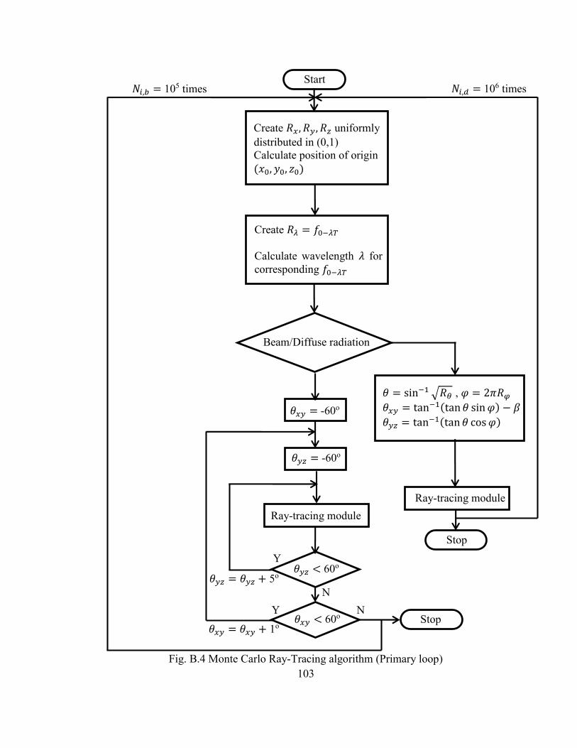
103
Fig. B.4 Monte Carlo Ray-Tracing algorithm (Primary loop)
Create 𝑅𝑥, 𝑅𝑦, 𝑅𝑧 uniformly
distributed in (0,1)
Calculate position of origin
(𝑥0, 𝑦0, 𝑧0)
Create 𝑅𝜆 = 𝑓0−𝜆𝑇
Calculate wavelength 𝜆 for
corresponding 𝑓0−𝜆𝑇
Beam/Diffuse radiation
Stop
𝜃 = sin−1√𝑅𝜃 , 𝜑 = 2𝜋𝑅𝜑
𝜃𝑥𝑦 = tan−1(tan 𝜃 sin𝜑) − 𝛽
𝜃𝑦𝑧 = tan−1(tan 𝜃 cos𝜑)
Start
Ray-tracing module
𝜃𝑦𝑧 < 60o
𝜃𝑥𝑦 < 60o
𝜃𝑥𝑦 = -60o
𝜃𝑦𝑧 = 𝜃𝑦𝑧 + 5o
𝜃𝑦𝑧 = -60o
Ray-tracing module
Stop
Y
N
N
Y
𝜃𝑥𝑦 = 𝜃𝑥𝑦 + 1o
𝑁𝑖,𝑑 = 106 times 𝑁𝑖,𝑏 = 105 times

104
B.3 Implementation of the Specular Error
On account of the surface roughness of the manufactured CPC, the reflection
from the CPC surface will not be perfectly specular. A specular error was defined in the
model to account for the surface roughness. Literature suggests that the angular errors
due to surface roughness have a normal distribution [1, 2].
In the present case, the specular error is defined as the standard deviation of a
distribution of angular errors 𝜃𝑠 between the normal of a perfectly smooth surface, ��, and
the normal of a real surface, ��′ (Fig. B.5). 𝜃𝑠 is thus a normally distributed variable
having a mean 𝜇 = 0 and a standard deviation 𝜎𝑠 specified as the specular error. 𝜃𝑠 can
be find by using the inverse cumulative distribution function (or quantile function) for a
normally distributed variable having a mean of 0 and a standard deviation of 1.
𝜃𝑠 = 𝜎𝑠√2𝑒𝑟𝑓−1(2𝑅𝑒𝑟𝑟,𝑠 − 1) (B.1)
where 𝑒𝑟𝑓−1() is the inverse error function and 𝑅𝑒𝑟𝑟,𝑠 is a generated random number
uniformly distributed in (0,1). It should be noted that 𝜃𝑠 is normalized to ensure values
between 0 and 𝜋 2⁄ only. To define the deviation from the surface normal, the surface
azimuth is required which can take any value from 0 to 2𝜋.
𝜓𝑠 = 2𝜋𝑅𝑒𝑟𝑟,𝜓 (B.2)
Fig. B.5 Modified surface normal to account for specular error
��
��′
𝜃𝑠
𝜓𝑠

105
B.4 Component angles 𝜽𝒙𝒚 and 𝜽𝒚𝒛 of a three dimensional ray
The ray tracing procedure is carried out separately in the 𝑥𝑦 and 𝑦𝑧 planes.
However, incident ray direction from the sun, or from a diffuse isotropic surface (in case
of diffuse radiation) is specified by the polar and azimuth angles. Further, the incidence
angle at the film interface to calculate the film reflectance or to account for the specular
error is also required in 3 dimensions. Once a position is associated with the origin or
destination of the ray, the polar and azimuth angles can be converted into the components
in the 𝑥𝑦 and 𝑦𝑧 planes by considering a local coordinate system (Fig B.6). The y axis is
along the surface normal at the point and z is along the length of the concentrator.
𝜃𝑥𝑦 = tan−1(tan 𝜃 sin𝜓) (B.3)
𝜃𝑦𝑧 = tan−1(tan 𝜃 cos𝜓) (B.4)
A reverse procedure is used to convert the component angles to the polar and
zenith angles according to a global coordinate system.
Fig. B.6 The polar and azimuth angles for a ray in the local coordinate system
𝑥
𝑧
𝑟
𝜃
𝜓
𝑦

106
Appendix C
Results from MCRT
C.1 Hybrid PV/T
Figs. C.1-C.7 → Figs. 2.8 and 2.10
Figs. C.8-C.21 → Fig. 2.10
Figs. C22-C.30 → Fig. 2.9
Fig. C.1 MCRT results for hybrid PV/T: 𝜃𝑐 = 25o, 𝐷 = 0.03m
Fig. C.2 MCRT results for hybrid PV/T: 𝜃𝑐 = 30o, 𝐷 = 0.03m
Fig. C.3 MCRT results for hybrid PV/T: 𝜃𝑐 = 35o, 𝐷 = 0.03m

107
Fig. C.4 MCRT results for hybrid PV/T: 𝜃𝑐 = 40o, 𝐷 = 0.03m
Fig. C.5 MCRT results for hybrid PV/T: 𝜃𝑐 = 45o, 𝐷 = 0.03m
Fig. C.6 MCRT results for hybrid PV/T: 𝜃𝑐 = 50o, 𝐷 = 0.03m
Fig. C.7 MCRT results for hybrid PV/T: 𝜃𝑐 = 55o, 𝐷 = 0.03m

108
Fig. C.8 MCRT results for hybrid PV/T: 𝜃𝑐 = 25o, 𝐷 = 0.02m
Fig. C.9 MCRT results for hybrid PV/T: 𝜃𝑐 = 30o, 𝐷 = 0.02m
Fig. C.10 MCRT results for hybrid PV/T: 𝜃𝑐 = 35o, 𝐷 = 0.02m
Fig. C.11 MCRT results for hybrid PV/T: 𝜃𝑐 = 40o, 𝐷 = 0.02m

109
Fig. C.12 MCRT results for hybrid PV/T: 𝜃𝑐 = 45o, 𝐷 = 0.02m
Fig. C.13 MCRT results for hybrid PV/T: 𝜃𝑐 = 50o, 𝐷 = 0.02m
Fig. C.14 MCRT results for hybrid PV/T: 𝜃𝑐 = 55o, 𝐷 = 0.02m
Fig. C.15 MCRT results for hybrid PV/T: 𝜃𝑐 = 25o, 𝐷 = 0.025m

110
Fig. C.16 MCRT results for hybrid PV/T: 𝜃𝑐 = 30o, 𝐷 = 0.025m
Fig. C.17 MCRT results for hybrid PV/T: 𝜃𝑐 = 35o, 𝐷 = 0.025m
Fig. C.18 MCRT results for hybrid PV/T: 𝜃𝑐 = 40o, 𝐷 = 0.025m
Fig. C.19 MCRT results for hybrid PV/T: 𝜃𝑐 = 45o, 𝐷 = 0.025m

111
Fig. C.20 MCRT results for hybrid PV/T: 𝜃𝑐 = 50o, 𝐷 = 0.025m
Fig. C.21 MCRT results for hybrid PV/T: 𝜃𝑐 = 55o, 𝐷 = 0.025m
Fig. C.22 MCRT results for hybrid PV/T: 𝜃𝑐 = 25o, 𝐷 = 0.03m, 𝐶𝑒 = 1.4
Fig. C.23 MCRT results for hybrid PV/T: 𝜃𝑐 = 25o, 𝐷 = 0.03m, , 𝐶𝑒 = 1.7

112
Fig. C.24 MCRT results for hybrid PV/T: 𝜃𝑐 = 30o, 𝐷 = 0.03m, 𝐶𝑒 = 1.4
Fig. C.25 MCRT results for hybrid PV/T: 𝜃𝑐 = 30o, 𝐷 = 0.03m, 𝐶𝑒 = 1.7
Fig. C.26 MCRT results for hybrid PV/T: 𝜃𝑐 = 35o, 𝐷 = 0.03m, 𝐶𝑒 = 1.4
Fig. C.27 MCRT results for hybrid PV/T: 𝜃𝑐 = 40o, 𝐷 = 0.03m, 𝐶𝑒 = 1.2

113
Fig. C.28 MCRT results for hybrid PV/T: 𝜃𝑐 = 40o, 𝐷 = 0.03m, 𝐶𝑒 = 1.4
Fig. C.29 MCRT results for hybrid PV/T: 𝜃𝑐 = 45o, 𝐷 = 0.03m, 𝐶𝑒 = 1.2
Fig. C.30 MCRT results for hybrid PV/T: 𝜃𝑐 = 50o, 𝐷 = 0.03m, 𝐶𝑒 = 1.2

114
C.2 Hybrid Solar Window
Figs. C.31-C.35 → Vertical window
Figs. C.36-C.40 → Horizontal skylight
Fig. C.31 MCRT results for vertical window: 𝜃𝑐 = 25o, 𝐷 = 0.016m
Fig. C.32 MCRT results for vertical window: 𝜃𝑐 = 30o, 𝐷 = 0.016m
Fig. C.33 MCRT results for vertical window: 𝜃𝑐 = 35o, 𝐷 = 0.016m

115
Fig. C.34 MCRT results for vertical window: 𝜃𝑐 = 40o, 𝐷 = 0.016m
Fig. C.35 MCRT results for vertical window: 𝜃𝑐 = 45o, 𝐷 = 0.016m
Fig. C.36 MCRT results for horizontal skylight: 𝜃𝑐 = 25o, 𝐷 = 0.016m
Fig. C.37 MCRT results for horizontal skylight: 𝜃𝑐 = 30o, 𝐷 = 0.016m

116
Fig. C.38 MCRT results for horizontal skylight: 𝜃𝑐 = 35o, 𝐷 = 0.016m
Fig. C.39 MCRT results for horizontal skylight: 𝜃𝑐 = 40o, 𝐷 = 0.016m
Fig. C.40 MCRT results for horizontal skylight: 𝜃𝑐 = 45o, 𝐷 = 0.016m

117
Appendix D
Additional notes on the thermal model
D.1 Convective heat transfer within the CPC cavity
Due to the non-standard shape of the CPC cavity, it is modeled as an annular
region between eccentric horizontal cylinders. The overall mean convective heat transfer
from the cylindrical absorber is calculated using correlations developed by Kuehn and
Goldstein [1] for the conduction, laminar boundary-layer flow, and turbulent boundary-
layer flow regimes. The correlation is valid for Rayleigh numbers upto 1010 and a wide
range of Prandtl numbers. The Nusselt number for the convection part is given by
𝑁𝑢𝐷,𝑐𝑜𝑛𝑣 =2
ln(1+2 𝑁𝑢𝑖
⁄
1+2 𝑁𝑢𝑜⁄
)
(D.1)
where
𝑁𝑢𝑖 = {[0.518𝑅𝑎𝐷1
4𝑓2(𝑃𝑟)]15
+ (0.1𝑅𝑎𝐷1
3)15
}
1
15
(D.2)
𝑁𝑢𝑜 =
(
{[(2
1−𝑒−14
)
5
3+ [0.587𝑓3(𝑃𝑟)𝑅𝑎𝐷𝑜
1
4]
5
3]
3
5
}
15
+ (0.1𝑅𝑎𝐷𝑜1
3)15
)
1
15
(D.3)
with
𝑓2(𝑃𝑟) = [1 + (0.559
𝑃𝑟)
3
5]
−5
12
(D.4)
𝑓3(𝑃𝑟) = [(1 +0.6
𝑃𝑟0.7)−5
+ (0.4 + 2.6𝑃𝑟0.7)−5]−1
5
(D.5)

118
For the conduction part, which is dominant as Rayleigh number approaches zero, the
Nusselt number is given by
𝑁𝑢𝐷,𝑐𝑜𝑛𝑑 =2
cosh−1{[𝐷2+𝐷𝑜2−(𝐷𝑜−𝐷)2��2]/2𝐷𝐷𝑜}
(D.6)
𝜖 is the eccentricity of the cylinders normalized with respect to (𝐷𝑜−𝐷
2). The overall
Nusselt number based on the absorber tube diameter is given by
𝑁𝑢𝐷 = [(𝑁𝑢𝐷,𝑐𝑜𝑛𝑣)15+ (𝑁𝑢𝐷,𝑐𝑜𝑛𝑑)
15]
1
15 (D.7)
The effective diameter 𝐷𝑜 is taken to be equal to the length of the major axis of the CPC,
either the height or the width. The center of the outer cylinder is fixed graphically to
approximate the shape of the CPC. An example of the approximation procedure is shown
in Fig. D.1.
Fig. D.1 The absorber tube and the CPC cavity approximated as eccentric cylinders
𝐷𝑜 = 𝑊
𝜖
𝑊

119
The convective heat transfer coefficient from the absorber to the cover, ℎ𝑐,𝑎−𝑐,
and from the absorber to the CPC, ℎ𝑐,𝑎−𝑚, are then calculated using equation (C.8) and
(C.9). An empirical factor, 𝑓𝑟𝑎𝑡 for CPC geometries of different concentrations from 1.56
to 4.13, with an inclination of up to 30o is proposed in [2]. A value of 0.55 is used for 𝑓𝑟𝑎𝑡
for the present case. The maximum inclination of the geometries used for the present
study is 45o and the assumption of the validity of 𝑓𝑟𝑎𝑡 for this case is likely to create some
uncertainty in the results.
ℎ𝑐,𝑎−𝑚
ℎ𝑐,𝑎−𝑐= 𝑓𝑟𝑎𝑡 (D.8)
ℎ𝑐,𝑎−𝑐 =𝑁𝑢𝐷𝑘
𝐷(
1
1+𝑓𝑟𝑎𝑡) (D.9)
While calculating the U-factor of the window (Section 3.4.3), the absorber tube is
considered to be in thermal equilibrium with the surrounding air in the cavity. In this
case, the CPC is considered to be a vertical cavity having an effective gap thickness 𝑑𝑔
equal to 90% of the maximum gap thickness. Based on a Rayleigh number for the gap
thickness of the vertical cavity,
𝑁𝑢 = (𝑁𝑢1, 𝑁𝑢2)𝑚𝑎𝑥 (D.10)
𝑁𝑢1 = 0.0673838𝑅𝑎13⁄ 5×10⁴ < 𝑅𝑎 (D.11)
𝑁𝑢1 = 0.028154 𝑅𝑎0.4134 104< 𝑅𝑎 ≤ 5×10⁴ (D.12)
𝑁𝑢1 = 1 + 1.7596678E-10 𝑅𝑎2.2984755 𝑅𝑎 ≤ 104 (D.13)
𝑁𝑢2 = 0.242 (𝑅𝑎
𝐻𝑤 𝑑𝑔⁄)0.272
(D.14)
where 𝐻𝑤 is the height of the window.

120
D.2 Radiative heat transfer within the CPC cavity
The radiative heat transfer coefficients from the absorber tube to the CPC
reflector and the cover, and from the reflector to the cover are derived in [4], based on the
CPC geometry, possibility of multiple reflection events, and the optical properties of the
cover, absorber and the reflector material. The effective emissivities for radiative heat
transfer between different components are given by -
휀𝑎−𝑐 =𝑎 𝑐𝜌𝑚
𝑛𝑖
1−𝜌𝑚2𝑛𝑖𝜌𝑎𝜌𝑐
(B.10)
휀𝑎−𝑚 =1−𝜌𝑚
𝑛𝑖𝜌𝑐
1−𝜌𝑚2𝑛𝑖𝜌𝑎𝜌𝑐
(1 − 𝜌𝑚𝑛𝑖)휀𝑎 (B.11)
휀𝑚−𝑐 = 휀 𝑐 [1+𝜌𝑚
𝑛𝑖𝜌𝑎
1−𝜌𝑚2𝑛𝑖𝜌𝑎𝜌𝑐
(1 − 𝜌𝑚𝑛𝑖) +
1−𝜌𝑚𝑛𝑜
1−𝜌𝑚𝑛𝑖𝜌𝑐
(𝐴𝑐−𝐴𝑎
𝐴𝑎)] (B.12)
𝑛𝑖 represents is the average number of reflections a ray undergoes when it is launched
into the CPC within the CPC acceptance angle. 𝑛𝑜 is the average number of reflections
when a ray is launched into the CPC at an angle outside the acceptance angle. Both these
quantities are obtained from Mote Carlo ray-tracing for each geometry. The properties of
the cover, absorber tube and the wavelength selective film on acrylic for the infrared
spectrum are listed in Table B.1.
Table B.1 Optical properties of the CPC components for re-radiation in the IR
휀 𝜌 𝜏 Cover 0.84 0.11 0.05
CPC/Selective film 0.85 0.12 0.03
Absorber 0.1 0.9 0

121
D.3 Thermophysical properties of working fluids
Air [5]
1. Thermal conductivity (W/mK)
𝑘 = -2.276501E-3 + 1.2598485E-4T – 1.4815235E-7T2 + 1.73550646E-10T3 –
1.066657E-13T4 + 2.47663035E-17T5
2. Specific heat capacity (kJ/kg-K)
𝑐𝑝 = 1.03409 – 0.284887E-3T + 0.7816818E-6T2 – 0.4970786E-9T3 + 0.1077024E-
12T4
3. Dynamic viscosity (Ns/m2)
𝜇 = -9.8601E-1 + 9.80125E-2T – 1.17635575E-4T2 + 1.2349703E-7T3 –
5.7971299E-11T4
The density of air was calculated from the ideal gas law at atmospheric pressure.
Ethylene glycol (40% v/V) aqueous solution [6]
1. Thermal conductivity (W/mK)
𝑘 = -0.2581 + 0.0037T – 5e-6T2
2. Specific heat capacity (kJ/kg-K)
𝑐𝑝 = 2486.9 + 3.3498T

122
References
[1] Kuehn, T. H., Goldstein, R. J., 1976, “Correlating Equation for Natural Heat Transfer
between Horizontal Circular Cylinders,” Int. J. Heat Mass Transfer, Vol. 19, pp. 1127-
1134
[2] Prapas, D. E., Norton, B., and Probert, S. D., 1987, "Thermal Design of Compound
Parabolic Concentrating Solar-Energy Collectors," Journal of Solar Energy
Engineering,109(2), pp.161-168.
[3] Wright, J.L., 1996. A Correlation to Quantify Convective Heat Transfer Between
Vertical Window Glazings. 102, Pt. 1, 940-946.
[4] Rabl, A., 1976, "Optical and Thermal Properties of Compound Parabolic
Concentrators," Solar Energy, 18(6), pp. 497-511.
[5] Rohsenow, W. M., Hartnett, J. P., Cho, Y. I., 1998, Handbook of Heat Transfer, Third
Edition, McGraw-Hill Professional Publishing
[6] WEBA Technology, Glycol Based Heat Transfer Fluid Technical Manual,
http://www.webacorp.com/HTF-Manual.pdf, last accessed 5/1/2013

123
Appendix E
Uncertainty Analysis
This appendix provides the uncertainty in measured and calculated quantities,
including both bias and precision error. The Root-Sum-of-Squares (RSS) [1] method was
used for calculating the propagation of error in calculated quantities, resulting from
individual measurements 𝑥𝑖. Let 𝑅 be a calculated quantity that is a function of 𝑛
measured quantities, 𝑥𝑖 having an uncertainty ∆𝑥𝑖.
𝑅 = 𝑓(𝑥1, 𝑥2, … , 𝑥𝑛) (E.1)
The uncertainty in the calculated quantity is given by
∆𝑅 = √∑ 𝜃𝑖∆𝑥𝑖𝑛𝑖=1 (E.2)
𝜃𝑖 =𝜕𝑅
𝜕𝑥𝑖 (E.3)
Measured quantities
All instrument output signals were measured using a Agilent 34970A Data
Acquisition Unit. The has an accuracy of ±0.0035% of the reading + 0.0005% of the
range for voltage measurement, which is negligible in comparison to the uncertainty in
the instruments. Table E.1 lists the uncertainty in difference measured variables. Table
E..2 lists the uncertainty in thermophysical properties of the fluid due to the uncertainty
in measurement of temperature. Table E.3 lists the uncertainty in quantities calculated
from the measured variables.
References
[1] Figliola, R. S., Beasley, D. E., 1995, Theory and Design for Mechanical
Measurements, Second Edition, John Wiley and Sons, New York, NY.
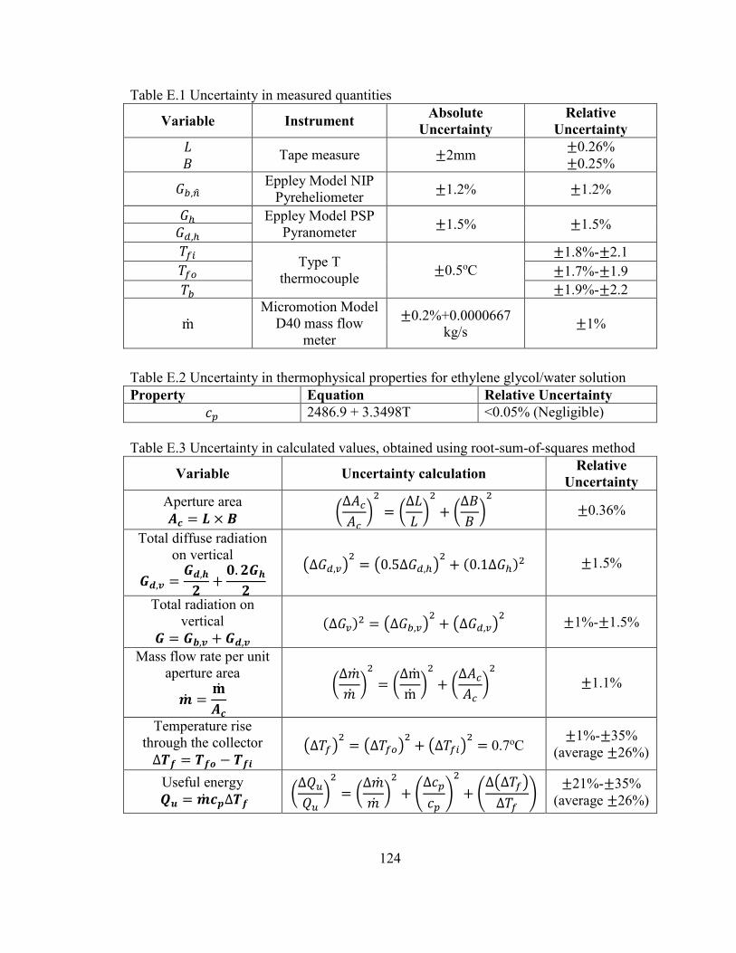
124
Table E.1 Uncertainty in measured quantities
Variable Instrument Absolute
Uncertainty
Relative
Uncertainty
𝐿
𝐵 Tape measure ±2mm
±0.26%
±0.25%
𝐺𝑏,�� Eppley Model NIP
Pyreheliometer ±1.2% ±1.2%
𝐺ℎ Eppley Model PSP
Pyranometer ±1.5% ±1.5%
𝐺𝑑,ℎ
𝑇𝑓𝑖 Type T
thermocouple ±0.5oC
±1.8%-±2.1
𝑇𝑓𝑜 ±1.7%-±1.9
𝑇𝑏 ±1.9%-±2.2
m
Micromotion Model
D40 mass flow
meter
±0.2%+0.0000667
kg/s ±1%
Table E.2 Uncertainty in thermophysical properties for ethylene glycol/water solution
Property Equation Relative Uncertainty
𝑐𝑝 2486.9 + 3.3498T <0.05% (Negligible)
Table E.3 Uncertainty in calculated values, obtained using root-sum-of-squares method
Variable Uncertainty calculation Relative
Uncertainty
Aperture area
𝑨𝒄 = 𝑳 × 𝑩 (∆𝐴𝑐𝐴𝑐)2
= (∆𝐿
𝐿)2
+ (∆𝐵
𝐵)2
±0.36%
Total diffuse radiation
on vertical
𝑮𝒅,𝒗 =𝑮𝒅,𝒉𝟐+𝟎. 𝟐𝑮𝒉𝟐
(∆𝐺𝑑,𝑣)2= (0.5∆𝐺𝑑,ℎ)
2+ (0.1∆𝐺ℎ)
2 ±1.5%
Total radiation on
vertical
𝑮 = 𝑮𝒃,𝒗 + 𝑮𝒅,𝒗 (∆𝐺𝑣)
2 = (∆𝐺𝑏,𝑣)2+ (∆𝐺𝑑,𝑣)
2 ±1%-±1.5%
Mass flow rate per unit
aperture area
�� =𝐦
𝑨𝒄
(∆��
��)2
= (∆m
m)2
+ (∆𝐴𝑐𝐴𝑐)2
±1.1%
Temperature rise
through the collector
∆𝑻𝒇 = 𝑻𝒇𝒐 − 𝑻𝒇𝒊 (∆𝑇𝑓)
2= (∆𝑇𝑓𝑜)
2+ (∆𝑇𝑓𝑖)
2= 0.7oC
±1%-±35%
(average ±26%)
Useful energy
𝑸𝒖 = ��𝒄𝒑∆𝑻𝒇 (∆𝑄𝑢𝑄𝑢)2
= (∆��
��)2
+ (∆𝑐𝑝
𝑐𝑝)
2
+ (∆(∆𝑇𝑓)
∆𝑇𝑓)
±21%-±35%
(average ±26%)