bts cabling 2
TRANSCRIPT

ESMA 1
ESMA 2
TRX 1 & 2 EXGA
TRX 3 & 4 EXGA
TRX 5 & 6 EXGA
TRX 1 & 2 EXDA
TRX 3 & 4 EXDA
TRX 5 & 6 EXDA
TRX 7 & 8 EXDA
TRX 9 & 10 EXDA
TRX 11 & 12 EXDA
DDU ERGA SEC.1
DDU ERGA SEC.2
DDU ERGA SEC.3
DDU ERDA SEC.1
DDU ERDA SEC.2
DDU ERDA SEC.3
SPACE
SPACE
SPACE
SPACE
BTS OUTDOOR CABINET
GSM 900
SECTOR 1 GSM900
SECTOR 2 GSM900
SECTOR 3 GSM900
SECTOR 1 DCS1800
SECTOR 2 DCS1800
SECTOR 3 DCS1800DCS 1800
2+2+2 GSM900 – 4+4+4 DCS1800 CONFIG.

TXA TX OUT TXB
DP WBC
RX A RX DIV RX B RX DIV TX A TX B
BUS ERXA PWR DP
EXDA/EXGA DTRX

Dual TRX Module (EXxA)The Dual TRX Module (EXxA) is a two-carrier TRX unit. The modulecontains the common (2 carrier) baseband part and two separate RF partsfor two transceivers (transmitter and receiver chains) and space for twooptional Wideband Combiner Modules.The Dual TRX Module is used as:. a combined module with the Dual Duplexer Module (ERxA), makinga logical Sector Module. or a stand-alone TRX module with the Remote Tune Combiner(ECxA) Module. or a stand-alone extension TRX module.The Dual TRX Module and System Module (ESMA) communication ismanaged through a single Ethernet interface. Each transceiver within theDual TRX Module can be separately activated with a licence key at theBSC.The Dual TRX Module contains two transceivers that can be used:. as a separate TRX in the same sector. as a separate TRX in different sectors. or as a Double Power TRX.There are separate Dual TRX Modules for each frequency band that NokiaFlexi EDGE BTS supports:. EXTA – GSM800. EXGA – GSM900. EXDA – GSM1800. EXPA – GSM1900

TXA ExtA RXAO RXAI RXA1 RXA2 RXA3 RXA4 RXB1 RXB2 RXB3 RXB4 ExtB TXB ANT B ANT A
ERXX / DDU UNIT
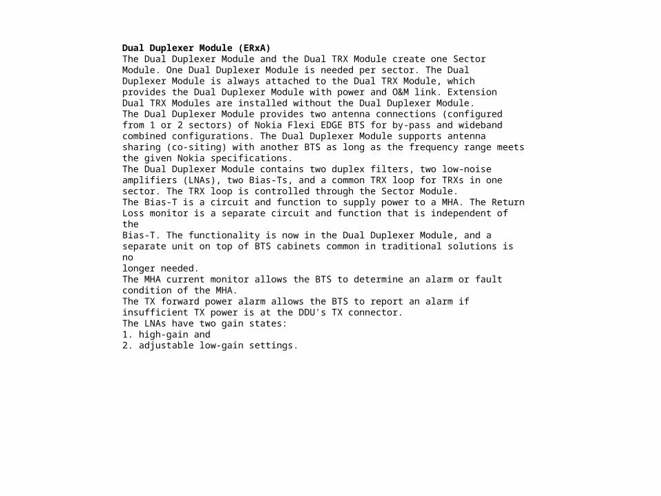
Dual Duplexer Module (ERxA)The Dual Duplexer Module and the Dual TRX Module create one SectorModule. One Dual Duplexer Module is needed per sector. The DualDuplexer Module is always attached to the Dual TRX Module, whichprovides the Dual Duplexer Module with power and O&M link. ExtensionDual TRX Modules are installed without the Dual Duplexer Module.The Dual Duplexer Module provides two antenna connections (configuredfrom 1 or 2 sectors) of Nokia Flexi EDGE BTS for by-pass and widebandcombined configurations. The Dual Duplexer Module supports antennasharing (co-siting) with another BTS as long as the frequency range meetsthe given Nokia specifications.The Dual Duplexer Module contains two duplex filters, two low-noiseamplifiers (LNAs), two Bias-Ts, and a common TRX loop for TRXs in onesector. The TRX loop is controlled through the Sector Module.The Bias-T is a circuit and function to supply power to a MHA. The ReturnLoss monitor is a separate circuit and function that is independent of theBias-T. The functionality is now in the Dual Duplexer Module, and aseparate unit on top of BTS cabinets common in traditional solutions is nolonger needed.The MHA current monitor allows the BTS to determine an alarm or faultcondition of the MHA.The TX forward power alarm allows the BTS to report an alarm ifinsufficient TX power is at the DDU's TX connector.The LNAs have two gain states:1. high-gain and2. adjustable low-gain settings.
PWR 1
PWR 2
PWR 3
PWR 4
PWR 5
PWR 6
BUS 1
BUS 2
BUS 3
BUS 4
BUS 5
BUS 6
EAC
SYNC OUT
SYNC IN
PWR -48V
PWR +48V
FIFA
FB 1
FB 2
SS
FPA
Q1
LMP
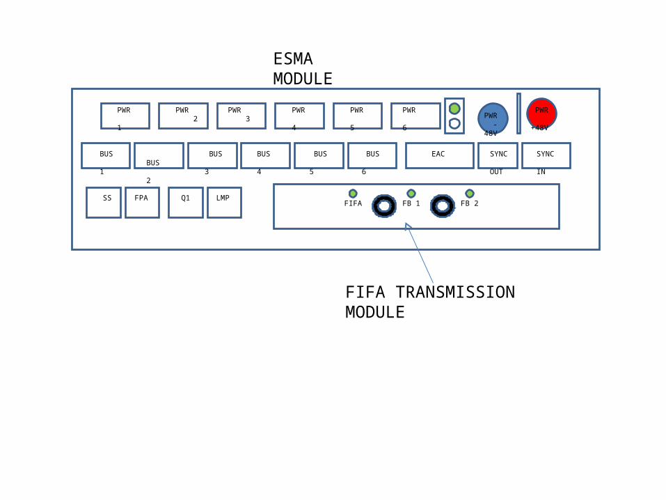
ESMA MODULE
FIFA TRANSMISSION MODULE

Nokia Flexi EDGE System Module(ESMA)The System Module is a unit providing BTS common functionalities andexternal and internal connections for the whole BTS. The BTS software isstored in the System Module.The System Module also receives and stores the unit identificationinformation of all other units of the BTS. The System Module supportsconfigurations of up to 12 TRXs. For larger configurations, the SystemExtension Module is used.The main functions of the System Module are:. BTS O&M. BTS integrated transport. Module bus control and BTS synchronisation. Power distribution (48 VDC) to other modulesSee the following figure for an isometric view of the System Module

IF CABLE FB2
FIFA MODULE
SECTOR 1 GSM 900
SECTOR 2 GSM 900
SECTOR 3 GSM 900
TRX 1 &2 EXGA
DDU ERGA
TRX 3 &4 EXGA
TRX 5 &6 EXGA
DDU ERGA
DDU ERGA
2+2+2 GSM 900 CABLING
IF CABLE FB1
ANTENNA A SEC 1
ANTENNA A SEC 2
ANTENNA A SEC 3
ANTENNA B SEC 1
ANTENNA B SEC 2
ANTENNA B SEC 3
DCV -48
DCV +48
ESMA 1

IF CABLE FB2
SECTOR 1 DCS 1800
SECTOR 2 DCS 1800
SECTOR 3 DCS 1800
TRX 1 &2 EXDA
DDU ERDA
TRX 5 & 6 EXDA
TRX 11 & 12 EXDA
DDU ERDA
DDU ERDA
4+4+4 DCS 1800 CABLING
IF CABLE FB1
ANTENNA A SEC 1
ANTENNA A SEC 2
ANTENNA A SEC 3
ANTENNA B SEC 1
ANTENNA B SEC 2
ANTENNA B SEC 3
DCV -48
DCV +48
ESMA 2
TRX 9 & 10 EXDA
TRX 7 & 8 EXDA
TRX 3 & 4 EXDA