multistandard bts outdoor mbo main features - … 2.pdf · multistandard bts outdoor mbo main...
TRANSCRIPT

1
MultistandardMultistandard BTS Outdoor MBO BTS Outdoor MBO Main FeaturesMain Features
Cabinet extendible on site (1-door to 2-doors.)
Front access to BTS equipment only
Number of antennas: ≤ 6 (3 sect.) in MBO1, ≤ 12 (6 sectors) in MBO2
Full variety of options (BBU, MW, REK, TMA, CrossConn, etc.)
3-phase or 1-phase AC mains
Temp. maintained by air/air heat exchanger and heaters
Types of Cabinet and Configurations
Height: total 1485mm,
Width : total MBO1 903mm, total MBO2 1520mm,
Depth: total 747mm
MBO1 - Multi Standard BTS Outdoor 1-door
up to 8 TRE GSM (1x8, 2x4, 3x 2 ) in 4 subracks
MBO2 - Multi Standard BTS Outdoor 2-doors
up to 12 TRE GSM ( 2x6, 3x4 ) in 7 subracks

2
MultistandardMultistandard BTS Outdoor MBO BTS Outdoor MBO MBO1 and MBO2 CharacteristicsMBO1 and MBO2 Characteristics
BATTERY saving features
One TRX “full power” + others “60% power”
Automatic Shutdown
Keeps BCCH TRX alive
Configurable timer to start operating
Example of battery times:
MBO2 - S4,4,4 - one BU90 (multiply the time up to 3xBU)“Auto shutdown” not enable ⇒ 120 min (2h)“Auto shutdown” enable (timer set to 0 min) ⇒ 340 min (5.6h)“Auto shutdown” enable (timer set to 150 min) ⇒ 240 min (4h)

3
BSC
BTSMW-IDU
MW-ODU
Wide floor space SolutionX
Alcatel EVOLIUM™solution
BTS
ANIDU
IDU
SUM
Optimizing BTS site constraintsOptimizing BTS site constraintsEVOLIUM™ integrated microwaveEVOLIUM™ integrated microwave

4
TRXThe dimensioning of the TRX is done according to the profile of the subscriber that will use the voice and data (GPRS) channels. The amount of each group of subscribers and the type of adopted signaling (normal, high or very high) is also considered.
Network Elements Network Elements TRX Configuration (BSS)TRX Configuration (BSS)

5
Site
Setor A
Setor BSetor C
SiteThe site dimensioning is done according to the quantity of sectors and the amount of BTS's. The configuration of theBTS’s depends on the quantity of TRX. The BTS has a limitation regarding the quantity of the TRX not only because of the hardware limitation but also because of the bandwidth available.
Network Elements Network Elements Site Configuration (BSS)Site Configuration (BSS)

6
TheThe EvoliumTM EvoliumTM BSC differenciationBSC differenciationReducing the O&M costReducing the O&M cost
Advanced and compact platformScalable and flexible to meet all network requirements
Efficient resource usage on Air, Abis and Ater interfaces
Allowing optimized investment strategyLow start-up cost
High growth potential to meet traffic requirements
Support of more than 144,000 BHCA (busy hour call attempts)
No hardware upgrade for GPRS
Intelligent and flexible call handlingEnhanced Full Rate - Adaptive Multi Rate
Advanced algorithms for hierarchical and multiband networks
32-128TRX 192-288TRX 352-448TRX

7
Access Network (BTS-BSC)topology
multidrop
chain
loop
star
meshed
BSC
Network Elements Network Elements BSC Configuration (BSS)BSC Configuration (BSS)

8
BSC
Network Elements Network Elements BSC Configuration (BSS)BSC Configuration (BSS)
BSC configurationNumber of BTS
Number of Cells
Number of TRXs
CODEC to be used
Traffic
A / Ater mux interface PCM
Abis Interface PCM
Number 7 signaling channels
Topology

9
Network Elements Network Elements BSC Configuration (BSS)BSC Configuration (BSS)
BSC capacity

10
BTSSatellite
Built-in EVOLIUM™ Microwaveor
EVOLIUM™ LMDS
BTS
Leased LineBTS
Transmission with EVOLIUM™ BSSTransmission with EVOLIUM™ BSS
BSC
Few km Tens of km Hundreds of km
Distance from BSC
BSC hub
HDSL
BTS

11
A new generation TC With built-in high-performance for maximum capacity
Capacity
Sized to your current need with support for more capacity as your network growths
192 A itf (48 Ater mux) capacity, ie up to 5600 Erl per TC rack
Compactness
Compact equipment practice : 19” standard rack - only 2m height
Unrival compactness with only 3.75 liters per A interface
Flexibility
Rack sharing feature
Multiple BSCs connection simplifies your network design
EVOLIUM™ Compact TCEVOLIUM™ Compact TCThe new standard for The new standard for transcoderstranscoders

12
TC
A925 TranscoderA925 TC has capacity for 4subracks of up to 12 MT120 boards each, in a total of up to 48 MT120 boards for each rack. A925 TC can transport data of up to 24 BCS'staking into account the minimum of two connected MT120 boards to each BSC.
MT120Ater
4 x A
MT120Ater
4 x A
MT120Ater
4 x A
Up to 48 boards
Network Elements Network Elements Transcoder Transcoder Configuration (BSS)Configuration (BSS)

13
MFS
Network ElementsNetwork ElementsMFS Configuration (BSS)MFS Configuration (BSS)
A935 MFS• GPRS (General Packet Radio Service)•Data transmission based on packet Swithching instead of Circuit Swithcing• Mail, Internet Browsing (Web Surfers), etc• No end-to-end connection requirement,
no channel individual allocation, sharedresources between users
14
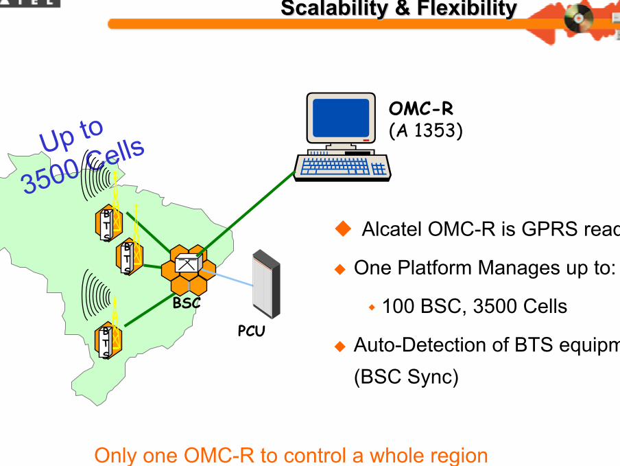
EVOLIUM™ OMCEVOLIUM™ OMC--R R High Capacity, High Capacity, Scalability & FlexibilityScalability & Flexibility
Only one OMC-R to control a whole region
Up to
3500 Cells
BTS
BSC
BTS
BTS
PCU
OMC-R (A 1353)
Alcatel OMC-R is GPRS ready
One Platform Manages up to:
100 BSC, 3500 Cells
Auto-Detection of BTS equipment(BSC Sync)

15
Frame Relay
SGSNGGSN
GPRSBackbone
DNS/DHCP
OMC-G
Charging Gateway
GPRS Interception
Node
Other PLMNGPRS
Backbone
Border Gateway
W@P Server
NSS GPRS
VoiceDataMixedSignaling
MFS
BTS
OMC-R
TCBSC
BSS
BTS
Mobileand/or
fixed stations HLR/AuC INTERNETSMS C
Voice Mail
EIR
OMC-SPSTN
MSC/VLR
SS7IN
CC&B
SS7Other PLMN
NSS
Alcatel EvoliumAlcatel EvoliumEndEnd--toto--End Solution : TopologyEnd Solution : Topology

16
EvoliumEvolium MSC MSC –– E 10 E 10
No loss of air time with high peaksTop quality service, non stop
Best-in-class capacity and performance
From 2.5K to 1,000K subs (2M*)From 36 up to 800K BHCA (8M*)From 16 up to 2,048 PCM (16K*)
A vast array of features
High revenue generation
Lowest OPEX on the marketLow foot print: Up to 17 racks (400K subs)
Low consumption: Max 24K Watts
Smooth evolution towards 3G solutions
Alcatel Evolium™ MSC
MSC today

17
Alcatel MSC/VLR ArchitectureAlcatel MSC/VLR Architecture
A1000 E10 MMSSP
IWF
Alcatel Evolium®MSC/VLR
BSS
n x E1 (ISUP)m x E1
(A Interface)
PSTN/ISDN
HLR/AuCA8360
4 x E1 (MAP)
k x E14 x E1INAP
With Echo CancellerBSC
BTS
BTS
BSC
BTS
BTS
BTS
BTS
BTS
RCP/VLRA1421
Other Devices:
CDR (Call Detail Record)/File Collector
EIR (Equipment Identity Register)
SMSC (Short Message Service Center)
VMS (Voice Mail Server)
Up to 2 Million SubscribersSTM-1 InterfacesUp to 4 RCPLow consuption 1,3kW per RackLess than 22 Racks total (SSP+RCP+IWF)RCX/RCH TechnologiesMobile and Fixed Subscribers

18
Alcatel EvoliumAlcatel Evolium Network ManagementNetwork ManagementNMC 2 NMC 2
Traffic Management
Common Desktop
Common Alarm ListHW Equipment
Views
A1000E10 NBFixed and Mobile A1000E10 MM
DCNX.25 / IP
A1000 NSSHLR
•Supervision of Alarms, Elimination of malfunctions, Performance Management, Security Management
•Creating Subscriptions, Delating Subscriptions, Collecting Charging Tickets.

19
Agenda:GSM Key Features
GSM System Architecture
BSS Subsystem
NSS Subsystem
Design Considerations
Dimmensioning (Cells, Traffic, Users)
Spectrum and Coverage
Conclusions
AGENDAAGENDA
Design Considerations

20
Network DesignNetwork Design
Interfaces
21
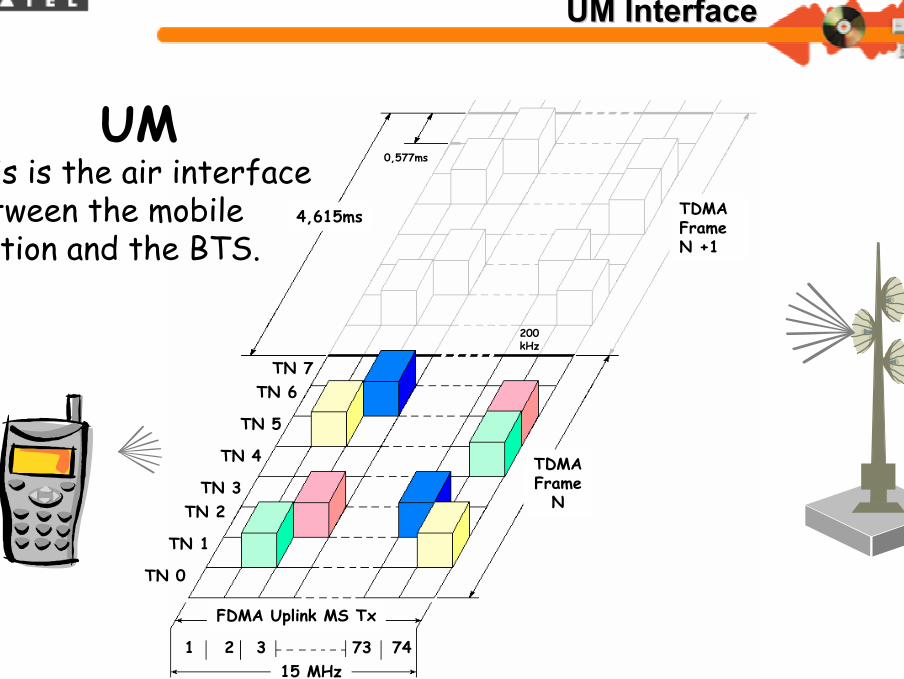
Network InterfacesNetwork InterfacesUM InterfaceUM Interface
TN 7
1 2 3
TDMA Frame N +1
1710 MHz
73
1725 MHz
0,577ms
4,615ms
200kHz
74
TN 6
TN 5
TN 4
TN 3TN 2
TN 1
TN 0
TDMA Frame
N
FDMA Uplink MS Tx
15 MHz
UMThis is the air interface between the mobile station and the BTS.

22
Network InterfacesNetwork InterfacesUM InterfaceUM Interface
UM DimensioningDual Rate total mobile penetrationTRAFFIC VOLUME per subscriber (in mErl)Number of subscriber per cellTRAFFIC BLOCKING probability
GPRS ParametersType of Services (Business, Consumer, …)Number of users per type of serviceData Volume per user per Busy Hour (kbits)Throughput per service

23
Optional!!!Signaling Parameters at the Busy Hour
CALL attempt (Mobile Originated)CALL attempt (Mobile Terminated)Short Message Services (Mobile Originated)Short Message Services (Mobile Terminated)LOCATION UPDATEIMSI ATTACHIMSI DETACH
Network InterfacesNetwork InterfacesUM Interface UM Interface -- SignalingSignaling

24
BSC
UM
Abis
MobileStation
BTSE1
TRX A
TRX B
TRX C
AbisThe Abis link can be configured to use different schemes of multiplexing that finds the optimized occupancy of the link. The figure shows a sample of multiplex usage on theAbis link
Network InterfacesNetwork InterfacesAbis Abis InterfaceInterface

25
BSC
AbisBTS
E1
TRX CTRX A
TRX B RSL
OML
AbisThe dimensioning of the Abis link is done according to the quantity of TRX, BTS'scabinets, cells and the type of multiplex used on the signaling. The usage of some features will also impact on the dimensioning of the Abis link. The following table shows just an example of occupancy on the Abis link.
Network InterfacesNetwork InterfacesAbis Abis DimensioningDimensioning

26
TC
A MSC
PSTN
BSC
4 x E1
Ater
Channels occupancy N7
N7
1 x E1
0 16
0 16
Network InterfacesNetwork InterfacesAter mux Ater mux & A Interface& A Interface

27
TC
A
MSC4 x E1
N70 16
A InterfaceThe calculation of the PCM’s links used for the A interface is done according to the traffic generated by the BTS taking into account the busy channels only using the Erlang B law. The table shown presents an example of traffic capacity using Blocking Rate of 0.1%.
Network InterfacesNetwork InterfacesA Interface DimensioningA Interface Dimensioning

28
TC
A MSC
PSTN
BSC
4 x E1
Ater
Channels occupancy N7
N7
1 x E1
0 16
0 16
AterThe Ater interface is the A interface multiplexed by 4:1.
Network InterfacesNetwork InterfacesAter mux Ater mux DimensioningDimensioning
29
MFS
TC
Ater
BSC
E1
Ater
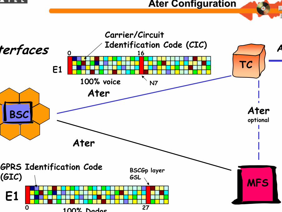
BSCGp layerGSL
100% Dados
GPRS Identification Code (GIC)
Interfaces
Ateroptional
N7
Carrier/Circuit Identification Code (CIC)
100% voiceE1
0 16
0 27
A
Network Interface Network Interface AterAter ConfigurationConfiguration

30
Ex.: 25% Voice + 75% GPRS
MFS
TC
A
BSC
Ater
Interfaces
CIC GIC
CIC
SGSN
INTERNET
Gb(Frame Relay)
Ater
Network Interface Network Interface AterAter ConfigurationConfiguration

31
Dimensioning examples:
Network Interfaces Dimensioning (BSS)Network Interfaces Dimensioning (BSS)

32
Network DesignNetwork Design
Coverage, Traffic andDesign Parameters

33
Acquiring:Maps ( compulsory)Aerial pictures ( optional)Digital database
(optional: used for Radio planning)
Coverage IssuesCoverage Issues

34
Gathering all information about the existing sites:Coordinates
Coverage area of each sector
Antenna heights
Infrastructure availableAntenna tower
Rooftop / Greenfield
Energy...
CoverageCoverageExisting Network (BSS)Existing Network (BSS)

35
CoverageCoverageGeographical ModelingGeographical Modeling
Land UsageDense Urban,
Urban,
Suburban,
Residential,
Industrial,
Forest,
Village,
Open area,...

36
CoverageCoverageService RequirementService Requirement
Type of services areas and typical margin
Deep Indoor (20 db)Indoor first wall (15 db)In-car without car kit (10 db)Outdoor (0 db)
Grade of serviceCoverage Probability (impacts Shadowing margin) typical:
90 % (suburb and rural)95% (dense urban and
urban) (97 % dense urban)

37
CoverageCoverageBTS System SelectionBTS System Selection
What kind of cell?Macro, micro,..pico
BTS System choicecombining elements?
ANC low loss, ANC combining mode, ANC+ANY, low loss configuration….
TMA, Range Extension Kit?
Antenna System:antenna type (gain, aperture), antenna height, feeder length...

38
CoverageCoverageBTS System SelectionBTS System Selection

39
CoverageCoverageBTS System SelectionBTS System Selection

40
CoverageCoveragePropagation Models SelectionPropagation Models Selection
Macrocell modelHata models
large cells (cell range> 1 km), antenna. height (> 30 m)
Hata for 900 MHZ band
COST 231 Hata for 1800 MHZ
Cost 231 Walfish-Ikegami Model
small cells (cell range > 20 m)
Microcells model : Ray tracing

41
CoverageCoverageCell site dimensioning (1/3)Cell site dimensioning (1/3)
Goal: Cells sites dimensioning to cope with ...
coverage , traffic, and grade of service requirements
Output:Number of sitesSite Configuration
Nb of sectorThree (Urban areas)Two (Roads)
Nb TRX per sector

42
CoverageCoverageCell Site Dimensioning 2/3Cell Site Dimensioning 2/3
Coverage Approach
Assume a max TRX per cell when choosing BTS system, nb_TRX_max
Use a Power budget tool to determine a Cell radius
Using cell_radius, calculate Site/Cell area
Use Area size and site_area/cell_area to deduce number of site/cells to cover the Area, namely nb_sites/nb_cells

43
CoverageCoverageCell Site Dimensioning 3/3Cell Site Dimensioning 3/3
Traffic ApproachUse traffic per sub and nb sub in the area to deduce total traffic in the Area, named traffic_area
Use traffic_area and nb_cells to calculate traffic_per_cell
Use Erl_B_law( traffic_per_cell, blk_prob) to calculatenb_TCH
Assume typical nb_SDCCH and use nb_TCH to calculate nb_TRX
CheckCheck that nb_TRX < nb_TRX_max (see previous slide)
If No, assume another nb_TRX_max and perform again coverage approach and traffic approach

44
CoverageCoverage--Cell site dimensioning:Cell site dimensioning:Interesting Results Interesting Results
Service parameters has dramatic effects on design results!
90% to 95% Pcov --> 50% sites increase
15dB to 20dB Indoor margin --> 100% sites increase

45
Cell Radius FiguresCell Radius Figures

46
Traffic FiguresTraffic Figures
AMR FRTRX / Cell Erl / Cell Subs / Cell Subs / Site 3 Sector
1 2,93491864 294 8822 7,40182161 743 22293 14,0363426 1409 42274 20,1520691 2022 60665 27,3447495 2744 82326 32,8334236 3295 98857 40,2582932 4041 121238 46,8174515 4699 14097
•Full Rate:
•Half Rate:

47
Bandwidth FiguresBandwidth Figures

48
Coverage Cell site dimensioning:Coverage Cell site dimensioning:Interesting Results Interesting Results
Range with Pcov = 95% Range with Pcov = 90% Range with Pcov = 95% & Air Comb. Range with Pcov = 90% & Air Comb.
Number sites for 15dB indoor service
0
10
20
30
40
50
60
Urban Medium urban Suburban Total

49
Network DesignNetwork Design
ANNEXES

50
Power Budget (1/3)Power Budget (1/3)
Purpose: determine the Maximum Allowable Path Loss between Transmitter and Receiver, both in Up and Downlink.
Example in GSM 1800: (reminder X dbm = 10*Log(Y mW))
UpLink:
BTS transmits with 35 W (45.44 dbm),
handset receives with - 102 dbm sensitivity
DownLink :
handset transmits with 1 W (30 dbm)
BTS receives with - 111 dbm sensitivity

51
The Analysis Stage The Analysis Stage -- What ? What ? Power Budget (2/3)Power Budget (2/3)

52
Power Budget (3/3)Power Budget (3/3)
Inputs needed:Libraries of Equipment characteristics
BTSMobile handsetsantennas
Subscriber’s area distribution (per morphostructure)Services definition
Output: Computation of path lossvarious environmentsbalance uplink / downlinkCell radius calculation
53
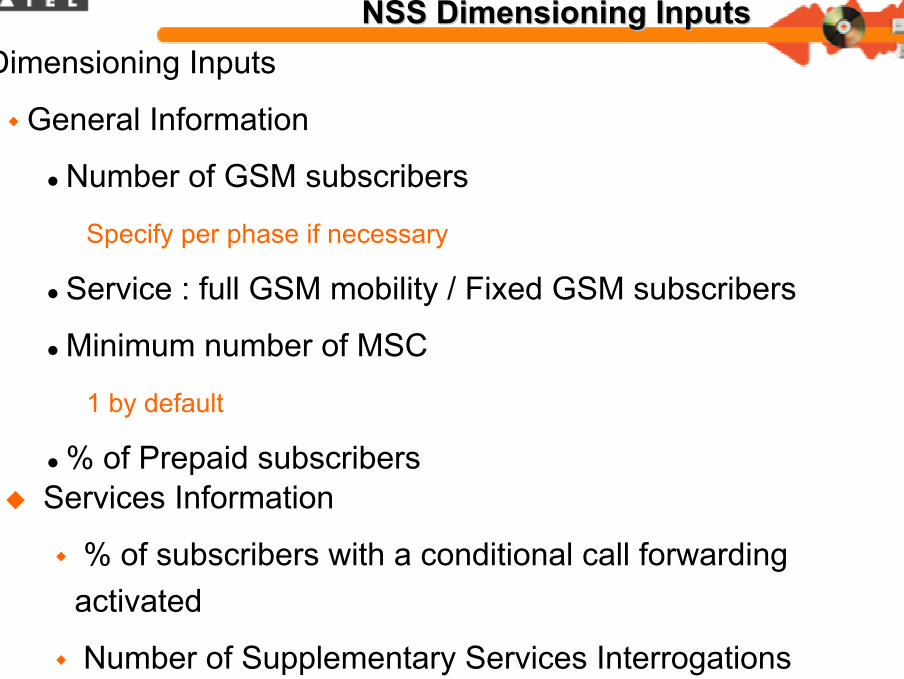
NSS Dimensioning InputsNSS Dimensioning InputsDimensioning Inputs
General Information
Number of GSM subscribers
Specify per phase if necessary
Service : full GSM mobility / Fixed GSM subscribers
Minimum number of MSC
1 by default
% of Prepaid subscribersServices Information
% of subscribers with a conditional call forwarding activated
Number of Supplementary Services Interrogations
Per MS per hour
54
Dimensioning Inputs
Traffic
Average Traffic per Subscriber (OT+TT)
Specify if Prepaid and Postpaid traffic are different or identical
Mean Call duration (in seconds)
Overload coefficient in Traffic (LoadB/LoadA)
% of Originating Call, % of Terminating, % of Mobile-Mobile
NSS Dimensioning InputsNSS Dimensioning Inputs

55
Dimensioning Inputs
Traffic
% Fax / Data calls
by default 1%
Mean Call duration for Fax/Data (in seconds)
Number of originating SMS calls (Nb/MS/h)
Number of terminating SMS calls (Nb/MS/h)
Direct calls towards Voice Mail (% on OC and duration)
Forwarded calls towards Voice Mail (% on Rerouted calls and duration)
% of MS using conference
NSS Dimensioning InputsNSS Dimensioning Inputs

56
Dimensioning Inputs
IN characteristics
% of IN call
Type of IN used (IN-CS1, Camel Phase1, Camel Phase2,...)
Type and characteristics of (Prepaid, VPN,...)
Intelligent Peripheral required (digital announcement, DTMF reception,...)
Only if IN services
NSS Dimensioning InputsNSS Dimensioning Inputs

57
Dimensioning Inputs
Interface Information
SDH/STM1 interface possible on PLMN/PSTN
– Possible if the customer has a SDH Network and ADM connection
available
Signalling (standard ISUP V2, R2 signaling,...)
– By default 100% ISUP V2
Trunk Impedance (75ohms, 120ohms)
Number of Signalling links (towards SMSC, Voice Mail, SCP, others
switches,...)
Number of PCM towards SMSC, Voice Mail, SCP,...
NSS Dimensioning InputsNSS Dimensioning Inputs

58
∇Mobility
Location Registration
Intra VLR Location Updates
Per MS per hour
Inter VLR Location Updates
Per MS per hour
HandoverHO number of intra-MSC handovers Inter VLR Location Updates
Per MS per hourHO number of subsequent inter-MSC handovers
Per MS per hour
NSS Dimensioning InputsNSS Dimensioning Inputs

59
Mobility
RoamingRO Ratio of HLR subscribers visiting other networks (out-roamers) (%)
RO Ratio of MSC subscribers coming from other networks (in-roamers) (%)
NSS Dimensioning InputsNSS Dimensioning Inputs